
Space engineering
Testing
Foreword
This Standard is one of the series of ECSS Standards intended to be applied together for the management, engineering and product assurance in space projects and applications. ECSS is a cooperative effort of the European Space Agency, national space agencies and European industry associations for the purpose of developing and maintaining common standards. Requirements in this Standard are defined in terms of what shall be accomplished, rather than in terms of how to organize and perform the necessary work. This allows existing organizational structures and methods to be applied where they are effective, and for the structures and methods to evolve as necessary without rewriting the standards.
This Standard has been prepared by the ECSS-E-ST-10-03 TA Task Force, reviewed by the ECSS Executive Secretariat and approved by the ECSS Technical Authority.
Disclaimer
ECSS does not provide any warranty whatsoever, whether expressed, implied, or statutory, including, but not limited to, any warranty of merchantability or fitness for a particular purpose or any warranty that the contents of the item are error-free. In no respect shall ECSS incur any liability for any damages, including, but not limited to, direct, indirect, special, or consequential damages arising out of, resulting from, or in any way connected to the use of this Standard, whether or not based upon warranty, business agreement, tort, or otherwise; whether or not injury was sustained by persons or property or otherwise; and whether or not loss was sustained from, or arose out of, the results of, the item, or any services that may be provided by ECSS.
Published by: ESA Requirements and Standards Division
ESTEC, ,
2200 AG Noordwijk
The
Copyright: 2012© by the European Space Agency for the members of ECSS
Change log
|
ECSS-E-10-03A
|
First issue
|
|
ECSS-E-10-03B
|
Never issued
|
|
ECSS-E-ST-10-03C
|
Second issue.
|
Introduction
The requirements on the systems engineering process are gathered in ECSS-E-ST-10; while specific aspects are further elaborated in dedicated standards, in particular: ECSS-E-ST-10-06, ECSS-E-ST-10-02 and the present standard (ECSS-E-ST-10-03)
In the System Engineering branch (ECSS‐E‐10) this standard aims at a consistent application of on ground testing requirements to allow proper qualification and acceptance of space products
Experience has demonstrated that incomplete or improper on ground testing approach significantly increase project risks leading to late discovery of design or workmanship problem(s) or in-orbit failure(s).
Testing is part of the system engineering process as defined in ECSS‐E‐ST‐10. This starts at the early phase of the mission when defining verification process in terms of the model philosophy and test sequence and ends at the last testing phase prior launch.
In the level of decomposition of a space system, this standard addresses the requirements for space segment element and space segment equipment.
The document is organised such that:
clause 4 provides requirements for overall test programme, test management and test conditions, tolerances and accuracy;
clause 5 provides requirements for Space segment equipment;
clause 6 provides requirements for Space segment element;
clause 7 provides requirements for Pre-launch testing.
Clauses 5 and 6 are organised as follows:
general requirements for the products under test applicable to all models (clause 5.1 or 6.1);
requirements applicable to qualification model (clause 5.2 or 6.2);
requirements applicable to acceptance model (clause 5.3 or 6.3);
requirements applicable to protoflight model (clause 5.4 or 6.4);
detailed implementation requirements (clause 5.5 or 6.5);
In the clause providing requirements for each model (i.e. clauses 5.2, 5.3, 5.4, 6.2, 6.3 and 6.4), the first table of the clause:
lists all types of test and defines their applicability and conditions;
links to the second table of the clause that defines tests level and duration;
provides reference to the clause defining the detailed implementation requirements for the given test (clause 5.5 or 6.5).
For space segment equipment, the required sequence of test, for each model, is defined after the two tables in clause 5.2, 5.3 or 5.4.
Since testing activities are part of the overall verification activities, test documentation to be produced (DRD’s) are either specified in the ECSS-E-ST-10-02 (case of the test report) or in this document.
Annex D gives guidelines for performing the tailoring of this standard as well as the generation of the compliance and verification matrices.
Scope
This standard addresses the requirements for performing verification by testing of space segment elements and space segment equipment on ground prior to launch. The document is applicable for tests performed on qualification models, flight models (tested at acceptance level) and protoflight models.
The standard provides:
Requirements for test programme and test management,
Requirements for retesting,
Requirements for redundancy testing,
Requirements for environmental tests,
General requirements for functional and performance tests,
Specific requirements for functional and performance tests are not part of this standard since they are defined in the specific project documentation.
Requirements for qualification, acceptance, and protoflight testing including qualification, acceptance, and proto-fight models’ test margins and duration,
Requirements for test factors, test condition, test tolerances, and test accuracies,
General requirements for development tests pertinent to the start of the qualification test programme,
Development tests are specific and are addressed in various engineering discipline standards.
Content of the necessary documentation for testing activities (e.g. DRD).
Due to the specific aspects of the following types of test, this Standard does not address:
Space system testing (i.e. testing above space segment element), in particular the system validation test,
In-orbit testing,
Testing of space segment subsystems,
Tests of space segment subsystems are often limited to functional tests that, in some case, are run on dedicated models. If relevant, qualification tests for space segment subsystems are assumed to be covered in the relevant discipline standards.
Testing of hardware below space segment equipment levels (including assembly, parts, and components),
Testing of stand-alone software,
For verification of flight or ground software, ECSS-E-ST-40 and ECSS-Q-ST-80 apply.
Qualification testing of two-phase heat transport equipment,
For qualification testing of two-phase heat transport equipment, ECSS-E-ST-31-02 applies.
Tests of launcher segment, subsystem and equipment, and launch facilities,
Tests of facilities and ground support equipment,
Tests of ground segment.
This standard may be tailored for the specific characteristic and constrains of a space project in conformance with ECSS-S-ST-00. Annex D gives guidelines for performing this tailoring.
Normative references
The following normative documents contain provisions which, through reference in this text, constitute provisions of this ECSS Standard. For dated references, subsequent amendments to, or revision of any of these publications do not apply. However, parties to agreements based on this ECSS Standard are encouraged to investigate the possibility of applying the more recent editions of the normative documents indicated below. For undated references, the latest edition of the publication referred to applies.
|
ECSS-S-ST-00-01
|
ECSS system - Glossary of terms
|
|
ECSS-E-ST-10-02
|
Space engineering - Verification
|
|
ECSS-E-ST-20
|
Space engineering - Electrical and electronic
|
|
ECSS-E-20-01
|
Space engineering - Multipaction design and test
|
|
ECSS-E-ST-20-06
|
Space engineering - Spacecraft charging
|
|
ECSS-E-ST-20-07
|
Space engineering - Electromagnetic compatibility
|
|
ECSS-E-ST-20-08
|
Space engineering - Photovoltaic assemblies and components
|
|
ECSS-E-ST-31
|
Space engineering - Thermal control general requirements
|
|
ECSS-E-ST-32
|
Space engineering - Structural general requirements
|
|
ECSS-E-ST-32-02
|
Space engineering - Structural design and verification of pressurized hardware
|
|
ECSS-E-ST-32-10
|
Space engineering - Structural factors of safety for spaceflight hardware
|
|
ECSS-E-ST-32-11
|
Space engineering - Modal survey assessment
|
|
ECSS-E-ST-33-01
|
Space engineering - Mechanisms
|
|
ECSS-M-ST-40
|
Space project management - Configuration and information management
|
|
ECSS-Q-ST-10-09
|
Space product assurance - Nonconformance control system
|
|
ECSS-Q-ST-20-07
|
Space product assurance - Quality assurance for test centres
|
|
ECSS-Q-ST-40
|
Space product assurance - Safety
|
|
ECSS-Q-ST-70-01
|
Space product assurance - Cleanliness and contamination control
|
|
ISO 3740:2000
|
Acoustics - Determination of sound power levels of noise sources - Guidelines for the use of basic standards
|
Terms, definitions and abbreviated terms
Terms from other standards
For the purpose of this standard, since ECSS-S-ST-00-01 has not been published at the time of the publication of this standard, the introduction part of the ECSS Glossary has been copied here.
For the purpose of this standard; the terms and definitions from ECSS-S-ST-00-01 apply, and in particular the following:
flight model
lifetime
protoflight model
qualification model
space segment element
space segment equipment
space segment subsystem
structural model
system
ECSS-S-ST-00-01C defines the highest-level system within a space project - i.e. the one at the mission-level - as the “Space System”. The breakdown of a typical space system and the definition of standard terms for the constituent levels within the breakdown are given below (see Figure 31 and subsequent definitions).
For this standard only, the terms for the Space Segment are defined in 3.1.
Since any definition always includes some ambiguity and in order to allow the user of the testing standard to clearly classify the item under test in the right category (i.e. Space segment Element, or equipment the table below give a list of example (see Figure 32). This table, however, is not exhaustive
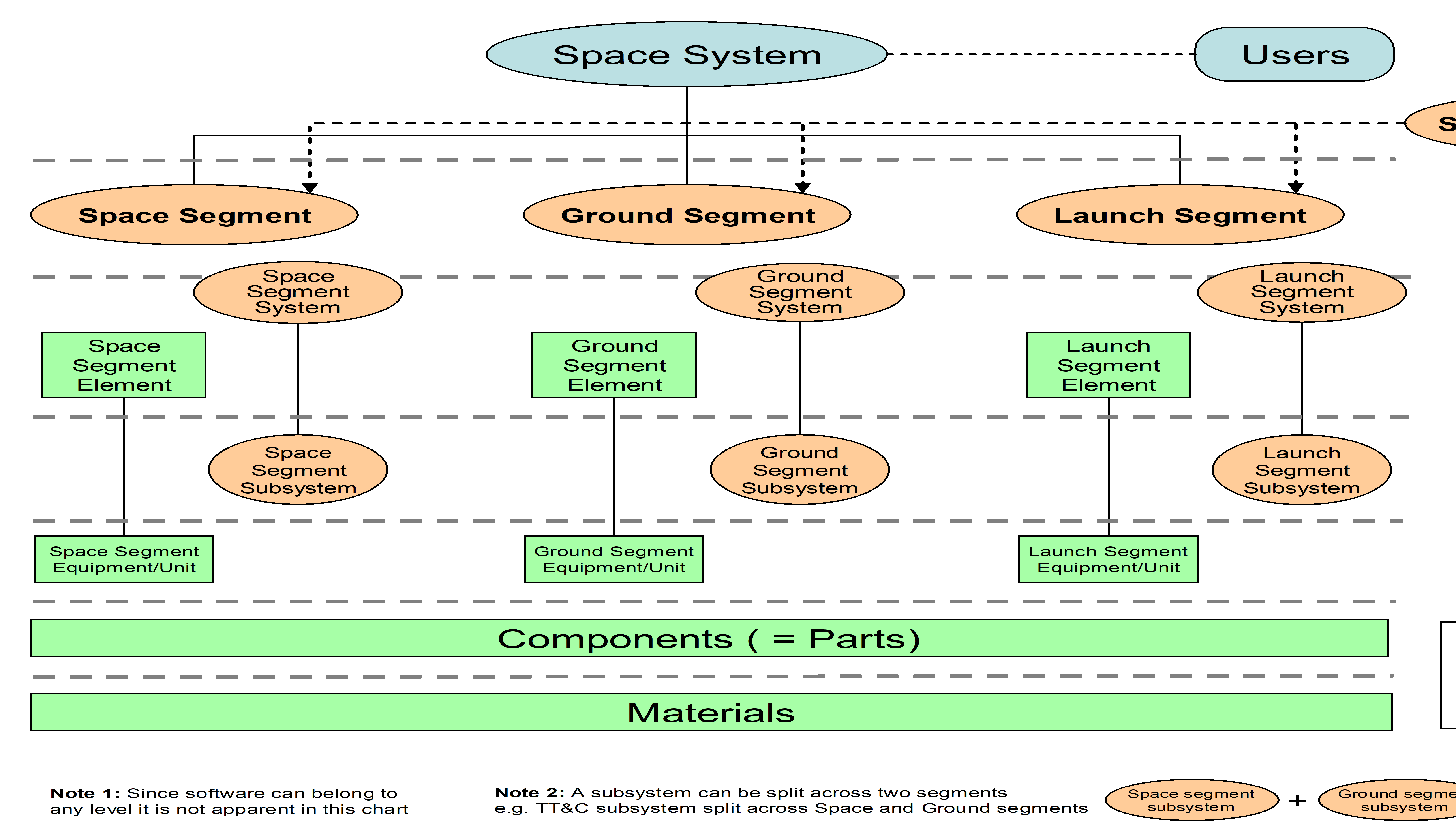 Figure 31: Space system breakdown
The following terms are copied from ECSS-S-ST-00-01C Draft 1.1. Cross-references in these terms are within ECSS-S-ST-00-01C Draft 1.1.
systemset of interrelated or interacting functions constituted to achieve a specified objective
space systemsystem that contains at least a space, a ground or a launch segment
Generally a space system is composed of all three segments and is supported by a support segment.
space segmentpart of a space system, placed in space, to fulfil the space mission objectives
space segment systemsystem within a space segment
Examples are given in Annex B.1.
space segment elementelement within a space segment
- 1 A space segment element can be composed of several embedded space segment elements, e.g. a spacecraft is composed of instruments, a payload module and a service module.
- 2 Examples are given in Annex B.1.
stand-alone space segment elementspace segment element that performs its mission autonomously
For example: satellite, rover, lander.
embedded space segment elementspace segment element that performs its mission as part of another space segment element
For example: platform, module, instrument, payload.
space segment subsystemsubsystem within a space segment
Examples are given in Annex B.1.
space segment equipmentequipment within a space segment
Examples are given in Annex B.1.
componentset of materials, assembled according to defined and controlled processes, which cannot be disassembled without destroying its capability and which performs a simple function that can be evaluated against expected performance requirements
- 1 The term "part" is synonymous.
- 2 The term "part" is preferred when referring to purely mechanical devices.
- 3 The term "component" is preferred for EEE devices.
partsee “component”
materialraw, semi-finished or finished substance (gaseous, liquid, solid) of given characteristics from which processing into a component or part is undertaken
flight model (FM)end product that is intended for flight
- 1 The flight model is subjected to formal functional and environmental acceptance testing.
- 2 More detailed information on the build standard and the use of this model is given in ECSS-E-HB-10-02.
lifetimeperiod, or number of cycles, over which a product is required to perform according to its specification
protoflight model (PFM)flight model on which a partial or complete protoflight qualification test campaign is performed before flight
More detailed information on the build standard and the use of this model is given in ECSS-E-HB-10-02.
qualification model (QM)model, which fully reflects all aspects of the flight model design, used for complete functional and environmental qualification testing
-
1 A qualification model is only necessary for newly-designed hardware or when a delta qualification is performed for adaptation to the project.
-
2 The qualification model is not intended to be used for flight, since it is overtested.
-
3 More detailed information on the build standard and the use of this model is given in ECSS-E-HB-10-02.
structural model (SM)structurally representative model of the flight model used for qualification of the structural design and for correlation with structural mathematical models -
1 The system structural model usually consists of a representative structure, with structural dummies of the flight equipment, and also includes representative mechanical parts of other subsystems (e.g. mechanisms and solar panels).
-
2 The system structural model is also used for final validation of test facilities, GSE, and associated procedures.
-
3 More detailed information on the build standard and the use of this model is given in ECSS-E-HB-10-02.
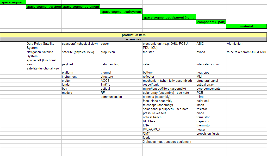
A deployable solar array is an equipment composed of one or several solar panels (panel substrate and photovoltaic assembly), deployment mechanism including hinges, restrain and release mechanism, and yoke.
Figure 32: Space segment examples
For the purpose of this standard, the following terms and definitions from ECSS-E-ST-10-02 apply:
commissioning
model philosophy
test
For the purpose of this Standard, the following terms and definitions from ECSS-E-ST-31 apply:
acceptance temperature range
minimum switch ON temperature
predicted temperature range
qualification temperature range
temperature reference point
For the purpose of this Standard, the following terms and definitions from ECSS-E-ST-32 apply:
burst pressure
design burst pressure
factor of safety
limit load (LL)
maximum design pressure (MDP)
proof factor
proof pressure
proof test
Terms specific to the present standard
24-hour equivalent noise exposure level
equivalent sound pressure level (Leq) to which the crew members are exposed over a 24-hour period; expressed in dBA
0 dBA corresponds to 20 µPa.
a-weighting
adjustments typically made to acoustic measurements to approximate the response of the human ear
abbreviated functional test (AFT)
See "reduced functional test (RFT)"
acceptance level
test level reflecting the maximum level expected to be encountered during the flight product lifetime increased by acceptance margins
acceptance margin
increase of the environmental, mechanical, thermal, electrical, EMC, or operational extremes above the worst case levels predicted over the specified product lifetime for the purpose of workmanship verification
- 1 Margins can include an increase in level or range, an increase in duration or cycles of exposure, as well as any other appropriate increase in severity.
- 2 For thermal acceptance margin refer also to ECSS-E-ST-31.
accuracy of measurement
degree of closeness between a measured quantity value and its true value
The accuracy depends from the measurement process (e.g. instrument or machine, operator, procedure; environmental conditions).
crewed space segment element
space segment design to ensure the safe presence of crew onboard
development test prior qualification
test to support the design feasibility and to assist in the evolution of the design
dwell time
duration necessary to ensure that internal parts or subassembly of a space segment equipment have achieved thermal equilibrium, from the start of temperature stabilisation phase, i.e. when the temperature reaches the targeted test temperature plus or minus the test tolerance
environmental tests
tests applied to a product simulating (together or separately) environmental conditions as encountered during its operational life cycle
Environmental tests cover natural and induced environments.
full functional test (FFT)
comprehensive test that demonstrates the integrity of all functions of the item under test, in all operational modes, including back-up modes and all foreseen transitions
-
1 The main objectives of this test is to demonstrate absence of design manufacturing and integration error.
-
2 FFT exists at the different level of decomposition of a space segment element. For satellite they also called system functional test (SFT) or integrated system test (IST).
maximum expected acceleration
acceleration value determined from the combined effects of the steady state acceleration and the transient response of the item as it will experience during its life time -
1 This term is equivalent to limit load (as defined in E-ST-32).
-
2 Examples of events during life time are transportation, handling, engine ignition, engine burnout, and stage separation.
maximum expected acoustic spectrum
maximum value of the time average root-mean-square (r.m.s.) sound pressure level (SPL) in each frequency band occurring inside the payload fairing, orbiter, or cargo bay, which occurs during flight events -
1 E.g. lift-off, powered flight or re-entry.
-
2 The maximum expected acoustic environment test spectrum is specified in octave or 1/3 octave bands over a frequency range of 31,5 Hz to 10 kHz. The duration of the maximum environment is the total period when the overall amplitude is within 6 dB of the maximum overall amplitude.
maximum expected shock
worst cases of the collection of the shock at their mounting interface due to every possible cause -
1 For example: causes of shocks are stage, shroud or satellite separation pyro elements, non-explosive actuators, mechanisms with energy release, appendage latching, and fuel valves.
-
2 Shocks can be characterized by their time histories, shock response spectrum, or impulse geometry.
-
3 Refer to ECSS-E-HB-32-25 for additional information.
maximum expected random vibration spectrum
maximum expected environment imposed on the space segment element and space segment equipment due to broad band random forcing functions within the launch element or space segment element during flight or from ground transportation and handling -
1 E.g. lift-off acoustic field, aerodynamic excitations, and transmitted structure-borne vibration.
-
2 A different spectrum can exist for different space segment equipment zones or for different axis. The space segment equipment vibration levels are based on vibration response measurements or model prediction made at the space segment equipment attachment points during ground acoustic tests or during flight. The duration of the maximum environment is the total period during flight when the overall level is within 6 dB of the maximum overall level.
-
3 The power spectral density is based on a frequency resolution of 1/6 octave (or narrower) bandwidth analysis, over a frequency range of 20 Hz to 2000 Hz.
maximum expected sinusoidal vibration environment
maximum expected environment imposed on the space segment element and space segment equipment due to sinusoidal and narrow band random forcing functions within the launch element or space segment element during flight or from ground transportation and handling
In flight, sinusoidal excitations are caused by unstable combustion, by coupling of structural resonant frequencies (POGO), or by imbalances in rotating space segment equipment in the launch element or space segment element. Sinusoidal excitations occur also during ground transportation and handling due to resonant responses of tires and suspension systems of the transporters.
multipaction
resonant back and forth flow of secondary electrons in a vacuum between two surfaces separated by a distance such that the electron transit time is an odd integral multiple of one half the period of the alternating voltage impressed on the surface
The effects of multipaction can be loss of output power up to reaching the multipaction breakdown voltage leading to the generation of spark.
notching
reduction of the input level or spectrum to limit structural responses at resonant frequencies according to qualification or acceptance loads during a vibration test
Notching is a general accepted practice in vibration testing to avoid over testing of the item under test. Implementation of notching is subject to customer approval and when relevant to Launcher authority approval
operational modes
combination of operational configurations or conditions that can occur during the product lifetime for space segment equipment or space segment element
For example: Power-on or power-off, command modes, readout modes, attitude control modes, antenna stowed or deployed, and spinning or de-spun.
performance test
test to verify that the item under test performs according to its specifications while respecting its operational requirements
Performance tests are mission specific therefore their details are not specified under this standard.
polarity test
test to verify the correct polarity of the functional chains (mainly AOCS) or equipment of the space segment element from sensors to actuators, through a number of interfaces and processing.
-
1 A polarity error can be generated throughout the development process: interface documentation, design, H/W manufacturing, S/W development, satellite AIT, satellite database.
-
2 A polarity error can be generated by any element of the functional chain: sensor or actuator design, sensor or actuator mounting, harness, interface units, software algorithms.
-
3 Polarity inversion on Safe Mode control loops can cause a satellite loss.
-
4 This term "sign test" is synonymous.
qualification level
test level reflecting the maximum level expected to be encountered during the flight product lifetime increased by qualification margins -
For thermal the qualification margin applies on top of the acceptance margin.
qualification margin
increase of the environmental, mechanical, electrical, EMC, or operational extremes above the worst case levels predicted over the specified product lifetime for the purpose of design margin demonstration -
1 Margins can include an increase in level or range, an increase in duration or cycles of exposure, as well as any other appropriate increase in severity.
-
2 This definition is not applicable for thermal aspects. Refer to ECSS-E-ST-31 for "qualification margin".
reduced functional test (RFT)
sub-set of the full functional test to verify the integrity of the major functions of the item under test, with a sufficiently high degree of confidence, in a relatively short time
* The term "abbreviated functional test (AFT)" is synonymous.
residual life
time left before a product is no longer able to achieve minimum acceptable performance requirements, including availability
Criteria can be estimated in terms of serviceability or structural strength for example.
resolution
minimum readable value of a quantity on a measurement system
The resolution is accounted for in the accuracy.
resonance search
frequency sweep of low level sinusoidal vibrations to characterise main resonant modes for preparing the higher level runs, and to show possible deficiencies in workmanship, as a consequence of high level runs
Resonance search is also known as “signature test”, “low level sinusoidal vibration test”, “low level sine sweep”, “low level sweep” or “low level test”.
reverberation time (T60)
duration necessary for the sound level to decrease by 60 dB after the switch off of the sound source
shock response spectrum (SRS)
graphical representation of a transient waveform determined by the response of a set of single degree of freedom oscillators using a defined amplification factor Q
- 1 The Shock Response Spectrum can be defined for any input or response parameters of interest (displacement, velocity, or acceleration). For aerospace structures it is common to define the input transient in terms of acceleration.
- 2 The acceleration amplification factor Q is conventionally chosen equal to 10, corresponding to a factor of critical damping equal to 5 %. In situations when damping is known, Q can be chosen accordingly.
- 3 The Shock Response Spectrum allows characterizing the shock effect in order to estimate its severity or its damaging potential.
- 4 There are several representations of Shock Response Spectrum, including positive, negative, primary, residual and maximax. The latter SRS envelopes the previous four and is the most commonly used for shock testing.
sign test
see “polarity test”
temperature cycle
transition from an initial temperature to the same temperature, with excursion within a specified range
test block
aggregation of several tests grouped by discipline
tolerance
limiting or permitted range of values of a specified test level without affecting the test objectives
The tolerance is typically specified as deviation from a specified value, or as an explicit range of allowed values. Tolerance can be symmetrical, as in 40 ±0,1, or asymmetrical, such as 40 -0,2/+0,1.
Abbreviated terms
For the purposes of this Standard the following abbreviated terms apply.
|
Abbreviation
|
Meaning
|
|
AFT
|
abbreviated functional test
|
|
AIT
|
assembly, integration and test
|
|
AITP
|
assembly, integration and test plan
|
|
AIV
|
assembly, integration and verification
|
|
AVT
|
acceptance vibration test
|
|
CCB
|
configuration control board
|
|
CoG
|
centre of gravity
|
|
DRD
|
document requirements definition
|
|
EC
|
European Commission
|
|
EGSE
|
electrical ground support equipment
|
|
EM
|
engineering model
|
|
EMC
|
electromagnetic compatibility
|
|
EMCCP
|
electromagnetic compatibility control plan
|
|
EQM
|
engineering qualification model
|
|
ESD
|
electrostatic discharge
|
|
FFT
|
full functional test
|
|
FM
|
flight model
|
|
FOP
|
flight operation plan
|
|
GSE
|
ground support equipment
|
|
HFE
|
human factors engineering
|
|
HMI
|
human-machine interface
|
|
ICD
|
interface control document
|
|
KIP
|
key inspection point
|
|
LCDA
|
launcher coupled dynamic analysis
|
|
LEOP
|
launch and early orbit phase
|
|
MDP
|
maximum design pressure
|
|
MIP
|
mandatory inspection point
|
|
MoI
|
moment of inertia
|
|
NC
|
noise criterion
|
|
NCR
|
nonconformance report
|
|
NRB
|
nonconformance review board
|
|
OSPL
|
overall sound pressure level
|
|
PFM
|
protoflight model
|
|
PIM
|
passive intermodulation
|
|
PSD
|
power spectral density
|
|
PT
|
performance test
|
|
PTR
|
post test review
|
|
QM
|
qualification model
|
|
r.m.s.
|
root-mean-square
|
|
RF
|
radio frequency
|
|
RFT
|
reduced functional test
|
|
SEP
|
system engineering plan
|
|
SFT
|
system functional test
|
|
SPL
|
sound pressure level
|
|
SRS
|
shock response spectrum
|
|
SVT
|
system validation test
|
|
TB
|
thermal balance
|
|
TC
|
telecommand
|
|
TCS
|
thermal control system
|
|
TM
|
telemetry
|
|
TPRO
|
test procedure
|
|
TR
|
test review
|
|
TRB
|
test review board
|
|
TRP
|
temperature reference point
|
|
TRPT
|
test report
|
|
TRR
|
test readiness review
|
|
TV
|
thermal vacuum
|
|
TQ
|
qualification temperature
|
|
TA
|
acceptance temperature
|
|
TD
|
design temperature
|
|
TOp
|
operating temperature
|
|
TNOp
|
non-operating temperature
|
|
TSPE
|
test specification
|
|
TT&C
|
telemetry, tracking and command
|
|
TWT
|
travelling wave tube
|
|
VCD
|
verification control document
|
|
VP
|
verification plan
|
General requirements
Test programme
A coherent test programme shall be established, encompassing each verification stage and level to implement the verification by testing.
- 1 The testing programme is performed incrementally at different product decomposition levels.
- 2 Refer to clause 3.1 for determining the type of item for which the test programme is defined (i.e. space segment equipment or space segment element), in particular the example table.
- 3 The number and type of testing levels depends upon the complexity of the project and on its characteristics in accordance with the Verification programme (see ECSS-E-ST-10-02).
- 4 The test programme documentation is defined in 4.3.3.
The customer and the supplier shall agree the need to treat a space segment element as a space segment equipment.
This is typically the case for small instrument.
AITP and test specifications shall be derived from the product requirements, verification plan and verification control document (VCD).
Verification plan and VCD are defined in ECSS-E-ST-10-02.
Test procedures shall be derived from test specifications and AITP.
Test programme and its implementation shall be in conformance with safety requirements of ECSS-Q-ST-40 and ECSS-Q-ST-20-07.
Development test prior qualification
Development test of a product shall be completed prior to the start of its formal qualification testing.
- Development tests are conducted over a range of operating conditions that can exceed the design range.
Development tests shall not be conducted on qualification or flight models or parts of it.
Records of test configuration, test results and other pertinent data shall be maintained.
This kind of information can be used for investigation when failure occurs during the qualification and acceptance, or for other investigations.
Test management
General
The supplier shall assign clear responsibility for the implementation of the test programme.
The customer, or its duly appointed representative, shall have the right to participate to all test phases.
Test reviews
Test programme
The test programme shall be decomposed in blocks.
The general test programme is reviewed at the CDR as per ECSS-M-ST-10.
The definition of the blocks of requirement 4.3.2.1a shall be agreed between the customer and supplier.
- 1 Test block definition depends mainly on the item under test, the facility and the contractual agreement. A test block can include one or more tests. For equipment, usually one test block covers the full test programme.
- 2 Typical test blocks for space segment elements are:
- Integration
- Alignment
- Leak/proof pressure
- Mechanical (Static load test, sinusoidal, acoustic, random, modal survey, shock)
- EMC conducted
- EMC radiated/auto-compatibility/RF
- Thermal (TB/TV test)
- Functional and performance test
- Final preparation
Each test block shall include the following formal reviews: - test readiness review (TRR);
- post test review(s) (PTR);
- test review board (TRB).
- 1 TRRs from several blocks can be combined, TRRs can also be combined with a PTR of the previous block.
- 2 Depending on the nature of the test, the customer can decide to establish additional key-points between formal reviews. Typical examples are transition between level and axes in vibration tests and transition between test phases in TV/TB tests.
Test readiness review (TRR)
A TRR shall be held before the start of the test activity to verify that all conditions allow to proceed with the test.
The TRR shall address the following topics:
- test documentation availability and suitability, including:
- approved AITP,
- approved test specification,
- test predictions (when relevant),
- approved test procedures (including contingency and emergency procedures),
- approved measurement point plan,
- approved test facility readiness report,
- approved test schedule, and
- acceptance data package of lower level items.
- item under test configuration;
- test configuration/set-up;
- inspection status report of KIP, MIP, or both;
- test facility, environmental conditions, test instrumentations, calibration, maintenance status;
- cleanliness condition, hazard and safety;
- ground support equipment (GSE) and infrastructures;
- status of nonconformances that affect the item under test, its associated GSE, or the test facility;
- waivers status, and deviations;
- personnel qualification and availability;
- results from test rehearsal using the test facility with or without the item under test, when relevant;
- test pass/fail criteria completeness;
- assignment of responsibilities;
- test schedule.
- 1 For 4.3.2.2b.1(f), the content of the facility readiness report is defined in ECSS-Q-ST-20-07.
- 2 The level of details according to which each topic is addressed, is different for the general test programme TRR than for each block test TRR.
The following parties shall participate to the TRR: - the chairperson, who is the product assurance manager of the authority responsible for the test;
- product assurance from all involved parties;
- project engineer from all involved parties;
- AIT from all involved parties;
- specialists, when necessary from all involved parties;
- facility representative;
- other as relevant.
For example launcher authority for tests related to launcher interface or other company representative that will take over the responsibility of the hardware after delivery.
All the open points shall be clearly identified and actions assigned with closure date before the execution of the test.
The output of the TRR shall be a decision to proceed with the test or not.
Post test review (PTR)
A PTR shall be held in order to formally declare the test completed and allow the release of the item under test and test facility for further activity.
The release of the test facility includes the breaking of the test configuration.
The PTR shall address the following topics:
- verification that all test data were acquired, recorded, and archived in conformance with the test specification and test procedure requirements;
- verification that the process for test anomalies and NCRs, raised during the test, was initiated, and all needed inspection, test data and test configuration were acquired;
- confirmation that tests were performed according to the AITP, the test specification and the test procedures, with the exceptions of what is covered by agreed procedure variations or NCRs;
- status of compliance of the item under test to the relevant requirement;
- post test status of GSE;
- post item under test configuration based on inspection and cleanliness report;
- identification of the open points with assignment of actions for their closure, as well as lessons learned drawn. The following parties shall participate to the PTR:
- product assurance;
- project engineer;
- AIT;
- facility representative;
- other, including specialist, as relevant.
For example launcher authority for tests related to launcher interface or other company representative that will take over the responsibility of the hardware after delivery.
Test review board (TRB)
A TRB shall be held to review all results and conclude on the test completeness and achievement of objectives.
The TRB shall address the following topics:
- test documentation availability, including:
- test report as per ECSS-E-ST-10-02 Annex C,
- facility report when relevant,
- inspection report including cleanliness report,
- list of NCRs,
- copy of NCRs raised during test with the related NRB minutes of meeting, and associated request(s) for waiver, and
- list of procedure deviations.
- compliance with the test specification, and variations to the AITP;
- status of compliance of the item under test to the relevant requirement;
- post test status of GSE;
- post item under test configuration based on inspection and cleanliness report;
- review of all still open NCRs raised during test in order to assess that there is no impact on the test objectives achievement;
- lessons learned to be drawn. The following parties shall participate to the TRB:
- product assurance;
- project engineer;
- AIT;
- facility representative;
- other, including specialist, as relevant.
For example launcher authority for tests related to launcher interface or other company representative that will take over the responsibility of the hardware after delivery.
Test documentation
General
Clauses 4.3.3.2 to 4.3.3.5 define the Test programme documentation (AITP, Test specification, Test procedure, and Test report) generated at all product levels.
These documents are derived from the System Engineering Plan (SEP) and from the Verification Plan (VP).
Assembly, integration and test plan (AITP)
The supplier shall establish the AITP in conformance with the DRD in Annex A.
At space segment equipment level, the AITP can be called test plan.
The agreed AITP shall be available, at the latest, for the TRR of the test programme.
The way the requirement 4.3.3.2b is achieved shall be agreed between the customer and the supplier.
Test specification (TSPE)
The supplier shall establish the test specification in conformance with the DRD in Annex B.
The agreed test specification shall be available at the relevant test block TRR and on time to allow procedure preparation.
The way the requirement 4.3.3.3b is achieved shall be agreed between the customer and the supplier.
Test procedure (TPRO)
The supplier shall establish the test procedure in conformance with the DRD in Annex C.
The test procedure, derived from the agreed test specification, shall be available at the relevant test block TRR.
The way the requirement 4.3.3.4b is achieved shall be agreed between the customer and the supplier.
Test report (TRPT)
The supplier shall establish the test report in conformance with the DRD in Annex C of ECSS-E-ST-10-02.
The test report describes test execution, results and conclusions in the light of the test requirements. It contains the test description and the test results including the as-run test procedures, the considerations and conclusions with particular emphasis on the close-out of the relevant verification requirements including any deviation.
The test report shall be available prior to the TRB.
Anomaly or failure during testing
Any failure or anomaly during testing shall be recorded.
All nonconformances shall be managed in conformance with ECSS-Q-ST-10-09.
The NRB shall decide on the necessity and extent of any retest activity in order to demonstrate the correctness of the disposition made.
Test data
Test measurements and the environmental conditions shall be recorded for subsequent evaluation.
A database of parameters shall be established for trend analysis.
Trend analysis shall be performed using test data acquired across test sequences.
Test conditions, tolerances, and accuracies
Test conditions
Test conditions shall be established using predicted environment plus margins.
This can be done using previous mission flight data, relevant ground environments, analytical prediction, relevant previous test results, or a combination thereof.
Tests shall be performed simulating the mission envelope, including operational and non-operational conditions with margins.
For items tested in an environment different from the one it is expected to operate, the possible differences in behaviour shall be accounted for in the test levels and duration.
In this case, the test levels and duration are modified based on analyses. For example to prevent effects of convective heat transfer that reduce thermal gradients.
Cleanliness and contamination control for test programmes shall conform to ECSS-Q-ST-70-01.
The quality and safety management system used to operate and maintain test facility(ies) shall be recognized by the customer.
As example, in accordance to quality and safety management system requirements from ECSS-Q-ST-20-07.
Test facilities, tools and instrumentation shall not prevent to fulfil the tests objectives.
The EGSE or other support systems of the item under test shall:
- not jeopardize the results of tests;
- be immune to signals used for susceptibility tests;
- be designed to comply with the applicable legislation, including safety (e.g. EC Directives). The combination of test set-up, test levels durations, and operational modes shall not create conditions that can:
- induce failures of the item under test,
- lead to rejection of adequate item under test, or
- create hazardous conditions.
Test tolerances
Test tolerances bands shall be specified in test error budgets and agreed by the customer prior to start of test.
For the purpose of 4.4.2a test tolerances shall be justified by reference to the uncertainty budget and confidence level of the measurement instrument(s) used.
- 1 EA-4/16 and EA-4/02 (section 2) guidelines can be used to build up the uncertainty budget.
- 2 The tolerances specified in Table 41 are the allowable ranges within which the test parameters can vary, they include instrumentation accuracy.
Quantitative requirements demonstrated by measured test values shall account for test inaccuracies and tolerances, and be compared with the specified requested values.
The tolerances specified in Table 41 shall be applied to the test values.
Changes to the tolerances specified in Table 41 shall be approved by the customer.
For example, when tolerances of Table 41 are detected to be inconsistent with test accuracy values of Table 42.
Table 41: Allowable tolerances
|
Test parameters
|
Tolerances
|
|
1. Temperature
|
Low High
|
|
above 80K
|
Tmin +0/-4 K Tmax -0/+4 K
|
|
|
|
|
T< 80 K
|
Tolerance to be defined case by case
|
|
2. Relative humidity
|
± 10 %
|
|
3. Pressure (in vacuum chamber)
|
|
|
> 1,3 hPa
|
± 15 %
|
|
1,3 10-3 hPa to 1,3hPa
|
± 30 %
|
|
< 1,3 10-3 hPa
|
± 80 %
|
|
4. Acceleration (steady state) and static load
|
-0 / +10 %
|
|
5. Sinusoidal vibration
|
|
|
Frequency (5 Hz to 2000 Hz)
|
± 2 % (or ±1 Hz whichever is greater)
|
|
Amplitude
|
± 10 %
|
|
Sweep rate (Oct/min)
|
± 5 %
|
|
6. Random vibration
|
|
|
Amplitude (PSD, frequency resolution better than 10Hz)
|
|
|
20 Hz - 1000 Hz
|
-1 dB / +3 dB
|
|
1000 Hz - 2000 Hz
|
± 3 dB
|
|
Random overall g r.m.s.
|
± 10 %
|
|
7. Acoustic noise
|
|
|
Sound pressure level, Octave band centre (Hz)
|
|
|
31,5
|
-2 dB /+4 dB
|
|
63
|
-1 dB /+3 dB
|
|
125
|
-1 dB /+3 dB
|
|
250
|
-1 dB /+3 dB
|
|
500
|
-1 dB /+3 dB
|
|
1000
|
-1 dB /+3 dB
|
|
2000
|
-1 dB /+3 dB
|
|
Overall
|
-1 dB /+3 dB
|
|
Sound pressure level homogeneity per octave band
|
+/- 2 dB
|
|
8. Microvibration
|
|
|
Acceleration
|
±10 %
|
|
Forces or torque
|
±10 %
|
|
9. Audible noise (for Crewed Element only)
|
|
|
Sound-power (1/3 octave band centre frequency)
|
|
|
32,5 Hz - 160 Hz
|
±3 dB
|
|
160 Hz – 16 kHz
|
±2 dB
|
|
9. Shock
|
|
|
Response spectrum amplitude (1/12 octave centre frequency or higher)
|
|
|
Shock level
|
- 3 dB/ + 6 dB
|
|
10. Solar flux
|
|
|
in reference plane
|
± 4 % of the set value
|
|
in reference volume
|
± 6 % of the set value
|
|
11. Infrared flux
|
|
|
Mean value
|
± 3 % on reference plane(s)
|
|
12. Test duration
|
-0/+10 %
|
Test accuracies
Test accuracies shall be specified in test error budgets and agreed by the customer prior to test performance.
EA-4/16 and EA-4/02 (section 2) guidelines can be used to build up the overall test measurement accuracy.
The accuracy of test instrumentation shall be verified in accordance with approved calibration procedures, with traceability to international measurement standards.
All test instrumentation shall be within the normal calibration period at the time of the test.
Any anomaly of test instrumentation, detected at the first calibration sequence after the test, shall be reported.
The accuracy of measurement shall be as follows:
- as per Table 42 for the parameters listed, or
- at least one third of the tolerance of the variable to be measured.
The values of Table 42 are typical from test centre capabilities.
Table 42: Test accuracies
|
Test parameters
|
Accuracy
|
|
1. Mass
|
|
|
Space segment equipment and space segment element
|
± 0,05 % or 1 g whatever is the heavier
|
|
2. Centre of gravity (CoG)
|
|
|
Space segment equipment
|
Within a 1 mm radius sphere
|
|
Space segment element
|
± 2,5 mm along launch axis± 1 mm along the other 2 axes
|
|
3. Moment of inertia (MoI)
|
|
|
Space segment equipment and Space segment element
|
± 3 % for each axis
|
|
4. Leak rate
|
One magnitude lower than the system specification, in Pa m3 s-1 at standard conditions (1013,25 Pa and 288,15 K).
|
|
5. Audible noise (for Crewed Element only)
|
|
|
32,5 Hz to 160 Hz
|
± 3 dB
|
|
160 Hz to 16 kHz
|
± 2 dB
|
|
6. Temperature
|
|
|
above 80 K
|
± 2 K
|
|
T< 80 K
|
Accuracy to be defined case by case
|
|
7. Pressure (in vacuum chamber)
|
|
|
> 1,3 hPa
|
± 15 %
|
|
1,3 10-3 hPa to 1,3 hPa
|
± 30 %
|
|
< 1,3 10-3 hPa
|
± 80 %
|
|
8. Acceleration (steady state) and static load
|
± 10 %
|
|
9. Frequency for mechanical tests
|
± 2 % (or ±1 Hz whichever is greater)
|
|
10. Acoustic noise
|
± 0,1dB
|
|
11. Strain
|
± 10 %
|
|
12. EMC
|
See ECSS-E-ST-20-07 clause 5.2.1.
|
|
13. ESD
|
See ECSS-E-ST-20-06
|
Test objectives
General requirements
The test programme shall be defined taking into account the agreed model philosophy.
The model philosophy, including model definition, is detailed in ECSS-E-HB-10-02.
When preparing the overall test programme of a space segment element tests linked to compatibility with ground and launch segment shall also be included.
This covers in particular the system validation test.
Qualification testing
Qualification testing shall be performed to provide evidence that the space segment element or equipment performs in accordance with its specifications in the intended environments with the specified qualification margins.
- 1 The Qualification test programme requirements are defined in ECSS-E-ST-10-02 requirement 5.2.4.2b. and 5.2.4.2c.
- 2 This evidence is used, further to analysis as relevant, to provide via verification reports (defined in ECSS-E-ST-10-02 Annex F) the elements for the close-out of the VCD (defined in ECSS-E-ST-10-02 Annex B).
Qualification testing shall be conducted on dedicated qualification models except when using protoflight approach.
Qualification testing shall be completed and design improvements or modification incorporated and qualified prior to the authorization for the flight product manufacturing.
Upon achievement of qualification the design files shall not be modified.
In case destructive tests are needed (e.g. Burst test), a representative model different from the QM shall be used or the test shall be performed at the end of the qualification programme.
This model can be simplified but needs to fully represent the function tested.
The qualification test levels and durations shall be as specified in Table 52 for space segment equipment and in Table 62 for space segment element.
The test durations identified in Table 52 and Table 62 are the minimum values.
Acceptance testing
Acceptance testing shall be performed to provide evidence that the space segment element or equipment performs in accordance with the specifications in the intended environments with the specified acceptance margins.
This evidence is used, further to analysis as relevant, to provide via verification reports (defined in ECSS-E-ST-10-02 Annex F) the elements for the close-out of the VCD (defined in ECSS-E-ST-10-02 Annex B).
Acceptance testing shall be performed on each flight product, except the one used as Protoflight, to assure freedom from workmanship defects and flawed materials in conformance with ECSS-E-ST-10-02.
The acceptance programme shall be performed, after a qualification programme has been completed (as per clause 4.5.2 or clause 4.5.4).
The FM is built from the same design file than the QM or the PFM used for qualification, as specified in the ECSS-E-ST-10-02 clause 5.2.4.3.
The acceptance test levels and durations shall be as specified in Table 54 for space segment equipment, and in Table 64 for space segment element levels.
The test durations identified in Table 54 and Table 64 are the minimum values.
Protoflight testing
Overview
Protoflight testing is the combination of the qualification and acceptance testing objectives on the first flight model.
The protoflight approach can be applied at each level of decomposition of space system.
To minimize risk, a space segment elements protoflight approach can include test(s) on dedicated model(s), which can later be refurbished in PFM. An example of this is the development of a Structural Model for early mechanical qualification.
Requirements
Protoflight testing shall be performed on the first flight model to provide evidence that the space segment element or equipment performs in accordance with the specifications in the intended environments with the specified qualification margins and to confirm its readiness for delivery and subsequent usage, being free from workmanship defects and flawed materials.
This evidence is used, in addition to analysis as relevant, to provide via verification reports (defined in ECSS-E-ST-10-02 Annex F) the elements for the close-out of the VCD (defined in ECSS-E-ST-10-02 Annex B).
In case destructive tests are needed (e.g. Burst test), a representative model different from the PFM shall be used.
This model can be simplified but needs to fully represent the function tested.
The protoflight test levels and durations shall be as specified in Table 56 for space segment equipment and in Table 66 for space segment element levels.
- 1 The general approach is to select:
- test levels: as qualification levels;
- test durations: as acceptance durations.
- 2 The test durations identified in Table 56 and Table 66 are the minimum values.
Retesting
Overview
ECSS-E-ST-10-02 identifies several situations, in which re-verification is required. However, as the scope and the nature of retesting differ so much, test requirements are defined on a case-by-case basis. Examples of cases involving retesting are described in clauses 4.6.2 to 4.6.5 below.
Implementation of a design modification after completion of qualification
The configuration control board (CCB), as per ECSS-M-ST-40, shall convene to evaluate and decide the extent of the qualification test sequence to be repeated.
Storage after protoflight or acceptance testing
The supplier shall identify the testing requirements during storage and post-storage.
These requirements can be presented in the user manual.
Periodic tests shall be assessed and performed with a frequency accounting for:
- space segment equipment degradation, and
- specific personnel know-how maintenance. Storage configuration shall be agreed with the customer in particular for the deployable mechanisms.
If deployable mechanisms are stored assembled with the space segment elements, the flight tension can be reduced.
The periodic tests during storage shall cover:
- overall functional test,
- testing of the rotating parts,
- power consumption measurement,
- TT&C space segment subsystem through tests caps (space segment element switched ON),
- testing of the propulsion space segment subsystem pressure through the telemetry,
- visual inspection of the separately stored space segment equipment in a suitable clean work area,
- contamination tests on the contamination probes.
Example of age sensitive space segment equipment: Travelling wave tubes (TWTs), batteries and special lubricated mechanisms valves and motors.
Any additional test to the one listed in 4.6.3d shall be identified for customer approval.
The storage procedure shall be submitted to the customer for approval.
Solar array(s) should be stored in a gaseous Nitrogen environment.
This recommendation is also relevant for the solar panels integrated with the photovoltaic assembly, during any transportation phase, and during any long term storage phase after a successful solar panel DRB (Delivery Review Board).
Space segment element or equipment to be re-flown
Space segment element or equipment to be re-flown shall be re-tested before the new flight in accordance with the verification programme and acceptance criteria defined for the new mission.
High level (system or element) functional testing shall be performed in preference to individual low level tests.
Post-landing testing is performed on space products to be recovered at the end of mission and on products which are re-flown.
Flight use of qualification Space segment element or equipment
Use of qualification space segment element or equipment shall not be allowed unless agreed by the customer.
Additional testing of qualification space segment element or equipment subsequently selected for flight shall be compatible with the residual life.
This is done when the customer considers the risk acceptable.
In case of refurbishment or disassembly the qualification space segment element or equipment shall be subjected to an acceptance re-testing to be agreed with the customer.
The extend of the acceptance testing depends on the item past history and on the extend of the modification.
Space segment equipment test requirements
General requirements
The test baseline and sequencing shall be tailored to the specific space segment equipment type for each project.
The types of space segment equipment are uniformly listed at the end of Table 51, Table 53, and Table 55.
Where space segment equipment falls into two or more types, the combination of all required tests specified for each type shall be applied.
For example: A star sensor can be considered to fit both “electronic space segment equipment” and “optical space segment equipment” types, therefore, an EMC test is conducted since it is applicable for electronic space segment equipment, even though there is no requirement for optical space segment equipment.
The test sequence shall be performed, taking into account tests’ applicability, as defined for qualification in Table 51, for acceptance in Table 53, for protoflight in Table 55.
This sequence reflects the principle “Test as you fly”. It is based on a combination of:
- the order in which the environments are encountered during flight, and
- the capability to identify defects as early as possible in the test sequence.
Any unusual or unexpected behaviour shall be evaluated to determine the existence of any trend potentially leading to anomaly or failure situation.
PT and FFT shall be performed at the beginning and at the end of the test programme under ambient conditions.
Those tests provide the criteria for judging the integrity of the space segment equipment thought the overall test programme. The results of both tests should be identical within the test tolerances.
RFT shall be performed before and after each environmental test block as well as before and after transportation.
This test allows verifying the integrity of the space segment equipment.
PT, FFT or RFT, as relevant, shall be performed:
- during thermal test(s), or
- when the space segment equipment is expected to be operational under another type of imposed environment.
The test definition corresponds to the expected operation of the item when the environment is being imposed.
Space segment equipment, if operated during ascent and descent, shall be powered and configured in the corresponding operating mode during the environmental tests and parameters monitored to detect intermittent or persistent failures during the test.
Any space segment equipment pressurized during ascent shall be tested as specified in ECSS-E-ST-32-02 clause 5.4.4, and verified for internal pressure decay.
Adjustable protection functions shall be tested.
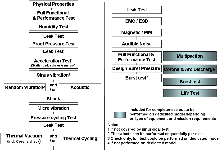 Figure 51: Space segment equipment test sequence
Qualification tests requirements
The space segment equipment qualification test baseline shall consist of the tests specified in Table 51 in line with requirement 5.1b, according to the type of the space segment equipment.
Table 51: Space segment equipment - Qualification test baseline
|
Test
|
Reference clause
|
Ref. to Level & Duration
|
Applicability versus types of space segment equipment
|
Application notes
| ||||||||||||||||
|
a
|
b
|
c
|
d
|
e
|
f
|
g
|
h
|
i
|
j
|
k
|
l
|
|
||||||||
|
General
|
|
|
|
|
|
|
|
|
|
|
|
|
|
|
|
|||||
|
Functional and performance (FFT/RFT)
|
5.5.1.1
|
|
R
|
R
|
R
|
R
|
R
|
R
|
R
|
R
|
R
|
R
|
R
|
R
|
For k (solar array), the deployment test is mandatory before and after the environmental tests (manual deployment before the environmental tests).
| |||||
|
Humidity
|
5.5.1.2
|
|
X
|
X
|
X
|
X
|
X
|
X
|
X
|
X
|
X
|
X
|
-
|
X
|
For k (solar array) and l (solar panel), see ECSS-E-ST-20-08.
| |||||
|
Life
|
5.5.1.3
|
See Table 52 No 1
|
X
|
X
|
R
|
R
|
X
|
X
|
R
|
X
|
X
|
R
|
-
|
-
|
To be performed on dedicated model.
| |||||
|
Burn-in
|
5.5.1.4
|
|
X
|
-
|
-
|
X
|
-
|
-
|
X
|
-
|
-
|
-
|
-
|
-
|
The test is performed in parallel with other funct. & environm. tests.
| |||||
|
Mechanical
|
|
|
|
|
|
|
|
|
|
|
|
|
|
|
|
|||||
|
Physical properties
|
5.5.2.1
|
|
R
|
R
|
R
|
R
|
R
|
R
|
R
|
R
|
R
|
R
|
R
|
R
|
Upon agreement with customer the CoG and MoI is not measured by test but calculated.
| |||||
|
Static load
|
5.5.2.2
|
See Table 52 No 2
|
X
|
X
|
X
|
X
|
X
|
X
|
X
|
X
|
X
|
X
|
X
|
-
|
One of the three types of test is performed if not covered by the sinusoidal vibration test.
| |||||
|
Spin
|
5.5.2.2
|
See Table 52 No 3
|
X
|
X
|
X
|
X
|
X
|
X
|
X
|
X
|
X
|
X
|
X
|
-
| ||||||
|
Transient
|
5.5.2.2
|
See Table 52 No 4
|
X
|
X
|
X
|
X
|
X
|
X
|
X
|
X
|
X
|
X
|
X
|
-
| ||||||
|
Random vibration
|
5.5.2.3
|
See Table 52 No 5
|
R
|
X
|
R
|
R
|
R
|
R
|
R
|
R
|
X
|
X
|
X
|
-
|
For k (solar array), the random vibration test should be added to acoustic test for fixed solar array mounted directly to the spacecraft side wall (without offset bracket).
| |||||
|
Acoustic
|
5.5.2.4
|
See Table 52 No 6
|
-
|
X
|
-
|
-
|
-
|
-
|
-
|
-
|
X
|
X
|
R
|
-
| ||||||
|
Sinusoidal vibration
|
5.5.2.5
|
See Table 52 No 7
|
R
|
R
|
R
|
R
|
R
|
R
|
R
|
R
|
R
|
R
|
R
|
-
|
|
|||||
|
Shock
|
5.5.2.6
|
See Table 52 No 8
|
R
|
X
|
R
|
R
|
R
|
X
|
R
|
X
|
R
|
R
|
-
|
-
|
If it is demonstrated that the susceptibility to shock of the space segment equipment is above the shock environment, the test needs not to be performed.
| |||||
|
Micro-vibration generated environment
|
5.5.2.7
|
|
X
|
X
|
-
|
X
|
X
|
-
|
X
|
-
|
-
|
X
|
-
|
-
|
Test to be performed only if need is identified by analysis.
| |||||
|
Micro-vibration susceptibility
|
5.5.2.8
|
See Table 52 No 9
|
X
|
-
|
-
|
-
|
-
|
-
|
-
|
-
|
X
|
X
|
-
|
-
|
Test to be performed only if need is identified by analysis.
| |||||
|
Structural integrity
|
|
|
|
|
|
|
|
|
|
|
|
|
|
|
|
|||||
|
Leak
|
5.5.3.1
|
See Table 52 No 10
|
X
|
-
|
R
|
R
|
R
|
R
|
X
|
X
|
-
|
-
|
-
|
-
|
Leak and pressure tests may be combined.
| |||||
|
Proof pressure
|
5.5.3.2
|
See Table 52 No 11
|
X
|
-
|
-
|
R
|
R
|
R
|
R
|
-
|
-
|
-
|
-
|
-
| ||||||
|
Pressure cycling
|
5.5.3.3
|
See Table 52 No 12
|
X
|
-
|
-
|
R
|
R
|
R
|
R
|
-
|
-
|
-
|
-
|
-
| ||||||
|
Design burst pressure
|
5.5.3.4
|
See Table 52 No 13
|
X
|
-
|
-
|
R
|
R
|
R
|
R
|
-
|
-
|
-
|
-
|
-
|
|
|||||
|
Burst
|
5.5.3.5
|
See Table 52 No 14
|
X
|
-
|
-
|
R
|
R
|
R
|
R
|
-
|
-
|
-
|
-
|
-
|
To be performed on dedicated model or at the end of the QM programme.
| |||||
|
Thermal
|
|
|
|
|
|
|
|
|
|
|
|
|
|
|
|
|||||
|
Thermal vacuum
|
5.5.4.1 & 5.5.4.2
|
See Table 52 No 15
|
R
|
X
|
R
|
R
|
R
|
X
|
R
|
R
|
R
|
R
|
-
|
R
|
|
|||||
|
Thermal ambient
|
5.5.4.1 & 5.5.4.3
|
See Table 52 No 16
|
R
|
X
|
R
|
R
|
R
|
X
|
R
|
R
|
R
|
R
|
-
|
-
|
For l (solar panels), the thermal tests at ambient pressure are applicable only to the DVT (Design Verification Test) coupon - see ECSS-E-ST-20-08).
| |||||
|
Electrical / RF
|
|
|
|
|
|
|
|
|
|
|
|
|
|
|
|
|||||
|
EMC
|
5.5.5.1
|
See Table 52 No 17
|
R
|
X
|
X
|
X
|
X
|
X
|
X
|
X
|
X
|
X
|
X
|
X
|
For equipment without electronic test are limited to Bonding test.
| |||||
|
Magnetic
|
5.5.5.2
|
|
X
|
X
|
X
|
X
|
X
|
X
|
X
|
X
|
X
|
X
|
X
|
X
|
Magnetic test to be performed if justified by mission needs, in accordance with the EMCCP.
| |||||
|
ESD
|
5.5.5.3
|
See Table 52 No 19
|
R
|
X
|
X
|
X
|
X
|
X
|
X
|
X
|
X
|
X
|
X
|
X
|
For k (solar array) and l (solar panels), the ESD test is covered by the ECSS-E-ST-20-08.
| |||||
|
PIM
|
5.5.5.4
|
See Table 52 No 19
|
X
|
X
|
-
|
-
|
-
|
-
|
-
|
-
|
-
|
-
|
-
|
-
|
|
|||||
|
Multipaction
|
5.5.5.5
|
|
X
|
X
|
-
|
-
|
-
|
-
|
-
|
-
|
-
|
-
|
-
|
-
|
To be performed on dedicated model.
| |||||
|
and arc discharge
|
5.5.5.6
|
See Table 52 No 20
|
R
|
R
|
R
|
-
|
-
|
-
|
-
|
-
|
-
|
-
|
-
|
-
|
To be performed on dedicated model.
| |||||
|
specific
|
|
|
|
|
|
|
|
|
|
|
|
|
|
|
|
|||||
|
Audible noise
|
5.5.6.1
|
|
R
|
-
|
-
|
R
|
R
|
-
|
R
|
-
|
-
|
R
|
-
|
-
|
Required for space segment equipment for crewed space segment element.
| |||||
|
Types of space segment equipment
|
Key
| |||||||||||||||||||
|
a Electronic, electrical and RF equipment
|
d Valve
|
g Thruster
|
j Mechanism
|
R Required
| ||||||||||||||||
|
NOTE 1: Tests are categorized into “R” or “X” depending on the sensitivity of the space segment equipment type to the specific environment, the probability of encountering the environment, and project specificity.
| ||||||||||||||||||||
Table 52: Space segment equipment - Qualification test levels and duration
|
No
|
Test
|
Levels
|
Duration
|
Number of applications
|
NOTES
|
|
1
|
Life
|
Expected environment and maximum operational load
|
For duration and cycles:
|
1 test
|
|
|
2
|
Static load
|
KQ x Limit Load
|
As needed to record data (10 seconds minimum)
|
Worst combined load cases
|
Worst combined load cases are determined by analysis
|
|
3
|
Spin
|

x spin rate
|
As specified by the project
|
1 test
|
|
|
4
|
Transient
|
KQ x Limit Load
|
As needed to record data
|
As specified
|
|
|
5
|
Random vibration
|
Maximum expected spectrum +3 dB on PSD values
|
2 minutes
|
On each of 3 orthogonal axes
|
|
|
6
|
Acoustic
|
Maximum expected acoustic spectrum +3 dB
|
2 minutes
|
1 test
|
|
|
7
|
Sinusoidal vibration
|
KQ x Limit Load Spectrum
|
sweep at 2 Oct/min,
|
On each of 3 orthogonal axes
|
|
|
8
|
Shock
|
Maximum expected shock spectrum +3 dB qualification margin
|
Duration representative of the expected environment
|
The number of shock application covering the complete life cycle of the FM H/W in all 3 orthogonal axes.
|
NOTE 1: Qualification programme test of space segment elements can include a test where the shock generative device is activated. This test is performed with no margins to consolidate the shock specification of the space segment equipment.
|
|
9
|
Microvibration susceptibility
|
Maximum predicted environment
|
As needed for susceptibility determination
|
As specified by the project.
|
|
|
10
|
Leak
|
MDP
|
pressure maintained for 30 minutes as minimum
|
In conformance with Figure 51.
|
|
|
11
|
Proof pressure
|
jproof x MDP
|
5 minutes minimum hold time
|
The number of pressure application covering the complete life cycle of the FM HW.
|
|
|
12
|
Pressure cycling
|
MDP
|
50 cycles or 4 x the number of planned pressure cycles expected in one service life, whichever is greater
|
1 test
|
|
|
13
|
Design burst pressure
|
jburst x MDP
|
30 seconds as minimum
|
1 test
|
|
|
14
|
Burst
|
Pressure increased until burst occurs
|
Until burst occurs
|
1 test
|
On dedicated model or on QM (if performed on QM, this destructive test will be the last test to be done)
|
|
15
|
Thermal vacuum
|

 Lower qualification margin than +/-5 C may be used for temperature below -170 C.
|
8 cycles
|
1 test
|
Note 1: Thermal vacuum and thermal ambient tests are both performed for space segment equipment that operate under a non-vacuum environment after having been exposed to vacuum.
|
|
16
|
Thermal ambient
|

 Lower qualification margin than +/-5 C may be used for temperature below -170 C.
|
8 cycles (See note 2)
|
1 test
|
Note 1: Ambient pressure depends on the type of mission (i.e. Mars mission, Venus mission)
|
|
17
|
EMC
|
See ECSS-E-ST-20-07 clause 5.4
|
See ECSS-E-ST-20-07 Clause 5.4
|
1 test
|
|
|
18
|
ESD
|
See ECSS-E-ST-20-06
|
See ECSS-E-ST-20-06
|
1 test
|
|
|
19
|
Passive Intermodulation
|
See ECSS-E-ST-20 clause 7.4
|
|
See ECSS-E-ST-20 clause 7.4
|
|
|
20
|
and arc discharge
|
Maximum operational voltage and maximum RF output power for RF equipment
|
10 to 15 minutes
|
1 test
|
For a given frequency, minimum gap within the space segment equipment, and given pressure a Paschen curve is defined. This curve has a minimum of power within the pressure range.
|
|
NOTE: The table does not include tests for some ambient conditions such as humidity and toxic-off gassing because they are performed exposing the hardware to the environment without margin.
| |||||
Acceptance test requirements
The space segment equipment acceptance test baseline shall consist of the tests specified in Table 53 in line with requirement 5.1b, according to the type of the space segment equipment.
Table 53: Space segment equipment - Acceptance test baseline
|
Test
|
Reference clause
|
Ref. to Level & Duration
|
Applicability versus types of space segment equipment
|
Application notes
| |||||||||||||||
|
a
|
b
|
c
|
d
|
e
|
f
|
g
|
h
|
i
|
j
|
k
|
l
|
|
|||||||
|
General
|
|
|
|
|
|
|
|
|
|
|
|
|
|
|
|
||||
|
Functional and performance (FFT/RFT)
|
5.5.1.1
|
|
R
|
R
|
R
|
R
|
R
|
R
|
R
|
R
|
R
|
R
|
R
|
R
|
For k (solar array), the deployment test is mandatory before and after the environmental tests (manual deployment before the environmental tests).
| ||||
|
Humidity
|
|
|
-
|
-
|
-
|
-
|
-
|
-
|
-
|
-
|
-
|
-
|
-
|
-
|
|
||||
|
Life
|
|
|
-
|
-
|
-
|
-
|
-
|
-
|
-
|
-
|
-
|
-
|
-
|
-
|
|
||||
|
Burn-in
|
5.5.1.4
|
|
X
|
-
|
-
|
X
|
-
|
-
|
X
|
-
|
-
|
-
|
-
|
-
|
To be performed, if the total duration of the acceptance test sequence is insufficient to detect material and workmanship defect occurring in the space segment equipment lifetime.
| ||||
|
Mechanical
|
|
|
|
|
|
|
|
|
|
|
|
|
|
|
|
||||
|
Physical properties
|
5.5.2.1
|
|
R
|
R
|
R
|
R
|
R
|
R
|
R
|
R
|
R
|
R
|
R
|
R
|
Upon agreement with customer the CoG and MoI is not measured by test. but calculated.
| ||||
|
Static load
|
|
|
-
|
-
|
-
|
-
|
-
|
X
|
-
|
-
|
-
|
-
|
-
|
-
|
General structural proof test is performed on pressure vessel if no covered by higher level test (e.g. sinusoidal with full tanks).
| ||||
|
Spin
|
|
|
-
|
-
|
-
|
-
|
-
|
-
|
-
|
-
|
-
|
-
|
-
|
-
| |||||
|
Transient
|
|
|
-
|
-
|
-
|
-
|
-
|
-
|
-
|
-
|
-
|
-
|
-
|
-
| |||||
|
Random vibration
|
5.5.2.3
|
See Table 54 No 1
|
R
|
X
|
R
|
R
|
R
|
R
|
R
|
R
|
X
|
X
|
X
|
-
|
For k (solar array), the random vibration test should be added to acoustic test for fixed solar array mounted directly to the spacecraft side wall (without offset bracket).
| ||||
|
Acoustic
|
5.5.2.4
|
See Table 54 No 2
|
-
|
X
|
-
|
-
|
-
|
-
|
-
|
-
|
X
|
X
|
R
|
-
| |||||
|
Sinusoidal vibration
|
5.5.2.5
|
See Table 54 No 3
|
-
|
-
|
-
|
-
|
-
|
-
|
-
|
-
|
-
|
-
|
R
|
-
|
For k (solar array), sinusoidal vibration acceptance testing of recurrent FMs (from the second FM) can be omitted on condition that they are subjected to acceptance testing at space segment element level, or in case of significant flight heritage on design, processes and manufacturers.
| ||||
|
Shock
|
|
|
-
|
-
|
-
|
-
|
-
|
-
|
-
|
-
|
-
|
-
|
-
|
-
|
|
||||
|
Micro-vibration generated environment
|
|
|
-
|
-
|
-
|
-
|
-
|
-
|
-
|
-
|
-
|
-
|
-
|
-
|
|
||||
|
Micro-vibration suscep.
|
5.5.2.8
|
See Table 54 No 4
|
X
|
-
|
-
|
-
|
-
|
-
|
-
|
-
|
X
|
X
|
-
|
-
|
Test to be performed only if need is identified by analysis.
| ||||
|
Structural integrity
|
|
|
|
|
|
|
|
|
|
|
|
|
|
|
|
||||
|
Leak
|
5.5.3.1
|
See Table 54 No 5
|
X
|
-
|
R
|
R
|
R
|
R
|
X
|
-
|
-
|
-
|
-
|
-
|
For a (electronic, electrical and RF equipment) required only on sealed or pressurized space segment equipment.
| ||||
|
Proof pressure
|
5.5.3.2
|
See Table 54 No 6
|
-
|
-
|
-
|
R
|
R
|
R
|
X
|
-
|
-
|
-
|
-
|
-
| |||||
|
Pressure cycling
|
|
|
-
|
-
|
-
|
-
|
-
|
-
|
-
|
-
|
-
|
-
|
-
|
-
|
|
||||
|
Design burst pressure
|
|
|
-
|
-
|
-
|
-
|
-
|
-
|
-
|
-
|
-
|
-
|
-
|
-
|
|
||||
|
Burst
|
|
|
-
|
-
|
-
|
-
|
-
|
-
|
-
|
-
|
-
|
-
|
-
|
-
|
|
||||
|
Thermal
|
|
|
|
|
|
|
|
|
|
|
|
|
|
|
|
||||
|
Thermal vacuum
|
5.5.4.1 & 5.5.4.2
|
See Table 54 No 7
|
R
|
X
|
R
|
R
|
R
|
X
|
R
|
R
|
R
|
R
|
-
|
R
|
|
||||
|
Thermal ambient
|
5.5.4.1 & 5.5.4.3
|
See Table 54 No 8
|
R
|
X
|
R
|
R
|
R
|
X
|
R
|
R
|
R
|
R
|
-
|
-
|
Can be combined in thermal vacuum test.
| ||||
|
Electrical / RF
|
|
|
|
|
|
|
|
|
|
|
|
|
|
|
|
||||
|
EMC
|
5.5.5.1
|
See Table 54 No 9
|
R
|
X
|
X
|
X
|
X
|
X
|
X
|
X
|
X
|
X
|
X
|
X
|
For equipment without electronic test are limited to bonding test.
| ||||
|
Magnetic
|
5.5.5.2
|
|
X
|
X
|
X
|
X
|
X
|
X
|
X
|
X
|
X
|
X
|
-
|
X
|
Magnetic test to be performed if justified by mission needs, in accordance with the EMCCP.
| ||||
|
ESD
|
|
|
-
|
-
|
-
|
-
|
-
|
-
|
-
|
-
|
-
|
-
|
-
|
-
|
|
||||
|
PIM
|
5.5.5.4
|
See Table 54 No 10
|
X
|
X
|
-
|
-
|
-
|
-
|
X
|
-
|
X
|
-
|
-
|
-
|
|
||||
|
Multipaction
|
5.5.5.5
|
|
X
|
X
|
-
|
-
|
-
|
-
|
-
|
-
|
-
|
-
|
-
|
-
|
|
||||
|
and arc discharge
|
5.5.5.6
|
See Table 54 No 11
|
R
|
R
|
R
|
-
|
-
|
-
|
-
|
-
|
-
|
-
|
-
|
-
|
For condition of applicability of test, refer to 5.5.5.6.
| ||||
|
specific
|
|
|
|
|
|
|
|
|
|
|
|
|
|
|
|
||||
|
Audible noise
|
5.5.6.1
|
|
R
|
R
|
-
|
R
|
R
|
-
|
R
|
-
|
-
|
R
|
-
|
-
|
Required for space segment equipment for crewed space segment element.
| ||||
|
Types of space segment equipment
|
Key
| ||||||||||||||||||
|
a Electronic, electrical and RF equipment
|
d Valve
|
g Thruster
|
j Mechanism
|
R Required
| |||||||||||||||
|
NOTE 1: Tests are categorized into “R” or “X” depending on the sensitivity of the space segment equipment type to the specific environment, the probability of encountering the environment, and project specificity.
| |||||||||||||||||||
Table 54: Space segment equipment - Acceptance test levels and duration
|
No
|
Test
|
Levels
|
Duration
|
Number of applications
|
NOTES
|
|
1
|
Random vibration
|
Maximum expected spectrum +0dB on PSD values
|
1 minute
|
On each of 3 orthogonal axes
|
|
|
2
|
Acoustic
|
Maximum expected acoustic spectrum +0dB
|
1 minute
|
1 test
|
|
|
3
|
Sinusoidal vibration
|
KA x Limit Load Spectrum
|
Sweep at 4 Oct/min,
|
On each of 3 orthogonal axes
|
|
|
4
|
Microvibration susceptibility
|
Maximum predicted environment
|
As needed for susceptibility determination
|
As specified by the project.
|
|
|
5
|
Leak
|
MDP
|
Pressure maintained for 30 minutes as minimum
|
In conformance with Figure 51
|
|
|
6
|
Proof pressure
|
jproof x MDP
|
5 minutes minimum hold time
|
1
|
|
|
7
|
Thermal vacuum
|


Lower acceptance margin than +/-5 C, may be used for temperature below -170 C.
|
4 cycles
|
1 test
|
Note 1: Thermal vacuum and thermal ambient tests are both performed for space segment equipment that operate under a non-vacuum environment after having been exposed to vacuum.
|
|
8
|
Thermal ambient
|

Lower acceptance margin than +/-5 C may be used for temperature below -170 C.
|
4 cycles (See Note 2)
|
1 test
|
Note 1: Ambient pressure depends on the type of mission (i.e. Mars mission, Venus mission)
|
|
9
|
EMC
|
Apply ECSS-E-ST-20-07 clause 5.4
|
Apply ECSS-E-ST-20-07 Clause 5.4
|
1 test
|
|
|
10
|
Passive intermodulation
|
For equipment see ECSS-E-ST-20 clause 7.4
|
|
See ECSS-E-ST-20 clause 7.4
|
|
|
11
|
and Arc discharge
|
Maximum operational voltage and maximum RF output power for RF equipment
|
10 to 15 minutes
|
1 test
|
For a given frequency, minimum gap within the space segment equipment, and given pressure a Paschen curve is defined. This curve has a minimum of power within the pressure range.
|
|
NOTE: The table does not include tests for some ambient conditions such as humidity and toxic-off gassing because they are performed exposing the hardware to the environment without margin.
| |||||
Protoflight test requirements
The space segment equipment Protoflight test baseline shall consist of the tests specified in Table 55 in line with requirement 5.1b, according to the type of the space segment equipment.
The following qualification tests shall be performed on a dedicated model and never on the Protoflight Model:
- life test
- burst pressure test,
- ESD. Table 55: Space segment equipment - Protoflight test baseline
|
Test
|
Reference clause
|
Ref. to Level & Duration
|
Applicability versus types of space segment equipment
|
Application notes
| |||||||||||||||
|
a
|
b
|
c
|
d
|
e
|
f
|
g
|
h
|
i
|
j
|
k
|
l
|
|
|||||||
|
General
|
|
|
|
|
|
|
|
|
|
|
|
|
|
|
|
||||
|
Functional and performance (FFT/RFT)
|
5.5.1.1
|
|
R
|
R
|
R
|
R
|
R
|
R
|
R
|
R
|
R
|
R
|
R
|
R
|
For k (solar array), the deployment test is mandatory before and after the environmental tests (manual deployment before the environmental tests).
| ||||
|
Humidity
|
5.5.1.2
|
|
X
|
X
|
X
|
X
|
X
|
X
|
X
|
X
|
X
|
X
|
-
|
X
|
For k (solar array) and l (solar panel), see ECSS-E-ST-20-08.
| ||||
|
Life
|
5.5.1.3
|
See Table 56 No 1
|
X
|
X
|
R
|
R
|
X
|
X
|
R
|
X
|
X
|
R
|
-
|
-
|
To be performed on dedicated model.
| ||||
|
Burn-in
|
5.5.1.4
|
|
X
|
-
|
-
|
X
|
-
|
-
|
X
|
-
|
-
|
-
|
-
|
-
|
The test is performed in parallel with other funct. & environm. tests.
| ||||
|
Mechanical
|
|
|
|
|
|
|
|
|
|
|
|
|
|
|
|
||||
|
Physical properties
|
5.5.2.1
|
|
R
|
R
|
R
|
R
|
R
|
R
|
R
|
R
|
R
|
R
|
R
|
R
|
Upon agreement with customer the CoG and MoI is not measured by test. but calculated.
| ||||
|
Static load
|
|
|
-
|
-
|
-
|
-
|
-
|
-
|
-
|
-
|
-
|
-
|
-
|
-
|
|
||||
|
Spin
|
5.5.2.2
|
See Table 56 No 2
|
X
|
X
|
X
|
X
|
X
|
X
|
X
|
X
|
X
|
X
|
X
|
-
|
One of the two types of test is performed if not covered by the sinusoidal vibration test.
| ||||
|
Transient
|
5.5.2.2
|
See Table 56 No 3
|
X
|
X
|
X
|
X
|
X
|
X
|
X
|
X
|
X
|
X
|
X
|
-
| |||||
|
Random vibration
|
5.5.2.3
|
See Table 56 No 4
|
R
|
X
|
R
|
R
|
R
|
R
|
R
|
R
|
X
|
X
|
X
|
-
|
For k (solar array), the random vibration test should be added to acoustic test for fixed solar array mounted directly to the spacecraft side wall (without offset bracket).
| ||||
|
Acoustic
|
5.5.2.4
|
See Table 56 No 5
|
-
|
X
|
-
|
-
|
-
|
-
|
-
|
-
|
X
|
X
|
R
|
-
| |||||
|
Sinusoidal vibration
|
5.5.2.5
|
See Table 56 No 6
|
R
|
R
|
R
|
R
|
R
|
R
|
R
|
R
|
R
|
R
|
R
|
-
|
|
||||
|
Shock
|
5.5.2.6
|
See Table 56 No 7
|
R
|
X
|
R
|
R
|
R
|
X
|
R
|
X
|
R
|
R
|
-
|
-
|
If it is demonstrated that the susceptibility to shock of the space segment equipment is above the shock environment, the test needs not to be performed.
| ||||
|
Micro-vibration generated environment
|
5.5.2.7
|
|
X
|
X
|
-
|
X
|
X
|
-
|
X
|
-
|
-
|
X
|
-
|
-
|
Test to be performed only if need is identified by analysis.
| ||||
|
Micro-vibration susceptibility
|
5.5.2.8
|
See Table 56 No 8
|
X
|
-
|
-
|
-
|
-
|
-
|
-
|
-
|
X
|
X
|
-
|
-
|
Test to be performed only if need is identified by analysis.
| ||||
|
Structural integrity
|
|
|
|
|
|
|
|
|
|
|
|
|
|
|
|
||||
|
Leak
|
5.5.3.1
|
See Table 56 No 9
|
X
|
-
|
R
|
R
|
R
|
R
|
X
|
X
|
-
|
-
|
-
|
-
|
Leak and pressure tests may be combined.
| ||||
|
Proof pressure
|
5.5.3.2
|
See Table 56 No 10
|
X
|
-
|
-
|
R
|
R
|
R
|
R
|
-
|
-
|
-
|
-
|
-
| |||||
|
Pressure cycling
|
|
|
-
|
-
|
-
|
-
|
-
|
-
|
-
|
-
|
-
|
-
|
-
|
-
|
|
||||
|
Design burst pressure
|
|
|
-
|
-
|
-
|
-
|
-
|
-
|
-
|
-
|
-
|
-
|
-
|
-
|
|
||||
|
Burst
|
|
|
-
|
-
|
-
|
-
|
-
|
-
|
-
|
-
|
-
|
-
|
-
|
-
|
|
||||
|
Thermal
|
|
|
|
|
|
|
|
|
|
|
|
|
|
|
|
||||
|
Thermal vacuum
|
5.5.4.1 & 5.5.4.2
|
See Table 56 No 11
|
R
|
X
|
R
|
R
|
R
|
X
|
R
|
R
|
R
|
R
|
-
|
R
|
|
||||
|
Thermal ambient
|
5.5.4.1 & 5.5.4.3
|
See Table 56 No 12
|
R
|
X
|
R
|
R
|
R
|
X
|
R
|
R
|
R
|
R
|
-
|
-
|
For l (solar panels), the thermal tests at ambient pressure are applicable only to the DVT (Design Verification Test) coupon - see ECSS-E-ST-20-08).
| ||||
|
Electrical / RF
|
|
|
|
|
|
|
|
|
|
|
|
|
|
|
|
||||
|
EMC
|
5.5.5.1
|
See Table 56 No 13
|
R
|
X
|
X
|
X
|
X
|
X
|
X
|
X
|
X
|
X
|
X
|
X
|
For equipment without electronic test are limited to bonding test.
| ||||
|
Magnetic
|
5.5.5.2
|
|
X
|
X
|
X
|
X
|
X
|
X
|
X
|
X
|
X
|
X
|
X
|
X
|
Magnetic test to be performed if justified by mission needs, in accordance with the EMCCP.
| ||||
|
ESD
|
5.5.5.3
|
See Table 56 No 14
|
R
|
X
|
X
|
X
|
X
|
X
|
X
|
X
|
X
|
X
|
X
|
X
|
To be performed on dedicated model.
| ||||
|
PIM
|
5.5.5.4
|
See Table 56 No 15
|
X
|
X
|
-
|
-
|
-
|
-
|
-
|
-
|
-
|
-
|
-
|
-
|
|
||||
|
Multipaction
|
5.5.5.5
|
|
X
|
X
|
-
|
-
|
-
|
-
|
-
|
-
|
-
|
-
|
-
|
-
|
To be performed on dedicated model.
| ||||
|
and arc discharge
|
5.5.5.6
|
See Table 56 No 16
|
R
|
R
|
R
|
-
|
-
|
-
|
-
|
-
|
-
|
-
|
-
|
-
|
To be performed on dedicated model.
| ||||
|
specific
|
|
|
|
|
|
|
|
|
|
|
|
|
|
|
|
||||
|
Audible noise
|
5.5.6.1
|
|
R
|
-
|
-
|
R
|
R
|
-
|
R
|
-
|
-
|
R
|
-
|
-
|
Required for space segment equipment for crewed space segment element.
| ||||
|
Types of space segment equipment
|
Key
| ||||||||||||||||||
|
a Electronic, electrical and RF equipment
|
d Valve
|
g Thruster
|
j Mechanism
|
R Required
| |||||||||||||||
|
NOTE 1: Tests are categorized into “R” or “X” depending on the sensitivity of the space segment equipment type to the specific environment, the probability of encountering the environment, and project specificity.
| |||||||||||||||||||
Table 56: Space segment equipment - Protoflight test levels and duration
|
No
|
Test
|
Levels
|
Duration
|
Number of applications
|
NOTES
|
|
1
|
Life
|
Expected environment and maximum operational load
|
For duration and cycles:
|
1 test
|
|
|
2
|
Spin
|

x spin rate
|
As needed to record data
|
On each of 3 orthogonal axes
|
|
|
3
|
Transient
|
KQ x Limit Load
|
As needed to record data
|
As specified
|
|
|
4
|
Random vibration
|
Maximum expected spectrum +3 dB on PSD values
|
1 minute
|
On each of 3 orthogonal axes
|
|
|
5
|
Acoustic
|
Maximum expected acoustic spectrum +3 dB
|
1 minute
|
1 test
|
|
|
6
|
Sinusoidal vibration
|
KQ x Limit Load Spectrum
|
sweep at 4 Oct/min,
|
On each of 3 orthogonal axes
|
|
|
7
|
Shock
|
Maximum expected shock spectrum +3 dB margin
|
As specified by the project.
|
1 test
|
NOTE 1: Qualification programme test of space segment elements can include a test where the shock generative device is activated. This test is performed with no margins to consolidate the shock specification of the space segment equipment.
|
|
8
|
Microvibration susceptibility
|
Maximum predicted environment
|
As needed for susceptibility determination
|
As specified by the project.
|
|
|
9
|
Leak
|
MDP
|
Pressure maintained for 30 minutes as minimum
|
In conformance with Figure 51.
|
|
|
10
|
Proof pressure
|
jproof x MDP
|
5 minutes minimum hold time
|
1 test
|
|
|
11
|
Thermal vacuum
|

 Lower qualification margin than +/-5C may be used for temperature below -170 C.
|
4 cycles
|
1 test
|
Note 1: Thermal vacuum and thermal ambient tests are both performed for space segment equipment that operate under a non-vacuum environment after having been exposed to vacuum.
|
|
12
|
Thermal ambient
|

 Lower qualification margin than +/-5 C may be used for temperature below -170 C.
|
4 cycles (See note 2)
|
1 test
|
Note 1: Ambient pressure depends on the type of mission (i.e. Mars mission, Venus mission)
|
|
13
|
EMC
|
See ECSS-E-ST-20-07 clause 5.4
|
See ECSS-E-ST-20-07 clause 5.4
|
1 test
|
|
|
14
|
ESD
|
See ECSS-E-ST-20-06
|
See ECSS-E-ST-20-06
|
1 test
|
|
|
15
|
Passive Intermodulation
|
See ECSS-E-ST-20 clause 7.4
|
|
See ECSS-E-ST-20 clause 7.4
|
|
|
16
|
and arc discharge
|
Maximum operational voltage and maximum RF output power for RF equipment
|
10 to 15 minutes
|
1 test
|
For a given frequency, minimum gap within the space segment equipment, and given pressure a Paschen curve is defined. This curve has a minimum of power within the pressure range.
|
|
NOTE: The table does not include tests for some ambient conditions such as humidity and toxic-off gassing because they are performed exposing the hardware to the environment without margin.
| |||||
Space segment equipment test programme implementation requirements
General tests
Functional and performance tests
Functional tests shall verify the complete function of the space segment equipment, under the specified operating and environment conditions and in all operational modes.
Performance tests shall verify that the space segment equipment performances, under the specified environment, are compliant with the performances specification.
Functional and performance test may be combined as single test depending on their complexity and time duration.
In this case the test is called functional and performance test.
In case of internal redundancy, functional tests shall be performed on both chains taking into account the type of redundancy (e.g. hot or cold).
In case of cross-strapped configurations, requirements for testing shall be agreed with the customer.
Test parameters shall be varied throughout their specification ranges and the sequences expected in flight operation.
Electrical tests shall include application of expected voltages, impedance, frequencies, pulses, and wave forms at the electrical interface of the space segment equipment, including all redundant circuits if any.
For antennas the electrical interface is understood to include the far field radiation pattern.
Electrical test shall include the measurement of the electrical properties at the interfaces as specified in the ICD.
For example, power consumption, inrush current, signal characteristics, response time, expected voltages, impedances frequencies, pulses and waves forms characteristic at the interfaces, including redundant circuits if any.
Fault voltage tolerance of interface circuit shall be tested to ensure absence of failure propagation risks.
When accessible, protection functions shall be tested.
Example of protection function are over-voltage, and over-current.
When protection function have the capability to be overwritten, the overwrite function shall be tested.
For the solar array, the performance tests shall include the flasher test.
Mechanical tests shall include application of torque, load and motion as specified.
When relevant, internal alignment shall be verified as part of the functional test.
Humidity test
If the space segment equipment can be exposed to humidity level above 65 % during its life time then a humidity qualification test shall be performed.
More information on humidity effects can be found in ECSS-Q-ST-70-01.
For qualification humidity test the space segment equipment shall be installed in the chamber and tested in accordance with the following processes and steps:
- Pretest Conditions. Keep the chamber temperature at room ambient conditions with uncontrolled humidity.
- Cycle 1. Perform the following process:
- Increase the temperature to +35 °C over a one hour period.
- Increase the humidity to not less than 95 % over a one hour period with the temperature maintained at +35 °C.
- Hold the conditions 5.5.1.2b.2(a) and 5.5.1.2b.2(b) for two hours.
- Reduced the temperature to +2 °C over a two hour period with the relative humidity stabilized at not less than 95 %.
- Hold conditions 5.5.1.2b.2(d) for two hours.
- Cycle 2. Repeat the foregoing cycle but increase the temperature from +2 C to +35 °C over a two hour period (moisture is not added to the chamber until +35 °C is reached).
- Cycle 3. Perform the following process:
- Increase the chamber temperature to +35 °C over a two hour period without adding any moisture to the chamber.
- Dry the test component with air at room temperature and 50 % maximum relative humidity by blowing air through the chamber for six hours.
- Set the volume of air used per minute equal to one to three times the test chamber volume.
A suitable container can be used in place of the test chamber for drying the test component.
- Cycle 4. Perform the following process:
- Place the space segment equipment in the test chamber and increase the temperature to +35 °C.
- Increase the relative humidity to 90 % over a one hour period.
- Maintain conditions 5.5.1.2b.5(a) and 5.5.1.2b.5(b) for at least one hour.
- Reduce the temperature to +2 °C over a one hour period with the relative humidity stabilized at 90 %.
- Maintain conditions 5.5.1.2b.5(d) for at least one hour.
- Follow the drying cycle (Cycle 3).
- Check the space segment equipment prior to the test and at the end of Cycle 3 (within 2 h after the drying) and visually inspect for deterioration or damage.
- Test the space segment equipment functionally during the Cycle 4 period of stability (i.e. following the 1 h-period after reaching +35 C and 90 % relative humidity conditions).
- Inspect the space segment equipment visually for deterioration or damage after removal from the chamber.
Life test
The life test for space segment equipment qualification shall be designed to demonstrate the ability of the space segment equipment to withstand the maximum operating time and the maximum number of predicted operational cycles during the “product lifetime” by providing the required performance at the end of life.
This test is performed on life-limited space segment equipment or part of it.
The space segment equipment shall be set up to operate under the environmental conditions expected during actual operation.
Environments include e.g. ambient, thermal, vacuum, and various combinations of these.
If the launch impacts the lifetime, test simulating the launch constraints shall be performed prior the lifetime test to ensure proper mechanical setting.
Examples of launch constraints are vibration, shock.
The space segment equipment shall be either selected at random from production lot or be the qualification space segment equipment.
The demonstration of the lifetime shall be performed in the expected environment, using the sum of the predicted nominal ground cycle and the in-orbit cycle plus the qualification margins.
- 1 For space segment equipment having a relatively low percentage duty cycle, it can be acceptable to compress the operational duty cycle to reduce the total test duration.
- 2 For space segment equipment that operate continuously in orbit, or at very high duty cycles, accelerated test techniques can be employed pending demonstration that this leads to realistic results and approval by the customer.
Performances shall be monitored continuously or at regular intervals.
All the components of an actuation chain shall be submitted to the same number of actuations.
Examples of such components are motors, bearing, and gears.
Burn-in test
The total operating time and temperature for electrical space segment equipment burn-in, shall be agreed with the customer.
- 1 Those parameters depend on the type of space segment equipment and of the level of test performed at components / subassembly level.
- 2 The time of operation in thermal testing is part of the burn in time.
Mechanical tests
Physical properties measurements
The following physical properties of space segment equipment shall be determined using tools and techniques that conform to the required accuracy:
- Dimensions and interfaces;
- Mass;
- Centre of gravity with respect to a given coordinate system for three mutually perpendicular axes;
- Momentum of inertia with respect to the given coordinate system.
For space segment equipment with simple shapes, the centre of gravity location and momenta of inertia can be determined by calculation.
The space segment equipment shall be in launch configuration, unless this configuration cannot be reproduced on ground.
Acceleration test (static, spin or transient)
The space segment equipment shall be mounted to a test fixture through its normal mounting points.
When a centrifuge is used, it shall be ensured that the length of the arm (measured to the geometric centre of the space segment equipment) is at least five times the dimension of the space segment equipment measured along the arm.
This is to ensure uniform force distribution on the space segment equipment.
Random vibration test
Random vibration tests shall be conducted in launch configuration for all axes.
The induced cross axis accelerations at the attachment points shall be limited to the maximum test levels specified for the cross axis.
In order to evaluate the space segment equipment integrity a resonance search shall be performed before and after the random vibration test.
The success criteria for the resonance search shall be:
- less than 5 % in frequency shift, for modes with an effective mass greater than 10 %;
- less than 20 % in amplitude shift, for modes with an effective mass greater than 10 %.
Detailed visual checks shall be carried out when functional tests are not performed.
For space segment equipment which is designed to be re-flown, the qualification test duration per axis shall be in conformance with Table 52 plus 50 seconds per additional flight.
Acoustic test
Acoustic tests shall be conducted in a reverberating chamber, with the space segment equipment in launch configuration mounted on a test fixture simulating the dynamic flight mounting conditions.
Acoustic tests are often but not always conducted on space segment equipment with large surfaces which are likely to be susceptible to acoustic noise excitations, e.g. solar arrays, antennas; for this type of space segment equipment random vibration testing is not performed.
The space segment equipment and the test fixture shall be decoupled from chamber floor and wall structure born vibration.
In order to evaluate the space segment equipment integrity a low level acoustic run (-8 dB the qualification level) shall be performed before and after the acoustic qualification run by determining resonant frequencies.
The success criteria for the resonance search shall be:
- less than 5 % in frequency shift, for modes with an effective mass greater than 10 %;
- less than 40 % in amplitude shift, for modes with an effective mass greater than 10 %. For space segment equipment which is designed to be re-flown, the qualification test duration shall be in conformance with Table 52 plus 50 seconds per additional flight.
Sinusoidal vibration test
Sinusoidal tests shall be conducted in the launch configurations for all axes.
A resonance search shall be performed before and after the sinusoidal vibration test to determine resonance frequencies to evaluate the space segment equipment integrity.
The success criteria for the resonance search shall be:
- less than 5 % in frequency shift, for modes with an effective mass greater than 10 %;
- less than 20 % in amplitude shift, for modes with an effective mass greater than 10 %.
Detailed visual checks shall be carried out prior and after test to check for visual damage.
The induced cross axis excitation shall be monitored to check that the response in the cross axis does not exceed the specification.
Shock test
Shock tests shall be conducted in the item under test configuration relevant to the event where the shock is produced.
The shock tests demonstrate the ability of the space segment equipment to withstand the shocks encountered during the lifetime, e.g.: fairing separation, space segment equipment separation, booster burn out, apogee boost motor ignition, solar arrays and antennas deployment, shocks from landing of reusable elements.
Equipment powered during the event where the shock is produced, shall be powered during the test.
The equipment shall be mounted to a fixture using its normal mounting points.
The selected test method shall achieve the specified Shock Response Spectrum with a representative transient, comparable in shape and duration to the expected in-flight shock.
To reduce the number of shock activations, axes and directions may be combined, provided the required environment is created.
Detailed visual checks shall be carried out.
Hardware integrity shall be verified after the test.
This is performed through several ways, like performance test, low level sinusoidal vibration pre and post test, modal survey, alignment.
The induced cross axis excitation shall be monitored to check that the response in the cross axis do not exceed the specification.
The homogeneity of the shock around the equipment under test shall be monitored by at least one pair of sensors mounted at opposite corners of the equipment.
Micro-vibration generated environment test
The measurements of the space segment equipment interface dynamic forces and torques shall be performed.
The space segment equipment shall be in its nominal operational configuration similar to the on-orbit operational conditions.
Micro-vibration susceptibility test
The performance parameters shall be measured when subjected to the maximum predicted micro-vibration environment.
The space segment shall be in its nominal operational configuration similar to the on-orbit operational conditions.
Structural integrity tests
Leak test
Leak tests shall be performed only on sealed or pressurized space segment equipment, sensitive to loss of pressure or vacuum.
The leak test shall demonstrate the ability of sealed or pressurized space segment equipment to conform to the leak rates stated in the specifications.
The leak test method employed shall have sensitivity and accuracy consistent with the space segment equipment specified maximum allowable leak rate.
The sensitivity of the leak test, in particular, shall be quantitatively less than the minimum leak rate to be detected by a factor of at least two to ensure reliability of measurements.
Leak tests shall be performed prior to and following the completion of space segment equipment thermal and mechanical tests.
Leak tests shall be conducted prior to and following proof pressure tests.
When temperature potentially affects the sealing materials or surfaces, an evaluation of the hardware design and operational characteristics shall be performed and, if technically warranted, the leak test conducted at the minimum and maximum qualification or acceptance temperature limits for respectively qualification or acceptance test.
If seals are dependent upon differential pressure for proper sealing, leak tests shall be performed with the space segment equipment pressurized at the maximum operating pressure and at the minimum operating pressure.
Proof pressure test
The proof pressure qualification test shall be performed to demonstrate absence of leak and permanent deformation.
The proof pressure acceptance test shall be performed to demonstrate absence of workmanship problem leading to leak above the specification.
The influence of temperature on test validity shall be in conformance with ECSS-E-ST-32-02 requirements 5.4.1c and 5.5.1b.
Pressure cycling test
Pressure cycling test shall be performed in conformance with ECSS-E-ST-32-02 clause 5.4.5.
The influence of temperature on test validity shall be taken into account by applying ECSS-E-ST-32-02 requirement 5.4.1c.
Design burst pressure test
The influence of temperature on test validity shall be taken into account by applying ECSS-E-ST-32-02 requirement 5.4.1c.
After burst pressure, no space segment equipment or any of its parts shall be used for further qualification activities or as flight hardware.
Burst test
Burst test shall be performed in conformance with ECSS-E-ST-32-02 clause 5.4.7.
Thermal tests
Requirements applicable to thermal vacuum and thermal ambient tests
Both thermal vacuum and thermal ambient tests shall be performed for space segment equipment that operate under a non-vacuum environment after having been exposed to vacuum.
For example, in the case of a planetary mission, the space segment equipment is tested in vacuum and in the mission atmosphere pressure.
Thermal balance phase(s), if required, shall be included in the thermal vacuum or thermal ambient test at a pressure value corresponding to the type of mission.
E.g. for very dissipative equipment, equipment with important thermal gradients at vacuum conditions, Earth atmospheric pressure, space station pressure or Mars pressure.
All space segment equipment temperatures shall refer to the temperature reference point.
The space segment equipment temperatures shall be defined for the following conditions:
- minimum and maximum operating qualification and acceptance;
- minimum and maximum non-operating qualification, and acceptance;
- minimum switch ON and maximum (as relevant).
The test level shall take into account the test tolerances as specified in Table 41.
The temperature rate of change shall be lower than 20 K per minute.
Functional test shall only start after a dwell time greater or equal to 2 hours.
Test profile, test configuration, number of cycles, extreme temperatures, temperature rate of change, stability criteria, dwell time duration, tests to be performed and success criteria shall be defined in the test specification.
The test profile shall include a non operating cycle.
The space segment equipment shall be subjected to functional test before and after the thermal test.
Functional tests shall be performed as a minimum at hot and cold operating temperatures.
Test during transition are subjected to case by case decision.
Cold (and as applicable Hot) switch on capabilities shall be demonstrated.
In case of internal redundancy, thermal tests shall be performed on both chains taking into account the type of redundancy (e.g. hot or cold).
In case of cross-strapped configurations, requirements for testing shall be agreed with the customer.
The space segment equipment operative configuration during the test shall be the most severe one in the power time domain and from the power consumption point of view.
Monitoring for corona shall be conducted during chamber pressure reduction for space segment equipment that are critical with regard to corona effect.
For thermal ambient test, this is justified by the fact that ambient pressure can be lower than Earth atmospheric pressure.
Test methods and test set-up shall be defined according to the thermal environment characteristics, the TCS thermal design and the space segment equipment itself.
The test set-up shall ensure appropriate orientation for space segment equipment containing two phases heat transport equipment (e.g. heat pipe).
This means that the two phases heat transport equipment is horizontal or works in reflux mode.
Requirements applicable to thermal vacuum test
Thermal vacuum testing shall be performed for space segment equipment whose operation occurs in space vacuum environment at any time of its lifetime.
Space segment equipment shall be tested at a pressure of 10-5 hPa or less.
Conditions and test set-up shall be such as to avoid contamination of the equipment.
In line with requirement 5.5.4.2c the test profile should start with a maximum non-operating temperature.
For solar array, continuity and insulation resistance shall be monitored during the test as per ECSS-E-ST-20-08 requirements 5.5.3.11.2 f and g.
Requirements applicable to thermal ambient test
Test approach with thermal ambient test without vacuum test shall be selected only for space segment equipment that operates under a non-vacuum environment during their entire lifetime.
In assessing this, depressurisation failure should be considered.
Pressure value for the thermal ambient test shall be as per type of mission.
E.g. Earth atmospheric pressure, space station pressure, Mars pressure.
Climatic conditions shall be such as to avoid condensation on the item under test.
The space segment equipment shall be mounted in a temperature chamber or in a vacuum chamber if the ambient pressure is different from the atmospheric pressure.
Electrical/RF tests
EMC test
The EMC test shall be performed in conformance with ECSS-E-ST-20-07 clause 5.
For acceptance stage, the space segment equipment shall be subjected to the following tests, as per ECSS-E-ST-20-07:
- bonding verification;
- power lines isolation;
- inrush current;
- conducted emission time domain (ripple and spikes) on power lines in the operating mode, which produces maximum emissions;
- conducted emission frequency domain on power lines in the operating mode, which produces maximum emissions.
For RF space segment equipment sniff or spray test shall be performed at one or several frequencies used by the space segment equipment under test or in mission critical receive bands.
Sniff or spray test should be performed with a guide to coax transitions at a controlled distance.
Magnetic test
The magnetic test shall be performed in conformance with ECSS-E-ST-20-07 clause 4.2.5 and 5.4.5.
ESD test
The ESD test on space segment equipment shall be performed in conformance with ECSS-E-ST-20-07 clause 5.4.12.
Passive intermodulation test
The passive intermodulation test shall be performed in conformance with ECSS‐E‐ST‐20.
Multipaction test
The multipaction test shall be performed in conformance with ECSS‐E‐20-01.
and arc discharge test
and arc discharge test shall be performed for space segment equipment exposed to the critical low pressure atmosphere according to relevant Paschen curves during its lifetime.
Demonstration of margin for corona and arc discharges effect is mainly achieved by analysis, and by component/ sub assembly or development model level test. During space segment element qualification programme, it is unlikely that margin can be applied (i.e. on voltage or output power for RF), the test is then limited to a go/nogo test.
specific test
Audible noise test
General
During the audible noise test the following measurements shall be performed:
- the space segment equipment sound power level transmitted via airborne,
- the space segment equipment sound power level induced by vibration through the mounting structure,
The total sound power delivered by the space segment equipment is the sum of two contributions: the sound power transmitted to the space segment element via airborne transmission path and via the mounting structure.
- the interface dynamic forcing functions of the disturbance source.
The space segment equipment shall be operated during airborne and structure borne noise measurements with the same modes as during the mission phases of the crewed space segment element.
The noise level and exposure time shall be given for each operational mode of the space segment equipment.
Equipment airborne sound pressure measurement
The space segment equipment sound power measurements shall be performed in accordance with ISO 3740:2000.
The sound power level shall be converted into cabin pressure level.
Structure-borne noise measurement
The sound power levels shall be converted into cabin pressure levels.
The space segment equipment interface disturbance force levels shall be measured both directly and indirectly.
Space segment element test requirements
General requirements
When it is not feasible to test a space segment element as a single entity, it may be tested separately as several space segment elements or space segment equipment.
- 1 For example, when it is not feasible due to its size, which can exceed the capacity of a test facility.
- 2 A satellite can be performed as service module on one end and as payload module test on the other.
The effects of item(s), which are interacting on the element level, but which are not present during tests, shall be included with the support of simulators.
Simulators can be fluid, mechanical, thermal, electrical item(s) or software.
The test baseline shall be tailored for each project.
The sequence of test shall be agreed by the customer depending on the nature of the space segment element and how performances are tested.
- 1 For Infrared instrument or satellite including IR instrument the TV test is the one that allows performance verification, in this case it is often the last test performed.
- 2 For RF radiometer the performance are verified in anechoic chamber, in this case the auto compatibility / Radiated EMC is often one of the last tests performed.
For space segment element undergoing a PFM approach, the equipment that are part of it, should be acceptance tested.
This implies that the equipment design is qualified on a QM.
Any unusual or unexpected behaviour shall be evaluated to determine the existence of any trend potentially leading to anomaly or failure situation.
Visual inspections shall be performed before and after each test.
Qualification test requirements
When a full Qualification model is developed for a space segment elements qualification the test baseline shall consist of the tests specified in Table 61.
Other special tests can be performed depending upon the project characteristics and product lifetime cycle.
Table 61: Space segment element - Qualification test baseline
|
Test
|
Reference clause
|
Ref. to Level & Duration & Number of applications
|
Applicability
|
Conditions
| |
|
General
|
|
||||
|
Optical alignment
|
6.5.1.1
|
|
R
|
|
|
|
Functional (FFT / RFT)
|
6.5.1.2
|
|
R
|
|
|
|
Performances (PT)
|
6.5.1.3
|
|
R
|
|
|
|
(MT)
|
6.5.1.4
|
|
R
|
|
|
|
Polarity
|
6.5.1.5
|
|
R
|
|
|
|
Launcher Interface
|
6.5.1.6
|
|
X
|
Mandatory for space segment element interfacing with launcher if not performed on FM (see Table 63).
| |
|
Mechanical
|
|
||||
|
Physical properties
|
6.5.2.1
|
|
R
|
|
|
|
Modal survey
|
6.5.2.2
|
|
X
|
|
|
|
Static
|
6.5.2.3
|
Table 62 No 1
|
X
|
Mandatory if not performed at structure subsystem level
| |
|
Spin
|
6.5.2.4
|
Table 62 No 2
|
X
|
Mandatory for spinning space segment elements with an acceleration greater than 2g or more to any part of the space segment element
| |
|
Transient
|
6.5.2.5
|
Table 62 No 3
|
X
|
|
|
|
Acoustic
|
6.5.2.6
|
Table 62 No 4
|
X
|
Acoustic test may be replaced by random vibration.
| |
|
Random vibration
|
6.5.2.7
|
Table 62 No 5
|
X
| ||
|
Sinusoidal vibration
|
6.5.2.8
|
Table 62 No 6
|
R
|
Sinusoidal vibration may be replaced by transient combined with modal survey
| |
|
Shock
|
6.5.2.9
|
Table 62 No 7
|
X
|
|
|
|
Micro-vibration susceptibility
|
6.5.2.10
|
Table 62 No 8
|
X
|
|
|
|
Structural Integrity
|
|
||||
|
Proof pressure
|
6.5.3.1
|
Table 62 No 9
|
X
|
Mandatory for pressurized space segment elements or on pressurized equipment integrated in space segment element for which the test is feasible
| |
|
Pressure Cycling
|
6.5.3.2
|
Table 62 No 10
|
X
|
Mandatory for Pressurized space segment elements that will experience several re-entries.
| |
|
Design Burst pressure
|
6.5.3.3
|
Table 62 No 11
|
X
|
Mandatory for pressurized space segment element may be performed on a dedicated hardware
| |
|
Leak
|
6.5.3.4
|
Table 62 No 12
|
X
|
Mandatory for pressurized space segment elements or on pressurized equipment integrated in space segment element for which the test is feasible
| |
|
Thermal
|
|
||||
|
Thermal vacuum
|
6.5.4.1 & 6.5.4.2
|
Table 62 No 13
|
R
|
|
|
|
Thermal ambient
|
6.5.4.1 & 6.5.4.3
|
Table 62 No 14
|
X
|
Applicable to space segment elements that operate under a non-vacuum environment during their lifetime
| |
|
Thermal balance
|
6.5.4.4
|
|
R
|
|
|
|
Electrical / RF
|
|
||||
|
EMC
|
6.5.5.2
|
Table 62 No 15
|
R
|
|
|
|
Electromagnetic auto-compatibility
|
6.5.5.3
|
|
R
|
|
|
|
PIM
|
6.5.5.4
|
Table 62 No 16
|
X
|
|
|
|
Magnetic
|
6.5.5.5
|
|
X
|
|
|
|
Specific
| |||||
|
Aero-thermodynamics
|
6.5.6.1
|
|
R
|
For space segment element performing atmospheric entry
| |
|
Crewed Specific
| |||||
|
Micro-vibration emission
|
6.5.7.1
|
|
R
|
|
|
|
HFE
|
6.5.7.2
|
|
R
|
|
|
|
Toxic off gassing
|
6.5.7.3
|
|
R
|
|
|
|
Audible noise
|
6.5.7.4
|
|
R
|
|
|
|
R Mandatory
| |||||
Table 62: Space segment element - Qualification test levels and duration
|
No
|
Test
|
Levels
|
Duration
|
Number of applications
|
NOTES
|
|
1
|
static load
|
KQ x Limit Load
|
As needed to record data
|
worst combined load cases
|
Worst combined load cases are determined by analysis
|
|
2
|
Spin
|

x spin rate
|
As specified by the project.
|
1 test
|
|
|
3
|
Transient
|
KQ x Limit Load
|
As needed to record data
|
1 test on 3 axis or 1 longitudinal axis
|
|
|
4
|
Acoustic
|
Maximum expected acoustic spectrum +3 dB
|
2 minutes
|
1 test
|
|
|
5
|
Random vibration
|
Maximum expected spectrum +3 dB on PSD values
|
2 minutes
|
on each of 3 orthogonal axes
|
|
|
6
|
Sinusoidal vibration
|
KQ x Limit Load Spectrum
|
sweep at 2 Oct/min,
|
on each of 3 orthogonal axes
|
|
|
7
|
Shock
|
See Note 1 |
See Note 2 |
See Note 3 |
NOTE 1: Limited to a test where the shock generative device(s) is/are activated. This test is performed with no margins to consolidate the shock specification of the space segment equipment
|
|
8
|
Micro vibration susceptibility
|
Maximum predicted environment
|
As needed for susceptibility determination
|
As specified by the project.
|
|
|
9
|
Proof pressure
|
jproof x MDP
|
5 minutes minimum hold time
|
1 test
|
The MDP to be used is the one of the weakest equipment composing the pressurized subsystem (i.e. the lowest one)
|
|
10
|
Pressure Cycling
|
From zero to MDP differential pressure
|
50 cycles or 4 x the number of planned pressure cycles expected in one service life, whichever is greater.
|
1 test
|
|
|
11
|
Design burst pressure
|
jburst x MDP
|
30 seconds as minimum
|
1 test
|
|
|
12
|
Leak
|
MDP
|
to be agreed depending on test method
|
before and after environmental tests taking into account that one is already performed as part of proof test
|
|
|
13
|
Thermal ambient
|
To ensure that all equipment maximum temperatures are:
|
4 cycles (See Note 2)
|
1 test
|
NOTE 1: Ambient pressure depends on the type of mission (i.e. Mars mission, Venus mission)
|
|
14
|
Thermal vacuum
|
To ensure that all equipment maximum temperatures are:
|
4 cycles
|
1 test
|
NOTE 1: Thermal vacuum and thermal ambient tests are both performed for space segment elements that operate under a non-vacuum environment after having been exposed to vacuum.
|
|
15
|
EMC
|
Apply ECSS-E-ST-20-07 clause 5.3 and EMCCP.
|
Apply the project EMCCP (produced in conformance with. ECSS-E-ST-20 Annex A)
|
1 test
|
|
|
16
|
Passive intermodulation
|
Apply ECSS-E-ST-20 clause 7.4
|
Apply ECSS-E-ST-20 clause 7.4
|
1 test
|
|
Acceptance test requirements
For space segment elements where full qualification has been obtained on another model(s), the Flight Model(s) acceptance test baseline shall consist of the tests specified in Table 63.
Table 63: Space segment element - Acceptance test baseline
|
Test
|
Reference clause
|
Ref. to Level & Duration & Number of applications
|
Applicability
|
Conditions
|
|
General
|
|
|||
|
Optical alignment
|
6.5.1.1
|
|
R
|
|
|
Functional (FFT / RFT)
|
6.5.1.2
|
|
R
|
|
|
Performances (PT)
|
6.5.1.3
|
|
R
|
|
|
(MT)
|
6.5.1.4
|
|
R
|
|
|
Polarity
|
6.5.1.5
|
|
R
|
|
|
Launcher Interface
|
6.5.1.6
|
|
X
|
Mandatory for space segment element interfacing with launcher if not performed on QM or PFM or in case of design change of launcher interface.
|
|
Mechanical
|
|
|||
|
Physical properties
|
6.5.2.1
|
|
R
|
MoI measurement can be deleted upon customer approval.
|
|
Modal survey
|
|
|
-
|
|
|
Static
|
|
|
-
|
|
|
Spin
|
6.5.2.4
|
Table 64 No 2
|
X
|
Mandatory for spinning space segment elements with an acceleration greater than 2 g or more to any part of the space segment element
|
|
Transient
|
|
|
-
|
|
|
Acoustic
|
6.5.2.6
|
Table 64 No 4
|
X
|
Acoustic test may be replaced by random vibration.
|
|
Random vibration
|
6.5.2.7
|
Table 64 No 5
|
X
| |
|
Sinusoidal vibration
|
6.5.2.8
|
Table 64 No 6
|
X
|
Not needed if acoustic or random is performed
|
|
Shock
|
6.5.2.9
|
Table 64 No 7
|
X
|
Limited to deployment of appendage and to launcher interface if modified from PFM or QM
|
|
Micro-vibration susceptibility
|
|
|
-
|
|
|
Structural integrity
|
|
|||
|
Proof pressure
|
6.5.3.1
|
Table 64 No 9
|
X
|
Mandatory for pressurized space segment elements or on pressurized equipment integrated in space segment element for which the test is feasible
|
|
Pressure cycling
|
|
|
-
|
|
|
Design burst pressure
|
|
|
-
|
|
|
Leak
|
6.5.3.4
|
Table 64 No 12
|
X
|
Mandatory for pressurized space segment elements or on pressurized equipment integrated in space segment element for which the test is feasible
|
|
Thermal
|
|
|||
|
Thermal vacuum
|
6.5.4.1 & 6.5.4.2
|
Table 64 No 13
|
R
|
|
|
Thermal ambient
|
6.5.4.1 & 6.5.4.3
|
Table 64 No 14
|
X
|
Applicable to space segment elements that operate under a non-vacuum environment during their lifetime
|
|
Thermal balance
|
|
|
-
|
|
|
Electrical / RF
|
|
|||
|
EMC
|
6.5.5.2
|
Table 64 No 15
|
R
|
Limited to Conducted emission and Grounding test as per E-ST-20-07 clause 5.3.9
|
|
Electromagnetic auto-compatibility
|
6.5.5.3
|
|
R
|
|
|
PIM
|
6.5.5.4
|
Table 64 No 16
|
X
|
|
|
Magnetic
|
6.5.5.5
|
|
X
|
|
|
Specific
| ||||
|
Aero-thermodynamics
|
6.5.6.1
|
|
R
|
For space segment element performing atmospheric entry
|
|
Crewed Specific
| ||||
|
Micro-vibration emission
|
6.5.7.1
|
|
R
|
|
|
HFE
|
6.5.7.2
|
|
R
|
|
|
Toxic off gassing
|
6.5.7.3
|
|
R
|
|
|
Audible noise
|
6.5.7.4
|
|
R
|
|
|
R Mandatory
| ||||
Table 64: Space segment element - Acceptance test levels and duration
|
No
|
Test
|
Levels
|
Duration
|
Number of applications
|
NOTES
|
|
1
|
Static load
|
N/A
|
N/A
|
N/A
|
|
|
2
|
Spin
|

x spin rate
|
As specified by the project.
|
1 test
|
|
|
3
|
Transient
|
N/A
|
N/A
|
N/A
|
|
|
4
|
Acoustic
|
Maximum expected acoustic spectrum or as specified by Launcher authority
|
1 minute
|
1 test
|
|
|
5
|
Random vibration
|
Maximum expected spectrum +0 dB on PSD values
|
1 minute
|
On each of 3 orthogonal axes
|
|
|
6
|
Sinusoidal vibration
|
KA x Limit Load Spectrum
|
Sweep at 4 Oct/min,
|
On each of 3 orthogonal axes
|
|
|
7
|
Shock
|
See Note 1
|
See Note 2
|
1 activation
|
NOTE 1: Limited to a test where the shock generative device(s) is/are activated.
|
|
8
|
Micro vibration susceptibility
|
N/A
|
N/A
|
N/A
|
|
|
9
|
Proof pressure
|
jproof x MDP
|
5 minutes minimum hold time
|
1 test
|
The MDP to be used is the one of the weakest equipment composing the pressurized subsystem (i.e. the lowest one)
|
|
10
|
Pressure cycling
|
N/A
|
N/A
|
N/A
|
|
|
11
|
Design burst pressure
|
N/A
|
N/A
|
N/A
|
|
|
12
|
Leak
|
MDP
|
For space segment elements to be agreed depending on test method
|
Before and after environmental tests taking into account that one is already performed as part of proof test
|
|
|
13
|
Thermal ambient
|
To ensure that all equipment maximum temperatures are:
|
3 cycles (see Note 2)
|
1 test
|
NOTE 1: Ambient pressure depends on the type of mission (i.e. Mars mission, Venus mission)
|
|
14
|
Thermal vacuum
|
To ensure that all equipment maximum temperatures are:
|
3 cycles +1 back up to be decided during test.
|
1 test
|
NOTE 1: Thermal vacuum and thermal ambient tests are both performed for space segment elements that operate under a non-vacuum environment after having been exposed to vacuum.
|
|
15
|
EMC
|
Apply ECSS-E-ST-20-07 clause 5.3 and EMCCP
|
Apply the project EMCCP (produced in conformance with ECSS-E-ST-20 Annex A)
|
1 test
|
|
|
16
|
Passive intermodulation
|
Apply ECSS-E-ST-20 clause 7.4
|
Apply ECSS-E-ST-20 clause 7.4
|
1 test
|
|
Protoflight test requirements
The space segment elements Proto-qualification test baseline shall consist of the tests specified in Table 65.
Other special tests can be performed depending upon the project characteristics and product lifetime cycle.
When part of the qualification is obtained on other model(s), then the PFM shall be tested in accordance with Table 53 for the relevant type(s) of test.
For example, if mechanical qualification is obtained on a STM then the PFM is tested, for mechanical aspects, in accordance with the acceptance requirements.
Table 65: Space segment element - Protoflight test baseline
|
Test
|
Reference clause
|
Ref. to Level & Duration & Number of applications
|
Applicability
|
Conditions
|
|
General
|
|
|||
|
Optical alignment
|
6.5.1.1
|
|
R
|
|
|
Functional (FFT / RFT)
|
6.5.1.2
|
|
R
|
|
|
Performances (PT)
|
6.5.1.3
|
|
R
|
|
|
(MT)
|
6.5.1.4
|
|
R
|
|
|
Polarity
|
6.5.1.5
|
|
R
|
|
|
Launcher Interface
|
6.5.1.6
|
|
X
|
Mandatory for space segment element interfacing with launcher.
|
|
Mechanical
|
|
|||
|
Physical properties
|
6.5.2.1
|
|
R
|
|
|
Modal survey
|
6.5.2.2
|
|
X
|
|
|
Static
|
6.5.2.3
|
Table 66 No 1
|
X
|
Mandatory if not performed at structure subsystem level
|
|
Spin
|
6.5.2.4
|
Table 66 No 2
|
X
|
Mandatory for spinning space segment elements with an acceleration greater than 2 g or more to any part of the space segment element
|
|
Transient
|
6.5.2.5
|
Table 66 No 3
|
X
|
|
|
Acoustic
|
6.5.2.6
|
Table 66 No 4
|
X
|
Acoustic test may be replaced by random vibration.
|
|
Random vibration
|
6.5.2.7
|
Table 66 No 5
|
X
| |
|
Sinusoidal vibration
|
6.5.2.8
|
Table 66 No 6
|
R
|
Sinusoidal vibration may be replaced by transient combined with modal survey
|
|
Shock
|
6.5.2.9
|
Table 66 No 7
|
X
|
|
|
Micro-vibration susceptibility
|
6.5.2.10
|
Table 66 No 8
|
X
|
|
|
Structural integrity
|
|
|||
|
Proof pressure
|
6.5.3.1
|
Table 66 No 9
|
X
|
Mandatory for pressurized space segment elements or on pressurized equipment integrated in space segment element for which the test is feasible
|
|
Pressure cycling
|
6.5.3.2
|
Table 66 No 10
|
X
|
Mandatory for Pressurized space segment elements that will experience several re-entries.
|
|
Design burst pressure
|
6.5.3.3
|
Table 66 No 11
|
X
|
Mandatory for pressurized space segment element to be performed on a dedicated hardware
|
|
Leak
|
6.5.3.4
|
Table 66 No 12
|
X
|
Mandatory for pressurized space segment elements or on pressurized equipment integrated in space segment element for which the test is feasible
|
|
Thermal
|
|
|||
|
Thermal vacuum
|
6.5.4.1 & 6.5.4.2
|
Table 66 No 13
|
R
|
|
|
Thermal ambient
|
6.5.4.1 & 6.5.4.3
|
Table 66 No 14
|
X
|
Applicable to space segment elements that operate under a non-vacuum environment during their lifetime
|
|
Thermal balance
|
6.5.4.4
|
|
R
|
|
|
Electrical / RF
|
|
|||
|
EMC
|
6.5.5.2
|
Table 66 No 15
|
R
|
|
|
Electromagnetic auto-compatibility
|
6.5.5.3
|
|
R
|
|
|
PIM
|
6.5.5.4
|
Table 66 No 16
|
X
|
|
|
Magnetic
|
6.5.5.5
|
|
X
|
|
|
Specific
| ||||
|
Aero-thermodynamics
|
6.5.6.1
|
|
R
|
For space segment element performing atmospheric entry
|
|
Crewed Specific
| ||||
|
Micro-vibration emission
|
6.5.7.1
|
|
R
|
|
|
HFE
|
6.5.7.2
|
|
R
|
|
|
Toxic off gassing
|
6.5.7.3
|
|
R
|
|
|
Audible noise
|
6.5.7.4
|
|
R
|
|
|
R Mandatory
| ||||
Table 66: Space segment element - Protoflight test levels and duration
|
No
|
Test
|
Levels
|
Duration
|
Number of applications
|
NOTES
|
|
1
|
Static load
|
KQ x Limit Load
|
As needed to record data
|
Worst combined load cases
|
Note: Worst combined load cases are determined by analysis
|
|
2
|
Spin
|

x spin rate
|
As specified by the project
|
1 test
|
|
|
3
|
Transient
|
KQ x Limit Load
|
As needed to record data
|
On each of 3 orthogonal axes
|
|
|
4
|
Acoustic
|
Maximum expected acoustic spectrum +3 dB
|
1 minute
|
1 test
|
|
|
5
|
Random vibration
|
Maximum expected spectrum +3 dB on PSD values
|
1 minute
|
On each of 3 orthogonal axes
|
|
|
6
|
Sinusoidal vibration
|
KQ x Limit Load Spectrum
|
Sweep at 4 Oct/min,
|
On each of 3 orthogonal axes
|
|
|
7
|
Shock
|
See Note 1
|
See Note 2
|
1 activation
|
NOTE 1: Limited to a test where the shock generative device(s) is/are activated.
|
|
8
|
Micro vibration susceptibility
|
Maximum predicted environment
|
As needed for susceptibility determination
|
As specified by the project.
|
|
|
9
|
Proof pressure
|
jproof x MDP
|
5 minutes minimum hold time
|
1 test
|
|
|
10
|
Pressure cycling
|
See Note
|
See Note
|
See Note
|
Test level, duration and number of application to be defined based on type of mission
|
|
11
|
Design burst pressure
|
jburst x MDP
|
30 seconds as minimum
|
1 test
|
|
|
12
|
Leak
|
MDP
|
To be agreed depending on test method
|
Before and after environmental tests taking into account that one is already performed as part of proof test
|
|
|
13
|
Thermal ambient
|
To ensure that all equipment maximum temperatures are:
|
3 cycles (see Note 2)
|
1 test
|
NOTE 1: Ambient pressure depends on the type of mission (i.e. Mars mission, Venus mission)
|
|
14
|
Thermal vacuum
|
To ensure that all equipment maximum temperatures are:
|
3 cycles +1 back up to be decided during test.
|
1 test
|
NOTE 1: Thermal vacuum and thermal ambient tests are both performed for space segment elements that operate under a non-vacuum environment after having been exposed to vacuum.
|
|
15
|
EMC
|
Apply ECSS-E-ST-20-07 clause 5.3 and EMCCP
|
Apply the project EMCCP (produced in conformance with ECSS-E-ST-20 Annex A).
|
1 test
|
|
|
16
|
Passive intermodulation
|
Apply ECSS-E-ST-20 clause 7.4
|
Apply ECSS-E-ST-20 clause 7.4
|
1 test
|
|
Space segment elements test programme implementation requirements
General tests
Optical alignment measurement
The measurements, conducted either in a suitable optical alignment facility or in normal clean room with adequate measurement system, shall be performed throughout space segment element test campaign; and as a minimum, at the start and at the end of the environmental test campaign.
Alignment verification is repeated to track any degradation or to ensure that variation of space segment equipment alignment in relationship with the reference axes remain within the specified limits.
Functional tests
General
The FFT shall be performed in order to verify that the space segment element functions in conformance with the specification requirements in all operational modes, including back-up modes, and transients.
The RFT content shall be agreed with the customer.
Functional tests shall be performed, under ambient conditions, at the beginning and at the end of the test programme providing the criteria for judging the integrity of the space segment element thought the overall test programme.
The results of both tests should be identical within the test tolerances.
Additional tests (PT, FFT or RFT as relevant) shall be performed during the thermal test.
The space segment element is expected to be operative under these conditions.
Additional functional tests to be performed before and after each environmental exposure and transport(s) shall be agreed with the customer.
Those tests are limited to RFT to provide the criteria for judging successful survival of the space segment.
The FFT activities should follow the expected mission sequence, properly involving the interested functions, with the element correct configuration for the particular mission phase.
If an on-board or an EGSE software update is needed during the test campaign, the step at which the software is loaded, as well as the level of retesting, shall be agreed with the customer.
Mechanical functional test
The mechanical functions of the space segment element shall be tested under the specified operating conditions as a major input to verify that they conform to the specified performance.
- 1 Test is complemented by analysis and test at equipment level to take into account other design parameters that cannot be tested at space segment element level and the effect of the environment simulation (zero G device).
- 2 Examples of such mechanical functions are mechanisms, deployables, valves and other mechanical devices.
For all mechanical operations that can be disturbed by Earth’s gravity field, suitable ground support fixtures shall be employed to enable operation and evaluation of the devices.
If, for test limitation reason, the function cannot be tested at space segment element level, alternative verification method, that can include test at a lower level, shall be proposed for customer approval.
Mechanical functional verification shall be performed prior and subsequent to environmental test campaign.
Electrical functional test
Electrical functional tests shall verify that the electrical functions of the space segment element can be performed under the specified operating conditions with the specified performance.
The following protection functions shall be tested:
- over-voltage protection functions;
- over-current protection functions;
- inter-locks, if any;
- overriding capabilities of protection functions. During the electrical functional tests, all components shall be operated, including redundant space segment equipment and paths, taking into account the type of redundancy (e.g. hot or cold).
Pyrotechnic devices are replaced by simulators that can be energized and monitored.
For cross-strapped configurations, requirements for testing shall be agreed with the customer.
All TM/TC shall be tested with the actual data base used for operations.
It shall be verified that autonomous functions are performed when the defined conditions, for which they are designed, are present.
Any triggering of an autonomous action not in line with the conditions for which they are designed shall be tracked as an anomaly.
Autonomous lockout or shutdown sequences shall be verified to ensure that they do not adversely affect other system operations during or subsequent to the intended lockout or shutdown.
For non-regulated bus, one subset of functional tests, which is subject to agreement between customer and supplier, shall be run at both the minimum and maximum bus voltage level.
The electrical functional verification shall ensure that no function other than the intended function is activated and no spurious signals or effects are present.
For example, an LCL trip-off does not affect any other distributed line.
Actual tests of pyrotechnic devices may be conducted at space segment equipment or component levels.
The space segment element communication links shall be tested in a representative operational way.
This includes test of cross strapping and all redundancies. It also includes the TM/TC if the frequency used can lead to interference. It can be combined with the RF auto-compatibility test. The RF auto-compatibility test is part of the overall electromagnetic auto-compatibility defined in clause 6.5.5.
Performance test
Performance tests shall verify that the space segment element provide the specified performances for the required function.
Performance tests are mainly defined for payload. At satellite level performances are mostly checked at payload or subsystem level.
For cross-strapped configuration, requirements for performance tests shall be agreed with the customer.
Performance tests shall be performed under the necessary environmental conditions that allow performances to be achieved.
Performance tests shall be performed after the end of the environmental test programme.
test
tests shall include simulation of mission cases in nominal situations on the space segment element for the critical and main operations of the entire mission profile, within the constraints of what can be simulated on ground, with the events occurring in the actual flight sequence.
For example: final count-down, launch, ascent, separation, switch-on, early orbital operations, apogee motor operations, commissioning, mission operations, manoeuvres and return operations.
tests shall include simulation of mission cases in contingency situations on the space segment element for the critical and main contingency operations of the entire mission profile, within the constraints of what can be simulated on ground.
The critical and main contingency operations are for example those:
- when the space segment element is or could be in danger,
- which are time critical,
- to recover from a safe mode,
- to reconfigure the space segment element after a major failure.
To reduce the risk of error accumulation during mission test, the space segment element shall be kept uninterrupted ON according to the test profile, to be agreed with the customer, in terms of modes, modes transition and modes duration.
The definition of the mission test takes into account the typical mission scenario, able to completely exercise all modes and transitions and all software functions under an interrupted operational environment.
The mission tests on the space segment element shall be run with the final flight software configured as for flight.
Polarity test
The polarity test shall cover all functional chains and equipment sensitive to polarity errors.
Polarity test is not limited to AOCS space segment equipment. For examples solar array drive mechanism.
Polarity tests shall be performed, with the validated final software installed, in all specific modes, on all chains from sensor to actuator, with the spacecraft in its final flight configuration.
During the polarity test the AOCS shall be operated in the mode where the chain is used in the control loop.
The polarity test shall be one of the last tests before shipment to the launch site.
Launcher interface test
The interface between the space segment element and the launcher shall be tested, using elements or subset of elements representative of the interfaces to be tested, under realistic conditions, to verify the related system requirements.
These tests cover the mechanical, electrical and data interfaces (e.g. clamp-band release test, space segment element-launcher fit check).
The interface between the space segment element and the launch facility shall be verified before actual spacecraft operation.
The test to be executed and approach shall be covered in the contractual documentation between space segment element authority and launch segment authority (e.g. ICD, or user manual).
Mechanical tests
Physical properties measurements
The physical properties measurement shall include:
- Mass
- Centre of Gravity
- Moment of Inertia Physical properties shall be measured for the launch and orbit insertion configurations, and atmospheric entry when relevant.
Depending upon the mission profile other configurations can be used.
The tolerances shall be the minimum values specified in either Table 41 or in the launcher user’s manual.
Launch configuration balance requirements are stated in the launcher user’s manual.
For a large space segment element, the physical properties may be calculated using data from equipment individual measurements providing the final results meet the specified accuracy.
Spin balance tests shall be used for spin stabilized systems.
If spin balance tests are performed with an empty tank, a correlation with the analytical model (tank full) shall be performed.
Operational spin balance requirements vary widely depending on the mission profile and rate of spin; therefore, specific balance requirements and procedures are stated in the space segment element specifications.
Modal survey test
The modal survey shall be conducted on a structural representative model in conformance with ECSS-E-ST-32-11.
Static load test
Boundary conditions, in the static load test, shall be demonstrated to be representative of flight boundary constraints or alternatively test forces on boundary constraints shall be measured.
When a dummy structure is used in the static load test, it shall be demonstrated that it is representative in terms of stiffness and as far as the constraints of the replaced flight component are concerned.
Spin test
Spin tests shall be conducted in spin operation configuration.
When the appendage size prevents requirement 6.5.2.4a to be met alternative configuration may be considered.
Propellant tanks shall be at least mass and stiffness representative during spin testing.
Simulated propellant can be used.
Transient test
Transient tests shall be conducted in launch configuration for all axes.
Transient test reproduces launch events (coming from launcher data) in time domain on a shaker.
Propellant storage tanks shall be at least mass and stiffness representative during transient testing.
Simulated propellant can be used.
The internal pressure decay shall be verified for pressurized space segment equipment being part of the space segment element under test.
Space segment element equipped with apogee or retro motors shall be tested for the vibration environment generated by the motor if
- the environment is not enveloped by the launch boost environment; or
- the configuration during the apogee or retro motor burn is different from the launch configuration.
A resonance search shall be performed before and after the transient vibration tests to determine resonance frequencies to evaluate the product integrity.
The success criteria for the resonance search shall be: - less than 5 % in frequency shift, for modes with an effective mass greater than 10 %;
- less than 20 % in amplitude shift, for modes with an effective mass greater than 10 %. The transient excitation signals shall be derived from the space segment element and launcher loads coupled dynamic analysis (LCDA).
Although transient test methods are fairly advanced, a number of problems with respect to uncertainties resulting from the analytical process on the test input functions and statistical variations are still to be resolved. Transient tests can relatively easily replace longitudinal tests, but experience is very limited in lateral testing.
Acoustic test
Acoustic tests shall be conducted with the element in launch configuration mounted on a test fixture.
The test fixture shall be decoupled from the chamber.
Propellant tanks shall be at least mass and stiffness representative during acoustic testing.
Simulated propellant can be used.
The internal pressure decay shall be verified for pressurized space segment equipment being part of the space segment element under test.
Space segment equipment, within the space segment element, which operate during launch, shall be operated and monitored during the test.
In case the launch configuration introduces specific acoustic loads, the test set up shall be representative of the launch configuration.
Examples are: several space segment elements attached to a common structure during launch, presence of test standing waves between opposite wall.
In order to evaluate the product integrity a low level acoustic run shall be performed before and after the acoustic run for determining resonant frequencies.
Typical value for the low level acoustic is -8 dB the qualification level.
The success criteria for the resonance search shall be:
- less than 5 % in frequency shift, for modes with an effective mass greater than 10 %;
- less than 40 % in amplitude shift, for modes with an effective mass greater than 10 %.
Random vibration test
Random vibration tests shall be conducted in launch configuration for all axes.
Random excitations shall cover the three mutually orthogonal directions, one being parallel to the thrust axis.
Propellant tanks shall be at least mass and stiffness representative during random testing.
Simulated propellant can be used.
The internal pressure decay shall be verified for pressurized space segment equipment being part of the space segment element under test.
Space segment element equipped with apogee or retro motors shall be tested for the vibration environment generated by the motor if
- the environment is not enveloped by the launch boost environment; or
- the configuration during the apogee or retro motor burn is different from the launch configuration.
Notching criteria and implementation shall be approved by the customer and, if relevant, by the launcher authority.
The induced cross axis accelerations at the attachment points shall be limited to the maximum test levels specified for the cross axis.
Space segment equipment, being part of the space segment element, that operates during launch shall be operated and monitored during the test.
In order to evaluate the space segment element integrity a resonance search shall be performed before and after the random vibration test by determining resonant frequencies.
The success criteria for the resonance search shall be: - less than 5 % in frequency shift, for modes with an effective mass greater than 10 %;
- less than 20 % in amplitude shift, for modes with an effective mass greater than 10 %. For space segment element which is designed to be re-flown, the qualification test duration per axis shall be in conformance with Table 62 plus 50 seconds per additional flight.
Sinusoidal vibration test
Sinusoidal vibration tests shall be conducted in launch configuration for the three mutually orthogonal directions, one being parallel to the thrust axis.
Propellant storage tanks shall be at least mass and stiffness representative during sinusoidal vibration test.
Simulated propellant can be used.
The internal pressure decay shall be verified for pressurized space segment equipment being part of the space segment element under test.
Notching criteria and implementation shall be approved by the customer and, if relevant, by the launcher authority.
Space segment element equipped with apogee or retro motors shall be tested for the vibration environment generated by the motor if
- the environment is not enveloped by the launch boost environment; or
- the configuration during the apogee or retro motor burn is different from the launch configuration. Automatic protection measures shall be implemented during the test to prohibit excessive resonance build-up leading to hardware damage.
This is achieved for example by means of abort and notch accelerometers control.
A resonance search shall be performed before and after the sinusoidal vibration tests to determine resonance frequencies to evaluate the product integrity and to compare the resonance frequency distribution with that of the mathematical model or modal survey.
- 1 Any significant shift in resonance frequencies from those analytically determined is an indication of improper assembly or materials defects.
- 2 This resonance search can be used to update the Finite Element Model in case of design modification w.r.t. the previously tested model.
The success criteria for the resonance search shall be: - less than 5 % in frequency shift, for modes with an effective mass greater than 10 %;
- less than 20 % in amplitude shift, for modes with an effective mass greater than 10 %.
Shock test
During shock tests the space segment element shall be in an operating mode representative of launch, ascent phases or configuration relevant during the shock actuation.
The shock test shall yield the necessary data to pronounce the qualification of the space segment element.
- The qualification is commonly achieved at equipment level, by comparing the flight shock environment with the equipment qualification status (including the qualification margin). The space segment element shock test also allows, where relevant, to justify the omission of equipment level shock testing.
Separation shock tests shall be conducted by actuating the release devices and then verifying the separation.
Shocks induced by release or latching of appendages shall be tested by actuating the relevant devices and then verifying for correct functionality.
Shock sources that induce a shock response spectrum at any space segment equipment location that is within 6 dB of the envelope of the shock response spectra from all shock sources shall be considered as significant shock source.
Significant shock-producing devices or events, including those from sources not installed on the space segment element under test, shall be activated, simulated or demonstrated on representative hardware, and shock levels measured.
As an example, pyro valves are not activated at space segment element level but tested on representative panels with shock levels measured at sensitive locations.
Activation of both primary and redundant devices inducing shock shall be carried out in the same sequence as they are intended to be operated.
Space segment equipment operating during the shock phases shall be operated during the test, and the main functional parameters monitored.
Space segment equipment not operating during the shock that can be damaged by shock, shall be monitored for input confirmation.
Micro-vibration susceptibility test
During performance test on a space segment element, that is sensitive to micro vibration, the effect of potential sources shall be tested by comparing a test with and without perturbation.
Structural integrity tests
Proof pressure test
The proof pressure test shall be performed before the environment tests.
Proof pressure tests shall be performed as follows:
- pressurize the respective space segment equipment to proof pressure for at least 5 minutes;
- verify that the proof pressure level is reached;
- reduce the pressure to the maximum design pressure;
- perform a leak test;
- perform a visual inspection. Requirements of ECSS-E-ST-32-02 clauses 5.4.1 and 5.4.2 for qualification and protoflight, and clauses 5.5.1 and 5.5.2 for acceptance shall be applied for proof pressure tests.
Pressure cycling test
Requirements of ECSS-E-ST-32-02 clauses 5.4.1 and 5.4.5 shall be applied for pressure cycling tests.
Design burst pressure test
The design burst pressure tests shall be conducted by exposing the space segment element in the launch and re-entry configuration, respectively, to the pressure profile simulating the analytically determined launch and re-entry phases.
The model used can be a qualification or a structural model provided all pressure sensitive components are representative of the flight hardware.
The pumping capability of the test facility shall maintain the pressure within the specified limits at all times.
Requirements of ECSS-E-ST-32-02 clauses 5.4.1 and 5.4.6 shall be applied for design burst pressure tests.
Leak test
All lines, joints and fittings shall be checked for leaks, on the fully assembled configuration of the space segment element.
When the fully assembled configuration precludes accessibility to perform requirement 6.5.3.4a, leak tests shall be conducted on a configuration to be agreed with the customer.
The method for checking leaks shall be selected according to the requirements to be met.
Thermal tests
Requirements applicable to thermal vacuum and thermal ambient tests
Both thermal vacuum and thermal ambient tests shall be performed for space segment elements that operate under a non-vacuum environment after having been exposed to vacuum.
Test profile, test configuration, number of cycles, extreme temperatures, temperature rate of change, stability criteria, cycles and plateau duration, functional and performance tests to be performed and success criteria shall be defined in the test specification.
It is not mandatory to include the solar array or large appendages in a space segment element thermal vacuum test. If it is however included, precautions should be taken to avoid overstress.
A reduced functional test shall be performed prior the closing of the chamber to validate the test configuration.
The sequence of functional tests shall be defined in the test specification such that all space segment equipment are tested.
The most severe operative configuration should be tested with regard to the power time domain, the power consumption and the thermal dissipation point of view.
The equipment power ON/OFF status, throughout the test (including transitions), shall be defined in the test specification.
Functional tests shall be performed as a minimum at hot and cold plateaux.
Mechanical functional test can be part of the functional test, pending on configuration or test set-up constraint
Equipment switch on capabilities shall be demonstrated.
In case of redundancy, thermal tests shall be performed on both chains taking into account the type of redundancy (e.g. hot or cold).
In case of cross-strapped configurations, requirements for testing shall be agreed with the customer.
Monitoring for corona shall be conducted during chamber pressure reduction for space segment equipment that are critical with regards to corona effect.
For ambient test, this is justified by the fact that ambient pressure can be lower than Earth atmospheric pressure.
The temperatures of all the space segment equipment shall be monitored to ensure that the space segment equipment are not damaged during test.
Equipment temperatures within the space segment elements shall refer to the equipment temperature reference points.
Test methods and test set up shall be defined according to the thermal environment characteristics, the TCS thermal design, the space segment element itself and the need for thermal balance phases.
The rate of temperature change during cooling, and heating shall be the same as those projected for the mission, but not exceed them.
The test set-up and test modes shall be selected, in order to achieve the specified test temperatures within the specified stability and duration.
The test set-up shall ensure appropriate orientation for space segment elements containing two phase heat transport device (e.g. heat pipes).
Requirements applicable to thermal vacuum test
The set-up shall ensure that outgassing does not contaminate the space segment element.
The pressure during the test shall be maintained 10-5 hPa.
Requirements applicable to thermal ambient test
Test approach with thermal ambient test without vacuum test shall be selected only for space segment elements that operate under a non-vacuum environment during their entire lifetime.
In assessing this, depressurisation failure should be considered.
Pressure value for the thermal ambient test shall be as per type of mission.
i.e. Mars mission, Space Station pressure
Climatic conditions shall be such as to avoid condensation on the item under test.
The space segment element shall be mounted in a temperature chamber or in a vacuum chamber if the ambient pressure is below atmospheric pressure.
Thermal balance test
The thermal balance test shall be performed in conformance with ECSS-E-ST-31 clause 4.5.3.
Electromagnetic tests
General
For the requirements of clauses 6.5.5.2 two categories of space segment elements are considered:
stand-alone space segment element,
embedded space segment element.
Electromagnetic compatibility test
EMC test for stand-alone space segment element
The space segment element shall be subjected to EMC tests, specified in the ECSS-E-ST-20-07 clause 5.3 and in conformance with the Annex A of ECSS-E-ST-20.
When performing space segment element EMC test the compatibility tests with carrier or carried space segment elements shall also be included.
EMC test for embedded space segment element
The space segment element shall be subjected to EMC tests, specified in the ECSS-E-ST-20-07 clause 5.4 and in conformance with the Annex A of ECSS-E-ST-20.
Electromagnetic auto-compatibility test
When performing space segment element EMC auto compatibility test the following EMC requirements shall be included:
- use the most critical and sensitive operational modes, as defined by analysis;
- perform the auto-compatibility test in an anechoic chamber;
- operate the RF links in free space condition (i.e. no antenna cap, no coaxial or wave guide connection);
- do not use radiated susceptibility tests for auto-compatibility demonstration purpose.
Passive intermodulation test
If results of PIM analysis show that PIM can be present, the space segment element shall be subjected to passive intermodulation tests.
- For PIM analysis refer to ECSS-E-ST-20 clause 7.4.
The operational configuration(s) for the PIM test shall conform to ECSS-E-ST-20 clause 7.4. - E.g. power level, temperature level.
Magnetic field measurements
The magnetic field measurement shall be performed in a dedicated facility featuring Earth field compensation.
specific tests
Aero-thermodynamic test
The aero-thermodynamic tests shall be performed on dedicated scaled models in wind tunnels for different conditions.
- 1 E.g. hot and cold hypersonic, low supersonic and subsonic.
- 2 The aero-thermodynamic test verifies the aerodynamic and thermal loads on the space segment element performing atmospheric entry.
Crewed mission specific tests
Micro-vibration emission test
After a background noise measurement, the micro-vibration environment induced by all activated disturbers during space segment element operation shall be measured.
Space segment equipment internal, in case of payload elements, self-induced vibration responses and transfer functions shall be measured.
The vibro-acoustic noise measurements shall be performed in nominal emission conditions.
Human factor engineering (HFE) test
The HFE tests shall be performed to demonstrate accessibility for man-machine interface usability and crew operability in a flight like environment by a representative population, using simulator or mock up.
The test verifies requirements related to human factor engineering.
Toxic off gassing test
A toxic gas test shall be performed in thermal chamber to verify that the flight hardware does not produce toxic vapours that can build up to harmful levels for the crew in the closed loop life support system.
The item under test shall be heated and maintained in temperature conditions, while the emitted gasses and vapours are detected.
Toxic gas markers shall be used on the basis of the materials composing the item under test.
Audible noise test
An audible noise test shall be performed to verify that the flight hardware does not produce audible noise levels that are detrimental to the crew health and safety.
Measured values shall not be higher than NC 50.
After a background noise measurement, the noise emission during space segment element operation shall be measured in the worst case emission conditions for qualification and in normal operation condition for acceptance.
Noise levels shall limit crew noise exposure to a 24-hour equivalent of 65 A-weighted decibel (dBA).
Cabin reverberation time (T60) shall not exceed 0,5 second +/- 0,1 second at 500 Hz (Octave centre frequency).
Pre-launch testing
Pre-launch tests shall confirm that all elements needed for the launch, including their interfaces are verified, and that their parameters are within the specified limits.
- 1 Elements needed for the launch are: Launch segment element, space segment element and associated GSE.
- 2 For space segment element, the set of parameters checked as part of pre-launch testing is a sub set of those used during AIT. The definition of this sub set is subject to agreement with the customer.
Pre-launch tests results shall result in the authorizing the next pre-launch activities to be carried out.
For example leak test is performed to authorize fuelling.
The procedures to be executed during the launch campaign shall be rehearsed before the start of the launch campaign.
This means that procedure used in pre-launch activities have been rehearsed, at least once during AIT.
The impact of any change on the EGSE shall be evaluated and the rehearsal repeated if it is so derived from the evaluation.
Pre-launch functional tests shall be performed to verify that no damage or performance degradation of the space segment element and its constituents has occurred during shipment or handling.
Verification of redundancy is included.
When a space segment element is not transported fully assembled or is subsequently disabled, the final assembly at launch site shall be retested.
For example batteries, solar array. The level of retesting is subject to agreement with the customer.
The pre-launch functional test shall include a verification of electrical power interfaces and command and control functions as well as, when relevant, of radio frequency interference.
Circuit continuity, insulation and absence of stray energy shall be checked, at the level of the safe and arm plug connector, prior to connection the flight pyro arm plug.
If the pyro connections are planned in the launch facility, circuit continuity, insulation shall be checked, at the level of the safe and arm plug connector, prior to connection.
For crewed mission, final crew interface verification in all operational configurations shall be performed.
ANNEX(normative)Assembly, integration and test plan (AITP) - DRD
DRD identification
Requirement identification and source document
This DRD is called from ECSS-E-ST-10-03, requirement 4.3.3.2a.
Purpose and objective
The assembly integration and test plan is the master plan for the product AIT process. It describes the complete AIT process and demonstrates together with the verification plan how the requirements are verified by inspection and test.
It contains the overall AIT activities and the related verification tools (GSE and facilities), the involved documentation, the AIT management and organization. It also contains the AIT schedule.
It is one of the major inputs to the project schedule and is used to provide the customer a basis for review and evaluation of the effectiveness of the AIT programme and its proposed elements.
An AITP is prepared for the different verification levels covering in detail the AIT activities at that level and outlining the necessary lower level aspects.
The AITP is complementary to the verification plan. It takes into account the test standards defined in the Customer requirements.
The availability of the verification plan is a prerequisite to the preparation of the AITP.
Expected response
Scope and content
Introduction
The AITP shall contain a description of the purpose, objective, content and the reason prompting its preparation.
Any open issue, assumption and constraint relevant to this document shall be stated and described.
Applicable and reference documents
The AITP shall list the applicable and reference documents in support to the generation of the document.
Definitions and abbreviations
The AITP shall list the applicable dictionary or glossary and the meaning of specific terms or abbreviations utilized in the document.
Product presentation
The AITP shall briefly describe the selected models and their built status with reference to the verification plan (see ECSS-E-ST-10-02).
Assembly, integration and test programme
The AITP shall document the AIT activities and associated planning.
The AITP shall include test matrix(ces) that link the various tests with the test specifications, test procedures, test blocks and hardware model.
Assembly, integration and test programmes including inspections, should be detailed through dedicated activity sheets.
Activity sheets shall include descriptions of the activity including the tools and GSE to be used, the expected duration of the activity, and the relevant safety or operational constraints.
The sequencing of activities should be presented as flow charts.
GSE and AIT facilities
The AITP shall list and describe the GSE, test software and AIT facilities to be used.
The AITP shall describe the logistics and list the major transportations.
AIT documentation
The AITP shall describe the AIT documents to be produced and their content.
Organization and management
The AITP shall describe the responsibility and management tools applicable to the described AIT process with reference to ECSS-E-ST-10-02.
The AITP shall describe the responsibilities within the project team, the relation to product assurance, quality control and configuration control (tasks with respect to AIT) as well as the responsibility sharing with external partners.
Tasks with respect to AIT include for example, anomaly handling, change control, safety, and cleanliness.
The planned reviews and the identified responsibilities shall be stated.
AIT schedule
The AITP shall provide the AIT schedule as reference.
Special remarks
None.
ANNEX(normative)Test specification (TSPE) - DRD
DRD identification
Requirement identification and source document
This DRD is called from ECSS-E-ST-10-03, requirement 4.3.3.3a.
Purpose and objective
The test specification (TSPE) describes in detail the test requirements applicable to any major test activity. In particular, it defines the purpose of the test, the test approach, the item under test and the set-up, the required GSE, test tools, test instrumentation and measurement accuracy, test conditions, test sequence, test facility, pass/fail criteria, required documentation, participants and test schedule.
Since major test activities often cover multiple activity sheets, the structure of the TSPE is adapted accordingly.
The TSPE is used as an input to the test procedures, as a requirements document for booking the environmental test facility and to provide evidence to the customer on certain details of the test activity in advance of the activity itself.
The TSPE is used at each level of the space system decomposition (i.e. equipment, space segment element)
The TSPE provides the requirements for the activities identified in the AITP (as defined in Annex A of ECSS-E-ST-10-03).
The TSPE is used as a basis for writing the relevant test procedures (as defined in Annex C of ECSS-E-ST-10-03) and test report (as defined in Annex C of ECSS-E-ST-10-02).
In writing the test specification potential overlaps with the test procedure is minimized (i.e. the test specification gives emphasis on requirements, the test procedure on operative step by step instructions). For simple tests, merging TSPE and TPRO is acceptable.
Expected response
Scope and content
Introduction
The TSPE shall contain a description of the purpose, objective, content and the reason prompting its preparation.
Any open issue, assumption and constraint relevant to this document shall be stated and described.
Applicable and reference documents
The TSPE shall list the applicable and reference documents in support to the generation of the document.
Definitions and abbreviations
The TSPE shall list the applicable dictionary or glossary and the meaning of specific terms or abbreviations utilized in the document.
Requirements to be verified
The TSPE shall list the requirements to be verified (extracted from the VCD) in the specific test and provides traceability where in the test the requirement is covered.
Test approach and test requirements
The TSPE shall summarize the approach to the test activity and the associated requirements as well as the prerequisites to start the test.
Test description
The TSPE shall summarize the configuration of the item under test, the test set-up, the necessary GSE, the test tools, the test conditions and the applicable constraints.
Test facility
The TSPE shall describe the applicable test facility requirements together with the instrumentation and measurement accuracy, data acquisition and test space segment equipment to be used.
Test sequence
The TSPE shall describe the test activity flow and the associated requirements.
When constraints are identified on activities sequence, the TSPE shall specify them including necessary timely information between test steps.
Pass/fail criteria
The TSPE shall list the test pass/fail criteria, including their tolerance, in relation to the inputs and output.
In the TSPE, the error budgets and the confidence levels with which the tolerance is to be met shall be specified.
Test documentation
The TSPE shall list the requirements for the involved documentation, including test procedure, test report and PA and QA records.
Test organization
The TSPE shall describe the overall test responsibilities, participants to be involved and the schedule outline.
Participation list is often limited to organisation and not individual name.
Special remarks
None.
ANNEX(normative)Test procedure (TPRO) - DRD
DRD identification
Requirement identification and source document
This DRD is called from ECSS-E-ST-10-03, requirement 4.3.3.4a.
Purpose and objective
The Test Procedure (TPRO) gives directions for conducting a test activity in terms of description, resources, constraints and step-by-step procedure, and provides detailed step-by-step instructions for conducting test activities with the selected test facility and set-up in agreement with the relevant AITP and the test requirements. It contains the activity objective, the applicable documents, the references to the relevant test specification and the test facility configuration, the participants required, the list of configured items under test and tools and the step-by-step activities.
The TPRO is used and filled-in as appropriate during the execution and becomes the “as-run” procedure.
The TPRO is prepared for each test to be conducted at each verification level. The same procedure can be used in case of recurring tests.
It incorporates the requirements of the test specification (DRD Annex B) and uses detailed information contained in other project documentation (e.g. drawings, ICDs).
Several procedures often originate from a single test specification. In certain circumstances involving a test facility (for example during environmental tests) several test procedures can be combined in an overall integrated test procedure.
The “as-run” procedure becomes part of the relevant test report (see ECSS-E-ST-10-02).
Overlaps with the test specification are minimized (see Annex B).
Expected response
Scope and contents
Introduction
The TPRO shall contain a description of the purpose, objective, content and the reason prompting its preparation.
Any open issue, assumption and constraint relevant to this document shall be stated and described.
Applicable and reference documents
The TPRO shall list the applicable and reference documents in support to the generation of the document.
Definitions and abbreviations
The TPRO shall list the applicable dictionary or glossary and the meaning of specific terms or abbreviations utilized in the document.
Requirements mapping w.r.t. the TSPE
The TPRO shall provide a mapping matrix to the TSPE giving traceability towards the test requirement.
Item under test
The TPRO shall describe the item under test configuration, including any reference to the relevant test configuration list, and any deviation from the specified standard.
The software version of the item under test shall be identified.
Test set-up
The TPRO shall describe the test set-up to be used.
GSE and test tools required
The TPRO shall identify the GSE and test tools to be used in the test activity including test script(s), test software and database(s) versioning number.
Test instrumentation
The TPRO shall identify the test instrumentation, with measurement accuracy, to be used, including fixtures.
Test facility
The TPRO shall identify the applicable test facility and any data handling system.
Test conditions
The TPRO shall list the applicable standards, the applicable test conditions, in terms of levels, duration and tolerances, and the test data acquisition and reduction.
Documentation
The TPRO shall describe how the applicable documentation is used to support the test activity.
Participants
The TPRO shall list the allocation of responsibilities and resources.
Test constraints and operations
The TPRO shall identify special, safety and hazard conditions, operational constraints, rules for test management relating to changes in procedure, failures, reporting and signing off procedure.
The TPRO shall describe QA and PA aspects applicable to the test.
The TPRO shall contain a placeholder for identifying:
- procedure variations, together with justification, and
- anomalies. Step-by-step procedure
The TPRO shall provide detailed instructions, including expected results, with tolerances, pass/fail criteria, and identification of specific steps to be witnessed by QA personnel.
The step-by-step instructions may be organized in specific tables.
When the procedure is automated, the listing of the automated procedure shall be documented to a level allowing consistency check with the TPRO and the TPSE.
Special remarks
None.
ANNEX(informative)Guidelines for tailoring and verification of this standard
Introduction
Due to the fact that this standard addresses different type of products (e.g. space segment elements and various space segment equipment) and models (e.g. QM, FM, PFM), several options are left open in the standard for selection by the customer. The options are marked in the relevant tables by a “X“. Therefore tailoring cannot be avoided for this standard, this Annex gives guidelines for performing the tailoring and the standard verification.
Figure D-1 presents the logic for tailoring by the customer and the expected answer from the supplier in form of compliance and verification matrices.
Tailoring guidelines
The tailoring is applied in three steps:
First step: Tailoring is based upon the type of product and selected model philosophy. It consists of the selection of the relevant clauses as presented in Figure D-2.
Should your model philosophy combine several models (e.g. QM+FM, or PFM+FM) the relevant clauses for both models need to be selected and merged when performing the second step.
Second step: The second tailoring consists in the consolidating Table 51, Table 53, Table 55, Table 61, Table 63 and Table 65 as they were selected in the First step.
Third step: The clause and Table called up on Table(s) consolidated at the Second step needs to be added, appropriately merged and tailored.
At the end of the three steps, a new document is build which is the tailored Testing standard for a project application.
The supplier responds to this document by a compliance matrix.
When performing the three above steps the following points needs to be covered:
review the terms in clause 3 to ensure their proper use when performing the tailoring steps;
agree, as needed, on the nature of the item (equipment versus element) as per requirement 4.1b, and for equipment, agree the type of, or combination of types (as per table 5.1 or 5.3 or 5.5);
agree on Test block definition as per requirement 4.3.2.1b in particular for equipment;
establish test matrix and test flow based on figure 5.1 and table 5-1 or 5-3 or 5-5 for equipment and figure 6-1, 6-3 or 6-5 for space segment element;
tailor the corresponding test level and duration based on corresponding table 5.1 and table 5-2 or 5-4 or 5-6 for equipment and figure 6-2, 6-4 or 6-6 for space segment element;
take the requirements of clauses 5.5 or 6.5 in accordance with the test table(s) (see column “Reference clause”) and tailor them;
When several models are considered reference from various tables need to be considered taking into account the tailoring performed for each model.
include clause 4.6 in case of re-testing;
include clause 7 in case of PFM or FM stand-alone space segment element (definition in 3.1.6).
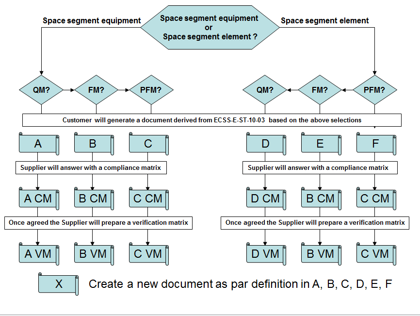 Figure: Logic for customer tailoring and supplier answer through compliance and verification matrix
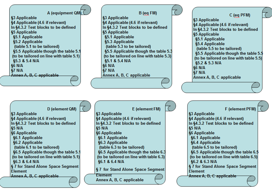 Figure: Clauses selection in First step of the tailoring
Verification guidelines
When preparing the verification close-out document (VCD) against the tailored standard derived from this standard (see D.2) it is not considered necessary to have a close-out for all requirements.
The Table D-1 identifies the need for verification close-out.
Table: Guideline for verification close-out
|
Clause
|
Verification close-out
|
Comment
|
|
4.1
|
No
|
(*)
|
|
4.2
|
No
|
(*)
|
|
4.3
|
No
|
(*)
|
|
4.4
|
Yes
|
|
|
4.5
|
No
|
(*)
|
|
4.6
|
No
|
(*)
|
|
5.1
|
No
|
(*)
|
|
5.2 Table 51
|
No
|
|
|
5.2 Table 52
|
Yes
|
|
|
5.3 Table 53
|
No
|
|
|
5.3 Table 54
|
Yes
|
|
|
5.4 Table 55
|
No
|
|
|
5.4 Table 56
|
Yes
|
|
|
5.5
|
Yes
|
|
|
6.1
|
No
|
(*)
|
|
6.2 Table 61
|
No
|
|
|
6.2 Table 62
|
Yes
|
|
|
6.3 Table 63
|
No
|
|
|
6.3 Table 64
|
Yes
|
|
|
6.4 Table 65
|
No
|
|
|
6.4 Table 66
|
Yes
|
|
|
6.5
|
Yes
|
|
|
7
|
No
|
(*)
|
|
Annex A, B, C
|
No
|
DRDs
|
|
(*) Verification is done when reviewing and agreeing on the test documentation.
| ||
Bibliography
|
ECSS-S-ST-00
|
ECSS system - Description, implementation and general requirements
|
|
ECSS-M-ST-10
|
Space project management - Project planning and implementation
|
|
ECSS-E-HB-10-02
|
Space engineering - Verification guidelines
|
|
ECSS-E-ST-31-02
|
Space engineering - Qualification of two-phase heat transport equipment
|
|
ECSS-E-HB-32-25
|
Space engineering - Mechanical shock design and verification handbook
|
|
EA-4/02, Dec 1999
|
Expression of the uncertainty of measurement in calibration
|
|
EA-4/16, Dec 2003
|
EA guidelines on the expression of uncertainty in quantitative testing
|