
Space product assurance
Materials, mechanical parts and processes
Foreword
This Standard is one of the series of ECSS Standards intended to be applied together for the management, engineering and product assurance in space projects and applications. ECSS is a cooperative effort of the European Space Agency, national space agencies and European industry associations for the purpose of developing and maintaining common standards. Requirements in this Standard are defined in terms of what shall be accomplished, rather than in terms of how to organize and perform the necessary work. This allows existing organizational structures and methods to be applied where they are effective, and for the structures and methods to evolve as necessary without rewriting the standards.
This Standard has been prepared by the ECSS-Q-ST-70C Rev.1 Working Group endorsed by the document and discipline focal point and approved by the ECSS Technical Authority.
Disclaimer
ECSS does not provide any warranty whatsoever, whether expressed, implied, or statutory, including, but not limited to, any warranty of merchantability or fitness for a particular purpose or any warranty that the contents of the item are error-free. In no respect shall ECSS incur any liability for any damages, including, but not limited to, direct, indirect, special, or consequential damages arising out of, resulting from, or in any way connected to the use of this Standard, whether or not based upon warranty, business agreement, tort, or otherwise; whether or not injury was sustained by persons or property or otherwise; and whether or not loss was sustained from, or arose out of, the results of, the item, or any services that may be provided by ECSS.
Published by: ESA Requirements and Standards Division
ESTEC, P.O. Box 299,
2200 AG Noordwijk
The Netherlands
Copyright: 2014© by the European Space Agency for the members of ECSS
Change log
|
ECSS-Q-70A19 April 1996
|
First issue
|
|
ECSS-Q-70B14 December 2004
|
Second issue
|
|
ECSS-Q-ST-70C
|
Third issue
|
|
ECSS-Q-ST-70C Rev.1
|
Third issue Revision 1
|
Scope
This Standard specifies the requirements and statements applicable to materials, mechanical parts and processes to satisfy the mission performance requirements.
This Standard also specifies the documentation requirements and the procedures relevant to obtaining approval for the use of materials, mechanical parts and processes in the fabrication of space systems and associated equipment.
This Standard covers the following:
management, including organization, reviews, acceptance status and documentation control;
selection criteria and rules;
evaluation, validation and qualification, or verification testing;
procurement and receiving inspection;
utilization criteria and rules.
The relationship between activities and programme phases is defined in Annex E.
The provisions of this Standard apply to all actors involved at all levels in the production of space systems. These can include manned and unmanned spacecraft, launchers, satellites, payloads, experiments, electrical ground support equipment, mechanical ground support equipment, and their corresponding organizations.
This standard may be tailored for the specific characteristics and constraints of a space project in conformance with ECSS-S-ST-00.
Normative references
The following normative documents contain provisions which, through reference in this text, constitute provisions of this ECSS Standard. For dated references, subsequent amendments to, or revisions of any of these publications do not apply. However, parties to agreements based on this ECSS Standard are encouraged to investigate the possibility of applying the most recent editions of the normative documents indicated below. For undated references the latest edition of the publication referred to applies.
|
ECSS-S-ST-00-01
|
ECSS system - Glossary of terms
|
|
ECSS-E-ST-20-06
|
Space engineering - Spacecraft charging
|
|
ECSS-M-ST-80
|
Space product assurance - Risk management
|
|
ECSS-Q-ST-10
|
Space product assurance - Product assurance management
|
|
ECSS-Q-ST-10-04
|
Space product assurance - Critical-item control
|
|
ECSS-Q-ST-10-09
|
Space product assurance - Nonconformance control system
|
|
ECSS-Q-ST-20
|
Space product assurance - Quality assurance
|
|
ECSS-Q-ST-40
|
Space product assurance - Safety
|
|
ECSS-Q-ST-70-01
|
Space product assurance - Cleanliness and contamination and control
|
|
ECSS-Q-ST-70-02
|
Space product assurance - Thermal vacuum outgassing test for the screening of space materials
|
|
ECSS-Q-ST-70-04
|
Space product assurance - Thermal testing for the evaluation of space materials, processes, mechanical parts and assemblies
|
|
ECSS-Q-ST-70-06
|
Space product assurance - Particle and UV radiation testing of space materials
|
|
ECSS-Q-ST-70-09
|
Space product assurance - Measurements of thermo-optical properties of thermal control materials
|
|
ECSS-Q-ST-70-21
|
Space product assurance - Flammability testing for the screening of space materials
|
|
ECSS-Q-ST-70-22
|
Space product assurance - Control of limited shelflife materials
|
|
ECSS-Q-ST-70-29
|
Space product assurance - Determination of offgassing products from materials and assembled articles to be used in a manned space vehicle crew compartment
|
|
ECSS-Q-ST-70-36
|
Space product assurance - Material selection for controlling stresscorrosion cracking
|
|
ECSS-Q-ST-70-37
|
Space product assurance - Determination of the susceptibility of metals to stresscorrosion cracking
|
|
ECSS-Q-ST-70-71
|
Space product assurance - Materials, processes and their data selection
|
Terms, definitions and abbreviated terms
Terms from other standards
For the purpose of this Standard, the terms and definitions from ECSS-S-ST-00-01 apply, in particular for the following terms:
material
Terms specific to the present standard
critical mechanical part
mechanical part that requires specific attention or control due to fracture mechanics aspects and limitedlife aspects, or with which the supplier has no previous experience of using the mechanical part in the specific application and environment or that are new or nonqualified, or that has caused problems during previous use that remain unresolved
critical process
process new to an individual company or nonverified for the application in question or has caused problems during previous use that remain unresolved
critical material
material that is new to an individual company or nonvalidated for the particular application and environment, or that has caused problems during previous use that remain unresolved
mechanical part
piece of hardware which is not electrical, electronic or electromechanical, and which performs a simple elementary function or part of a function in such a way that it can be evaluated as a whole against expected requirements of performance and cannot be disassembled without destroying this capability
process
set of interrelated resources and activities which transforms a material or semifinished product into a semifinished product or final product
request for approval (RFA)
document with which the supplier or user asks the competent body for permission to use a critical material, part or process
special process
process where quality cannot be completely ensured by visual inspection of the end article only
Abbreviated terms
For the purpose of this Standard, the abbreviated terms from ECSS-S-ST-00-01 and the following apply:
|
Abbreviation
|
Meaning
|
|
AA
|
Aluminium Association
|
|
AOCS
|
attitude and orbit control system
|
|
ATOX
|
atomic oxygen
|
|
AISI
|
American Iron and Steel Institute
|
|
CDA
|
Copper Development Association
|
|
CDR
|
critical design review
|
|
CFRP
|
carbon fibre reinforced polymer
|
|
CI
|
configuration item number (as per project definition)
|
|
DML
|
declared material list
|
|
DMPL
|
declared mechanical part list
|
|
DPL
|
declared process list
|
|
DRD
|
document requirements definition
|
|
EEE
|
electrical, electronic and electromechanical
|
|
ESA
|
European Space Agency
|
|
ESMDB
|
European Space Materials Database
|
|
GOX
|
gaseous oxygen
|
|
GSE
|
ground support equipment
|
|
LEO
|
low Earth orbit
|
|
LOX
|
liquid oxygen
|
|
MIP
|
mandatory inspection point
|
|
MMPP
|
Materials, mechanical parts and processes
|
|
MMPDS
|
Metallic Materials Properties Development and Standardisation
|
|
MPCB
|
Material, Mechanical Parts and Processes Control Board
|
|
NASA
|
National Aeronautics and Space Administration
|
|
NCR
|
nonconformance report
|
|
NRB
|
nonconformance review board
|
|
PA
|
product assurance
|
|
PDR
|
preliminary design review
|
|
PID
|
process identification document
|
|
PMP
|
parts, materials, processes
|
|
QR
|
qualification review
|
|
QRR
|
qualification review report
|
|
RFA
|
request for approval
|
|
RFD
|
request for deviation
|
|
SCC
|
stresscorrosion cracking
|
Nomenclature
The following nomenclature applies throughout this document:
The word “shall” is used in this Standard to express requirements. All the requirements are expressed with the word “shall”.
The word “should” is used in this Standard to express recommendations. All the recommendations are expressed with the word “should”.
It is expected that, during tailoring, recommendations in this document are either converted into requirements or tailored out.
The words “may” and “need not” are used in this Standard to express positive and negative permissions, respectively. All the positive permissions are expressed with the word “may”. All the negative permissions are expressed with the words “need not”.
The word “can” is used in this Standard to express capabilities or possibilities, and therefore, if not accompanied by one of the previous words, it implies descriptive text.
In ECSS “may” and “can” have completely different meanings: “may” is normative (permission), and “can” is descriptive.
The present and past tenses are used in this Standard to express statements of fact, and therefore they imply descriptive text.
General requirements
MMPP management requirements
Overview
The general MMPP activity within the framework of a project is summarized in Figure 41.
MMPP plan
The supplier shall prepare, maintain and implement a MMPP plan, as part of the overall PA plan in conformance with DRD from Annex A of ECSS-Q-ST-10 and this Standard or as a separate document.
The MMPP plan shall be submitted to the customer for approval.
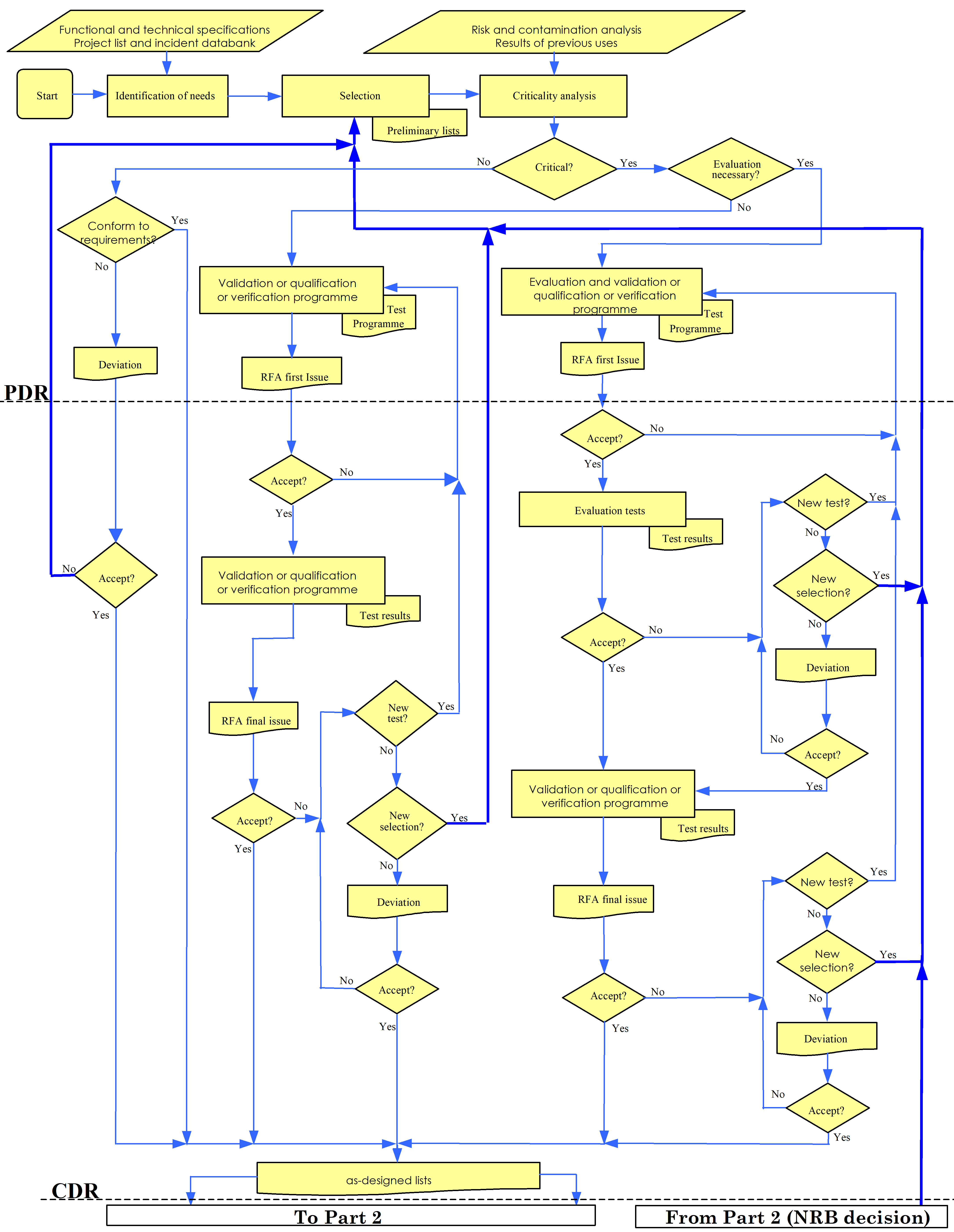 Figure 41: Materials, mechanical parts and processes flow chart
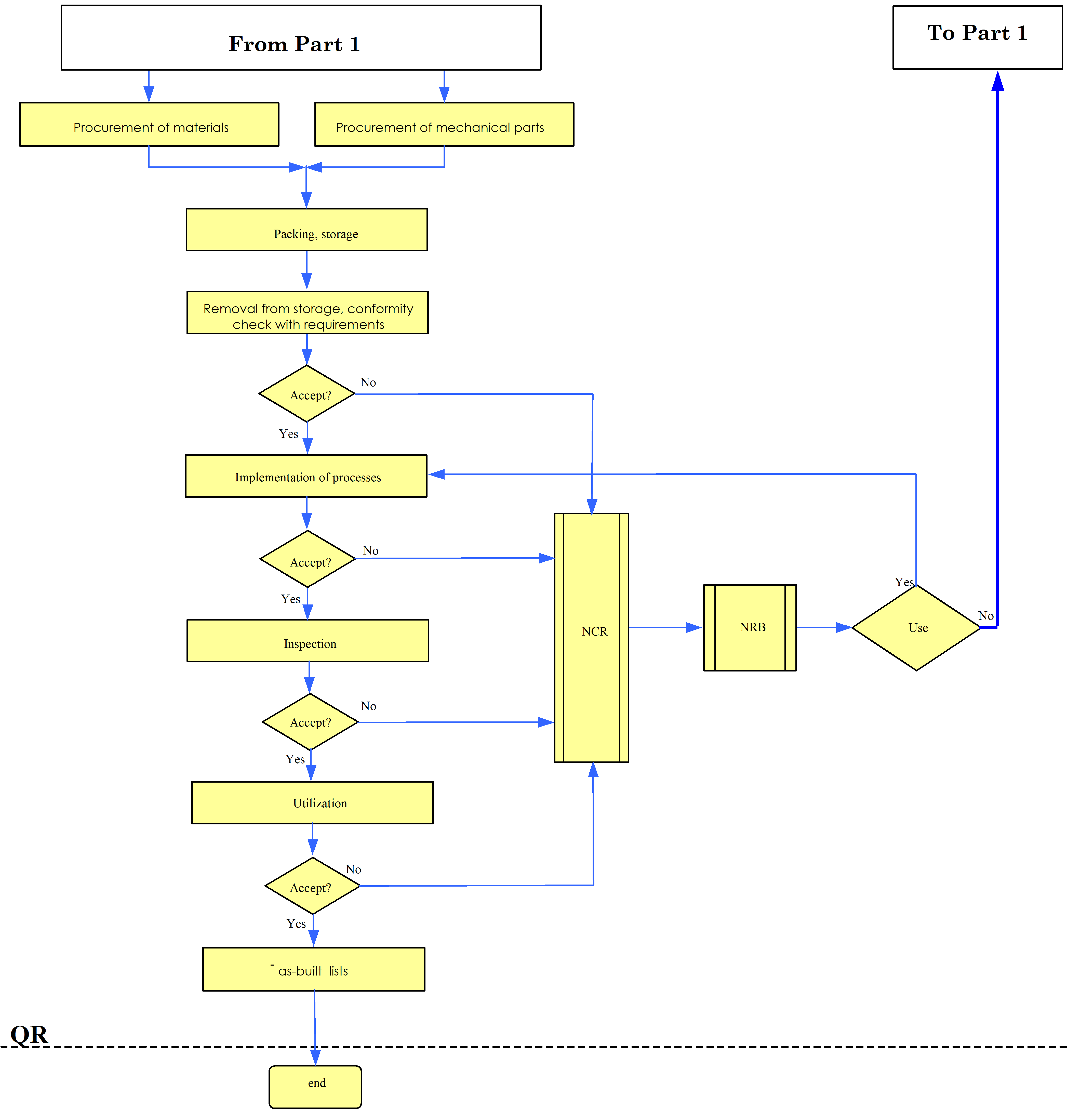 Figure 41: Materials, mechanical parts and processes flow chart (continued)
Table 41: Steps to be taken to get approval for materials, mechanical parts and processes (MMPP)
|
Phase
|
Materials
|
Mechanical parts
|
Processes
| |||
|
Step
|
Comments
|
Step
|
Comments
|
Step
|
Comments
| |
|
Critical Analysis
|
1
|
|
1
|
|
1
|
|
|
Evaluation (usually by test methods defined by ECSS standards)
|
2
|
Critical materials are tested, e.g. outgassing, SCC, flammability.
|
2
|
Mechanical parts are tested by, for example, vibration, thermal analysis, offgassing and life test.
|
2
|
Critical processes are evaluated by testing “technology samples” including all, for example, electrical interconnection processes and painting, adhesive bonding, welding.
|
|
Verification
|
Not applicable
|
Not applicable
|
3
|
Verification tests usually defined in ECSS standards
| ||
|
Validation
|
3
|
|
Not applicable
|
Not applicable
| ||
|
Qualification
|
Not applicable
|
3
|
|
Not applicable
| ||
|
Approval
|
|
By RFA (Annex D) or DML
|
|
By RFA (Annex D) or DMPL/DPL
|
|
By RFA (Annex D) or DPL
|
|
NOTE 1 Project approval is always by means of the request for approval (RFA) form and the projects’ declared materials list (DML), declared mechanical parts list (DMPL) and declared processes list (DPL).
| ||||||
MMPP Manager and MPCB
<< deleted >>
<< deleted >>
The supplier shall appoint a MMPP manager.
The MMPP Manager shall ensure that the Materials, Mechanical Parts and Processes used to manufacture a spacecraft or a launcher satisfy both the ground and flight functional requirements and constraints of the project.
To obtain the validation status for materials and qualification status for parts and verification status for processes, the MMPP manager shall present to the customer activities which were performed in conformance with requirement 4.1.3d together with the results obtained.
The MMPP manager shall organize Materials, Mechanical Parts and Processes Control Board (MPCB) at all suppliers with the task to review and approve the Materials, Mechanical Parts and Processes as specified in the Clauses 5, 6, and 7.
The MPCB activity shall start not later than at PDR.
The MMPP Manager shall agree with the customer on the MPCB’s activities at PDR.
Minimum tasks of the MPCB shall be as follows:
- Coordination of the initiation and approval of RFA’s in conformance with DRD from the Annex D by involving the relevant technical discipline.
- Review and approval of test programme and related results.
- Review of preliminary Declared Materials, Mechanical Parts and Processes Lists and of any available evidence to support the approval, by the PDR.
- Review and approval of Declared Materials, Mechanical Parts and Processes Lists and of the evidence for the approval by the CDR.
- Review and approval of any change to the approved Declared Materials, Mechanical Parts and Processes Lists.
Management and consolidation of the activities
Overview
The relationship between materials and processes activities and programme phases is shown in Annex E.
Establishing and processing of lists
Each supplier and subsupplier shall establish, collect, review and deliver the declared materials, mechanical parts and processes lists including all the items intended for use in the flight equipment.
The lists specified in 4.2.2a shall reflect the current design at the time of issue.
The lists specified in 4.2.2a shall contain the materials, mechanical parts and processes used in the current design to:
- demonstrate compliance with all requirements of the programme;
- verify the results of equipment supplier activities;
- control and monitor the status of materials, mechanical parts and processes in conformance with programme milestones.
See Annex F.
The following constraints should apply:
- maximum use of the materials and processes specified in approved data sources and items already approved on similar projects;
- use of project related preferred lists, if available.
For approved data sources see example of ESMDB database in the Annex A of the ECSS-Q-ST-70-71.
The following constraints shall be assessed:
- requirements originating from the initial technical specification.
- programmatic project requirements and conditions. An analysis of the criticality of preliminary lists specified in the 4.2.2a shall be performed such that, after checking the conformity of the materials, mechanical parts and processes, against all the project requirements, allows them to be classified into three categories:
- Critical items, subject to evaluation, validation, qualification, or verification programmes.
- Items that are not critical but which do not conform to one or more project requirements.
- Noncritical items.
For items classified as critical in conformance with 4.2.2f.1 a request for approval shall be submitted in conformance with Annex D.
For items classified as not critical but which are not in conformance with one or more project requirements in accordance with 4.2.2f.2 a justified deviation request should be drafted.
Management of the lists
The supplier shall document all materials in the Declared materials list in conformance with Annex A.
The supplier shall document all mechanical parts in the Declared mechanical parts list in conformance with Annex B.
The supplier shall document all processes in the Declared process list in conformance with Annex C.
The supplier shall process the lists of lower level suppliers to ensure exchangeabililty, traceability searchability, sortability, storability and retrievability for that set of lists, before submitting it to the customer.
The lists specified in the requirement 4.2.3a, 4.2.3b and 4.2.3c shall be updated during the course of the project.
The preliminary lists specified in the requirement 4.2.3a, 4.2.3b and 4.2.3c shall include the items from suppliers’ preliminary needs.
They are used to identify critical items (available for the PDR).
The asdesigned lists shall include the items from the baselines various design files, available for CDR.
Any change after CDR or QR shall be reflected in the list and shall be in accordance with Figure 41 (Part 2).
- 1 The MMPP manager is responsible within the programme to ensure that all the information needed is given and that the approval status is consistent with technical and scheduling objectives and data is exchangeable.
- 2 Where no project requirements exist for a separate DMPL, the mechanical parts can be entered into a separate section of the DML.
- 3 The materials of, for example, screws and nuts that are made up of a few materials can be listed in the DMPL. The materials (metals and plastics) of complex parts can be listed in the DML with, for example, outgassing, toxicity, flammability, corrosion and stress corrosion values and reference to the DMPL item.
The supplier shall establish, collect, review and deliver the declared materials, mechanical parts and processes lists in an electronic format in conformance with Annex A, Annex B, and Annex C.
The supplier shall demonstrate that the lists specified in the requirements 4.2.3a, 4.2.3b and 4.2.3c have been formally approved prior to their delivery to the customer.
Supplier role and responsibilities
The supplier shall perform the following tasks:
- obtaining the correct and complete lists from lower level suppliers;
- providing provisional and, later, definitive approval for each list;
- submitting the project declared lists for approval prior to initiation of the hardware phase, before CDR.
The lists specified in the requirement 4.2.3i by the suppliers shall include all the information described in this Standard.
Amendments to the lists specified in the requirement 4.2.3 a, b and c shall be implemented through established change procedures.
The following documentation shall be delivered to the customer upon request: - RFA with reference and issue in conformance with DRD in Annex D;
- evaluation reports;
- deviation requests. The material, mechanical parts or process justification files shall be made available to the customer upon request either on the supplier site, or by any other process agreed by both parties.
For example, by non-disclosure agreement.
Technical constraints
Mechanical parts, and materials and processes shall satisfy the mission’s functional requirements and constraints.
Mechanical parts, and materials and processes shall satisfy both ground environment and flight requirements and constraints.
Examples are:
- Ground environment constraints: manufacture, tests, storage, maintenance, transport and integration
- Flight constraints: launch and orbit.
<< deleted >>
The estimated availability of the parts and products obtained from materials and processes used shall be compatible with the space system’s life cycle.
Examples of space system’s life cycle are tests, storage and mission.
Cleanliness and contamination control
The supplier shall establish and maintain a contamination and cleanliness control programme including, as a minimum:
- cleaning procedures, and
- cleanliness monitoring procedures or methods. The risks of chemical or particle pollution generated by parts, materials or processes used shall be identified and reduced as specified in ECSS-M-ST-80 clause 7.2, in conformance with mission requirements.
Cleanliness or contamination analysis is example of mission requirements.
For cleanliness or contaminationcritical applications, a chemical and particle requirement specification and a specific cleanliness control plan shall be established in conformance with DRDs from Annex A and Annex B of ECSS-Q-ST-70-01.
Safety hazardous mechanical parts and materials
Mechanical parts and materials with hazardous characteristics shall be identified, managed and processed in conformance with requirements from clause 5 to clause 8 of ECSS-Q-ST-40.
Optical, mechanical or electrical GSE hardware
When optical, mechanical or electrical GSE materials are used in thermal vacuum or interfacing with flight hardware, degradation shall be assessed.
For example, contamination, surface degradation, electromechanical and chemical effects.
Selection of space materials and processes
For the selection of space materials and processes, ECSS-Q-ST-70-71 shall be applied.
Materials control
Technical criteria for selection of materials
General
Material design data shall be generated for the intended service conditions using test and analysis procedures approved by the customer.
Material properties shall be compatible with the environments to which they are exposed during terrestrial testing prior to launch, and during the mission.
The requirements of clause 5 apply when the environmental conditions of the mission require their application. The specific requirements, test methods and acceptance or rejection criteria are presented in the ECSS-Q-ST-70 series of documents.
Temperature
Material properties shall be compatible with the thermal environment to which they are exposed.
Examples of thermal environment are also the passage through transition temperatures, e.g. phase transitions, ductile-brittle transition temperatures for metals, glass transition (Tg) for polymer materials, and environmental factors which affect these properties, such as moisture.
Thermal cycling and thermo optical
Materials subject to thermal cycling shall be assessed for their ability to withstand induced thermal stress.
The following materials shall be tested in conformance with requirements from clause 5 of ECSS-Q-ST-70-04:
- Materials susceptible to thermal vacuum effect.
- Materials of unknown characteristics in respect to thermal vacuum.
For a non-exhaustive list of materials specified in the requirement 5.1.3b.1, see ECSS-Q-ST-70-04 Clause 1.
Materials subject to thermal cycling except the case specified in the requirement 5.1.3b, shall be tested in conformance with a procedure approved by the customer.
Thermo optical properties shall be evaluated in conformance with requirement from clause 4 of ECSS-Q-ST-70-09.
Directional effects due to manufacturing or processing shall be evaluated via dedicated testing to be agreed with the customer.
Vacuum
<< deleted >>
Outgassing screening tests shall be carried out in conformance with requirements from clause 5 of ECSS-Q-ST-70-02.
The screening process applied depends on the application
All organic materials for use in space systems shall be evaluated to determine their outgassing characteristics.
The need for retest outgassing characteristics of materials used for an extended period of time at a temperature higher than 50 C should be mutually agreed with the customer.
When dynamic outgassing tests are required see ECSS-Q-TM-70-52.
Offgassing and toxicity
Spacecraft and associated equipment shall be manufactured from materials and by processes that do not cause hazard to personnel or hardware, either on the ground or in space.
Requirements from clause 4 of ECSS-Q-ST-70-29 shall apply for the characterization of offgassing products.
MIL-HDBK-454 test method is not space relevant.
For materials for the use in manned compartments of a spacecraft or space segment elements, offgassing and toxicity analysis shall be performed.
The levels of offgassing and toxicity specified in the requirement 5.1.5c shall be agreed with the customer.
Flammability
The materials flammability resistance, shall be evaluated in conformance with requirements from the clause 5 of ECSS-Q-ST-70-21 for the most hazardous environment envisaged for their use, and be applicable to:
- unmanned spacecraft or space segment elements launched by a manned space transportation system when powered on launch, and
- manned spacecraft and space segment elements.
See also NASA STD-6001.
Radiation
Materials exposed to radiation shall be assessed in conformance with requirements from clause 5 of ECSS-Q-ST-70-06 to determine their resistance to the radiation dosage expected during the mission.
Evaluation of materials resistance to radiation shall include the combined effects of particle radiation and ultraviolet radiation in the normal space environment, along with any mission-specific radiation levels.
The effect of bleaching due to vacuum or air recovery shall be evaluated, in case ex-situ measurements are performed.
In case synergistic testing is not possible it shall be proven that synergistic effects caused by radiation and temperature are not degrading the materials properties.
In case technical limits prevent the synergistic testing approach, it shall be so justified, and the justification for sequential testing shall be provided.
For example when different acceleration factors are required for particle and UV radiation.
Electrical charge and discharge
External surfaces of the spacecraft shall be conductive, interconnected and grounded to the spacecraft structure to avoid the buildup of differential charges in conformance with requirements from clause 6 to clause 10 of ECSS-E-ST-20-06.
Corrosion
For all materials that come into contact with atmospheric gases, cleaning fluids or other chemicals, it shall be demonstrated that the degradation of properties during their anticipated servicelife does not prevent to meet the performance and integrity requirements.
All mechanical parts, assemblies and equipment, including spares, shall be finished to provide protection from corrosion.
This applies equally to fasteners and other fixing devices, such as insert systems.
Stresscorrosion
Materials used for structural and load bearing applications (i.e. subject to tensile stress) shall be selected in accordance with requirements of clauses 5.2.1, 5.2.3 and 5.2.4 of ECSS-Q-ST-70-36.
Any material not covered by cases specified in requirement 5.1.10a shall be tested in conformance with requirements from clause 5 of ECSS-Q-ST-70-37.
Fluid compatibility
Materials within the system exposed to reactive fluids, both directly and as a result of single point failures when failure propagation effects cause hazardous operation of interfacing hardware shall be compatible with that fluid in their application.
Example of reactive fluids are liquid oxygen (LOX) and gaseous oxygen (GOX).
<< deleted >>
The compatibility of materials which are or can come into contact with LOX or GOX shall be evaluated except the case specified in the requirement 5.1.11d.
See NASA-STD-6001 Tests No. 13 and No. 14.
In case no compatibility data are available, tests shall be performed for reactive fluids other than oxygen.
See NASA-STD-6001 Test No. 15.
Galvanic compatibility
When bimetallic contacts are used, the choice of the pair of metallic materials used shall be agreed with the customer.
This also includes metaltoconductive fibrereinforced materials contacts.
Galvanic compatibilities shall be selected in conformance with Table 51.
Materials not listed in Table 51 shall be evaluated in a flightsimulated configuration using an accelerated environment to be agreed by the customer.
Atomic oxygen
All materials for use on the external surfaces of spacecraft for use in Low Earth Orbit (LEO) altitudes, between 200 km and 700 km, shall be evaluated for their resistance to atomic oxygen (ATOX).
The flux level varies with altitude, velocity vector and solar activity. Fluence levels vary with the duration of exposure.
Test procedures shall be subject to the approval by the customer.
The effect of ATOX on thermo optical properties including specularity shall be evaluated.
Data related to ATOX are presented in ECSS-E-ST-10-04.
Micrometeoroids and debris
The effect of impacts by micrometeoroids and debris on materials shall be reviewed and assessed on a case by case basis.
Use of materials shall comply with safety evaluation and assessment results concerning design and application criteria or details.
Micrometeoroids and debris analysis and test procedures shall be subject to the approval by the customer.
Moisture absorption and desorption
Moisture absorption shall be prevented during manufacture and storage of hygroscopic materials.
Table 51 Compatible couples for bimetallic contacts
|
Pure metals and alloys in alphabetical order (including carbon) |
AluminiumCopper alloys |
Al (pure), AlZinc alloys |
Cadmium |
Cast iron (austenic) |
Chromium |
Copper, Brasses |
CuproNickel, Albronzes, Sibronzes |
Gold, Platinum, Carbon, Rhodium |
Gunmetal (CuZn10 alloy), Pbronzes, Snbronzes |
Magnesium |
Nickel, Monel, Inconel, Nickel/Molybdenumalloys |
Silver |
SnPb alloys (all), Tin, Lead |
Stainless steel 18/8 (300 series) |
Stainless steel 13Cr (400 series) |
Steel (carbon, low alloy), Cast iron |
Titanium and Tialloys |
Zinc, Beryllium |
|
|
AluminiumCopper alloys |
|
1 |
1 |
3 |
3 |
3 |
3 |
3 |
3 |
2 |
2 |
3 |
1 |
2 |
2 |
3 |
2 |
2 |
|
|
Al (pure) AlZinc alloys |
|
|
1 |
3 |
3 |
3 |
3 |
3 |
3 |
2 |
3 |
3 |
2 |
3 |
3 |
3 |
3 |
2 |
|
|
Cadmium |
|
|
|
2 |
2 |
2 |
2 |
2 |
2 |
1 |
2 |
2 |
0 |
1 |
1 |
2 |
2 |
2 |
|
|
Cast iron (austenic) |
|
|
|
|
1 |
1 |
1 |
2 |
1 |
3 |
1 |
2 |
1 |
1 |
1 |
2 |
1 |
3 |
|
|
Chromium |
|
|
|
|
|
1 |
0 |
0 |
1 |
3 |
1 |
0 |
2 |
0 |
0 |
2 |
0 |
3 |
|
|
Copper, Brasses |
|
|
|
|
|
|
0 |
2 |
0 |
3 |
1 |
1 |
2 |
1 |
1 |
3 |
0 |
3 |
|
|
CuproNickel Albronzes Sibronzes |
|
|
|
|
|
|
|
2 |
0 |
3 |
1 |
1 |
2 |
2 |
1 |
3 |
0 |
3 |
|
|
Gold Platinum, Carbon Rhodium |
|
|
|
|
|
|
|
|
2 |
3 |
2 |
0 |
3 |
0 |
1 |
3 |
0 |
3 |
|
|
Gunmetal(CuZn10 alloy) Pbronzes Snbronzes |
|
|
|
|
|
|
|
|
|
3 |
1 |
1 |
1 |
0 |
0 |
3 |
0 |
3 |
|
|
Magnesium |
|
|
|
|
|
|
|
|
|
|
3 |
3 |
2 |
3 |
3 |
3 |
3 |
3 |
|
|
Nickel Monel Inconel Nickel/Molybdenumalloys |
|
|
|
|
|
|
|
|
|
|
|
2 |
2 |
1 |
0 |
2 |
1 |
3 |
|
|
Silver |
|
|
|
|
|
|
|
|
|
|
|
|
3 |
0 |
0 |
3 |
0 |
3 |
|
|
SnPb alloys (all) Tin, Lead |
|
|
|
|
|
|
|
|
|
|
|
|
|
1 |
1 |
1 |
3 |
1 |
|
|
Stainless steel 18/8 (300 series) |
|
|
|
|
|
|
|
|
|
|
|
|
|
|
1 |
3 |
0 |
3 |
|
|
Stainless steel 13Cr (400 series) |
|
|
|
|
|
|
|
|
|
|
|
|
|
|
|
3 |
0 |
3 |
|
|
Steel (carbon, low alloy) Cast iron |
|
|
|
|
|
|
|
|
|
|
|
|
|
|
|
|
0 |
3 |
|
|
Titanium and Tialloys |
|
|
|
|
|
|
|
|
|
|
|
|
|
|
|
|
|
3 |
|
|
Zinc Beryllium |
|
|
|
|
|
|
|
|
|
|
|
|
|
|
|
|
|
|
|
|
Key:
| |||||||||||||||||||
Mechanical contact surface effects: cold welding, fretting, wear
For all solid surfaces in moving contact with other solid surfaces, it shall be demonstrated that the degradation of surface properties over the complete mission does not prevent to meet the performance requirements.
For all solid surfaces, moving or in static contact with other solid surfaces, and intended to be separated it shall be demonstrated that the increase in separation force during the physical contact does not exceed the specified limit.
Life
Materials shall be selected to ensure that they will meet the material performance requirements during all their specified lifetime. .
Bacterial and fungus growth
Materials selected for manned or fluid systems shall:
- not support bacterial or fungus growth,
- be sterilizable.
The extent of the degradation by the sterilization process shall be determined to define margins for design implementation.
The design and qualification of an equipment to be sterilised shall implement the defined margins for sterilisation degradation.
The level of bacterial growth and fungus contamination shall be determined on the assembled hardware.
Evaluation of organic materials used in the pressurized environment of long-term, manned spacecraft shall be performed prior to selection and verification.
Hydrogen embrittlement
The possibility of hydrogen embrittlement occurring during component manufacture or use shall be assessed.
The material evaluation specified in 5.1.19a shall be performed including the assessment of a protection and control.
Based on the assessment specified in the requirement 5.1.19a and 5.1.19b, protection and control measures shall be implemented to avoid hydrogen embrittlement during both mechanical parts manufacturing and use.
Hydrogen embrittlement can be introduced for example during e.g. plating, welding.
Mechanical parts subject to fatigue or sustained loading stresses, which are made of material susceptible to hydrogen embrittlement, shall be heat treated after coating.
Selection
General
Materials shall be chosen as follows:
- if an identical application in other space programmes similar with respect to environment constraints and lifetime to the proposed application exist, use materials used in such an application;
- otherwise:
- if materials exist for which satisfactory evaluation results are obtained on samples representative of the application with margin above the specified ones as regards conditions of use, use such materials;
- otherwise, use materials included in approved data sources.
For example: ESMDB (see Annex A of ECSS-Q-ST-70-71) ESA and NASA data banks.
Whether the materials are already validated or remain to be validated, their selection shall ensure that the following criteria are met:
- continuity of supply;
- reproducibility of characteristics;
- mechanical properties of materials processed according to a specified technique;
- environmental-stability properties under space conditions, together with mission- or application-specific requirements. Each critical material shall be validated for the specific application.
Critical material includes the ones of approved data sources.
Space-proven materials with heritage covering the specific mission requirements shall be selected at the earliest design stage.
The supplier shall be responsible for the selection of materials that are capable of meeting the requirements of his business agreement.
The supplier shall be responsible for storing and maintain all materials data in an internal database.
The access to the data, specified in requirement 5.2.1f, shall be granted to the customer.
To achieve high reliability and good performance, the use of a material shall be restricted to within its maximum qualified range of physical and mechanical properties.
All test methods and inspection techniques used to verify material characteristics and final products shall conform to standards approved by the customer.
All test methods and inspection techniques specified in the requirement 5.2.1i shall not be used before approval by the customer.
Constraints
Pure tin finish with more than 97 % purity shall not be used.
This is due to the possibility of whisker growth and transformation to grey tin powder at low temperatures.
The incoming inspection of each EEE component batch shall include the verification of the termination composition to avoid assembly of pure tin finish.
Cadmium and Zinc shall not be used as raw material or surface treatment for flight hardware.
Cadmium and Zinc shall not be used for ground support equipment exposed to vacuum or when in contact with the flight hardware.
For example during thermal vacuum testing phases on ground.
The incoming inspection of each non-EEE component batch shall include the verification of the metallic surface treatment to avoid assembly of pure tin, cadmium or zinc finish.
The materials presented in the following shall not be used:
- Beryllium oxide
- Mercury and its compounds
- Polyvinyl chloride (PVC)
- Radioactive material
This list is not exhaustive.
Beryllium shall not be used for structures.
Beryllium shall not be used in applications other than structures, unless:
- approved by the customer , and
- all safety requirements are implemented by the supplier.
Declared materials list (DML)
The supplier shall establish and maintain a declared materials list in conformance with Annex A.
Criticality analysis
Overview
To conform to mission requirements, the objective of the analysis is to identify whether further data are required.
Requirements
The supplier shall analyse all the materials contained in his preliminary lists with respect to criticality and in correlation with the risk analysis performed.
Any material not meeting the project requirements shall be subject to a RFD for customer approval.
Any critical material shall be subject to a RFA in conformance with Annex D to be submitted to the customer.
<< deleted >>
Evaluation and validation phases
General
If so identified by the criticality analysis, the supplier shall perform an evaluation phase before the validation phase for all critical materials with unknown characteristics (new materials) or with major changes in the use or in the configuration
In case of an extension of an existing application, the evaluation specified in requirement 5.5.1a need not be performed if so agreed with the customer.
Guarantied characteristics of materials and material supplier inspection methods, together with associated documents, shall be available for review at the supplier’s premises before the start of evaluation or qualification phases.
Evaluation phase
The evaluation specified in 5.5.1a shall assess as a minimum the following:
- the limits of use;
- the materials physical, chemical or functional characteristics along with their values and tolerances;
- behavioural tendencies and degradation processes depending on environmental parameters including sensitivity to pollution;
- acceptance criteria. When evaluation is performed, the supplier shall provide:
- an evaluation programme at PDR, according to Figure 41, and
- an evaluation report before CDR, according to Figure 41 and Table 41.
Validation phase
For all critical materials, a validation programme, available at PDR, shall be drawn up by the supplier and then implemented to check or confirm that the materials satisfy the mission requirements with the specified margins to obtain validation status.
Validation status shall be decided at CDR in view of the available results obtained written in validation report, and the review of corresponding documentation.
The validation programme and report shall be approved by the customer.
Approval phase
The material shall not receive an approval identification in the declared material list for the project unless the requirements specified in the clauses 5.5.2 and 5.5.3 are satisfied.
If approval is not granted, the supplier in charge of the item shall either:
- select another material, or
- propose a modified evaluation programme and resubmit for approval, or
- if actions specified in the requirements 5.5.4b.1 and 5.5.4b.2 fail to achieve positive results, initiate a deviation procedure.
Deviation request
For materials not conforming to project requirements, whether at the end of criticality analysis or of evaluation and validation tests, the supplier shall submit a request for deviation in conformance with requirements from the clause 5.2.3.5 of ECSS-Q-ST-10-09.
Procurement of materials
Procurement specifications
All materials shall be procured to an internationally or nationally specification approved by the supplier quality system, or an inhouse fully configured procurement specification which defines the materials properties, the materials requirements, the test methods, the acceptance criteria for the specific applications, source inspection (if any) and material supplier inspection.
Where material suppliers do not accept specifications and procurement is by means of a datasheet the supplier shall introduce internal, inhouse receipt inspection to ensure that the validation status of the material is maintained during the subsequent procurements.
Materials with long lead times or long procurement delays, versus the project schedule, shall be identified before the formal subsystem PDR.
Procurement shall be planned, documented and implemented to obtain reliable product assurance provision at CDR.
Backup plans shall be prepared and initiated whenever there is evidence of delays or technical problems.
The material requirements shall be accepted by the material supplier or manufacturer.
Incoming inspection procedure
All materials shall be submitted to an incoming inspection.
An incoming inspection procedure shall define the inspections and tests to be carried out, particularly for materials that are known to be variable in their final properties.
Use of materials
Validation status of materials
The supplier shall verify that all critical materials are validated before being used in the manufacture of qualification or flight products.
Any modification, change of condition or configuration of application shall lead to a re-evaluation in conformance with the process shown in Figure 41.
Traceability of materials
The supplier shall apply the traceability rules specified in the requirements from clause 5.2.5 of ECSS-Q-ST-20 to all materials.
Materials shall be identified by a unique reference number, code or a lot number to provide traceability.
The traceability allow to reconstruct the materials history, either individually (individual traceability) or by the manufacturing lot of which it was a part (lot traceability) in case of an incident or nonconformance, or a need for a technical investigation following failure or damage.
Packaging, storage, removal from storage
The supplier shall define provisions for packaging, storage and removal from storage for materials.
Measurements and inspections used to guarantee the material integrity and monitoring during storage and removal from storage shall be identified.
Limitedlife materials before implementation
The supplier shall ensure that all materials which have limitedlife characteristics have their date of manufacture or date of delivery and shelflife expiry date identified and clearly marked on each lot or batch.
Materials which have exceeded their shelflife expiry date shall not be recertified until the physical and chemical characteristics are inspected and the parameters, subject to deterioration, are evaluated for continued acceptability according to the acceptance and rejection criteria in conformance with requirements from the clause 4 of ECSS-Q-ST-70-22.
Limitedlife materials after implementation
Materials with limitedlife after implementation shall be identified and controlled in conformance with requirements from the clause 5 of ECSS-Q-ST-10-04.
- 1 Propellant is an example of material with limited-life after implementation
- 2 Storage and mission life are criteria for the assessment and control of those materials.
Materials nonconformances and alerts
Nonconformances and alerts shall be managed in conformance with requirements from the clause 5 and clause 6 of ECSS-Q-ST-10-09 and clause 5.2 of ECSS-Q-ST-10.
Health and safety
Material safety data sheet or equivalent shall be available for all materials.
Mechanical parts control
Selection of mechanical parts
The supplier shall verify that all materials and processes used in the manufacture of mechanical parts satisfy the mission technical requirements.
Selection
Mechanical parts shall be chosen from used for an identical application in other space programmes similar with respect to environment constraints and lifetime.
Type reduction actions shall be implemented at all levels of the programme.
Whether the mechanical parts are already qualified or remain to be qualified, their selection shall ensure that the following criteria are met:
- durability of supply;
- reproducibility of characteristics.
The supplier shall be responsible for storing and maintain all mechanical parts data in an internal database.
The access to the data, specified in requirement 6.2d, shall be granted to the customer.
Declared mechanical parts list (DMPL)
The supplier shall establish and maintain a declared mechanical parts list in conformance with Annex B.
Criticality analysis
Overview
To conform to mission requirements, the objective of the analysis is to identify whether further data are required.
Requirements
The supplier shall analyse all the mechanical parts contained in their preliminary lists with respect to criticality and in correlation with the risk analyses performed in conformance with requirements from the clause 5 of ECSS-Q-ST-10-04.
Critical parts shall be identified in the DMPL and included in the critical items list.
Any critical part shall be the subject of a RFA in conformance with Annex D submitted to customer approval.
Evaluation and qualification phases
General
If so identified by the criticality analysis, the supplier shall perform an evaluation phase before the qualification phase for all critical parts with unknown characteristics or with major changes in the use or in the configuration.
In case of an extension of an existing application, the evaluation indicated in 6.5.1a need not be performed if so agreed with the customer.
Guarantied characteristics of materials and material supplier inspection methods, together with associated documents, shall be available for review at the suppliers premises before the start of evaluation or qualification phases.
Refer to Table 41 for an explanation of the steps involved.
Evaluation phase
The evaluation specified in 6.5.1a shall include the following, as a minimum, for each critical part:
- the limits of use,
- the part’s physical or functional characteristics, along with its values and tolerances,
- behavioural tendencies and degradation processes depending on environment parameters, including sensitivity to pollution, and
- acceptance criteria. When an evaluation is performed the supplier shall provide:
- an evaluation programme at PDR, and
- an evaluation report before CDR. The behaviour of the parameters to be monitored which were also recorded during the evaluation programme tests, shall serve as a reference for the analysis of qualification test results.
Example of such behaviour is variation and change over time.
Qualification phase
For each critical part a qualification programme shall be drawn up by the supplier of the equipment using the critical part and then implemented to check or confirm whether the parts satisfy mission requirements with the specified margins.
Qualification status shall be decided at CDR in view of the available results obtained, written in qualification report, and the reviews of corresponding documentation .
The qualification programme and report shall be submitted to the customer for approval.
Approval phase
The mechanical parts shall not receive an approval identification in the declared mechanical parts list for the project unless the requirements from clauses 6.5.2 and 6.5.3 are satisfied.
If approval is not granted, the supplier in charge of the item shall either:
- select another mechanical part, or
- propose a modified evaluation programme and resubmit for approval, or
- if actions specified in the requirements 6.5.4b.1 and 6.5.4b.2 fail to achieve positive results, initiate a deviation procedure.
Deviation request
For mechanical parts not conforming to project requirements, whether at the end of criticality analysis or of evaluation and qualification tests, the supplier shall submit a request for deviation in conformance with requirements from the clause 5.2.3.5 of ECSS-Q-ST-10-09.
Procurement of mechanical parts
General
Mechanical parts with long lead times or procurement delays, versus the project schedule, shall be identified before the subsystem PDR.
Procurement shall be planned, documented and implemented to obtain reliable product assurance provision at CDR.
Backup plans shall be prepared and initiated whenever there is evidence of possible delays or technical problems.
Procurement specification
Each part shall be covered by a procurement specification or a standard approved by the supplier quality system.
The procurement specifications shall define the part characteristics, requirements, tests methods, acceptance criteria, lot acceptance testing, source inspection and material supplier inspection.
The procurement specifications shall be explicitly accepted by the mechanical part supplier or manufacturer.
Source inspection
For complex mechanical parts related to a specific project development, each supplier shall define the nature and frequency of their own source inspection points.
Source inspection shall be carried out by the customer on the premises of the supplier, mechanical part manufacturer, in conformance with requirements from the clauses 5.4.3 and 5.4.4 of ECSS-Q-ST-20.
Incoming inspection procedure
Each part or batch of mechanical parts shall be submitted to an incoming inspection.
An incoming inspection procedure shall be established defining the inspections and tests to be carried out.
Use of mechanical parts
Qualification status of mechanical parts
The supplier shall ensure that all critical parts are qualified before being used in the manufacture of qualification or flight products.
Any modification, change in condition or configuration of application shall lead to a re-evaluation in conformance with the process shown in Figure 41.
Traceability of mechanical parts
The supplier shall apply the traceability rules specified in clause 5.2.5 of ECSS-Q-ST-20 to his mechanical parts.
Parts shall be identified by a unique reference number or code and a lot number to provide traceability - where there is an incident or nonconformance, or for the purposes of technical investigations following failure or damage - to reconstruct the mechanical parts history, either individually (individual traceability) or by the manufacturing lot it was part of (lot traceability).
Packaging, storage, removal from storage
The supplier shall define provisions for packaging, storage and removal from storage for mechanical parts.
Measurements and inspections used to guarantee the part integrity and monitoring during storage and removal from storage shall be identified.
Limitedlife mechanical parts or parts subject to wearout
Limitedlife mechanical parts after implementation or subject to wear out shall be identified and controlled, including storage and mission life.
Examples of such mechanical parts are mechanisms, pyro initiators and Orings.
Limitedlife mechanical parts shall be assessed as candidates to the critical items list in conformance with requirements from clause 5 of ECSS-Q-ST-10-04.
Mechanical parts nonconformances and alerts
Management of mechanical parts nonconformances and alerts shall be in conformance with requirements from clause 5 to clause 6 of ECSS-Q-ST-10-09 and clause 5.2 of ECSS-Q-ST-10.
Process control
Specifications or procedures
Each process to be used in the manufacturing or assembly of a product shall be identified by a specification or procedure.
Reference shall be made to accept and reject criteria.
<< deleted >>
<< deleted >>
Process selection and training
Processes shall be chosen from already verified processes according to the following order of preference and priority:
- processes covered by space agencies or other governmental organization certification for identical conditions of use;
- processes for which satisfactory evaluation and verification results are obtained on samples representative of the application with a sufficient margin as regards conditions of use;
- processes already used by the same supplier for other space programmes in the same conditions of use. Whether the processes are already verified or remain to be verified, their selection shall ensure that the following criteria are met:
- reliability;
- inspectability;
- reworkability of the process item;
- reproducibility.
The supplier shall store and maintain all processes data in an internal database.
The access to the data, from requirement 7.3c, shall be granted to the customer.
Processes using limited-life materials shall be in conformance with the requirements from clause 4 of ECSS-Q-ST-70-22.
Operators shall be trained for all processes.
Operators performing special processes shall be certified in conformance with the requirements of the relevant standard.
Inspectors shall be trained and certified for all processes.
Certification shall be reassessed at least every two years.
All training and certification shall only be performed at a school or by certified instructors in conformance with customer requirements.
Retraining and recertification of operators shall be applied in the event of a new process, modification to an existing process or a change of the equipment used.
Retraining and recertification of inspectors shall be applied in the event of a new inspection procedure, modification to an existing inspection procedure or a change of an existing one.
In the case of a process suspension for four months continuously, retraining and recertification shall be performed.
Standards relating to the occupational health of operators working with processes resulting in exposure to vapours, dust or debris shall be implemented and controlled.
Declared processes list (DPL)
The supplier shall establish and maintain a declared processes list in conformance with Annex C.
Criticality analysis
Overview
To conform to mission requirements, the objective of the analysis is to identify whether further data is required.
Requirements
The supplier shall analyse all the processes contained in their preliminary lists with respect to criticality and in correlation with the risk analyses performed.
Critical processes shall be identified in the DPL and included in the list of critical items.
Any critical process shall be the subject of an RFA in conformance with Annex D submitted to customer approval.
Special processes shall be identified and controlled.
Process control shall be ensured by means of procedures available for customer review.
Best practice is to implement a statistical process control.
<< deleted >>
Evaluation and verification phase
General
If so identified by the criticality analysis, the supplier shall perform an evaluation phase before the verification phase for all critical processes which are new or with major changes in the use or in the configuration.
In case of an extension of an existing application, the evaluation specified in requirement 7.6.1a need not be performed if so agreed with the customer.
For confidential processes, the supplier shall prove that the process has been verified.
- 1 For example, by presenting a verification certificate from space agencies or other governmental organization responsible to check the applicability of this verification.
- 2 Refer to Table 41 for an explanation of the steps involved.
Evaluation phase
The evaluation specified in 7.6.1a shall include the following as a minimum for each critical process:
- the limits of use,
- the values, determined by test samples or technology samples, of relevant parameters and their tolerances, and
- acceptance criteria. When an evaluation is performed, the supplier shall provide
- an evaluation plan at PDR, and
- an evaluation report before CDR.
Verification phase
For each critical process, the supplier shall implement a verification programme.
The verification programme shall be defined in conformance with ECSS-E-ST-10-02.
The supplier shall ensure that the processes satisfy the mission requirements and that the parameters needed for the product design are defined so as to obtain verification status.
Verification status shall be decided at CDR in view of the available results obtained, written in verification report, and the review of corresponding documentation.
The verification programme and report shall be approved by the customer.
Approval phase
A processes shall not receive an approval identification in the declared processes list unless requirements from clauses 7.6.2 and 7.6.3 are satisfied.
In case approval specified in the requirement 7.6.4a is not granted, the supplier in charge of the item shall either:
- select other processes, or
- propose a modified evaluation programme and resubmit for approval, or
- if actions specified in 7.6.4b.1 and 7.6.4b.2 fail to achieve positive results, initiate a deviation procedure.
Deviation request
For processes not conforming to project requirements, whether at the end of criticality analysis or of evaluation and verification tests, the supplier shall submit a request for deviation in conformance with requirements from clause 5.2.3.5 of ECSS-Q-ST-10-09.
Use of a process
Verification status of a process
The supplier shall confirm that all critical processes have been verified before being used in the manufacture of qualification or flight products.
Any modification, change of condition or configuration of application shall lead to a re-evaluation in conformance with the process.
See Figure 41.
Reverification of a process
When a process needs to be reverified, a request for approval (RFA) in conformance with DRD from Annex D shall be established and a reverification programme shall be implemented.
Any prolonged stoppage in manufacturing, any major change of the facilities or procedures or any transfer of production to another entity can invalidate partially or completely the initial verification of a process.
Implementation of a process
Before implementation of a process, the supplier shall ensure that personnel are trained in accordance with the training and certification programme specified in 7.3f, 7.3g and 7.3h and that environment, means and documentation are adequate.
This verification shall ensure that:
- manufacturing and quality control tools associated with the process are adequate, calibrated and properly maintained are used under environmental and cleanliness conditions, in conformance with requirements from clause 4.4,
- personnel is trained and certified in accordance with the training and certification programme specified in 7.3f, 7.3g and 7.3h, and
- the processes specifications, manufacturing and inspection procedures and workmanship standards including definition of manufacturing operations and acceptance criteria exist.
- 1 Photographically documented if possible for visual acceptance criteria at the appropriate work and inspection stations.
- 2 For planning of manufacturing, assembly and integration operation and inspection see ECSS-Q-ST-20.
Traceability of processes
Traceability of processes shall be ensured in conformance with requirements from clause 5.2.5 of ECSS-Q-ST-20.
Process nonconformances and alerts
Process nonconformances and alerts shall be processed in conformance with requirements from clause 5 to clause 6 of ECSS-Q-ST-10-09 and clause 5.2.9 of ECSS-Q-ST-10.
Mandatory inspection points (MIP)
MIPs shall be defined in conformance with requirements from clause 5.5.8 of ECSS-Q-ST-20.
Packaging, storage, removal from storage
The supplier shall define provisions for packaging, storage, and removal from storage for products or semifinished products before and after implementation of processes.
ANNEX(normative)Declared materials list (DML) - DRD
DRD identification
Requirement identification and source document
This DRD is called from ECSS-Q-ST-70, requirements 4.2.3a and 5.3a.
Purpose and objective
The purpose of the DML is to have a detailed record of all the materials used to produce the products of a project or programme.
The data in the DML make possible to assess whether the materials are suitable for a specific application, at the supplier and the customer levels (in the approval status column).
The DML is prepared for each “Configuration item” at the relevant stages (e.g. at the start, PDR, CDR and QR) as defined in the flow chart given in Figure 41.
The following documents are linked to the DML:
the declared process list (DPL);
request for approval (RFA) materials.
Expected response
Scope and content
Materials groups
The DML shall contain the following statements:
- “Materials are classified into 20 groups depending on their type or their main use, see Table A-1”.
- “Primers are classified in the group of their associated component.”
- “Where no project requirement exists for a separate DMPL, mechanical parts are entered on the DML as a separate group with the corresponding numbers.”
If new groups are created, for a given project, these shall have numbers over 21.
Table: Material group numbers
|
Group number
|
Description
|
|
1
|
Aluminium and aluminium alloys
|
|
2
|
Copper and copper alloys
|
|
3
|
Nickel and nickel alloys
|
|
4
|
Titanium and titanium alloys
|
|
5
|
Steels
|
|
6
|
Stainless steels
|
|
7
|
Filler metals: welding, brazing soldering
|
|
8
|
Miscellaneous metallic materials
|
|
9
|
Optical materials
|
|
10
|
Adhesives, coatings, varnishes
|
|
11
|
Adhesive tapes
|
|
12
|
Paints and inks
|
|
13
|
Lubricants
|
|
14
|
Potting compounds, sealants, foams
|
|
15
|
Reinforced plastics (including PCBs)
|
|
16
|
Rubbers and elastomers
|
|
17
|
Thermoplastics
|
|
18
|
Thermoset plastics (including PCBs)
|
|
19
|
Material aspects of wires and cables
|
|
20
|
Miscellaneous nonmetallic materials, e.g. ceramics
|
Contents of the DML
The DML shall include the information stated in Figure A-1, where the header information identifies the list as the declared materials list and includes the issue number and date of issue, as follows:
- Item number (applicable to equipment manufacturer level only)
- This consists of the material group identifier and the user code. It takes the form of:
<group number>.<identifier within the group>.<running number>.<user code>
- This consists of the material group identifier and the user code. It takes the form of:
For example: 11.5.1.KOF.
* Characteristics of the item number are:
The user, identified by an agreed user code for the project.One only per material type.Does not change during the life of the materials list (subitems are permitted when deemed necessary).* Commercial identification or standardized designation
* Enter the correct and standard designation, such as the trade name plus number.
* If no trade name exists, enter the manufacturer’s name plus number.
* For metal alloys, the Aluminium Association (AA) system is recommended for aluminium alloys, and the American Iron and Steel Institute (AISI) system for steel. For other metals or alloys, the main constituent is entered first except in the case of a traditional name.
For example: brass or bronze.
* For each material, as designated in A.2.1<2>a2(a) to(c), use a unique item number. If several lines are used for different applications or processing, add subitem numbers.
- Chemical nature and product type
- For metallic materials, add the condition as procured if applicable.
Examples of such conditions are rolled and heat treatment.
* Where a semifinished product is procured, give the relevant state.
Examples of such state are form, plate and sheet.
* Give the thickness of the material, that can be an important parameter.
Examples of chemical nature are: epoxy resin, polyurethane adhesive, Ti6Al4V.
- Procurement information
- Manufacturer or distributor: name of the manufacturer and name of the distributor if different.
- Procurement specification: provide reference to one of the following:
the procurement specification with issue, revision and datea national or international specification or standard, if this exists, and identifies the source of procurement (if relevant), with issue, revision and datedatasheets, in which case indication of issue or date is not applicable.* Processing parameters List here a summary of the process parameters applied by the user of the process.
E.g. mixture proportions, cure temperature, special cleaning agent, surface treatment, thermal treatment and temperature, and reference to specification number.
- Use and location
-
Use codes able to define the location of the material with respect to the:
subsystem;particular piece of equipment (box or item);use of the equipment, e.g. a structural element, thermal control, electrical insulation.:::note If the CI number is not included in the list header, then a suitable abbreviation of the relevant subsystem is included. ::: -
Include any restrictions that apply to the use of a particular material in the corresponding comment column.
-
- Environmental code The environmental code is defined using Table A-2.
Table: Environmental code
|
Radiation/UV/ATOX (R)a
|
Ambience (A)
|
Temperature (T)b,c
| |
|
G: Geostationary
|
S: Outside shadow
|
V: Vacuum
|
1: 0 K to 100 K
|
|
L: Low orbit
|
L: Outside light
|
H: Hermetic
|
2: 101 K to 200 K
|
|
B: Radiation belt
|
|
M: Manned
|
3: 201 K to 300 K
|
|
I: Interplanetary
|
|
E: Elevated pressure
|
…
|
|
P: Planetary
|
|
|
|
|
a For all materials, a letter is selected from the lefthand column. For materials on the surface of the spacecraft, the letter “L” or “S” is added.
| |||
|
NOTE: The materials that are at a boundary between environments are described by two sets of codes.
| |||
- Size code The size code is indicated by an alphanumeric combination, such as A5, V2 or M3, as in Table A-3.
Table: Size code
|
Size code
|
Value
|
|
0
|
0 < A or V or M 1
|
|
1
|
1 < A or V or M 10
|
|
2
|
10 < A or V or M 100
|
|
3
|
100 < A or V or M 1 000
|
|
4
|
…
|
|
where: A is the area, in cm2
| |
- Validation references, justification for approval and prime comments and prime approval
- Make reference to relevant test data that demonstrates the acceptability of the material under the environmental conditions and the application relevant to the particular project concerned. Specifically, in column 9.1, corrosion (CORR), stress corrosion (SCC), flammability (FLAM), offgassing (OFFG) and outgassing (OUTG) data or reportreferences are entered.
- Use standard abbreviations to summarize the acceptance status of a material for a particular property.
- Use the justification for approval (column 9.2) and prime approval (column 9.3) columns for any additional information to obtain customer approval.
- Standard abbreviations are used to summarize the acceptability or otherwise of a material for a specific property. These are defined for the project.
- Select the supplier approval status code from Table A-4.
- Customer approval status code and comments
- Select this code from Table A-4.
- Include additional comments where appropriate.
If heritage is used as justification for approval it shall cover the current hardware configuration and mission profile.
Table: Approval status
|
Code
|
Description
|
|
A
|
Approved.
|
|
X
|
Approved with an RFA.
|
|
W
|
Approved with a concession.
|
|
P
|
Pending a decision.
|
|
O
|
Open.
|
|
R
|
Rejected.
|
|
D
|
Deleted.
|
|
NOTE If approval cannot be given and one of the other codes is entered, enter the comments in the appropriate column.
| |
Special remarks
The change record shall list the successive issues and their release dates since the first formal issue of the document.
The change record shall include a brief description of the updates which contributed to each issue or revision.
Figure A-1 of this DRD proposes an example of the format and defines the content within the framework of a project or a programme.
|
DECLARED MATERIALS LIST (DML) |
||||||||||||
|
Programme name: ABCDEFG |
CI no.: 12345676890 Group (Title): abcdefg |
Doc no.: 001 Issue/Revision: 1/4 |
Date: 01.10.2000 Page: 1 |
|||||||||
|
1
|
2
|
3
|
4
|
5
|
6
|
7
|
8
|
9
|
10
| |||
|
9.1
|
9.2
|
9.3
| ||||||||||
|
Item no. and user code |
Commercial identification or standardized designation |
1) Chemical nature 2) Product type |
1) Manufacturer/ supplier name 2) Procurement spec. Issue/RevDate |
Summary of process parameters |
1) Subsystem 2) Equipment 3) Use |
1) R 2) A 3) T |
1) A 2) V 3) M |
Acronym/ rating/ Validation Ref. for applicable properties |
1) Justification for approval 2) Prime comments |
Prime approval status |
Customer approval status/ comments |
|
|
1.2.1.TXES |
AZ5GU |
1) Al.Zn5.6 Mg2.5 Cdu1.6, Cr0.3 eq. AA7075 2) Plate |
1) Almet Pechiney 2) CRB 527 01/02/01.02.1996 |
T7351 and Iridit 14 heat treatment |
1) PL 2) E4 package 3) Structure |
1) LS 2) V 3) 3 |
1) 2) 3) M3 |
|
1) Used on ETS2 2) |
A |
Give evidence of ETS2 specific usage |
|
|
10.1.1.ETCA |
DC93500 |
1) Silicon 2) Two parts |
1) Dow Corning 2) E3846MC10S 02/02/1984 |
Mixture: 10/1 in g Curing: 4h/65 ºC |
1) PCU 2) Experiment tray 3) Part potting |
1) G 2) V 3) 3-4 |
1) 2) 3) M3 |
|
1) ECSSQ-ST-7001 2) |
A |
|
|
|
11.5.1.KOF |
ECCOFOAM EPH |
1) Polyurethane 2) Resin/Catalyst 1202H |
1) Emerson and Cuming 2) SP/FOK/05/684 03/01/25.06.1992 |
Resin/ Cat: 100/65g4h/40 C+48h/100 C |
1) GP 2) Platform 3) Package potting |
1) LS 2) M 3) 3-4 |
1) 2) V3 3) |
|
1) DU–96–352 2) Used at T > 100 C(Risk of distortion beyond) |
A |
A |
|
Figure: Example of a realized DML
ANNEX(normative)Declared mechanical parts list (DMPL) - DRD
DRD identification
Requirement identification and source document
This DRD is called from ECSS-Q-ST-70, requirements 4.2.3b and 6.3a.
Purpose and objective
The purpose of the DMPL is to have detailed record of all the mechanical parts used to produce the products of a project or programme.
The data in the DMPL make possible to assess whether the mechanical parts are suitable for a specific application, at the supplier and customer levels (in the approval status column).
The DMPL is prepared for each “Configuration item” at the relevant stages (e.g. Start, PDR, CDR and QRR) as defined in the flow chart given in Figure 41 of ECSS-Q-ST-70.
The following document is linked to the DMPL: request for approval (RFA) mechanical parts.
Expected response
Scope and content
Mechanical parts groups
The DMPL shall contain the following statements:
“Mechanical parts are classified into 11 groups depending on their type or their main use” (see Table B-1).
If, for a given project it is considered necessary to create new groups, these shall have numbers over 61.
Items that appear in the EEE parts list should not be repeated here.
For example, heaters, some valves, thermostats, relays, transformer coils and solenoids.
Table: Mechanical part group numbers
|
Group number
|
Description
|
|
51
|
Spacing parts (e.g. washers and spacers)
|
|
52
|
Connecting parts (e.g. bolts, nuts, rivets, inserts and clips)
|
|
53
|
Bearing parts (e.g. ballbearings and needle bearings)
|
|
54
|
Separating parts (e.g. pyrotechnics, springs and cutters)
|
|
55
|
Control parts (e.g. gears)
|
|
56
|
Fluid handling parts (e.g. diffusers)
|
|
57
|
Heating parts
|
|
58
|
Measuring instruments (e.g. gauges and thermocouples)
|
|
59
|
Optical passive equipment
|
|
60
|
Magnetic parts
|
|
61
|
Other parts
|
Contents of the DMPL
The DMPL shall include the information in Figure B-1, where the header information identifies the list as the declared mechanical parts list and includes the issue number and date of issue, as follows:
- Item number (applicable at equipment supplier level only)
- This consists of the mechanical part identifier and the user code. It takes the form of:
<group number>.<identifier within the group>.<running number>.<user code>
- This consists of the mechanical part identifier and the user code. It takes the form of:
For example: 7.2.1.ACSA.
* Characteristics of the item number are:
Identify the subcontractor by an agreed user code for the project.One only per mechanical part type. Does not change during the life of the mechanical parts list.* Commercial identification
* Enter the correct and standard designation, such as trade name plus number.
* If no trade name exists then enter the manufacturers’ name and number.
-
Type of part Describe the material and surface treatment (if applicable).
-
Procurement information
- Manufacturer or distributor: name of the manufacturer and name of the distributor if different.
- Procurement specification: provide reference to one of the following:
the procurement specification with issue, revision and datea national or international specification or standard, if this exists, and identifies the source of procurement (if relevant), with issue, revision and date.* Elementary function, main characteristics - Enter the function of the mechanical part.
- Enter the main characteristics of the mechanical part.
For example, number of revolutions per minute for a ball bearing.
-
Use and location Use codes able to define the location of the mechanical part with respect to the:
- subsystem;
- particular piece of equipment (box or item);
- use of the equipment.
-
Environmental code The environmental code is defined using Table B-2.
Table: Environmental code
|
Radiation/UV/ATOX (R)a
|
Ambience (A)
|
Temperature (T)b,c
| |
|
G: Geostationary
|
S: Outside shadow
|
V: Vacuum
|
1: 0 K to 100 K
|
|
L: Low orbit
|
L: Outside light
|
H: Hermetic
|
2: 101 K to 200 K
|
|
B: Radiation belt
|
|
M: Manned
|
3: 201 K to 300 K
|
|
I: Interplanetary
|
|
E: Elevated pressure
|
|
|
P: Planetary
|
|
|
|
|
a For all mechanical parts, a letter is selected from the lefthand column. For mechanical parts on the surface of the spacecraft, the letter “L” or “S” is added.
| |||
-
Criticality Enter “C” for critical or “N” for noncritical. If a mechanical part is considered critical, describe the reason for the criticality and methods of control.
-
Supplier reference, prime comments and prime approval status
- Use the supplier reference, prime comments and approval columns to enter all additional information that are necessary in order to obtain customer approval.
- This information comprises reference and issue of the RFA or approval, mechanical parts justification file, evaluation reports and deviation requests.
- Make reference to the relevant test data that demonstrates acceptability of the mechanical part under the environment conditions and the application relevant to the particular project concerned.
- Use standard abbreviations, defined by the customer, to summarize the acceptance status of a mechanical part for a particular property.
- In order to justify the use of a material for flammability resistance, list here the material thickness and height of oxygen share.
- Select the prime approval status code from Table B-3.
-
The customer approval status code and comments
- Select this code from Table B-3.
- Include additional comments where appropriate.
Table: Approval status
|
Code
|
Description
|
|
A
|
Approved
|
|
X
|
Approved with an RFA
|
|
W
|
Approved with a concession
|
|
P
|
Pending a decision
|
|
O
|
Open
|
|
R
|
Rejected.
|
|
D
|
Deleted
|
|
NOTE: If approval cannot be given and one of the other codes is entered, enter the comments in the appropriate column.
| |
Special remarks
The change record shall list the successive issues and their release dates since the first formal issue of the document.
This record shall include a brief description of the updates which contributed to each issue or revision.
Figure B-1 of this DRD proposes an example of the format and defines the content within the framework of a project or a programme.
|
DECLARED MECHANICAL PARTS LIST (DMPL) |
|||||||||||
|
Programme name: ABCDEFG
|
CI no.: 12345676890
|
Doc no.: 001
|
Date: 01.10.2000
| ||||||||
|
1
|
2
|
3
|
4
|
5
|
6
|
7
|
8
|
9
|
10
| ||
|
9.1
|
9.2
| ||||||||||
|
Item no. and user code |
Commercial identification |
Type of part |
1) Procurement specification 2) Issue/Revision/ Date |
1) Elementary function 2) Main characteristics |
1) Subsystem 2) Equipment 3) Use |
1) R 2) A 3) T |
1) Criticality 2) Reason and method of control |
1) Supplier Reference 2) prime comments |
Prime approval status |
Customer approval status/comments |
|
|
51.2.1.ACSA |
ESA003521000120 |
Copper/AL bimetal ring |
1) AIEV 2) From catalogue |
1) Separator ring 2) Heat conductor |
1) TC 2) Plate interface 3) Spacing and heat inspection |
1) G 2) V 3) 3-4 |
1) N 2) |
1) Used on all projects 2) |
A |
A |
|
|
52.2.1.ASAD |
A0090TX...XA |
Ti6Al4V screws > M4 |
1) White areo 2) ASNA0090 DSN2413 |
1) assembly 2) |
1) PTANK 2) plate 3) fixing |
1) G 2) V 3) 3-4 |
1) N 2) |
1) Used on TC2 2) |
A |
A |
|
|
60.1.1.ACSA |
42908TC/F |
Ferrite cores magnetic |
1) Magnetics, Data sheet 2) SP/MAGN/003 01.02/03.06.1999 |
1) Coil core of transformer 2) Magnetic component |
1) TC 2) South face 3) Heat regulation |
1) G 2) V 3) 3-4 |
1) C 2) to be qualified |
1) 2) |
|
|
|
Figure: Example of a realized DMPL
ANNEX(normative)Declared process list (DPL) - DRD
DRD identification
Requirement identification and source document
This DRD is called from ECSS-Q-ST-70, requirements 4.2.3c and 7.4a.
Purpose and objective
The purpose of the DPL is to have a detailed record of all the processes used to produce the products of a project or programme.
The data in the DPL make possible to assess whether the processes are suitable for a specific application, at the supplier and customer levels (in the approval status column).
The DPL is prepared for each “Configuration item” at the relevant stages (e.g. Start, PDR, CDR and QRR) as defined in the flow chart given in Figure 41 of ECSS-Q-ST-70.
The following documents are linked to the DPL:
declared material list (DPL),
request for approval (RFA) processes.
Expected response
Scope and content
Process groups
The DPL shall contain the following statements:
Processes are classified into 17 groups depending on their type or their main use, see Table C-1.
If, for a given project it is considered necessary to create new groups, these shall have numbers over 17.
Table: Process group numbers
|
Group number
|
Description
|
|
1
|
Adhesive bonding
|
|
2
|
Composite manufacture
|
|
3
|
Encapsulation/moulding
|
|
4
|
Painting/coating
|
|
5
|
Cleaning
|
|
6
|
Welding/brazing
|
|
7
|
Crimping/stripping/wire wrapping
|
|
8
|
Soldering
|
|
9
|
Surface treatments
|
|
10
|
Plating
|
|
11
|
Machining
|
|
12
|
Forming
|
|
13
|
Heat treatment
|
|
14
|
Special fabrication: processes developed specifically for the programme
|
|
15
|
Marking
|
|
16
|
Miscellaneous processes
|
|
17
|
Inspection procedures
|
Contents of the DPL
The DPL shall include the information in Figure C-1, where the header information identifies the list as the declared processes list and includes the issue number and date of issue, as follows
- Item number (applicable to equipment supplier level only)
- This consists of the process identifier and the user code. It takes the form of
<group number>.<identifier within the group>.<running number>.<user code>
- This consists of the process identifier and the user code. It takes the form of
For example: 1.2.1.SSEX
* Characteristics of the item number are:
Identify the subcontractor by an agreed user code for the project.One only per process type. Does not change during the life of the process list.* Process identification Indicate the correct and standard identification of the process, e.g. the process name or title: bonding, coating or soldering.
- Specification
- Identify the name or abbreviation of the process executor.
- Make a reference to the associated procedure, together with the issue, revision and date.
For example, national, international, EN, ISO, ECSS or company inhouse.
-
Process description Enter here a short description of the process.
-
Use and location Use codes able to define the location of the process with respect to the:
- subsystem,
- particular piece of equipment (box or item),
- use of the equipment.
For example, a structural element, thermal control, electrical insulation).
-
This column number is not used.
-
Associated item numbers Enter the associated material list (DML) or mechanical parts list (DMPL) with the process.
-
Criticality
- Enter “C” for critical or “N” for noncritical.
- If a process is considered to be critical, Enter the references to the relevant RFA.
-
Supplier reference, prime comments and approval
- Use the supplier reference and approval columns to enter all additional information that are necessary to obtain customer approval.
- Select the supplier approval status code from Table C-2.
- Give reference to qualification programme performed for critical processes.
-
The customer approval status code and comments
- Select this code from Table C-2.
- Include additional comments where appropriate.
If heritage is used as justification for approval it shall cover the current hardware configuration and mission profile.
Table: Approval status
|
Code
|
Description
|
|
A
|
Approved
|
|
X
|
Approved with an RFA
|
|
W
|
Approved with a concession
|
|
P
|
Pending a decision
|
|
O
|
Open
|
|
R
|
Rejected.
|
|
D
|
Deleted
|
|
If approval cannot be given and one of the other codes is entered, enter the comments in the appropriate column.
| |
Special remarks
The change record shall list the successive issues and their release dates since the first formal issue of the document.
This record shall include a brief description of the updates which contributed to each issue or revision.
Figure C-1 of this DRD proposes an example of the format and define the content within the framework of a project or a programme.
|
DECLARED PROCESS LIST (DPL) |
||||||||||
|
Programme name: ABCDEFG
|
CI no.: 1234567890
|
Doc no.: 001
|
Date: 14.05.2000
| |||||||
|
1
|
2
|
3
|
4
|
5
|
7
|
8
|
9
|
10
| ||
|
9.1
|
9.2
| |||||||||
|
Item no. and user code |
Process identification |
1) User name 2) Associated procedure issue/revision/ date |
Process description |
1) Subsystem code 2) Equipment code 3) Use |
Associated DML or DMPL item number |
1) Criticality 2) Reason for criticality |
1) Supplier Reference 2) Prime comments |
Prime approval status |
Customer approval status/ comments |
|
|
1.2.1.SSEX |
Bonding |
1) EREMS 2) E/SQ/PI/012 02/01/02.08.1984 |
Applying a spot of glue with a stainless steel dispenser |
1) BE3 2) C5 board 3) To fix parts |
6.1.2.ETC |
1) N 2) |
1) Used on ANTARES 2) |
A |
Give evidence of ANTARES specific usage |
|
|
4.3.1.KOF |
Coating |
1) CERCO 2) E/SQ/PI/023 02/01/08.12.1985 |
Coating by paintbrush or by immersion in the resin |
1) BE3 2) C1 C2 boards 3) Protection of CI and EEE parts |
2.1.1.KOF |
1) N 2) |
1) Used on PASTEC, ANTARES 2) |
A |
Give evidence of PASTEC ANTARES specific usage |
|
|
8.3.1.KOF |
Vapour phase soldering of SMDs |
1) EREMS 2) E/SQ/PI/026 01/02/09.09.1997 |
ECSS-Q-ST-70-38 |
1) BE3 2) C3 3) |
15.1.1.AST |
1) C 2) |
1) QM/04L123/ BD/MH Table 1 2) |
A |
A |
|
Figure: Example of realized DPL
ANNEX(normative)Request for approval (RFA) - DRD
DRD identification
Requirement identification and source document
This DRD is called up from ECSS-Q-ST-70, requirements 5.4.2c, 6.4.2c and 7.5.2c.
Purpose and objective
The objective of an RFA is to enable the supplier to request from the customer permission to use a critical mechanical part, material or process.
The information provided by the supplier makes possible for the customer to assess whether the critical mechanical part, material or process is suitable for a specific application.
The RFA is prepared for each critical mechanical part, material or process at the relevant stages as defined in the flow chart given in Figure 41 of ECSS-Q-ST-70.
The following documents are linked to the RFA:
declared mechanical parts list;
declared materials list;
declared process list.
Expected response
Scope and content
The RFA should contain the information in Figure D-1 (pages 1 and 2), as follows:
-
The header information, identifying the document as a request for approval together with the project logo and project name, RFA reference, issue revision and date.
-
Originator Originator’s name and reference.
-
Location Subsystem and equipment codes.
-
Item description Brief description of the item.
-
PMP information The DML, DMPL or DPL item number and list reference.
-
Item status, including the following information:
- manufacturers’ name and qualification reference;
- suppliers’ name and qualification status;
- product or material specification;
- procurement specification;
- process or handling specification;
- other related process or handling specifications;
- verification or qualification specification;
- report on verification or qualification.
-
Reason for RFA Enter the reason for the RFA.
-
Application and location details Enter here the details of the application and exact location of the item.
Give the reference in the CIL.
-
Evaluation and validation programme Reference and details of main tests.
-
Subcontractor supplier approval for the first issue of the RFA.
-
Customer initial decision, to be entered on first issue of the RFA providing:
- the decision concerning the proposed material,
- the requirement to perform tests (deviation request as necessary), and
- the decision concerning the proposed test programme.
-
Customer’s and final customer’s (if applicable) signature
-
Justification results obtained with reference to the supplier’s validation report and conclusion.
-
Subcontractor supplier approval on RFA final issue.
-
Final approval status of the RFA by the customer.
Special remarks
The RFA shall be completed by the supplier (parts 1 to 10, 13 and 14) and the customer (parts 11, 12 and 15).
|
1
|
Company:
|
Project:
|
Reference: RFA
|
Page
| ||||||||
|
|
|
|
Issue
|
|
|
|
|
|
|
|
||
|
|
|
|
Revision
|
|
|
|
|
|
|
|
||
|
|
|
|
Date
|
|
|
|
|
|
|
|
||
|
Request for approval (RFA) |
||||||||||||
|
2
|
Originator:
|
3
|
Subsystem:
| |||||||||
|
|
Originator reference:
|
|
Equipment:
| |||||||||
|
4
|
Item description:
|
5
|
PMP list item number:
| |||||||||
|
|
|
|
PMP list reference:
| |||||||||
|
6
|
Item status
| |||||||||||
|
Manufacturer:
|
Manufacturer qualification reference:
| |||||||||||
|
Supplier:
|
Qualification status:
| |||||||||||
|
Product/material specification:
|
Procurement specification:
| |||||||||||
|
Process/handling specification:
|
Related specification:
| |||||||||||
|
Verification/qualification specification:
|
Report:
| |||||||||||
|
7
|
Reason for RFA
| |||||||||||
|
8
|
Application/location details:
|
CIL Reference:
| ||||||||||
|
9
|
Evaluation/validation programme (title, reference)
| |||||||||||
|
|
Tests
| |||||||||||
|
|
Plan, procedures, schedule to be attached
| |||||||||||
Figure: Example of RFA (Page 1 of 2)
|
1
|
Company:
|
Project:
|
Reference: RFA-
|
Page 2 of 2
| |||||||||
|
|
|
|
Issue
|
|
|
|
|
|
|
|
|||
|
|
Revision
|
|
|
|
|
|
|
|
|||||
|
|
Date
|
|
|
|
|
|
|
|
|||||
|
Request for approval (RFA) |
|||||||||||||
|
10
|
|
Materials and processes responsible |
PA responsible |
Project responsible |
|||||||||
|
|
Supplier approval on RFA first issue
|
|
|
|
|||||||||
|
11
|
Decision on RFA first issue:
|
Comments:
| |||||||||||
|
|
- Request refused:
|
|
|||||||||||
|
|
- Submit deviation:
|
|
|||||||||||
|
|
- Proceed with validation programme:
| ||||||||||||
|
12
|
Decision
|
Materials and processes responsible |
PA responsible |
Project responsible |
|||||||||
|
|
Customer agree/disagree
|
|
|
|
|||||||||
|
|
Final customer (if applicable) agree/disagree
|
|
|
|
|||||||||
|
13
|
Justification results
| ||||||||||||
|
|
Validation report (title and reference)
| ||||||||||||
|
|
Conclusion:
| ||||||||||||
|
|
Validation report to be attached
| ||||||||||||
|
14
|
Supplier approval on RFA final issue
|
Materials and processes responsible |
PA responsible |
Project responsible |
|||||||||
|
15
|
Decision on RFA final issue
|
Materials and processes responsible |
PA responsible |
Project responsible |
|||||||||
|
|
Customer
|
|
|
|
|||||||||
|
|
Higher level customers (as necessary) agree/disagree
|
|
|
|
|||||||||
Figure: Example of RFA (Page 2 of 2)
ANNEX(informative) Relationship between materials, mechanical parts, processes activities and programme phases
Feasibility phase (phase A)
In phase A, the materials, mechanical parts and processes product assurance tasks are carried out in order to:
identify main programme constraints on materials, mechanical parts and processes,
define the policy, and
plan the product assurance tasks for the project definition phase.
Preliminary definition phase (phase B)
In phase B, the materials, mechanical parts and processes product assurance tasks are carried out in order to:
define or identify requirements,
identify main new items needed and plan corresponding necessary actions for phase C,
plan the product assurance tasks for the detailed design, development, manufacturing, integration and test phase and prepare the materials, mechanical parts and processes plan as part of the PA plan, and
support preliminary design review.
Detailed definition and production phase (phase C or D)
In phase C or D, the materials, mechanical parts and processes product assurance tasks are carried out in order to:
identify materials, mechanical parts and processes;
issue preliminary lists;
identify critical items;
establish or review RFA;
support mandatory inspection points identification;
establish evaluation programme, perform test or review test results;
establish validation, qualification, or verification programmes (e.g. perform tests or review test results);
support nonconformance processing (NRB, failure review board);
establish the asdesigned lists;
support the critical design review;
support the qualification review;
establish the final asdesigned (updated) lists;
support release of manufacture of flight hardware;
support final acceptance review.
Utilization phase (phase E)
In phase E, the materials, mechanical parts and processes product assurance tasks are carried out in order to:
support the series manufacturing of recurring products,
support the investigation of operational phase anomalies, and
update the asflown materials lists to incorporate the new materials that have been added or changed as a result of NCR activities. In particular, the PMP lists should include the actual materials flown on manned and reusable spacecraft and their payloads.
ANNEX(informative)MMPP documents delivery with respect to milestones
Scope of the Table F-1 is to present relation of documents associated to mechanical parts, material and processes activities to support project review objectives as specified in ECSS-M-ST-10.
This table constitutes a first indication for the data package content at various reviews. The full content of such data package is established as part of the business agreement, which also defines the delivery of the document between reviews.
The table lists the documents necessary for the project reviews (identified by “+”).
The various crosses in a row indicate the increased levels of maturity progressively expected versus reviews. The last cross in a row indicates that at that review the document is expected to be completed and finalized.
All documents, even when not marked as deliverables in Table F-1 are expected to be available and maintained under configuration management as per ECSS-M-ST-40 (e.g. to allow for backtracking in case of changes).
Table F-1 presents the reviews at which the different issues of the ECSS-Q-ST-70 and ECSS-Q-ST-70-01 documents are expected.
Other MMPP deliverable document requirements definitions (DRDs) are contained in the ECSS-Q-ST-70-XX documents.
Table: MMPP documents delivery w.r.t. milestones
|
Document Title
|
Reviews
|
DRD Ref.
| |||||||||||
|
MDR
|
PRR
|
SRR
|
PDR
|
CDR
|
QR
|
AR
|
ORR
|
FRR
|
LRR
|
CRR
|
ELR
| ||
|
Declared materials list (DML)
|
|
|
|
+
|
+
|
+
|
+
|
|
|
|
|
|
ECSS-Q-ST-70, Annex A
|
|
Declared mechanical parts list (DMPL)
|
|
|
|
+
|
+
|
+
|
+
|
|
|
|
|
|
ECSS-Q-ST-70, Annex B
|
|
Declared process list (DPL)
|
|
|
|
+
|
+
|
+
|
+
|
|
|
|
|
|
ECSS-Q-ST-70, Annex C
|
|
Request for approval (RFA)
|
|
|
|
+
|
+
|
+
|
+
|
|
|
|
|
|
ECSS-Q-ST-70, Annex D
|
|
Cleanliness Requirement Specifications (CRS)
|
|
|
+
|
+
|
+
|
+
|
+
|
|
|
|
|
|
ECSS-Q-ST-70-01, Annex A
|
|
Cleanliness and contamination control plan (C&CCP)
|
|
|
|
+
|
+
|
+
|
+
|
|
|
|
|
|
ECSS-Q-ST-70-01, Annex B
|
Bibliography
|
ECSS-S-ST-00
|
ECSS system - Description, implementation and general requirements
|
|
ECSS-M-ST-10
|
Space project management - Project planning and implementation
|
|
ECSS-M-ST-40
|
Space project management - Configuration and information management
|
|
ECSS-Q-TM-70-52
|
Space product assurance - Kinetic outgassing of materials for space
|
|
MIL-HDBK-454
|
General Guidelines for Electronic Equipment
|
|
NASA STD-6001
|
Flammability, odour, offgassing and compatibility requirements and test procedures for materials in environments that support combustion (previously NHB 8060 1C)
|