
Space product assurance
Flammability testing for the screening of space materials
Foreword
This Standard is one of the series of ECSS Standards intended to be applied together for the management, engineering and product assurance in space projects and applications. ECSS is a cooperative effort of the European Space Agency, national space agencies and European industry associations for the purpose of developing and maintaining common standards. Requirements in this Standard are defined in terms of what shall be accomplished, rather than in terms of how to organize and perform the necessary work. This allows existing organizational structures and methods to be applied where they are effective, and for the structures and methods to evolve as necessary without rewriting the standards.
This Standard has been prepared by the ECSS Executive Secretariat endorsed by the document and discipline focal point and approved by the ECSS Technical Authority.
Disclaimer
ECSS does not provide any warranty whatsoever, whether expressed, implied, or statutory, including, but not limited to, any warranty of merchantability or fitness for a particular purpose or any warranty that the contents of the item are error-free. In no respect shall ECSS incur any liability for any damages, including, but not limited to, direct, indirect, special, or consequential damages arising out of, resulting from, or in any way connected to the use of this Standard, whether or not based upon warranty, business agreement, tort, or otherwise; whether or not injury was sustained by persons or property or otherwise; and whether or not loss was sustained from, or arose out of, the results of, the item, or any services that may be provided by ECSS.
Published by: ESA Requirements and Standards Division
ESTEC, ,
2200 AG Noordwijk
The
Copyright: 2010 © by the European Space Agency for the members of ECSS
Change log
|
ECSS-Q-70-21A
|
First issue
|
|
ECSS-Q-70-21B
|
Never issued
|
|
ECSS-Q-ST-70-21C
|
Second issue
|
Scope
This Standard defines a multitest procedure for the determination of the flammability characteristics of nonmetallic materials under a set of closely controlled conditions. The test procedure covers both individual materials and materials used in configuration. This Standard describes a series of tests to provide data for aid in the evaluation of the suitability of materials for use in a space vehicle crew compartment. The data obtained are in respect to the ease of ignition and the flame propagation characteristics of materials.
All nonmetallic materials are inherently flammable, the degree to which this is true is dependant on the chemical nature of the material itself and the environment to which the material is exposed. In the closed environment of a manned spacecraft this can lead to a potentially dangerous situation and close control is therefore required.
This standard may be tailored for the specific characteristics and constrains of a space project in conformance with ECSS-S-ST-00.
Normative references
The following normative documents contain provisions which, through reference in this text, constitute provisions of this ECSS Standard. For dated references, subsequent amendments to, or revision of any of these publications do not apply. However, parties to agreements based on this ECSS Standard are encouraged to investigate the possibility of applying the more recent editions of the normative documents indicated below. For undated references, the latest edition of the publication referred to applies.
|
ECSS-S-ST-00-01
|
ECSS system - Glossary of terms
|
|
ECSS-Q-ST-10-09
|
Space product assurance - Nonconformance control system
|
|
ECSS-Q-ST-70
|
Space product assurance - Materials, mechanical parts and processes
|
|
DIN 50050-1:1986
|
Testing of materials; burning behaviour of materials; small burning cabinet
|
|
ISO 6941:1984
|
Textile fabrics - Burning behaviour - Measurement of flame spread properties of vertically oriented specimens
|
Terms, definitions and abbreviated terms
Terms from other standards
For the purpose of this Standard, the terms and definitions from ECSS-S-ST-00-01 apply, in particular for the following terms:
flammability
For the purpose of this Standard, the terms and definitions from ECSS-Q-ST-70 apply.
Terms specific to the present standard
oxygen concentration limit during the combustion of polymeric materials
minimum volumetric amount of oxygen contained in the nitrogenoxygen mixture, in the presence of which the material can still combust after ignition from the bottom
- 1 It is expressed as a percentage and determined using the equation:
|

|
[3-1]
|
- 2 i.e. the arithmetic average of the concentration limit calculated as a function of the results of unit measurements of (Clim,i).
Abbreviated terms
For the purpose of this Standard, the abbreviated terms from ECSS-S-ST-00-01 and the following apply:
|
Abbreviation
|
Meaning
|
|
Clim
|
minimum volumetric concentration of oxygen contained in an oxygennitrogen mixture, in the presence of which a material can still combust after ignition from the bottom.
|
|
HMT
|
hexamethylenetetramine
|
Principles
Test methods
Four test methods are included within this Standard. They can be divided into two different categories:
Screening tests (see clause 4.2), and
Configuration tests (see clause 4.3).
Screening tests
Overview
These are the prime tests to be performed on a material to assess its basic acceptability or otherwise with respect to flammability. They are designed to test the material under worst case test conditions, with respect to, for instance, environment, use, or thickness.
The following two tests form the basis for acceptance or otherwise of most non-metallic materials but are very different in the data generated:
Test 1: Upward propagation test
Test 2: Standard test method for the determination of the oxygen concentration limit during the combustion of polymer materials
The choice of which test method is used is dependant on the project concerned and is specified within the business agreement.
Test 3 “Electrical wire insulation flammability test method” is related specifically to wire insulation materials.
Materials which meet the requirements of these tests can be considered for general application, within the constraints of the test conditions used.
Screening Test 1: Upward propagation test
The purpose of this test is to determine the flammability characteristics of candidate materials supplied to a standard format when exposed to an ignition source applied at the bottom edge. This test in general is applicable to NASA payloads (e.g. Space Station, STS). See also NASA STD 6001 Test 1.
Screening Test 2: Standard test method for the determination of the oxygen concentration limit during the combustion of polymer materials
The oxygen concentration limit provides a comparative evaluation of the tendency of polymeric materials to burn and to assess the fire resistance of these materials.
The oxygen concentration limit during the combustion of polymer materials is considered as one of the main indices characterizing the risk of fire which materials present before being considered for use in environments containing various oxygen levels.
Screening Test 3: Electrical wire insulation flammability test method
This test is designed to screen wire insulation for flammability characteristics.
Configuration test
This test is designed to determine the flammability characteristics of materials configured in the same manner as that in qualification and subsequent spacecraft models. It is intended to determine whether a flammability hazard exists when a material, which fails the basic screening test, is desired to be used.
Materials which are shown to be acceptable in this manner can be accepted for restricted application, within the constraints of the test conditions used. Materials which fail this test are subject to a deviation request. Examples are:
flammable adhesives where the use is to bond two non-flammable substrates together, or
flammable conformal coatings applied thinly to a non-flammable printed circuit board.
Additional tests
These tests can be proposed related to the determination of such properties as flash and fire point, or heat of combustion.
Requirements
Test procedure
Preparatory conditions
Hazards, health and safety precautions
The supplier shall isolate hazardous substances, items and operations from other activities.
The supplier shall locate items and controls so that personnel are not exposed to hazards.
Hazards can be chemical burns, electric shock, cutting edges, sharp points or toxic atmospheres.
The supplier shall provide warning and caution notes in operations, storage, transport, testing, assembly, maintenance and repair instructions.
The supplier shall place distinctive markings on hazardous items, equipment or facilities.
This marking is for personnel protection.
Preparation of samples
Cleaning
The supplier shall perform on the samples the same cleaning and other treatment as those performed on the materials to be incorporated into the spacecraft.
The supplier should not carry out further cleaning or treatment.
Handling, storage and environmental conditions
The supplier shall avoid contamination of the sample during handling.
This can be achieved by the use of, for instance, suitable protective gloves.
In addition, the supplier shall store and handle samples in a cleanlinesscontrolled area with an ambient temperature of (22 ± 3) °C and relative humidity of (55 ± 10) %.
- 1 This can be achieved either in a conditioning room, or by the use of desiccators filled with silica gel or a saturated salt solution.
- 2 A saturated salt solution of calcium nitrate gives approximately 51 % humidity at the testing temperature.
The supplier shall shield coated surfaces from contact by using polyethylene or polypropylene bags or sheets.
The supplier shall avoid mechanical damage in the standard way by packing the polyethylene or polypropylenewrapped test pieces in clean, dust and lintfree material.
The supplier shall label limitedlife material with its relative shelflife and date of manufacture, or date of delivery if date of manufacture is not known.
Identification
For materials submitted for testing, the supplier shall provide a description of at least the name and nature of the material or processing.
Facilities
Cleanliness
The work area shall be clean and free of dust.
The supplier shall filter the air used for ventilation to prevent contamination of the workpieces by moisture, oil or dust.
Special utilities
The supplier shall use oxygen and nitrogen supplies with minimum purity of 99,9 %.
Test methods
Categories
The customer shall specify the choice of the screening test method within the business agreement.
Materials failing to meet the requirements of the applicable screening test shall be subject to testing in configuration.
Materials which fail the testing in configuration shall be subject to a deviation request.
The supplier shall obtain customer approval on a case by case basis where additional tests are identified.
Screening Test 1: Upward propagation test
General
The supplier shall follow the test described in clause 5.1.2.5 if the materials are unavailable in the standard format.
Preparation of specimen
The specimen shall be free of cuts, abrasions and other flaws as determined by close visual inspection.
The supplier shall test films, fabrics, sheets and composites in the “as received” condition with samples in the form of rectangles 300 mm x 64 mm minimum.
The supplier shall test foams and highbulk materials in the “as applied” thickness with samples in the form of rectangles 300 mm x 64 mm minimum.
The supplier shall apply primers, coating materials, paints and pressuresensitive tapes on the substrate materials intended for use, if known:
The coatings shall be applied in a thickness equivalent to normal use and postcured in accordance with prescribed manufacturing processes.
If the spacecraft substrate is not available, the coatings shall be applied to 300 mm x 60 mm x 0,075 mm aluminium panels.
The supplier shall condition the test specimens at (22 ± 3) °C and (55 ± 10) % relative humidity for 24 hours before testing.
Test conditions: pressures and atmosphere
The test pressure and atmosphere to represent the most hazardous atmosphere anticipated in the spacecraft shall be specified.
Test equipment and apparatus - chamber
The test chamber shall have a minimum volume of 250 l.
A window or viewing port for visual observation and recording shall be included.
Internal lighting shall be installed.
Feedthroughs shall be available for gas inlets, evacuation, venting to air, and electricity for ignition.
The supplier shall confirm that the outgassing rates of the organic materials used in the construction of the chamber are acceptable.
Test equipment and apparatus - pressure gauge
Apparatus shall include a pressure gauge capable of measuring pressures to an accuracy of 10 hPa.
Test equipment and apparatus – sample holder
Samples shall be supported in a frame which holds them taut.
Samples with sufficient rigidity or samples on substrates of sufficient rigidity and which do not retreat from a heat source by distorting or violently shrinking may be supported using a simple clamp.
The sample holder should be so constructed as to have a minimum influence on the test results.
Sample holder can influence the tests results by conducting heat away from the sample.
Test equipment and apparatus – ignition source
Ignition of the sample shall be accomplished by employing a regulated energy source.
The ignition source shall consist of a length of AWG 20 gauge Nichrome wire which has a nominal resistivity of 2,3 Ω/m, sufficient to wind a minimum of three turns of a solid igniter.
- 1 The nominal diameter of this igniter is 3 mm with a length of 32 mm. The flame temperature is (1100 ± 100) °C and burns for a duration of (25 ± 5) s.
- 2 A suitable source of igniters is available from NASA White Sands test facility. In addition a method for the preparation of suitable igniters is included in Annex C.
The igniter shall be activated by means of a regulated DC power source.
The igniter shall be positioned 6 mm from the lower edge of the sample.
Propagation rate indicator
The supplier shall observe and record visually the propagation rate between markers on a scale positioned on the sample holder.
Timing shall be started at the first visual indication of combustion and stopped when the flame ceases to propagate upwards.
Where appropriate it is acceptable to record the total burn length either directly or by subtraction; In this case, overestimation of the burn length can occur by measuring soot deposits higher up the sample.
Pretest procedure
Before each series of tests, the supplier should run the pre-test procedure as described in annex B.1.1 to calibrate the equipment.
If the supplier uses a different procedure, the supplier shall submit it for customer approval.
Test procedure
The supplier should run the test procedure as described in annex B.1.2.
If the supplier uses a different procedure, the supplier shall submit it for customer approval.
Acceptance criteria
Materials shall be classified noncombustible, or selfextinguishing if the combustion zone propagates less than 150 mm into the sample with minimumuse thickness and the time of burning does not exceed 10 minutes.
There shall be no sparking, sputtering, or dripping of flaming particles from the test sample.
The supplier shall test a minimum of three samples.
Failure of any of the three constitutes failure of the material.
Test results
The supplier shall document the test results in conformance with the DRD in Annex A.
The supplier shall perform a re-test in a larger test chamber if the oxygen concentration shows a value lower by 20 % of the original test atmosphere.
Screening Test 2: Standard test method for the determination of the oxygen concentration limit during the combustion of polymer materials
General
The supplier shall use this procedure to determine the concentration limit of oxygen (Clim) during the combustion of candidate materials.
This test is based on RKK Energia test method ZZU.0336.028.
The applicability of this test shall be specified in the business agreement.
Description of the equipment
The suppler shall determine the oxygen concentration limit, during the combustion of polymer materials.
An example of the equipment is shown in Figure D-1 and Figure D-2.
The flammability testing equipment shall comprise:
- a test column mounted vertically made of quartz glass with an inside diameter of 75 mm and a height of 370 mm;
- under the column a quartz tube placed with an inside diameter of 75 mm and a height of 70 mm, filled with a layer of glass balls 3 mm to 5 mm in diameter, which are used to distribute the gaseous mixture evenly over the section of the tube;
- a sample holder clamping the sample from the top in a vertical position at the centre of the quartz tube;
- a frame used to grip fabric, foils or film samples;
An example of such a frame is given in Figure D-2.
- a gas burner, a tube made of copper with an inside diameter of 2,5 mm, placed along the axis of the quartz column and through the glass balls layer; being able to maintain the flame temperature at 850 °C; with a height of the flame of 25 mm; at a pressure of (17 ± 2) kPa;
- a spark igniter consisting of two insulated electrodes located on both sides of the gas burner tube;
- an analyser module comprising a mixing chamber and an oxygen gas analyser installed in the oxygennitrogen mix line, Range: (0 - 25) % and (0 - 100) %, Accuracy: ± 0,1 %, with a paramagnetic detector;
- a pressure reducing valve, a flowmeter and an on�off valve installed in the fuel gas line;
- a chronometer; The supplier shall carry out the flammability tests with an exhaust connected.
Samples from thermosetting polymer materials not melting when burning
The materials shall be in the form of a small bar with a section of (4 ± 1) mm x (10 ± 1) mm and a length of (200 ± 5) mm.
For the tests on woven and film materials, natural and artificial leather the samples are required in their thickness and shall have the dimension of (50 ± 1) mm wide and (200 ± 5) mm long.
These samples shall be used fixed in a metal frame.
For example, as depicted in Figure D-4.
For tests carried out on fibres which do not deform and do not melt when burnt, samples shall be produced from these fibres in the form of braids (200 ± 5) mm long and with a linear density equal to (5 ± 0,3) g/m (mass (1 ± 0,3) g).
Samples from thermoplastic polymer materials which melt when burning
Samples in the form of a small bar with a section of (4 ± 1) mm x (10 ± 1) mm and a length of (200 ± 5) mm shall be surrounded with glass fibres into a lattice work.
Such an example is given in Figure D-5.
To produce samples from film materials which melt a sheet one side of which is equal to 200 mm (length of the sample) with a mass equal to (8 ± 1) g shall be taken.
The sheet shall be rolled into a compact roll, and shall be surround with glass fibre to form a bar.
The mass of the glass fibres shall not exceed 1,6 g (20 % of the mass of the sample).
Samples for coatings deposited on metallic surfaces
Tests of coatings deposited on metallic surfaces shall be carried out on samples in configuration simulating a portion of actual equipment.
Tests of coatings deposited on metallic surfaces shall be supported in the sample holder.
- 1 An example of sample holder is shown in Figure D-3.
- 2 Such coatings can be undercoat, paint, enamel and varnish.
Preparation of the test equipment
The supplier shall prepare the test equipment as follows:
- Choose the regulating flow for nitrogen and oxygen so that by regulating the pressure reducing valves the composition specified for the gaseous mixture can be obtained.
- Check the composition of the gaseous mixture using the gas analyser.
- Enter into the test column a mixture of oxygen and nitrogen as per that specified, the flow monitored on the flowmeter being equal to (442 ± 44) cm3/s which enables an average volumetric speed of flow of the mixture of (10 ± 1) cm/s to be obtained in the tube.
- Monitor the level of the oxygen content in the gaseous mixture by means of the automatic gas analyser.
- Light the gas burner and regulate the flow of combustible gas to 0,03-0,05 l/min using the flowmeter.
- After having checked that the gas burner is functioning, cut off the supply of combustible gas to the burner followed by that of the nitrogenoxygen mix.
Test procedure
The supplier should run the test procedure as described in annex B.2.1.
If the supplier uses a different procedure, the supplier shall submit it for customer approval.
Results
The supplier shall use at least five samples.
The supplier shall document the test results in conformance with the DRD in Annex A.
Screening Test 3: Electrical wire insulation flammability test method
General
The supplier shall use the electrical wire insulation flammability test only for gauges AWG 20 to AWG 10 with copper conductors and for normal pressures with a maximum oxygen concentration of volume fraction 25 %.
Preparation of specimens
Insulated wire samples shall be free of cuts, abrasions and other flaws as determined by close visual inspection.
Samples shall be accompanied by full material identification as outlined in clause 5.1.1.2.3.
The supplier shall cut five specimens, each a metre in length, consecutively from the same coil of wire.
The supplier shall clean the specimens of foreign matter and residue, using a method compatible with the insulation being tested.
The supplier shall condition the specimens prior to testing, at (55 ± 10) % relative humidity and at a temperature of (22 ± 3) °C for a period of at least 16 hours.
The supplier shall remove approximately 25 mm of the insulation from both ends of the test specimen.
The supplier shall measure and record the conductor resistance and ambient temperature.
The supplier shall position the test specimen in the test chamber following the test procedure set out in clause 5.1.2.4.13.
Test conditions: pressure and atmosphere
The supplier shall specify the test pressure and atmosphere.
The test pressure and atmosphere shall represent the most hazardous atmosphere anticipated in the spacecraft within the confines of the scope of this test.
Test equipment and apparatus – chamber
The test chamber shall have a volume of at least 250 l.
the test chamber shall conform to DIN 50050-1:1986 with the height modified according to ISO 6941:1984.
The test chamber shall include:
- feedthroughs for the supply of the test atmosphere,
- an arrangement for the diffusion of the test atmosphere to eliminate high flows,
- feedthroughs for air,
- fuel gas for the burner,
- electricity for the sample,
- an arrangement for mounting the sample under slight tension at 75° to the horizontal.
Test equipment and apparatus – electrical supply
The external electrical supply shall be capable of providing a large steady DC current up to 100 A.
The external electrical supply shall include voltage and current meters capable of measuring the voltage drop across the wire and the current flowing through it to two decimal places.
Test equipment and apparatus – resistance meter
A resistance meter capable of measuring resistances under 100 Ω to an accuracy of 0,01 Ω shall be available.
Test equipment and apparatus – burner
The burner shall be of a Bunsen or Tirrill type, with a 9,5 mm bore modified to supply an external supply of air to the burner collar as outlined in Figure D-7.
Test equipment and apparatus – flame temperature
The flame temperature shall be (1100 ± 100) °C measured at a point 35 mm from the end of the burner barrel.
This can be achieved with commercial grade fuel gas (minimum 85 % purity) and forced air to produce a flame 75 mm high with an inner blue cone of 25 mm.
Test equipment and apparatus – burner mounting
The burner shall be mounted perpendicular and at 30° to the vertical plane of the specimen.
This is shown in Figure D-8.
Test equipment and apparatus – wire tension
The specimen shall be kept taut by suspension of a weight as shown in Figure D-8.
The value of the weight shall be such that no plastic strain is placed on the wire.
The value of the weight shall be such that it can be adjusted to accommodate samples of different size and stiffness.
Test equipment and apparatus – visual record
The supplier shall make and retain visual records of all flammability tests.
The supplier shall position an internal or external timer that it is visible to the camera during replay.
Pretest procedure
The supplier should run the pre-test procedure as described in annex B.3.1.
If the supplier uses a different procedure, the supplier shall submit it for customer approval.
Test procedure
The supplier should run the test procedure as described in annex B.3.2.
If the supplier uses a different procedure, the supplier shall submit it for customer approval.
Acceptance criteria
Prior to flame application there shall be no spontaneous combustion, splitting of the insulation or baring of the conductor.
During ignition and combustion there shall be no flaming droplets or particles.
After the burner is extinguished the wire shall cease flaming within ten seconds and within a total burn length of 150 mm, measured from the downward extent of propagation to the upward extent of propagation and including damage caused by the burner itself.
Test results
The supplier shall document the test results in conformance with the DRD in Annex A.
Test 4: Configuration test method
Test sample configuration
The sample to be tested shall be fully representative of the configuration in which the materials proposed are used.
The unit shall contain materials configured and processed in the “as to be used” state.
Metallic materials shall be representative of the alloy to be used.
For expensive components which are simulated, the basic material, geometry and mass of the components shall be in the “as to be used” state.
An example of simulation is the use of failed or substandard electronic components instead of usable ones.
Test pressure and atmosphere
The test pressure and atmosphere shall be as defined by the system requirements.
Test equipment and apparatus
Ignition shall be either by electrical overload (simulating worst-case conditions) or by open flame.
Pretest procedure
The supplier shall follow the pre-test procedure in conformance with the requirements in clause 5.1.2.2.9.
Before the test, the supplier shall perform a fire hazard analysis that defines the critical items per area and the placement of the igniter or the wiring which may be subject to electrical overload.
In this latter case, the supplier shall define current/voltage levels which are representative of the anticipated worst case failure conditions.
The supplier shall photograph the sample showing the positioning of the igniter before and after each test.
Test procedure
The supplier shall follow the test procedure for the upward propagation test in conformance with the requirements in clause 5.1.2.2.10 or apply an electrical current to the defined wiring, such that ignition occurs.
Acceptance criteria
The results of the test shall demonstrate that there cannot be a propagation of flame to adjacent materials and no sputtering, dripping or release of hot or burning particles.
Where this can be so demonstrated the material is acceptable for use in the configuration as tested.
Test results
The supplier shall document the test results in conformance with the DRD in Annex A.
Quality assurance
Data
The supplier shall retain the quality records for at least ten years or in accordance with business agreement requirements, and contain as a minimum the following:
- copy of final inspection documentation;
- nonconformance reports and corrective actions (if applicable);
- copy of the inspection and test with reference to the procedure.
Nonconformance
The supplier shall process any nonconformance which is observed in respect of the test in conformance with the quality assurance requirements, in ECSS-Q-ST-10-09.
Calibration
The supplier shall calibrate any measuring equipment to traceable reference standards.
The supplier shall record any suspected or actual equipment failure as a project nonconformance report in conformance with the DRD in Annex A of ECSS-Q-ST-10-09.
This is to ensure that previous results can be examined to ascertain whether or not reinspection and retesting is required.
The supplier shall notify the customer of the nonconformance details.
Traceability
The supplier shall maintain traceability throughout each test from incoming inspection to final test, including details of test equipment and personnel employed in performing the task.
ANNEX(normative)Test report – DRD
DRD identification
Requirement identification and source document
This DRD is called from ECSS-Q-ST-70-21, requirements 5.1.2.2.12a, 5.1.2.3.8b, 5.1.2.4.15a, 5.1.2.5.7a.
Purpose and objective
The purpose of the test report is to summarize the test results.
Expected response
Scope and content
Description of sample tested
Trader name
The test report shall contain the trader name of the tested sample.
Manufacturer
The test report shall contain the name of the manufacturer of the tested sample.
Production date
The test report shall contain the production date of the material, if known;
Chemical nature
The test report shall describe the chemical nature of the tested sample.
Dimension
The test report shall include the dimension of the tested sample.
Weight and surface area
The test report shall include the weight and surface area of the non-metallic materials.
Test atmosphere
The test report shall describe the test atmosphere.
Maximum temperature
The test report shall contain the maximum specified temperature.
Material identification
The test report shall contain the identification by generic name of all materials tested in the configuration sample.
Processing details
The test report shall contain processing details.
Burning information
The test report shall contain the time, length, rate of burning, the time of any afterburn and the flame application time.
Combustion characteristics
The test report shall contain combustion characteristics.
Flame propagation paths
The test report shall contain the flame propagation paths within the assembly.
Nature of the flame
The test report shall include the observations concerning the nature of the flame.
Oxygen percentage
The test report shall contain percentage oxygen remaining at the end of test.
Oxygen concentration
The test report shall contain the oxygen concentration limits for each test taken separately and their average value.
Date
The test report shall contain the date on which the tests were carried out.
Observation
The test report shall describe any observations.
Observations can be for example flaming particles.
Conductor resistance
The test report shall contain the initial conductor resistance.
Current value
The test report shall contain the final current value of the conductor resistance.
Conductor temperature
The test report shall contain the final conductor temperature.
Evaluation
The test report shall contain the evaluation of the effects of the fire on the configuration sample and whether or not the material is acceptable for restricted application.
Special remarks
None.
ANNEX(informative)Test procedures
Screening Test 1: Upward propagation test
Pre-test procedure
Set the pressure regulators on the oxygen and nitrogen lines (0,17 - 0,21) MPa.
Close the valve for the oxygen inlet to the equipment and open the nitrogen valve.
Adjust the flow to give a rate of 100 ml/min through the analyser.
The meter reading with only nitrogen flowing should be 0 %.
Adjust the calibration zero until this value is obtained.
Set the pressure regulators on the oxygen and nitrogen lines (0,17 - 0,21) MPa.
Close the valve for the nitrogen inlet to the equipment and open the oxygen valve.
Adjust the flow to give a rate of 100 ml/min through the analyser.
The meter should now read 100 %.
If this is not the case, then adjust the calibration control to bring it to 100 % and repeat steps B.1.1a. to d. and e. to h.
Instead of the method referred to above, bottles of calibrated gases having the worst-case atmosphere can be used.
Test procedure
Adjust nitrogen and oxygen needle valves to produce the test atmosphere as described in B.1.1.
Place the sample in position in the chamber.
Place igniter in coil of Nichrome wire and place between electrodes in the chamber.
Evacuate chamber to below 1400
Fill chamber with test atmosphere.
Allow the sample to soak in the test gas mixture for a period of at least three minutes.
Start video recording.
Apply current to the igniter until it ignites and then immediately stop the current.
Record whether the sample is noncombustible or selfextinguishing or burning.
Note combustion characteristics.
Combustion characteristics can be nature and colour of flame, amount of smoke, burning drops, sputtering and glowing combustion.
Record the maximum pressure reached in the chamber.
Screening Test 2: Standard test method for the determination of the oxygen concentration limit during the combustion of polymer materials
Test procedure
Carry out the tests at normal room temperature.
Fix the material sample in the sample holder and place it in the test column in the vertical position so that the bottom edge of the sample is 10 mm from the burner, and such that the vertical axis of the sample coincides with the axis of the gas burner.
Enter the gaseous mixture into the system for at least 30 s.
Ignite the gas burner and adjust the flow of combustible gas to 0,03 - 0,05 l/min, using the flowmeter.
Once the sample has started to burn at a stable rate, but at the latest 60 s after the ignitor flame has caused ignition of the sample, cut off the supply of combustible gas to the burner; measure the duration of combustion.
While the sample burns maintain the composition and flow of the gaseous mixture constant using the mixer.
If the sample burns over its whole length or if combustion lasts for at least 120 s, repeat the test with a lower concentration of oxygen.
When the anticipated value of the oxygen concentration limit is not known in advance, carry out the first test using only air.
If the sample does not burn in air, start a second test with an oxygen concentration of 30 % to 35 %.
Use a new sample of material for each test.
In the subsequent tests vary the oxygen concentration of the gaseous atmosphere until the difference of the concentrations at which the sample burns or extinguishes is within 1 %.
Screening Test 3: Electrical wire insulation flammability test method
Pre-test procedure
Place, temporarily, the sample in position and adjust the position of the burner relative to the sample.
It is helpful to make a measuring piece which can be fitted into the barrel of the burner and which then extends the length of the burner by 35 mm. This then contacts the sample when the burner is at the correct standoff distance.
Remove the sample, close the chamber door, open the chamber vent and switch the extractor fan on.
Making sure the DC power is off, switch on the electrical supply and the measuring instruments.
Close needle valves to fuel gas and air flowmeters.
Switch on main valves and using needle valve adjust the fuel gas flow to approximately 0,35 l/min.
Switch off main valve and allow the chamber to vent for five minutes.
Switch on main valve and ignite burner.
Adjust air flow to approximately 6 l/min.
Check flame height and temperature and adjust gas flows if the above steps are not successful.
Check that the burner can be switched on and off repeatedly.
Switch off the burner, close the chamber vent and switch off extraction fan.
Switch on supply valves for nitrogen and oxygen. Adjust the rate of flow to 25 l/min and the concentration of oxygen to the test atmosphere concentration.
Switch off gas supplies.
The equipment is now ready for use.
Test procedure
Sample positioning
Position one of the prepared samples in the test chamber as shown in Figure D-8.
Clamp the conductor at the lower bottom lefthand side of the apparatus by means of the electrical connector block.
Pass the wire under the lower lefthand guide and over the upper righthand guide pulley where a weight is attached to keep the sample taut.
Connect the other end electrically to complete the circuit.
Test atmosphere
Open the vent and switch on the extractor fan.
Open the oxygen and nitrogen supply valves and allow the chamber to fill by purging the chamber at a flow rate of 25 l/min for ten minutes.
Reduce the flow to 2,5 l/min and maintain this flow throughout the preheating, ignition and combustion of the specimen.
Preheating of conductor
Apply a DC electric current (I) to the conductor and measure the voltage drop (U).
From the current and voltage values calculate the resistance of the conductor at elevated temperature (RT).
|

|
[B.3-1]
|
- 1 The temperature (T °C) of the conductor is determined from the change in resistance using the following formula based on the variation of the specific resistivity of copper with temperature.
|
|
[B.3-2]
|
- 2 Where R20 is the resistance measured earlier at ambient temperature (20 °C).
Adjust the current so that the conductor temperature stabilizes at the maximum operating temperature for the wire taken from the manufacturer’s specification.
Maintain this temperature (± 3 %) for five minutes before igniting the flame.
Make no further alteration to the current until the test is completed.
Flame application
Apply the flame to the specimen for a period of 15 s and then immediately extinguish the burner.
Termination of test
After all flaming has ceased note the time.
Continue to apply current for a further 60 s and observe.
If no further flaming occurs, switch off the current, close the oxygen supply valve and vent the chamber.
If the sample breaks the test is failed.
ANNEX(informative)Preparation and qualification of chemical igniters
General
This annex provides a standard procedure for preparing, certifying and storing the chemical igniters used in this Standard.
This Annex is based on ISO/CD 14624-1 which was commonly prepared by ISO TC20/SC14 and ECSS.
Safety
All personnel associated with the manufacturing of these igniters are familiar with safety requirements associated with the materials and equipment used.
Materials and equipment
Hexamethylenetetramine (HMT)
The HMT is received as a 98 % pure reagent grade compound in powder form. It is packaged and stored properly to prevent moisture contamination.
Anhydrous sodium metasilicate
The sodium metasilicate is received as a 98 % pure reagent grade compound in granule form. It is packaged and stored properly to prevent moisture contamination.
Gum arabic (acacia)
The gum arabic is received in powder form.
Hammer mill
The hammer mill is for grinding the dry components of the igniter mixture.
Glove box with a temperature/humidity meter
The glove box is used in the grinding of some portions of the dry ingredients.
Bags
The bags are for storage of the ground dry ingredients.
040-mesh screen
The 040-mesh screen is used for sieving the ground dry ingredients.
Fume hood
The fume hood is used in the grinding of some portions of the dry ingredients, and for mixing the igniter dough. The air velocity of the fume hood is in excess of 30 linear m/s.
Respirator with organic canisters
The respirator is required for the grinding of the HMT.
Deionized water
The deionized water is for mixing with the dry ingredients to form the igniter dough.
250 ml burette
The burette is for holding, and gradually adding, the deionized water to the mixture.
Heavy duty electric mixer
The mixer is for mixing the igniter dough.
Spatula
The spatula is for scraping the sides of the mixing bowl during preparation of the igniter dough.
Plastic trays
These nonstick trays, approximately 7,6 cm x 38 cm x 0,15 cm, are used to catch the extruded igniter dough, and hold it while it dries.
Conveyor belt
The conveyor belt is used to move the plastic trays at a constant rate, so that the string of igniter dough is not stretched or allowed to become too thick.
Extruder
The extruder is used for extruding the igniter dough onto the plastic trays.
Cutting tools
The cutting tools are used for cutting the igniters to proper lengths.
Drying racks
The drying racks are for holding the plastic trays containing the igniter dough string.
Desiccator and desiccant
These are used to ensure the proper humidity is maintained during drying and storage of the igniters.
Scale
The scale is used for weighing the dried igniters.
Plastic corrugated holder
The holder is used when cutting overweight dried igniters to a length that ensures proper weight.
Certified breathing air
The breathing air is used in the certification of the igniters.
Voltage source
The voltage source is capable of providing 15 A (r.m.s.). It is used in the certification of the igniters.
90 mm, bare nickel chromium wire
The wire has a nominal resistivity of 2,3 Ω/m. It is used in the certification of the igniters.
Calibrated ruler
The ruler is used for measuring the length of the igniters, and the igniter flame height during certification.
Test chamber
The test chamber (or fume hood) is used during certification of the igniters.
Calibrated stop watch
The stop watch is used to determine burn time during certification of the igniters.
Soft bristled brush
The brush is used to clean the igniter coil between certification of individual igniters.
Plastic container (box)
The plastic container is used for storage of the igniters.
Foam corrugated wrap
The corrugated wrap is used for storage of the igniters.
Grinding the igniter mix
To achieve a homogeneous mixture, the raw materials are ground using a hammer mill. Grinding is not necessary for the gum arabic.
Sodium metasilicate is ground in a glove box. Place the hammer mill, the material to be ground and other necessary tools inside the glove box. Attach a bag to the output end of the hammer mill with tape to capture the ground material. In addition, place a 040 mesh screen inside the hammer mill. Seal the glove box and before grinding the material, purge the glove box with dry air for approximately four hours or until the humidity inside the glove box is below 10 %.
Grind the material. Detach the bag from the hammer mill, seal the bag, and place the bag inside another bag (see C.4f).
Clean the hammer mill between the grinding of different materials.
The HMT is ground in a fume hood. The required air velocity of the fume hood is in excess of 30 m/s (linear), and a respirator with organic canisters is worn by the operator. Follow the same procedures as when grinding the sodium metasilicate (see C.4b).
After grinding, store each material separately. Double bag the material and seal each bag. Identify the ground material and store.
Weighing the igniter mix
To make a 400 g mixture, mix the following amounts of each solid ingredient:
(280,8 ± 0,2) g HMT,
(105,2 ± 0,2) g sodium metasilicate, anhydrous,
(14,0 ± 0,2) g gum arabic,
For other size batches, the mixture is comprised of (70,2 ± 0,1) % HMT, (26,3 ± 0,1) % sodium metasilicate, anhydrous, and (3,5 ± 0,1) % gum arabic.
On the day of extrusion, weigh the appropriate amount of each material, and mix thoroughly. Do not mix the dry ingredients prior to the day of extrusion.
Adding water
Pour 200 ml of room temperature deionized water into a 250 ml burette.
Open the burette and pour approximately 10 ml of deionized water into the mixing bowl of a heavy duty electric mixer.
Place the dry igniter mix into the mixing bowl. Ensure the igniter mix is evenly distributed in the mixing bowl.
Turn the electric mixer to low speed, and slowly add the deionized water to the mixture. Initially, the mixture is very wet. As the sodium metasilicate absorbs the water, the mix starts thickening, and eventually achieve a doughlike consistency. This can take 20 - 30 min depending on environmental conditions. During mixing, the sides of the mixing bowl are scraped with a spatula.
As the proper doughlike consistency is achieved, the mix starts pulling away from the sides of the bowl. When this occurs, stop adding water. Too much water causes the mixture to be too wet to extrude. Generally, 190 - 200 ml of the deionized water in the burette is added to the mixture.
Extruding the igniters
Extruding the igniters is a three person operation. One person places the plastic trays onto the conveyor belt. One person controls the process by adjusting the conveyor belt speed, extruder controller speed, and by cutting the extruded igniter dough between trays. The final person removes the trays from the conveyor belt and places them in drying racks.
Turn on the conveyor belt and make necessary adjustments to belt tension to prevent any belt hesitations. In addition, for a 400 g mixture, make sure there are approximately 75 plastic trays next to the beginning of the conveyor belt. More can be required for a larger batch. Turn the conveyor belt off.
Assemble the extruder and fill with igniter dough.
When extrusion starts, turn the conveyor belt on and be ready to place the plastic trays on the conveyor belt as the igniter dough exits the extruder. Adjust the conveyor belt and extruder speed as required during this operation to ensure that the extruded igniter dough comes out straight and unstretched. Cut the dough between trays, so that the trays can be placed individually in the racks.
After all the dough has been extruded onto trays, and the trays removed to the drying rack, clean all equipment.
Curing, cutting and weighing the igniters
After all the igniter dough has been extruded onto the plastic trays, the igniters are placed in a well ventilated (relative humidity < 20 %) area to dry. After approximately 24 - 28 h, the igniters are dry enough to cut.
Cut all the igniter strands on the plastic trays to a length of (28,6 ± 3,2) mm. Continue to dry the cut igniters at the conditions described in step a. for another 24 48 h until they are dry to the touch.
Transfer the igniters from the plastic trays into a desiccator (relative humidity < 15 %). Place them directly onto the desiccant bed.
Continue to dry the igniters inside the desiccator. After approximately seven days, select ten igniters, and weigh them. The weight specification for the igniters is 0,190 g to 0,240 g. If eight out of ten igniters weigh in the specified range, the final dried state has been reached, and the igniters are ready for certification. If more than two igniters weigh over 0,240 g, continue to dry the igniters.
If more drying time is required, per C.8d., wait approximately 24 - 48 h, then select ten additional igniters. If eight out of the ten meet the weight specifications, the igniters are ready for certification. Due to varying conditions in desiccators, this process can take as long as two weeks, or more.
Certifying the igniters
Weigh all the igniters in the desiccator. If the igniter weighs less than 0,190 g, it is under weight, and is discarded. If the igniter weighs more than 0,240 g, it can be cut down to 25,4 mm long to achieve the weight specification. If the proper weight is not achieved within the length specification, the igniter is discarded. Cutting and weighing of the igniters is done in a dry environment (relative humidity < 20 %), since the igniters absorb moisture when exposed to excess humidity. In addition, the igniters remain circular, and not flatten out while curing in order to fit inside the ignition coil. To ensure this, igniters are placed in a rigid plastic corrugated holder while being cut.
To certify a 400 g mixture batch, randomly select a sample of 20 igniters. If a larger mixture batch is made, the certification sample is increased accordingly. The 20 igniters selected are tested for the peak flame temperature, burn duration, and peak flame height. Each igniter tested develops a flame temperature of (1100 ± 90) °C. The igniter flame is sustained for (25 ± 5) s with a peak flame height of (6,5 ± 0,65) cm.
Igniters are tested in certified breathing air at standard atmospheric pressure. The temperature is measured by a type S thermocouple constructed with a 0,81 mm diameter wire. The thermocouple wire is centred geometrically 25,5 mm above the top of the igniter. To initiate the igniter, a voltage source capable of providing 15 A (r.m.s.) is connected to a 0,90 mm, bare nickel chromium wire. The wire has a nominal resistivity of 2,3 Ω/m and has sufficient length to wrap three, equally spaced turns around the igniter. In addition, the leads to the nickel chromium wire coil does not exceed 32 mm to ensure proper ignition of the igniter. A calibrated ruler is placed in the test chamber to measure flame height.
Before starting the certification, ensure that the thermocouple wires are not touching each other, and that the thermocouple is in proper calibration.
To certify a batch of igniters perform the following steps for each of the 20 randomly selected igniters.
Place the igniter in the nickel chromium wire coil.
Pressurize the test chamber to standard atmospheric pressure with certified breathing air.
Turn on the power to the igniter. When ignition is accomplished, turn power off.
Record the flame temperature (from the thermocouple), the burn time, and the flame height. The time from the moment of ignition to the moment of flame extinction (burn time) is obtained using a calibrated stop watch. The flame height is determined by measuring the maximum height of the flame above the apex.
Allow the test chamber to stabilize. Before loading the next igniter, clean the wire coil by removing any ash residue with a soft bristled brush.
The batch of igniters is acceptable for use when no more than one igniter out of the 20 tested fails the specified criteria (see C.9b). Once the batch of igniters is tested and certified, the average peak flame temperature and average burn are calculated, along with the standard deviation.
Waste disposal
Dispose of any waste generated from manufacturing, cutting or weighing igniters, including an entire batch that fails, per applicable hazardous waste/ environmental regulations.
Packaging and storing igniters
Package the igniters in a plastic storage container between layers of 3,2 mm thick (minimum) foam corrugated wrap. Place the igniters in the grooves of the corrugated wrap. The order of placement in the storage container is:
corrugated wrap with groove side up;
layer of igniters in grooves of corrugated wrap; and
corrugated wrap with groove side down.
Repeat steps C.11a.1. to 3. until the container is full. This order of placement put two layers of corrugated wrap between each layer of igniters, and minimizes movement when the box is moved or stored. To absorb any excess moisture which can affect the performance of the igniters, place desiccant packets on top of the igniters, inside the container.
To prevent the igniters from absorbing moisture during an extended storage period, place the packaged igniters in a desiccator with colour changing desiccant or other type humidity indicator. The igniters can be stored for an indefinite period of time, if the desiccant is changed regularly, or the humidity in the desiccator is kept below 18 %.
ANNEX(informative)Graphical information
Equipment used to determine the oxygen concentration limit
 FigureDiagram of the equipment used to determine the oxygen concentration limit
Frame used to fix the sample
 FigureFrame used to fix the sample
Sample holder
 FigureSample holder
Sample holder
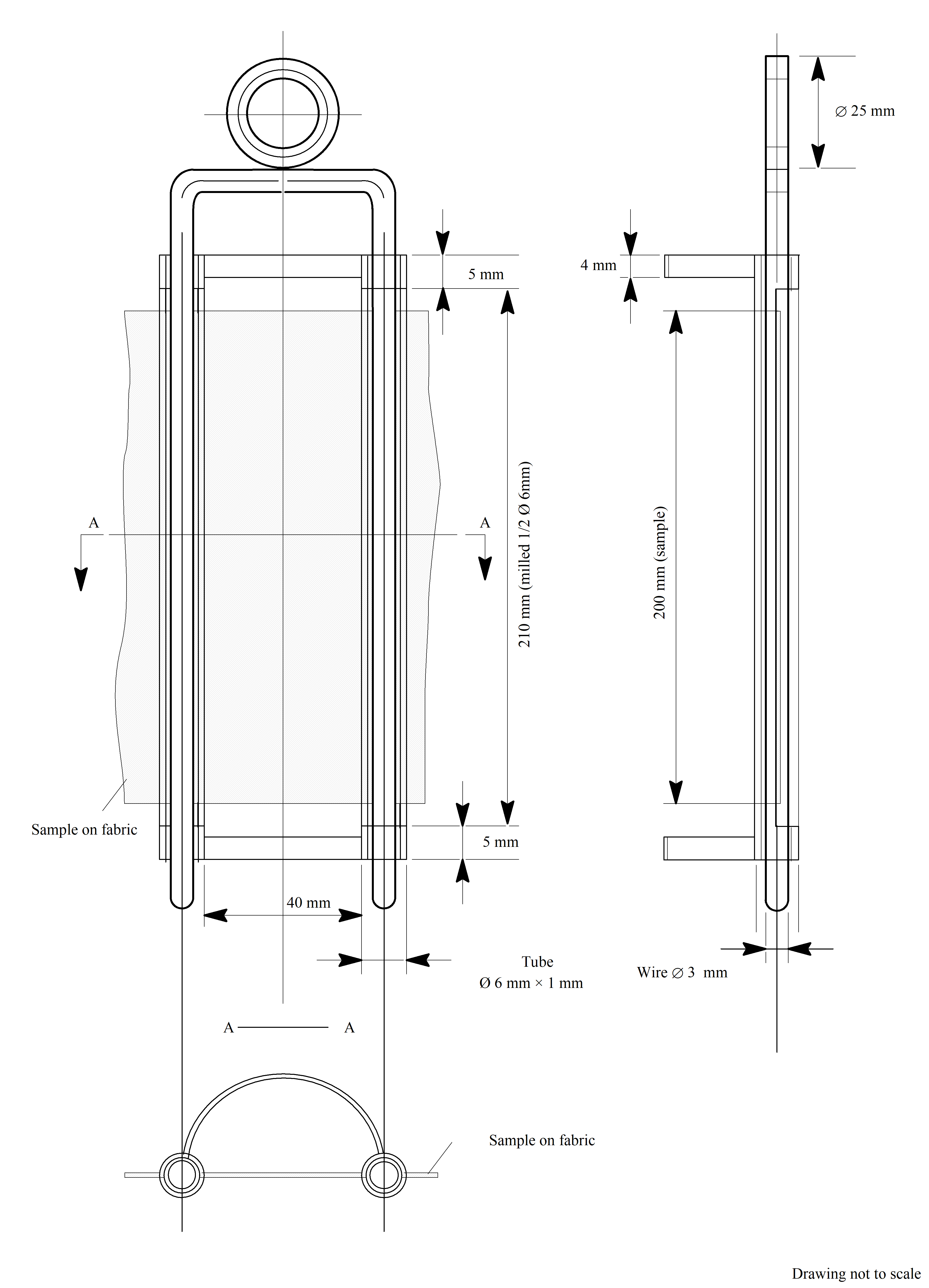 FigureSample holder
Samples from thermoplastic polymer materials
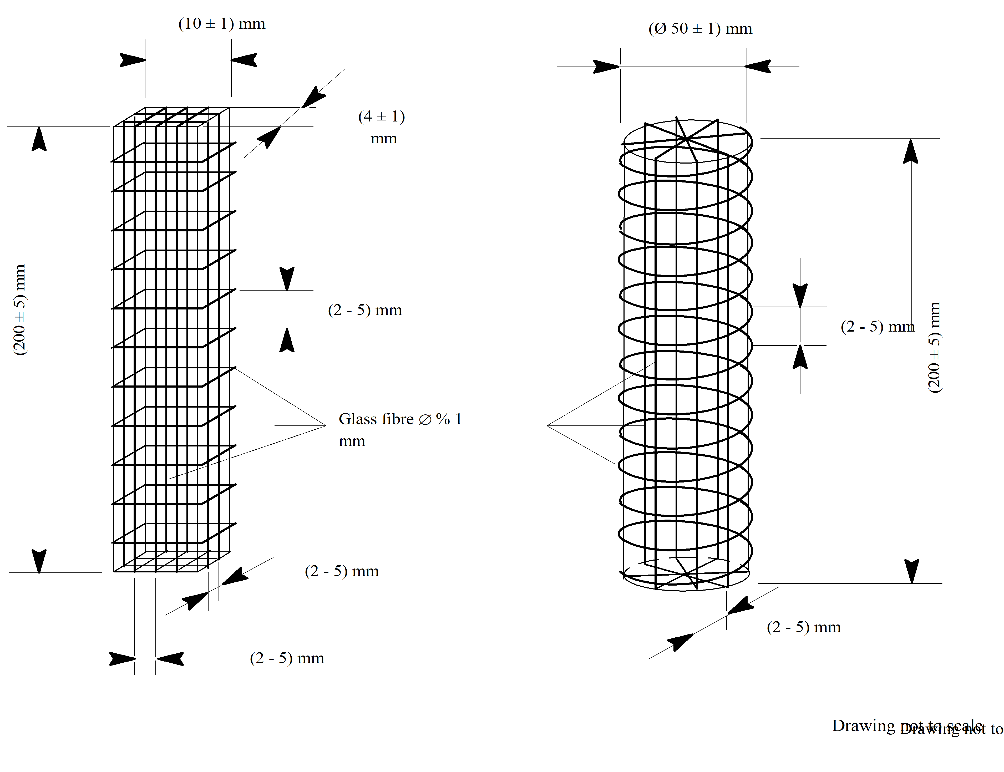 Figure: Samples from thermoplastic polymer materials
Test set up for flammability of electric wires under heated wire conditions at 25 % by volume oxygen
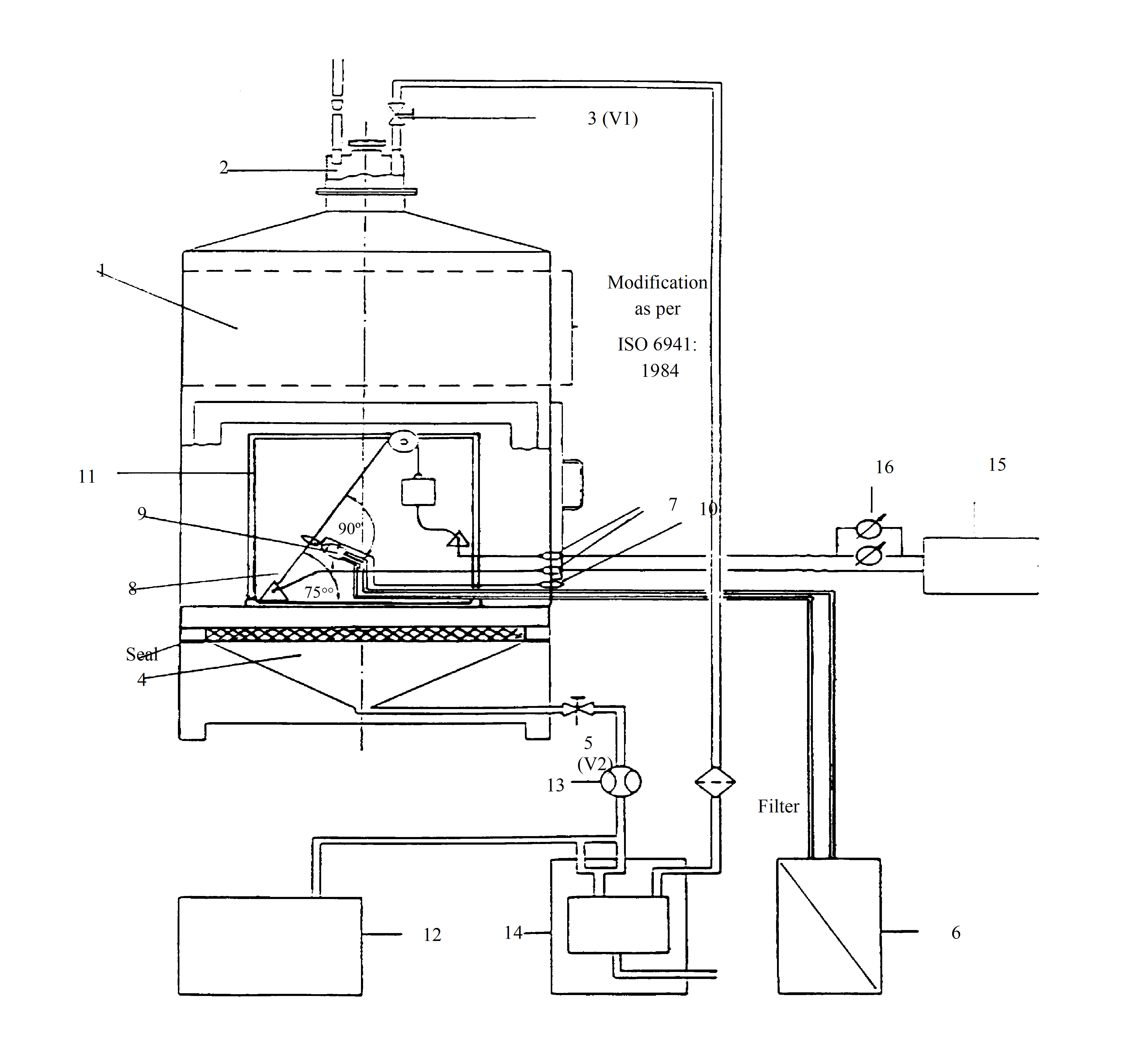 Figure: Test set up for flammability of electric wires under heated wire conditions at 25 % by volume oxygen
Table: Description of test equipment as per Figure D-6
|
Item no.
|
Description
|
Remarks
|
|
1
|
Test chamber
|
DIN 50050 part 1, modified as per Figure D-5
|
|
2
|
Upper adapter
|
• To open/close outlet of item 1
|
|
3
|
Shutoff valve V1
|
To open/close the line for oxygen measurement
|
|
4
|
Distribution unit
|
For distribution of test atmosphere
|
|
5
|
Shutoff valve V2
|
To open/close the atmosphere inlet
|
|
6
|
Burner supply inlet
|
Fuel gas/air supply for burner
|
|
7
|
Feedthrough
|
For electrical current load of test sample
|
|
8
|
Sample and burner assembly
|
60° test
|
|
9
|
Burner
|
Bunsen/Tirrill burner type as Figure D-7
|
|
10
|
Igniter
|
Electrical, of the continuous spark type
|
|
11
|
Support structure
|
Used for example:
|
|
12
|
Test atmosphere supply
|
Gas mixture of nitrogen and oxygen ((25 ± 0,2) % volume fraction of oxygen) at ambient conditions
|
|
13
|
Flowmeter
|
Capable of measuring 2 l/min to 25 l/min
|
|
14
|
Oxygen measuring unit
|
(Optional)
|
|
15
|
Electrical power source
|
Capable of providing a large steady DC current (e.g. 0-100 A) sufficient to raise the conductor temperature to the desired level
|
|
16
|
Measurement of wire temperature
|
Instrument to measure:
|
General arrangement of modified burner and flame dimensions
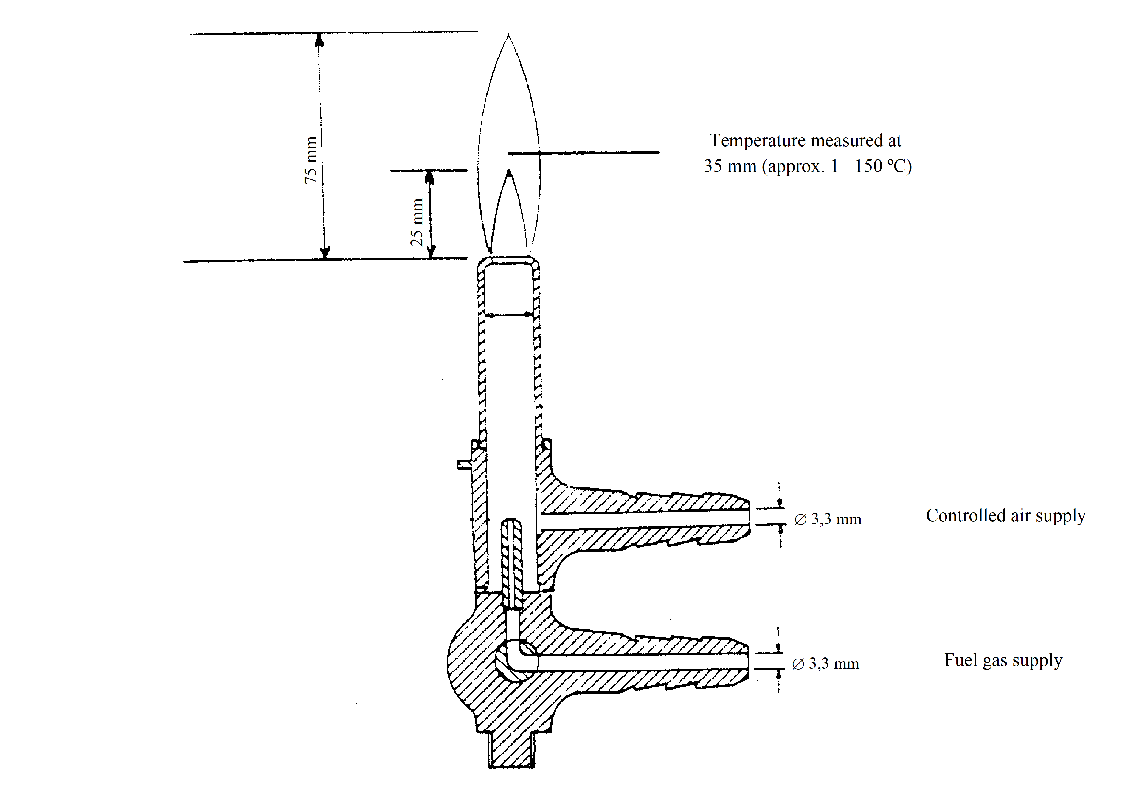 FigureGeneral arrangement of modified burner and flame dimensions
General arrangement of apparatus for flammability test
 FigureGeneral arrangement of apparatus for flammability test
Bibliography
|
ECSS-S-ST-00
|
ECSS system - Description, implementation and general requirements
|
|
NASA STD 6001
|
Flammability, Odor and Offgassing compatibility Requirements & Test Procedures for Materials That Support Combustion
|
|
ZZU.0336.028
|
Standard test method for the determination of the oxygen concentration limit during the combustion of polymer materials (English translation of original Russian title)
|
|
ISO/CD 14624-1
|
Space systems - Test Method for Upward Flammability of Materials
|