
Space engineering
Structural general requirements
Foreword
This Standard is one of the series of ECSS Standards intended to be applied together for the management, engineering and product assurance in space projects and applications. ECSS is a cooperative effort of the European Space Agency, national space agencies and European industry associations for the purpose of developing and maintaining common standards. Requirements in this Standard are defined in terms of what shall be accomplished, rather than in terms of how to organize and perform the necessary work. This allows existing organizational structures and methods to be applied where they are effective, and for the structures and methods to evolve as necessary without rewriting the standards.
This Standard has been prepared by the ECSS-E-ST-32C Working Group, reviewed by the ECSS Executive Secretariat and approved by the ECSS Technical Authority.
Disclaimer
ECSS does not provide any warranty whatsoever, whether expressed, implied, or statutory, including, but not limited to, any warranty of merchantability or fitness for a particular purpose or any warranty that the contents of the item are error-free. In no respect shall ECSS incur any liability for any damages, including, but not limited to, direct, indirect, special, or consequential damages arising out of, resulting from, or in any way connected to the use of this Standard, whether or not based upon warranty, business agreement, tort, or otherwise; whether or not injury was sustained by persons or property or otherwise; and whether or not loss was sustained from, or arose out of, the results of, the item, or any services that may be provided by ECSS.
Published by: ESA Requirements and Standards Division
ESTEC, ,
2200 AG Noordwijk
The
Copyright: 2008 © by the European Space Agency for the members of ECSS
Change log
|
ECSS-E-30 Part 2A
|
First issue
|
|
ECSS-E-30 Part 2B
|
Never issued
|
|
ECSS-E-ST-32C
|
Second issue
|
|
ECSS-E-ST-32C Rev. 1
|
Second issue revision 1
|
Scope
ECSS-E-ST-32C (Space engineering – Structural) defines the mechanical engineering requirements for structural engineering.
This Standard specifies the requirements to be considered in all engineering aspects of structures: requirement definition and specification, design, development, verification, production, inservice and eventual disposal.
The Standard applies to all general structural subsystem aspects of space products including: launch vehicles, transfer vehicles, reentry vehicles, spacecraft, landing probes and rovers, sounding rockets, payloads and instruments, and structural parts of all subsystems.
This Standard may be tailored for the specific characteristics and constraints of a space project in conformance with ECSSSST-00.
Normative references
The following normative documents contain provisions which, through reference in this text, constitute provisions of this ECSS Standard. For dated references, subsequent amendments to, or revisions of any of these publications, do not apply. However, parties to agreements based on this ECSS Standard are encouraged to investigate the possibility of applying the most recent editions of the normative documents indicated below. For undated references the latest edition of the publication referred to applies.
|
ECSSSST0001
|
ECSS system– Glossary of terms
|
|
ECSS-E-ST-32-01
|
Space engineering – Fracture control
|
|
ECSS-E-ST-32-02
|
Space engineering – Structural design and verification of pressurized hardware
|
|
ECSS-E-ST-32-10
|
Space engineering – Reliability based mechanical factors of safety
|
|
ECSS-Q-ST-70-36
|
Space product assurance – Material selection for controlling stress-corrosion cracking
|
|
ECSS-Q-ST-70-37
|
Space product assurance – Determination of the susceptibility of metals to stress-corrosion cracking
|
Terms, definitions and abbreviated terms
Terms from other standards
For the purpose of this Standard, the terms and definitions from ECSSSST0001 apply.
Terms specific to the present standard
A-basis design allowable (A-value)
mechanical property value above which at least 99 % of the population of values is expected to fall, with a confidence level of 95 %
B-basis design allowable (B-value)
mechanical property value above which at least 90 % of the population of values is expected to fall, with a confidence level of 95 %
buckling
not stable equilibrium of a structure under loads applied statically or dynamically
Buckling include snapping of slender beams, buckling of flat plates, buckling of cylindrical panels, three dimensionally curved shells, rib crippling, and skin buckling of a sandwich.composite material
combination of materials different in composition or form on a macro scale
- 1 Composite materials provide improved characteristics not obtainable by any of the original components acting alone
- 2 The constituents retain their identities in the composite.
- 3 Normally the constituents can be physically identified, and there is an interface between them.
- 4 Composites include
- fibrous (composed of fibres, usually in a matrix),
- laminar (layers of materials), and
- hybrid (combinations of any of the above).
- 5 Composites material can be metallic, non-metallic or a combination thereof.
composite structure
structure fully or partially made of composite materials
contributing loads
loads which decrease the margin of safety.
damage tolerance
capability of a structure to resist failure due to the presence of flaws, cracks, or other damage for a specified period of usage without inspection or repair.
design allowable
statistically based strength capability with respect to a failure mode
For example in terms of load resistance, stress resistance, or strain limit with respect to rupture, collapse, detrimental deformation.design factor
factor used in the determination of DLL to account for uncertainties
Design factor accounts for uncertainties related to loads, models and project programmatic aspects (i.e. protoflight approach, uncertainty in launcher environment, maturity of design, growth potential and other design considerations).design limit load (DLL)
limit load multiplied by a design factor
Design factors are defined in ECSS-E-ST-32-10.design load (DL)
design limit load or design yield load or design ultimate load
design parameters
physical features which influence the design performances
According to the nature of the design variables, different design problems can be identified such as: * structural sizing for the dimensioning of beams, shells;
- shape optimization;
- material selection;
- structural topology.
design ultimate load (DUL)
design limit load multiplied by the ultimate safety factor
design ultimate stress
stress caused by the design ultimate load
With this definition no relation exists with ultimate strength.design yield load (DYL)
design limit load multiplied by the yield safety factor
design yield stress
stress caused by the design yield load
With this definition no relation exists with yield strength.detrimental deformation
structural deformation, deflection or displacement that prevents any portion of the structure or other system from performing its intended function or that reduces the probability of successful completion of the mission
dynamic load
time varying load with deterministic or stochastic distribution
effective mass
measure of the mass portion associated to the mode shape with respect to a reference support point
factor of safety (FOS)
factor by which design limit loads are multiplied in order to account for uncertainties of the verification methods, and uncertainties in manufacturing process and material properties
- 1 Factor of safety is synonym of safety factor.
- 2 FS and SF are also recognized abbreviations used for factor of safety
- 3 The factor of safety is a combination of factors according to various sources of uncertainties. Its magnitude is based on proven processes and verification methods for analyses, tests and manufacturing. To account for uncertainties of analysis, higher values of factor of safety are normally used for verification by analysis only. Higher values of factors of safety are also used if higher reliability is desired than was taken in the limit load determination.
failure
rupture, collapse, degradation, excessive wear or any other phenomenon resulting in an inability to sustain design limit loads, pressures (e.g. MDP) and environments
fail-safe structure
structure designed with sufficient redundancy to ensure that the failure of one structural element does not cause failure of the entire structure
No factor of safety is applied to design limit loads in the failure analysis.flaw
local discontinuity in a structural material
For example: scratch, notch, crack, void or pores in case of metallic and homogenous non metallic material; delamination or porosity in case of composite material.generalized mass
mass transformed by the mode shapes into the modal space (i.e. modal coordinates)
limited service life items
hardware item that requires periodic re-inspection or replacement
limit load (LL)
maximum load(s), which a structure is expected to experience with a given probability, during the performance of specified missions in specified environments
maximum design pressure (MDP)
pressure equal to MEOPKmKp
-
1 MDP correspond to design limit loads
-
2 MDP is equal or larger than MEOP.
-
3 Km is a factor which takes into account the representativity of the mathematical models predicting MEOP and it is defined by the entity defining MEOP (for definition of Km see ECSS-E-ST-32-10 ‘Factors of safety’).
-
4 Kp is the project factor (for definition of Kp see ECSS-E-ST-32-10 ‘Factors of safety’)
maximum expected operating pressure (MEOP)
highest pressure that a system or component is expected to experience during its mission life in association with its applicable environment -
1 For mission life see definition in 3.2.29.
-
2 MEOP corresponds to limit loads.
-
3 MEOP includes effects of temperature and acceleration on pressure, maximum relief pressure, maximum regulator pressure and effects of failures within the system or its components. The effect of pressure transient is assessed for each component of the system and used to define its MEOP.
-
4 MEOP includes effects of failures of an external system (e.g. spacecraft), as specified by the customer ,on systems (e.g. propulsion ) or components.
-
5 MEOP does not include testing factors, which are included in ECSS-E-ST-32-02 ‘Structural design and verification of pressurized hardware’ and ECSS-E-ST-10-03 ‘Verification’.
mission life
life cycle from delivery to disposal
primary structure
part of the structure that carries the main flight loads and defines the overall stiffness
proof load
load applied during a proof test
proof test
test of flight hardware under the proof load or pressure, to give evidence of satisfactory workmanship and material quality or to establish the initial crack sizes in the hardware
random load
vibration load whose instantaneous magnitudes are specified only by probability distribution functions giving the probable fraction of the total time that the instantaneous magnitude lies within a specified range
Random load contains no periodic or quasiperiodic constituents. relieving loads
loads which increase the margin of safety
residual stress
stress that remains in a structure after processing, fabrication, assembly, testing or operation
safe life
fracture control design principle, for which the largest undetected defect that can exist in the part does not grow to failure when subjected to the cyclic and sustained loads and environments encountered in the service life
safe life structure
structure designed according to the safe life design principle
scatter factor
factor by which the number of cycles or life time is multiplied in fatigue analysis, fracture analysis, thermal cycling analysis and test in order to account for uncertainties in the statistical distribution of loads and cycles
service life
interval beginning with the last item inspection or flaw screening proof test after manufacturing, and ending with completion of its specified life
secondary structure
structure attached to the primary structure with negligible participation in the main load transfer and overall stiffness
shock load
special type of transient load, where the load shows significant peaks and the duration of the load is well below the typical response time of the structure
(quasi) static loads
loads independent of time or which vary slowly, so that the dynamic response of the structure is not significant
stiffness
ratio between an applied force and the resulting displacement or between an applied moment and the corresponding rotation
structural design
set of information defining the structure, or the process used to generate it
Structural design is an iterative process. The process starts with the conceptual design of possible alternatives which can be considered to satisfy the general performance requirements and are likely to meet the main mission constraints (e.g. mass, interfaces, operation and cost). The various concepts are then evaluated according to a set of prioritised criteria in order to select the designs to develop in further detail. The main purpose of the evaluation is to identify the main mission requirements and to establish whether the selected concepts meet the requirements. The selected concepts are evolved and evaluated in more detail against a comprehensive set of mechanical requirements and interface constraints which are “flowed down” from the main mission and functional requirements.structure
set of mechanical components or assemblies designed to sustain loads or pressures, provide stiffness or stability, or provide support or containment
The structure is usually split into primary and secondary structures.transient load
deterministic load whose magnitude or direction varies with time and for which the dynamic response of the structure is significant
ultimate strength
the maximum load or stress that a structure or material can withstand without incurring rupture or collapse
It is implied that the condition of stress represents uniaxial tension, uniaxial compression, or pure shear.yield strength
maximum load or stress that a structure or material can withstand without incurring a specified permanent deformation or yield
The yield is usually determined by measuring the departure of the actual stressstrain diagram from an extension of the initial straight proportion. The specified value is often taken as a unit strain of 0,002.### Abbreviated terms
For the purpose of this standard, the abbreviated terms of ECSS-S-ST-00-01 and the following apply:
|
Abbreviation
|
Meaning
|
|
AIT
|
assembly, integration and tests
|
|
AOCS
|
attitude and orbit control system
|
|
BIT
|
builtin testing
|
|
CAD
|
computer aided design
|
|
CAE
|
computer aided engineering
|
|
|
computer aided manufacturing
|
|
COG
|
centre of gravity
|
|
DDF
|
design definition file
|
|
DJF
|
design justification file
|
|
DL
|
design load
|
|
DLL
|
design limit load
|
|
DOF
|
degree of freedom
|
|
DRD
|
document requirement definition
|
|
DUL
|
design ultimate load
|
|
DYL
|
design yield load
|
|
ECLS
|
environment control and life support
|
|
EMC
|
electromagnetic compatibility
|
|
FCI
|
fracture critical item
|
|
FEA
|
finite element analysis
|
|
FE
|
finite element
|
|
FM
|
flight model
|
|
FMECA
|
failure mode, effects and criticality analysis
|
|
FOS
|
factor(s) of safety
|
|
FOSU
|
factor(s) of safety at ultimate
|
|
FOSY
|
factor(s) of safety at yield
|
|
FSI
|
fluid structure interaction
|
|
LCDA
|
launcher coupled dynamic analysis
|
|
LL
|
limit load
|
|
MDP
|
maximum design pressure
|
|
MEOP
|
maximum expected operating pressure
|
|
MOS
|
margin of safety
|
|
NDT
|
nondestructive test
|
|
NDI
|
nondestructive inspection
|
|
OTM
|
Output Transformation Matrix
|
|
PFCI
|
potential fracture critical item
|
|
PFO
|
particle fall out
|
|
POGO
|
propulsion generated oscillations
|
|
r.m.s.
|
root-mean-square
|
|
SEP
|
system engineering plan
|
Requirements
Overview
The structural engineering produces a structural product which conforms to its functional and performance requirements by:
aiming for simple load paths,
maximizing the use of conventional materials,
simplifying interfaces, and
providing easy integration.
Lifetime
Structural assemblies and components shall be designed to withstand applied loads due to the mechanical environments to which they are exposed during the servicelife.
Structural assemblies and components shall fulfil, in operation, the mission objectives for the specified duration.
The servicelife shall include the expected events, with at least:
- transportation, handling, testing and storage, and
- all phases of prelaunch, launch, operation and descent. Usually handling tools are provided such that manufacturing, transportation, assembling, testing and storage are not dimensioning cases of the structure.The phases, applicable loads and duration shall be determined using:
- the requirements of the structure (i.e. single mission, expendable, reusable or longterm deployment),
- the effect of all degradation mechanisms upon materials used in the construction (i.e. both terrestrial and space environments and all expected loading regimes), and
- experience with similar structures (e.g. qualification and problems identified inservice). Servicelife evaluations shall determine:
- the inspection and maintenance requirements,
- the item replacement procedure (preventive maintenance), and
- the inspection and repair procedures and intervals (corrective maintenance).
Natural and induced environment
Components and assemblies for space applications shall be compatible with the natural and induced environments, including:
- the on ground, launch and operational environment conditions,
- the atmospheric conditions on earth in which they are manufactured, stored and tested, including corrosion effects,
- the effects of gravitation, and
- the exposure of sensitive materials to manufacturing and atmospheric environments . Provisions (e.g. gravitational compensation and purging) shall be made for the protection of equipment or components.
- 1 The sensitivity of materials to the environment on earth can determine the requirements for quality control procedures.
- 2 The natural environment generally covers the climatic, thermal, chemical and vacuum conditions, cleanliness, levels of radiation and the meteoroid and space debris environment.
- 3 The induced environments cover the mechanical loads induced by ground handling and prelaunch operations, launch, manoeuvres and disturbances, reentry, descent and landing. Additional induced environments include static pressure within the payload volume, temperature and thermal flux variations and the electromagnetic and humidity environments.
Mechanical environment
The mechanical environment shall be defined by static, thermal and dynamic environment loads.
The static and dynamic environment loads shall be defined in terms of constant acceleration, transient, sinusoidal and random vibration, acoustic noise and shock loads.
Loads shall be used in the worst combinations in which they can occur.
The severest loads are experienced during launch, ascent and separation, and, where relevant during reentry, descent and landing.Definition of the mechanical environment shall include the loads which can affect structural integrity and functional performance.
Microgravity, audible noise and human induced vibration
Structural requirements derived from microgravity, audible noise and human induced vibration system level requirements shall be identified.
Load events
The relevant mechanical and thermal load events expected throughout the service life of the structure shall be identified.
Loads shall be defined according to their nature, (i.e. static or dynamic) and their level, occurrence time and duration.
As a minimum the following load events shall be used:
- Ground and test loads:
- handling, transportation and storage loads,
- assembly and integration loads, and
- ground test loads.
- Launch loads as defined by the launch services supplier and including:
- launch preparation,
- operational pressures,
- engine ignition,
- thrust built-up,
- aborted launch
- lift-off,
- thrust (constant or varying slowly),
- aerodynamic loads,
- heat flux from engine and aerodynamics,
- wind and gust,
- dynamic interaction between the structure and propulsion system,
- thrust decay,
- acoustic noise,
- manoeuvres,
- pyrotechnics,
- separation of parts (e.g. stage, fairing and spacecraft), and
- depressurization.
- Inorbit loads:
- operational pressures,
- static and dynamic loads induced by thrusters,
- shocks due to pyrotechnical operation and deployment of appendages,
- thermoelastic loads induced by temperature variations,
- hygroscopicinduced load due to variations in moisture content,
- microvibrations induced by moving elements (e.g. momentum wheels) and thrusters,
- micrometeoroids and debris,
- docking,
- berthing, and
- crew induced loads (e.g. on handles, rails and by movements).
- Reentry, descent and landing:
- aerodynamic loads and thermal fluxes,
- parachute ejection and deployment shocks,
- operational pressures,
- landing loads, and
- impact loads.
Combined loads
Load combination rules shall be defined according to specified load events by establishing the loads to be combined, their level and mathematical combination procedures
For example mathematical combination procedures like linear superposition or root of the sum of the squares.Load application sequence shall be defined.
For example to account for any non-linear effect depending on load application sequence.Factors of safety for combined loads shall be defined at yield and ultimate level, and for the tests.
Relieving loads which are independent from contributing loads shall be combined at their minimum operating value without any design factor nor FOS.
This requirement aims at avoiding overestimation of relieving effects due to combination of loads.### Limit loads
The limit loads are derived as follows:
- For cases where a representative statistical distribution of the loads is known, the limit load shall be defined as the load level not being exceeded with a probability of 99 % and a confidence level of 90 % during the servicelife.
- For cases where a statistical distribution of the loads is not known the limit loads shall be agreed with the costumer. It is good practice to determine the loads using conservative assumptions.* For pressurised systems, the maximum expected operating pressure (MEOP) shall be part of the limit loads. For Gaussian distributed random loads for verification, with a zero mean value, the limit load contribution shall be derived as standard deviation multiplied by three, i.e. 3 × root-mean-square (r.m.s.).
Design limit loads
The design limit loads shall be derived by multiplication of the limit loads by the design factors.
Design factors shall be system defined.
For pressurised systems, the maximum design pressure (MDP) shall be part of the design limit loads.
Functionality
Overview
For the design, manufacturing, verification, operation and maintenance of metallic and non-metallic pressurized hardware see the requirements of ECSSEST3202. For fracture control programme see ECSS-E-ST-32-01.
Strength
The structure shall withstand the design limit loads without failing or exhibiting permanent deformations that can endanger the mission objectives.
Local yielding
For metal structures or metal structure components local yielding may exist, provided it does not cause overall permanent set, instability or fatigue failure of the structure
Buckling
The stability (i.e. no buckling) of the structure shall be verified for the design loads.
Local buckling shall be prevented unless:
- the buckling is reversible, and
- the resulting stiffness and deformations still conform to the structural and functional requirements, and
- a post-buckling investigation (by analysis or test) demonstrates positive margins against failure.
Stiffness
Stiffness requirements under the specified load and boundary conditions shall be identified.
Stiffness is often expressed in terms of a minimum natural frequency requirement.The stiffness of subassemblies and components and interfaces shall be such that the structural and functional performance requirements are met
For example avoiding deformations leading to violations of specified envelopes, gapping at joints, the creation of inefficient load paths and dynamic coupling with other subsystems e.g. Attitude and Orbital Control System.### Dynamic behaviour
The natural frequencies of a structure shall be within specified bandwidths preventing dynamic coupling with major excitation frequencies
For example launch vehicle fundamental frequencies.### Thermal
Constraints imposed by the thermal design and impacting the structure shall be identified.
The temperatures and temperature variations and gradients during all phases of a mission, including manufacturing and storage, shall be used, both in the material selection and in the design in order to achieve the specified functional and structural performance.
Damage tolerance
Damage tolerance design principles shall be applied.
Design principles can include failsafe design (redundancy) of attachment points, and damage tolerant materials.The resistance of the structure against manufacturing defects and the result of accidental damage (e.g. low energy impact) shall be taken into account in the design.
A structure is considered tolerant to damage if the amount of general degradation or the size and distribution of local defects expected during operation does not lead to structural degradation below specified performance.### Tolerances and alignments
The accuracy of the tolerances applied to the mechanical design shall guarantee conformance to geometrical interface requirements.
The impacts of the assembly alignment and pointing accuracy requirements on the angular and position tolerances shall be identified.
In cases where alignment adjustability is specified, either at assembly level or at spacecraft level, these provisions shall be included in the mechanical design together with the devices (e.g. alignment cubes) for measurement or checking of the alignment.
Electrical conductivity
Structural requirements derived from electrical conductivity requirements shall be identified.
Lightning protection
The structure shall be designed to
- dissipate static electrical charges,
- provide electromagnetic protection, and
- provide means of diverting electrical current arising from lightning strike so as not to endanger the vehicle.
Electromagnetic compatibility
Structural requirements derived from electromagnetic compatibility requirements shall be identified.
Dimensional stability
Impact of system requirements on dimensional stability of the structure shall be identified.
Dimensional stability requirements address the short, medium and long term alignment stability of a space structure under the operational environment.The mechanical design of a structure shall ensure that no loss of alignment caused by the action of applied loads and material stability can jeopardise or degrade the mission objectives.
Structure stability can be affected for example by launch loads, deployment loads, thermal and moisture release.### Interface
The design of structural assemblies shall be compatible with internal and external interfaces, which can affect or be affected by adjacent systems, subsystems or assemblies.
Mechanical subsystem internal interfaces shall include:
- thermal control,
- mechanisms,
- ECLS,
- propulsion,
- pyrotechnics,
- mechanical parts, and
- materials. External interfaces shall include:
- spacecraftlauncher interface,
- human factors and ergonomics
- interfaces with equipment, optics and avionics,
- rendezvous and docking, robotics,
- ground support equipment for pre-flight and post-flight operations, and
- support equipment for in-orbit operations. Interfaces shall be explicitly defined with respect to the following:
- Design requirements. These include areas, volumes, alignments, surface finishing and properties, tolerances, geometry, flatness, fixations, conductibility, constraints imposed by the launcher (e.g. geometric, static and dynamic envelopes) and by design concepts (e.g. thermal and optical design), mass and inertia properties.* External loads applied to the interfaces, including temperature effects and overfluxes caused by adjacent structures.
- Global and local stiffness.
- Electrical, magnetic and radio frequency aspects, where applicable
Design
Inspectability
To ensure structural integrity, the requirement to inspect a component, assembly or structure shall be met during the following:
- at various stages throughout manufacture,
- at various stages during assembly,
- after testing, and
- inservice.
An NDI policy shall be defined and incorporated into the design process using the inspectability of parts and access for inspection equipment and personnel.
For structures subject to fracture control the NDI policy shall be consistent with the assumption made for the fracture control verification, and as specified in ECSS-E-ST-32-01.
Interchangeability
All parts or subassemblies identified by an item number shall be functionally and dimensionally interchangeable with items which are identically numbered.
It is not guaranteed that parts or subassemblies which are match drilled during assembly are interchangeable.### Maintainability
The mechanical design shall be performed in such a way that assembly, integration and repair and maintenance activities can be carried out with tools and test equipment agreed with the customer.
It is good practice to minimize the number of special tools and equipment to minimize cost.The maintenance activity during storage and ground life should be avoided.
The maintenance programme shall
- include a maintenance protocol, and
- define measurable parameters for all operations, and during all project phases, including at least the following:
- meantimetorepair,
- limitedlife,
- fault detection and isolation capability,
- spares requirements, and
- ground storage requirements.
The results of the maintenance programme evaluation shall
- avoid alterations and replacement of parts,
- form the criteria with which various concept designs are evaluated. Structures that are not accessible shall be maintenance free during service-life.
Dismountability
The mechanical design shall enable removal and replacement of:
- secondary structures,
- equipment, and
- payload.
Mass and inertia properties
Mass and inertia properties of the structure shall be determined during all phases of the design
Mass and inertia properties can be estimated, calculated or measured.Mass and inertia properties shall be compliant with the mass budget allocation.
The mass and inertia properties of a structure comprise its mass, the location of its centre of gravity, its moments and products of inertia, and, where applicable, its balancing masses.### Material selection
Overview
For requirements on material selection, see ECSS-Q-ST-70 and ECSS-E-ST-32-08.
Corrosion effects
The material selected for corrosion resistance shall be compatible with:
- the specific environment,
- interaction with contained fluid,
- design, fabrication, storage of individual and assembled components,
- interactions with dissimilar materials, and
- susceptibility to fretting and crack initiation.
Corrosion can be regarded as any deterioration in the physical and chemical properties of a material due to the environment to which they are exposed.In cases where the behaviour of a material in a specific environment is not known, corrosion tests of representative materials (composition and condition) shall be performed, either under the service conditions, or in more severe conditions (accelerated testing).
For alloys, and their weldments, not included in table “Alloys with high resistance to stress–corrosion cracking” of ECSS-Q-ST-70-36, their characteristics on susceptibility to stress-corrosion cracking shall be demonstrated by test in conformance with ECSS-Q-ST-70-37. - 1 These materials have been tested and demonstrated to have a high resistance to stress-corrosion cracking and therefore can be used for this purpose.
- 2 Metals, alloys and weldments not present in table “Alloys with high resistance to stress–corrosion cracking” of ECSS-Q-ST-70-36 can be approved for structural applications by means of the stress-corrosion evaluation form specified in the Annex A of ECSS-Q-ST-70-36.
Mechanical parts selection
For requirements on selection of mechanical parts, see ECSS-Q-ST-70.
Material design allowables
For structural material, design allowables shall be statistically derived covering all operational environments.
The scatter bands of the data shall be derived and design allowables defined in terms of fractions of their statistical distribution with A-basis or B-basis specified levels of reliability and confidence.
For each type of test the minimum number of test specimens shall be:
- ten (10) to establish Avalues, and
- five (5) to establish Bvalues.
If the material is delivered in several batches, the design allowables test programme shall evaluate the variations from batch to batch by performing sample tests at regular intervals during the production sequence.
In the cases specified in d) above, preliminary design allowables may be based on the initially small sample size, and upgraded as the sample size increases by tests of newly arriving batches. - 1 For material testing requirements, see ECSS-E-ST-32-08 and ECSS-E-HB-32-20.
- 2 Probabilistic descriptions of the strength distribution of materials are usually based on the normal, lognormal or the Weibull distribution. Regardless of the kind of distribution, distribution curves and fractiles cannot be uniquely identified due to the data scatter. The values are assumed to lie within an interval bounded by upper and lower confidence limits. When design allowables are deduced from a regression line based on a small number of test specimens the confidence in such allowables is low. Larger numbers of test specimens generally do not change the shape of the regression line, but the confidence in the statistical evaluation increases.
- 3 The test database can be broadened by the inclusion of compatible data from acceptance and development tests.
Metals
All design allowables for metals shall be defined by their Avalues.
For unpressurized metal structures, B-values may be used in redundant structure in which the failure of a component can result in a safe redistribution of applied loads to other load–carrying structures.
All other metal material properties shall be defined by average values.
Nonmetallic materials
Glass and ceramics
Design allowables for glass and ceramics shall be derived through a probabilistic approach, covering all size effects.
For brittle materials such as glass and ceramics the lack of ductility results in very low failure strains. The large scatter observed in component testing is primarily caused by the variable severity of flaws distributed within the material (volume flaws) or flaws extrinsic to the material volume (surface flaws). The different physical nature of the flaws result in dissimilar failure response to identical external loading conditions. Due to the random distribution of flaws the failure of a complex structural part can be initiated not only at the point of highest stress.#### Nonmetallics other than glass and ceramics
Design allowables for other non-metals, (stress or strain) shall be defined by their Avalues.
For unpressurized non-metallic structures, B-values may be used in redundant structure in which the failure of a component can result in a safe redistribution of applied loads to other load–carrying structures.
The material properties other than those specified in 4.5.10.2a and 4.5.10.2b shall be defined by average values.
Composite materials
All design allowables for composite materials (stress or strain) shall be defined by their Avalues.
For unpressurized structures in composite materials, B-values may be used in redundant structure in which the failure of a component can result in a safe redistribution of applied loads to other load–carrying structures.
For structures made in composite materials, a progressive failure analysis methodology can be used to demonstrate that the material is intrinsically redundant, i.e. it maintains the required load carrying capability after initial damage or failure of one component (e.g. after failure of the most critical lamina).All the material properties other than those specified in 4.5.11a and 4.5.11b shall be defined by their average values.
The strength and stiffness of composite fibre reinforced materials are functions of fibre properties, matrix properties, fibre content and orientation of fibres. The properties of composites are determined by both fibres and matrix. By placing fibres in different directions, the material properties can range from highly anisotropic to quasi isotropic.### Adhesive materials in bonded joints
All design allowables for adhesive materials in bonded joints (stress or strain) shall be defined according to standards agreed with the customer.
Ablation and pyrolysis
Impact of material changes due to ablation and pyrolysis shall be identified.
In cases where the behaviour of a material in a specific environment is not known, ablation and pyrolysis tests of representative materials (composition and condition) shall be performed, either under the service conditions, or in more severe conditions (accelerated testing).
Micrometeoroid and debris collision
Pressurised structures, tanks, battery cells, pipes, electronic boxes and other specified equipment shall be protected from micrometeoroid and debris impact in order to prevent loss of functionalities.
The selection and design of material and debris protection systems shall be based on a specified probability of survival.
For a given hardware design and configuration, the probability of survival is influenced by the probability of impact, critical debris size, material response to hypervelocity impacts, impact face; back face (spalling), mission duration, spacecraft orientation and multiple impacts.### Venting
Provision shall be made in the design of the structure for venting.
In order to prevent a buildup of excess pressure and to reduce the time to evacuate the structure, a minimum ratio of venting-area to enclosed-volume is usually needed for venting.In case that provision a. is not made, the structure shall withstand build-up pressure (including safety factors).
The openings for venting shall be compatible with the purging system gas supply pressure and flow rate.
The openings for venting can be used to prevent contamination or risk of explosion.### Margin of safety (MOS)
Margins of safety (MOS) shall be calculated by the following formula:
![]() Loads can be replaced by stresses if the load stress relationship is linear.All margins of safety shall be positive.
Loads can be replaced by stresses if the load stress relationship is linear.All margins of safety shall be positive.
The margins of safety for combined loads shall be computed by the following procedure:
- define the load combination applied at a certain design level (limit, yield or ultimate), according to the specified FOS for combined loads;
- calculate the margin of safety as: Equation MOS = -1
where , called reserve factor, is the ratio between design allowable and design load.
MOS shall be computed by accounting for interactions of different types of failures (e.g. failure of a bolt due to shear and tension)
The following “interaction equation” is normally used to compute for interacting failure types: ![]() where , , , and are experimental exponents and Ri are the ratios between the i-th DLL x FOS and the allowable load (which causes the failure if the i-th load is applied alone)### Factors of safety (FOS)
where , , , and are experimental exponents and Ri are the ratios between the i-th DLL x FOS and the allowable load (which causes the failure if the i-th load is applied alone)### Factors of safety (FOS)
Overview
The selection of appropriate factors of safety for a specific structural element depends on parameters, which are related to loads, design, structural verification approach, model philosophy and manufacturing aspects. Such aspects include the following:
pressurized structures,
human presence,
flight hardware or ground support equipment,
material type,
joints, bearings, welds,
verification by test,
verification by analysis only,
thermal loads,
ageing effects,
emergency loads,
fail-safe structure verification, and
dimensional stability.
FOS requirements
Factors of safety shall be determined considering the uncertainty of loads, design, material, manufacturing and verification parameters
Factors of safety listed in ECSS-E-ST-32-10 and ECSS-E-ST-32-02 shall be applied.
Scatter factors
A scatter factor of four (4) shall be used in fatigue analysis.
- 1 The scatter factor is applied to the number of cycles of a certain load level in order to cover the uncertainties of loads and material properties. Usually for metallic materials a scatter factor of 4 is applied. However, for specific applications (e.g. pressure vessels and low cycle fatigue) higher values are commonly used (e.g. 5 for pressure vessels).
- 2 For composite materials in some cases a factor on the stress (e.g. 1.15) is defined instead of a scatter factor on the load cycles”
- 3 The number of cycles can be based on the number of possible repetitions of tests (e.g. 1 qualification vibration plus 3 possible repetitions) specified by the project.
Verification
Overview
For general requirements on verification, verification programme and verification methods, see ECSS-E-ST-10-02.
Verification by analysis
General
Analysis methods shall be agreed between customer and supplier.
Different state of the art analysis methods are available, such as handbooks, standards or validated numerical solutions.A mathematical model (e.g. finite element model) shall be developed for primary and secondary structure.
A mathematical model shall be developed and delivered for launcher coupled dynamic analysis (LCDA).
It shall be demonstrated that the analysis tools used are adequate for the intended purpose.
A justification of assumptions made in tools, methods, models and input data shall be provided.
The influence of tolerances (including overall dimensions and thickness) shall be assessed whenever potentially critical.
All analysis data shall be traceable, and the organization responsible for the analysis shall provide procedures to ensure data traceability during the life of the product.
Modelling aspects
It shall be demonstrated that the mathematical models is adequate to perform the foreseen analysis.
- 1 Finite element mathematical models meet the requirements detailed in ECSS-E-ST-32-03.
- 2 Analysis is based on mathematical models which are representative of the structural behaviour. These models help the designer to assess how the design fulfils structural requirements and gives an insight on how to improve the design.
- 3 The mathematical models enable preparation of experimental testing and verification of requirements not demonstrable by tests, e.g. through coupled analysis.
- 4 The mathematical models help in defining load cases or combination of load cases.
- 5 The mathematical models can also give designers insight on sensitivity of the design with respect to uncertainties.
Mathematical models shall be validated by correlation with test results for specific needs.
Static analysis
Static analysis shall be performed to verify that the structural responses (e.g. displacements, forces, stresses and internal loads) to (quasi) static loads conform to the structural requirements.
The static analysis shall use representative load introduction, load distribution and boundary conditions.
Provisions shall be made to include the effects of residual stresses due to the manufacturing process (e.g. welding).
Static analysis shall take into account stress concentrations.
Stress concentrations essentially take place in areas with steeply varying shape or section and with notches (macro and micro stress raisers). For metals stress concentrations are known to have a detrimental effect on fatigue lifetime. For fibre reinforced plastics stress concentrations have a detrimental effect on static strength. #### Modal analysis
Modal analysis shall be performed to
- verify that the structure conforms to the natural frequency requirements, and
- determine associated modal characteristics (e.g. natural frequencies, mode shapes, generalized and effective masses).
Pretension and spin effects shall be included.
For large lightweight structures (e.g. solar arrays, antenna reflectors), the effect of the surrounding air shall be included in the analysis.
Dynamic response analysis
Dynamic response analysis shall be used to verify the structural response due to excitations (e.g. force or motion inputs via mechanical interfaces, thermal input such as eclipse transitions, spinner centrifugal forces, and possible combination thereof) either in the frequency domain (e.g. sine and random) or time domain (transient) according to the definition of loads.
Coupled loads analyses are performed to verify the loads resulting from dynamic behaviour of structural assemblies as follows:
- The mathematical models applied in coupled analyses shall represent the structural assemblies by characterization of the dynamic parameters, namely natural frequencies, mode shapes, associated generalized and effective masses, and damping.
- The characterization of natural frequencies with small effective masses (e.g. multilayer insulation) need not be performed if it can be shown that these modes do not participate to the overall dynamic behaviour.
Acoustics analysis
Acoustic analysis shall be used to calculate the characteristics of the pressure field due to acoustic sources.
Response analysis shall be performed to verify structural response to acoustic fields including acoustic fatigue.
Fluid structure interaction (FSI)
The structure shall be verified against the effects of the interaction with fluids (e.g. sloshing, POGO, cavitation effects and pressure fields).
Fatigue analysis
Fatigue analysis shall be performed to verify that fatigue defect (crack or delamination) initiation or propagation resulting in structural failure or functional degradation cannot occur throughout the service life of the structure.
Effects of stress concentrations shall be included in the analysis.
The life of the structure shall be verified for the specified service life multiplied by the specified scatter factor considering the most unfavourable load sequence within each event.
Design limit loads (multiplied by factors of safety specified by the customer for fatigue) shall be used for fatigue analysis.
Alternate, permanent, and acoustic loads and their combination and sequence shall be used to perform the fatigue analysis.
- 1 Fatigue analysis normally uses a cumulative damage approach which estimates fatigue life from stress spectra and fatigue material allowables (S-N or Wöhler curves).
- 2 The following safety factors are usually applied for fatigue analysis: 1,0 for metallic materials, and 1,15 for composite materials.
Fracture control analysis
For fracture control analysis requirements, see ECSS-E-ST-32-01.
Buckling analysis
Buckling analysis shall be used to predict the loads at which the onset of structural instability occurs.
For cases where elastic fully reversible buckling is accepted, postbuckling behaviour shall be analysed.
Effects on stability of boundary conditions, defects and geometrical imperfections in the structure shall be included in the buckling analysis.
Geometrical imperfections refer to any deviation from the nominal shape including effect due to assembly tolerances.Minimum gauge shall be used for buckling analysis.
Thermo-elastic and Hygro-thermal analysis
Thermo-elastic analysis shall be performed to compute stresses and deformations due to occurring temperatures.
To perform thermo-elastic analysis temperature distributions defined by thermal analysis are usually mapped on the structural model.Hygro-thermal analysis shall be performed to compute deformations due to occurring moisture release or absorbtion.
Bonded joints
The analysis of bonded joints shall be performed in accordance with standards or procedures agreed with the customer.
- 1 For the mechanical characteristics of the bonded joints the following is usually taken into account:
- the influence of the characteristics of the adhesive,
- the material of the adherents
- any surface treatments,
- the dimensions of the bonded areas, and
- the relative stiffness of the parts.
- 2 For bonded joints, see ECSS-E-HB-32-21.
Bolted joints
Bolted joints shall be analysed according to standards or procedures agreed with the customer.
For bolted joints, see ECSS-E-HB-32-23.#### Welded joints
Welded joints shall be analysed according to standards or procedures agreed with the customer.
The analytical verification of welded joints usually takes into account the following:* stress concentrations,
- type and quality of the weld,
- local maximum allowable geometrical defects (e.g. mismatch and peaking), and
- residual stresses and material characteristics changes due to local heating and cooling.
Riveted joints
Riveted joints shall be analysed according to standards or procedures agreed with the customer.
Inserts
Inserts shall be analysed according to standards or procedures agreed with the customer.
- 1 Inserts are generally used in sandwich constructions with cores of low strength.
- 2 For inserts, see ECSS-E-HB-32-22.
Aeroelastic analysis
Aeroelastic analysis shall be used to assess the interaction between the aerodynamic flow and the structure.
Mass and inertia properties
The inertia properties shall be computed according to the specified accuracy using the inertia matrix of individual components.
The inertia properties shall be monitored and presented in a mass budget report issued on a regular basis agreed with the customer.
A breakdown of mass to component level shall be given together with mass contingency estimates based on the design maturity.
The mass and inertia data shall include the following:
- mass,
- co-ordinates of the centre of mass with respect to specified co-ordinate system,
- moments of inertia with respect to specified co-ordinate system, and
- the principal moments of inertia and their orientation with respect to specified coordinate system.
Alignments
It shall be demonstrated by analysis that alignment requirements can be met with the chosen design tolerances.
Dimensional stability
Short, medium and long term effects shall be included in the analysis to determine the dimensional stability of the structure.
A stability budget shall be established and the contributors shall be identified, analysed and allocated.
Examples of contributors affecting dimensional stability are: thermoelastic effects, moisture release, inorbit loads, zerogravity environment, microvibrations, material ageing (material property changes), material dimensional instability, setting effect and spin effect. #### Micro-vibrations, microgravity, audible noise and human induced vibration analysis
The structural responses at the locations of sensitive receivers due to disturbance sources shall be analysed.
Disturbance sources are e.g. reaction wheels, human induced vibrations, microcracking.”### Verification by test
Overview
For general requirements and definitions on verification by test, see ECSS-E-ST-10-02 and ECSS-E-ST-10-03.
General
The test objectives and success criteria shall be specified.
The adequacy of the test procedure with regard to the test objectives shall be verified before the test.
Checking of the test conformance with regard to the test procedure shall be performed after the test.
The impact of deviations on the adequacy of the test with respect to the test objectives shall be evaluated.
Differences between test conditions and expected operating conditions (e.g. boundary conditions, gravity and atmosphere) shall be identified.
Correction factors shall be applied to test loads to correct the effects of the differences identified in clause e. on the operating conditions.
The test results shall be evaluated with respect to the requirements to be verified.
Test data shall be used to validate mathematical models for specific needs.
Model philosophy
One of the following test model philosophies shall be applied:
- prototype approach,
- protoflight approach, or
- hybrid approach
Development tests
For materials, design concepts and expected critical parts not documented in previous applications, development tests shall be performed to:
- evaluate the design choices,
- support and check analysis methods,
- determine the failure modes,
- support qualification and acceptance test definition.
- 1 Development tests can be performed on:
- specimens (e.g. to test material properties),
- structural parts or components, or
- the whole structure.
- 2 Development tests can include static tests and other tests (e.g. fracture mechanics test, thermal distortion test).
Qualification tests
Qualification tests shall be performed to verify that the structure design and manufacturing technique fulfil specification requirements.
Qualification tests can include static tests, dynamic and acoustic tests, and other tests (e.g. thermal stress test).Qualification test shall account for the worst hardware characteristics which can be present in a flight unit but are not present in the test unit (e.g. by means of dedicated correction factors).
Acceptance tests
Acceptance tests shall be performed on the flight hardware.
- 1 Acceptance tests are performed to demonstrate that no workmanship defect prevents a structure item to fulfil specification requirements.
- 2 Acceptance tests can include static tests (including proof pressure tests), dynamic and acoustic tests, and other tests (e.g. dimensional stability tests)
- 3 Acceptance tests can include the following types of tests:
- proof pressure tests of pressurized hardware;
- tests of composite structures (see clause 4.6.4);
- proof tests on sandwich inserts;
- structure related functional tests (e.g. mechanism or leakage tests);
- dynamic tests on equipped sub-assemblies.
Static test
Static test shall be performed to:
- demonstrate that the structure is able to carry a specified load type and level (e.g. qualification load) without failure;
- verify the structural stiffness;
- verify the static mathematical model (at a specified load level).
Failure test (e.g. by rupture or buckling) shall be performed to determine the load-carrying capability of the structure and to confirm type of the real failure mode.
The following requirements apply to static test conditions: - boundary conditions shall be demonstrated to be representative of flight boundary constraints or alternatively test forces on boundary constraints shall be measured;
- dummy structure used in the test shall be demonstrated to be representative as regard the stiffness and the constraints of the replaced flight component.
Modal survey test
Modal survey test shall be performed to verify the modal characteristics.
See ECSS-E-ST-32-11.#### Dynamic tests: sine, random, shock
Dynamic tests (sine, random, shock) shall be performed to verify:
- the dynamic behaviour, in terms of accelerations and interface forces (including units and appendages)
- the compliance to the stiffness requirements, and
- the strength and alignment stability under dynamic loads.
Acoustic test
Acoustic tests shall be performed to verify:
- the ability of the structure and its equipment to withstand the vibrations induced by the specified acoustic field.
- the random dynamic design environment for subsystems and equipment.
Fatigue and fracture test
Fatigue and fracture tests shall verify that the structure can survive, without degradation, at least the predicted service life cycles with the specified scatter factor.
Fatigue tests shall verify that the cyclic loads do not cause cracks or crack-like defects that endanger integrity of the structure or change the behaviour in an unacceptable manner.
Fracture tests shall verify that initial cracks or crack-like defects which can be present in the structure after application of NDI do not propagate, due to cyclic or constant loading, up to a critical value, which causes structural failure.
Micro-vibrations, microgravity, audible noise and human induced vibration tests
The conformance to requirements on micro-vibrations and microgravity disturbances originating from the structure shall be verified by test.
Structural and acoustic to structural transmissibilities shall be validated by test.
Non destructive inspection and test
A nondestructive inspection and test shall be performed on the structure to verify that no defect (e.g. crack, delamination, porosity, impact damage, scratches) larger than the size specified by requirements (e.g. life or leak) are present.
Nondestructive tests evaluate or quantitatively measure properties or detect defects in materials or structural components or whole structures which do not cause a permanent change to the item under test, e.g. visual inspection, ultrasonics, holography, eddy current and leak test.#### Thermo-elastic test
The adequacy of the structure to withstand thermal loads shall be verified by test.
Conformance of thermo-elastic distortion to requirements shall be verified by test.
Thermal cycling test
Thermal cycling tests shall be performed in order to verify that the structure is capable to survive without failure all of the thermal cycling loads expected during its service life.
Thermal cycling temperature range shall be increased to account for uncertainties in the thermal analysis.
The following scatter factor shall be applied on the number of cycles for the thermal cycling tests:
- for launchers, re-entry vehicles and spacecraft subject to a low number of operational thermal cycles:
- a scatter factor of 4, for cycling within flight temperature ranges;
- a scatter factor of 2 for cycling within the qualification temperature ranges;
- for other spacecraft subjected to a large number of operational thermal cycles a scatter factor of 1,5. Thermal cycles for year range from 100 for geostationary orbits to 6000 for low Earth orbits.#### Ageing test
Ageing tests shall be performed to identify variations of the material properties as a function of time and environment.
Variations identified in clause a. shall be used to assess the structural design.
Contamination test
Contamination tests shall determine the particle fall-out (PFO) on specified spacecraft systems.
Mass and Inertia properties measurement
The mass and inertia properties of the structure shall be measured to the specified accuracy.
Alignment checks
Alignment checks shall be performed in order to verify the relative position and movements between parts during manufacturing, assembly and verification.
Dimensional stability tests
The dimensional stability of the structure in the environment of the operational conditions shall be verified by test.
The conformance of long term changes of material properties to specification (e.g. moisture release, ageing and creep) shall be verified by test.
Geometrical control
Dimensions and tolerances shall be controlled during and after manufacturing to conform to the functional requirements.
Interface verification
Interface verification shall be performed by:
- inspection (including geometrical control) of the manufacturing drawings and parts with respect to the interface requirements, and
- with the aid of fit checks of interfacing structural components.
Aerothermodynamic test
Aerodynamic and aerothermodynamic tests shall be performed to verify the behaviour of the vehicle or a part of it during flight in the atmosphere.
Tests performed with subscale models shall be verified for their representativity with respect to the flight item.
Aeroelastic test
Aeroelastic tests shall be performed to verify the analytically predicted behaviour for each flight configuration and to determine application limits.
Aeroelasticity tests are performed on subscale and full scale models and on flight vehicles on ground and in flight.#### Lightning protection verification
Test and inspection according to agreed procedures shall be performed to ensure the functioning of the lightning protection system.
Verification of composite structures
In addition to requirements from 4.6.1 to 4.6.3, the requirements 4.6.4b until 4.6.4e shall be applied to composite structures.
For all composite structures, acceptance tests shall be performed at 1,0 times the limit load.
Except in the case specified in 4.6.4d, composite structure acceptance tests shall be performed at component level or on fully assembled structure.
If tests are performed at assembly level, measurements shall be performed to verify the load paths in the tested composite component.
Composite structure may be exempted from acceptance testing if agreed with the customer.
The acceptance tests are not performed if it can be shown that the manufacturer of the composite component has:* extensive experience and a successful history of manufacturing similar design,
- proven application of the process specifications and trained personnel,
- proven non-destructive techniques to validate the quality and integrity of the finished article.
Acceptance tests shall be performed in case of transfer of manufacturing of composite structure to a new manufacturer.
Production and manufacturing
General
The production engineering of space structures shall ensure that the structure, and all its component parts, can be manufactured in the way intended to conform to the quality, reliability and reproducibility requirements.
The production of space structures includes the following:* procurement, which covers - materials,- components, and - parts,
- manufacturing and fabrication of components,
- assembly of components, and
- the assembly of substructures to form the final structure, either within the factory or at the launch site.
Manufacturing process
The selected manufacturing processes shall be qualified before manufacturing of flight or flight-representative hardware.
For new and unproven manufacturing technology a development and qualification program shall be performed.
Manufacturing drawings
Manufacturing drawings shall be established in conformity to the functional requirements and design drawings.
Quality requirements, manufacturing process, and manufacturing steps shall be input for manufacturing drawings.
For requirements on drawings, see the ISO 128 series of standards.### Tooling
Requirements for tooling, including assembly jigs and fixtures, shall include the following
- materials used in manufacture,
- geometry of the parts,
- number of parts, and
- production rate. Tooling design shall cover the acceptability of the finished components quality, size, shape and surface finish.
Assembly
Overview
The assembly covers both component assembly and major assembly.
Component assembly is the activity of joining together of individual parts to form assemblies or substructures.
Major assembly is the connection of either large substructures, e.g. launcher stage assembly, or final construction of the launch vehicle and its payloads, and the preparation for launch.
Assembly procedures
Component assembly procedures shall include at least:
- specifications of parts and materials,
- inspection and test, and
- assembly instructions including:
- preparation,
- equipment,
- parts and materials,
- method, and
- cleaning.
Major assembly operations shall be accompanied by inspection and tests.
Storage
Storage conditions shall prevent the degradations of the structure.
To avoid all hazards to personnel or equipment, items that contain hazardous materials or those with specific storage requirements shall be marked according to ad-hoc procedures.
For parts or components, which cannot be inspected prior to flight and for which the structural degradation during storage is uncertain, representative specimens (witness specimens) shall be stored together with the flight hardware.
Prior to acceptance for flight, the samples shall be inspected or tested for any structural degradation.
Cleanliness
Conformance to cleanliness requirements shall be controlled during all production phases.
Production phases include manufacture, storage and transportation.### Health and safety
Health and safety aspects of all processes and materials shall be evaluated to ensure that they conform to standards and policies agreed with the customer, and to applicable law.
In-service
Ground inspection
Ground inspection of integrated structures shall be performed prior to launch.
Ground inspection shall be performed after the return of a recoverable structure.
Ground inspection techniques can generally be those which are applied during system integration or during assembly manufacturing stages.### Inorbit inspection
Overview
The role of inorbit inspection is to inspect during use that a structure has not deteriorated such that further operation would render it unsafe.
Inorbit inspection equipment is designed in such a way that:
it is capable to detect damage in a reliable and costeffective way,
it is easy to use, and
it is used without the use of specialist personnel, extensive resources and expert interpretation.
In-orbit inspection system can be either portable or built-in.
Provisions
Builtintesting (BIT) systems shall:
- be developed for continuous monitoring of longterm deployed structures, where access is limited or the area is critical to the integrity and safety of the structure.
- identify damaged areas as they occur
In case damage is identified, other agreed techniques shall be used to investigate local damage sites.
BIT systems monitor the condition of structures.### Evaluation of damage
When a defective or damaged area is located, its criticality with regard to the operations and safety shall be assessed.
The following factors shall be determined:
- defect size,
- location, and
- propagation rate. The factors determined in 4.8.3b shall be used to assess the criticality of the damage with respect to:
- operational conditions (loading and environment),
- maintenance schedules,
- structural requirements and robustness of the actual design, and
- servicelife of the structure. Depending on the outcome of the evaluation of the damage, a decision shall be made and justified to repair, replace or use as is the affected parts of the structure.
Maintenance
General maintenance requirements
All maintenance actions shall be documented, including:
- the specification of inspection methods,
- recording of results,
- category of damage,
- repair methods, and
- compilation of service history documents. The maintenance schedules shall be determined during the design process, and procedures shall be followed.
Preventive maintenance
Preventive maintenance shall be performed on parts which are:
- critical to the safety and function of the structure,
- exposed to temperature which can affect their mechanical properties,
- moving parts experiencing wear,
- access points of structures (doors and hatches),
- surfaces experiencing general “wearandtear”, and “Wear and tear” refers to the gradual deterioration of an asset which results naturally from user age or both.* limited service life items. Preventive maintenance includes the replacement of parts approaching the end of their stated lives, repainting and adequately lubricating moving parts, where relevant.#### Corrective maintenance
Corrective maintenance shall be performed on parts incurring damage and those undergoing higher than expected rates of deterioration.
Expected rates of deterioration are a result of the design.Depending on the criticality of the damage or deterioration, procedures shall be specified for what actions are to be taken for both inorbit or onEarth cases.
Corrective maintenance includes replacing or repairing parts and assemblies which have been damaged, either by accident or as a result of a higher than expected rate of deterioration.Since corrective maintenance involves the repair or replacement of damaged parts, the decision to repair or replace shall be justified using at least:
- evaluation of damage performed in accordance with clause 4.8.3,
- possibility to repair (i.e. to restore the asdesigned mechanical and environmental performance for the remaining designed servicelife, by known and proven techniques),
- capability to replace, and
- remaining servicelife.
Repair
OnEarth and inorbit repair procedures shall be specified.
The following shall be input to repair procedures:
- structural classification,
- damage category,
- accessibility to damaged parts (e.g. one or both sides), and
- availability of equipment (e.g. repair material and services, and qualified personal). The following shall be input to inorbit repair procedures:
- requirements for extravehicular activity,
- transportability of materials to space (e.g. stability and outgassing properties of adhesives, hazardous cleaning and preparation chemicals),
- preparation of surfaces or damage removal (e.g. availability of appropriate handtools, control of dust, vapours and contamination, and avoidance of space debris generation), and
- repair manufacture difficulties. All repair procedures shall be qualified (i.e. w.r.t. their expected application mode and environment)
Data exchange
General
Introduction
For requirements on exchange of product data, see ECSS-E-TM-10-20.
Dataset requirements
The data shall include the delivery of datasets both:
- in the native data format of the software or facility used to produce the data, and
- in neutral data format complying with an open international standard. Refer to ECSS-E-TM-10-26.All data, regardless of the format, shall be accompanied by documentation containing detailed descriptions of the data, including the following:
- native data format, and open international data format (name and version);
- date and time stamp when the data was produced;
- status of data;
- responsible organisation and person who produced the data;
- name and version of the software or facility used to produce the data,
- format of media (e.g. tape, backup, and operating system) During the development process it is important to exchange data safely and quickly within the project. This includes data exchange between all engineering disciplines and sub-disciplines including design, analysis, manufacturing and test, as well as geographically distributed teams and between different subsystems. For management of project information and documentation see ECSSMST40.### System configuration data
Data for the system configuration should be exchanged in a computer sensible format through interfaces complying with open international standards or through direct interfaces agreed with the customer.
Data exchange between design and structural analysis
Geometrical data shall be exchanged between CAD and CAE software tools through interfaces complying with open international standards or through direct interfaces agreed with the customer.
Other data for design and structural analysis (e.g. material definitions and their properties) should be exchanged in a computer sensible format through interfaces complying with open international standards or through direct interfaces agreed with the customer. .
Data exchange between structural design and manufacturing
Data for structural design and manufacturing should be exchanged in a computer sensible format through interfaces complying with open international standards or through direct interfaces agreed with the customer.
Data exchange with other subsystems
The transfer of data and interfacing software between structural and other subsystems (e.g. thermal control and optical) can be achieved by means of standard based or direct electronic interfaces where available or by using applicable documents.
The exchange of data with other subsystems can imply a mapping of entries or results between the different models and the use of extrapolation methods.### Tests and structural analysis
Test and structural analysis data shall be exchanged with electronic format agreed with the customer.
Structural mathematical models
Exchange of structural mathematical model data shall be made at the following three levels:
- physical models (e.g. finite element models and finite difference models),
- mass and stiffness matrices, and
- mode components.
See ECSS-E-ST-32-03.When exchanging structural mathematical model data, for physical models, the same software shall be used.
When exchanging structural mathematical model data, for physical models, the same version of the software should be used.
When exchanging structural mathematical model data, for physical models transfer between different codes, translation problems and differences in capabilities of different software shall be considered.
When exchanging structural mathematical model data, for physical models, accompanying documents shall describe the model, the software, the version or release, any parameters being used and the results of the performed model checks.
When exchanging structural mathematical model data, for mass and stiffness matrices, the model shall be reduced in size and restitution matrices shall be used.
When exchanging structural mathematical model data, for mode components, the definition may depend upon the method used (e.g. clamped or free).
Detailed numbering (nodes and elements) and modelling requirements shall be specified in a finite element model requirements document.
Data traceability
Traceability of design data and relationship between each other shall be provided including CAD, CAE, models, structural analysis and test documentation.
Deliverables
The supplier shall provide Computer aided design model description and delivery in conformance with Annex A.
The supplier shall provide Design loads in conformance with Annex B.
The supplier shall provide Dimensional stability analysis in conformance with Annex C.
The supplier shall provide Fatigue analysis in conformance with Annex D.
The supplier shall provide Fracture control analysis in conformance with Annex E.
The supplier shall provide Fracture control plan in conformance with Annex F.
The supplier shall provide Fracture control items lists in conformance with Annex G.
The supplier shall provide Material and mechanical part allowables in conformance with Annex H.
The supplier shall provide Mathematical model description and delivery in conformance with Annex I.
The supplier shall provide Modal and dynamic response analysis in conformance with Annex J.
The supplier shall provide Stress and strength analysis in conformance with Annex K.
The supplier shall provide Structure alignment budget in conformance with Annex L.
The supplier shall provide Structure buckling in conformance with Annex M.
The supplier shall provide Structure mass summary in conformance with Annex N.
The supplier shall provide Test-analysis correlation in conformance with Annex O.
The supplier shall provide Test evaluation in conformance with Annex P.
The supplier shall provide Test prediction in conformance with Annex Q.
- 1 A description of each document is given in Annex R.
- 2 The documents are related or input to the following system documents as defined in ECSSEST10:
- Design Definition File (DDF)
- Design Justification File (DJF)
- System Engineering Plan (SEP)
- 3 Information on the expected delivery of the documents is provided in Annex T.
ANNEX(normative)Computer aided design model description and delivery (CADMDD) - DRD
DRD identification
Requirement identification and source document
This DRD is called from ECSS-E-ST-32, requirement 4.10a.
Purpose and objective
A computer aided design (CAD) model (named below “CAD model” or simply “model”) is associated with its CAD model description & delivery document (simply referred as CADMDD in this DRD), which is used to correctly use the model and to understand its use and limitations. This CADMDD is fundamental for the traceability of the CAD models and indicates and lists all the changes of the delivered model w.r.t. the reference or previous model.
Expected response
Scope and content
Introduction
The CADMDD shall contain a description of the purpose, objective, applicability, content and the reason prompting its preparation
Applicable and reference documents
The CADMDD shall list the applicable and reference documents in support to the generation of the document.
Terms and definitions, abbreviated terms and symbols
The CADMDD shall include the terms and definitions, abbreviated terms, and symbols used.
CAD model outline
General description of the product
The CADMDD shall describe the product and introduce to the terminology for major product components.
A level of maturity shall be included for the components identified in a. above.
Reference shall be made to the available drawings.
If the delivered CAD model includes the 2D drawings for manufacturing or assembly, their identification shall be listed and present the latest issues.
Assumption, idealizations and limitations
The CADMDD shall summarize and include a justification of the modelling assumptions and methodology.
The CADMDD should include the following topics:
- Justifications for used geometry types, e.g. solids, surfaces and mechanism definitions.
- Model adequacy to study specific design issues (e.g. volumetric accommodations, mechanisms verification and COG analysis)
- Significant model output: data, 2D manufacturing drawings, and assembly data.
- Specific limitations of applicability of the models, if they exist. Numbering and labelling
If any rule is applied for model numbering or name labelling, it shall be reported in The CADMDD, with reference to
- parts,
- sub-assemblies
- assemblies, and
- mechanism sets and sub-sets. CAD model summary
The CADMDD shall include the CAD model summary of the model data, and providing the total number of each type of data.
Unit system of measures
The CADMDD shall indicate the consistent unit system of measures, and related unit symbols.
The units for mass, force, length and time and temperature used shall be explicitly reported.
Coordinate systems
The CADMDD shall describe the reference coordinate system and its definition.
Local coordinate systems used in the model shall be described by giving, for each coordinate system, the following information:
- the label number;
- the type (e.g. rectangular, cylindrical or spherical);
- the definition (position of origin and orientation of axis);
- a brief description to explain the use of the coordinate system (e.g. by listing the model items using the coordinate system). CAD code compatibility
The CADMDD shall indicate with which CAD code the model is compatible (e.g. CATIA, Pro-Engineer and UniGraphics).
The complete version of the CAD-system used to create the model shall be described.
If the model can be used with more than a specific code and or version thereof, this shall be indicated.
It shall also be reported whether all parts and assembly models are native to the originating code, or that they were imported from another source (e.g. through IGES or STEP).
Recommended model parameters
The CADMDD shall include a recommendation of the special parameters to be used to correctly use the model with a specific code, if any.
Import-export utilities compatibility
The CADMDD shall indicate the utilities for importing and activating the delivered CAD model.
Compliance with model requirements
The CADMDD shall resume the requirements, if any, that the model is compliant with.
CAD modelling
General
The CADMDD shall provide a detailed description of the CAD model.
The description in <5.1>a above shall describe independently each of the major structural items into which the product can be split (refer to CAD model outline).
Each description of the major structural items into which the product can be split shall include the following:
- a brief description of the item, with reference to the clause “CAD model outline” and available documents (see <4>).
- A figure or drawing showing the physical structural item. Modelling assumption
The CADMDD shall underline if some assumptions of relevant significance have been introduced.
If no significant assumptions are used in the modelling of the item, this shall be explicitly stated.
- Idealization The CAD model of an structural item shall be described in detail, indicating
- the type of the used elements,
- The level of detail used in parts and assemblies,
- the interfaces with other items,
- The mechanisms definitions used, if any, and
- the next level of assembly. Model: solids, surfaces and wireframes
The CADMDD shall indicate the use of specific features related to the CAD model.
A list of CAD code features related to the model shall be reported.
Model: properties and material
The CADMDD shall indicate the properties and materials related to the item.
Material or equivalent density used shall be reproduced in this subclause (with the corresponding explanation).
Critical parameters
The CADMDD shall report any critical parameters for the implementation and use of the CAD model.
Interfaces with other items
The CADMDD shall describe the interfaces between the item and other items, in terms of common interface planes, surfaces, and relative coordinates plus coordinate system (e.g. launcher interface and instrument to satellite primary structure).
Masses
Density of parts
When design parts are represented by an idealized model and their mass represented with the physical value, the assumed density shall be reported in the CADMDD.
The CADMDD shall also report mass which is distributed among other parts for those parts not physically represented in the model.
Balance masses
If balance masses are present in the model, a description shall be provided in the CADMDD.
The position of theses masses shall be indicated by plots and by labels.
Global inertia properties
Centre of gravity (COG) position, total mass and other inertia properties resulting from the CAD code w.r.t. a reported coordinate system shall be reported in the CADMDD.
Source documents of mass distribution
The CADMDD shall provide reference to the documents used to establish the mass distribution of the CAD model.
Miscellaneous model topics
The CADMDD shall collect any other topic of interest.
Model checks
Parts and assemblies geometry checks
The CADMDD shall report the results of dedicated checks performed to assess the model geometry correctness and completeness.
Elements topology checks
The CADMDD shall report the results of dedicated checks performed to assess the elements topology correctness.
Data transfer
The media used for data transfer shall be marked with project identification and configuration control data.
Conclusion
CAD model use for mass-inertia and structural analysis
On the basis of the model checkouts that are referred or described in the previous clauses, it shall be described in the CADMDD if and how the model can satisfy the purposes that this model is created for, by indicating the goals the model is adequate to fulfil.
CAD model limitations
A concluding remark on the limits of the model shall be included in the CADMDD, covering
- model global accuracy,
- identified analyses that cannot be achieved,
- identified 3D verifications that cannot be achieved,
- manufacturing data that cannot be retrieved, and
- 2D drawings that cannot be derived. Suggested future implementation
Suggestions may be included in the CADMDD about how to improve the responses of the model, such as:
- how to modify the model to improve its use (, 2D drawings);
- parts for later inclusion (e.g. for mechanism analysis).
Special remarks
None.
ANNEX(normative)Design loads (DL) - DRD
DRD identification
Requirement identification and source document
This DRD is called from ECSS-E-ST-32, requirement 4.10b.
Purpose and objective
A design loads (DL) document is associated with a design justification file, which contributes to ensure the validity of the corresponding mechanical design and justification process.
The design loads (DL) document provides the detailed description and the traceability of the design load cases and design life cycles to be used to justify the mechanical design of a structure. It also explicitly provides the justification of these design load cases and life cycles w.r.t. applicable specification and requirement documents.
A DL document is issued at major milestones in the development of a space structural item (e.g. design review).
The DL document is an input to the mechanical design and qualification process of the structure and to the preparation of the related project documents (e.g. stress and strength analysis reports, test specifications).
Expected response
Scope and content
Introduction
The DL document shall contain a description of the purpose, objective, applicability, content and the reason prompting its preparation
Applicable and reference documents
The DL document shall list the applicable and reference documents in support to the generation of the document.
Terms and definitions, abbreviated terms and symbols
The DL document shall include the terms and definitions, abbreviated terms, and symbols used.
Structure (or structure component) description
Unit system
The DL document shall indicate the consistent unit system and the related unit symbols used by the designer.
The units for mass, force, length, time and temperature shall be explicitly reported.
General description
The DL document shall describe the structure and introduce to the terminology for major structure components.
Reference shall be made to the available set of drawings, including their revision status, to explain the actual status of the design and to clearly define the structure to be analyzed.
Coordinate systems
The DL document shall describe the coordinate systems used for the structural design.
Limit loads, failure modes, load combinations and life cycles
Limit loads, environment and lifetime
The DL document shall state and report all the expected load events and induced thermal, mechanical (static and dynamic) and acoustical environment of the structure, as specified by the authority, as well as the corresponding lifetime requirements (duration, number of cycles).
These shall be reported in terms of statistically based upper and lower limit loads (LL).
Reference shall be made to the corresponding source documents, according to <2>.
Failure modes
The DL document shall report all the feared mechanical failure modes of the structure, or structure components, associated with the above load, environment and lifetime conditions, as identified through a comprehensive FMECA.
Reference shall be made to the corresponding source documents, according to <2>.
Combined limit loads
The DL document shall select and report the dimensioning combined load cases resulting from the most unfavourable and exhaustive time consistent combinations of upper and lower limit loads, pressures, thermal gradients, temperatures and residual stresses w.r.t. the related and previously identified failure modes (see <5.2> above).
These shall be reported in terms of statistically based combined limit loads
Envelope life cycles
The DL document shall identify and report the dimensioning envelope life cycles resulting from the most unfavourable expected sequences of the above combined dimensioning load events.
Design loads, life cycles and factors of safety (FOS)
Design limit loads
The DL document shall report the design limit loads (DLL) deriving from the limit load cases (see <5.2>), after possible multiplication by dedicated design (or project) factors, if specified by the customer.
In this case, the corresponding specification shall be referenced according to <2>.
Design factors of safety (FOS)
The DL document shall report the applicable design FOS, as specified by the customer, which are to be selectively applied to the above DLL in order to obtain the yield and ultimate design loads.
Reference shall be made to the corresponding applicable document(s), according to <2>.
Yield and ultimate design loads
The DL document shall report the yield and ultimate design loads resulting from the worst time consistent combinations of the above design limit loads, pressures, thermal gradients, temperatures and residual stresses after selective multiplication by the above applicable yield or ultimate design FOS.
Design life cycles
The DL document shall report the design life cycles deriving from the dimensioning envelope life cycles (see <5.4>, after multiplication by the applicable life factors (e.g. scatter factors)), as specified by the customer.
In this case, the corresponding specification shall be referenced according to <2>.
Conclusion
The DL document shall contain any useful additional information, e.g. recommendations to use correctly the data included in the DLS, suggestions for future work and further investigations or improvements.
Special remarks
None.
ANNEX(normative)Dimensional stability analysis (DSA) - DRD
DRD identification
Requirement identification and source document
This DRD is called from ECSS-E-ST-32, requirement 4.10c.
Purpose and objective
The dimensional stability analysis document (simply referred as DSA in this DRD) aims at determining the effect of the environment on the stability behaviour of the structure (e.g. thermo-elastic deformation, 1g-0g effect, micro-slipping due to launch loads), providing the stability figures for each configuration that can be encountered for the studied structural item.
The DSA report includes data linked to transient or permanent deformations of the structure and uncertainties on these figures. It also includes a brief description of the final use of the data (e.g. pointing budget). These properties can be computed, measured or estimated based on previous experience.
The DSA is used for the understanding of the performance status within the project development and to identify in time any potential criticality with respect to stability requirements, and it constitutes an input for the final stability budget.
A DSA is provided for each project concerned with geometrical stability, and is delivered for each major milestone in the development of the structural item.
Expected response
Scope and content
Introduction
The DSA shall contain a description of the purpose, objective, applicability, content and the reason prompting its preparation
Applicable and reference documents
The DSA shall list the applicable and reference documents in support to the generation of the document.
Terms and definitions, abbreviated terms and symbols
The DSA shall include the terms and definitions, abbreviated terms, and symbols used.
Structure or structure component description
General description of the structural item
The DSA shall describe the structural item and introduce to the terminology for its major components.
Reference should be made to the available drawings, including the revision status.
Environmental conditions
The DSA shall describe all the environmental conditions taken into account to perform the stability analysis (e.g. thermal fluxes, unit dissipations, test conditions).
Structure properties changes
The DSA shall describe all the changes of the structure properties and of the environmental conditions w.r.t. the referenced previous DSA report issues.
If no changes have been made w.r.t. previous DSA report issues, it shall be explicitly stated.
If the structure properties or the environmental conditions have changed, the subclauses affected by the changes shall be indicated and the changes shall be described.
The unchanged clauses and subclauses shall be explicitly declared as such.
Assumptions and idealizations
The DSA shall summarize and include a justification of the dimensional stability performances computation or measurement methodology.
The DSA should include the following topics:
- description of the design maturity or manufacturing status of the structure;
- description of the different configurations to be summarized in the DSA report.
Typically, this includes the test configuration, the launch configuration, and the on-orbit configuration;Brief description of the rationale, of the software (e.g. FEM) and of the model used to compute the stability performances and the related uncertainties.
List and description of each stability figure described in the DSA report (e.g. elements of the structure which are considered, type of performances which are reported such as relative positioning of two points, contributors which are taken into account such as micro sliding of junctions, thermo-elastic deformation, and moisture induced deformation).
List of each loading case taken into account and estimation of the adequacy of the approach (e.g. level of accuracy).
Unit system of measures
The Unit system of measures, and related symbols, shall be indicated.
The units for mass, force, length, temperature and time shall be explicitly reported.
Coordinate systems
The DSA shall describe all the coordinate systems used in the DSAR by giving, for each coordinate system, the following information:
- The coordinate system identifier;
- The type (rectangular);
- The coordinate system definition (origin and orientation of the axes);
- A brief description to explain its use. Dimensional stability details
The DSA shall present for each required dimensional stability performance the following information:
- identification of the reported dimensional stability performance figure;
- associated requirement;
- loading case (setting, micro-sliding when submitted to launch or test environment ; thermo-elastic or hygro-elastic load case);
- reference frame used for the dimensional stability performance description;
- dimensional stability performance figure ;
- origin of the figure: computed, measured (with associated test conditions), estimated based on past experience. Structure dimensional stability summary
For each configuration and combination of “load cases” presented, the DSA shall contain a subclause including the following information:
- identification of the reported dimensional stability performance figure;
- combination rule, (stochastic analysis rationale if applicable);
- reference frame used for the dimensional stability performance description;
- dimensional stability performance figure;
- a table presenting the results of the sensitivity analysis on the dimensional stability uncertainties w.r.t. the dimensional stability performance figure ;
For each set of data presented, the DSA shall provide a description of the media format which is used to deliver it (e.g. MS/Excel file).
Final utilization of the data
The DSA shall contain a description of the final utilization of the data contained in the DSA report.
Conclusion
The DSA should contain limitations of the performed work.
The DSA should contain comparison between the current dimensional stability figures of the structure and specified figures.
The DSA should contain suggestions for future work and additional investigations or improvements.
Special remarks
None.
ANNEX(normative)Fatigue analysis (FA) - DRD
DRD identification
Requirement identification and source document
This DRD is called from ECSS-E-ST-32, requirement 4.10d.
Purpose and objective
The fatigue analysis document (simply referred as FA in this DRD) reports the verification of the fatigue life of the structure.
Fatigue analysis performed as a part of fracture control verification (e.g. fail safe analysis) is described in the separate fracture control analysis DRD (see Annex E).The following DRDs relate to and account for fracture analysis:
fracture control plan and items lists;
fracture analysis
Expected response
Scope and content
Introduction
The DL shall contain a description of the purpose, objective, applicability, content and the reason prompting its preparation
Applicable and reference documents
The DL shall list the applicable and reference documents in support to the generation of the document.
Terms and definitions, abbreviated terms and symbols
The DL shall include the terms and definitions, abbreviated terms, and symbols used.
Structure description
General
The FA shall describe the structure and introduce to the terminology for major structure components.
Reference shall be made to the available drawings.
Unit system of measure
The unit system of measures and related unit symbols, shall be indicated.
Coordinate system
The FA shall describe the reference coordinate systems used in the analysis, by giving the following information:
- the identification number or name;
- the type (rectangular, cylindrical spherical);
- reference, if any, to mathematical model coordinate systems. Service life load spectra
The FA shall state all the cyclic and sustained load events encountered during the life of the item, including
- the service life profile,
- all the mechanical relevant events,
- the applicable limit loads,
- the number of events for each mission, including the following:
- manufacturing, assembly and acceptance testing;
- storage (e.g. time and condition);
- handling (e.g. dolly, hoisting, fork-lifting, mate or de-mate);
- transportation (e.g. ground, air, sea);
- lift-off and ascent;
- descent and landing or de-orbiting and Disposal (e.g. transfer to the graveyard orbit);
- on orbit life (e.g. berthing, berthed, thermal induced).
- the total number of missions foreseen. Material data
Relevant fatigue data for the actual material and geometry (i.e. alloy, production form, heat treatment and stress concentration factor) shall be reported or referenced.
Fatigue analysis results
The fatigue analysis results of relevant items shall be reported, indicating the area analysed, the worst case used, and the fatigue life (e.g. in terms of damage cumulative or analytical lifetime.
Conclusions
The FA shall describe in detail the main results of the analysis, the status of the maturity of the project.
The FA shall include any major recommendations (if any).
Special remarks
None.
ANNEX(normative)Fracture control analysis (FCA) - DRD
DRD identification
Requirement identification and source document
This DRD is called from ECSS-E-ST-32, requirement 4.10e.
Purpose and objective
The facture control analysis document (simply referred as FCA in this DRD) reports the verification results for the items defined in the PFCIL (see Annex G), FCIL (see Annex G) and FLLIL (see Annex G), according to the applicable fracture control requirement and related system specification.
The following ECSS DRDs relate to and account for fracture analysis:
fracture control plan,
fracture item lists, and
fatigue analysis.
Expected response
Scope and content
Introduction
The FCA shall contain a description of the purpose, objective, applicability, content and the reason prompting its preparation
Applicable and reference documents
The FCA shall list the applicable and reference documents in support to the generation of the document.
Terms and definitions, abbreviated terms and symbols
The FCA shall include the terms and definitions, abbreviated terms, and symbols used.
Structure description
General
The FCA shall describe the structure and introduce to the terminology for major structure components.
Reference shall be made to the available drawings.
Unit system of measure
The Unit system of measures and related unit symbols, shall be indicated.
Coordinate system
The FCA shall describe the reference coordinate systems used in the analysis, by giving the following information:
- the identification number or name;
- the type (e.g. rectangular, cylindrical spherical);
- reference, if any, to mathematical model coordinate systems. Service life load spectrum
The FCA shall state and describe all the cyclic and sustained load events encountered during the life of the item.
The FCA shall report the service life profile, including
- all the mechanical relevant mechanical loading events (including environment),
- the applicable limit loads,
- the number of event for each mission, including:
- manufacturing, assembly and acceptance testing;
- storage (e.g. time and condition);
- handling (e.g. dolly, hoisting, fork-lifting, mate and de-mate);
- transportation (e.g. ground, air and sea);
- lift-off and ascent;
- descent and landing or de-orbiting and disposal (e.g. transfer to graveyard orbit);
- on orbit life (e.g. berthing, berthed, thermal induced).
- the total number of missions foreseen. Material data
General
Material data used for safe life and fail safe analysis shall be reported as indicated in<6.2> and <6.3> below.
For other material data, reference shall be made to the related material and mechanical part allowable.
Material data for safe life analysis
Fracture toughness (K1c, Kc, K1e) values applicable for the actual materials and environment shall be listed.
Fatigue crack growth data (da/dN v/s K at different stress ratio R) shall be reported for each material and environment applicable.
Stress corrosion cracking threshold (K1scc) for the actual material and environment shall be reported.
Applicable sustained load for glass (da/dt v/s K) shall be reported.
Material data for fail safe analysis
Fatigue and strength data for the actual material and geometry (i.e. alloy, production form, heat treatment and stress concentration factor) shall be reported.
Non-destructive Inspection and initial crack sizes
The types of non-destructive inspection performed on the structural items and the related initial crack sizes adopted shall be reported or referenced.
Analysis results
General
The identification system adopted in the PFCIL (see Annex G) should be referenced in the FCA, to ensure traceability and completeness of verification
Safe life analysis results
The safe life analysis results of relevant items shall be reported.
It shall be clearly reported the assumptions made in terms of crack model, initial crack size, location and orientation, material data, unitary stresses or loads, scatter factor and the results obtained like final crack size, analytical lifetime and critical crack size.
In specific cases where the software used is not the one agreed with the customer, a detailed description and justification of the method shall be given.
Example of standard software normally agreed with the customer is ESACRACK and NASGRO.Fail safe analysis results
The fail-safe analysis results of relevant items shall be reported indicating the area analyzed, the worst case used for verifying the fail safe design, the strength margin of safety obtained and the fatigue life (e.g. in terms of cumulative damage or analytical life).
Containment analysis results
The containment analysis of relevant item shall be reported and the significant results summarized, including the derivation of the velocity and energy of the projectile as it strikes the container and all maximum forces and stresses in attachments, brackets and other relevant items occurring during impact.
Stress corrosion cracking analysis results
Verification against stress corrosion cracking shall be shown for items which experience sustained loads.
Justification for using materials not classified high stress corrosion cracking resistant shall be included or referenced.
Damage tolerance test results
For items which are verified or supported by test, relevant results shall be included or referenced.
Leak before burst (LBB) analysis results
For pressurized system required to be LBB, relevant analysis results shall be reported.
Conclusions
The FCA shall include the main results of the analysis, and the status of the maturity of the project.
The FCA shall give major recommendations (if any).
Special remarks
None.
ANNEX(normative)Fracture control plan - DRD
DRD identification
Requirement identification and source document
This DRD is called from ECSS-E-ST-32, requirement 4.10f.
Purpose and objective
The fracture control plan document (simply referred as FCP in this DRD) describes the foreseen implementation of the applicable fracture control requirement for the concerned structural component.
The following ECSS DRDs relate to and account for fracture control plan:
hazard report (see ECSS-Q-ST-40);
fracture analysis;
fatigue analysis.
Expected response
Scope and content
Introduction
The FCP shall contain a description of the purpose, objective, applicability, content and the reason prompting its preparation
Applicable and reference documents
The FCP shall list the applicable and reference documents in support to the generation of the document.
Terms and definitions, abbreviated terms and symbols
The FCP shall include the terms and definitions, abbreviated terms, and symbols used.
Fracture control program
The FCP shall describe the fracture control program.
The FCP shall describe the implementation and verification of each of the activities in the fracture control program.
Structure description
The FCP shall describe the structure and introduce to the terminology for major structure components.
Reference shall be made to the available drawings.
Fracture control organization
The FCP shall
- describes the organization and responsibilities for implementing the fracture control activities and
- list the documents to be presented at the various project milestones.
Links with higher and lower (assembly) level plans shall be established.
It shall also address specific hazard definition and dedicated approaches (e.g. reduced fracture control program).
Fracture control identification and classification
The FCP shall include the requirements to identify and classify the items (e.g. safe life, fail safe).
Fracture control analysis and test
The FCP shall include procedures for fatigue load spectrum definition, analysis and tests of PFCI's (Safe Life, Fail Safe, Containment, LBB).
Non standard approaches shall be summarized and justified.
Material data
The FCP shall describe the material data to be used for the foreseen analysis whether they are available from reliable resources or how they are intended to be generated.
Special requirements
The FCP shall include the requirements for additional activities (analysis and tests) to be performed, e.g. non- metallic and composites structures, pressurized systems, weld, glass, rotating machinery and fasteners as foreseen for the actual hardware.
Non-destructive inspection
The FCP shall include the type of non-destructive inspection (NDI) to be performed on the PFCI's and the corresponding initial flaw size to be used in the analysis.
Quality assurance
The FCP shall include detailed procedures for material and processes, personnel certification, traceability and quality control of the PFCI's.
Conclusions
The FCP shall describe the most critical aspects of the project.
The FCP shall give major recommendations (if any).
Special remarks
None.
ANNEX(normative)Fracture control items lists (PFCIL, FCIL and FLLIL) - DRD
DRD identification
Requirement identification and source document
This DRD is called from ECSS-E-ST-32, requirement 4.10g.
Purpose and objective
The potential fracture critical items list (PFCIL) describes the classification of structural items for the fracture control requirements. The fracture critical items list (FCIL) and fracture limited life items list (FLLIL) are sub-sets of the PFCIL.
The following ECSS DRD relates to and accounts for fracture control items lists:
hazard report (see ECSS-Q-ST-40);
fracture analysis;
fatigue analysis.
Expected response
Scope and content
Introduction
The PFCIL, FCIL and FLLIL shall contain a description of the purpose, objective, applicability, content and the reason prompting its preparation
Applicable and reference documents
The PFCIL, FCIL and FLLIL shall list the applicable and reference documents in support to the generation of the document.
Terms and definitions, abbreviated terms and symbols
The PFCIL, FCIL and FLLIL shall include the terms and definitions, abbreviated terms, and symbols used.
Structure description
The PFCIL, FCIL and FLLIL shall describe the structure and introduce to the terminology for major structure components.
Reference shall be made to the available drawings.
Item list
The PFCIL shall include a compilation which identifies the item name, drawing number, material, design principle and required NDI method for each item.
The FCIL shall
- include the same information as the PFCIL;
- reference the document which shows for each item the fracture analysis and test results and the analytical life. The FLLIL shall
- include the same information as the FCIL;
- describe the inspection method and period, and
- reference the maintenance manual in which inspection procedures are defined.
The PFCIL, FCIL and FLLIL should include a clear identification system for the PFCI which ensures traceability throughout the FCIL, FLLIL and fracture control analysis report.
Conclusions
The PFCIL, FCIL and FLLIL shall describe the main results and the maturity of the project.
The PFCIL, FCIL and FLLIL shall give major recommendations (if any).
Special remarks
None.
ANNEX(normative)Material and mechanical part allowables (MMPA) - DRD
DRD identification
Requirement identification and source document
This DRD is called from ECSS-E-ST-32, requirement 4.10h.
Purpose and objective
A material and mechanical part allowables document (simply referred as MMPA in this DRD) is associated with a design justification file, which contributes to ensure the validity of the corresponding mechanical design and justification process.
The MMPA collects the mechanical allowables and other applicable physical, thermal and mechanical properties of the applied structural materials and mechanical parts.
The MMPA provides inputs for the mechanical design justification process, ensures their traceability, and is issued at major milestones in the development of a space structural item (e.g. design reviews).
Expected response
Scope and content
Introduction
The MMPA shall contain a description of the purpose, objective, applicability, content and the reason prompting its preparation
Applicable and reference documents
The MMPA shall list the applicable and reference documents in support to the generation of the document.
Terms and definitions, abbreviated terms and symbols
The MMPA shall include the terms and definitions, abbreviated terms, and symbols used.
Structure (or structure component) description
Unit system
The MMPA shall indicate the consistent unit system and the related unit symbols used by the designer.
The units for mass, force, length, time and temperature shall be explicitly reported.
General description
The MMPA shall describe the structure and introduce to the terminology for major structure components.
Reference shall be made to the available set of drawings, including their revision status, to explain the actual status of the design and to clearly define the structure to be analyzed.
General description of the operating conditions
The MMPA shall remind the operating conditions of the structure, and mainly the thermal, chemical and mechanical environment constraints.
Reference shall be made to the governing specifications and other applicable documents, according to <2>.
Applied materials and mechanical parts
The MMPA shall report the list of the applied materials and mechanical parts, with indication of the type of product, heat treatment and environment conditions of the concerned structural parts or components.
Reference shall be made to the declared materials and mechanical parts lists, according to <2>.
Material properties
The MMPA shall report the applicable physical, thermal and mechanical properties of the applied structural materials and processes, taking into account the actual operating conditions as described at section <4.3>.
Reference shall be made to the corresponding source documents (e.g. recognized or in house material databases, standards or specific materials test reports), according to <2>.
Material allowables
The MMPA shall report the applicable mechanical A or B allowables of the applied structural materials and processes, as stemming from the above collected mechanical material properties.
Mechanical parts allowables
The MMPA shall report the applicable mechanical allowables of the applied mechanical parts.
Reference shall be made to the corresponding source documents (e.g. recognized or in house mechanical part standards or specific test reports), according to <2>.
Conclusion
The MMPA shall include any useful additional information, e.g. recommendations to use correctly the data included in the MMPA report, suggestions for future work and further investigations or improvements.
Special remarks
None.
ANNEX(normative)Mathematical model description and delivery (MMDD) - DRD
DRD identification
Requirement identification and source document
This DRD is called from ECSS-E-ST-32, requirement 4.10i.
Purpose and objective
A mathematical model is associated with its mathematical model description and delivery document (simply referred as MMDD in this DRD), which contributes to a correct use of the model and to the understanding of its results. The MMDD is fundamental for traceability of the mathematical models and indicates and lists all the changes of the delivered model.
The MMDD provides a description of the structural mathematical model (named below “mathematical model” or simply “model”) and of the performed quality checks.
Expected response
Scope and content
Introduction
The MMDD shall contain a description of the purpose, objective, applicability, content and the reason prompting its preparation
Applicable and reference documents
The MMDD shall list the applicable and reference documents in support to the generation of the document.
Terms and definitions, abbreviated terms and symbols
The MMDD shall include the terms and definitions, abbreviated terms, and symbols used.
Structure (or structure component) description
Unit system
The MMDD shall indicate the consistent unit system of measures used.
The units for mass, force, length, time, temperature and angles shall be explicitly documented.
General description, drawings
The MMDD shall describe the structure and introduce to the terminology for major structure components.
Reference shall be made to the available drawings.
The MMDD shall reference the set of the applied drawings in order to explain the actual status of the design and to define the structure components to be analyzed.
Coordinate system
The MMDD shall describe all the coordinate systems used in the model, by giving, for each coordinate system, the following information:
- the label number;
- the type (rectangular, cylindrical, spherical);
- origin position and axes orientation;
- data card used to define it.
The MMDD shall include a brief description to explain the use of the coordinate system (e.g. by listing the model items using the coordinate system).
Mathematical model outline
Assumption, idealizations and limitations
The MMDD shall summarize and include a justification of the modelling assumptions and methodology.
The MMDD should include the following topics:
- justification of used element types, spring and rigid connections, rigid body and relationships;
- model adequacy to study specific structure behaviour (e.g. non-linear phenomena, local-global buckling, and contact);
- model limitations (e.g. limitation on type of analyses can be performed or on output can be found);
- significant model output: stress, frequencies. Numbering
If any special rule is applied for model numbering, it shall be reported, with reference to:
- nodes ;
- elements ;
- element properties ;
- materials;
- constraints;
- forces;
- analysis cases. Mathematical model summary
The MMDD shall include a mathematical model summary as a table that summarizes model data, showing the total number of each type of data.
Analysis code compatibility
The MMDD shall indicate the analysis code, (e.g. NASTRAN, SAMCEF, ABAQUS.), which the model is designed for.
If the model can be used with more than a specific code, these shall be indicated.
Recommended analysis parameters
If special parameters are required to correctly use the model with a specific code, then these parameters shall be specified.
Pre- and post processors compatibility
The MMDD shall indicate the pre and post-processor used for modelling, by underlying software limitations and recommendations to properly handle the model.
Compliance with model requirements
The MMDD shall summarize the requirements, if any, that the model is compliant with, e.g. maximum number of nodes, numbering ranges, and recommendations in using specific elements.
Finite element modelling
General and information for each major structural item
The MMDD shall give the detailed description of the mathematical model.
Each of the major structural items into which the product can be split shall be described independently.
The description of each of the major structural items into which the product can be split shall include the information in <7.2> until <7.7>.
The MMDD shall give a brief description of the each item, with reference to the previous clause "General description of the structure" and to available project documents.
A figure or drawing shall be included, showing the physical structural item.
Modelling assumption
The MMDD shall underline if any assumptions of relevant significance have been introduced.
If no significant assumptions have been used in the modelling of the item, this shall be explicitly written, by introducing the following sentence: “No special assumptions are to be underlined”.
Idealization
The mathematical model of each structural item shall be described in detail, indicating the:
- type of the used elements;
- number of nodes and elements;
- rigid connections;
- interfaces with other items.
A figure reproducing the each idealized item shall be included, in order to direct compare the idealized and the physical structural item.
Model: nodes and elements
This subclause shall indicate label ranges of nodes and elements of each item model.
Logic applied for node and element labelling, if any, shall be declared.
Plots of each element k model shall be produced, showing node and element labels.
Model: properties and material
Properties and materials related to the item k shall be indicated.
Code input card (e.g. property and material input) shall be reproduced, including relevant comments.
Critical parameters
Any data parameter specific of each item k shall be highlighted and commented if deemed critical for model performance and reliability (e.g. damping coefficient in the frequency response analysis, large mass in transient analysis.).
Interfaces with other items
The MMDD shall describe the interfaces between each item k and other items, in terms of common nodes and connecting elements.
Masses
Density of structural masses
Structural masses included in the model and related mass density values shall be indicated.
Some plots can be used to show the parts of the structure with the same mass density.If no structural mass is included in the model, this shall be explicitly declared.
Lumped masses
Lumped masses shall be described and related input data shall be reproduced.
The position of the masses shall be indicated also by plotting the model and labelling the masses.
If lumped masses are not included in the model, this shall be explicitly declared.
Distributed non-structural masses
If distributed non-structural masses are present in the model, a description shall be provided.
The value of the distributed mass shall be reported.
Model plots shall be used to indicate where the distributed non-structural masses are smeared.
If distributed non structural masses are not included in the model, this shall be explicitly declared.
Global inertia properties
Centre of Gravity (COG.) position, total mass and other inertia properties computed by the analysis code shall be reported.
Source documents of mass distribution
The MMDD shall provide reference to the documents used to establish the mass distribution of the mathematical model.
Loads
General
The MMDD shall describe the model load sets.
Each load set shall be independently described, including the following information:
- Types of load included in each load set k shall be listed (e.g. forces, line distributed loads, pressure, gravity) and related values shall be indicated.
- Total resultant forces and moment (w.r.t. a specified point) shall be given, in code output format. Multi-point constraints and single-point constraints
General
The MMDD shall describe the set of point constraints and relationships.
Each set shall be described independently, including the information in <10.2> below.
Set information
Multi-point constraint (relationships between DOFs)
- Each multi-point constraint set shall be described in terms of connected nodes and degrees of freedom.
- The model shall be compared to the physical structure and modelling assumptions shall be explained.
- Model plots and comparison with structure drawings, should be used as a mean of presentation. Single- point constraint
- Each single-point constraint set shall be described in terms of constrained nodes and degrees of freedom.
- The model shall be compared to the physical structure and modelling assumptions shall be explained.
- Model plots and comparison with structure drawings, should be used as a mean of presentation. Analysis cases
The MMDD shall describe the analysis cases.
An analysis case is defined by associating a constraint set to an analysis set.Miscellaneous model topics
The MMDD shall also collect any other topic of interest.
Model checks
Model geometry checks
The MMDD shall report the results of dedicated checks performed to assess the geometry correctness.
Elements topology checks
The MMDD shall report the results of dedicated checks performed to assess the elements topology correctness.
Rigid-body-motion strain energy check
The MMDD shall report the results of dedicated checks performed in order to ensure that neither strain energy nor nodal residual forces arise due to rigid body motions of the model.
Value of strain energy and residual forces due to rigid body motions shall be reported at different set of DOFs:
- At the set including all model DOFs.
- At the set obtained by removing all dependent DOFs in the multi-point constraints.
- At the set obtained by removing also DOFs constrained by single-point constraints. Static analysis check
The MMDD shall report the results of dedicated checks performed to assess model adequacy to perform static analysis.
Thermal-elastic analysis check
The MMDD shall report the results of dedicated checks performed to assess adequacy to perform thermal stress analysis.
Normal mode analysis check
The MMDD shall report the results of dedicated checks performed to assess the adequacy of the model to perform normal mode related dynamic analyses.
Mathematical model changes
If a model changes, the changes shall be described.
The clauses affected by model changes shall be indicated and updated.
If additional model checks have been performed on the delivered model, then the check results shall be documented, numbered and addressed.
Conclusion
Mathematical model use in structural analysis
On the basis of the model checks that have been performed, the MMDD shall include a clarification if the model satisfies the purposes for which it has been created, by indicating the analysis types the model is capable of performing.
Mathematical model limitations
A concluding remark on the limits of the model shall underlined the:
- analyses that cannot be performed;
- behaviour of the structure that cannot be studied;
- responses that cannot be given. Suggested future implementation
Suggestions should be provided to improve the responses of the model, including:
- how to modify the model to study other effects;
- how to increase the accuracy of the analysis modifying particular areas.
Special remarks
None.
ANNEX(normative)Modal and dynamic response analysis (MDRA) - DRD
DRD identification
Requirement identification and source document
This DRD is called from ECSS-E-ST-32, requirement 4.10j.
Purpose and objective
The modal and dynamic response analysis document (simply referred as MDRA in this DRD) provides a detailed description of the methods and results of the structure modal analysis (free vibrations) and structure response under dynamic loads (transient, sinusoidal, random.). The MDRA is one of the key documents in understanding the structure response to the dynamic environments, in terms of accelerations, displacements, interface forces and stresses, and to check its compliance with the applicable input specifications and output requirements. Typical input to the MDRA are the specifications defining the mechanical environment and the structure requirement. Finite element models are normally developed as the main MDRA tools. Tests are also normally performed and the results included among MDRA reference and applicable documents.
A MDRA document is issued at major milestones in the development of a space structural item (e.g. design reviews). It is prepared on the basis of the applicable specification and requirement documents.
The MDRA document has significant relationship with other documents e.g. mathematical model description, design loads summary, material and mechanical parts allowables.
If the purpose of the MDRA document is a test prediction (e.g. modal survey test prediction, sine vibration test prediction.), the MDRA is used in conjunction with the test prediction document (see Annex Q).
Expected response
Scope and content
Introduction
The MDRA shall contain a description of the purpose, objective, applicability, content and the reason prompting its preparation
Applicable and reference documents
The MDRA shall list the applicable and reference documents in support to the generation of the document.
Terms and definitions, abbreviated terms and symbols
The MDRA shall include the terms and definitions, abbreviated terms, and symbols used.
Input data and assumptions
Structure description
The MDRA shall describe the structure and introduce to the terminology for major structure components.
Unit system
The MDRA shall indicate the consistent unit system of measures used in MDRA.
The units for mass, force, length, time, temperature and angles shall be explicitly reported.
Coordinate systems
This MDRA shall describe all the coordinate systems used.
Drawings
The MDRA shall reference the set of the available drawings, including the revision status, to explain the actual status of the design and to define the structure to be analysed.
Input loads (forcing functions, load spectra)
Load cases shall be listed and described with reference to relevant applicable documents.
Dynamic variability factor
The MDRA shall include the applicable dynamic variability factors, indicating the applicable document (i.e. the specified factor to provide a margin for load increases due to variability and uncertainty in definition of dynamic models and forcing functions, to multiply by the dynamic response calculated in the analysis).
Damping
The MDRA shall report the assumed structure damping values and provide their justification (e.g. by referring to prior experiences on similar structures).
Material properties
This MDRA shall report the applied material properties and provide their justification.
Analysis methods and tools
General
The MDRA shall include presentation of the analysis methods and tools.
Mathematical models
The MDRA shall
- provide a guide to the mathematical models used for analysis, by referring to the related mathematical model description and delivery documents.
- summarize the reasons and limitations of the models
- indicate the delivery of the model. Calculation methods and tools
The MDRA shall indicate the analysis methods systematically applied and general tools available or specifically developed, by including:
- commercial analysis codes and pre and post processors;
- in-house developed and qualified software;
- used manuals and handbooks;
- applicable standards and procedures.
For new developed software or applied calculation methods, rationale shall be provided and test cases shall be included.
Test results
Test results used in analysis shall be summarized and reference test documentation shall be indicated.
An explanation of the use of test results in analysis shall be included (e.g. mathematical models previously validated by modal survey tests).
Modal analysis results
The MDRA shall include the results of the modal analysis and the detailed description of the performed calculations, by including:
- list of eigenvalues and natural frequencies;
- list of modal effective masses including percentage w.r.t. rigid mass;
- plots and descriptions of the significant mode shapes.
Reference point for the rotational effective masses shall be reported (e.g. structure interface point or COG).
Criteria used to select the significant modes shall be reported and the justification included.
Dynamic response analysis results
The MDRA shall contain the response analysis results, including the tabulated loads, displacements, stresses, margin of safety, or other agreed-upon outputs of the loads analysis.
Conclusions
The MDRA shall describe the main outcome of the analysis performed, reporting all key conclusions.
The MDRA shall indicate if the results demonstrate that the structure requirements are verified.
The MDRA shall address the following points:
- completeness of the provided output;
- do the loads meet the program’s criteria for use in design?;
- rationale for accepting any discrepancies from the plan or criteria;
- description of any follow-up analysis;
- final recommendations.
Special remarks
None.
ANNEX(normative)Stress and strength analysis (SSA) - DRD
DRD identification
Requirement identification and source document
This DRD is called from ECSS-E-ST-32, requirement 4.10k.
Purpose and objective
The stress and strength analysis document (simply referred as SSA in this DRD) is the key document to understand the structure response to its environment, in terms of displacements, load paths, interface forces, stresses and strains. The SSA provides a detailed description of methods and results of the structure analysis under static or quasi-static loads. Applied strength analysis formulae are outlined. Thermo-mechanical models are usually developed among the main stress and strength analysis tools. Tests results are also included among SSA reference and applicable documents.
Input to the SSA are
the structure requirements,
the mechanical environment, and
design allowables (e.g. material and mechanical part allowables).
SSA data and information are input to fracture mechanics and fatigue analysis.
Expected response
Scope and content
Introduction
The SSA shall contain a description of the purpose, objective, applicability, content and the reason prompting its preparation
Applicable and reference documents
The SSA shall list the applicable and reference documents in support to the generation of the document.
Terms and definitions, abbreviated terms and symbols
The SSA shall include the terms and definitions, abbreviated terms, and symbols used.
Structure (or structure component) description
Unit system
The SSA shall indicate the consistent unit system of measures used in SSA.
The units for mass, force, length, time, temperature and angles shall be explicitly documented.
General description, drawings
The SSA shall describe the structure and introduce to the terminology for major structure components.
Reference shall be made to the available drawings.
The SSA shall reference the set of the applied drawings in order to explain the actual status of the design and to describe the structure components to be analyzed.
Coordinate system
The SSA shall describe the reference coordinate systems used in the analysis, by giving the following information:
- the identification number or name;
- the type (rectangular, cylindrical spherical);
- reference, if any, to mathematical model coordinate systems. Stress analysis input data and assumptions
Design loads summary
The SSA shall refer to the applicable design loads (DL).
Data summary from this document can be reproduced and collected in this subclause if appropriate for any reason (e.g. because additional elaboration or organization of data have been done for analysis).Factors of safety (FOS)
The SSA shall include a table of the required design FOS, indicating the source document, clearly indicating the relation to the applicable verification method (i.e. by analysis only, by test and analysis, or by similarity.).
The SSA should also refer to the clause 4.5.17 (FOS).
Failure modes
General
The SSA shall list the (quasi-)static failure modes (such as deformation exceeding allowed limits, buckling and rupture) of the structure and the associated design load levels.
Material properties and design allowables
The SSA shall refer to the material and mechanical part allowables document and summarize in a table all the material properties and design allowables used in the analysis.
The table indicated in <6.2>a. above shall indicate for each design allowable the basis (e.g. if A- or B-values are given or typical values ≡ mean, nominal) and the source, if different from the material and mechanical part allowables document.
For non-linear analyses the stress-strain curve applied shall be presented, clearly indicating whether it is a ‘mean’ curve (mapping the mean of the set of test curves) or a ‘minimum’ curve through the material design allowables.
The SSA shall also collect other design allowables different from material allowable (e.g. buckling design allowables and joint design allowables) by indicating the reference documentation.
The SSA shall include also other relevant data not included in the previous subclauses (e.g. manufacturing residual stresses in the structure), i.e. miscellaneous data and requirements.
Analysis basic methods and tools
General
The SSA shall include a general presentation of analysis methods and tools, including annexes to document the specific methods applied in the analysis of any structural item.
Mathematical models
The SSA shall describe the mathematical models used for analysis, by explaining the mathematical model philosophy and referring to the related MMDD (see Annex I).
Reasons for the choice and limitations of the models shall be summarized here.
Delivery of the model shall be indicated.
Calculation methods and tools
The SSA shall indicate the analysis methods systematically applied and general tools available or specifically developed, by including:
- used stress manuals and handbooks;
- applicable standards and procedures;
- commercial analysis codes and pre/post processors;
- in-house developed and qualified software.
For new developed software or applied calculation methods, rationale shall be provided and test cases shall be included.
Test results
Test results used in analysis shall be summarized and reference test documentation shall be indicated.
The use of test results in analysis shall be explained.
Margins of safety formulae
Formulae used to compute the margins of safety shall be documented in this subclause.
Integrity analysis
General
The SSA shall contain the results of the stress analysis and describe in detail the performed calculations, independently for each major structural items of the structure (refer to <4>).
The description of each major structural item shall include the information listed in <8.2>.
Description of each major structural item
The SSA shall give a brief description of each item, with reference to the <4> and the documents applied.
Figures or drawings shall be included, showing the physical structural item.
The SSA shall underline if some assumptions of relevant significance have been introduced.
If no significant assumptions have been used in the modelling of the item, this shall be explicitly indicated.
The following outputs of the stress analysis shall be included:
- stresses for static and quasi-static structural integrity at design yield and ultimate level;
- stresses for structural durability (fatigue, fracture and creep) at design limit level.
For usual strength analysis, Von Mises equivalent stress shall be indicated.
If any other yield and failure criterion is applied, proper stress index values shall be documented (e.g. failure index for composites).
For fatigue and fracture mechanics analysis, principal stresses shall be indicated.
The characterization of the differences of the results of linear and non-linear analyses shall be included.
They are used before taken into account in the strength analysis.All the margins of safety computed for the each item k shall be documented, together with the design allowables used.
A detailed description of each analysis performed shall be included.
Input to fatigue and fracture mechanics
General
The SSA need not include the information in this section if fracture analysis is not performed.
Description of input data to fatigue and fracture analysis
The SSA shall describe the stress analysis input to perform fatigue and fracture mechanics, by giving the following indications:
- Description of the data to be produced by stress analysis (e.g. load cases and stresses);
- Methods to choose critical locations from fatigue and fracture mechanics point of view. Source of input data to fatigue and fracture analysis
The SSA shall indicate the source of stress input to fatigue and fracture mechanics and specify if other tools as those used for general stress analysis have been applied or if specific models and methods have been developed.
Data transfer format
The SSA shall define the format to transfer stress data to fracture and fracture mechanics.
Minimum margins of safety summary
Minimum margins of safety shall be documented into a ‘Minimum Margins of Safety Summary Table’, to collect together minimum margins found for each analyzed item.
Conclusions
General
The SSA shall include a correspondence between analyses documented in previous clauses and higher level entries of drawing family tree that demonstrates the performed analysis are exhaustive w.r.t. structure’s major items.
Details of correspondence between analysis and lower level part numbers should be provided inside the analyses presentation.
Conclusive evaluation of analysis results shall be included, indicating if performed analysis demonstrate that structure requirements and integrity are verified.
Recommendation and to additional verification to be performed shall also be included.
Analyses: generic requirements
The SSA shall be include exhaustive information w.r.t. all the analysis related to the each item, by including or addressing all the analysis data and results, and the used procedures and methods.
Analyses: specific requirements
All symbols and acronyms used shall be defined and shall show their dimensional units.
An abstract of each analysis should:
- be included to present the major points in the analysis.
- contain comments on the reason for the work, on anything unusual about the methods used, and contain a clear recapitulation of the principal findings, results, conclusions, and recommendations.
The abstract shall not contain historical background descriptions of routine procedures, or a discussion of the results is appropriate.
The abstract shall be limited to the facts, being sure to include anything that is new and significant.
Each analysis shall include introductive material, briefly describing the following: - Purpose of the analysis
- Historical background
- Design specifications and analysis input (requirements, loads, etc.)
- Statements of findings, results, conclusions and recommendations.
The SSA shall report the stress analysis performed for each structural part.
A summary of all part numbers and their critical loads which are being covered by similarity shall be included.
Parts which have been deemed as “non-structural” by the analyst, shall be identified as such and listed, with the justification of their designation as “non-structural”.
The SSA shall refer to the complete file of unsubmitted “back-up” or “notebook” analysis.
The SSA shall introduce the major calculation methods.
All numbers shown shall be supported by their corresponding calculations or (in case of e.g. computer results, computed allowables) by the source.
If software output is included it shall be completely explained, e.g., symbols, acronyms, abbreviations, and methods used, assumptions made.
Sketches of the analyzed structure should be included to clarify the following aspects: - What the part is and what it is looking like.
- Where the part is located in the assembly or installation.
- Where the reaction loads are located; a free body sketch showing applied loads and balanced reactions should be included.
- Identify all parts of the sketch with drawing numbers unless the part is identified in a drawing number block of the analysis page.
- Show the dimensions used in analysis; however, it is sometimes helpful to the reader to include drawing tolerances to verify assumptions used to obtain the analysis dimensions.
- Locate sections and points analyzed and reference axes.
- Do not number sketches except to identify them when more than one appears on a page. Every figure, equation, and analysis method should be referenced to its origin, except the following, which need not be referred:
- Numbers, equations, methods, etc. easily found on the same page
- Common algebraic equations, theorems, trigonometric formulas etc. The SSA shall cross-refer any previous issue and summarize the changes.
Special remarks
The document shall be produced in electronic form.
Printed copies should be furnished on request.
Locked or not reusable format (e.g. pdf-files) may be accepted for executable files (e.g. spreadsheets).
ANNEX(normative)Structure alignment budget (SAB) - DRD
DRD identification
Requirement identification and source document
This DRD is called from ECSS-E-ST-32, requirement 4.10l.
Purpose and objective
The structure alignment budget document (simply referred as SAB in this DRD) provides the alignment figures for each configuration that can be encountered for the studied structural item. It includes data measured at various step of the manufacturing of the structure and uncertainties on these figures.
The SAB also includes a brief description of the final use of the data (e.g. pointing budget)
The SAB is delivered for each major milestone in the AIT process of the structural item for alignment budget. It is a key document for the knowledge of the alignment performances status within the project development and to identify in time any potential criticality w.r.t. alignment and stability requirements.
A structure alignment budget is established for each project concerned by alignment and dimensional stability requirements.
Expected response
Scope and content
Introduction
The SAB shall contain a description of the purpose, objective, applicability, content and the reason prompting its preparation
Applicable and reference documents
The SAB shall list the applicable and reference documents in support to the generation of the document.
Terms and definitions, abbreviated terms and symbols
The SAB shall include the terms and definitions, abbreviated terms, and symbols used.
Structure description
General description of the structural item
The SAB shall describe the structural item and introduce to the terminology for its major components.
Reference should be made to the available drawings, including the revision status.
Structure modification
The SAB shall describe all the modifications brought to the structure w.r.t. the referenced previous SAB document issues.
If no structure change arose w.r.t. previous SAB issues, it shall be explicitly stated.
If the structure has been modified,
- the subclauses or parts of the document affected by the changes shall be indicated and the changes shall be described.
- The subclauses or parts of the document not affected by the changes shall be explicitly indicated Assumptions and idealizations
The SAB shall summarize and justify the alignment performances measurement or computation methodology.
It should include the following topics :
- description of the manufacturing status of the structure;
- description of the different configurations to be summarized in the SAB;
- description of the different status of the figures included in the SAB (before test, after test, after transportation, on the launch pad…);
- brief description of the methodology and rationale used to measure the alignment performances or to compute them from measures and the related uncertainties.
- list and description of each stability figure described in the SAB (which element of the structure are considered which kind of performance is reported, relative orientation of local coordinate systems). Unit system of measures
The unit system of measures, and related symbols, shall be indicated.
The units for mass, force, length, angle, temperature and time shall be explicitly reported.
Coordinate systems
The SAB shall describe all the coordinate systems used in the SAB by giving, for each coordinate system, the following information:
- the coordinate system identifier;
- the type (e.g. rectangular);
- the coordinate system definition (origin and orientation of the axes);
- a brief description to explain its use. Structure alignment figures details
The SAB shall present for each desired alignment performance the following information :
- identification of the reported alignment performance figure;
- reference frames used for the alignment performance description;
- alignment figure with its associated uncertainties. Structure alignment figures summary
For each configuration presented in the SAB and for the major performances, the following information shall be included:
- identification of the reported alignment performance figure;
- table presenting the evolution of the figures for the different measurements that have been performed;
- comparison between the current structure alignment figures and target figures. Conclusion
The SAB shall contain recommendations to use correctly the data included in this document.
The SAB shall contain limitations of the performed work.
The SAB shall contain conclusion about the alignment performances of the structure w.r.t. the specifications.
The SAB shall contain conclusion about the alignment stability of the structure.
The SAB shall contain conclusion about the performance of the structure.
The SAB shall contain suggestions for future work and additional investigations or improvements.
Special remarks
None.
ANNEX(normative)Structure buckling (SB) - DRD
DRD identification
Requirement identification and source document
This DRD is called from ECSS-E-ST-32, requirement 4.10m.
Purpose and objective
The structure buckling document (simply referred as SB in this DRD) describes the analyses and the tests performed for buckling verification and reports their results. The SB provides a detailed description of structure buckling modes, indicates if a certain buckling phenomenon is accepted at a specific level of load, describes the methods applied to define the buckling loads, reports the values of buckling loads (determined by analysis or by test), and defines the buckling design allowables to be used in structure verification.
The following DRDs relate to and account for the SB:
stress and strength analysis (see Annex K);
mathematical model description and delivery (see Annex I ).
Expected response
Scope and content
Introduction
The SB shall contain a description of the purpose, objective, applicability, content and the reason prompting its preparation
Applicable and reference documents
The SB shall list the applicable and reference documents in support to the generation of the document.
Terms and definitions, abbreviated terms and symbols
The SB shall include the terms and definitions, abbreviated terms, and symbols used.
Structure identification and description of examined buckling phenomena
Unit system
The SB shall indicate the consistent unit system of measures used.
The units for mass, force, length, time and temperature shall be explicitly reported.
General description
The SB shall describe the structure and introduce to the terminology for major structure components.
Reference shall be made to the available set of drawings, including their revision status, to explain the actual status of the design and to clearly define the structure to be analyzed.
Coordinate systems
The SB shall describe the coordinate system(s) used for the structural design.
Buckling modes and load allowables
General
The SB shall include the explanation of the physics of each phenomenon and the applied approach (analytical or experimental) of the buckling phenomena of interest.
Categorization of buckling phenomena should be used to better understand the matter and applied methods: i.e. to distinguish between beam, flat panel and curved panel buckling, or between local and global buckling, or statically and dynamically instable structures.
A list of all the examined buckling phenomena shall be included and used as an structure for the rest of the report.
A general introduction to applied methods shall be included, with explicit reference to methodology limits, to the state of the art and to any recommendation for proper use of resulting data.
The details of the examined buckling phenomena shall be provided, by reporting buckling modes and loads for each interested structure item.
Each structure item shall be identified in the report by a structure part or component identifier, previously described, and covered independently.
The description of each structure item shall include the information specified in <5.2> below.
Buckling of each structure item
To document buckling phenomena examined for each structure item, the following information shall be summarized:
- load definition;
- boundary conditions definition;
- methods used to study buckling: analysis, experiment;
- buckling mode description;
- value of the design buckling load (to be applied in structure verification);
- reference to source and applicable documents.
A justification of the adequacy of applied buckling analysis methods shall be provided.
If a mathematical model is used to perform buckling analysis, the related MMDD shall be referenced.
For imperfection sensitive structures (e.g. shells), the approach applied to define the buckling loads (e.g. the knockdown factor method) shall be reported.
It shall be clearly indicated if any load stabilizing effect arise and it shall be documented that no FOS were applied to a potential stabilizing load.
Conclusion
This SB shall include recommendations to correctly use the data included in SB document.
This SB shall include limitations of the performed work.
This SB shall include suggestions for future work and additional investigations.
Special remarks
None.
ANNEX(normative)Structure mass summary (SMS) - DRD
DRD identification
Requirement identification and source document
This DRD is called from ECSS-E-ST-32, requirement 4.10n.
Purpose and objective
The structure mass summary document (simply referred as SMS in this DRD) provides the mass properties (i.e. mass, COG location and inertia matrices) for each structure and system configuration. These properties can be computed or measured.
The SMS is delivered for each major milestone in the development of the structural item. It is fundamental for the knowledge of the configuration status within the project development and to identify in time any potential criticality w.r.t. the mass requirements.
The SMS is an input for the system mass and inertia budget.
Expected response
Scope and content
Introduction
The SMS shall contain a description of the purpose, objective, applicability, content and the reason prompting its preparation
Applicable and reference documents
The SMS shall list the applicable and reference documents in support to the generation of the document.
Terms and definitions, abbreviated terms and symbols
The SMS shall include the terms and definitions, abbreviated terms, and symbols used.
Mass properties
General description of the structural item
The SMS shall describe the structural item and introduce to the terminology for its major components.
Reference should be made to the available drawings, including the revision status.
Mass properties changes since the last SMS revision
The SMS shall describe all the changes of the mass properties w.r.t. the referenced previous SMS issues.
If no mass change arose w.r.t. previous SMS issues, it shall be explicitly stated.
If the mass properties have changed,
- the subclauses affected by the changes shall be indicated and the changes described;
- the subclauses not affected by the changes shall be explicitly identified as such. Assumptions and idealisations
The SMS shall summarize and justify the mass properties computation or measurement methodology.
It should include the following topics :
- description of the design maturity or manufacturing status of the structure;
- description of the different configurations to be summarized in the SMS. Typically, this includes: the launch configuration, the end of flight or on-orbit configuration;
- brief description of the rationale and of the software used to compute the mass properties and the related uncertainties. Unit system of measures
The SMS shall indicate the consistent unit system of measures and the related unit symbols used by the designer.
The units for mass, force, length time and temperature shall be explicitly reported.
Coordinate systems
The SMS shall describe all the coordinate systems used in the SMS by giving, for each coordinate system, the following information:
- the coordinate system identifier;
- the type (e.g. rectangular);
- the coordinate system definition (origin and orientation of the axes);
- a brief description to explain its use. Mass details
The SMS shall present for each component of the structural item the following information:
- nominal mass and related uncertainties;
- COG location w.r.t. to its own reference frame and related uncertainties;
- inertia w.r.t. to its COG and related uncertainties. Mass summary
Each configuration presented in the SMS document shall be described independently, including the following information:
- nominal mass and corresponding COG position in the system reference frame ;
- inertia matrix w.r.t. the system reference frame ;
- inertia matrix w.r.t. the COG. ;
- principal inertia w.r.t. the COG. ;
- direction cosine of principal axes w.r.t. the reference frame ;
- static and dynamic unbalances w.r.t. each of the axes of the reference frame ;
- table presenting the results of the sensitivity analysis on the mass uncertainties w.r.t. the nominal mass;
- table presenting the results of the sensitivity analysis on the other uncertainties w.r.t. the maximal mass. Conclusion
The SMS shall include recommendations to use correctly the data included in this document.
The SMS shall include limitations of the performed work.
The SMS shall include suggestions for future work and additional investigations or improvements.
The SMS shall include comparison between current structure mass and target structural mass.
Special remarks
None.
ANNEX(normative)Test-analysis correlation (TAC) - DRD
DRD identification
Requirement identification and source document
This DRD is called from ECSS-E-ST-32, requirement 4.10o.
Purpose and objective
The test-analysis correlation document (simply referred as TAC in this DRD) provides a summary of test predictions, test results and applicable correlation criteria. It describes the correlation between test and analytical data. The TAC document can also illustrate the updating activities and changes performed on the mathematical model to achieve the correlation criteria (see ECSS-E-ST-32-03).
The TAC document has significant relationship with other documents such as mathematical model descriptions, test predictions and test reports.
Expected response
Scope and content
Introduction
The TAC shall contain a description of the purpose, objective, applicability, content and the reason prompting its preparation
Applicable and reference documents
The TAC shall list the applicable and reference documents in support to the generation of the document.
Terms and definitions, abbreviated terms and symbols
The TAC shall include the terms and definitions, abbreviated terms, and symbols used.
Structure outline
General description of the structure
The TAC shall describe the structure and introduce the terminology for major structure components.
Reference shall be made to the available documentation and drawings.
Unit system
The TAC shall indicate the consistent unit system of measures used in TAC.
The units for mass, force, length, time, temperature and angles shall be explicitly reported.
Coordinate systems
The TAC shall describe all the coordinate systems used.
Correlation criteria
The TAC shall report the correlation metrics and criteria.
Reference shall be made to applicable documents, if available.
Test outline
The TAC shall summarize the main aspects of the test performed and reference test documentation shall be indicated.
The TAC shall report the test objectives.
The TAC shall describe the test article configuration.
The TAC shall describe the test set-up.
The TAC shall summarize the test results used for the TAC.
Outline of the test predictions
The TAC shall summarize the main aspects of the test predictions and reference documentation shall be indicated.
The TAC shall report the objectives of the test predictions.
The TAC shall indicate name and version of the software used for the analytical predictions.
The TAC shall refer to the relevant mathematical model descriptions. It shall describe the analysed configuration and shall compare it with the test article configuration.
The TAC shall summarize the test prediction results used for the TAC.
Test-analysis initial correlation
General
This TAC shall describe the comparison and report the correlation results between the test results and the corresponding analytical results.
Mathematical model changes (updating)
The TAC shall describe the activities and all the changes performed on the mathematical model in order to get an improved and consistent test-analysis correlation with respect to the applicable correlation metrics and criteria.
Rationale for all the changes shall be reported.
Test-analysis final correlation
The TAC shall describe the results of the test-analysis final correlation.
Quality of the final correlation and remaining test-analysis discrepancies shall be commented and the justification provided.
Conclusions
On the basis of the model changes and final correlation results that have been described in the previous paragraphs, the TAC shall include a clarification of the following subjects:
- the validation of the methods and assumptions used to satisfy the structural requirements of the concerned structure;
- adequacy and validation of the mathematical model w.r.t. its tasks (e.g. loads analysis, test prediction, and stress analysis.);
- limitations of the mathematical model;
- consequences and future activities due to the changes performed on the mathematical model.
Special remarks
None.
ANNEX(normative)Test evaluation (TE) - DRD
DRD identification
Requirement identification and source document
This DRD is called from ECSS-E-ST-32, requirement 4.10p.
Purpose and objective
The test evaluation document (simply referred as TE in this DRD) provides the documentation to assess the structure performance based on the test data. The test results are evaluated with respect to the test objectives and the requirements to be verified.
The TE document has significant relationship with other documents e.g. test specifications, test plans, test predictions and test reports.
Expected response
Scope and content
Introduction
The TE shall contain a description of the purpose, objective, applicability, content and the reason prompting its preparation
Applicable and reference documents
The TE shall list the applicable and reference documents in support to the generation of the document.
Terms and definitions, abbreviated terms and symbols
The TE shall include the terms and definitions, abbreviated terms, and symbols used.
Structure outline
General description of the structure
The TE shall describe the structure and introduce to the terminology for major structure components.
Reference shall be made to the available documentation and drawings.
Unit system
The TE shall indicate the consistent unit system of measures used.
The units for mass, force, length, time, temperature and angles shall be explicitly reported.
Coordinate systems
The TE shall describe all the coordinate systems used.
Outline of the test predictions
If test analytical predictions have been carried out, the TE shall summarize the main aspects of them and reference documentation shall be indicated.
The objectives of the analytical predictions shall be clearly reported.
Test preliminary elements
General
The TE shall document the preliminary elements of the test performed.
Reference test documentation shall be indicated.
Scope of the test and test objectives
The TE shall report the general objective of the test, the scope of the test, and the specific objectives.
Test criteria
The TE shall recall the criteria to be satisfy by the test to meet its objectives.
The TE shall also refer to the applicable documents.
Success criteria
The TE shall report, for each stated objective, how to measure its success.
Test article
The TE shall specify the part or assembly number and production unit that has been tested
The TE shall describe any configuration differences compared to the flight article.
The TE shall summarize a review of the configuration requirements, detailing how well the test met them.
If configuration discrepancies were present, the TE shall include copies of the formal discrepancy reports, including rationale for acceptance.
Test equipment
The TE shall describe any test fixtures, instruments, loading devices, and special equipment.
The TE shall include a reviewing of the requirements for the main equipment used to support the test (fixtures, simulators, instruments, data acquisition systems) and equipment used to introduce loads or environments.
The TE shall include a reviewing of the interface requirements for strength, stiffness, and interface degrees of freedom for the test article’s support fixture.
The TE shall summarize how well the test met the above requirements.
Test configuration
The TE shall describe the test set-up, including how the test article has been supported, how test equipment has been physically attached to the test article, and how environments or loads have been introduced.
The TE shall include a reviewing of the configuration requirements, describing any special methods of verifying configuration requirements (e.g. location and orientation of loading devices and key instruments).
The TE shall report any configuration discrepancies together with a justification.
Test conditions
The TE shall report test environments or loads, acceptable tolerances, loading sequences, and any procedural requirements (e.g., when the test article has been inspected).
Data acquisitions
The TE shall explain how the test team acquired, presented, monitored, and assessed the test data.
The TE shall document any equations used to generate predictions or to reduce data (the derivations of these equations can be introduced in an annex).
The TE shall discuss how the data have been checked during the test to ensure the test validity.
Test description and test results
The TE shall include an overview of the required test conditions.
The TE shall describe how well the requirements have been met and how they have been verified (e.g. calibrated instruments, such as load cells).
The TE shall include a discussion of each test case in sequence, reviewing objectives and success criteria, reporting on test results, and drawing conclusions.
Topics of discussion specified in c shall include any aspect of the test pertinent to test objectives, success criteria, or validity.
Critical data plots of particular interest shall be reported.
For large tests include only summary statements and conclusions, and include the rest of the data for an annex.Lessons learned
The TE shall include any other information that can help planning a similar test.
The TE shall explain any problems encountered, how they have been resolved and how they can be avoided.
Conclusions
The TE shall include the main outcome of the test and test evaluation, reporting all major conclusions.
Special remarks
None.
ANNEX(normative)Test prediction (TP) - DRD
DRD identification
Requirement identification and source document
This DRD is called from ECSS-E-ST-32, requirement 4.10q.
Purpose and objective
The test prediction document (simply referred as TP in this DRD) provides the analysis prediction of response of the tested article to the specified test environment and loads.
The TP is essential for assessing and interpreting the test data, and developing test strategies. The definition of the specific parameters to be monitored during the test is part of this document.
The TP document has significant relationship with other documents such as test specifications, mathematical model description, design loads summary, material and mechanical parts allowable, test-analysis correlation. If the TP deals with a modal and dynamic response analysis (e.g. modal survey test prediction, sine vibration test prediction), the TP DRD complements the MDRA DRD (see Annex J).
Expected response
Scope and content
Introduction
The TP shall contain a description of the purpose, objective, applicability, content and the reason prompting its preparation
Applicable and reference documents
The TP shall list the applicable and reference documents in support to the generation of the document.
Terms and definitions, abbreviated terms and symbols
The TP shall include the terms and definitions, abbreviated terms, and symbols used.
Test prediction input data and assumptions
Structure description
The TP shall describe the structure and introduce to the terminology for major structure components.
Unit system
The TP shall indicate the consistent unit system of measures used.
The units for mass, force, length, time, temperature and angles shall be explicitly reported
Coordinate systems
The TP shall describe all the coordinate systems used.
Drawings
The TP shall reference the set of the available drawings, including the revision status, to explain the actual status of the design and to define the structure to be analysed.
Nonconformances
Nonconformances potentially affecting the test results shall be reported in the TP, and a justification included.
Environments and loads
Test load cases shall be listed and described with reference to applicable documents (e.g. test specification).
Damping
The TP shall report the assumed structure damping values and provide their justification (e.g. by referring to prior experiences on similar structures).
Material properties
The TP shall report the applied material properties of the test article and shall provide their justification.
Test-Analysis cross reference table
A cross-reference between analysis locations and monitoring locations shall be included with reference to the test specification and the measurement plan.
Analysis methods and tools
Mathematical models
The TP shall report on the mathematical models used in the analysis for the test prediction, by referring to the related mathematical model description and delivery documents.
The TP shall summarize the reasons and limitations of the models
Calculation methods and tools
The TP shall indicate the analysis methods systematically applied and general tools available or specifically developed, by including:
- commercial analysis codes and pre/post processors;
- in-house developed and qualified software;
- user manuals and handbooks, and
- applicable standards and procedures
For newly developed software or applied calculation methods, the TP shall include a rationale and verification test cases.
Cross-reference of the analysis locations and the normally different monitoring locations shall be included, delivering the input for the test specification.
Test results
Test results used in analysis shall be summarized and reference test documentation shall be indicated.
The use of test results in analysis shall be explained (e.g. substructure mathematical models previously validated by modal survey tests).
Analysis description and results
The TP shall provide a detailed description of the performed calculations.
The TP shall contain the results of the analytical prediction of the behaviour of the structural parts under test, including the displacements, accelerations, forces, stresses, margins of safety, natural frequencies, mode shapes or other agreed-upon outputs of the analysis.
The results specified in <6>b above shall include:
- for modal survey test prediction: natural frequencies, mode shapes, effective modal masses, generalised masses, target modes, instrumentation layout, simplified geometry, reduced mass matrix.
- for sinusoidal vibration test prediction: natural frequencies, effective modal masses, acceleration levels at relevant structure locations, force flux levels at the main interfaces, notching profiles, instrumentation layout.
- for vibro-acoustic noise test prediction: response acceleration spectral densities, equipment and brackets design accelerations, stresses, interface forces..
- for static test prediction: displacements, forces, stresses at main interfaces. Conclusions
The TP shall include the main outcome of the analysis performed, reporting all major conclusions.
Special remarks
None.
ANNEX(informative)Document description list
Computer aided design model description and delivery
This document provides a detailed description of the computer aided design model and of the performed quality checks.
Configuration item data list (document controlled by ECSS-M-ST-40)
This document includes the complete list of structural items and gives the denomination.
Design definition file (document controlled by ECSSEST10)
The design definition file related to a structural product is a generic title referring to all of the documentation which establishes the product characteristics, including specifications, drawings, schematics and mandatory production and verification procedures.
Design development plan (included in the System engineering plan controlled by ECSS-E-ST-10)
The description of the concept, plan, practice and procedures for achieving the necessary tasks under design, engineering, manufacturing, assembly, integration and verification constraints is presented in this document, taking into account the general sequence.
Design justification file (document controlled by ECSS-E-ST-10)
The design justification file related to a structural product is a generic title referring to all documentation, which justifies the evolution of the product from the requirements to the design and demonstrates that the design conforms to the requirements. This can include design notes, analyses, reports and other descriptive material.
Drawings (document controlled by ISO 128)
Drawings are produced in accordance with the ISO 128 series of standards.
Design loads
This document provides a detailed description of the design limit load cases and design life cycles to be used to justify the mechanical design of the structure.
Dimensional stability analysis
This document provides the stability figures for the understanding of the stability performance status of the structure within the project development.
Fatigue analysis
This document includes a report of the verification of the fatigue life of the structure.
Fracture control analysis
This document reports the verification results for the items defined in relevant item lists (i.e. potential fracture critical item list, fracture critical item list, fracture limited life item list.
Fracture control plan
This plan describes how to implement the applicable fracture control requirements.
Fracture control items lists
Critical items are identified in relevant item lists (i.e. potential fracture critical items list, fracture critical items list, fracture limited life items list).
Material and mechanical part allowables
This document collects the mechanical allowables and other applicable physical, thermal and mechanical properties of the applied structural materials and mechanical parts.
Mathematical model description and delivery
This document provides a detailed description of the structural mathematical model and of the performed quality checks.
Modal and dynamic response analysis
This document provides a detailed description of the methods and results of the structure modal analysis and structure response under dynamic loads (e.g. transient, sinusoidal, random).
Stress and strength analysis
This document provides a detailed description of methods and results of the structure analysis under static or (quasi) static loads.
Structure alignment budget
This document provides the alignment figures for the knowledge of the alignment performances status of the structure within the project development.
Structure buckling
This document defines the buckling design allowables to be used in structure verification, by providing a detailed description of structure buckling phenomena.
Structure mass summary
This document provides the mass properties (mass, centre of gravity location and inertia matrices) for each configuration that can be encountered for the studied structure.
Test-analysis correlation
This document reports predictions, test results and applicable correlation criteria. It also describes the updating activities and changes of the mathematical model, performed to achieve the correlation criteria.
Test evaluation
This document presents the evaluation of a specified structural test (e.g. static, sine, random, shock, acoustic, fatigue.). The test results are evaluated with respect to the test objectives and the requirements to be verified.
Test prediction
This document describes the expected structure response under specified test environments or loads (e.g. static, sinusoidal, random, acoustic), in terms of accelerations, displacements, interface forces, stresses and strains. The definition of the specific parameters to be monitored during the test execution is part of this document.
Test procedure (document controlled by ECSSEST1003)
The test procedure details the logic of the tasks to be followed to perform a test.
Test report (document controlled by ECSS-E-ST-10-03)
The test report is a document which records the test data, an analysis of that data and the verification status resulting from verification activities performed on an item.
Test specification (document controlled by ECSS-E-ST-10-03)
The test specification details the test requirements for a specific test activity.
Verification plan (document controlled by ECSS-E-ST-10-02)
The verification plan describes the approach, methods, procedures, organization and resources to verify that a product conforms to the intended objectives.
ANNEX(informative)Effective mass definition
A flexible structure is idealized with N degrees of freedom (NDOFs). The interface DOFs are denoted by {qR} (R-set) and the internal DOFs with {qI} (I-set). The interface DOFs can describe properly the six motions as a rigid body. The interface DOFs constitute a determined interface.
The undamped linear equations of motion of the NDOFs dynamic system are
 where
where
[M] = mass matrix;
[K] = stiffness matrix;
 = acceleration vector;
{qI} = displacement vector;
[F] = external force vector.
Partitioning the equations of motion into the Rset and the Iset results in the following equations:
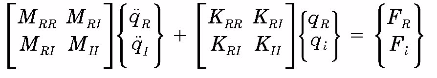 In case of a base excitation the dynamic responses of the structure are a superposition of the rigid body motions with respect to the Rset and the relative motions of Iset, assuming
 ![]() , hence
, hence
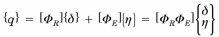 where
where
[R] = matrix of rigid body modes;
[E] = matrix of elastic modes with relative to the Rset (Rset DOFs are constrained);
{} = vector of Rset enforced displacements;
{} = vector of generalized coordinates (Iset).
The matrix of rigid body modes denoted with [R] can be expressed as follows:
 If the Rset DOFs are constrained the following eigenvalue problem can be achieved:
 where
where
![]() = the kth eigenvalue;
= the kth eigenvalue;
{R} = the kth eigenvector associated with ![]() .
.
The matrix of elastic modes [E] is:
 The equation of motions can be expressed in
  :
:
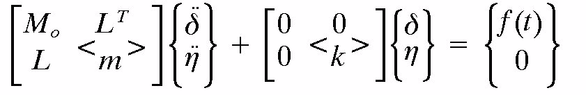 in which the matrix L the matrix of modal participation factors is called. The matrix of modal participation provide a coupling between the motion as a rigid body and the elastic motions.
The modal participation matrix is [L]T = [R]T[M][E].
Introducing for the generalized coordinate k in ad hoc manner modal viscous damping, the equations of motion can be written as follows:
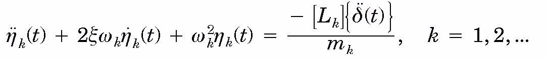 The equation of motion as a rigid body can be written:
 After a Fourier Transformation of the last two equations of motion result in:
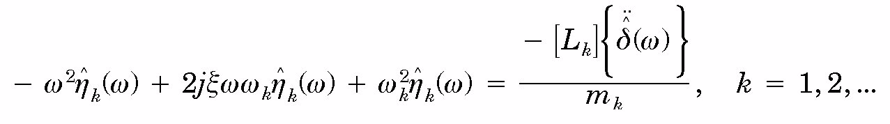 The generalized coordinate is eliminated now and
  will be expressed in
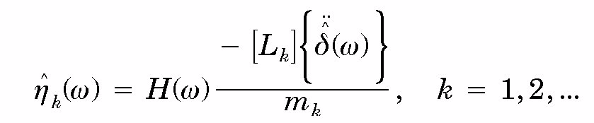 where
where
 Finally it is found:
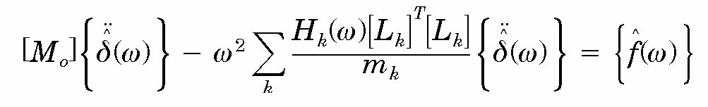 or
or
![]()
![]() is the expression for the modal effective mass:
is the expression for the modal effective mass:
![]() with the generalized mass
with the generalized mass  .
.
It can be proved that ![]() .
.
The six (6) interface DOFs constitute a determined interface. The generalized modal interface (reaction) forces due to elastic vibration modes constrained at the determined interface are:
 or
or
 Another expression for the modal effective mass matrix
 ![]() becomes:
becomes:
![]() One element in the 6 x 6 matrix
One element in the 6 x 6 matrix ![]() ,
, ![]() , becomes:
, becomes:
![]() Equation ,
Equation , ![]()
A more detailed explanation can be found in J.T. Chen, H. K. Hong and C.S. Yeh, Modal Reaction method for modal participation factors in support motion problems, Communications in Numerical Methods in Engineering, Vol 9, 1995.
ANNEX(informative)E-32 discipline documents delivery per review
|
Document Title
|
Phase
|
DRD Ref.
| |||||||||||
|
0
|
A B
|
C
|
D
|
E
| |||||||||
|
MDR
|
PRR
|
SRR
|
PDR
|
CDR
|
QR
|
AR
|
ORR
|
FRR
|
LRR
|
CRR
|
ELR
| ||
|
Computer aided design model description and delivery
|
|
|
|
X
|
X
|
|
|
|
|
|
|
|
ECSS-E-ST-32, Annex A
|
|
Design loads
|
|
|
X
|
X
|
X
|
X
|
|
|
|
|
|
|
ECSS-E-ST-32, Annex B
|
|
Dimensional stability analysis
|
|
|
|
X
|
X
|
X
|
|
|
|
|
|
|
ECSS-E-ST-32, Annex C
|
|
Fatigue analysis
|
|
|
|
|
X
|
X
|
|
|
|
|
|
|
ECSS-E-ST-32, Annex D
|
|
Fracture control analysis
|
|
|
|
|
X
|
X
|
|
|
|
|
|
|
ECSS-E-ST-32, Annex E
|
|
Fracture control plan
|
|
|
|
X
|
X
|
|
|
|
|
|
|
|
ECSS-E-ST-32, Annex F
|
|
Fracture control items lists
|
|
|
|
X
|
X
|
X
|
|
|
|
|
|
|
ECSS-E-ST-32, Annex G
|
|
Material and mechanical part allowables
|
|
|
|
X
|
X
|
|
|
|
|
|
|
|
ECSS-E-ST-32, Annex H
|
|
Mathematical model description and delivery
|
|
|
|
X
|
X
|
X
|
|
|
|
|
|
|
ECSS-E-ST-32, Annex I
|
|
Modal and dynamic response analysis
|
|
|
|
X
|
X
|
X
|
|
|
|
|
|
|
ECSS-E-ST-32, Annex J
|
|
Stress and strength analysis
|
|
|
|
X
|
X
|
X
|
|
|
|
|
|
|
ECSS-E-ST-32, Annex K
|
|
Structure alignment budget
|
|
|
|
X
|
X
|
X
|
|
|
|
|
|
|
ECSS-E-ST-32, Annex L
|
|
Structure buckling
|
|
|
|
X
|
X
|
X
|
|
|
|
|
|
|
ECSS-E-ST-32, Annex M
|
|
Structure mass summary
|
|
|
X
|
X
|
X
|
X
|
|
|
|
|
|
|
ECSS-E-ST-32, Annex N
|
|
Test-analysis correlation
|
|
|
|
|
|
X
|
X
|
|
|
|
|
|
ECSS-E-ST-32, Annex O
|
|
Test evaluation
|
|
|
|
|
|
X
|
X
|
|
|
|
|
|
ECSS-E-ST-32, Annex P
|
|
Test prediction
|
|
|
|
|
X
|
X
|
|
|
|
|
|
|
ECSS-E-ST-32, Annex Q
|
Bibliography
|
ECSS-S-ST-00
|
ECSS system – Description, implementation and general requirements
|
|
ECSS-E-ST-10
|
Space engineering – System engineering general requirements
|
|
ECSS-E-ST-10-02
|
Space engineering – Verification
|
|
ECSS-E-ST-10-03
|
Space engineering – Testing
|
|
ECSS-E-ST-32-03
|
Space engineering – Structural finite element models
|
|
ECSS-E-ST-32-08
|
Space engineering – Materials
|
|
ECSS-E-ST-32-11
|
Space engineering – Modal survey assessment
|
|
ECSS-E-HB-32-20
|
Space engineering – Structural materials handbook
|
|
ECSS-E-HB-32-21
|
Space engineering – Adhesive bonding handbook
|
|
ECSS-E-HB-32-22
|
Space engineering – Insert design handbook
|
|
ECSS-E-HB-32-23
|
Space engineering – Threaded fastener guidelines
|
|
ECSS-E-TM-10-20
|
Space engineering – Product data exchange
|
|
ECSS-E-TM-10-26
|
Space engineering – STEP – TAS, NRF, SPE
|
|
ECSS-M-ST-40
|
Space project management – Configuration and information management
|
|
ECSS-Q-ST-70
|
Space product assurance – Materials, mechanical parts and processes
|