
Space product assurance
Crimping of high-reliability electrical connections
Foreword
This Standard is one of the series of ECSS Standards intended to be applied together for the management, engineering and product assurance in space projects and applications. ECSS is a cooperative effort of the European Space Agency, national space agencies and European industry associations for the purpose of developing and maintaining common standards. Requirements in this Standard are defined in terms of what shall be accomplished, rather than in terms of how to organize and perform the necessary work. This allows existing organizational structures and methods to be applied where they are effective, and for the structures and methods to evolve as necessary without rewriting the standards.
This Standard has been prepared by the ECSS Executive Secretariat, endorsed by the Document and Discipline Focal points, and approved by the ECSS Technical Authority.
Disclaimer
ECSS does not provide any warranty whatsoever, whether expressed, implied, or statutory, including, but not limited to, any warranty of merchantability or fitness for a particular purpose or any warranty that the contents of the item are error-free. In no respect shall ECSS incur any liability for any damages, including, but not limited to, direct, indirect, special, or consequential damages arising out of, resulting from, or in any way connected to the use of this Standard, whether or not based upon warranty, business agreement, tort, or otherwise; whether or not injury was sustained by persons or property or otherwise; and whether or not loss was sustained from, or arose out of, the results of, the item, or any services that may be provided by ECSS.
Published by: ESA Requirements and Standards Division
ESTEC, P.O. Box 299,
2200 AG Noordwijk
The Netherlands
Copyright: 2017 © by the European Space Agency for the members of ECSS
Change log
|
ECSS-Q-70-26A
|
First issue
|
|
ECSS-Q-70-26B
|
Never issued
|
|
ECSS-Q-ST-70-26C
|
Second issue
|
|
ECSS-Q-ST-70-26C Rev.1
|
Second issue, Revision 1
|
|
|
Corrigendum 1 of Second issue Revision 1:
|
Scope
This Standard specifies:
Requirements for the following crimping wire connections intended for high reliability electrical connections for use on spacecraft and associated equipment operating under high vacuum, thermal cycling and launch vibration:
removable contacts, single wire
removable contacts, multiple wires
coaxial contacts, ferrules
lugs and splices.
These are the most commonly used crimping wire connections and are represented in Figure 11.
The general conditions to be met for the approval of connections other than the above mentioned ones.
Additional forms of crimps, not covered in this standard, are listed (not exhaustively) in the informative Annex A.
Product assurance provisions for both the specific and the generic connections mentioned above.
Training and certification requirements for operators and inspectors (clause 5.5.2), additional to those specified in ECSSQST-20.
This standard may be tailored for the specific characteristics and constraints of a space project, in conformance with ECSS-S-ST-00.
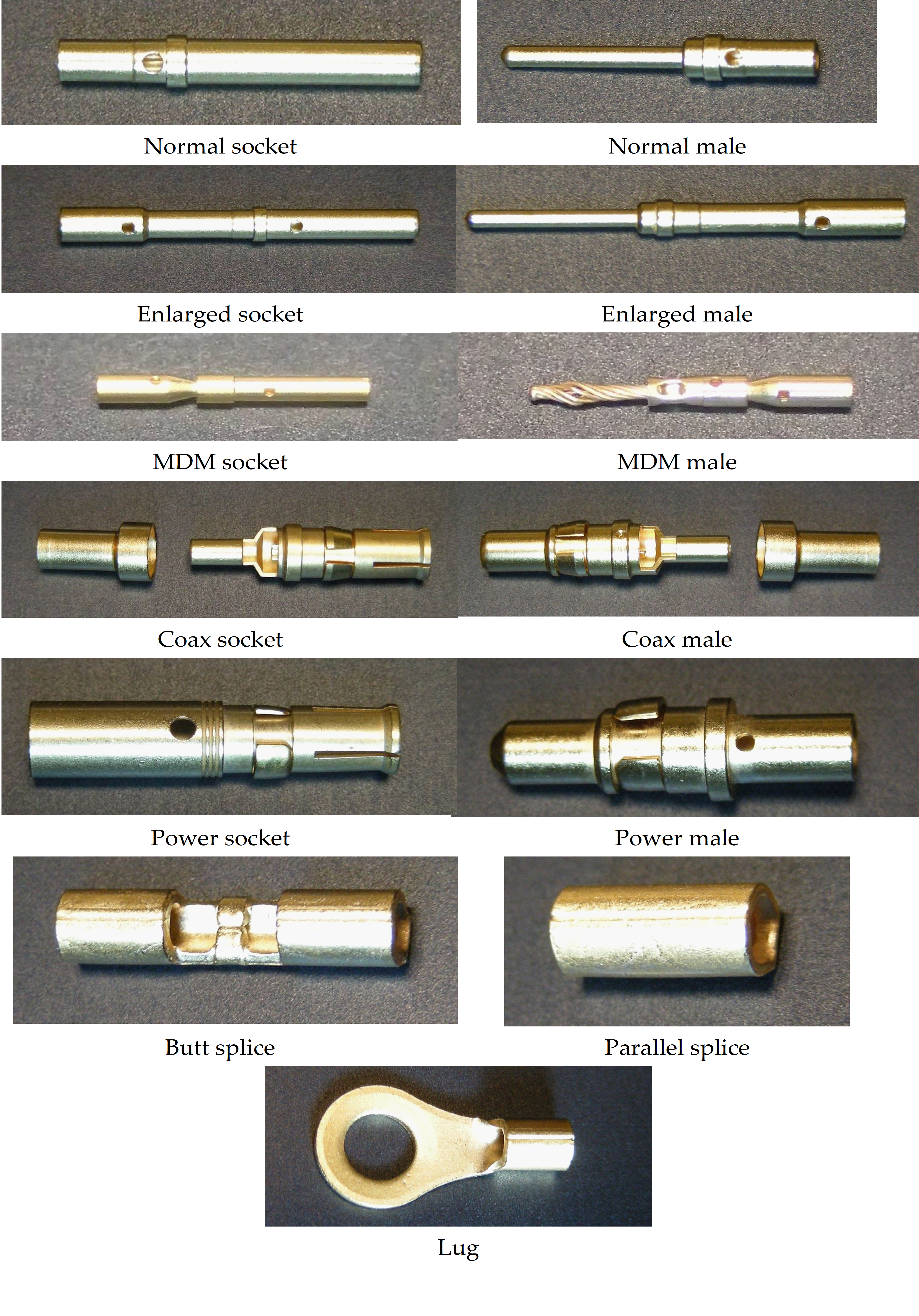 Figure 11: Example of interconnections described in this Standard
Normative references
The following normative documents contain provisions which, through reference in this text, constitute provisions of this ECSS Standard. For dated references, subsequent amendments to, or revisions of any of these publications do not apply. However, parties to agreements based on this ECSS Standard are encouraged to investigate the possibility of applying the most recent editions of the normative documents indicated below. For undated references the latest edition of the publication referred to applies.
|
ECSSS-ST-00-01
|
ECSS system - Glossary of terms
|
|
ECSSQST-1009
|
Space product assurance - Nonconformance control system
|
|
ECSSQST-20
|
Space product assurance - Quality assurance
|
|
ECSSQST-60
|
Space product assurance - Electrical, electronic and electromechanical (EEE) components
|
|
ECSS-Q-ST-60-05
|
Space product assurance – General requirements for hybrids
|
|
ECSSQST-70
|
Space product assurance - Materials, mechanical parts and processes
|
|
ECSSQST-7008
|
Space product assurance - Manual soldering of high-reliability electrical connections
|
|
ECSS-Q-ST-70-38
|
Space product assurance - High-reliability soldering for surface-mount and mixed technology
|
|
ECSSQST-7071
|
Space product assurance - Data for selection of space materials and processes
|
|
SAE-AS-22520, 24 October 2011
|
Crimping tools, , wire termination, General specification for
|
|
SAEAS7928B10 March 2011
|
Terminals, lugs, splices, conductor, crimp style, copper, general specification for
|
|
ISO 7500-1:2004
|
Metallic materials - Verification of static uniaxial testing machines - Part 1: tension/compression testing machines - Verification and calibration of the force-measuring system
|
|
ESCC 3901, Issue 2 May 2013
|
ESCC generic specification No. 3901 Wires and cables, electrical, 600V, low frequency
|
Terms, definitions and abbreviated terms
Terms defined in other standards
For the purpose of this Standard, the terms and definitions from ECSSSST0001 apply, in particular for the following terms:
acceptance
analysis
batch
component
conformance
contaminant
For the purpose of this Standard, the terms and definitions from ECSS-Q-ST-60-05 apply, in particular for the following terms:
process identification document (PID)
For the purpose of this Standard, the terms and definitions from ECSS-Q-ST-70-08 apply, in particular for the following terms:
electrical connection
Terms specific to the present standard
adjustable indenter tool
crimping ratcheting tool which has an adjustable part (setting variable) that indents or compresses the conductor barrel or ferrule
crimping configuration
combination of crimping tool, crimp item and number and type of wires defined by the procurement specification
- 1 Example of crimp item include lug, splice and contact, ferrule.
- 2 Type of wires include material, size, finish and batch if not ESCC qualified wire.
- 3 Crimping tool based on the combination of tool reference, setting and locator (when necessary).
crimping tool
mechanical ratcheting tool used for permanently attaching a wire connection device to a conductor by pressure deformation or by reshaping the barrel around the conductor to establish good electrical and mechanical contact
ferrule
short metal tube used to make crimp connections to the outer conductor of shielded or coaxial cables
intrinsic wire strength
tensile strength of a wire used in a crimped assembly, determined by a specific pull test
lug
metallic tube with drilled flange projection for fixing to a connection point
splice
metallic tube for joining two or more conductors to each other
terminal
metallic device that is used to make an electrical connection
Abbreviated terms
For the purpose of this Standard, the abbreviated terms from ECSS-S-ST-00-01 and the following apply:
|
Abbreviation
|
Meaning
|
|
AWG
|
American wire gauge
|
|
DRD
|
document requirement definition
|
|
IPA
|
iso-propyl alcohol
|
|
KIP
|
key inspection point
|
|
MIP
|
mandatory inspection point
|
|
NCR
|
nonconformance report
|
|
PID
|
process identification document
|
|
QA
|
quality assurance
|
|
RFA
|
request for approval
|
|
RFW
|
request for waiver
|
|
RH
|
relative humidity
|
Nomenclature
The following nomenclature applies throughout this document:
The word “shall” is used in this Standard to express requirements. All the requirements are expressed with the word “shall”.
The word “should” is used in this Standard to express recommendations. All the recommendations are expressed with the word �“should”.
It is expected that, during tailoring, recommendations in this document are either converted into requirements or tailored out.
The words “may” and “need not” are used in this Standard to express positive and negative permissions, respectively. All the positive permissions are expressed with the word “may”. All the negative permissions are expressed with the words “need not”.
The word “can” is used in this Standard to express capabilities or possibilities, and therefore, if not accompanied by one of the previous words, it implies descriptive text.
In ECSS “may” and “can” have completely different meanings: “may” is normative (permission), and “can” is descriptive.
The present and past tenses are used in this Standard to express statements of fact, and therefore they imply descriptive text.
Principles
This Standard is structured such that the necessary level of quality is achieved, consistently maintained and high reliability of the end product assured. The following principles are covered:
Preparatory conditions to determine the availability of facilities, tools and equipment, along with obligatory hazard and health precautions.
Specific interconnections, as identified in the Scope above, are then covered in detail including
Material selection,
Process identification and documentation.
New crimp combinations beyond those identified in the Scope.
Test methods and acceptance criteria for both specific and generic types of interconnections are specified.
Quality assurance measures for both the operator and the inspector are prescribed:
Training and certification of personnel,
Calibration of tools and equipment,
Workmanship standards and acceptance criteria,
Inspection criteria and sequence,
Records from material incoming inspection through delivery of the end product, including KIP, MIP, travellers, follow-up sheets, log books, traceability samples and the handling of deviations by RFA or NCR.
It is important to perform the work taking into account health and safety regulations, and in particular the national standards on this subject.
Requirements
Preparatory conditions
Facilities
Overview
The requirements in this clause can generally be met by using cleanrooms. It is not, however, mandatory to use a cleanroom.
Depending on supplier and customer business agreement.
Facility cleanliness
The supplier shall provide cleaning services for production facilities where high reliability crimping is performed.
Production facilities where high reliability crimping is performed shall be maintained in a clean and tidy condition.
Loose material that can cause contamination of the crimped connection shall be removed.
For example: Dirt, dust, oils and cut wire strands.
Furniture shall be kept to a minimum in the work areas and be arranged to allow easy and thorough cleaning of the floor.
Working surfaces shall be covered with an easily cleaned hard top, antistatic mat or have a replaceable surface of clean, non-contaminating silicone-free paper.
Environmental conditions
The crimping area shall have a controlled environment, which limits entry of contamination.
The area shall be continuously controlled as follows:
- room temperature: (22 ± 3) °C;
- relative humidity: (55 ± 10) %.
The workstations shall not be exposed to draughts.
Fresh air shall be supplied to the room through a filtering system with positive pressure difference with regard to adjacent rooms.
The exhaust air shall be suitably restricted.
Lighting requirements
The supplier shall ensure adequate illumination conditions of the crimp workstations.
The minimum light intensity shall be 1 080 lux on the work surface.
A minimum of 90 % of the work area shall be shadow-less and without severe reflections.
Tools and equipment
Crimping tools
The supplier shall provide the tooling necessary for continued high quality crimping.
Examples of crimping tools are shown in Figure 51.
Tools used shall employ an integral ratcheting mechanism, which controls the crimping operation in conformance to SAE-AS-22520.
The mechanism ensures that, once the operation is started, the tool cannot be opened until the crimping cycle is complete.
Tools shall be sealed on one setting value in case of variable settings tools.
Tool calibration shall be verified in conformance with the clause 5.5.6 requirements.
Proper operation of the integral ratcheting mechanism or the positive stops on pneumatic tools shall be verified as defined in clause 5.5.6.
Before starting a crimping process on a new terminal size and wire type, the tool used for crimping of the previous wire type shall be returned to the tool storage.
If the tool settings seals are found removed or broken, the tool shall be removed from the work place and returned immediately for recalibration.
Tools used in the crimping operation shall be clean and excess lubricant removed before crimping starts.
Tools shall be individually labelled.
This identification is recorded in the manufacturing connector follow up sheet.
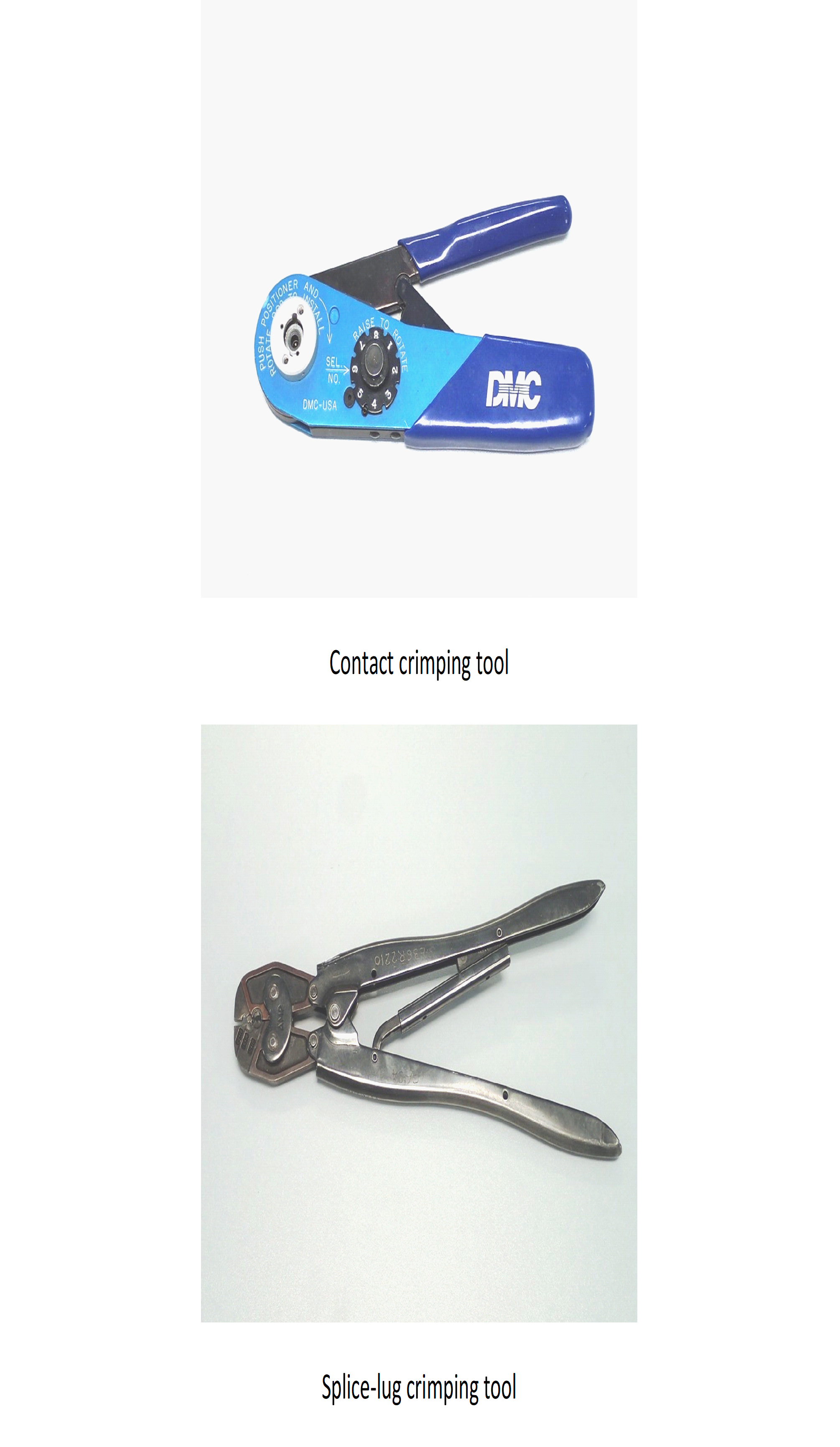 Figure 51: Example of crimping tools
Insulation strippers
The supplier shall provide the tooling necessary to avoid damage to the conductor.
The selection of thermal or precision cutting devices, manual or automatic power-driven, shall ensure integrity of the conductor strands.
Wire stretching by use of mechanical strippers shall be avoided.
The conductor shall not be twisted, ringed, nicked, cut or scored by stripping operation.
Both thermal and mechanical stripping tools shall be calibrated periodically on sample evaluation during a production run.
For coated wires the exposure of underlined base metal shall be a cause for rejection.
Cutting pliers
The supplier shall provide the tooling necessary for precision wire trimming and cutting.
The cutter used for trimming conductor wire shall shear sharply and consistently to produce a clean, flat, smooth-cut surface along the entire cut edge.
Twisting action during cutting operation shall be avoided.
<<deleted>>
The cutting edges shall be regularly checked for damage and maintained in a sharp condition.
Test and monitoring equipment
The supplier shall provide the equipment specified in Table 51 necessary for verification activities specified in clause 5.4.3.
Table 51: Equipment for verification process
|
Performance tests activity
|
Equipment characteristic
|
|
<<deleted>>
|
<<deleted>>
|
|
Tensile strength (in conformance with clause 5.4.3 requirements)
|
Tensile testing machine conforming to ISO 7500 class 1 or better. Axial load applied at a rate of (20 – 40) mm/min ±2 mm/min
|
|
Visual inspection
|
Magnification 7 to 40
|
|
Monitoring requirements of the process
|
|
|
Temperature
|
15 C to 30 C, accurate to 1 C
|
|
Relative humidity (RH)
|
40 % to 70 %, accurate to 1 %
|
Crimping operations for different types of interconnections
General
The supplier shall visually examine wires, terminals and connector contacts for cleanliness, absence of oil films and freedom from tarnish or corrosion before assembly.
The supplier shall perform cleaning of the work pieces using IPA.
Further cleaning or other treatment shall not be carried out except the case when validation and qualification of a cleaning product was performed on all used materials.
The supplier shall handle work pieces with clean lint free gloves or finger cots.
Before a crimping activity, tools at the operator’s station shall be verified to conform to those selected in accordance with the applicable PID or procedures.
All conductor strands shall be inserted cleanly into the barrel without any buckling.
Strands shall not be left outside or cut back to reduce the conductor diameter to fit an undersized barrel.
The supplier shall use tools as specified in SAE-AS-22520 for the crimp contact configuration.
Examples of crimping parameters are given in Table A-1 to Table A-6
The supplier shall take provisions to avoid degradation of the silver plated wire caused by tarnish during storage.
<<deleted>>
The crimping of single solid wires shall not be used.
Material selection
The supplier shall use silver plated copper multi stranded wire and braided shield cable procured in conformance with the requirements from ESCC generic specification 3901.
In cases where other types of wire and wire finishes are used a request for approval (RFA) in conformance with DRD from Annex D from ECSS-Q-ST-70 shall be provided to the customer for approval.
Examples of wire and wire finishes needing RFA include nickel- or fused tin-plated wires, stainless steel, phosphor bronze, copper, constantan, and nickel alloys.
The supplier shall use high strength copper alloy wire for 24 AWG, 26 AWG and 28 AWG crimped joints.
Soft or annealed copper wire are not acceptable for crimped joints of 24 AWG, 26 AWG and 28 AWG size.
The supplier shall use space-qualified components having gold plated finishes in conformance with ECSSQST-60.
Specific items such as ferrules, splices, contacts and lugs shall be purchased to SAE-AS7928 specification.
When gold plating is not available the finish shall be in conformance with ECSSQST-7071.
Ferrules, splice, contacts and lugs supporting an external nickel layer can be used in case there is no alternative finish, although tool wear is accelerated.
Cadmium, chromate-coated cadmium, tin-lead and non-fused tin-plating shall not be used.
Tin-lead finish is not acceptable for crimp connection due to creep.
Process review and documentation
The supplier shall perform a review of all the materials, tools and techniques planned to be used to ensure conformance to requirements of this standard and as a means of identifying potential problems.
Type of wire includes base material, number of strands, plating metal, type and thickness of insulation.
Dies, setting of controls for the length of strip in automatic stripping machines and the selection of specific locators or positioners for crimping tools, shall be selected to meet process requirements.
The requirement is valid for power driven and manual crimping processes as well as for size and tolerance for crimping tools.
The results of the review shall be documented in a specific internal procedure.
Contact barrel and single wire crimping
The supplier shall give preference to the selection of single multistranded wire interconnections.
The supplier shall not use strands of wire doubled backed to increase the conductor diameter.
The supplier shall use a specific contact to be compatible with the cross-sectional area of the wire.
Examples of a specific contact include reduced, normal or enlarged barrel.
For 28 AWG up to 16 AWG wire sizes, the insulation clearance shall be maintained between 0,3 mm and 1,0 mm.
For wire size bigger than 16 AWG the insulation clearance shall be maintained between 0,3 mm and 2 mm.
On D-sub contacts, a transparent shrink fit insulation sleeve shall be applied over the rear of the contact and the wire insulation both to cover the insulation clearance and to prevent any risk of a short circuit.
Examples of crimping parameters are given in Table A-1. An example of a typical contact barrel and an example of single wire crimping is shown in Figure 52.
Multistranded type of wire shall be used in case the filler wire is used to increase the conductors diameter.
The use of potting, to ensure insulation at the rear of connectors with removable contacts, shall not be used except when authorized by the customer through RFA.
The use of potting on these types of connectors can violate specification from manufacturer and can invalidate the qualification status of the connector itself.
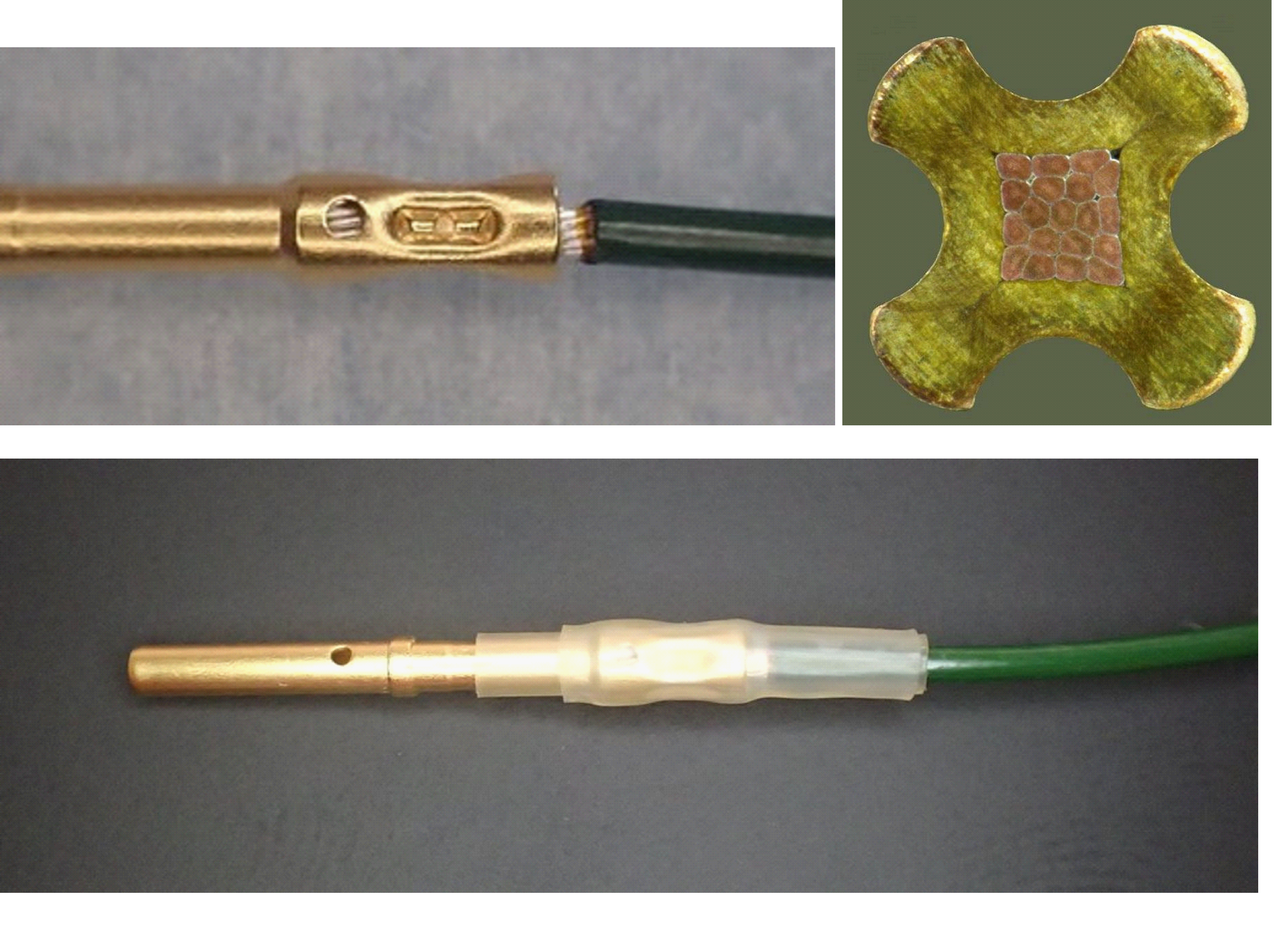 Figure 52: Example of a typical connector barrel and single wire crimping
Contact barrel and multiple wire crimping
Requirements of this clause shall be applied when single multistranded wire crimping cannot be used.
The maximum number of wires in one crimp barrel shall be two.
The sum of the two nominal conductor sections shall be compatible with the crimp barrel used
Both conductors shall be of the same material and support the same plating finish.
- 1 For example: both are silver plated and not a combination of silver and nickel plated, both are high-strength copper alloy and not a combination of pure copper and high-strength copper alloy.
- 2 Strand wires or conductors can be inserted straight into the barrel or twisted together to obtain a “single” conductor.
Axial strength measurements shall be performed in compliance with requirements in clause 5.4.3.2.
Examples of crimping parameters are given in Table A-2 and an example of a typical contact barrel and multi-wire crimping is shown in Figure 53.
For separate conductors introduced straight into the barrel the following shall apply:
- the actual strength measurement is performed on one of the wires (the smaller, if two different sizes are used);
- the axial strength requirement is determined as specified in requirements of clause 5.4.3.2 for the actual size of wire pulled, assuming a barrel size equal to that wire’s gauge.
Examples of crimping parameters are given in Table A-3 and an example of a typical connector barrel and multi-wire crimping is shown in Figure 53.
The conductor diameter shall not be increased by the use of individual strands of wire or double back wire.
Multistranded type of wire shall be used in case the filler wire is used to increase the conductors diameter.
For 28 AWG up to 16 AWG wire sizes the maximum insulation clearance shall be maintained between 0,3 mm and 1,0 mm.
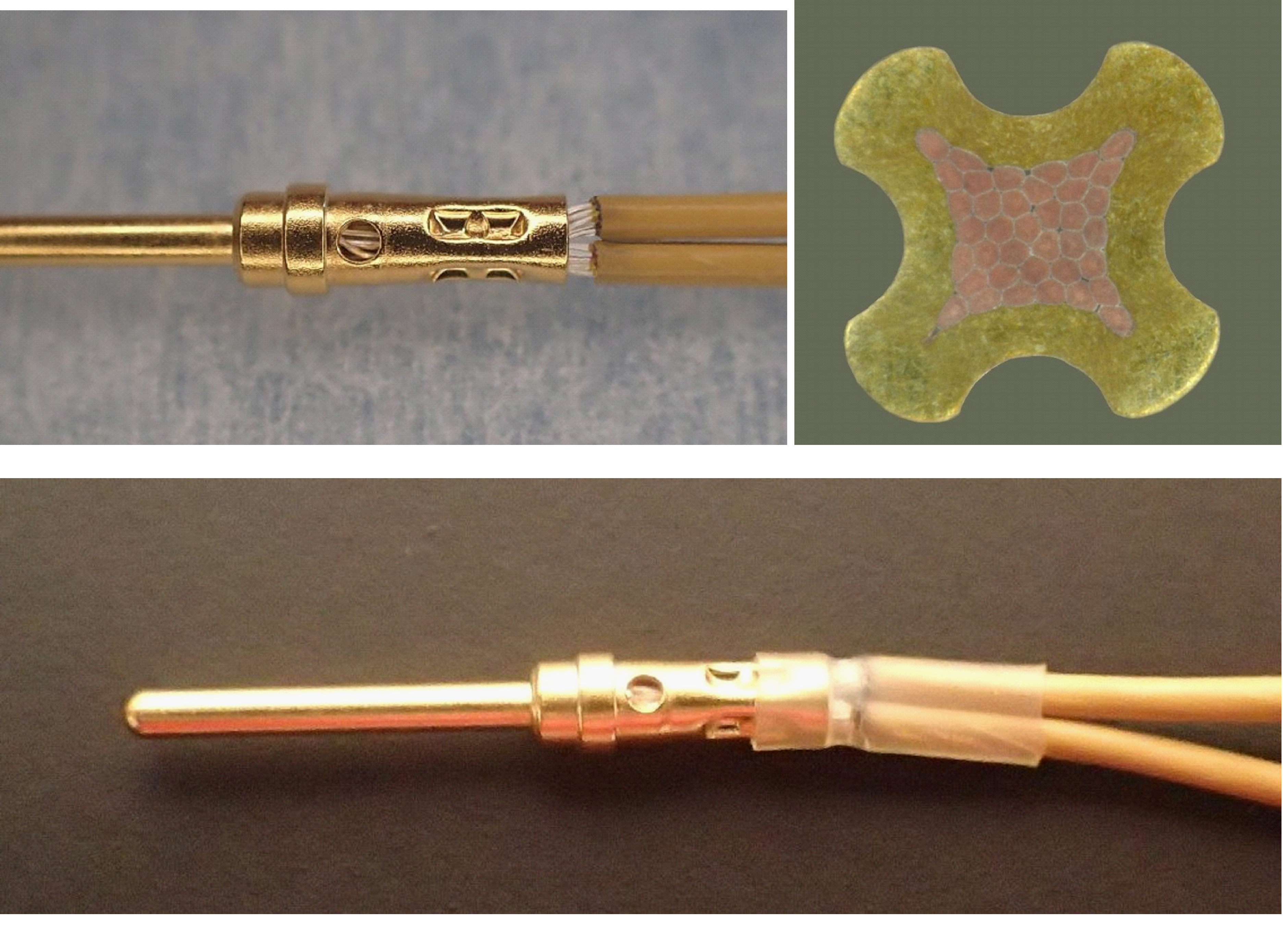 Figure 53: Example of a typical connector barrel and multi-wire crimping
Ferrule shield crimping
The shielding on coaxial cables shall be ensured by braided strands.
Axial strength measurements shall be performed in compliance with requirements from clause 5.4.3.3.
<<deleted, moved to 5.2.6f>>
Only one braided shield shall be crimped in one ferrule connection.
The braid end shall only be located at the ferrule crimp level in order to prevent any risk of short circuit between central pin and braid strands.
Following crimping, the assembly shall be protected by shrink tubing.
Examples of crimping parameters are given in Table A-6 and an example of a typical ferrule shield crimping is shown in Figure 54.
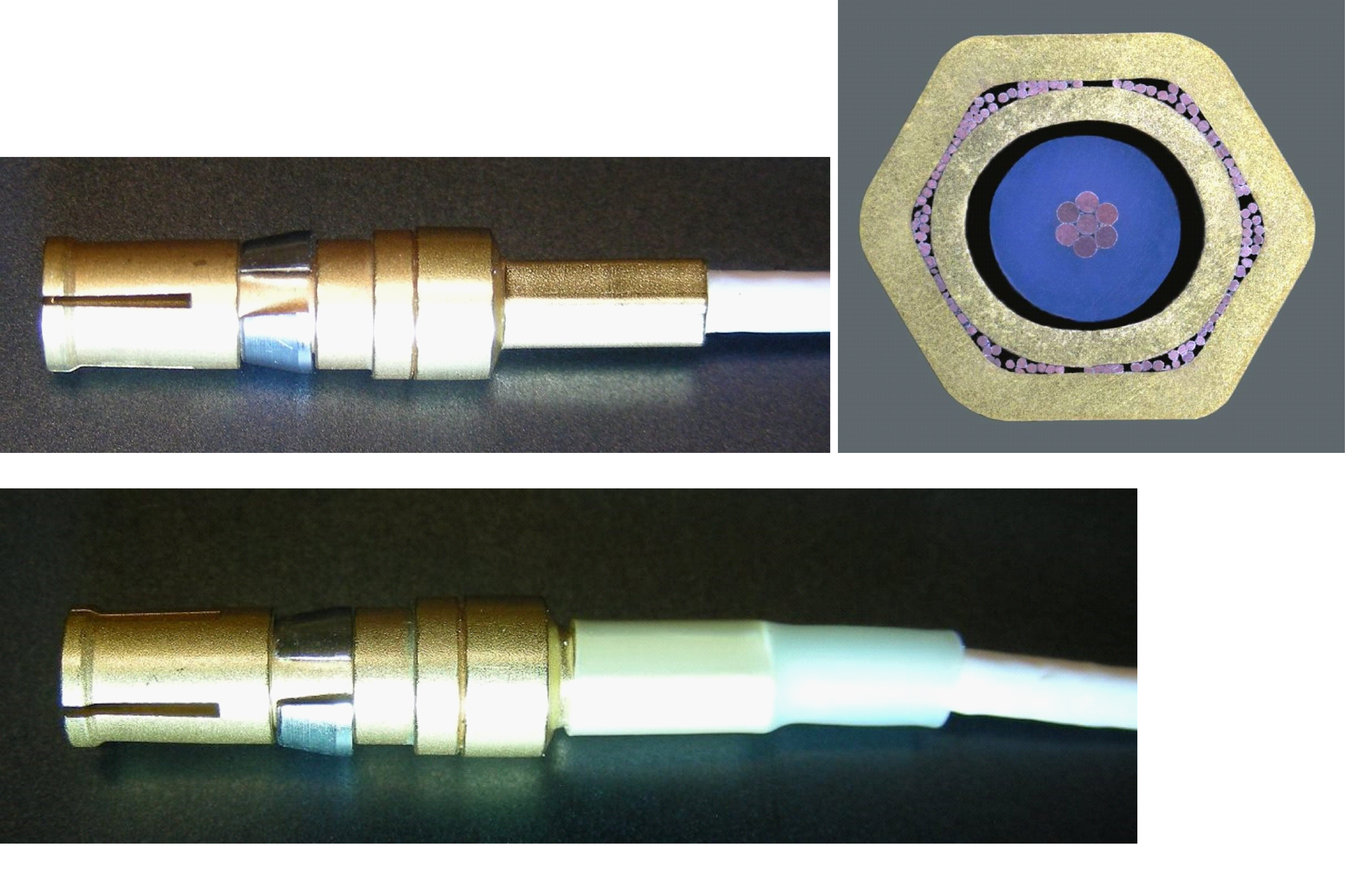 Figure 54: Example of a typical ferrule shield crimping
Lug and splice wire crimping
Only tools specified by the manufacturer of the terminals shall be used.
The maximum number of wires shall be ten on the same assembly.
Seven wires maximum shall be on the same side.
All conductors shall be of the same material and within a size range of 4 wire gauges including odd and even AWG sizes on the same side.
If the number of conductors on the same side is more than two all conductors shall be positioned parallel in the terminal barrel before crimping.
Axial strength measurements shall be performed in compliance with requirements from clause 5.4.3.3.
<<deleted>>
Figure A-6
Following crimping, the assembly shall be protected by shrink tubing.
Examples of typical lug and splice wire crimpings are shown in Figure 55 and Figure 56.
In case the number of conductors on the same side is limited to two then the conductors may be twisted together to form a single conductor.
For 28 AWG up to 16 AWG wire sizes the maximum insulation clearance shall be maintained between 0,3 mm and 1,0 mm.
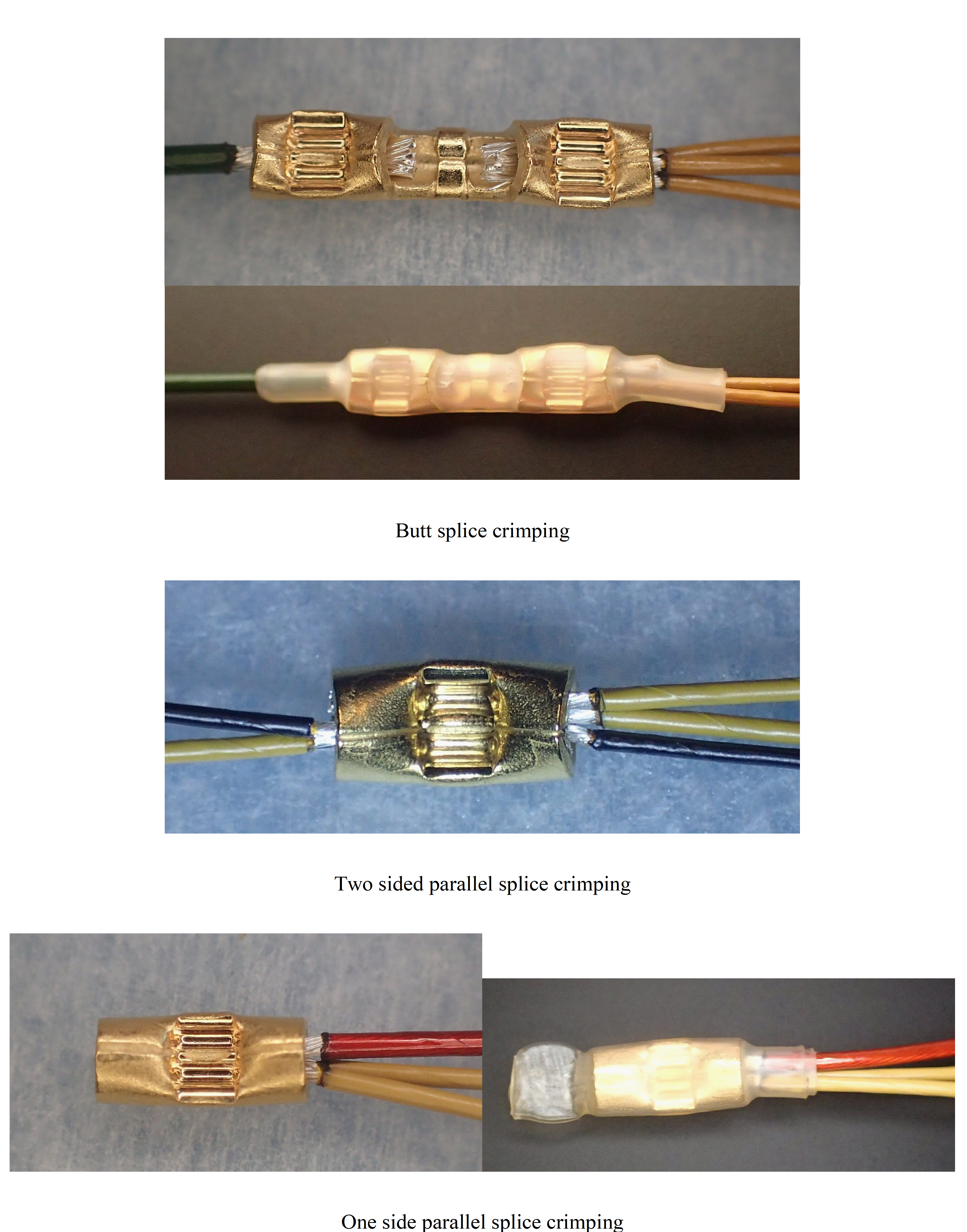 Figure 55: Examples of typical lug and splice wire crimping (1 of 2)
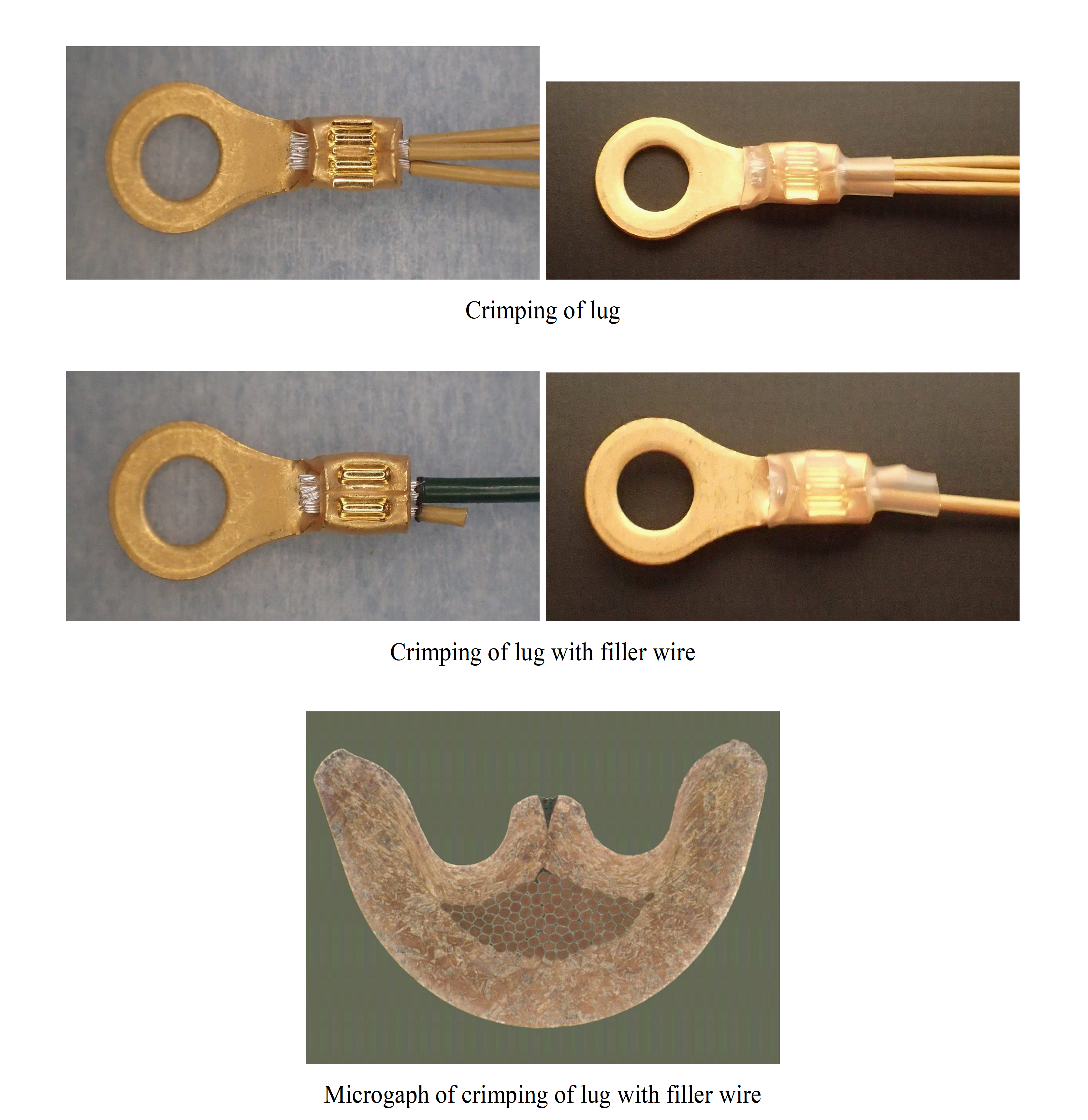 Figure 56: Examples of typical lug and splice wire crimping (2 of 2)
Requirements for crimp configuration qualification
General
All crimp configurations shall be qualified in compliance with requirements from clause 5.3.2.
The supplier shall document the data of successful process qualification in a specific internal procedure to ensure continued high quality of production performance.
<<deleted>>
Any change to an element of the qualified crimp configuration specified in requirement 5.3.1a shall be qualified.
The supplier shall ensure that the selected materials are qualified for the mission environment.
In case the mission environment exceeds the temperature range for which the materials are qualified, a qualification shall be performed and agreed with the customer
Examples of materials include cables and crimp items.
In case qualification is needed, the supplier shall issue an RFA.
Qualification process test procedure
The supplier shall perform tensile strength tests on samples prepared at a number of tool settings, in conformance with the requirements specified in clause 5.4 and in conformance with the following process:
- Ten samples prepared at the point specified by the crimping tool manufacturer as a starting point for calibrating tools.
- For connector contacts the tool indenter opening is then adjusted in convenient increments above and below this point, and ten samples pulled at each increment.
- For lugs, splices and ferrules, ten samples are prepared at each setting of the crimping tool and pulled.
- A plot is made with increments being close enough together to obtain a smooth curve.
- The maximum in tensile strength is then determined and evaluated.
- The optimum tool setting lies approximately in the middle of the flat top portion of the tensile-strength plot.
- In case of very close average tensile strength values, the microsectioning of the samples relevant to the concerned settings is performed to identify the best setting.
Typical settings of crimping tool are given in Annex A.2.
The supplier shall validate satisfactory results achieved from the final tool setting at the operating point on a minimum of ten samples in conformance with the methods defined in clause 5.4 and according to the following process:
- Tensile strength tests are performed on five samples corresponding to the operating point.
- <<deleted>>
- Metallographic tests are performed on a minimum of three samples corresponding to the operating point.
- Not tested samples are retained for reference.
Test data shall be recorded in a qualification report.
The qualification report shall include the results of the search for the optimum tool setting specified in requirement 5.3.2a.
Figure 57 presents a flow chart of the Qualification process test procedure of clause 5.3.2.
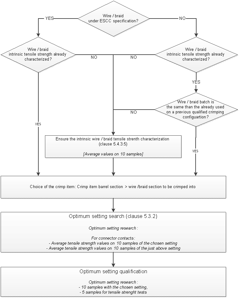 Figure 57: Qualification process test procedure flow chart
Sealing and marking
The supplier shall seal and mark calibrated tools in conformance with clause 5.5.6.3 requirements.
Batch to batch variation
Wires qualified by ESCC
For wires qualified by ESCC the qualified tool set-up may be used without additional validation when different batches of wires are used.
Wires not qualified by ESCC
For wires not qualified by ESCC the qualified optimum set-up shall be confirmed for each new batch of wire in conformance with the following qualification process:
- tensile strength tests are performed on five samples corresponding to the operating point,
- a further five samples are produced at tool settings above and below the operating point and tensile tested.
The average tensile strength at the operating point, as per 5.3.4.2a.1, shall be higher or equal to the result obtained in 5.3.4.2a.2 and in compliance with 5.4.3.
In case the average result at the operating point is lower than the result obtained in 5.3.4.2a.2 the qualification process specified in the requirements from clause 5.3.2 shall be repeated.
Test methods
General
The supplier shall submit samples to the tests specified in clauses 5.4.3 and 5.4.4.
The number of samples is dependent on the specific process requirement (in conformance with clauses 5.3.2 ,5.3.4, 5.5.5 and 5.5.6.2 requirements).
Test samples shall meet the requirements of clause 5.5.4.1.
Records of all results shall be tabulated in conformance with 5.5.7.
<<deleted>>
<<deleted>>
<<deleted>>
<<deleted>>
Tensile strength
General
The supplier shall use a tensile testing device with characteristics in conformance with Table 51.
The connections shall be loaded until failure occurs.
The value at failure shall be recorded, together with the information as to whether the failure was “pull-out”, “break in crimp” or “break in wire”.
The required ultimate axial strengths for compactive and dispersive crimped joints shall be determined as specified in clauses 5.4.3.2 and 5.4.3.3.
A typical test fixture for testing ferrule lug, splice and contact crimps is shown in Figure A-6.
The clamping of the free bare ends of wire or metallic braided shield directly in the clamping fixtures of the tensile machine shall not be used.
Contact barrel wire crimping
The required axial strength of the crimped assembly shall be 75 % of the intrinsic wire strength as specified in clause 5.4.3.5.
Examples of typical values of intrinsic wire strength of ESCC qualified wires and the 75% requirement are detailed in Table B-1.
<<deleted>>
In case of two crimped wires the axial strength the measurement shall be performed on one of the two inserted wires and be at least 75 % of the intrinsic strength of the wire.
If two different wire gauges are used then the test specified in 5.4.3.2c shall be performed on the smaller of the two.
Only one tensile test per sample is performed and the test shall be continued until failure occurs.
Ferrule
The required axial strength of the crimped assembly shall be 75 % of the intrinsic wire or braid strength as specified in clause 5.4.3.5.
Axial strength measurements shall be performed only on the shield after removal of the core dielectric.
Lug and splice
The required axial strength of the crimped assembly shall be 75 % of the intrinsic wire or braid strength as specified in clause 5.4.3.5.
In the case of several equal wire sizes crimped into the same barrel axial strength measurements shall be performed on only one wire per sample.
In the case of different wire sizes crimped into the same barrel axial strength measurements shall be performed on only one wire per sample from the smallest gauge
In the case where opposed wires are tested a specifically designed test fixture shall be used.
A typical test fixture is shown in Figure A-6
Only one tensile test per sample is performed and the test shall be continued until failure occurs.
Characterisation of intrinsic wire / braid strength
Intrinsic strength of wire or metallic braided shields shall be determined as follows:
- A minimum of ten samples of 200 mm length from the wire batch to be used for the crimped assembly are prepared for testing by first stripping the insulation from both ends of the wire,
- For metallic braided shield axial strength measurements are performed only on the shield after removal of the core dielectric,
- To avoid wire or metallic braided shield strands damage in the clamping area, suitable end tabs, such as soldered splice are used,
- The samples are tested to failure at a rate of (20 – 50) mm/min,
- The maximum load achieved is recorded,
- In case of failure in the clamps the result is discarded,
- Intrinsic wire strength is calculated by averaging a minimum of ten valid tests.
The intrinsic wire strength characterization shall be performed once for each batch of wire.
For ESCC wires, the intrinsic wire strength characterization value obtained on a batch of wire to other batches of the same type and size of wire from the same manufacturer, may be applied.
Metallography
The supplier shall employ a certified laboratory to perform the metallographic tests specified in the requirements 5.4.4c to 5.4.4i.
The customer shall approve the certification status of the laboratory.
The joint to be sectioned shall be mounted in a low exotherm resin capable of being moulded without the application of external pressure.
The joint shall be oriented that the wire is perpendicular to the polishing surface.
The specimen shall be ground with the aid of appropriate grades of silicon carbide papers, in order to expose the mid-section of the joint.
This section shall then be polished with successively finer grades of diamond paste down to 1 µm.
To aid microscopic examination, the polished section shall be very lightly etched with an accepted chemical reagent specific to the composition of the materials being crimped.
The section shall be examined in both as-polished and etched states using a metallographic microscope at a magnification up to 400.
The following acceptance criteria shall be met:
- Each micro section is free from contamination;
- The crimp barrel is evenly deformed;
- Voids occupy less than 10 % of the cross sectioned area of the wire volume;
- The wires and barrel appear as a gas-tight joint and conform to the workmanship sample prepared during qualification;
- All strands are deformed from their circular cross section;
- There are no indentations or fracturing of the deformed receptacle barrel or its plated finish.
- For ferrule shield crimping the requirements of 5.4.4i.3. and 5. are not applicable.
The laboratory for the metallographic tests should be certified with ISO 17025.
Quality assurance
General
The supplier shall install a Quality Assurance (QA) function in conformance with the requirements as defined in ECSS-QST-20.
The quality control process shall be as specified in Figure 58.
Personnel training and certification
Training program
The supplier shall employ trained and certified personnel for all stripping and crimping operations implementing and maintaining a skill matrix.
The supplier shall develop, maintain and implement a training programme, in conformance with ECSS-Q-ST-20.
The aim of the training programme is to provide for excellence of workmanship and personnel skills, careful and safe operations, and improvement of the quality of crimped joints.
Certification
<<deleted>>
The certification of personnel shall be based upon objective evidence of crimp quality, resulting from test and inspection of the crimped joints.
Operators or inspectors shall be re-certified in cases of repeatedly unacceptable quality levels and changes in crimping techniques, parameters or required skills.
The supplier shall perform training and certification at a school authorized by the customer.
Certification shall be valid for a period of two years.
Documentation
The supplier shall maintain records of the training and certification status of crimping operators and inspection personnel.
Figure 58: Quality control during crimping operation
Workmanship
The supplier shall prepare standards consisting of satisfactory work samples (in conformance with the Figure 59 and Figure 510)
The supplier shall have readily available visual aids, which clearly illustrate the quality characteristics of all crimped connections utilized.
Defects such as those listed in clause 5.5.4.2 and shown in Figure 59 shall be included as examples.
The operator shall discard production crimps which are defective.
Defective test samples shall not be discarded.
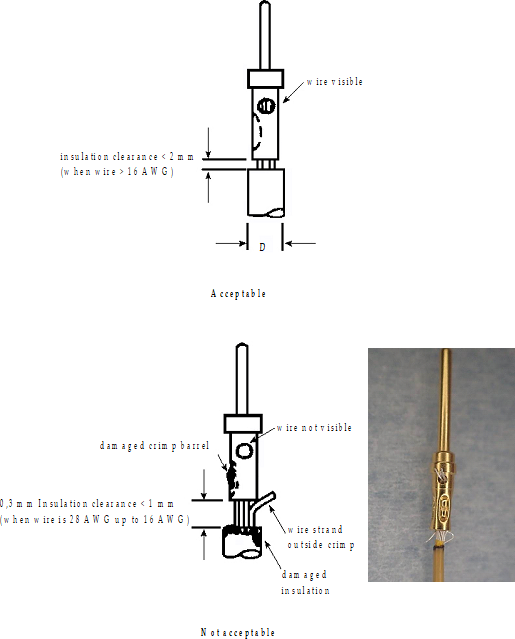 Figure 59: Visible workmanship standards
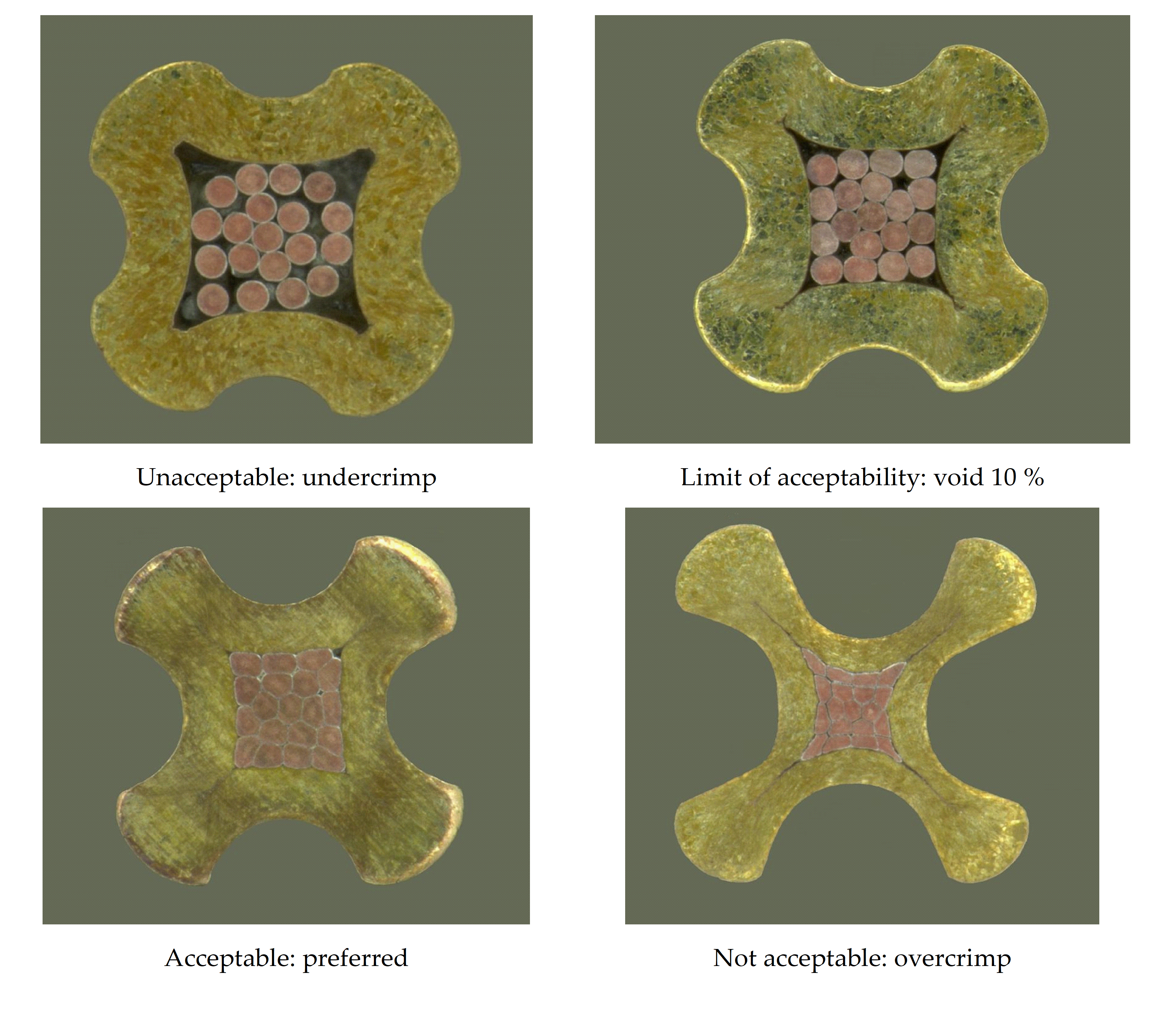 Figure 510: Workmanship examples and crimp micro-sections
Visual inspection
Pre-crimp inspection (performed by the operator)
The wire shall be examined for no evidence of nicks, rings, broken strands, untwisted lay or not-removed insulation in the area of the crimp before the stripped wire is inserted into the crimped item barrel.
Damaged wires where the base material is exposed shall not be used.
Contacts and terminal barrels that show evidence of the presence of tarnish, corrosion or physical damage, including bent contacts, shall not be used.
Inspection shall check that the combination of wire size and type and crimp item are in accordance with the drawing or control document.
Post-crimp inspection (performed by quality assurance)
The QA inspector shall carry out inspection with the use of a binocular microscope having a minimum linear magnification of 7.
Further examination of surface characteristics can be performed at higher magnifications.
The inspector shall not physically disturb parts and conductor leads to help inspection.
The following acceptance criteria shall be met;
- Wire insulation is not damaged by the crimping operation;
- The conductor is visible in the inspection hole when an inspection hole is provided; in the case of lugs and splices the free end of the conductor is visible at the exit point;
- The crimp barrel has no unintentional sharp edges, peeled metal, burrs, cracked platings or cuts after crimping;
- All functional parts, including all retention clips or locking devices, are operational after the crimp has been made;
- No tarnished or corroded crimped item are present;
- No misplaced crimps, as determined by marks found on areas not designed to take crimping, are present
- No undercrimps or overcrimps are present;
- The detection of an under crimp or over crimp shall cause the stop of manufacturing as follows:
- operations at that work place ,
- rejection of all production crimps made since the last verification or pull test,
- investigation of tools, wire and crimp item to determine the cause of failure.
- No bent contacts are present.
- Wire strands are not damaged as a result of the crimping operation.
- The insulation clearance complies with the requirements 5.2.4d and 5.2.4e. Failure to meet the acceptance criteria of 5.5.4.2c shall be cause for rejection.
General
100 % visual inspection shall be performed by independent inspector.
The independent inspector should be from Quality Assurance.
Pre-crimp inspection may be performed by an operator who has successfully followed and passed an internal training scheme which has been implemented by QA as specified in 5.5.2.
Shift performance inspection and test for harness manufacturing
<<deleted>>
<<deleted>>
<<deleted>>
<<deleted>>
<<deleted>>
<<deleted>>
<<deleted>>
<<deleted>>
<<deleted>>
<<deleted>>
Prior to the start of a new harness manufacturing the following shall be done:
- The tool settings are determined for each crimp combinations, wire and crimp item, that are planned to be used during the project,
- Crimping tools are dedicated to one crimping combination, wire and contact, and have individual identification,
- Crimping tools are validated at start of manufacture and traceability noted in its correspondent log book,
- Crimp configuration settings are locked on each contact crimping tool.
- 1 Ideally, crimping tools are dedicated to one project.
- 2 Shift performance test for crimping operation with small number of crimps as integration and repairs, are detailed in clause 5.5.9.
At the start of harness manufacturing the following shall be done: - Four samples of each of the different configurations are produced at the optimum setting for connector and ferrules,
- Four samples of the configuration with the minimum number of wires into the barrel and four samples of the configuration with maximum number of wires for lugs and splices,
- Three of the samples of each type from the four samples specified in the requirements 5.5.5l.1 and 5.5.5l.2 are pull tested,
- The fourth sample is retained as traceability witness,
- All results are recorded in the dedicated project logbook. Intermediate tool inspections of a harness manufacturing shall be done as follows:
- At the start of each new shift cleanliness control of the active part of the tool and “go/no-go” checks are performed,
- Crimping tools which are used for less than 500 crimps per week shall be revalidated after each 500 crimp operations or 2 months whichever is earlier in conformance with requirements from the clause 5.5.6.2
- The results are recorded in the dedicated tool logbook in accordance with 5.5.6.2c. For manufacturing runs of more than 500 crimps per week with the same crimping tool the following shall be done:
- Cleanliness control of the active part of the tool and “go/no-go” checks are performed,
- Tensile test on not less than four samples each 500 crimp operations are performed,
- Revalidation of the tools is performed each 1500 crimp operations or 2 months, whichever is earlier in conformance with requirements from the clause 5.5.6.2,
- The results are recorded in the dedicated tool logbook in accordance with 5.5.6.2c. At the end of the harness manufacturing the following shall be done:
- Four samples of each of the different configurations are produced at the optimum setting for connector contacts and ferrules,
- Four samples of the configuration with the minimum number of wires into the barrel and four samples of the configuration with maximum number of wires for lugs and splices,
- Three samples from four samples specified in the requirements 5.5.5o.1 and 5.5.5o.2 are pull tested,
- The fourth sample is retained as traceability witness,
- All results are recorded in the dedicated project logbook.
Calibration of crimping tools
General
The QA organization of the supplier shall ensure that each crimping tool and measuring equipment is calibrated as indicated in the subsequent sub clauses.
The QA organization of the supplier shall record any suspected and actual equipment failure as a project nonconformance report
Based on past nonconformance reports previous results can be examined to ascertain whether or not re-inspection or retesting is required.
The QA organization of the supplier shall notify the customer of the nonconformance details.
The supplier’s calibration procedure shall include the requirements specified in this clause for tool calibration.
Validation
The QA organization of the supplier shall ensure that crimping tools, both manual and powered, are calibrated when initially set up for each specific wire size, connection size and type prior to first use.
Calibration shall be verified in conformance with the following check-list:
- cleanliness control of the active part of the tool (e.g. indenters);
- set up with the aid of the “go/no-go” gauge in conformance with specified conditions;
- tests in conformance with the clause 5.4 requirements on not less than four samples.
After satisfactory verification of calibration the tool status shall be documented in a “tool calibration sheet” to ensure tool traceability.
This traceability shall be established by periodic analysis of the corresponding data from the performance inspection and tests (in conformance with clause 5.5.5 requirements),
A significant drift in test results shall result in tool rejection.
Such a tool is generally labelled "out-of-calibration tool" (in conformance with clause 5.5.6.4 requirements).
Sealing and marking
The supplier shall provide sealing for calibrated crimping tools to ensure against unauthorized alteration of adjustment settings.
A wire and lead seal method shall be used if the tool has provisions for it;
In case requirement 5.5.6.3b cannot be implemented, the tool shall be sealed by a non-reusable decal seal, which, if the calibrated setting is altered, is visibly damaged.
Seals shall be placed on all external adjustment points of the tool.
Out-of-calibration tools
Tools that are out of calibration shall be returned to the tool facility for readjustment and calibration.
Tools that are worn or damaged shall be identified as rejected and removed from the fabrication area.
Records
The supplier shall maintain traceability throughout the process from incoming inspection to final test, including details of test equipment, tools and personnel employed in performing the task.
Quality records and logbooks shall be retained for at least ten years
Quality records and logbooks shall contain the following information:
- the as-built and test configuration list (waiver and deviation summary);
- nonconformance reports and corrective actions;
- copy of the visual inspection and performance test results with reference to the relevant procedure, personnel and tools used;
- records of the training, testing and certification status of crimping operators in conformance with clause 5.5.3 requirements.
Nonconformance
The QA organization of the supplier shall disposition any nonconformance which is observed in respect of the process in conformance with the quality assurance requirements, in conformance with ECSSQST-1009.
Failure of a crimping tool to pass any requirement specified in clause 5.1.2.1 shall require rejection of all crimps made by that tool since it was last tested successfully for acceptance.
Special crimping activities at spacecraft level, modifications and repairs
Crimping tools shall have individual identification.
Crimping tools shall be validated every 12 months or every 1500 crimps whichever is earlier in compliance with requirements from clause 5.5.6.2.
Results of validation specified in the requirement 5.5.9b shall be recorded in its dedicated logbook.
The supplier shall keep a logbook for each tool.
The logbook shall show the quantity of parts crimped since each calibration and since each “go/no-go” operation.
The in-process controls shall be in compliance with requirements 5.5.9g or 5.5.9h.
After every 250 crimping operations four samples shall be crimped of which:
- three samples are submitted to the tensile strength test as specified in the requirements from the clause 5.4.3,
- the fourth sample is retained for reference and traceability purposes in conformance with requirements from clause 5.5.6.2, and
- a “go/no-go” check of the tool is performed at the beginning of each shift and recorded in the logbook. In case the supplier does not maintain a logbook of the crimping operation, detailed in 5.5.9g, the following shall be performed by each operator:
- prepare four samples at the beginning of a shift or before a series of crimping operations of which:
- three samples are submitted to the tensile strength test as specified in the requirements from the clause 5.4.3, and
- the fourth sample is retained for reference and traceability purposes in conformance with requirements from clause 5.5.6.2.
- at the end of the shift or after 250 crimping operations, whichever is reached first, four samples are crimped of which:
- three samples are submitted to the tensile strength test as specified in the requirements from the clause 5.4.3, and
- the fourth sample is retained for reference and traceability purposes in conformance with requirements from clause 5.5.6.2.
A crimping tool shall be changed whenever a wire size or contact size is changed.
After a change of a crimping tool, as specified in the requirement 5.5.9i, the operator shall, unless the tool has a current validation, prepare four samples at the start of the operation, of which:
- three samples are submitted to the tensile strength test as specified in the requirements from the clause 5.4.3, and
- the fourth sample is retained for reference and traceability purposes in conformance with requirements from clause 5.5.6.2. The supplier shall perform an analysis of shift performance test results, in comparison with initial tool calibration results, to determine any drift in tool performance.
Figure 511 illustrates the shift performance test flow.
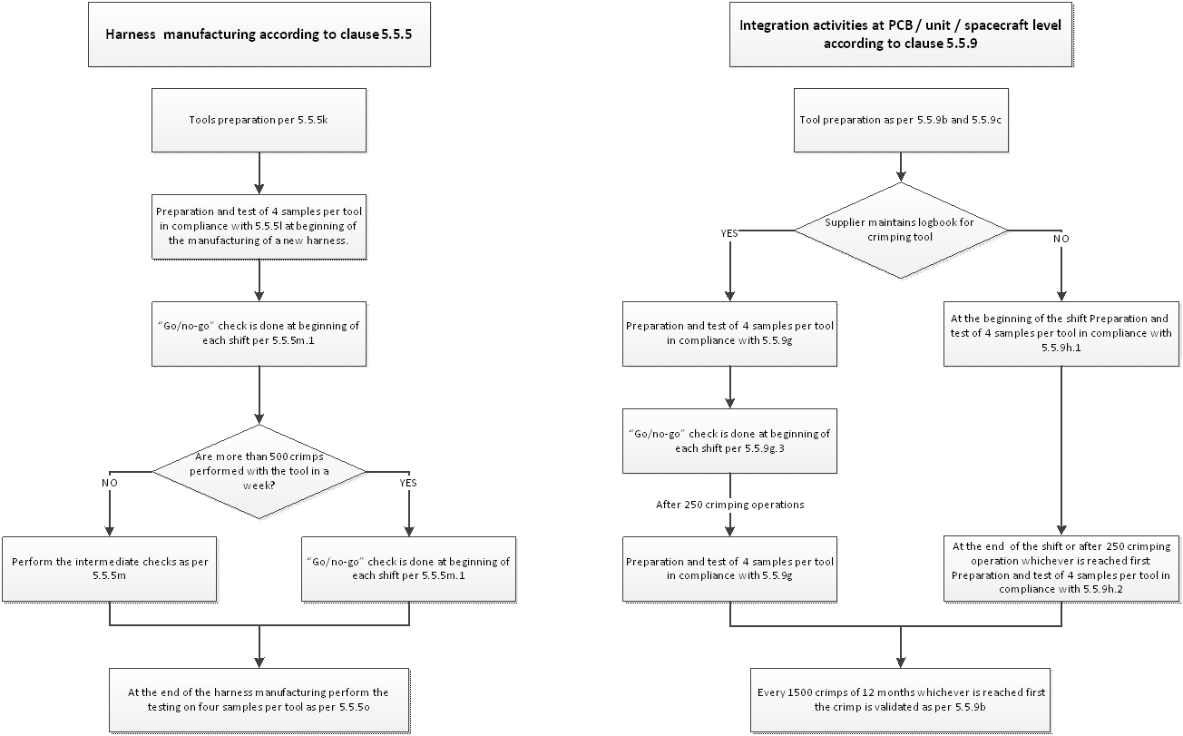 Figure 511: Shift performance test flowchart
Document requirements
The supplier shall produce documentation for:
- Process identification, in a PID or a specific internal procedure and RFA,
- Inspection,
- Traceability,
- Testing, both procedures and records,
- Logbooks, and
- Calibration. The format of the documents shall be in accordance with the deliverables item list defined in the business agreement.
No specific DRD requirements emerge from this Standard.
ANNEX(informative)Crimp configurations and tools
Overview of crimp configurations
Many crimp interconnection technologies are currently available for space applications. Confined or compactive crimps are made by a tool, which exerts an even pressure around the receptacle barrel circumference such that even deformation is applied on all sides; the only means of stress relief is by elongation of the barrel and wire. Typical settings for the crimping tool are given in A.2.
Non-confined or dispersive crimps result from compression of the receptacle barrel with an indenter die having one or two indents or, alternatively, by two or four radially opposed indenter dies (in conformance with Figure A-4 and Figure A-5).
The achievement of an acceptable crimped joint is controlled by the tools and materials used, but workmanship - the manner in which they are employed - is also important. Items that constitute workmanship are those under the control of the operator. They include careful butting of the wire against the stop in the stripping operation to ensure correct insulation gap, loading of a connector pin in the positioner to the full distance, inserting the stripped wire into the connector pin barrel or terminal until it shows in the inspection hole or through the contact in the case of crimp lugs and re-twisting the strands not more than the natural lay, if disturbed during the stripping operation.
 Figure: Confined irregular-octagon crimp (compactive)
 Figure: Dimpled confined octagon crimp (compactive)
 Figure: Regular-hexagon crimp (compactive)
 Figure: Semicircular one- or two-indent crimp (dispersive)
 Figure: Four-indent crimp (dispersive)
Typical settings of crimping tools
For the type of crimping covered in this Standard typical tool selector settings are applicable. Those are, however, only indicative and require effective calibration or validation before use for production of high-reliability crimps, in conformance with clause 5.5.6
Tables for the different types of crimp configuration are shown below. They include reference to the tooling and selector settings by wire and barrel sizes.
For the specific case of lug and splice configurations where opposed wires are tested (in conformance with clause 5.4.3 requirements) a typical test fixture is shown in Figure A-6.
Table: Guideline for selector setting - Four-indent crimp (dispersive) - Single wire
|
Connector
|
Wire gauge (AWG)
|
Wire barrel contact size
|
Crimping tool / Selector setting
| ||
|
M22520/2-01
|
M22520/1/01
|
M300-BT
| |||
|
D * SUB 3401-002 connector family
|
8
|
8 - 8
|
-
|
-
|
6
|
|
10
|
8 - 10
|
-
|
-
|
5
| |
|
12
|
8 - 14/12
|
-
|
-
|
2
| |
|
16
|
20 - 18
|
7
|
-
|
|
|
|
18
|
20 - 18
|
6
|
-
|
-
| |
|
|
|
|
-
|
-
| |
|
20
|
20 - 20
|
7
|
-
|
-
| |
|
22
|
20 - 20
|
6
|
-
|
-
| |
|
24
|
20 - 20
|
5
|
-
|
-
| |
|
26
|
20 - 26
|
6
|
-
|
-
| |
|
28
|
20 - 26
|
6
|
-
|
-
| |
|
22
|
22 - 22
|
4
|
-
|
-
| |
|
24
|
22 - 22
|
3
|
-
|
-
| |
|
26
|
22 – 22
|
2
|
-
|
-
| |
|
28
|
22 – 22
|
1
|
-
|
-
| |
|
MIL-C 38999 3401-044;3401-052 and 3401-056 connector family
|
12
|
12 - 12
|
-
|
8
|
-
|
|
14
|
12 - 12
|
-
|
-
|
-
| |
|
16
|
12 - 12
|
-
|
7
|
-
| |
|
16
|
16 - 16
|
-
|
6
|
-
| |
|
18
|
16 - 16
|
-
|
5
|
-
| |
|
20
|
16 - 16
|
-
|
4
|
-
| |
|
20
|
20 - 20
|
7
|
3
|
-
| |
|
22
|
20 - 20
|
6
|
2
|
-
| |
|
24
|
20 - 20
|
5
|
1
|
-
| |
|
22
|
22 - 22
|
4
|
-
|
-
| |
|
24
|
22 - 22
|
3
|
-
|
-
| |
|
26
|
22 - 22
|
2
|
-
|
-
| |
|
28
|
22 - 22
|
1
|
-
|
-
| |
|
DBAS 3401-008 connector family
|
12
|
12 - 12
|
-
|
8
|
-
|
|
14
|
12 - 12
|
-
|
7
|
-
| |
|
16
|
16 - 16
|
-
|
6
|
-
| |
|
18
|
16 - 16
|
-
|
5
|
-
| |
|
20
|
16 - 16
|
|
4
|
-
| |
|
20
|
20 - 20
|
7
|
-
|
-
| |
|
22
|
20 - 20
|
6
|
-
|
-
| |
|
24
|
20 - 20
|
5
|
-
|
-
| |
|
26
|
20 - 26
|
6
|
-
|
-
| |
|
28
|
20 - 26
|
5
|
-
|
-
| |
|
HE801 3401-016 connector family
|
22
|
22 - 22
|
5
|
|
|
|
24
|
22 - 22
|
4
|
|
|
|
|
26
|
22 - 22
|
4
|
|
|
|
Table: Guideline for selector setting - Four-indent crimp (dispersive) - Two wires
|
Connector
|
Wire gauge (AWG)
|
Wire barrel contact size
|
Crimping tool / Selector setting
| ||
|
M22520/2-01
|
M22520/1/01
|
M300-BT
| |||
|
D*SUB
|
|
|
|
|
|
|
12 + 12
|
8 - 8
|
-
|
-
|
6
| |
|
-
|
8 - 10
|
-
|
-
|
-
| |
|
16 + 16
|
8 - 14/12
|
-
|
-
|
3
| |
|
20 + 20
|
20 - 18
|
7
|
-
|
-
| |
|
22 + 22
|
20 - 18
|
6
|
-
|
-
| |
|
24 + 24
|
20 - 20
|
6
|
-
|
-
| |
|
26 + 26
|
20 - 20
|
5
|
-
|
-
| |
|
28 + 28
|
20 - 20
|
4
|
-
|
-
| |
|
DBAS 3401-008 connector family
|
-
|
12 - 12
|
-
|
-
|
-
|
|
20 + 20
|
16 - 16
|
-
|
6
|
-
| |
|
24 + 24
|
20 -20
|
6
|
-
|
-
| |
|
26 + 26
|
20 - 20
|
5
|
-
|
-
| |
|
28 + 28
|
20 - 20
|
4
|
-
|
-
| |
Table: Guideline for selector setting – Four-indent crimp (dispersive) – Two different wires
|
Connector
|
Wire gauge (AWG)
|
Wire barrel contact size
|
Crimping tool / Selector setting
| ||
|
M22520/2-01
|
M22520/1/01
|
M300-BT
| |||
|
D*SUB
|
-
|
8 - 8
|
-
|
-
|
-
|
|
12 + 16
|
8 - 10
|
-
|
-
|
5
| |
|
-
|
8 – 14/12
|
-
|
-
|
-
| |
|
20 + 22
|
20 - 18
|
6
|
-
|
-
| |
|
22 + 24
|
20 - 20
|
8
|
-
|
-
| |
|
22 + 26
|
20 - 20
|
7
|
-
|
-
| |
|
24 + 26
|
20 - 20
|
6
|
-
|
-
| |
|
26 + 28
|
20 - 20
|
4
|
-
|
-
| |
|
26 + 28
|
22 - 22
|
4
|
|
|
|
|
DBAS 3401-008 connector family
|
-
|
12 - 12
|
-
|
-
|
-
|
|
-
|
16 - 16
|
-
|
-
|
-
| |
|
26 + 28
|
20 -20
|
5
|
-
|
-
| |
Table: Guideline for selector setting – Four-indent crimp (dispersive) – Single wire
|
Connector
|
Wire gauge (AWG)
|
Wire barrel contact size
|
Crimping tool / Selector setting
|
|
M22520/2-01
| |||
|
MDMA
|
24
|
24 – 24
|
3
|
|
26
|
24 – 26
|
2
| |
|
28
|
24 - 26
|
2
|
Table: Guideline for selector setting – Four-indent crimp (dispersive) – Two identical wires
|
Connector
|
Wire gauge (AWG)
|
Wire barrel contact size
|
Crimping tool / Selector setting
|
|
M22520/2-01
| |||
|
MDMA
|
28 + 28
|
24 -24
|
3
|
Table: Guideline for die selection – Regular hexagon (compactive ) – Ferrule coaxial shield crimp
|
Coaxial sort
|
Coaxial cable reference
|
M22520/5-01 Crimping tool Die / Slot selection
|
M22520/10-01 Crimping tool Die / Slot selection
| ||
|
D*SUB
|
RG 178 BU
|
M22520/5-03
|
B
|
M22520/10-05
|
B
|
|
RG 196 AU
|
M22520/5-03
|
B
|
M22520/10-05
|
B
| |
|
RGL-196 #28
|
M22520/5-03
|
B
|
M22520/10-05
|
B
| |
|
50 CIS
|
M22520/5-03
|
A
|
M22520/10-05
|
A
| |
|
50 CIS BLG
|
M22520/5-03
|
A
|
M22520/10-05
|
A
| |
|
SMA
|
50 CIS
|
M22520/5-03
|
A
|
M22520/10-05
|
A
|
|
50 CIS BLG
|
M22520/5-03
|
A
|
M22520/10-05
|
A
| |
|
50 CIS DTR
|
M22520/5-03
|
A
|
M22520/10-05
|
A
| |
Typical test fixture for pull tests
For the specific case of lug and splice configurations where opposed wires are tested, see clause 5.4.3, a typical test fixture is shown in Figure A-6.
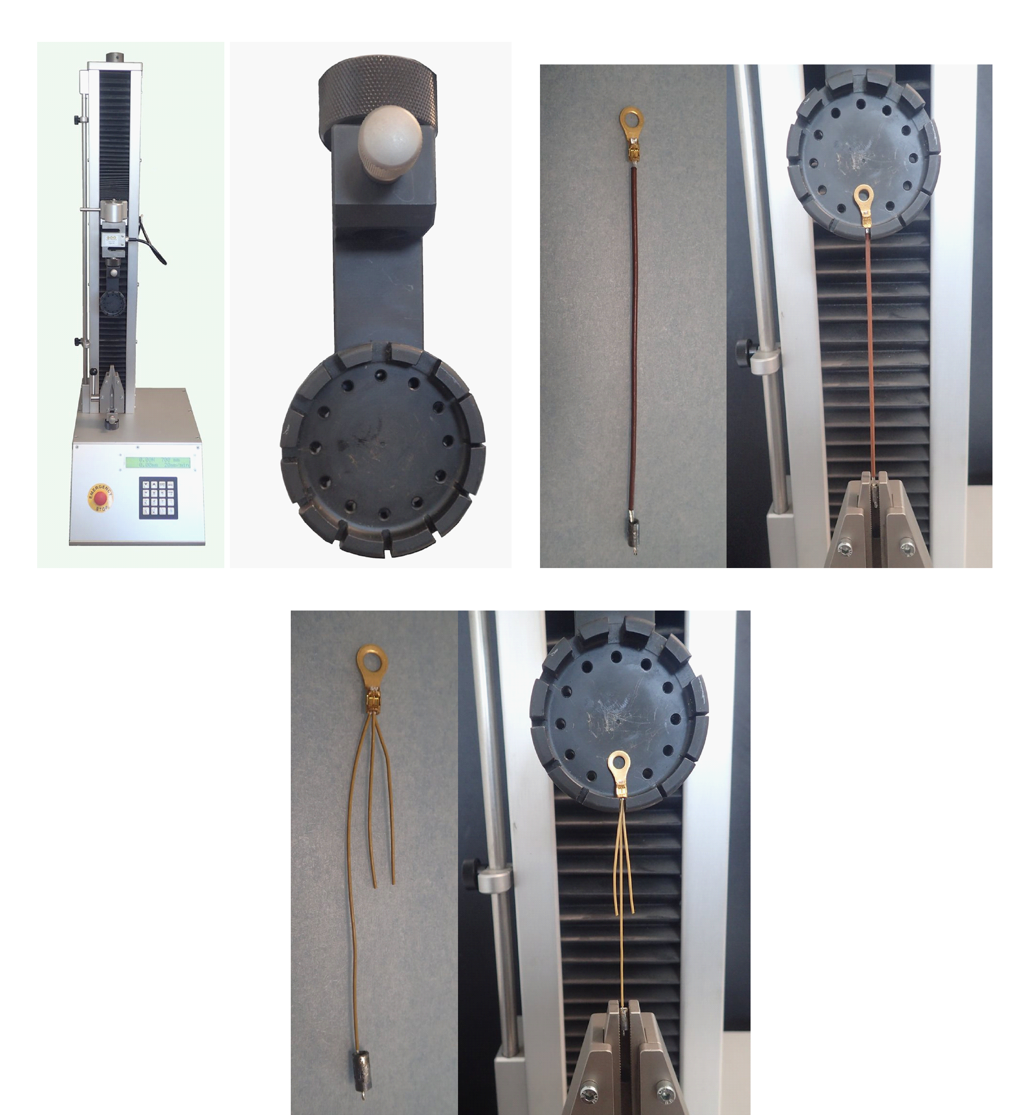 Figure: Typical test fixture for testing lug and splice crimps
ANNEX(informative)Examples of typical ultimate axial strength
Examples of typical values of intrinsic wire strength of ESCC qualified wires and presented in the Table B-1.
Table: Typical ultimate axial strength for compactive and dispersive crimped joints manufactured using qualified ESCC wires
|
AWG
|
Number and size of strands ( in mm)
|
Conductor section in mm2
|
Minimum tensile resistance for crimps with the following composition
| |||
|
Kapton
|
Tefzel
|
Teflon/Kapton
|
Silver-plated pure copper
|
Silver-plated copper alloy
| ||
|
3901/001-002
|
3901/012
|
3901/019
| ||||
|
28
|
19 x 0,08
|
7 x 0,12
|
7 x 0,127
|
0,095
|
-
|
35 N
|
|
26
|
19 x 0,10
|
19 x 0,10
|
19 x 0,10
|
0,15
|
-
|
45 N
|
|
24
|
19 x 0,12
|
19 x 0,12
|
19 x 0,12
|
0,22
|
-
|
60 N
|
|
22
|
19 x 0,16
|
19 x 0,15
|
19 x 0,15
|
0,38
|
65 N
|
-
|
|
20
|
19 x 0,20
|
19 x 0,20
|
19 x 0,20
|
0,6
|
110 N
|
-
|
|
18
|
19 x 0,25
|
19 x 0,25
|
-
|
0,93
|
170 N
|
-
|
|
16
|
19 x 0,30
|
19 x 0,30
|
19 x 0,30
|
1,34
|
250 N
|
-
|
|
14
|
27 x 0,30
|
37 x 0,25
|
-
|
1,91
|
330 N
|
-
|
|
12
|
45 x 0,30
|
37 x 0,32
|
37 x 0,32
|
3,18
|
550 N
|
-
|
|
10
|
-
|
-
|
-
|
5,30
|
850 N
|
-
|
|
8
|
-
|
-
|
-
|
8,98
|
1500 N
|
-
|
|
6
|
-
|
-
|
-
|
13,4
|
2300 N
|
-
|
|
4
|
-
|
-
|
-
|
21,8
|
3750 N
|
-
|
|
2
|
-
|
-
|
-
|
33,5
|
-
|
-
|
|
1
|
-
|
-
|
-
|
41,8
|
-
|
-
|
|
0
|
-
|
-
|
-
|
53
|
-
|
-
|
Bibliography
|
ECSS-S-ST-00
|
ECSS system — Description and implementation and general requirements
|