
Space engineering
SpaceWire - Remote memory access protocol
Foreword
This Standard is one of the series of ECSS Standards intended to be applied together for the management, engineering and product assurance in space projects and applications. ECSS is a cooperative effort of the European Space Agency, national space agencies and European industry associations for the purpose of developing and maintaining common standards. Requirements in this Standard are defined in terms of what shall be accomplished, rather than in terms of how to organize and perform the necessary work. This allows existing organizational structures and methods to be applied where they are effective, and for the structures and methods to evolve as necessary without rewriting the standards.
This Standard has been prepared by the ECSS-E-ST-50-52 Working Group, reviewed by the ECSS Executive Secretariat and approved by the ECSS Technical Authority.
Disclaimer
ECSS does not provide any warranty whatsoever, whether expressed, implied, or statutory, including, but not limited to, any warranty of merchantability or fitness for a particular purpose or any warranty that the contents of the item are error-free. In no respect shall ECSS incur any liability for any damages, including, but not limited to, direct, indirect, special, or consequential damages arising out of, resulting from, or in any way connected to the use of this Standard, whether or not based upon warranty, contract, tort, or otherwise; whether or not injury was sustained by persons or property or otherwise; and whether or not loss was sustained from, or arose out of, the results of, the item, or any services that may be provided by ECSS.
Published by: ESA Requirements and Standards Division
ESTEC, ,
2200 AG Noordwijk
The
Copyright: 2010 © by the European Space Agency for the members of ECSS
Change log
|
ECSS-E-ST-50-52A
|
Never issued
|
|
ECSS-E-ST-50-52B
|
Never issued
|
|
ECSS-E-ST-50-52C
|
First issue
|
Scope
There is a number of communication protocols that can be used in conjunction with the SpaceWire Standard (ECSS-E-ST-50-12), to provide a comprehensive set of services for onboard user applications. To distinguish between the various protocols a protocol identifier is used, as specified in ECSS-E-ST-50-51.
This Standard specifies the Remote Memory Access protocol (RMAP), which is one of these protocols that works over SpaceWire.
The aim of RMAP is to support reading from and writing to memory in a remote SpaceWire node. RMAP can be used to configure a SpaceWire network, control SpaceWire nodes, and to transfer data to and from SpaceWire nodes. RMAP is specified in this Standard.
This standard may be tailored for the specific characteristic and constrains of a space project in conformance with ECSS-S-ST-00.
Normative references
The following normative documents contain provisions which, through reference in this text, constitute provisions of this ECSS Standard. For dated references, subsequent amendments to, or revision of any of these publications do not apply. However, parties to agreements based on this ECSS Standard are encouraged to investigate the possibility of applying the more recent editions of the normative documents indicated below. For undated references, the latest edition of the publication referred to applies.
|
ECSS-S-ST-00-01
|
ECSS system - Glossary of terms
|
|
ECSS-E-ST-50-12
|
Space engineering - SpaceWire - Links, nodes, routers and networks
|
|
ECSS-E-ST-50-51
|
Space engineering - SpaceWire protocol identification
|
Terms, definitions and abbreviated terms
Terms defined in other standards
For the purpose of this Standard, the terms and definitions from ECSS-S-ST-00-01 and ECSS-E-ST-50-51 apply.
Terms specific to the present standard
None.
Abbreviated terms
The following abbreviations are defined and used within this standard:
|
Abbreviation
|
Meaning
|
|
CRC
|
cyclic redundancy code
|
|
EEP
|
error end of packet
|
|
EOP
|
end of packet
|
|
FCT
|
flow control token
|
|
FIFO
|
first in first out
|
|
ID
|
identifier
|
|
inc
|
increment
|
|
Len
|
length
|
|
LS
|
least-significant
|
|
LSB
|
least-significant bit
|
|
MS
|
most-significant
|
|
MSB
|
most-significant bit
|
|
RMAP
|
remote memory access protocol
|
|
RMW
|
read-modify-write
|
|
SOIS
|
spacecraft onboard interface services
|
|
SpW
|
SpaceWire
|
|
SSNSAP
|
source subnetwork service access point
|
|
VHDL
|
vhsic hardware description language
|
|
VHSIC
|
very high speed integrated circuit
|
Conventions
In this document hexadecimal numbers are written with the prefix 0x, for example 0x34 and 0xDF15.
Binary numbers are written with the prefix 0b, for example 0b01001100 and 0b01.
Decimal numbers have no prefix.
Principles
Remote Memory Access Protocol (RMAP) purpose
The aim of RMAP is to support reading from and writing to memory in a remote SpaceWire node. RMAP can be used to configure a SpaceWire network, control SpaceWire nodes, and to transfer data to and from SpaceWire nodes. RMAP is specified in this Standard.
The remote memory access protocol (RMAP) has been designed to support a wide range of SpaceWire applications. Its primary purposes however are to configure a SpaceWire network, to control SpaceWire nodes and to gather data and status information from those nodes. RMAP can operate alongside other communication protocols running over SpaceWire.
RMAP can be used to configure SpaceWire routing switches, setting their operating parameters and routing table information. It can also be used to monitor the status of those routing switches. RMAP can be used to configure and read the status of nodes on the SpaceWire network. For example, the operating data rate of a node can be set to 100 Mbits/s and the interface can be set to auto-start mode. RMAP can also be used to download and debug software on a remote processor.
For simple SpaceWire units without an embedded processor, RMAP can be used to set application configuration registers, to read status information and to read from or write data to memory in the unit.
For intelligent SpaceWire units RMAP can provide the basis for a wide range of communication services. Configuration, status gathering and data transfer to and from memory or mailboxes can be supported.
Guide to clause 5
Specification of the fields used in RMAP commands and replies is given in clause 5. The CRC used by RMAP is specified in clause 5.2. The write command is defined in clause 5.3, the read command in clause 5.4 and the read-modify-write command in clause 5.5. The error codes that are used in RMAP replies are listed in clause 5.6. The way in which partial implementations of RMAP can be implemented is described in clause 5.7. Clause 5.8 specifies the conformance statements i.e. clauses that are implemented and the ancillary information that is provided, in order for a supplier to claim conformance to the SpaceWire RMAP standard. Example VHDL and C-code for the 8-bit CRC used by RMAP is given in Annex A.
RMAP operations
Introduction
RMAP is used to write to and read from memory, registers, FIFO memory, mailboxes, etc, in a target on a SpaceWire network. Input/output registers, control/status registers and FIFOs are memory-mapped and therefore are accessed as memory. Mailboxes are indirect memory areas that are referenced using a memory address.
All read and write operations defined in the RMAP protocol are posted operations i.e. the initiator does not wait for a reply to be received. This means that many read and write commands can be outstanding at any time. There is no timeout mechanism implemented in RMAP for missing replies. If a reply timeout mechanism is used, it is implemented in the initiator user application.
Write commands
The write command provides a means for one node, the initiator, to write zero or more bytes of data into a specified area of memory in another node, the target on a SpaceWire network.
Write commands can be acknowledged or not acknowledged by the target when they have been received correctly. If the write command is acknowledged and there is an error with the write command, the target replies with an error/status code to the initiator (or other node) that sent the command. The error/status code can only be sent to the initiator if the write command header was received intact, so that a target that detected an error knows where to send the reply. If no reply is requested then the fact that an error occurred can be stored in a status register in the target.
Write commands can perform the write operation after verifying that the data has been transferred to the target without error, or it can write the data without verification. Verification on the data can be performed only by buffering in the target to store the data while it is being verified, before it is written. The amount of buffering is likely to be limited so verified writes can only be performed for a relatively small amount of data that fits into the available buffer at the target. Verified writes are normally used when writing to configuration or control registers. Larger amounts of data can be written but without verification prior to writing. Verification in this case is done after the data has been written.
The acknowledged/non-acknowledged and verified/non-verified options to the write command result in four different write operations:
Write non-acknowledged, non-verified - writes zero or more bytes to memory in a target. The command header is checked using a CRC before the data is written, but the data itself is not checked before it is written. No reply is sent to the initiator of the write command. This command is typically used for writing large amounts of data to a target where it can be safely assumed that the write operation completed successfully. For example the writing of camera data to a temporary working buffer.
Write non-acknowledged, verified - writes zero or more bytes to memory in a target. Both the command header and data are checked using CRCs before the data is written. This limits the amount of data that can be transferred in a single write operation, but writing erroneous data to memory is unlikely. No reply is sent to the initiator of the write command. This command is typically used for writing command registers and small amounts of data to a target where it can be safely assumed that the write operation completed successfully. For example writing many commands to different configuration registers in a device and then checking for an error using a status register.
Write acknowledged, non-verified - writes zero or more bytes to memory in a target. The command header is checked using a CRC before the data is written, but the data itself is not checked before it is written. A reply to indicate the command execution status is sent to the initiator of the write command. This command is typically used for writing large amounts of data to a target where it can be safely assumed that the write operation completed successfully, but an acknowledgement is required. For example writing sensor data to memory.
Write acknowledged, verified - writes zero or more bytes to memory in a target. Both the command header and data are checked using CRCs before the data is written. This limits the amount of data that can be transferred in a single write operation, but writing erroneous data to memory is unlikely. A reply to indicate the command execution status is sent to the initiator of the write command. This command is typically used for writing small amounts of data to a target where it is important to have confirmation that the write operation was executed successfully. For example writing to configuration registers.
Read commands
The read command provides a means for one node, the initiator, to read zero or more bytes of data from a specified area of memory in another node, the target on a SpaceWire network. The data read is returned in a reply packet which normally goes back to the initiator.
Read-modify-write
The read-modify-write command provides a means for one node, the initiator, to read a memory location in another node, the target, modify the value read in some way and then write the new value back to the same memory location. The original value read from memory is returned in a reply packet to the initiator.
Requirements
RMAP command and reply fields
Target SpaceWire Address field
The Target SpaceWire Address field shall comprise zero or more data characters forming the SpaceWire address which is used to route the command to the target.
The Target SpaceWire Address is stripped off by the time the packet reaches the target.
SpaceWire path addressing and regional addressing may be used.
The Target SpaceWire Address field shall not be used when a single logical address is being used for routing the command to the target.
In this case the command is routed to the target by the Target Logical Address contained in the Target Logical Address field.
Target Logical Address field
Target Logical Address field shall be an 8-bit field that contains a logical address of the target.
- 1 The Target Logical Address field is normally set to a logical address recognised by the target.
- 2 If the target does not have a specific logical address then the Target Logical Address field can be set to the default value 254 (0xFE).
- 3 A target can have more than one logical address.
Protocol Identifier field
The Protocol Identifier field shall be an 8-bit field that contains the Protocol Identifier.
The Protocol Identifier field shall be set to the value 1 (0x01) which is the Protocol Identifier for the Remote Memory Access Protocol.
Instruction field
General
The Instruction field shall be an 8-bit composite field that comprises the packet type, command and Reply Address length fields.
Packet type field
The Packet Type field shall be a 2-bit field that determines the type of RMAP packet i.e. a command (0b01) or reply (0b00).
The other possible values (0b10 and 0b11) of the packet type field are reserved.
Command field
Command field shall be:
- A 4-bit field in an RMAP command that specifies the type of command, or
- A 4-bit field in an RMAP reply that specifies the type of command that caused the reply.
The command codes shall have the meanings listed in Table 51.
Table 51: RMAP Command Codes
|
Bit 5
|
Bit 4
|
Bit 3
|
Bit 2
|
Command Field
|
|
Write/
|
Verify Data Before Write
|
Reply
|
Increment Address
|
Function
|
|
0
|
0
|
0
|
0
|
Invalid
|
|
0
|
0
|
0
|
1
|
Invalid
|
|
0
|
0
|
1
|
0
|
Read single address
|
|
0
|
0
|
1
|
1
|
Read incrementing addresses
|
|
0
|
1
|
0
|
0
|
Invalid
|
|
0
|
1
|
0
|
1
|
Invalid
|
|
0
|
1
|
1
|
0
|
Invalid
|
|
0
|
1
|
1
|
1
|
Read-Modify-Write incrementing addresses
|
|
1
|
0
|
0
|
0
|
Write, single address, don’t verify before writing, no reply
|
|
1
|
0
|
0
|
1
|
Write, incrementing addresses, don’t verify before writing, no reply
|
|
1
|
0
|
1
|
0
|
Write, single address, don’t verify before writing, send reply
|
|
1
|
0
|
1
|
1
|
Write, incrementing addresses, don’t verify before writing, send reply
|
|
1
|
1
|
0
|
0
|
Write, single address, verify before writing, no reply
|
|
1
|
1
|
0
|
1
|
Write, incrementing addresses, verify before writing, no reply
|
|
1
|
1
|
1
|
0
|
Write, single address, verify before writing, send reply
|
|
1
|
1
|
1
|
1
|
Write, incrementing addresses, verify before writing, send reply
|
Reply Address length field
The Reply Address Length field shall be:
- A 2-bit field in an RMAP command that determines the number of bytes in the Reply Address field of a command.
- A 2-bit field in an RMAP reply that is a copy of the 2-bit Reply Address Length field in the command that caused the reply.
Key field
The Key field shall be an 8-bit field that contains a key which is matched by the target user application in order for the RMAP command to be authorised.
The Key is only used for command authorisation. It is not used for other purposes.
Reply Address field
The Reply Address field shall be a 0, 4, 8 or 12-byte field in a command that contains the SpaceWire address for the reply to the command.
The size of the Reply Address field shall depend on the value of the Reply Address Length field as detailed in Table 52.
The Reply Address is not needed if logical addressing is being used. The Reply Address is normally used by the target to send replies or data back to the initiator that requested a write or read operation using path addressing. The Reply Address allows path addressing and regional logical addressing to be used to specify the node that is to receive the reply (normally the initiator).
Table 52: Reply Address field size
|
Value of Reply Address Length Field
|
Size of Reply Address field
|
|
0b00
|
0
|
|
0b01
|
4 bytes
|
|
0b10
|
8 bytes
|
|
0b11
|
12 bytes
|
Leading bytes with the value 0x00 in the Reply Address field shall be ignored.
If the Reply Address Length field is not zero and the Reply Address bytes are all zero (0x00), a single zero value data character shall be sent as part of the Reply SpaceWire Address field.
This is so that a Reply SpaceWire Address comprising a single zero (0x00) data character is possible.
Any characters in the Reply Address field after the leading bytes with the value 0x00 shall form the Reply SpaceWire Address.
SpaceWire path addressing and regional addressing shall be used to form the Reply Address field.
Some examples of the mapping between the contents of the Reply Address field and the Reply SpaceWire Address are listed in Table 53.
Table 53: Example Reply Address field to Reply SpaceWire Address mappings
|
Reply Address field
|
Resulting Reply SpaceWire Address
|
|
0x00 0x00 0x00 0x00
|
0x00
|
|
0x00 0x00 0x01 0x02
|
0x01 0x02
|
|
0x00 0x01 0x00 0x02
|
0x01 0x00 0x02
|
|
0x00 0x01 0x02 0x00
|
0x01 0x02 0x00
|
|
0x00 0x00 0x00 0x01
|
0x01 0x02 0x03 0x04 0x05
|
|
0x00 0x00 0x66 0x05
|
0x66 0x05
|
|
0x00 0x54 0x08 0x00
|
0x54 0x08 0x00
|
The Reply Address field shall not be used when a single logical address is used for routing the reply to its initiator (or other node).
In this case the reply is routed to the initiator by the Initiator Logical Address.
An RMAP implementation may use an implicit return address or implicit partial return address.
For example, a SpaceWire router with an RMAP configuration port can automatically route the reply to an RMAP command out of the same port that the RMAP command arrived on without the need for this being explicitly specified in the Reply Address field.
Initiator Logical Address field
The Initiator Logical Address field shall be an 8-bit field that contains either:
- The logical address of the initiator of a command packet, if the initiator has a logical address, or
- 254 (0xFE) otherwise.
- 1 The value 254 (0xFE) is the default logical address (see ECSS-E-ST-50-51, Clause 5.2.1).
- 2 An initiator can have more than one logical address.
Transaction Identifier field
The Transaction Identifier field shall be a 16-bit field used to associate replies with the command that caused the reply.
The Transaction Identifier in a reply shall have the same value as the Transaction Identifier in the command that caused the reply.
The most significant byte of the Transaction Identifier shall be sent first.
Typically Transaction Identifiers are an incrementing integer sequence, with each successive RMAP transaction being given the next number in the sequence. The intention of the Transaction Identifier is to uniquely identify a transaction.
Extended Address field
The Extended Address field shall be an 8-bit field that contains the most-significant 8-bits of the memory address extending the 32-bit memory address to 40-bits.
Address field
The Address field shall be a 32-bit field that contains the least-significant 32-bits of the memory address.
The most significant byte of the Address field shall be sent first.
Data Length field
The Data Length field shall be a 24-bit field that contains the length in bytes of the data field or data and mask field in a command or reply.
The most significant byte of the Data Length field shall be sent first.
Header CRC field
The Header CRC field shall be an 8-bit field that contains an 8-bit Cyclic Redundancy Code () covering each byte in the header, starting with the Target Logical Address and ending with the byte before the Header CRC in a command and starting with the Initiator Logical Address and ending with the byte before the Header CRC in a reply.
Data field
The Data field shall be a variable length field containing the data bytes that are written in a write command or the data bytes that are read in a read reply, or read and written in a read-modify-write command and reply.
The order of the bytes in the data field is up to the specific implementation and is defined in the target product characteristic table (see clause 5.8).
Mask field
The Mask field shall be a variable length field containing the mask in a read-modify-write command.
Data CRC field
The Data CRC field shall be an 8-bit field that contains an 8-bit Cyclic Redundancy Code () covering each byte in the data and mask field starting with the byte after the Header CRC and ending with the byte before the Data CRC.
Reply SpaceWire Address field
The Reply SpaceWire Address field shall be a variable length field formed from the contents of the Reply Address field of a command which is used to route a reply back to the initiator or other intended destination for the reply.
Status field
The Status field shall be an 8-bit field in a reply containing a status/error code as defined in clause 5.6.
Cyclic Redundancy Code
The same method of calculating the CRC shall be used for both the Header CRC and the Data CRC.
The CRC calculation procedures shall:
- use modulo 2 arithmetic for polynomial coefficients;
- use a systematic binary
 block code, where
  is the number of bits of the codeword
  and
and  is divisible by 8;
is the number of bits covered by the CRC;
is divisible by 8;
is the number of bits covered by the CRC; - use the following generating polynomial:

- use byte format as input and output, for which the bits are represented as:
 where
where  is the most significant bit and
  is the least significant bit;The CRC generation procedure shall behave as follows:
 - The procedure accepts an n-bit input which is used to construct
 , where:
- the n-bit input is defined to be the set of bits
 grouped into
  bytes where
  is the byte index and
  is the bit index;
 - the
input bytes correspond to the RMAP fields covered by the CRC excluding the CRC byte; the first byte transmitted has index
 ; the last byte transmitted has index
  ;
;
- is a polynomial
 having binary coefficients
  ;
;
- can be represented as an n-bit vector where coefficient
 of the highest power of
  is the most significant bit and coefficient
  of the lowest power of
is the least significant bit;
of the lowest power of
is the least significant bit; - the bit vector representation of
is formed by concatenating the
bytes of the input in transmission order, where the least significant bit
of each byte is taken first and the most significant bit
of each byte is taken last:


- the n-bit input is defined to be the set of bits
- The procedure generates the remainder polynomial
 given by the equation:
 where
where  and
and  are binary coefficients;* The Header and Data CRC are formed from the 8-bit vector representation of
; the least significant bit
of the CRC byte is coefficient
are binary coefficients;* The Header and Data CRC are formed from the 8-bit vector representation of
; the least significant bit
of the CRC byte is coefficient  of the highest power of
, while the most significant bit
of the CRC byte is coefficient
of the highest power of
, while the most significant bit
of the CRC byte is coefficient  of the lowest power of
:
of the lowest power of
:

- 1 The codeword
 is formed by concatenating the bit vector representations of
and
.
is formed by concatenating the bit vector representations of
and
. - 2 When a Galois version of a Linear Feedback Shift Register is used for CRC generation, its initial value is zero.
- 3 Example VHDL and C-code implementations of this CRC algorithm are included in clause Annex A.
If the CRC generation procedure is applied to the bytes covered by the CRC excluding the CRC byte then the generated CRC shall be compared directly with the expected CRC byte. If the generated and expected CRC bytes are equal then no errors have been detected; if they are different then an error has been detected.
If the CRC generation procedure is applied to the bytes covered by the CRC including the CRC byte then the output of the CRC generation procedure shall be zero if no errors have been detected and non-zero if an error has been detected. - 1 When the codeword
 is input to the CRC generator then the remainder is the syndrome:
  .
. - 2 The codeword
is the concatenation of the Header or Data bytes covered by the CRC, followed by the CRC byte.
If the value of the data length field is zero, then the Data CRC shall be 0x00.
Read commands and write replies have no Data CRC field.
The CRC shall be calculated on the byte stream not the serial bit stream, since the RMAP protocol operates above the SpaceWire packet level as specified in ECSS-E-ST-50-12.
- 1 The equivalent bit serial version takes the least-significant bit of each byte first and does not include data/control or parity bits, NULL, FCT or other non-data characters.
- 2 See clause Annex A for some examples of how the CRC is implemented along with some test patterns.
Write Command
Write command format
Fields
The write command shall contain the fields shown in Figure 51.
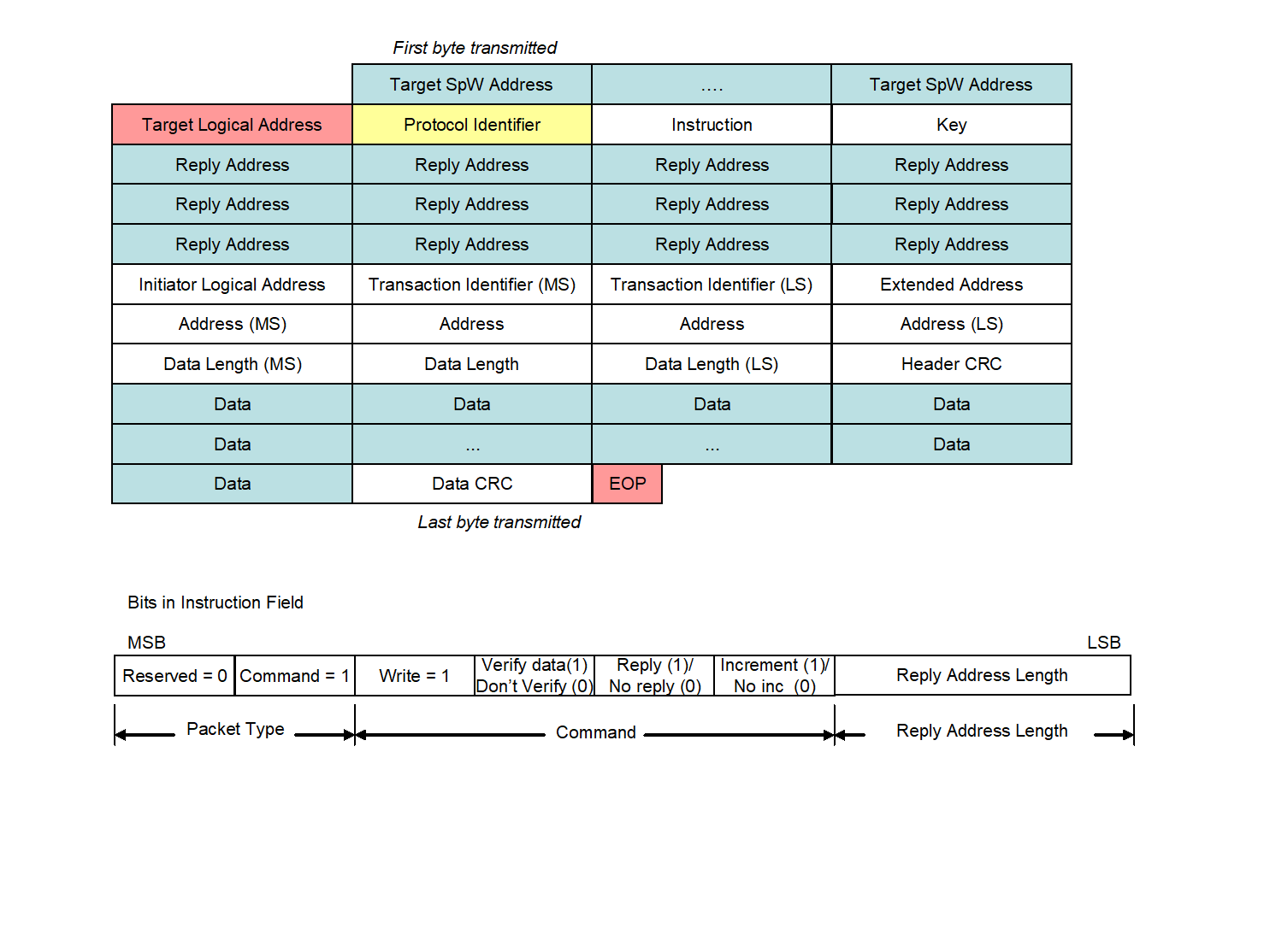 Figure 51: Write Command format
Target SpaceWire Address field
The Target SpaceWire Address field shall be as defined in clause 5.1.1.
Target Logical Address field
The Target Logical Address field shall be as defined in clause 5.1.2.
Protocol Identifier field
The Protocol Identifier field shall be as defined in clause 5.1.3.
Instruction field
Instruction field format
The Instruction field format shall be as defined in clause 5.1.4.
Packet type field
The Packet Type field shall be 0b01 to indicate that this is a command.
Command field
The Write/Read bit shall be set (1) for a write command.
The Verify-Data-Before-Write bit shall be:
- Set (1) if the data is to be checked before it is written to memory, and
- Clear (0) otherwise. The Reply bit shall be:
- Set (1) if a reply to the write command is required, and
- Clear (0) otherwise. The Increment/No increment Address bit shall be:
- Set (1) if data is written to sequential memory addresses, and.
- Clear (0) if data is written to a single memory address.
Reply Address length field
The Reply Address Length field shall be set to the smallest number of 32-bit words that is able to contain the Reply SpaceWire Address from the target, back to the initiator of the command packet or some other node that is to receive the reply.
For example, if three Reply SpaceWire Address bytes are used then the Reply Address Length field is set to one (0b01).
Key field
The Key field shall be as defined in clause 5.1.5.
Reply Address field
The Reply Address field shall be as defined in clause 5.1.6.
Initiator Logical Address field
The Initiator Logical Address field shall be as defined in clause 5.1.7.
Transaction Identifier field
The Transaction Identifier field format shall be as defined in clause 5.1.8.
Extended Address field
The Extended Address field shall be as defined in clause 5.1.9.
The Extended Address field shall hold the most-significant 8-bits of the starting memory address to be written to.
Address field
The Address field format shall be as defined in clause 5.1.10.
The Address field shall hold the least-significant 32-bits of the starting memory address to which the data in a write command is written.
Data Length field
The Data Length field format shall be as defined in clause 5.1.11.
This gives a maximum Data Length of 16 Megabytes -1 in a single write command. If a single byte is being written this field is set to one. If set to zero then no bytes are written to memory which can be used as a test transaction depending upon the implementation.
Header CRC field
The Header CRC field shall contain an 8-bit CRC as defined in clauses 5.1.12 and 5.2.
Data field
The Data field shall contain zero or more bytes of data that are written into the memory of the target as defined in clause 5.1.13.
Data CRC field
The Data CRC shall contain an 8-bit CRC as defined in clauses 5.1.15 and 5.2.
EOP character
The end of the packet containing the write command shall be indicated by an EOP character.
Write reply format
Format
The format of the reply to a write command shall contain the fields shown in Figure 52.
A reply is sent by the target back to initiator of the write command or to some other node as defined by the Reply Address field if requested in the write command. The reply indicates the success or failure of the write command by the value in the Status field.
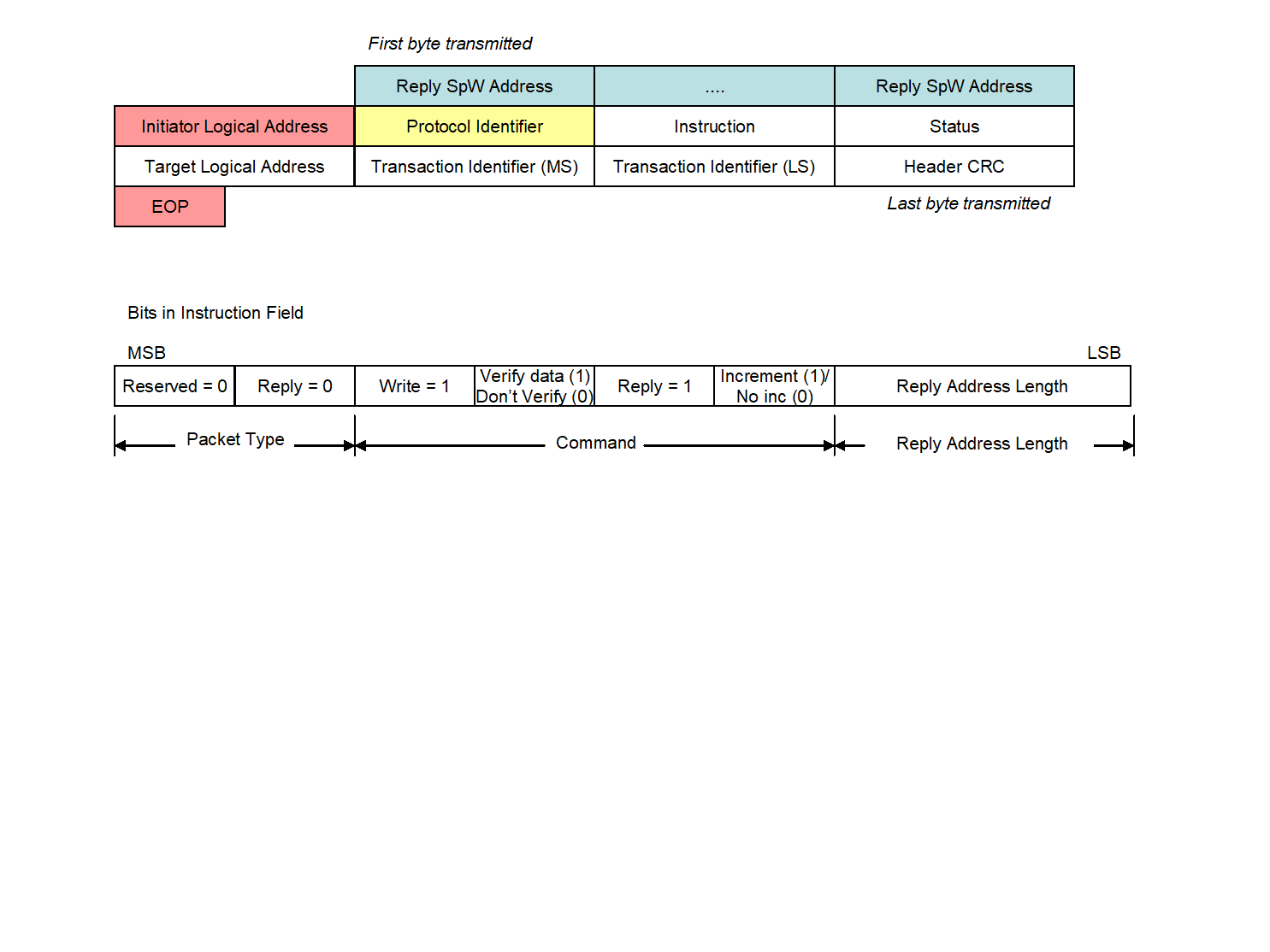 Figure 52: Write Reply format
Reply SpaceWire Address field
The Reply SpaceWire Address field shall comprise zero or more data characters which define how the reply is routed to the initiator or some other node.
The SpaceWire address in the Reply SpaceWire Address field shall be constructed from the Reply Address field in the command as detailed in clause 5.1.6.
Initiator Logical Address field
The Initiator Logical Address field shall be as defined in clause 5.1.7.
Protocol Identifier field
The Protocol Identifier field shall be as defined in clause 5.1.3.
Instruction field
The Instruction field format shall be as defined in clause 5.1.4.
The Packet Type field shall be 0b00 to indicate that the RMAP packet is a reply.
The Command field shall be set to the same value as in the Command field of the write command, clause 5.3.1.5.3.
The Reply Address Length field shall be set to the same value as in the Reply Address Length field of the write command, clause 5.3.1.5.4.
Status field
The Status field format shall be as defined in clause 5.1.17.
The Status field shall contain:
- 0x00 if the command executed successfully.
- A non-zero error code if there was an error with the write command as specified in clause 5.6.
Target Logical Address field
The Target Logical Address field shall be set to either of:
- the value of the Target Logical Address field of the write command, see clause 5.3.1.3, or
- a logical address of the target.
Normally these are the same.
Transaction Identifier field
The Transaction Identifier field shall be set to the same value as the Transaction Identifier in the write command, see clause 5.3.1.9.
This is so that the initiator of the write command can associate the reply with the original write command.
Header CRC field
The Header CRC field shall contain an 8-bit CRC as defined in clauses 5.1.12 and 5.2.
EOP character
The end of the Packet containing the write reply shall be indicated by an EOP character.
Write action
Overview
The normal sequence of actions for a write command is illustrated in Figure 53.
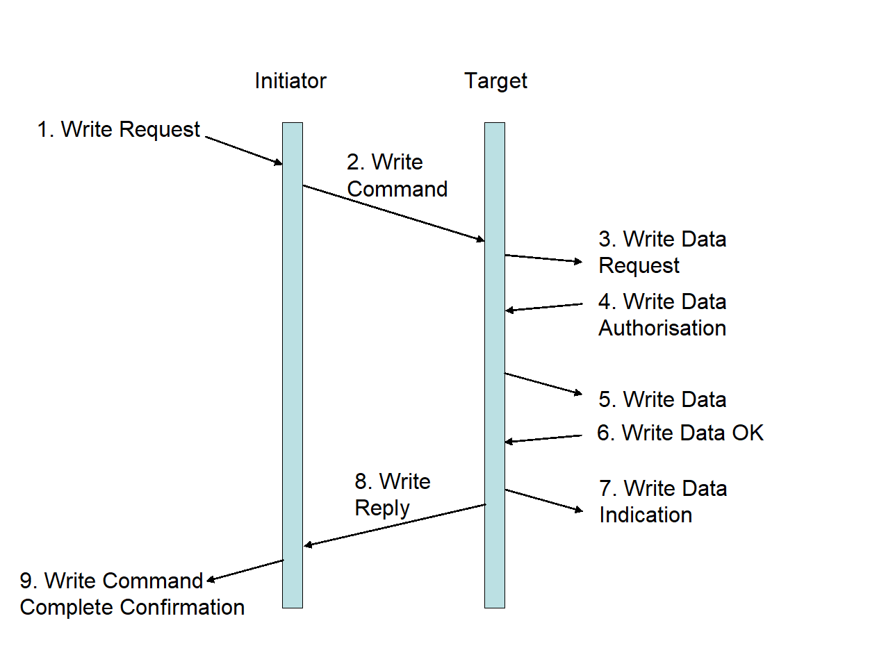 Figure 53: Write Command/Reply sequence
Write request
The write command sequence shall begin when an initiator user application requests to perform a write operation (Write Request).
The initiator user application shall pass the following information to the initiator:
- Target SpaceWire Address
- Target Logical Address
- Write command options
- Key
- Reply Address (if needed)
- Initiator Logical Address
- Transaction Identifier
- Extended Address
- Memory address
- Data Length
- Data
Write command
In response to the write request the initiator shall construct the write command including the Header CRC and Data CRC and send it across the SpaceWire network to the target (Write Command).
The Target SpaceWire Address and Target Logical Address are used to route the command packet to the target.
Write data request
Protocol identifier
When a Packet is received at the target and the Protocol Identifier field is 0x01 the packet shall be regarded as an RMAP packet.
Incomplete header
If an EEP or EOP is received before the complete header including header CRC has been received the target shall:
- Discard the entire packet,
- Not send a reply packet. If an EEP or EOP is received before the complete header including header CRC has been received the target should update the error information to reflect the “EEP” or “Early EOP” error if the target supports error information gathering.
Error End of Packet
If an EEP is received immediately after the complete header including header CRC has been received the target shall:
- Discard the entire packet,
- Not send a reply packet. If an EEP is received immediately after the complete header including header CRC has been received the target should update the error information to reflect the “EEP” error if the target supports error information gathering.
Header CRC check
When an RMAP packet is received at the target the Header CRC shall be checked.
Header CRC error
When checking the Header CRC indicates an error in the header the target shall:
- Discard the entire packet,
- Not send a reply packet. When checking the Header CRC indicates an error in the header the target should update the error information to reflect the “Header CRC” error if the target supports error information gathering.
The sequence of events that occurs when there is a CRC error in the header of the write command is illustrated in Figure 54.
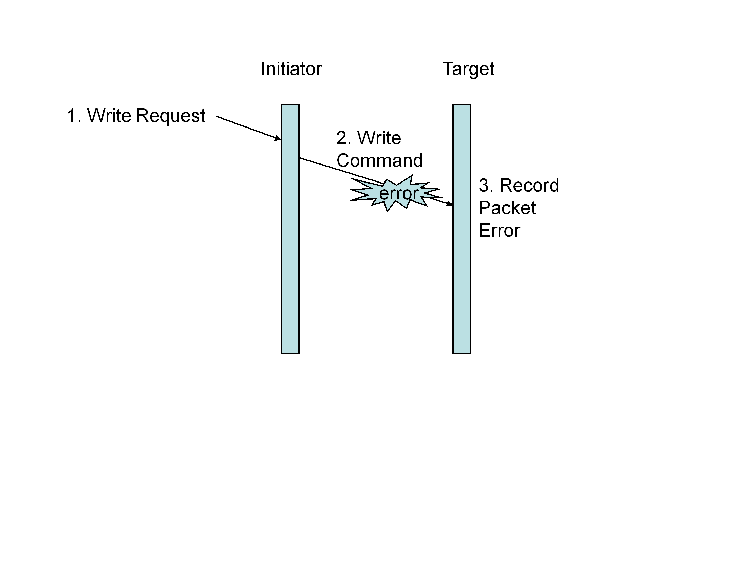 Figure 54: Write Command Header Error
Unused packet type
When checking the Header CRC indicates no error present in the header and if the Instruction field contains an unused packet type (0b10 or 0b11), the target shall:
- Discard the command packet,
- Not send a reply.
When checking the Header CRC indicates no error present in the header and if the Instruction field contains an unused packet type (0b10 or 0b11), the target should update the error information to reflect the “unused RMAP packet type or command code” error if the target supports error information gathering.
When checking the Header CRC indicates no error present in the header and if the Instruction field contains an unused packet type (0b10 or 0b11), the target may send a reply containing an “unused RMAP packet type or command code” error as specified in clause 5.6 to the node specified in the Reply Address and Initiator Logical Address fields, if a reply has been requested (Reply bit set).
Invalid command code
When checking the Header CRC indicates no error present in the header and if the Instruction field contains an invalid command code as specified in Table 51, the target shall:
- Discard the command packet,
- Return an “unused RMAP packet type or command code” error as specified in clause 5.6 to the node specified in the Reply Address and Initiator Logical Address fields, if a reply has been requested (Reply bit set). When checking the Header CRC indicates no error present in the header and if the Instruction field contains an invalid command code, as specified in Table 51 the target should update the error information to reflect the “unused RMAP packet type or command code” error if the target supports error information gathering.
Write data request action
When checking the Header CRC indicates no error present in the header and if the Instruction field contains a write command (packet type 0b01 and a write command code) the target shall pass the following information to the target user application:
- Target Logical Address
- Instruction
- Key
- Initiator Logical Address
- Transaction Identifier
- Extended Address
- Memory address
- Data Length
Write data authorisation
Write operation authorisation
The target user application shall be asked to authorise the write operation.
Invalid key
If the value of the Key is not the value expected by the target user application, the target shall:
- Discard the command packet,
- Return an “invalid key” error as specified in clause 5.6 to the node specified in the Reply Address and Initiator Logical Address fields if a reply has been requested, Reply bit set (1). If the value of the Key is not the value expected by the target user application, the target should update the error information to reflect the “invalid key” error if the target supports error information gathering.
Invalid logical address
If the Target Logical Address is not a logical address recognised by the target user application, the target shall:
- Discard the command packet,
- Return an “invalid Target Logical Address” error as specified in clause 5.6 to the node specified in the Reply Address and Initiator Logical Address fields if a reply has been requested, Reply bit set (1). If the Target Logical Address is not a logical address recognised by the target user application, the target should update the error information to reflect the “invalid Target Logical Address” error if the target supports error information gathering.
Command rejection
If the command is not accepted by the target user application for any other reason, the target shall:
- Discard the command packet,
- Return a “RMAP command not implemented or not authorised” error as specified in clause 5.6 to the node specified in the Reply Address and Initiator Logical Address fields if a reply has been requested, Reply bit set (1). If the command is not accepted by the target user application for any other reason, the target should update the error information to reflect the “RMAP command not implemented or not authorised” error if the target supports error information gathering.
- 1 The target user application can reject the command for any reason it likes. For example the address is not 32-bit aligned, the Data Length is not a multiple of 4-bytes, or the address range falls partially or completely outside an acceptable memory address region.
- 2 The sequence of events that occurs when a write command is not authorised is illustrated in Figure 55.
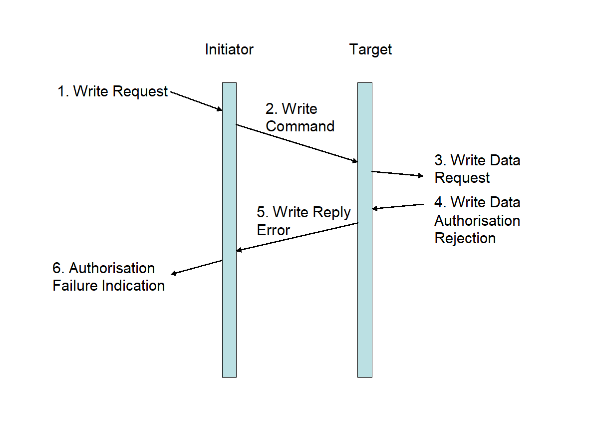 Figure 55: Write Data Authorisation Rejection
Write data
Write data action
If authorisation is given by the target user application, the data contained in the write command shall be written into the memory location in the target specified by the Extended Address and Address fields (Write Data in Figure 53).
Verify-Data-Before-Write bit set
If the Verify-Data-Before-Write bit is set (1) in the command field of the header the data shall be buffered and checked using the Data CRC before it is written to memory.
The size of the Verify-Data-Before-Write data buffer is implementation dependent.
Buffer space exceeded
If the Verify-Data-Before-Write bit is set (1) in the command field of the header and if the data exceeds the available buffer space, the target shall:
- Not write data to memory,
- Return a “verify buffer overrun” error as specified in clause 5.6 to the node specified in the Reply Address and Initiator Logical Address fields if a reply has been requested, Reply bit set (1). If the Verify-Data-Before-Write bit is set (1) in the command field of the header and if the data exceeds the available buffer space, the target should update the error information to reflect the “verify buffer overrun” error if the target supports error information gathering.
Verify-Data-Before-Write action
If the Verify-Data-Before-Write bit is set (1) in the command field of the header and if the Data CRC is correct and the amount of data matches the value of the data length field, the data shall be written from the buffer into memory.
Data CRC error
If the Verify-Data-Before-Write bit is set (1) in the command field of the header and if the Data CRC is in error, the target shall:
- Not write data to memory,
- Return an “invalid Data CRC” error as specified in clause 5.6 to the node specified in the Reply Address and Initiator Logical Address fields if a reply has been requested, Reply bit set (1). If the Verify-Data-Before-Write bit is set (1) in the command field of the header and if the Data CRC is in error, the target should update the error information to reflect the “invalid Data CRC” error if the target supports error information gathering.
Unexpected EOP
If the Verify-Data-Before-Write bit is set (1) in the command field of the header and if there is less data in the data field than specified in the Data Length field of the write command header when the is reached, the target shall:
- Not write data into memory,
- Return an “early EOP” error as specified in clause 5.6 to the node specified in the Reply Address and Initiator Logical Address fields if a reply has been requested, Reply bit set (1). If the Verify-Data-Before-Write bit is set (1) in the command field of the header and if there is less data in the data field than specified in the Data Length field of the write command header when the is reached, the target should:
- Indicate that an insufficient data error has occurred to the user application in the target,
- Update the error information to reflect the insufficient data error if the target supports error information gathering.
More data than expected
If the Verify-Data-Before-Write bit is set (1) in the command field of the header and if there is more data in the data field than specified in the Data Length field of the write command header, the target shall:
- Not write data into memory,
- Discard the rest of the packet,
- Return a “too much data” error as specified in clause 5.6 to the node specified in the Reply Address and Initiator Logical Address fields if a reply has been requested, Reply bit set (1). If the Verify-Data-Before-Write bit is set (1) in the command field of the header and if there is more data in the data field than specified in the Data Length field of the write command header, the target should update the error information to reflect “too much data” error if the target supports error information gathering.
Error End of Packet
If the Verify-Data-Before-Write bit is set (1) in the command field of the header and if the packet ends in an EEP, the target shall:
- Not write data into memory,
- Return an “EEP” error as specified in clause 5.6 to the node specified in the Reply Address and Initiator Logical Address fields if a reply has been requested, Reply bit set (1). If the Verify-Data-Before-Write bit is set (1) in the command field of the header and if the packet ends in an EEP, the target should:
- Indicate that an “EEP” error has occurred to the user application in the target,
- Update the error information to reflect the “EEP” error if the target supports error information gathering,
Verify-Data-Before-Write bit not set
If the Verify-Data-Before-Write bit is clear (0) in the command field of the header the data shall be written directly to memory without necessarily buffering and checking of the Data CRC before the actual write operation is performed.
Data CRC error
If the Verify-Data-Before-Write bit is clear (0) in the command field of the header and if there is a Data CRC error the target shall:
- Update the error information to reflect the “invalid Data CRC” error if the target supports error information gathering,
- Return an “invalid Data CRC” error as specified in clause 5.6 to the node specified in the Reply Address and Initiator Logical Address fields if a reply has been requested, Reply bit set (1).
- 1 If verify before write bit is clear (0) then the Data CRC error is reported after the data has been transferred to target memory.
- 2 The sequence of events that occurs when the Data CRC detects an error in the data field is illustrated in Figure 56.
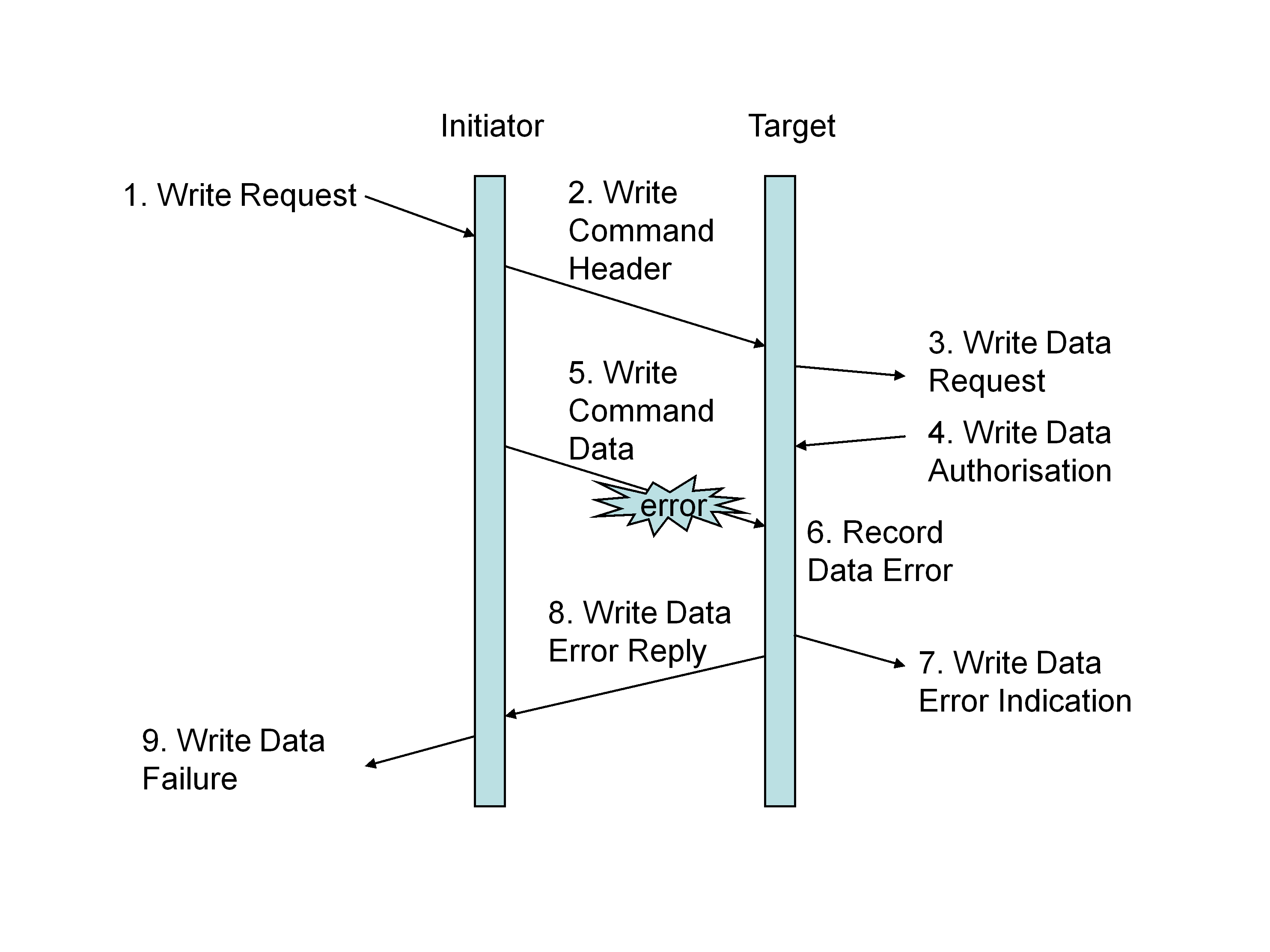 Figure 56: Write Command Data Error
Unexpected EOP
If the Verify-Data-Before-Write bit is clear (0) in the command field of the header and if there is less data in the data field than specified in the Data Length field of the write command header when the is reached, the target shall:
- Stop transferring into target memory,
- Return an “early EOP” error as specified in clause 5.6 to the node specified in the Reply Address and Initiator Logical Address fields if a reply has been requested, Reply bit set (1). If the Verify-Data-Before-Write bit is clear (0) in the command field of the header and if there is less data in the data field than specified in the Data Length field of the write command header when the is reached, the target should:
- Indicate that an “insufficient data” error has occurred to the user application in the target,
- Update the error information to reflect the “insufficient data” error if the target supports error information gathering.
If there is a Data CRC in the packet prior to the EOP then it can be incorrectly transferred into memory at the end of the data.
More data than expected
If the Verify-Data-Before-Write bit is clear (0) in the command field of the header and if there is more data in the data field than specified in the Data Length field of the write command header, the target shall:
- Transfer the amount of data specified by the Data Length field of the write command header to memory,
- Discard the rest of the packet,
- Return a “too much data” error as specified in clause 5.6 to the node specified in the Reply Address and Initiator Logical Address fields if a reply has been requested, Reply bit set (1). If the Verify-Data-Before-Write bit is clear (0) in the command field of the header and if there is more data in the data field than specified in the Data Length field of the write command header, the target should update the error information to reflect “too much data” error if the target supports error information gathering.
Error End of Packet
If the Verify-Data-Before-Write bit is clear (0) in the command field of the header and if the packet ends in an EEP, the target shall:
- Stop transferring data into target memory,
- Return an “EEP” error as specified in clause 5.6 to the node specified in the Reply Address and Initiator Logical Address fields if a reply has been requested, Reply bit set (1). If the Verify-Data-Before-Write bit is clear (0) in the command field of the header and if the packet ends in an EEP, the target should:
- Indicate that an EEP error has occurred to the user application in the target,
- Update the error information to reflect the “EEP” error if the target supports error information gathering.
Increment bit
If the Increment bit is clear (0) in the command field of the header, the memory address written to in the target shall remain constant i.e. all data in the write command is written to the same memory location.
If the Increment bit is set (1) in the command field of the header, the memory address written to in the target shall be incremented as determined by the target user application in order to access sequential memory locations i.e. the data in the write command is written to sequential memory locations.
The width of the memory locations is determined by the target user application. Byte addressing is not necessarily implied.
Write data indication
Once data has been written to memory the target user application should be informed that a write operation has taken place (Write Data Indication).
If data is not written to memory after authorisation has been given for the write to memory, the target user application should be informed that an error occurred.
Write reply
If the Reply bit in the command field is set (1) requesting a reply and the write command was executed successfully, the target shall send a reply packet with the status field set to 0x00 indicating that there was no error to the node specified by the Reply Address and Initiator Logical Address fields of the write command (Write Reply).
If the Reply bit in the command field is clear (0), the target shall not send a reply.
Write command complete confirmation
When the write reply is received at the initiator (or other node specified by the Reply Address and Initiator Logical Address), successful completion of the write request or its failure shall be indicated to the user application on that node (Write Complete Confirmation).
The Transaction Identifier shall be used to relate the reply to the command that caused the reply.
Write not OK
If the write operation to memory fails, the target should stop writing to memory as soon as the memory error is detected.
If the write operation to memory fails, the target should update the error information to reflect the memory access error if the target supports error information gathering.
If the write operation to memory fails, the target shall return a “General” error as specified in clause 5.6 to the node specified in the Reply Address field and Initiator Logical Address fields if a reply has been requested, Reply bit set (1).
Corrupted write reply
If the write reply is corrupted or does not reach the initiator (or other node specified by the Reply Address) intact the initiator shall discard the reply.
If the write reply is corrupted or does not reach the initiator (or other node specified by the Reply Address) intact the initiator should:
- Update the error information to reflect the invalid reply error, if the initiator or other node receiving the invalid reply supports error information gathering,
- Indicate an error to the user application in the node receiving the reply.
- 1 The sequence of events that occurs when a write reply error occurs is illustrated in Figure 57.
- 2 The data has been written into target memory and the target user application has been informed. The initiator application is informed when a write reply is received. It is not informed when no reply is received.
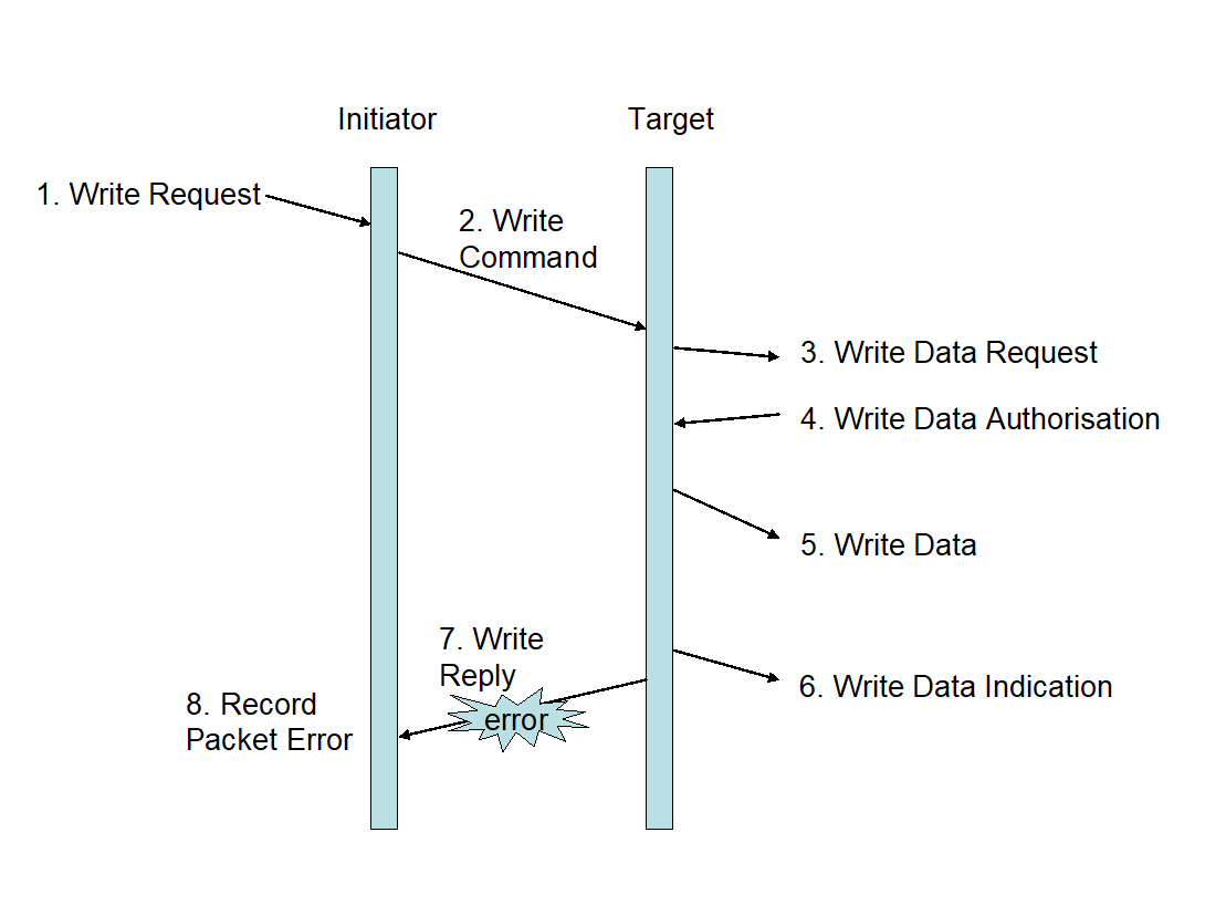 Figure 57: Write Reply Error
Invalid reply
When a reply is received by the initiator (or other node specified by the Reply Address) with the reserved bit in the instruction field set (1) or with the command/reply bit clear (0), the initiator shall discard the reply.
When a reply is received by the initiator (or other node specified by the Reply Address) with the reserved bit in the instruction field set (1) or with the command/reply bit clear (0), the initiator should update the error information to reflect the invalid reply error, if the initiator or other node receiving the invalid reply supports error information gathering.
Read Command
Read command format
Fields
The read command shall contain the fields shown in Figure 58.
 Figure 58: Read Command format
Target SpaceWire Address field
The Target SpaceWire Address field shall be as defined in clause 5.1.1.
Target Logical Address field
The Target Logical Address field shall be as defined in clause 5.1.2.
Protocol Identifier field
The Protocol Identifier field shall be as defined in clause 5.1.3.
Instruction field
Instruction field format
The Instruction field format shall be as defined in clause 5.1.4.
Packet type field
The Packet Type field shall be 0b01 to indicate that this is a command.
Command field
The Write/Read bit shall be clear (0) for a read command.
The Verify-Data-Before-Write bit shall be clear (0) for a read command.
The Reply bit shall be set (1) for a read command.
The Increment/No increment Address bit shall be:
- Set (1) if data is read from sequential memory addresses,
- Clear (0) if data is read from a single memory address.
Reply Address length field
The Reply Address Length field shall be set to the smallest number of 32-bit words that is able to contain the Reply SpaceWire Address from the target, back to the initiator of the command packet or some other node that is to receive the reply.
For example, if six Reply SpaceWire Address bytes are used then the Reply Address Path Length field is set to two (0b10).
Key field
The Key field shall be as defined in clause 5.1.5.
Reply Address field
The Reply Address field shall be as defined in clause 5.1.6.
Initiator Logical Address field
The Initiator Logical Address field shall be as defined in clause 5.1.7.
Transaction Identifier field
The Transaction Identifier field format shall be as defined in clause 5.1.8.
Extended Address field
The Extended Address field shall be as defined in clause 5.1.9.
The Extended Address field shall hold the most-significant 8-bits of the starting memory address to be read from.
Address field
The Address field format shall be as defined in clause 5.1.10.
The Address field shall hold the least-significant 32-bits of the starting memory address from which data is read.
Data Length field
The Data Length field format shall be as defined in clause 5.1.11.
This gives a maximum Data Length of 16 Megabytes - 1 in a single read command. If a single byte is being read this field is set to one. If set to zero then no bytes are read from memory which can be used as a test transaction depending upon the implementation.
Header CRC
The Header CRC field shall contain an 8-bit CRC as defined in clauses 5.1.12 and 5.2.
EOP character
The end of the Packet containing the read command shall be indicated by an EOP character.
Read reply format
General
The read reply shall contain either:
- the data that was read from the target, or
- an error code indicating why data was not read, or
- both data and an error code.
Format
The format of the reply to a read command shall be as in Figure 59.
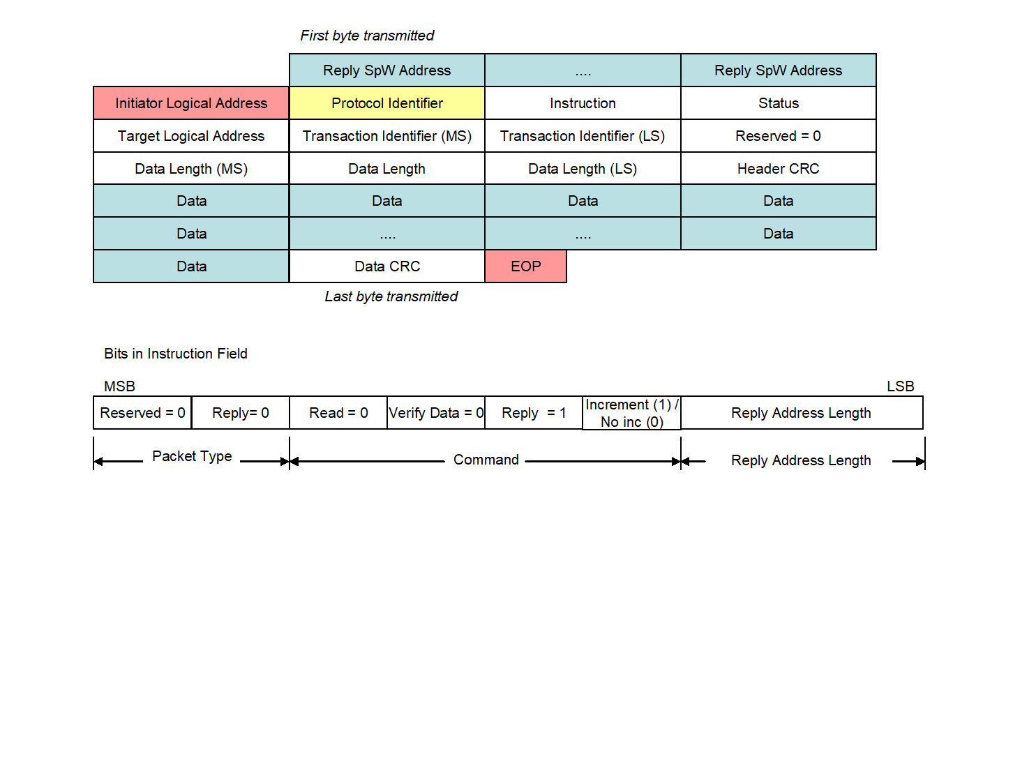 Figure 59: Read Reply format
Reply SpW Address
The Reply SpaceWire Address field shall comprise zero or more data characters which define how the reply is routed to the initiator or some other node.
The SpaceWire address in the Reply SpaceWire Address field shall be constructed from the Reply Address field in the command as detailed in clause 5.1.6.
Initiator Logical Address field
The Initiator Logical Address field shall be as defined in clause 5.1.7.
Protocol Identifier field
The Protocol Identifier field shall be as defined in clause 5.1.3.
Instruction field
The Instruction field format shall be as defined in clause 5.1.4.
The Packet Type field shall be 0b00 to indicate that RMAP packet is a reply.
The Command field shall be set to the same value as in the Command field of the read command, clause 5.4.1.5.3.
The Reply Address Length field shall be set to the same value as in the Reply Address Length field of the read command, clause 5.4.1.5.4.
Status field
The Status field format shall be as defined in clause 5.1.17.
The Status field shall contain:
- 0x00 if the command executed successfully,
- A non-zero error code if there was an error with the read command as specified in clause 5.6.
Target Logical Address field
The Target Logical Address field shall be set to either of:
- The value of the Target Logical Address field of the read command, see clause 5.3.1.3, or
- A logical address of the target.
Normally these are the same.
Transaction Identifier field
The Transaction Identifier field shall be set to the same value as the Transaction Identifier of the read command, see clause 5.4.1.9.
This is so that the initiator of the read command can associate the reply and data in the reply with the original read command when the reply is sent to the initiator.
Data Length field
The Data Length field format shall be as defined in clause 5.1.11.
The Data Length field in the read reply may have a different value than the data length field in the corresponding read command.
Header CRC field
The Header CRC field shall contain a CRC as defined in clauses 5.1.12 and 5.2.
Data field
The Data field shall contain the data that has been read from the memory of the target as defined in clause 5.1.13.
The number of data bytes in the reply may be a different value from that indicated in the Data Length field in the command and reply, if fewer bytes are returned than requested.
If the number of data bytes in the reply is different from the value indicated in the Data Length field the initiator discards the reply as specified in 5.4.3.12.
Data CRC field
The Data CRC shall contain an 8-bit CRC as defined in clauses 5.1.15 and 5.2.
EOP character
The end of the Packet containing the read reply shall be indicated by an EOP character.
Read action
Overview
The normal sequence of actions for a read command is illustrated in Figure 510.
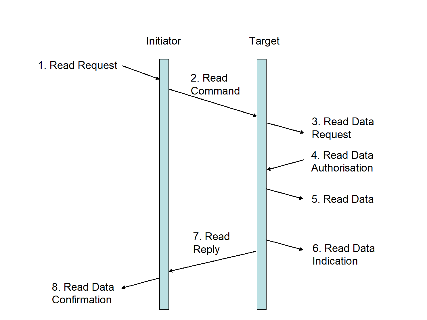 Figure 510: Read Command/Reply sequence
Read Request
The read command sequence shall begin when an initiator user application requests to perform a read operation (Read Request).
The initiator user application shall pass the following information to the initiator:
- Target SpaceWire Address
- Target Logical Address
- Read command options
- Key
- Reply Address
- Initiator Logical Address
- Transaction Identifier
- Extended Address
- Memory address
- Data Length
Read command
In response to the read request the initiator shall construct the read command including the Header CRC and send it across the SpaceWire network to the target (Read Command).
The Target SpaceWire Address and Target Logical Address are used to route the command packet to the target.
Read data request
Protocol identifier
When a Packet is received at the target and the Protocol Identifier field is 0x01 the packet shall be regarded as an RMAP packet.
Incomplete header
If an EEP or EOP is received before the complete header including header CRC has been received the target shall:
- Discard the entire packet,
- Not send a reply packet. If an EEP or EOP is received before the complete header including header CRC has been received the target should update the error information to reflect the “EEP” or “Early EOP” error if the target supports error information gathering.
Error End of Packet
If an EEP is received immediately after the complete header including header CRC has been received the target shall:
- Discard the entire packet,
- Not send a reply packet. If an EEP is received immediately after the complete header including header CRC has been received the target should update the error information to reflect the “EEP” error if the target supports error information gathering.
Header CRC check
When an RMAP packet is received at the target the Header CRC shall be checked.
Header CRC error
When checking the Header CRC indicates an error in the header the target shall:
- Discard the entire packet,
- Not send a reply packet. When checking the Header CRC indicates an error in the header the target shall update the error information to reflect the “Header CRC” error if the target supports error information gathering.
The sequence of events that occurs when there is a CRC error in the header of the read command is illustrated in Figure 511.
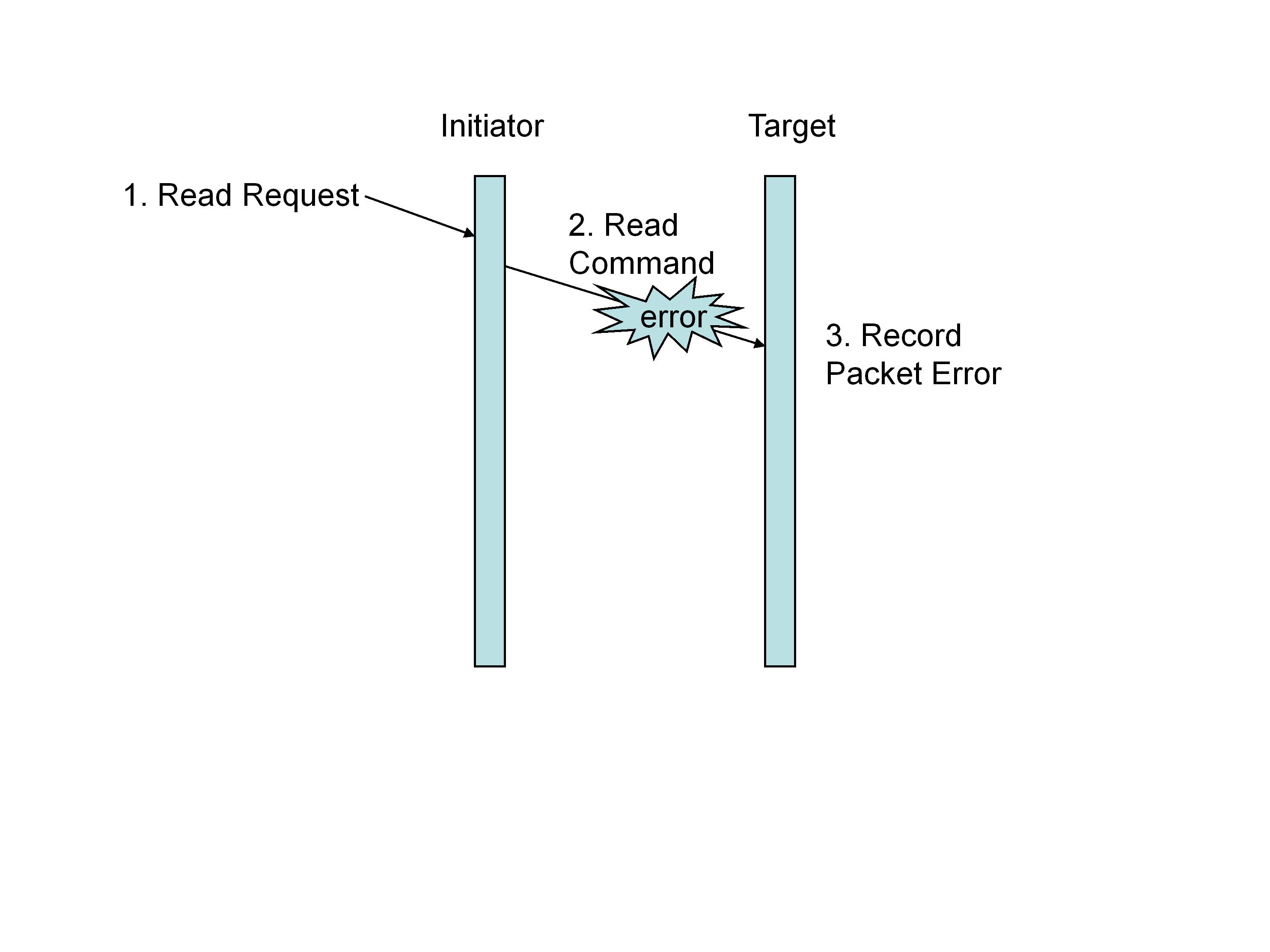 Figure 511: Read Command Header Error
Unused packet type
When checking the Header CRC indicates no error present in the header and if the Instruction field contains an unused packet type (0b10 or 0b11) the target shall:
- Discard the command packet,
- Not send a reply
When checking the Header CRC indicates no error present in the header and if the Instruction field contains an unused packet type (0b10 or 0b11) the target should update the error information to reflect the “unused RMAP packet type of command code” error if the target supports error information gathering.
When checking the Header CRC indicates no error present in the header and if the Instruction field contains an unused packet type (0b10 or 0b11) the target may send a reply containing an “unused RMAP packet type or command code” error as specified in clause 5.6 to the node specified in the Reply Address and Initiator Logical Address fields.
Invalid command code
When checking the Header CRC indicates no error present in the header and if the Instruction field contains an invalid command code as specified in Table 51, the target shall:
- Discard the command packet,
- Return an “unused RMAP packet type or command code” error as specified in clause 5.6 to the node specified in the Reply Address and Initiator Logical Address fields, if a reply has been requested (Reply bit set). When checking the Header CRC indicates no error present in the header and if the Instruction field contains an invalid command code as specified in Table 51, the target should update the error information to reflect the “unused RMAP packet type or command code” error if the target supports error information gathering.
Data characters in read command
When checking the Header CRC indicates no error present in the header and if the Instruction field contains a read command (packet type 0b01 and a read command code) and if one or more data characters are received immediately after the complete header including header CRC the target shall:
- Discard the remainder of the packet,
- Not execute the read command,
- Return a “too much data” error as specified in clause 5.6 to the node specified in the Reply Address and Initiator Logical Address fields. When checking the Header CRC indicates no error present in the header and if the Instruction field contains a read command (packet type 0b01 and a read command code) and if one or more data characters are received immediately after the complete header including header CRC the target should update the error information to reflect the “too much data” error if the target supports error information gathering.
Read data request action
When checking the Header CRC indicates no error present in the header and if the Instruction field contains a read command (packet type 0b01 and a read command code) the target shall pass the following information to the target user application:
- Target Logical Address
- Instruction
- Key
- Initiator Logical Address
- Transaction Identifier
- Extended Address
- Memory address
- Data Length
Read data authorisation
Read operation authorisation
The target user application shall be asked to authorise the read operation.
Invalid key
If the value of the Key is not the value expected by the target user application, the target shall:
- Discard the command packet,
- Return an “invalid key” error as specified in clause 5.6 to the node specified in the Reply Address and Initiator Logical Address fields if a reply has been requested, Reply bit set (1). If the value of the Key is not the value expected by the target user application, the target should update the error information to reflect the “invalid key” error if the target supports error information gathering.
Invalid logical address
If the Target Logical Address is not a logical address recognised by the target user application, the target shall:
- Discard the command packet,
- Return an “invalid Target Logical Address” error as specified in clause 5.6 to the node specified in the Reply Address and Initiator Logical Address fields. If the Target Logical Address is not a logical address recognised by the target user application, the target should update the error information to reflect the “invalid Target Logical Address” error if the target supports error information gathering.
Command rejection
If the command is not accepted by the target user application for any other reason, the target shall:
- Discard the command packet.
- Return an “RMAP command not implemented or not authorised” error as specified in clause 5.6 to the node specified in the Reply Address and Initiator Logical Address fields. If the command is not accepted by the target user application for any other reason, the target should update the error information to reflect the “RMAP command not implemented or not authorised” error if the target supports error information gathering.
- 1 The target user application can reject the command for any reason it likes. For example the address is not 32-bit aligned, the Data Length is not a multiple of 4-bytes, or the address range falls partially or completely outside an acceptable memory address region.
- 2 The sequence of events that occurs when a read command is not authorised is illustrated in Figure 512.
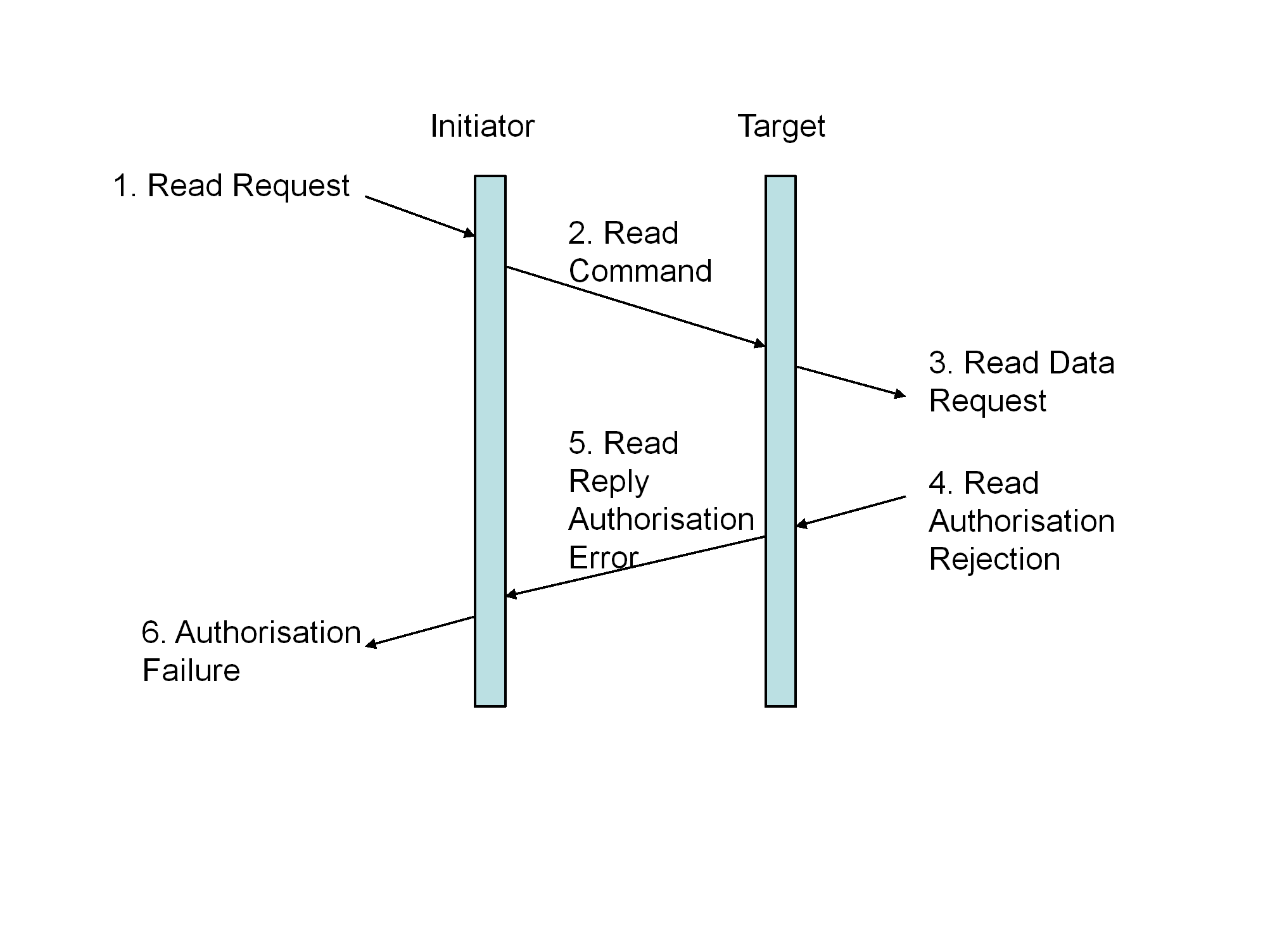 Figure 512: Read Authorisation Rejection
Read data
If authorisation is given by the target user application, data shall be read from the memory location in the target specified by the Extended Address and Address fields (Read Data).
If the Increment bit is clear (0) in the command field of the header, the memory address read from in the target shall remain constant i.e. all data is read from the same memory location.
If the Increment bit is set (1) in the command field of the header, the memory address read in the target shall be incremented as determined by the target user application in order to access sequential memory locations i.e. the data is read from sequential memory locations.
The width of the memory locations is determined by the target user application. Byte addressing is not necessarily implied.
Read data indication
Once data has been read from memory the target user application should be informed that a read operation has taken place (Read Data Indication).
If data is not read from memory after authorisation has been given for the read from memory, the target user application shall be informed that an error occurred.
Read reply
If the read command was executed successfully, the target shall send a reply packet to the node specified by the Reply Address and Initiator Logical Address fields of the read command (Read Reply).
The reply to a successful read command shall have:
- The status field set to 0x00 indicting that there was no error,
- The Data Length field set to the amount of data read in bytes,
- The data field filled with the data read from the target memory.
Read data confirmation
When the read reply is received at the initiator (or other node specified by the Reply Address), successful completion of the read request shall be indicated to the user application on that node (Read Data Confirmation).
The Transaction Identifier shall be used to relate the reply to the command that caused the reply.
It is the responsibility of the initiator user application to read the data in the read reply once it has been informed that the data has been received.
Read not OK
If the read memory operation memory fails, the target should stop reading from memory as soon as the memory error is detected.
If the read memory operation memory fails, the target should update the error information to reflect the memory access error if the target supports error information gathering.
If the read memory operation memory fails, the target shall either:
- Append an EEP to the end of the data already sent in the reply to the initiator, or
- Append an appropriate data CRC byte covering the data already sent in the reply to the initiator, followed by an EOP.
Read reply header error
If the reply from the read command arrives at the initiator (or other node specified by the Reply Address) with a Header CRC error, packet type error, or other error in the header, the receiving node shall discard the entire packet containing the corrupted read reply.
If the reply from the read command arrives at the initiator (or other node specified by the Reply Address) with a Header CRC error, packet type error, or other error in the header, the receiving node should update the error information to reflect the “Packet Error” error if the initiator (or other node receiving the reply) supports error information gathering.
The response to an error in the header of a read reply is illustrated in Figure 513.
 Figure 513: Read Reply Header Error
Read reply data error
If the header of the read reply packet is received intact by the initiator (or other node specified by the Reply Address) but the data field is corrupted as indicated by an incorrect data field length (too long or too short) or by a Data CRC error, the initiator shall discard the reply.
If the header of the read reply packet is received intact by the initiator (or other node specified by the Reply Address) but the data field is corrupted as indicated by an incorrect data field length (too long or too short) or by a Data CRC error, the initiator should:
- Update the error information to reflect the “invalid reply” error, if the initiator or other node receiving the invalid reply supports error information gathering,
- Indicate an error to the user application in the node receiving the reply (Read Data Failure).
The response to an error in the data field of a read reply is illustrated in Figure 514.
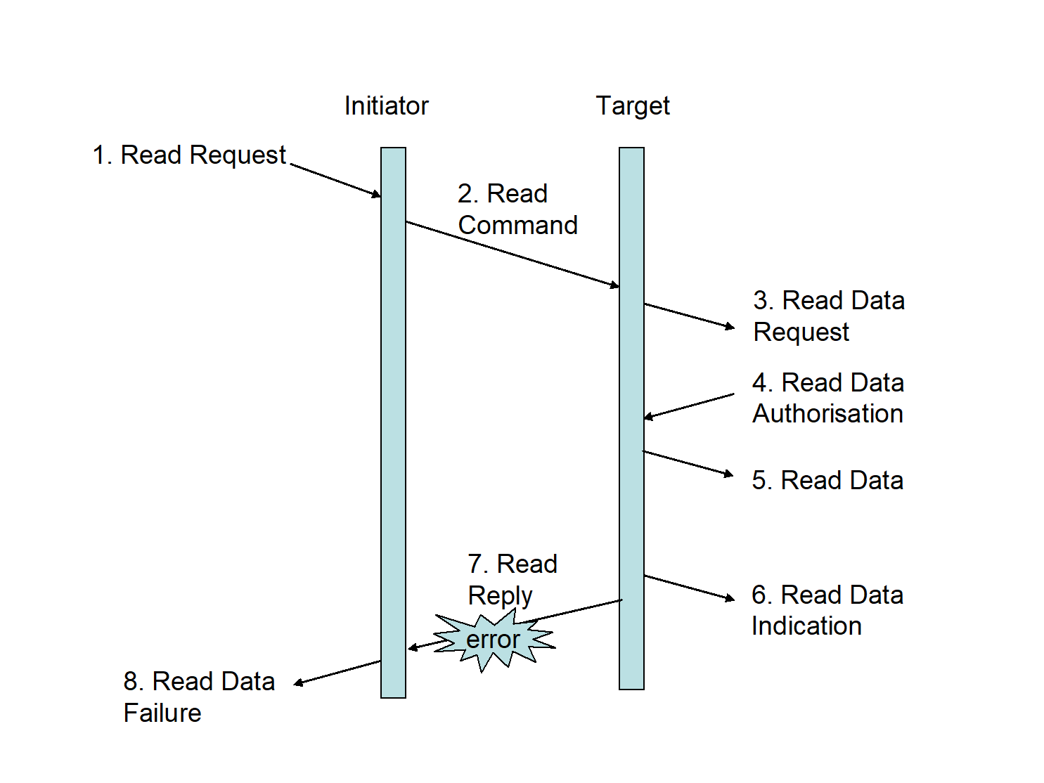 Figure 514: Read Reply Data Error
Invalid reply
When a reply is received by the initiator (or other node specified by the Reply Address) with the reserved bit in the instruction field set (1) or with the command/reply bit clear (0), the initiator shall discard the reply.
When a reply is received by the initiator (or other node specified by the Reply Address) with the reserved bit in the instruction field set (1) or with the command/reply bit clear (0), the initiator should update the error information to reflect the “invalid reply” error, if the initiator or other node receiving the invalid reply supports error information gathering.
Read-Modify-Write Command
Read-modify-write command format
Fields
The read-modify-write command shall contain the fields shown in Figure 515.
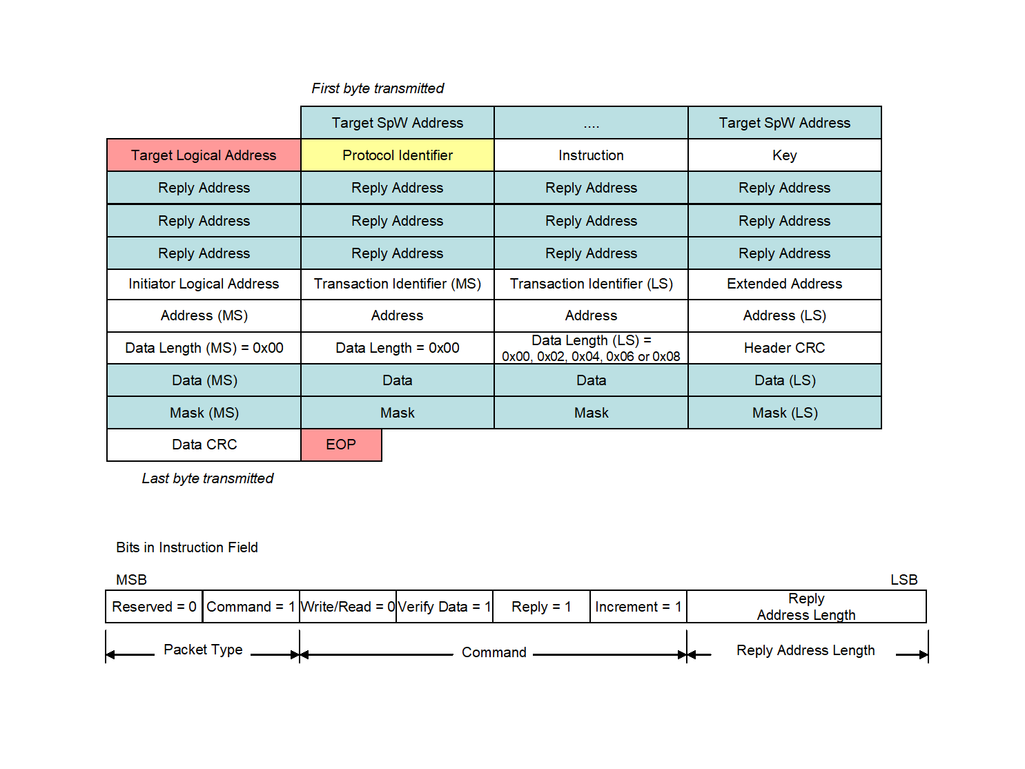 Figure 515: Read-Modify-Write Command format
Target SpaceWire Address field
The Target SpaceWire Address field shall be as defined in clause 5.1.1.
Target Logical Address field
The Target Logical Address field shall be as defined in clause 5.1.2.
Protocol Identifier field
The Protocol Identifier field shall be as defined in clause 5.1.3.
Instruction field
Instruction field format
The Instruction field format shall be as defined in clause 5.1.4.
Packet type field
The Packet Type field shall be 0b01 to indicate that this is a command.
Command field
The Write/Read bit shall be clear (0) for a read-modify-write command.
The Verify-Data-Before-Write bit shall be set (1) for a read-modify-write command.
This is so that the data is verified before it is written to memory and also distinguishes a read-modify-write from a read command.
The Reply bit shall be set (1) for a read-modify-write command.
The reply contains the data initially read from the memory in the target.
The “Increment / No Increment Address” bit shall be set (1) for a read-modify-write command.
This means that when read-modify-write is applied to more than one byte, the address is incremented if byte wide memory is being used. Note that the width of the memory word is determined by the target unit and can be any multiple of 8-bits.
Reply Address length field
The Reply Address Length field shall be set to the smallest number of 32-bit words that is able to contain the Reply SpaceWire Address from the target, back to the initiator of the command packet or some other node that is to receive the reply.
For example, if ten path Reply SpaceWire Address bytes are used then the Reply Address Length field is set to three (0b11).
Key field
The Key field shall be as defined in clause 5.1.5.
Reply Address field
The Reply Address field shall be as defined in clause 5.1.6.
Initiator Logical Address field
The Initiator Logical Address field shall be as defined in clause 5.1.7.
Transaction Identifier field
The Transaction Identifier field format shall be as defined in clause 5.1.8.
Extended Address field
The Extended Address field shall be as defined in clause 5.1.9.
The Extended Address field shall hold the most-significant 8-bits of the starting memory address to be read from.
Address field
The Address field format shall be as defined in clause 5.1.10.
The Address field shall hold the least-significant 32-bits of the memory address to which the data in a read-modify-write command is read from and written to.
Data Length field
The Data Length field format shall be as defined in clause 5.1.11.
The Data Length field shall contain the overall length, in bytes, of the data and mask fields i.e. the length of the data field plus the length of the mask field.
In a read-modify-write command the Data Length shall specify the size of the data field plus the size of the mask field sent in the command, which is twice the amount of data read and written.
For example, if a 2-byte word is written, then the Data Length is 0x04. There are two data bytes and two mask bytes in the command. Two bytes are read from memory and returned to the initiator. Two bytes are written combining the read data, the data from the command and the mask.
The Data Length shall only take on values of 0x00, 0x02, 0x04, 0x06 or 0x08, which correspond to the reading, modifying and writing of 0, 1, 2, 3, or 4 bytes of data respectively.
Header CRC field
The Header CRC field shall contain an 8-bit CRC as defined in clauses 5.1.12 and 5.2.
Data field
The Data field shall contain the data that is combined with the mask and the data read from memory before the result is written into the memory of the target as defined in clause 5.1.13.
The set of 0, 1, 2, 3 or 4 data bytes shall precede the corresponding set of 0, 1, 2, 3, or 4 mask bytes.
Mask field
The Mask field shall be used by the target application to define how the data written to memory is formed.
- 1 The way the read data and mask are combined is application dependent.
- 2 For example, data written can be selected on a bit by bit basis from the data sent in the command when the corresponding mask bit is set (1) or from the data read in the reply when the mask bit is clear (0).
- 3 Written Data = (Mask AND Command_Data) OR (NOT Mask AND Read_Data).
- 4 This example is illustrated in Figure 516. The target user application can implement different schemes for example test and set.
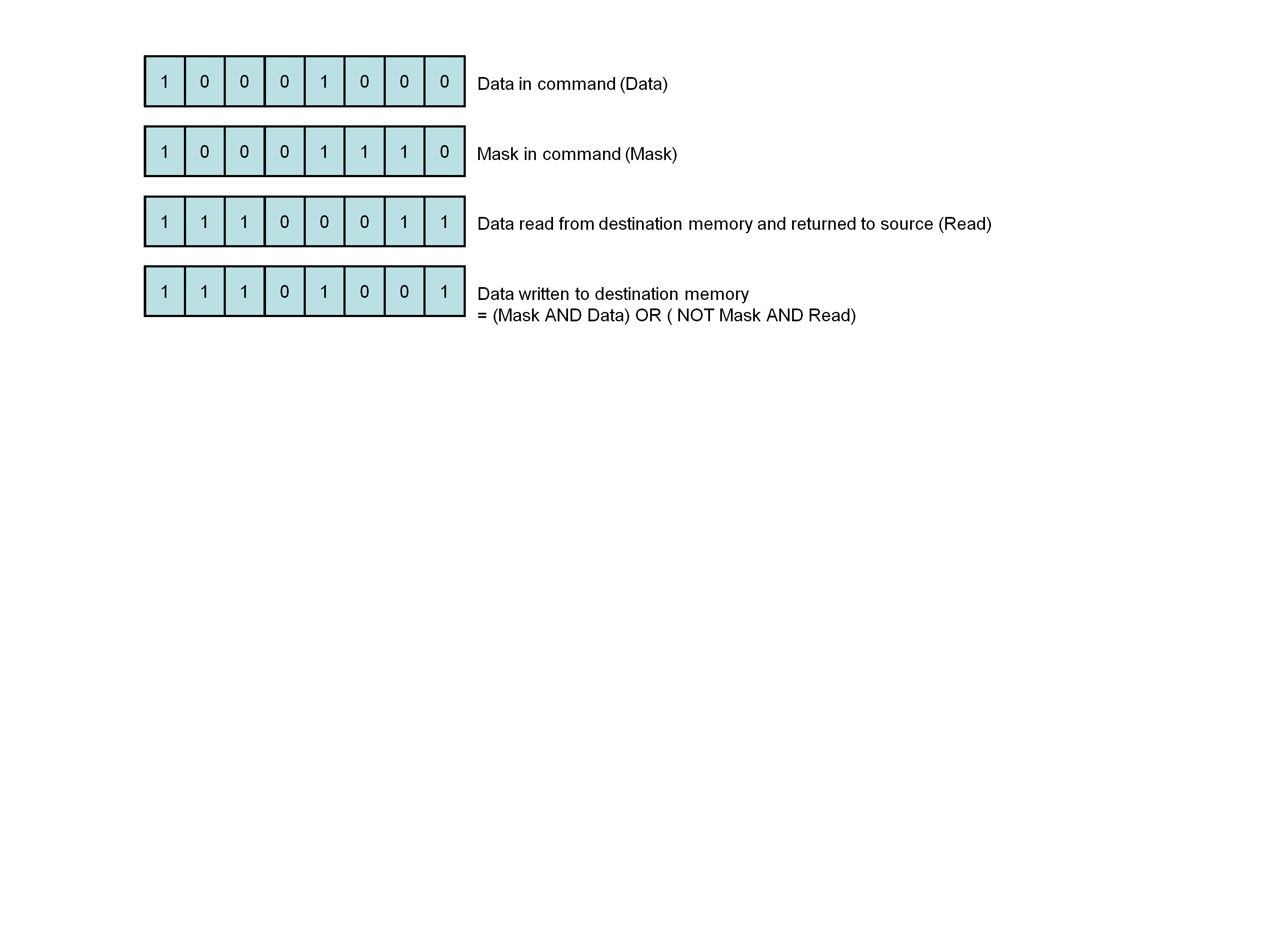 Figure 516: Example Operation of Read-Modify-Write Command
Data CRC field
The Data CRC shall contain an 8-bit CRC as defined in clauses 5.1.15 and 5.2.
The Data CRC shall cover both the data and the mask fields.
EOP character
The end of the Packet containing the read-modify-write command shall be indicated by an EOP character.
Read-modify-write reply format
General
The read-modify-write reply shall contain either:
- the data that was read from the target, or
- an error code indicating why data was not read, or
- both data and an error code.
Format
The format of the reply to a read-modify-write command shall be as in Figure 517.
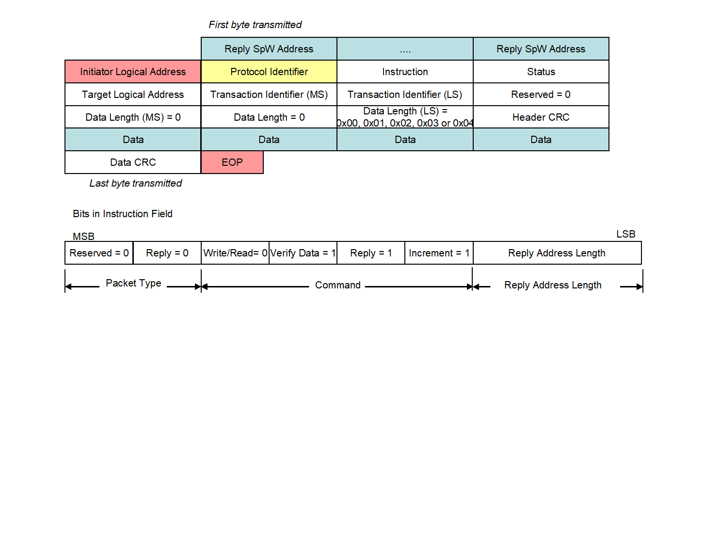 Figure 517: Read-Modify-Write Reply format
Reply SpaceWire Address
The Reply SpaceWire Address field shall comprise zero or more data characters which define how the reply is routed to the initiator or some other node.
The SpaceWire address in the Reply SpaceWire Address field shall be constructed from the Reply Address field in the command as detailed in clause 5.1.6.
Initiator Logical Address field
The Initiator Logical Address field shall be as defined in clause 5.1.7.
Protocol Identifier field
The Protocol Identifier field shall be as defined in clause 5.1.3.
Instruction field
The Instruction field format shall be as defined in clause 5.1.4.
The Packet Type field shall be 0b00 to indicate that RMAP packet is a reply.
The Command field shall be set to the same value as in the Command field of the read-modify-write command, 5.5.1.5.3.
The Reply Address Length field shall be set to the same value as in the Reply Address Length field of the read-modify-write command, clause 5.5.1.5.3.
Status field
The Status field format shall be as defined in clause 5.1.17.
The Status field shall contain:
- 0x00 if the command executed successfully,
- A non-zero error code if there was an error with the read-modify-write command as specified in clause 5.6.
Target Logical Address field
The Target Logical Address field shall be set to either of:
- The value of the Target Logical Address field of the write command, see clause 5.3.1.3, or
- A logical address of the target.
Normally these are the same.
Transaction Identifier field
The Transaction Identifier field shall be set to the same value as the Transaction Identifier of the read-modify-write command, see clause 5.5.1.9.
This is so that the initiator of the read-modify-write command can associate the reply and data in the reply with the original read-modify-write command.
Data Length field
The Data Length field format shall be as defined in clause 5.1.11.
The Data Length field shall contain the length, in bytes, of the data returned in the reply packet.
For a read-modify-write command the Data Length shall be 0, 1, 2, 3 or 4 only.
The Data Length in the reply is a different value to the Data Length in the command since the Data Length in the command includes both data and mask.
Header CRC field
The Header CRC field shall contain a CRC as defined in clauses 5.1.12 and 5.2.
Data field
The Data field shall contain the data that has been read from the memory of the target as defined in clause 5.1.13.
The data length field in the reply is different to that in the command.
Data CRC field
The Data CRC shall contain an 8-bit CRC as defined in clauses 5.1.15 and 5.2.
EOP character
The end of the Packet containing the read-modify-write reply shall be indicated by an EOP character.
Read-modify-write action
Overview
The normal sequence of actions for a read-modify-write command is illustrated in Figure 518.
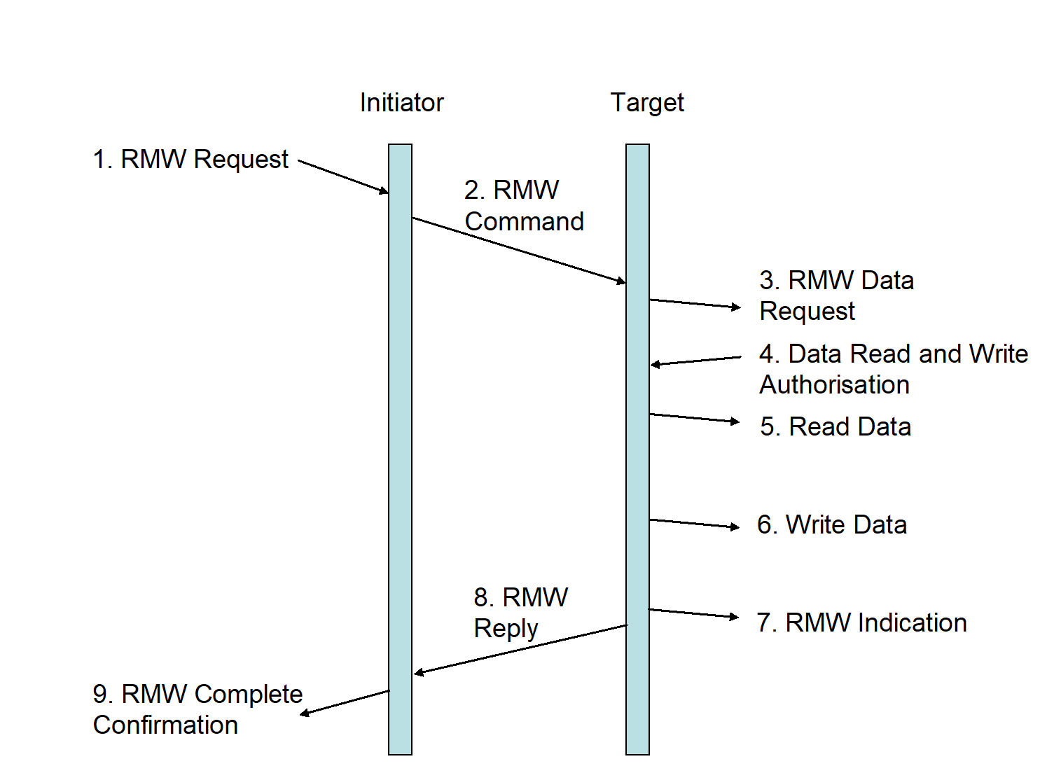 Figure 518: Read-Modify-Write Command/Reply sequence
Read-modify-write request
The read-modify-write command sequence shall begin when an initiator user application requests to perform a read-modify-write operation (RMW Request).
The initiator user application shall pass the following information to the initiator:
- Target SpaceWire Address
- Target Logical Address
- Read-modify-write command options
- Key
- Reply Address
- Initiator Logical Address
- Transaction Identifier
- Extended Address
- Memory address
- Data Length
- Data
- Mask
Read-modify-write command
In response to the read-modify-write request the initiator shall construct the read-modify-write command including the Header CRC and Data CRC and send it across the SpaceWire network to the target (RMW Command).
The Target SpaceWire Address and Target Logical Address are used to route the command packet to the target.
Read-modify-write data request
Protocol identifier
When a Packet is received at the target and the Protocol Identifier field is 0x01 the packet shall be regarded as an RMAP packet.
Incomplete header
If an EEP or EOP is received before the complete header including header CRC has been received the target shall:
- Discard the entire packet,
- Not send a reply packet. If an EEP or EOP is received before the complete header including header CRC has been received the target should update the error information to reflect the an “EEP” or “Early EOP” error if the target supports error information gathering.
Error End of Packet
If an EEP is received immediately after the complete header including header CRC has been received the target shall discard the entire packet.
If an EEP is received immediately after the complete header including header CRC has been received the target should:
- Update the error information to reflect the “EEP” error if the target supports error information gathering,
- Not send a reply packet.
Header CRC check
When an RMAP packet is received at the target the Header CRC shall be checked.
Header CRC error
When the Header CRC indicates an error in the header the target shall:
- Discard the entire packet,
- Not send a reply packet. When the Header CRC indicates an error in the header the target should update the error information to reflect the “Header CRC” error if the target supports error information gathering.
The sequence of events that occurs when there is a CRC error in the header of the read-modify-write command is illustrated in Figure 519.
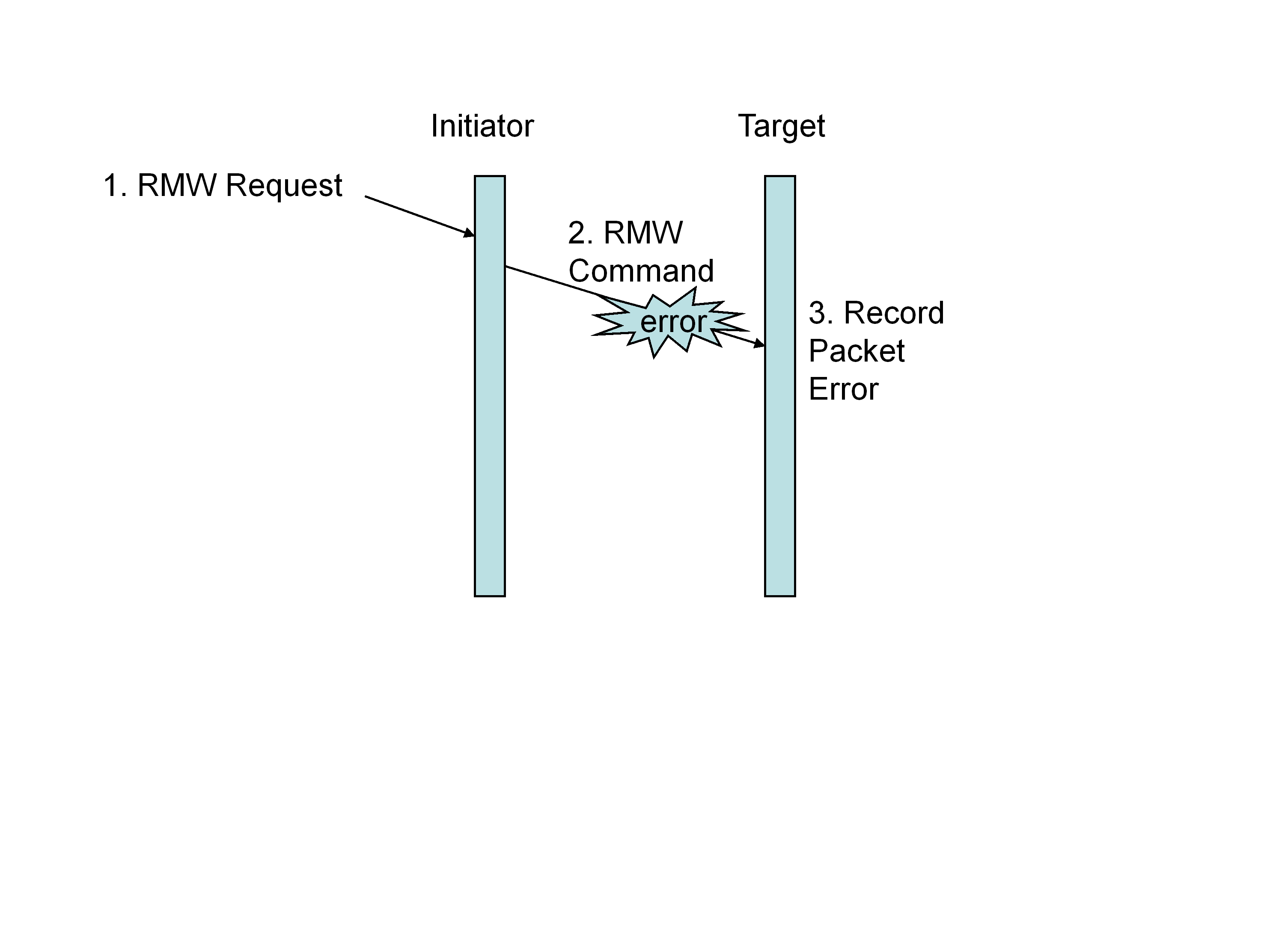 Figure 519: Read-Modify-Write Command Header Error
Unused packet type
When checking the Header CRC indicates no error present in the header and if the Instruction field contains an unused packet type (0b10 or 0b11), the target shall:
- Discard the command packet,
- Not send a reply.
When checking the Header CRC indicates no error present in the header and if the Instruction field contains an unused packet type (0b10 or 0b11), the target should update the error information to reflect the “unused RMAP packet type of command code” error if the target supports error information gathering.
When checking the Header CRC indicates no error present in the header and if the Instruction field contains an unused packet type (0b10 or 0b11), the target may send a reply containing an “unused RMAP packet type or command code” error as specified in clause 5.6 to the node specified in the Reply Address and Initiator Logical Address fields.
Invalid command code
When checking the Header CRC indicates no error present in the header and if the Instruction field contains an invalid command code as specified in Table 51 the target shall:
- Discard the command packet,
- Return an “unused RMAP packet type or command code” error as specified in clause 5.6 to the node specified in the Reply Address and Initiator Logical Address fields. When checking the Header CRC indicates no error present in the header and if the Instruction field contains an invalid command code as specified in Table 51, the target should update the error information to reflect the “unused RMAP packet type or command code” error if the target supports error information gathering.
Data CRC check
When checking the Header CRC indicates no error present in the header, the data and mask shall be buffered and checked using the Data CRC before command authorisation is requested.
Read-modify-write data action
When checking the Header CRC indicates no error present in the header and if the data exceeds the available buffer space, the target shall:
- Neither read data from, nor write data to memory,
- Return a “verify buffer overrun” error as specified in clause 5.6 to the node specified in the Reply Address and Initiator Logical Address fields. When checking the Header CRC indicates no error present in the header and if the data exceeds the available buffer space, the target should update the error information to reflect the “verify buffer overrun” error if the target supports error information gathering.
Data CRC error
When checking the Header CRC indicates no error present in the header and if the Data CRC is in error the target shall:
- Neither read data from, nor write data to memory,
- Return an “invalid Data CRC” error as specified in clause 5.6 to the node specified in the Reply Address and Initiator Logical Address fields. When checking the Header CRC indicates no error present in the header and if the Data CRC is in error the target should update the error information to reflect the “invalid Data CRC” error if the target supports error information gathering.
Unexpected EOP
When checking the Header CRC indicates no error present in the header and if there is less data in the data field than specified in the Data Length field of the read-modify-write command header when the is reached, the target shall:
- Neither read data from, nor write data to memory,
- Return an “early EOP” error as specified in clause 5.6 to the node specified in the Reply Address and Initiator Logical Address fields. When checking the Header CRC indicates no error present in the header and if there is less data in the data field than specified in the Data Length field of the read-modify-write command header when the is reached, the target should:
- Indicate that an “insufficient data” error has occurred to the user application in the target,
- Update the error information to reflect the “insufficient data” error if the target supports error information gathering.
More data than expected
When checking the Header CRC indicates no error present in the header and if there is more data in the data field than specified in the Data Length field of the read-modify-write command header, then the target shall:
- Neither read data from, nor write data to memory,
- Discard the rest of the packet,
- Return a “too much data” error as specified in clause 5.6 to the node specified in the Reply Address and Initiator Logical Address fields. When checking the Header CRC indicates no error present in the header and if there is more data in the data field than specified in the Data Length field of the read-modify-write command header, then the target should update the error information to reflect “too much data” error if the target supports error information gathering.
Invalid Data Length field
When checking the Header CRC indicates no error present in the header and if the value in the Data Length field is incorrect (i.e. is not 0, 2 ,4, 6 or 8), the target shall:
- Neither read data from, nor write data to memory,
- Return a “read-modify-write Data Length” error as specified in clause 5.6 to the node specified in the Reply Address and Initiator Logical Address fields. When checking the Header CRC indicates no error present in the header and if the value in the Data Length field is incorrect (i.e. is not 0, 2 ,4, 6 or 8), the target should update the error information to reflect “read-modify-write Data Length” error if the target supports error information gathering.
The sequence of events that occurs when there is an error in the data field of the read-modify-write command is illustrated in Figure 520.
Error End of Packet
When checking the Header CRC indicates no error present in the header and if the packet ends in an EEP, the target shall:
- Not write data into memory,
- Return an “EEP” error as specified in clause 5.6 to the node specified in the Reply Address and Initiator Logical Address fields. When checking the Header CRC indicates no error present in the header and if the packet ends in an EEP, the target should:
- Indicate that an “EEP” error has occurred to the user application in the target,
- Update the error information to reflect the “EEP” error if the target supports error information gathering.
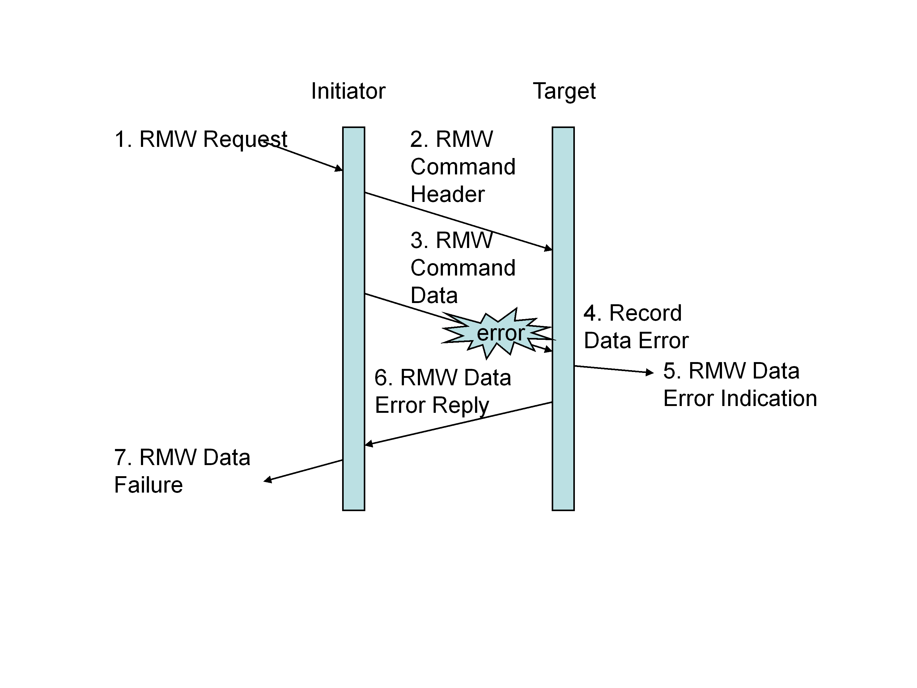 Figure 520: Read-Modify-Write Command Data Error
Read-modify-write data request action
When checking the Header CRC indicates no error present in the header and if the instruction field contains a RMW command and the Data CRC is correct and the amount of data in the data field is correct, the target shall pass the following information to the target user application for command authorisation:
- Target Logical Address
- Instruction
- Key
- Initiator Logical Address
- Transaction Identifier
- Extended Address
- Memory address
- Data Length
Read-modify-write authorisation
Read-modify-write operation authorisation
The target user application shall be asked to authorise the read-modify-write operation.
Invalid key
If the value of the Key is not the value expected by the target user application, the target shall:
- Discard the command packet,
- Return an “invalid key” error as specified in clause 5.6 to the node specified in the Reply Address and Initiator Logical Address fields. If the value of the Key is not the value expected by the target user application, the target should update the error information to reflect the “invalid key” error if the target supports error information gathering.
Invalid logical address
If the Target Logical Address is not a logical address recognised by the target user application, the target shall
- Discard the command packet,
- Return an “invalid Target Logical Address” error as specified in clause 5.6 to the node specified in the Reply Address and Initiator Logical Address fields. If the Target Logical Address is not a logical address recognised by the target user application, the target should update the error information to reflect the “invalid Target Logical Address” error if the target supports error information gathering.
Command rejection
If the command is not accepted by the target user application for any other reason, the target shall:
- Discard the command packet,
- Return an “RMAP command not implemented or not authorised” error as specified in clause 5.6 to the node specified in the Reply Address and Initiator Logical Address fields. If the command is not accepted by the target user application for any other reason, the target should update the error information to reflect the “RMAP command not implemented or not authorised” error if the target supports error information gathering.
- 1 The target user application can reject the command for any reason it likes.
- 2 For example, if the read operation is acceptable, but the write operation is not acceptable, due to for instance a write protected memory, then the command is not authorised by the target user application when the read-modify-write data request is made.
- 3 The sequence of events that occurs when a read-modify-write command is not authorised is illustrated in Figure 521.
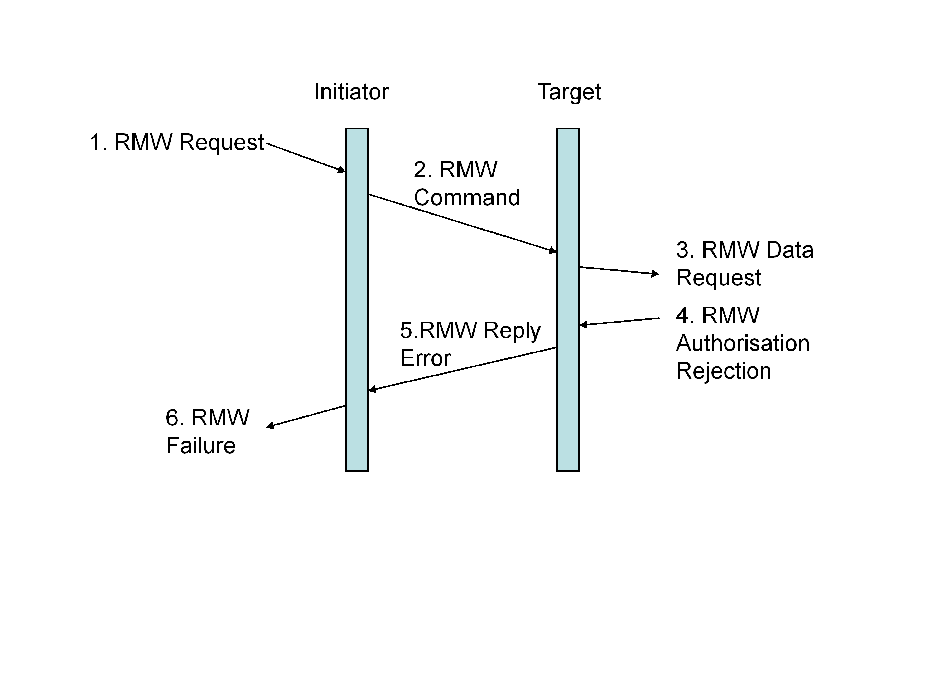 Figure 521: Read-Modify-Write Authorisation Rejection
Read data
If the data to be written does not contain any errors and authorisation is given by the target user application, data shall be read from the memory location in the target specified by the Extended Address and Address fields (Read Data).
The memory address read from in the target shall be incremented as determined by the target user application in order to access sequential memory locations i.e. the data is read from sequential memory locations.
The width of the memory locations is determined by the target user application. Byte addressing is not necessarily implied.
Write data
The data to be written to the memory locations shall be calculated from the data read from memory and the data and mask fields of the read-modify-write command.
The way in which the data read from target memory is combined with the data and mask values in the command is application dependent.
The new data shall be written to the memory location(s) that was previously read.
Read-modify write data indication
Once data has been read and written to memory the user application running on the target should be informed that a read-modify-write operation has taken place (RMW Indication).
If data is not written to memory after authorisation has been given for the read-modify-write to memory, the target user application should be informed that an error occurred.
Read-modify-write reply
If the read-modify-write command was executed successfully, the target shall send a reply packet to the node specified by the Reply Address and Initiator Logical Address fields of the read command (RMW Reply).
The reply to a successful read-modify-write command shall have:
- The status field set to 0x00 indicting that there was no error,
- The Data Length field set to the amount of data read in bytes,
- The data field filled with the data read from the target memory.
Read-modify-write complete confirmation
When the read-modify-write reply is received at the initiator (or other node specified by the Reply Address), successful completion of the read-modify-write request shall be indicated to the user application on that node (RMW Complete Confirmation).
The Transaction Identifier shall be used to relate the reply to the command that caused the reply.
It is the responsibility of the initiator user application to read the data in the read reply once it has been informed that the data has been received.
Read and Write not OK
If the read or write operations to memory fails, the target should stop reading to or writing from memory as soon as the memory error is detected.
If the read or write operations to memory fails, the target should update the error information to reflect the “memory access” error if the target supports error information gathering.
If the read or write operations to memory fails, the target shall either:
- Append an EEP to the end of the data sent in the reply to the initiator, or
- Append an appropriate data CRC byte covering the data sent in the reply to the initiator, followed by an EOP.
In this case the data length field in the reply contains the amount of data requested which is different to the amount of data returned in the data field of the reply.
Read-modify-write reply header error
If the reply from the read-modify-write command arrives at the initiator (or other node) with a Header CRC error, packet type error, or other error in the header, the receiving node shall discard the entire packet containing the corrupted read-modify-write reply.
If the reply from the read-modify-write command arrives at the initiator (or other node) with a Header CRC error, packet type error, or other error in the header, the receiving node should update the error information to reflect the “Packet Error” error if the initiator (or other node receiving the reply) supports error information gathering.
The response to an error in the header of a read-modify-write reply is illustrated in Figure 522. The data has been correctly read from target memory, modified using the mask information and the result written back into memory. The target application has been informed. The read-modify-write reply that is sent back to the initiator is corrupted.
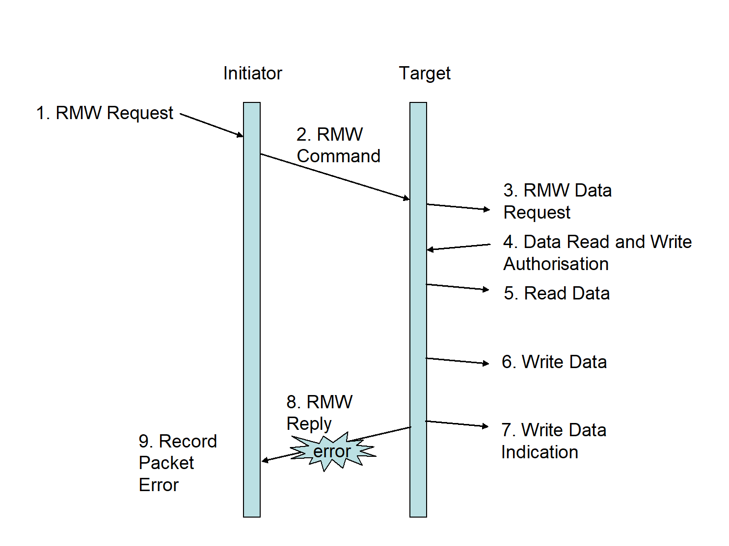 Figure 522: Read-Modify-Write Reply Error
Read-modify-write reply data error
If the header of the read-modify-write reply packet is received intact by the initiator (or other node specified by the Reply Address) but the data field is corrupted as indicated by an incorrect data field length (too long or too short) or by a Data CRC error, the initiator shall discard the reply.
If the header of the read-modify-write reply packet is received intact by the initiator (or other node specified by the Reply Address) but the data field is corrupted as indicated by an incorrect data field length (too long or too short) or by a Data CRC error, the initiator should:
- Update the error information to reflect the “invalid reply” error, if the initiator or other node receiving the invalid reply supports error information gathering.
- Indicate an error to the user application in the node receiving the reply (Read-Modify-Write Data Failure).
The response to an error in the data field of a read reply is illustrated in Figure 523.
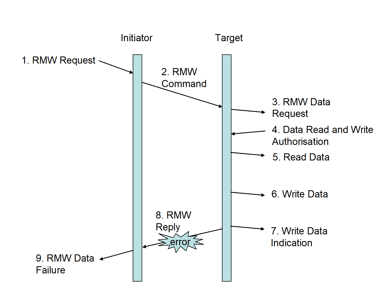 Figure 523: RMW Reply Data Error
Invalid reply
When a reply is received by the initiator (or other node specified by the Reply Address) with the reserved bit in the instruction field set (1) or with the command/reply bit clear (0), the initiator shall discard the reply.
When a reply is received by the initiator (or other node specified by the Reply Address) with the reserved bit in the instruction field set (1) or with the command/reply bit clear (0), the initiator should update the error information to reflect the “invalid reply” error, if the initiator or other node receiving the invalid reply supports error information gathering.
Error and status codes
Error and status codes
The set of error and status codes that shall be used are listed in Table 54.
If a command executes successfully, then the Error Code 0 shall be used in the Status field of any reply.
If there is an error with the command, then a suitable error code as defined in Table 54 shall be used in the Status field of any reply.
When one or more errors arise that mean more than one error code is applicable it shall be application dependent as to which of the relevant error codes is sent.
The specific error returned may vary depending on the specific application.
Table 54: Error and Status codes
|
Error code
|
Error
|
Error description
|
Applicability
| ||
|
Write
|
Read
|
RMW
| |||
|
0
|
Command executed successfully
|
|
X
|
X
|
X
|
|
1
|
General error code
|
The detected error does not fit into the other error cases or the node does not support further distinction between the errors
|
X
|
X
|
X
|
|
2
|
Unused RMAP Packet Type or Command Code
|
The Header CRC was decoded correctly but the packet type is reserved or the command is not used by the RMAP protocol.
|
X
|
X
|
X
|
|
3
|
Invalid key
|
The Header CRC was decoded correctly but the device key did not match that expected by the target user application
|
X
|
X
|
X
|
|
4
|
Invalid Data CRC
|
Error in the CRC of the data field
|
X
|
|
X
|
|
5
|
Early EOP
|
EOP marker detected before the end of the data
|
X
|
X
|
X
|
|
6
|
Too much data
|
More than the expected amount of data in a command has been received
|
X
|
X
|
X
|
|
7
|
EEP
|
EEP marker detected immediately after the header CRC or during the transfer of data and Data CRC or immediately thereafter. Indicates that there was a communication failure of some sort on the network
|
X
|
X
|
X
|
|
8
|
Reserved
|
Reserved
|
|
|
|
|
9
|
Verify buffer overrun
|
The verify before write bit of the command was set so that the data field was buffered in order to verify the Data CRC before transferring the data to target memory. The data field was longer than able to fit inside the verify buffer resulting in a buffer overrun
|
X
|
|
X
|
|
10
|
RMAP Command not implemented or not authorised
|
The target user application did not authorise the requested operation. This may be because the command requested has not been implemented
|
X
|
X
|
X
|
|
11
|
RMW Data Length error
|
The amount of data in a RMW command is invalid (0x01, 0x03, 0x05, 0x07 or greater than 0x08)
|
|
|
X
|
|
12
|
Invalid Target Logical Address
|
The Header CRC was decoded correctly but the Target Logical Address was not the value expected by the target
|
X
|
X
|
X
|
|
13-255
|
Reserved
|
All unused error codes are reserved
|
|
|
|
Partial Implementations of RMAP
Limited functionality nodes
Types of RMAP node
The functionality shall be provided to implement nodes which are:
- Initiators,
- Targets, or
- Both initiators and targets.
Initiator only node
An initiator shall be able to send RMAP commands and receive RMAP replies.
If an initiator only node receives a command, the command shall be discarded.
The “Command Received by Initiator” error should be recorded.
Target only node
A target shall be able to receive RMAP commands and send replies.
If a target only node receives a reply, the reply shall be discarded.
The “Reply Received by Target” error should be recorded.
Partial implementations
Partial implementations of RMAP may be permitted where only some commands or command options are supported.
For example, a unit that supports write and read command but does not implement the read-modify-write command.
If the target user application is passed a command or a command with options that it does not support then it shall not authorise the command.
If a reply has been requested then the RMAP command not implemented or not authorised error shall be sent back to the initiator (or other node).
See clause 5.6.
RMAP conformance
Overview
Several SpaceWire RMAP compatible subsets can be identified each of which implements only a part of the SpaceWire RMAP standard:
RMAP Write Command / Target only
RMAP Read Command / Target only
RMAP Read-Modify-Write Command / Target only
RMAP Read and Write / Target only
RMAP Initiator
RMAP Initiator and Target
Corresponding subsets of the SpaceWire RMAP standard are defined to which implementations can claim conformance. The form of the conformance statement to use is the one given by the appropriate subset definition in the following clauses.
An RMAP compliant product can implement one or more of these subsets.
RMAP partial implementations
Target only
An implementation of "SpaceWire RMAP Target only" shall conform to all requirements given in clause 5.7.1.3 and may claim such compliance by using the following conformance statement “This product conforms to the SpaceWire RMAP Target only specification of the ECSS SpaceWire Protocols Standard (ECSS-E-ST-50-52)”.
Initiator only
An implementation of "SpaceWire Initiator only" shall conform to all requirements given in 5.7.1.2 and may claim such compliance by using the following conformance statement “This product conforms to the SpaceWire RMAP Initiator only specification of the ECSS SpaceWire Protocols Standard ECSS-E-ST-50-52 )”.
RMAP Write Command
An implementation of "SpaceWire RMAP Write Command" shall conform to all requirements given in Table 55 and may claim such compliance by using the following conformance statement “This product conforms to the SpaceWire RMAP Write specification of the ECSS SpaceWire Protocols Standard (ECSS-E-ST-50-52)”.
The supplier of the RMAP equipment shall provide a table detailing the write characteristics of the RMAP implementation.
An example of the required table is given in Table 56.
Table 55: SpaceWire RMAP write command
|
Relevant clauses
|
Title
|
|
ECSS-E-ST-50-51, Clause 5
|
Protocol Identifier
|
|
5.3
|
Write Command
|
|
5.6
|
Error Codes
|
Table 56: Example of Write Command Product Characteristics
|
Write Command
| |||
|
Action
|
Supported
|
Maximum Data Length (bytes)
|
Non-aligned access accepted
|
|
8-bit write
|
No
|
-
|
-
|
|
16-bit write
|
No
|
-
|
-
|
|
32-bit write
|
Yes
|
12
|
No
|
|
64-bit write
|
No
|
-
|
-
|
|
Verified write
|
Yes
|
4
|
No
|
|
Word or byte address
|
Word address 32-bit aligned
| ||
|
Endian order
|
Little endian i.e. first byte received goes in least significant byte of memory location
| ||
|
Accepted logical addresses
|
0xFE at power-on
| ||
|
Target logical address in reply
|
What was in command
| ||
|
Accepted keys
|
0x20
| ||
|
Accepted address ranges
|
0x00 0000 0000 - 0x00 0000 001C
| ||
|
Address incrementation
|
Incrementing address only
| ||
|
Status codes returned
|
All
| ||
RMAP Read Command
An implementation of the "SpaceWire RMAP Read Command" shall conform to all requirements given in Table 57 and may claim such compliance by using the following conformance statement “This product conforms to the SpaceWire RMAP Read specification of the ECSS SpaceWire Protocols Standard (ECSS-E-ST-50-52)”.
The supplier of the RMAP equipment shall provide a table detailing the read characteristics of the RMAP implementation.
An example of the required table is given in Table 58.
Table 57: SpaceWire RMAP Read Command
|
Relevant clauses
|
Title
|
|
ECSS-E-ST-50-51, Clause 5
|
Protocol Identifier
|
|
5.5
|
Read Command
|
|
5.6
|
Error Codes
|
Table 58: Example Read Command Product Characteristics
|
Read Command
| |||
|
Action
|
Supported
|
Maximum Data Length (bytes)
|
Non-aligned access accepted
|
|
8-bit read
|
No
|
-
|
-
|
|
16-bit read
|
No
|
-
|
-
|
|
32-bit read
|
Yes
|
12
|
No
|
|
64-bit read
|
No
|
-
|
-
|
|
Word or byte address
|
Word address 32-bit aligned
| ||
|
Endian order
|
Big endian i.e. the most significant byte of the memory location is returned as the first byte
| ||
|
Accepted logical addresses
|
0xFE at power-on
| ||
|
Target logical address in reply
|
Logical address of target
| ||
|
Accepted keys
|
0x20
| ||
|
Accepted address ranges
|
0x00 0000 0000 - 0x00 0000 001C
| ||
|
Address incrementation
|
Incrementing address only
| ||
|
Status codes returned
|
All
| ||
RMAP Read-Modify-Write Command
An implementation of the "SpaceWire RMAP Read-Modify-Write Command" shall conform to all requirements given in Table 59 and may claim such compliance by using the following conformance statement “This product conforms to the SpaceWire RMAP Read-Modify-Write specification of the ECSS SpaceWire Protocols Standard (ECSS-E-ST-50-52)”.
The supplier of the RMAP equipment should provide a table detailing the characteristics of the RMAP implementation.
An example of the required table is given in Table 510.
Table 59: SpaceWire RMAP Read-Modify-Write Command
|
Relevant clauses
|
Title
|
|
ECSS-E-ST-50-51, Clause 5
|
Protocol Identifier
|
|
5.4
|
Read-Modify-Write Command
|
|
5.6
|
Error Codes
|
Table 510: Example Read-Modify-Write Command Product Characteristics
|
Read-Modify-Write Command
| |||
|
Action
|
Supported
|
Maximum Data Length (bytes)
|
Non-aligned access accepted
|
|
8-bit read-modify-write
|
No
|
-
|
-
|
|
16-bit read-modify-write
|
No
|
-
|
-
|
|
32-bit read-modify-write
|
Yes
|
4
|
No
|
|
64-bit read-modify-write
|
No
|
-
|
-
|
|
Word or byte address
|
Byte address 32-bit word
| ||
|
Endian order
|
Little endian i.e. first byte received goes in least significant byte of memory location
| ||
|
Accepted logical addresses
|
0xFE at power-on
| ||
|
Target logical address in reply
|
What was in command
| ||
|
Accepted keys
|
0x20
| ||
|
Accepted address ranges
|
0x00 0000 0000 - 0x00 0000 001C
| ||
|
Status codes returned
|
All
| ||
ANNEX(informative)Example of RMAP CRC implementation
Overview
In this example implementations of the CRC used by RMAP are provide in VHDL and C-code.
VHDL implementation of RMAP CRC
-- Cyclic Redundancy Code (CRC) for Remote Memory Access Protocol (RMAP)
-- Purpose:
-- Given an intermediate SpaceWire RMAP CRC byte value and an RMAP header
-- or data byte, return an updated RMAP CRC byte value.
--
-- Parameters:
-- INCRC(7:0) - The intermediate RMAP CRC byte value.
-- INBYTE(7:0) - The RMAP Header or Data byte.
--
-- Return value:
-- OUTCRC(7:0) - The updated RMAP CRC byte value.
--
-- Description:
-- One-to-many implementation: Galois version of LFSR (reverse CRC).
--
-- +---+ +---+ +---+ +---+ +---+ +---+ +---+ +---+
-- out <-+-| 7 |<--| 6 |<--| 5 |<--| 4 |<--| 3 |<--| 2 |<-X-| 1 |<-X-| 0 |<-+
-- | +---+ +---+ +---+ +---+ +---+ +---+ ^ +---+ ^ +---+ |
-- | | | |
-- v | | |
-- in -->X------------------------------------------------+--------+--------+
-- x8 x7 x6 x5 x4 x3 x2 x1 x**0
--
-- Generator polynomial: g(x) = x8 + x2 + x1 + x0
--
-- Notes:
-- The INCRC input CRC value must have all bits zero for the first INBYTE.
--
-- The first INBYTE must be the first Header or Data byte covered by the
-- RMAP CRC calculation. The remaining bytes must be supplied in the RMAP
-- transmission/reception byte order.
--
-- If the last INBYTE is the last Header or Data byte covered by the RMAP
-- CRC calculation then the OUTCRC output will be the RMAP CRC byte to be
-- used for transmission or to be checked against the received CRC byte.
--
-- If the last INBYTE is the Header or Data CRC byte then the OUTCRC
-- output will be zero if no errors have been detected and non-zero if
-- an error has been detected.
--
-- Each byte is inserted in or extracted from a SpaceWire packet without
-- the need for any bit reversal or similar manipulation. The SpaceWire
-- packet transmission and reception procedure does the necessary bit
-- ordering when sending and receiving Data Characters (see ECSS-E-ST-50-12).
--
-- SpaceWire data is sent/received Least Significant Bit (LSB) first:
-- INBYTE(0) is the LSB of SpaceWire data byte (sent/received first)
-- INCRC(0) is the LSB of SpaceWire data byte (sent/received first)
--
function RMAP_CalculateCRC (
  constant INCRC:   in Std_Logic_Vector(7 downto 0);

  constant INBYTE:  in Std_Logic_Vector(7 downto 0))

  return               Std_Logic_Vector is  -- Same range as the two inputs

  -- This variable is to hold the output CRC value.

  variable OUTCRC:     Std_Logic_Vector(7 downto 0);

  -- Internal Linear Feedback Shift Register (LFSR). Note that the

  -- vector indices correspond to the powers of the Galois field

  -- polynomial g(x) which are NOT the same as the indices of the

  -- SpaceWire data byte.

  variable LFSR:       Std_Logic_Vector(7 downto 0);
begin
  -- External to internal bit-order reversal to match indices.

  for i in 0 to 7 loop

     LFSR(7-i) := INCRC(i);

  end loop;

  -- Left shift LFSR eight times feeding in INBYTE bit 0 first (LSB).

  for j in 0 to 7 loop

     LFSR(7 downto 0) := (LFSR(6 downto 2)) &

                         (INBYTE(j) xor LFSR(7) xor LFSR(1)) &

                         (INBYTE(j) xor LFSR(7) xor LFSR(0)) &

                         (INBYTE(j) xor LFSR(7));

  end loop;

  -- Internal to external bit-order reversal to match indices.

  for i in 0 to 7 loop

     OUTCRC(7-i) := LFSR(i);

  end loop;

  -- Return the updated RMAP CRC byte value.

  return OUTCRC;
end function RMAP_CalculateCRC;
C-code implementation of RMAP CRC
/*
-
The local look-up table used to calculate the updated RMAP CRC
-
byte from the intermediate CRC byte and the input byte.
*/
static const unsigned char RMAP_CRCTable[] = {
0x00, 0x91, 0xe3, 0x72, 0x07, 0x96, 0xe4, 0x75,
0x0e, 0x9f, 0xed, 0x7c, 0x09, 0x98, 0xea, 0x7b,
0x1c, 0x8d, 0xff, 0x6e, 0x1b, 0x8a, 0xf8, 0x69,
0x12, 0x83, 0xf1, 0x60, 0x15, 0x84, 0xf6, 0x67,
0x38, 0xa9, 0xdb, 0x4a, 0x3f, 0xae, 0xdc, 0x4d,
0x36, 0xa7, 0xd5, 0x44, 0x31, 0xa0, 0xd2, 0x43,
0x24, 0xb5, 0xc7, 0x56, 0x23, 0xb2, 0xc0, 0x51,
0x2a, 0xbb, 0xc9, 0x58, 0x2d, 0xbc, 0xce, 0x5f,
0x70, 0xe1, 0x93, 0x02, 0x77, 0xe6, 0x94, 0x05,
0x7e, 0xef, 0x9d, 0x0c, 0x79, 0xe8, 0x9a, 0x0b,
0x6c, 0xfd, 0x8f, 0x1e, 0x6b, 0xfa, 0x88, 0x19,
0x62, 0xf3, 0x81, 0x10, 0x65, 0xf4, 0x86, 0x17,
0x48, 0xd9, 0xab, 0x3a, 0x4f, 0xde, 0xac, 0x3d,
0x46, 0xd7, 0xa5, 0x34, 0x41, 0xd0, 0xa2, 0x33,
0x54, 0xc5, 0xb7, 0x26, 0x53, 0xc2, 0xb0, 0x21,
0x5a, 0xcb, 0xb9, 0x28, 0x5d, 0xcc, 0xbe, 0x2f,
0xe0, 0x71, 0x03, 0x92, 0xe7, 0x76, 0x04, 0x95,
0xee, 0x7f, 0x0d, 0x9c, 0xe9, 0x78, 0x0a, 0x9b,
0xfc, 0x6d, 0x1f, 0x8e, 0xfb, 0x6a, 0x18, 0x89,
0xf2, 0x63, 0x11, 0x80, 0xf5, 0x64, 0x16, 0x87,
0xd8, 0x49, 0x3b, 0xaa, 0xdf, 0x4e, 0x3c, 0xad,
0xd6, 0x47, 0x35, 0xa4, 0xd1, 0x40, 0x32, 0xa3,
0xc4, 0x55, 0x27, 0xb6, 0xc3, 0x52, 0x20, 0xb1,
0xca, 0x5b, 0x29, 0xb8, 0xcd, 0x5c, 0x2e, 0xbf,
0x90, 0x01, 0x73, 0xe2, 0x97, 0x06, 0x74, 0xe5,
0x9e, 0x0f, 0x7d, 0xec, 0x99, 0x08, 0x7a, 0xeb,
0x8c, 0x1d, 0x6f, 0xfe, 0x8b, 0x1a, 0x68, 0xf9,
0x82, 0x13, 0x61, 0xf0, 0x85, 0x14, 0x66, 0xf7,
0xa8, 0x39, 0x4b, 0xda, 0xaf, 0x3e, 0x4c, 0xdd,
0xa6, 0x37, 0x45, 0xd4, 0xa1, 0x30, 0x42, 0xd3,
0xb4, 0x25, 0x57, 0xc6, 0xb3, 0x22, 0x50, 0xc1,
0xba, 0x2b, 0x59, 0xc8, 0xbd, 0x2c, 0x5e, 0xcf
};
/*
-- Cyclic Redundancy Code (CRC) for Remote Memory Access Protocol (RMAP)
-- Purpose:
-- Given an intermediate SpaceWire RMAP CRC byte value and an RMAP Header
-- or Data byte, return an updated RMAP CRC byte value.
--
-- Parameters:
-- INCRC - The intermediate RMAP CRC byte value.
-- INBYTE - The RMAP Header or Data byte.
--
-- Return value:
-- OUTCRC - The updated RMAP CRC byte value.
--
-- Description:
-- Table look-up version: uses the XOR of the intermediate CRC byte with the
-- header/data byte to obtain the updated CRC byte from a look-up table.
--
-- Generator polynomial: g(x) = x8 + x2 + x1 + x0
--
-- Notes:
-- The INCRC input CRC value must have all bits zero for the first INBYTE.
--
-- The first INBYTE must be the first Header or Data byte covered by the
-- RMAP CRC calculation. The remaining bytes must be supplied in the RMAP
-- transmission/reception byte order.
--
-- If the last INBYTE is the last Header or Data byte covered by the RMAP
-- CRC calculation then the OUTCRC output will be the RMAP CRC byte to be
-- used for transmission or to be checked against the received CRC byte.
--
-- If the last INBYTE is the Header or Data CRC byte then the OUTCRC
-- output will be zero if no errors have been detected and non-zero if
-- an error has been detected.
--
-- Each byte is inserted in or extracted from a SpaceWire packet without
-- the need for any bit reversal or similar manipulation. The SpaceWire
-- packet transmission and reception procedure does the necessary bit
-- ordering when sending and receiving Data Characters (see ECSS-E-ST-50-12).
*/
unsigned char RMAP_CalculateCRC(unsigned char INCRC, unsigned char INBYTE)
{ return RMAP_CRCTable[INCRC ^ INBYTE]; }
RMAP CRC test patterns
The following test patterns are based on complete SpaceWire RMAP commands and replies. The data and CRC values are read from top to bottom and are represented as bytes in hexadecimal notation.
Each byte is inserted in a SpaceWire packet without the need for any bit reversal or similar manipulation. The SpaceWire packet transmission and reception procedure does the necessary bit ordering when sending and receiving Data Characters (see ECSS-E-ST-50-12).
Prerequisites:
Writeable and readable memory at location 0xA0000000 through 0xA0000020.
Key: 0x00
Target Logical Address: 0xFE
Initiator Logical Address: 0x67
Target SpaceWire Address: 0x11 0x22 0x33 0x44 0x55 0x66 0x77, or
0x11 0x22 0x33 0x44
Initiator SpaceWire Address: 0x99 0xAA 0xBB 0xCC 0xDD 0xEE 0x00, or
0x99 0xAA 0xBB 0xCC
Note that when the number of bytes in an Initiator SpaceWire Address is not divisible by four, it requires that the Reply SpaceWire Address field in the corresponding command is padded with one or more leading bytes with value 0x00.
-- RMAP non-verified incrementing write-with-reply command - without SpaceWire addresses:
Target Logical Address: 0xFE
Protocol Identifier: 0x01
Instruction: 0x6C
Key: 0x00
Initiator Logical Address: 0x67
Transaction Identifier MS: 0x00
Transaction Identifier LS: 0x00
Extended Address: 0x00
Address MS: 0xA0
Address: 0x00
Address: 0x00
Address LS: 0x00
Data Length MS: 0x00
Data Length: 0x00
Data Length LS: 0x10
Header CRC: 0x9F
Data: 0x01
Data: 0x23
Data: 0x45
Data: 0x67
Data: 0x89
Data: 0xAB
Data: 0xCD
Data: 0xEF
Data: 0x10
Data: 0x11
Data: 0x12
Data: 0x13
Data: 0x14
Data: 0x15
Data: 0x16
Data: 0x17
Data CRC: 0x56
-- Expected RMAP successful write reply to previous command - without SpaceWire addresses:
Initiator Logical Address: 0x67
Protocol Identifier: 0x01
Instruction: 0x2C
Status: 0x00
Target Logical Address: 0xFE
Transaction Identifier MS: 0x00
Transaction Identifier MS: 0x00
Header CRC: 0xED
-- RMAP incrementing read command - without SpaceWire addresses:
Target Logical Address: 0xFE
Protocol Identifier: 0x01
Instruction: 0x4C
Key: 0x00
Initiator Logical Address: � 0x67
Transaction Identifier MS: 0x00
Transaction Identifier LS: 0x01
Extended Address: 0x00
Address MS: 0xA0
Address: 0x00
Address: 0x00
Address LS: 0x00
Data Length MS: 0x00
Data Length: 0x00
Data Length LS: 0x10
Header CRC: 0xC9
-- Expected RMAP successful read reply to previous command - without SpaceWire addresses:
Initiator Logical Address: 0x67
Protocol Identifier: 0x01
Instruction: 0x0C
Status: 0x00
Target Logical Address: 0xFE
Transaction Identifier MS: 0x00
Transaction Identifier MS: 0x01
Reserved: 0x00
Data Length MS: 0x00
Data Length: 0x00
Data Length LS: 0x10
Header CRC: 0x6D
Data: 0x01
Data: 0x23
Data: 0x45
Data: 0x67
Data: 0x89
Data: 0xAB
Data: 0xCD
Data: 0xEF
Data: 0x10
Data: 0x11
Data: 0x12
Data: 0x13
Data: 0x14
Data: 0x15
Data: 0x16
Data: 0x17
Data CRC: 0x56
-- RMAP non-verified incrementing write-with-reply command - with SpaceWire addresses:
Target SpaceWire Address: 0x11 (not part of Header CRC)
Target SpaceWire Address: 0x22 (not part of Header CRC)
Target SpaceWire Address: 0x33 (not part of Header CRC)
Target SpaceWire Address: 0x44 (not part of Header CRC)
Target SpaceWire Address: 0x55 (not part of Header CRC)
Target SpaceWire Address: 0x66 (not part of Header CRC)
Target SpaceWire Address: 0x77 (not part of Header CRC)
Target Logical Address: 0xFE
Protocol Identifier: 0x01
Instruction: 0x6E
Key: 0x00
Reply SpaceWire Address: 0x00
Reply SpaceWire Address: 0x99
Reply SpaceWire Address: 0xAA
Reply SpaceWire Address: 0xBB
Reply SpaceWire Address: 0xCC
Reply SpaceWire Address: 0xDD
Reply SpaceWire Address: 0xEE
Reply SpaceWire Address: 0x00
Initiator Logical Address: 0x67
Transaction Identifier MS: 0x00
Transaction Identifier LS: 0x02
Extended Address: 0x00
Address MS: 0xA0
Address: 0x00
Address: 0x00
Address LS: 0x10
Data Length MS: 0x00
Data Length: 0x00
Data Length LS: 0x10
Header CRC: 0x7F
Data: 0xA0
Data: 0xA1
Data: 0xA2
Data: 0xA3
Data: 0xA4
Data: � 0xA5
Data: 0xA6
Data: 0xA7
Data: 0xA8
Data: 0xA9
Data: 0xAA
Data: 0xAB
Data: 0xAC
Data: 0xAD
Data: 0xAE
Data: 0xAF
Data CRC: 0xB4
-- Expected RMAP successful write reply to the previous command - with SpaceWire addresses:
Reply SpaceWire Address: 0x99 (not part of Header CRC)
Reply SpaceWire Address: 0xAA (not part of Header CRC)
Reply SpaceWire Address: 0xBB (not part of Header CRC)
Reply SpaceWire Address: 0xCC (not part of Header CRC)
Reply SpaceWire Address: 0xDD (not part of Header CRC)
Reply SpaceWire Address: 0xEE (not part of Header CRC)
Reply SpaceWire Address: 0x00 (not part of Header CRC)
Initiator Logical Address: 0x67
Protocol Identifier: 0x01
Instruction: 0x2E
Status: 0x00
Target Logical Address: 0xFE
Transaction Identifier MS: 0x00
Transaction Identifier MS: 0x02
Header CRC: 0x1D
-- RMAP incrementing read command - with SpaceWire addresses:
Target SpaceWire Address: 0x11 (not part of Header CRC)
Target SpaceWire Address: 0x22 (not part of Header CRC)
Target SpaceWire Address: 0x33 (not part of Header CRC)
Target SpaceWire Address: 0x44 (not part of Header CRC)
Target Logical Address: 0xFE
Protocol Identifier: 0x01
Instruction: 0x4D
Key: 0x00
Reply SpaceWire Address: 0x99
Reply SpaceWire Address: 0xAA
Reply SpaceWire Address: 0xBB
Reply SpaceWire Address: 0xCC
Initiator Logical Address: 0x67
Transaction Identifier MS: 0x00
Transaction Identifier LS: 0x03
Extended Address: 0x00
Address MS: 0xA0
Address: 0x00
Address: 0x00
Address LS: 0x10
Data Length MS: 0x00
Data Length: 0x00
Data Length LS: 0x10
Header CRC: 0xF7
-- Expected RMAP successful read reply to the previous command - with SpaceWire addresses:
Reply SpaceWire Address: 0x99 (not part of Header CRC)
Reply SpaceWire Address: 0xAA (not part of Header CRC)
Reply SpaceWire Address: 0xBB (not part of Header CRC)
Reply SpaceWire Address: 0xCC (not part of Header CRC)
Initiator Logical Address: 0x67
Protocol Identifier: 0x01
Instruction: 0x0D
Status: 0x00
Target Logical Address: 0xFE
Transaction Identifier MS: 0x00
Transaction Identifier MS: 0x03
Reserved: 0x00
Data Length MS: 0x00
Data Length: 0x00
Data Length LS: 0x10
Header CRC: 0x52
Data: 0xA0
Data: 0xA1
Data: 0xA2
Data: 0xA3
Data: � 0xA4
Data: 0xA5
Data: 0xA6
Data: 0xA7
Data: 0xA8
Data: 0xA9
Data: 0xAA
Data: 0xAB
Data: 0xAC
Data: 0xAD
Data: 0xAE
Data: 0xAF
Data CRC: 0xB4
ANNEX(informative)Example Service Interface specification
Overview
This example describes the service interface for the RMAP protocol. These services are mapped to the sub-network layer of the CCSDS Standard Onboard Interface Services (SOIS) communication stack which is represented in Figure B-1.
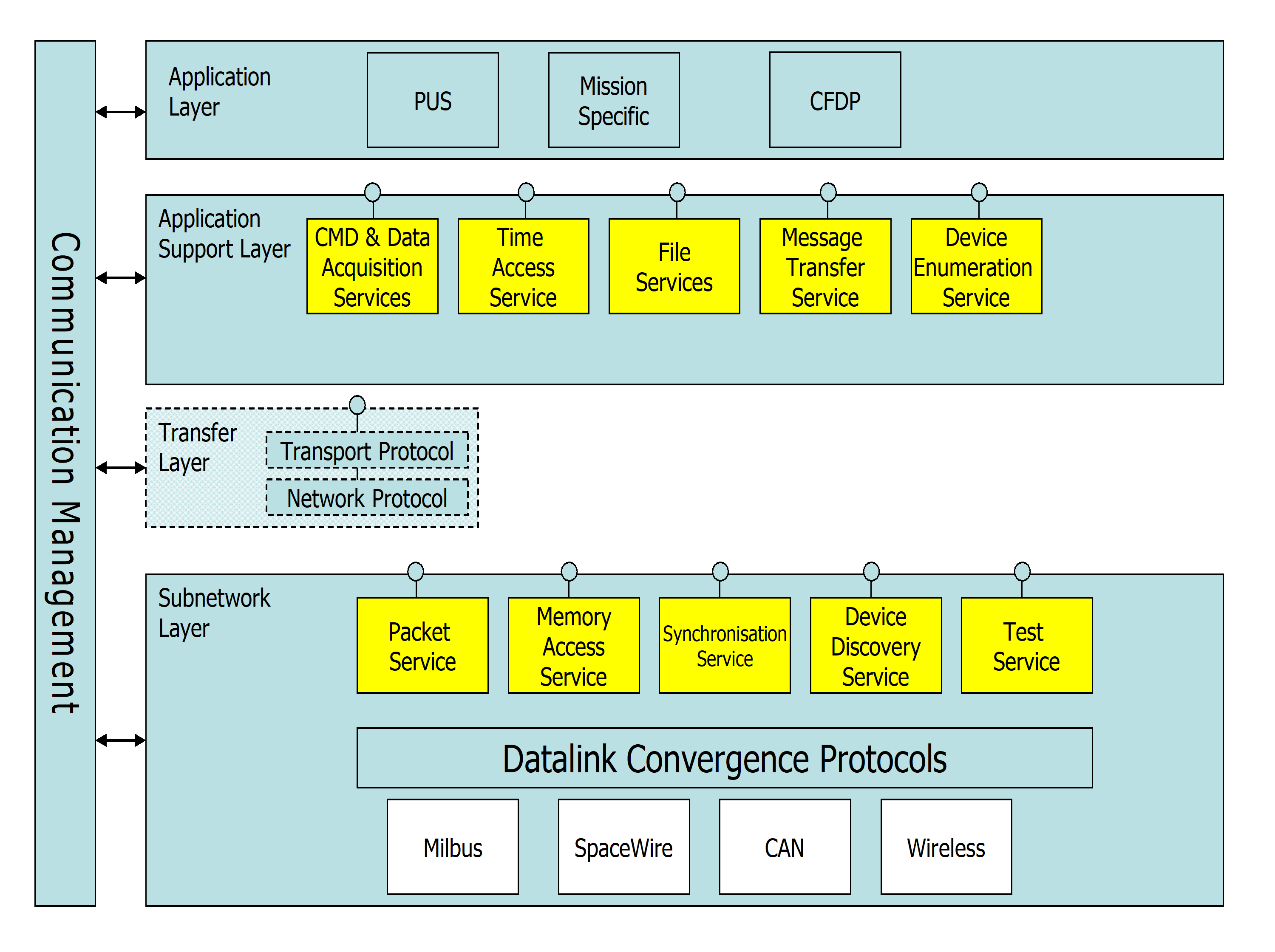 Figure: SOIS communication architecture
The SOIS area of standardisation is intended to provide a common set of communication services which are applicable to all onboard sub-networks. While SOIS defines services it does not define the protocols to implement the services, this is left to expert groups such as ECSS. The services as described in this standard are generally compatible with the SOIS Memory Access Service definition but in some instances the RMAP protocol may include additional capabilities. Annex C provides a detailed mapping between the two sets of services.
Write Service
Initiator
The service primitives associated with this service are:
WRITE.request;
WRITE.confirmation.
WRITE.request
Function
The RMAP Initiator Write service user passes a WRITE.request primitive to the service provider to request that data is written to memory in a target across the SpaceWire network.
Semantics
The WRITE.request primitive provides parameters as follows:
WRITE.request (Target SpaceWire Address, Target Logical Address, Write Command Options, Key, Reply Address, Initiator Logical Address, Transaction Identifier, Extended Address, Memory Address, Data Length, Data)
When Generated
The WRITE.request primitive is passed to the RMAP Initiator Write service provider to request it to write the data into memory in the target.
Effect On Receipt
Receipt of the WRITE.request primitive causes the RMAP Initiator Write service provider to send an RMAP write command to the target.
WRITE.confirmation
Function
The RMAP Initiator Write service provider passes a WRITE.confirmation primitive to the RMAP Initiator Write Service user to confirm that data has been written to memory in a target across the SpaceWire network or to report that an error occurred.
Semantics
The WRITE.confirmation primitive provides parameters as follows:
WRITE.confirmation (Transaction Identifier, Status)
When Generated
The WRITE.confirmation primitive is passed to the RMAP Initiator Write Service user in the initiator when a write reply is received.
Effect On Receipt
The effect on receipt of the WRITE.confirmation primitive on the RMAP Initiator Write Service user in the initiator is undefined.
Additional Comments
The transaction identifier parameter is used by the RMAP Initiator Write service user to identify which RMAP transaction is being confirmed.
Target
The service primitives associated with this service are:
WRITE.authorisation.indication;
WRITE.authorisation.response;
WRITE.data.indication;
WRITE.data.response;
WRITE.indication.
WRITE.authorisation.indication
Function
The RMAP Target Write service provider passes a WRITE.authorisation.indication to the RMAP Target Write service user to ask for authorisation to write to memory in the target.
Semantics
The WRITE.authorisation.indication primitive provides parameters as follows:
WRITE.authorisation.indication (Target Logical Address, Instruction, Key, Initiator Logical Address, Transaction Identifier, Extended Address, Memory Address, Data Length)
When Generated
The WRITE.authorisation.indication primitive is passed from the RMAP Target Write service provider to the RMAP Target Write Service user to request permission to write to memory in the target.
Effect On Receipt
The effect of receipt of the WRITE.authorisation.indication primitive on the RMAP Target Write Service user is for it to issue a WRITE.authorisation.response primitive either authorising or not authorising the memory write operation.
WRITE.authorisation.response
Function
The RMAP Target Write service user passes a WRITE.authorisation.response to the RMAP Target Write service provider to give permission or deny permission to write to memory in the target.
Semantics
The WRITE.authorisation.response primitive provides parameters as follows:
WRITE.authorisation.response (Authorise)
When Generated
The WRITE.authorisation.response primitive is passed from the RMAP Target Write service user to the RMAP Target Write service provider at the target in response to a WRITE.authorisation.indication primitive.
Effect On Receipt
The effect of receipt of the WRITE.authorisation.response primitive on the RMAP Target Write service provider is for it to write data to memory if authorisation is given.
WRITE.data.indication
Function
The RMAP Target Write service provider passes a WRITE.data.indication to the RMAP Write service user to write data to memory in the target.
Semantics
The WRITE.data.indication primitive provides parameters as follows:
WRITE.data.indication (Extended Address, Address, Data Length, Incrementing/Non-incrementing, Data)
When Generated
The WRITE.data.indication primitive is passed from the RMAP Target Write service provider to the RMAP Target Write Service user when permission to write data has been given by the WRITE.authorisation.response primitive.
Effect On Receipt
The effect of receipt of the WRITE.data.indication primitive on the RMAP Target Write service user is for data to be written into memory in the target.
WRITE.data.response
Function
The RMAP Target Write service user passes a WRITE.data.response to the RMAP Write service provided when data has been written to memory in the target.
Semantics
The WRITE.data.response primitive provides parameters as follows:
WRITE.data.response (Status)
When Generated
The WRITE.data.response primitive is passed from the RMAP Target Write service user to the RMAP Target Write service provider when data has been successfully written to target memory or a failure has occurred while writing data to target memory by the WRITE.data.indication primitive.
Effect On Receipt
The effect of receipt of the WRITE.data.response primitive on the RMAP Target Write service provider is for a reply to be sent to the initiator (or other node) if requested and for a WRITE.indication to be passed to the RMAP Target Write service user.
WRITE.indication
Function
The RMAP Target Write service provider passes a WRITE.indication to the RMAP Write service user to indicate that data has been successfully written to memory in the target.
Semantics
The WRITE.indication primitive does not have any parameters.
When Generated
The WRITE.indication primitive is produced when a WRITE.data.response is received from the RMAP Target Write service user with its status parameter indicating that no fault has occurred during the write operation.
Effect On Receipt
The effect of receipt of the WRITE.indication primitive on the RMAP Target Write service user is undefined.
Read Service
Initiator
The service primitives associated with this service are:
READ.request;
READ.confirmation.
READ.request
Function
The RMAP Initiator Read service user passes a READ.request primitive to the RMAP Initiator Read service provider to request that data is read from memory in a target across the SpaceWire network.
Semantics
The READ.request primitive provides parameters as follows:
READ.request (Target SpaceWire Address, Target Logical Address, Read Command Options, Key, Reply Address, Initiator Logical Address, Transaction Identifier, Extended Address, Memory Address, Data Length)
When Generated
The READ.request primitive is passed to the RMAP Initiator Read service provider to request it to read data from memory in the target.
Effect On Receipt
Receipt of the READ.request primitive causes the RMAP Initiator Read service provider to send an RMAP read command to the target.
READ.confirmation
Function
The RMAP Initiator Read service provider passes a READ.confirmation primitive to the RMAP Initiator Read service user to confirm that data has been read from memory in a target across the SpaceWire network and to provide that data to the RMAP Initiator Read service user, or to report that an error occurred.
Semantics
The READ.confirmation primitive provides parameters as follows:
READ.confirmation (Transaction Identifier, Status, Data Length, Data)
When Generated
The READ.confirmation primitive is passed to the RMAP Initiator Read service user when a read reply is received.
Effect On Receipt
The effect on receipt of the READ.confirmation primitive by the RMAP Initiator Read service user is undefined.
Additional Comments
The transaction identifier parameter is used by the RMAP Initiator Read service user to identify which RMAP transaction is being confirmed.
Target
The service primitives associated with this service are:
READ.authorisation.indication;
READ.authorisation.response;
READ.data.indication;
READ.data.response;
READ.indication.
READ.authorisation.indication
Function
The RMAP Target Read service provider passes a READ.authorisation.indication to the RMAP Target Read service user to ask for authorisation to read data from memory in the target.
Semantics
The READ.authorisation.indication primitive provides parameters as follows:
READ.authorisation indication (Target Logical Address, Instruction, Key, Initiator Logical Address, Transaction Identifier, Extended Address, Memory Address, Data Length)
When Generated
The READ.authorisation.indication primitive is passed from the RMAP Target Read service provider to the RMAP Target Read service user at the target to request permission to read data from memory in the target.
Effect On Receipt
The effect of receipt of the READ.authorisation.indication primitive on the RMAP Target Read service user is for it to issue a READ.authorisation.response primitive either accepting or rejecting the read operation.
READ.authorisation.response
Function
The RMAP Target Read service user passes a READ.authorisation.response to the RMAP Target Read service provider to give permission or deny permission to read from memory in the target.
Semantics
The READ.authorisation.response primitive provides parameters as follows:
READ.authorisation.response (Authorise)
When Generated
The READ.authorisation.response primitive is passed from the RMAP Target Read service user to the RMAP Target Read service provider at the target in response to a READ.authorisation.indication primitive.
Effect On Receipt
The effect of receipt of the READ.authorisation.response primitive on the RMAP Target Read service provider is for it to read data from memory by issuing a READ.data.indication primitive.
READ.data.indication
Function
The RMAP Target Read service provider passes a READ.data.indication to the RMAP Target Read service user to read data from memory in the target.
Semantics
The READ.data.indication primitive provides parameters as follows:
READ.data.indication (Extended Address, Address, Data Length, Incrementing/Non-incrementing)
When Generated
The READ.data.indication primitive is passed from the RMAP Target Read service provider to the RMAP Target Read service user at the target when permission to read data has been given by the READ.authorisation.response primitive.
Effect On Receipt
The effect of receipt of the READ.data.indication primitive on the RMAP Target Read service user is for data to be read from memory in the target.
READ.data.response
Function
The RMAP Target Read service provider passes a READ.data.response to the RMAP Target Read service user to provide data read from memory in the target.
Semantics
The READ.data.response primitive provides parameters as follows:
READ.data.response (Status, Data Length, Data)
When Generated
The READ.data.response primitive is passed from the RMAP Target Read service user to the RMAP Target Read service provider after a READ.data.indication has been received.
Effect On Receipt
The effect of receipt of the READ.data.response primitive on the RMAP Target Read service provider is for the data read from memory in the target or an error to be returned to the initiator (or other node).
READ.indication
Function
The RMAP Target Read service provider passes a READ.indication to the RMAP Target Read service user to indicate that data has been successfully read from memory in the target.
Semantics
The READ.indication primitive provides parameters as follows:
READ.indication
When Generated
The READ.indication primitive is passed from the RMAP Target Read service provider to the RMAP Target Read service user at the target when data has been successfully read from memory in the target.
Effect On Receipt
The effect of receipt of the READ.indication primitive on the RMAP Target Read service user is undefined.
Read-Modify-Write Service
Initiator
The service primitives associated with this service are:
RMW.request;
RMW.confirmation.
RMW.request
Function
At the initiator, the RMAP read-modify-write service user passes a RMW.request primitive to the service provider to request that data is read-modify-write memory in a target across the SpaceWire network.
Semantics
The RMW.request primitive provides parameters as follows:
RMW.request (Target SpaceWire Address, Target Logical Address, RMW Command Options, Key, Reply Address, Initiator Logical Address, Transaction Identifier, Extended Address, Memory Address, Data Length, Data, Mask)
When Generated
The RMW.request primitive is passed to the service provider to request it to read-modify-write memory in the target.
Effect On Receipt
Receipt of the RMW.request primitive causes the service provider to send an RMAP read-modify-write command.
RMW.confirmation
Function
At the initiator, the service provider passes a RMW.confirmation primitive to the RMAP read-modify-write service user to confirm that data has been read-modify-written to memory in the target across the SpaceWire network.
Semantics
The RMW.confirmation primitive provides parameters as follows:
RMW.confirmation (Transaction Identifier, Status, Data)
When Generated
The RMW.confirmation primitive is passed to the RMAP read-modify-write service user in the initiator when a RMW reply is received to confirm that data has been read-modify-written to the memory in the target and to provide the data read to the initiator.
Effect On Receipt
Receipt of the RMW.confirmation primitive by the RMAP read-modify-write service user in the initiator is undefined.
Additional Comments
The transaction identifier parameter is used in the initiator to identify which RMAP transaction is being confirmed.
Target
The service primitives associated with this service are:
RMW.authorisation.indication;
RMW.authorisation.response;
RMW.read.data.indication;
RMW.read data.response;
RMW.write.data.indication;
RMW.write.data.response;
RMW.indication.
RMW.authorisation.indication
Function
The RMAP Target RMW service provider passes a RMW.authorisation.indication to the RMAP Target RMW service user to ask for authorisation to read-modify-write memory in the target.
Semantics
The RMW.authorisation.indication primitive provides parameters as follows:
RMW.authorisation.indication (Target Logical Address, Instruction, Key, Initiator Logical Address, Transaction Identifier, Extended Address, Memory Address, Data Length)
When Generated
The RMW.authorisation.indication primitive is passed from the RMAP Target RMW service provider to the RMAP Target RMW service user at the target to request permission to read-modify-write memory in the target.
Effect On Receipt
The effect of receipt of the RMW.authorisation.indication primitive by the RMAP Target RMW service user is for it to issue a RMW.authorisation.response primitive either accepting or rejecting the RMW operation.
RMW.authorisation.response
Function
The RMAP Target RMW service user passes a RMW.authorisation.response to the RMAP Target RMW service provider to give permission or deny permission to read-modify-write memory in the target.
Semantics
The RMW.authorisation.response primitive provides parameters as follows:
RMW.authorisation.response (Authorise)
When Generated
The RMW.authorisation.response primitive is passed from the RMAP Target RMW service user to the RMAP Target RMW service provider at the target in response to a READ.authorisation primitive.
Effect On Receipt
The effect of receipt of the RMW.authorisation.response primitive on the RMAP Target RMW service provider is for it to read memory in the target by issuing a RMW.data.indication primitive.
RMW.read.data.indication
Function
The RMAP Target RMW service provider passes a RMW.read.data.indication to the RMAP Target RMW service user to read data from memory in the target.
Semantics
The RMW.read.data.indication primitive provides parameters as follows:
RMW.read.data.indication (Extended Address, Address, Data Length, Incrementing/Non-incrementing)
When Generated
The RMW.read.data.indication primitive is passed from the RMAP Target RMW service provider to the RMAP Target RMW service user at the target when permission to read data has been given by the RMW.authorisation.response primitive.
Effect On Receipt
The effect of receipt of the RMW.read.data.indication primitive on the RMAP Target RMW service user is for data to be read from memory in the target and returned to the service provider in a RMW.read.data.response.
RMW.read.data.response
Function
The RMAP Target RMW service provider passes a RMW.read.data.response to the RMAP Target RMW service user to provide data read from memory in the target.
Semantics
The READ.data.response primitive provides parameters as follows:
READ.data.response (Status, Data Length, Data)
When Generated
The RMW.read.data.response primitive is passed from the RMAP Target RMW service user to the RMAP Target RMW service provider after a RMW.read.data.indication has been received.
Effect On Receipt
The effect of receipt of the RMW.read.data.response primitive on the RMAP Target RMW service provider is for the data and mask from the RMW command to be passed to the RMAP RMW service user for combining with the data read from memory and writing back into memory.
RMW.write.data.indication
Function
The RMAP Target RMW service provider passes a RMW.write.data.indication to the RMAP RMW service user to modify and write data to memory in the target.
Semantics
The RMW.write.data.indication primitive provides parameters as follows:
RMW.write.data.indication (Extended Address, Address, Data Length, Incrementing/Non-incrementing, Data, Mask)
When Generated
The RMWwrite.data.indication primitive is passed from the RMAP Target RMW service provider to the RMAP Target RMW Service user when data has been read from memory and returned by the RMW.read.data.response primitive.
Effect On Receipt
The effect of receipt of the RMW.write.data.indication primitive on the RMAP Target Write service user is for the data and mask to be combined in some way with the data previously in memory and the new value written into the same memory location in the target.
RMW.write.data.response
Function
The RMAP Target RMW service user passes a RMW.write.data.response to the RMAP RMW service provided when data and mask have been combined with the data previously in memory and the new result written to memory in the target.
Semantics
The RMW.write.data.response primitive provides parameters as follows:
RMW.write.data.response (Status)
When Generated
The RMW.write.data.response primitive is passed from the RMAP Target RMW service user to the RMAP Target RMW service provider when the data and mask have been successfully combined with the data previously in memory and the new result written to target memory or a failure has occurred while combining or writing data to target memory by the RMW.write.data.indication primitive.
Effect On Receipt
The effect of receipt of the RMW.write.data.response primitive on the RMAP Target RMW service provider is for a reply to be sent to the initiator (or other node) if requested and for a RMW.indication to be passed to the RMAP Target RMW service user.
RMW.indication
Function
At the target, the service provider passes a RMW.indication to the RMAP RMW service user after read-modify-writing memory in the target.
Semantics
The RMW.indication primitive does not have any parameters.
When Generated
The RMW.indication primitive is produced when a RMW.write.data.response is received from the RMAP Target RMW service user with its status parameter indicating that no fault has occurred during the read-modify-write operation.
Effect On Receipt
The effect of receipt of the RMW.indication primitive on the RMAP Target RMW service user is undefined.
ANNEX(informative)Mapping to CCSDS SOIS Remote memory access service
The SOIS model for memory access is that there is only one user of that service and that is the user that initiates the service by issuing a WRITE, READ or READ/MODIFY/WRITE request service primitive. This same user is the recipient of the data which derives from a READ request. The memory itself or its manager is not regarded as a user of the service but is a resource embedded in the subnetwork which may be implemented in a number of ways, as can the protocol which accesses it. This provides for an abstract service which is easily implemented at the user end and does not place any unnecessary constraints on the capabilities of the memory being accessed. It does mean, however, that the memory being accessed is part of the subnetwork, not a user of the subnetwork.
The RMAP approach is to provide a conduit where READ, WRITE and READ/MODIFY/WRITE requests and responses are passed transparently through the subnetwork between a user and a memory manager which implements access to the memory. The actual service content provided by the subnetwork is appropriate to a subnetwork providing an encoding for the primitives to be transferred across the subnetwork constraining their utility compared to a simple transparent packet transfer. This allows memory to be accessed which is not embedded in the sub-network, i.e. memory is a user of the subnetwork, not part of the subnetwork.
Figure C-1 and Figure C-2 show the two approaches.
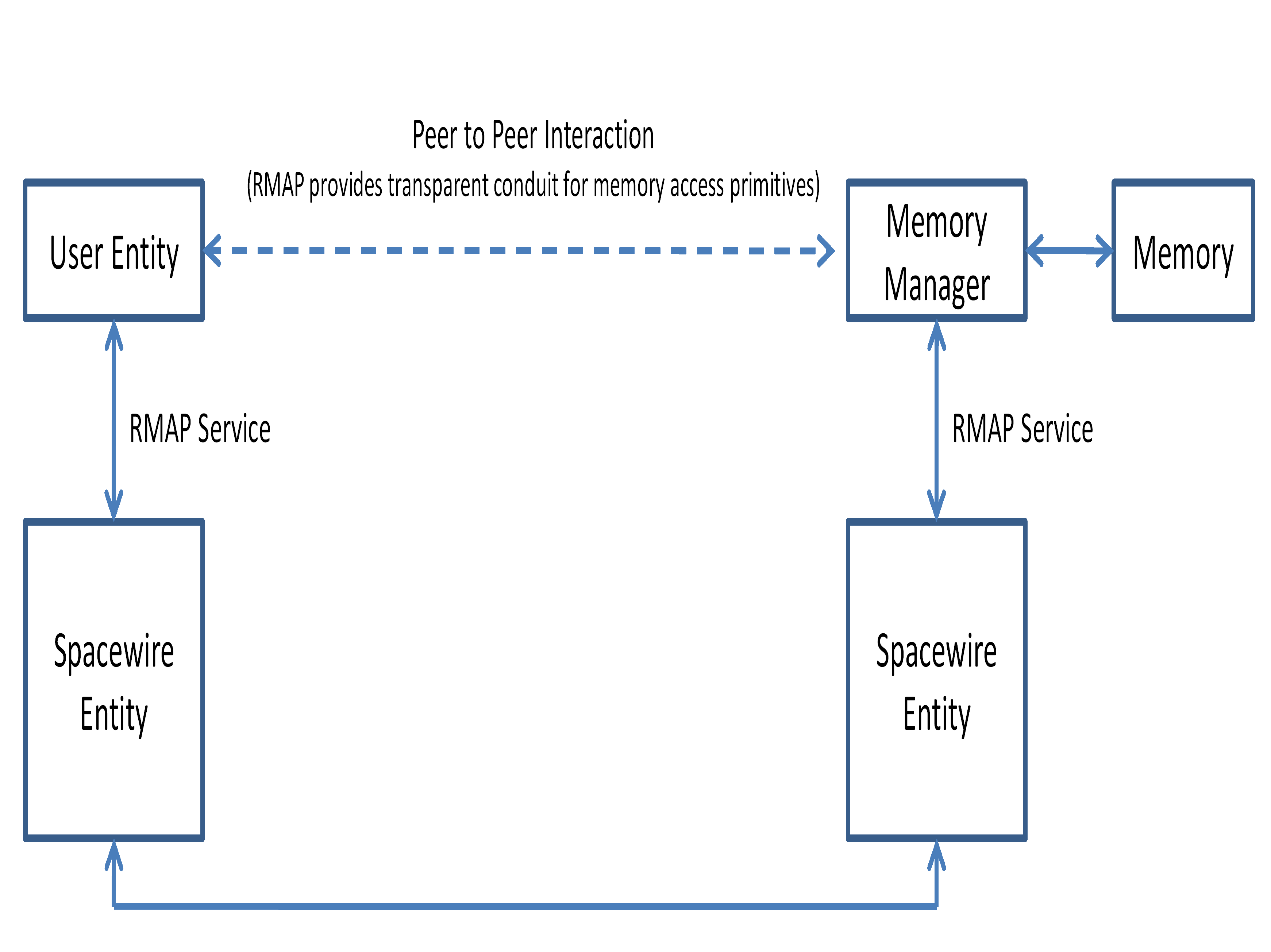 Figure: RMAP model
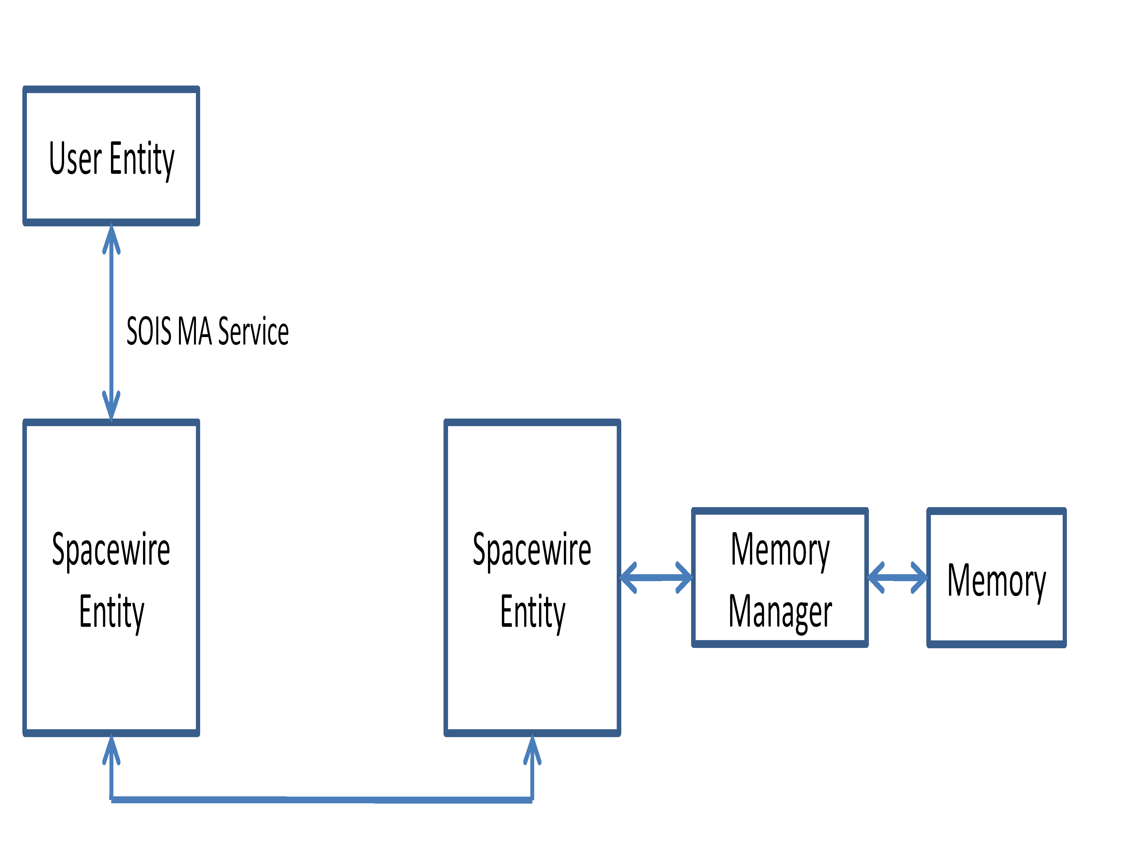 Figure: SOIS model
Note that the RMAP primitives at the memory end have no equivalent in SOIS. Primitives where equivalents do exist have their parameters enumerated. Note also the difference in terminology between confirmations in RMAP and indications in SOIS. This is because the symmetrical nature of RMAP calls for a Request-Indication-Response-Confirm sequence whereas the single ended, asymmetrical nature of the SOIS uses a simple Request-Indication sequence. A Response-Confirm terminology was rejected by SOIS as not reflecting the nature of the interaction at the service interface, which means that memory is a part of the subnetwork and not a user of the subnetwork.
The RMAP READ.confirmation to return the data has a SOIS equivalent in the READ.indication. However the feedback for other requests takes the form of a FAILURE.indication when the user needs to be notified of a failure.
Table C-2 to Table C-7 address equivalence of service parameters for each of the RMAP primitives which have a SOIS equivalent.
The only parameters without equivalents in Table C-2 are the Write Command Options and Key parameters. The connection-orientation implied by the transaction id is not required in SOIS since the explicit details of the memory being accessed is returned in any resulting indication. This is not to say that any implementing protocol can not use the transaction id shorthand, translating to explicit parameters at the service interface.
Table C-3 illustrates this point where the returned MEMORY_ACCESS_FAILURE.indication has explicit memory address details which may have been encoded as a transaction id in the underlying RMAP protocol.
The SOIS parameters in Table C-5 are taken from both the MEMORY_ACCESS_FAILURE.indication and READ.indication primitives.
Table: Comparison of RMAP and Remote Memory Access primitives
|
RMAP Primitive
|
SOIS Equivalent
|
|
WRITE.request (Target SpaceWire Address, Target Logical Address, Write Command Options, Key, Reply Address, Initiator Logical Address, Transaction Identifier, Extended Address, Memory Address, Data Length, Data)
|
WRITE.request (SSNSAP, Destination Address, Memory ID, Start Memory Address, Size, Data)
|
|
WRITE.confirmation (Transaction Identifier, Status)
|
MEMORY_ACCESS_FAILURE.indication (SSNSAP, Destination Address, Memory ID, Start Memory Address, Size, Failure Metadata)
|
|
WRITE.authorisation.indication;
|
No equivalent
|
|
READ.request (Target SpaceWire Address, Target Logical Address, Read Command Options, Key, Reply Address, Initiator Logical Address, Transaction Identifier, Extended Address, Memory Address, Data Length)
|
READ.request (SSNSAP, Destination Address, Memory ID, Start Memory Address, Size)
|
|
READ.confirmation (Transaction Identifier, Status, Data Length, Data)
|
READ.indication (SSNSAP, Destination Address, Memory ID, Start Memory Address, Size, Data)
|
|
READ.authorisation.indication;
|
No equivalent
|
|
RMW.request (Target SpaceWire Address, Target Logical Address, RMW Command Options, Key, Reply Address, Initiator Logical Address, Transaction Identifier, Extended Address, Memory Address, Data Length, Data, Mask)
|
Read/Modify/Write.request (SSNSAP, Destination Address, Memory ID, Memory Address, Size, Mask, Data)
|
|
RMW.confirmation (Transaction Identifier, Status, Data)
|
MEMORY_ACCESS_FAILURE.indication (SSNSAP, Destination Address, Memory ID, Start Memory Address, Size, Failure Metadata)
|
|
RMW.authorisation.indication;
|
No equivalent
|
Table: WRITE.request parameters
|
RMAP Parameters
|
SOIS Equivalent
|
|
Target SpaceWire Address, Target Logical Address
|
Destination Address
|
|
Write Command Options, Key,
|
|
|
Reply Address, Initiator Logical Address,
|
SSNSAP
|
|
Transaction Identifier
|
SSNSAP, Destination Address, Memory ID, Start Memory Address, Size
|
|
Extended Address, Memory Address
|
Memory ID, Start Memory Address
|
|
Data Length
|
Size
|
|
Data
|
Data
|
Table: WRITE.confirmation parameters
|
RMAP Parameters
|
SOIS Equivalent
|
|
Transaction Identifier
|
SSNSAP, Destination Address , Memory ID, Start Memory Address, Size
|
|
Status
|
Failure Metadata
|
Table: READ.request parameters
|
RMAP Parameters
|
SOIS Equivalent
|
|
Target SpaceWire Address, Target Logical Address
|
Destination Address
|
|
Read Command Options, Key,
|
|
|
Reply Address, Initiator Logical Address,
|
SSNSAP
|
|
Transaction Identifier
|
SSNSAP, Destination Address, Memory ID, Start Memory Address, Size
|
|
Extended Address, Memory Address
|
Memory ID, Start Memory Address
|
|
Data Length
|
Size
|
Table: READ.confirmation parameters
|
RMAP Parameters
|
SOIS Equivalent
|
|
Transaction Identifier
|
SSNSAP, Destination Address , Memory ID, Start Memory Address, Size
|
|
Status
|
Failure Metadata
|
|
Data Length
|
Size
|
|
Data
|
Data
|
Table: RMW.request parameters
|
RMAP Parameters
|
SOIS Equivalent
|
|
Target SpaceWire Address, Target Logical Address
|
Destination Address
|
|
RMW Command Options, Key,
|
|
|
Reply Address, Initiator Logical Address,
|
SSNSAP
|
|
Transaction Identifier
|
SSNSAP, Destination Address, Memory ID, Start Memory Address, Size
|
|
Extended Address, Memory Address
|
Memory ID, Start Memory Address
|
|
Data Length
|
Size
|
|
Data
|
Data
|
|
Mask
|
Mask
|
Table: RMW.confirmation parameters
|
RMAP Parameters
|
SOIS Equivalent
|
|
Transaction Identifier
|
SSNSAP, Destination Address , Memory ID, Start Memory Address, Size
|
|
Status
|
Failure Metadata
|
|
|
Size
|
|
Data
|
Data
|
Bibliography
|
ECSS-ST-S-00
|
ECSS system - Description, implementation and general requirements
|
|
http://www.spacewire.esa.int
|
SpaceWire website
|