
Space engineering
Ground systems and operations
Foreword
This Standard is one of the series of ECSS Standards intended to be applied together for the management, engineering and product assurance in space projects and applications. ECSS is a cooperative effort of the European Space Agency, national space agencies and European industry associations for the purpose of developing and maintaining common standards. Requirements in this Standard are defined in terms of what shall be accomplished, rather than in terms of how to organize and perform the necessary work. This allows existing organizational structures and methods to be applied where they are effective, and for the structures and methods to evolve as necessary without rewriting the standards.
This Standard has been prepared by the ECSS-E-ST-70C Working Group, reviewed by the ECSS Executive Secretariat and approved by the ECSS Technical Authority.
Disclaimer
ECSS does not provide any warranty whatsoever, whether expressed, implied, or statutory, including, but not limited to, any warranty of merchantability or fitness for a particular purpose or any warranty that the contents of the item are error-free. In no respect shall ECSS incur any liability for any damages, including, but not limited to, direct, indirect, special, or consequential damages arising out of, resulting from, or in any way connected to the use of this Standard, whether or not based upon warranty, business agreement, tort, or otherwise; whether or not injury was sustained by persons or property or otherwise; and whether or not loss was sustained from, or arose out of, the results of, the item, or any services that may be provided by ECSS.
Published by: ESA Requirements and Standards Division
ESTEC, ,
2200 AG Noordwijk
The
Copyright: 2008 © by the European Space Agency for the members of ECSS
Change log
|
ECSS-E-70 Part 1A
|
First issues
|
|
ECSS-E-70B
|
Never issued
|
|
ECSS-E-ST-70C
|
The present version (ECSS-E-ST-70C) is the evolution of ECSS-E-70 Part 1A “Ground systems and operations - Principles and requirement” and ECSSE70 Part 2A “Ground systems and operations - Document requirements definition”, which are published now together in the present document.
|
Introduction
Ground systems and operations are key elements of a space system and play an essential role in achieving mission success. Mission success is defined here as the achievement of the target mission objectives as expressed in terms of the quantity, quality and availability of delivered mission products and services within a given cost envelope.
Mission success requires successful completion of a long and complex process covering the definition, design, production, verification, validation, post-launch operations and post operational activities, involving both ground segment and space segment elements. It involves technical activities, as well as human and financial resources, and encompasses the full range of space engineering disciplines. Moreover it necessitates a close link with the design of the space segment in order to ensure proper compatibility between these elements of the complete space system.
Scope
Within the framework of the overall engineering standards for space missions, this Standard contains the basic rules, principles and requirements applied to the engineering of the ground segment and mission operations, which form an integral part of the overall system implementing a space project.
This Standard also addresses the relationships between a customer and the ground segment supplier (GSS) and a customer and the operations supplier (OS).
The following topics are not considered:
Ground systems (e.g. EGSE) and operations to support space segment verification which are covered within ECSS-E-ST-10-02.
The launch segment and its operations.
This Standard has the following structure:
definition of the ground segment and operations domain;
requirements on ground segment engineering, i.e. the tasks required to design, implement and maintain a ground segment;
requirements on operations engineering, i.e. the tasks required to prepare and carry out operations of a space project;
identification of the relationships between the ground segment engineering and operations engineering processes and the space project lifecycle as defined in ECSS-M-ST-10.
This Standard may be tailored for the specific characteristics and constraints of a space project in conformance with ECSS-S-ST-00.
Normative references
The following normative documents contain provisions which, through reference in this text, constitute provisions of this ECSS Standard. For dated references, subsequent amendments to, or revision of any of these publications do not apply, However, parties to agreements based on this ECSS Standard are encouraged to investigate the possibility of applying the more recent editions of the normative documents indicated below. For undated references, the latest edition of the publication referred to applies.
|
ECSS-S-ST-00-01
|
ECSS system – Glossary of terms
|
|
ECSS-E-ST-10
|
Space engineering – System engineering general requirements
|
|
ECSS-E-ST-10-02
|
Space engineering – Verification
|
|
ECSS-E-ST-10-06
|
Space engineering - Technical specification
|
|
ECSS-E-ST-40
|
Space engineering – Software general requirements
|
|
ECSS-M-ST-40
|
Space project management – Configuration and information management
|
|
ECSS-M-ST-70
|
Space project management - Integrated logistic support
|
|
ECSS-Q-ST-10-09
|
Space product assurance - Nonconformance control system
|
|
ECSS-Q-ST-80
|
Space product assurance - Software product assurance
|
Terms, definitions and abbreviated terms
Terms defined in other standards
For the purpose of this Standard, the terms and definitions from ECSSSST0001 apply.
For the purpose of this Standard, the following terms and definitions from ECSSEST10 apply:
system engineering
For the purpose of this Standard, the terms and definitions from ECSSEST1002 apply:
inspection
test
Terms specific to the present standard
entity
combination of ground systems and the associated personnel or operations organization
ground segment operations
activities related to the operations planning, execution and evaluation of the ground segment (or subsets thereof)
ground segment
ground systems necessary for the preparation or execution of mission operations
ground segment customer
party responsible for the procurement of the ground segment
The ground segment customer interfaces with the ground segment supplier through a customer-supplier relationship.
ground segment supplier
party responsible for the supply of the ground segment
ground system
integrated set of ground functions used to support the preparation activities leading up to mission operations or the conduct of mission operations itself
incident
in provision of a service, an enquiry, an observation or an anomaly, which relates to, causes or can cause, an interruption to, or a reduction in, the quality of the service
mission
specific objectives to be achieved by a space system as characterized by its expected products in terms of quantity, quality and availability
mission exploitation
activity consisting of the planning, generation, utilization and evaluation of the products of the space mission
mission information
information pertaining to the space segment and ground segment during the pre–launch and post–launch phases
- 1 It typically includes space segment and ground segment design and operations characteristics, space segment and ground segment test and operations procedures, telemetry and telecommand characteristics.
- 2 It is composed of source data originating from the operations customer and ground segment supplier and derived data produced by the operations teams.
mission operations
activities related to the operations planning, execution and evaluation of the combined space segment and ground segment during phases E and F of a space project
mission operations data
subset of the mission information used to execute the in–orbit operations
For example: Operations procedures, operations rules and monitoring and control databases.
mission products
products and services delivered by the space system
For example: Communications services, science data.
operational validation
test activities whose objective is to establish the readiness of the complete ground segment, including mission operations data, and operations personnel to support the space mission in–orbit by means of simulations and rehearsals
The completion of the operational validation process results in a qualified ground segment.
operations customer
party responsible for the procurement of the operations of the space segment and ground segment
- 1 The operations customer interfaces with the operations supplier through a customer-supplier relationship.
- 2 The operations customer and the ground segment customer are usually the same entity.
operations supplier
party responsible for the preparation and execution of space segment operations and ground segment operations
space segment operations
activities related to the operations planning, execution and evaluation of the space segment (or subsets thereof) when in orbit
synthetic parameter
parameter derived from telemetry and other data via an algorithm
Abbreviated terms
For the purpose of this Standard, the abbreviated terms from ECSS-S-ST-00-01 and the following apply:
|
Abbreviation
|
Meaning
|
|
ABM
|
apogee boost motor
|
|
AIT
|
assembly, integration and test
|
|
AOCS
|
attitude and orbit control subsystem
|
|
ATV
|
automated transfer vehicle
|
|
CCSDS
|
Consultative Committee for Space Data Systems
|
|
CFISRD
|
customer furnished items and services requirements document
|
|
COTS
|
commercial off–the–shelf
|
|
CRR
|
customer requirements review
|
|
DFT
|
data flow test
|
|
DRD
|
document requirements definition
|
|
EEPROM
|
electrically erasable programmable read-only memory
|
|
EGSE
|
electrical ground support equipment
|
|
ELR
|
end-of-life review
|
|
EM
|
engineering model
|
|
FAT
|
factory acceptance testing
|
|
FDIR
|
failure detection, isolation and recovery
|
|
FM
|
flight model
|
|
FMEA
|
failure modes and effects analysis
|
|
FMECA
|
failure modes, effects and criticality analysis
|
|
FQR
|
flight qualification review
|
|
FRR
|
flight readiness review
|
|
FS
|
functional specification
|
|
FTA
|
fault tree analysis
|
|
GEO
|
geostationary orbit
|
|
GS
|
ground segment
|
|
GSAITP
|
ground segment AIT plan
|
|
GSC
|
ground segment customer
|
|
GSCDR
|
ground segment critical design review
|
|
GSCRD
|
ground segment customer requirements document
|
|
GSDDF
|
ground segment design definition file
|
|
GSDJF
|
ground segment design justification file
|
|
GSEP
|
ground segment engineering plan
|
|
GSPDR
|
ground segment preliminary design review
|
|
GSQR
|
ground segment qualification review
|
|
GSRD
|
ground segment requirements document
|
|
GSSRR
|
ground segment system requirements review
|
|
GSS
|
ground segment supplier
|
|
GSVP
|
ground segment verification plan
|
|
HCI
|
human–computer interaction
|
|
I/F
|
Interface
|
|
I/O
|
input/output
|
|
ICD
|
interface control document
|
|
IOOR
|
in–orbit operations review
|
|
ISS
|
International Space Station
|
|
LAN
|
local area network
|
|
LEO
|
low-Earth orbit
|
|
LEOP
|
launch and early orbit phase
|
|
LIT
|
listen-in test
|
|
LS
|
logistic support
|
|
LSP
|
logistics support plan
|
|
MAR
|
mission analysis report
|
|
MCR
|
mission close–out review
|
|
MDD
|
mission description document
|
|
MOCD
|
mission operations concept document
|
|
MOP
|
mission operations plan
|
|
MRT
|
mission readiness tests
|
|
OAR
|
operations anomaly report
|
|
OBDH
|
on-board data handling
|
|
OBSM
|
on-board software maintenance
|
|
OBSW
|
on-board software
|
|
OC
|
operations customer
|
|
OCRD
|
operations customer requirements document
|
|
OEP
|
operations engineering plan
|
|
OPS
|
operations
|
|
OQR
|
operational qualification review
|
|
ORR
|
operational readiness review
|
|
OS
|
operations supplier
|
|
OTP
|
operations training plan
|
|
OVP
|
operational validation plan
|
|
PCC
|
payload control centre
|
|
PDR
|
preliminary design review
|
|
PLUTO
|
procedure language for users in test and operations
|
|
PROM
|
programmable read-only memory
|
|
PRR
|
preliminary requirements review
|
|
PUS
|
packet utilization standard
|
|
RAM
|
random access memory
|
|
REP
|
report
|
|
RF
|
radio frequency
|
|
ROM
|
read-only memory
|
|
SGICD
|
space–to–ground interface control document
|
|
SPEC
|
specification
|
|
SPR
|
software problem report
|
|
SSC
|
space system customer
|
|
SSORD
|
space segment operability requirements document
|
|
SSS
|
space segment supplier
|
|
SSM
|
space system model
|
|
SSUM
|
space segment user manual
|
|
SVT
|
system validation test
|
|
TS
|
technical specification
|
|
TT&C
|
telemetry, tracking and command
|
Ground segment and operations domain
Overview
The domain of ECSS-E-ST-70 is shown in Figure 41 and is composed of two main components:
The ground segment comprising all ground systems that are used to support the preparation activities leading up to mission operations, the conduct of operations themselves and all post–operational activities.
Operations organizations comprising the human resources undertaking the mission preparation and mission operations tasks.
An entity is the combination of an operations organization and associated ground systems.
Examples:
- A control centre from which the elements of an operations organization control an element of the mission such as a space segment or ground station. In the case of space segment control, an element of the operations organization is the mission control team that uses the operations control system.
- A ground station and its operations and maintenance staff.
Operations organization
Operations organizations are comprised of teams. The composition, responsibilities and management of these teams varies between organizations and over time. The following personnel are typically involved in the teams:
Operations managers;
Spacecraft operators (astronauts, operations engineers, spacecraft analysts, spacecraft controllers);
Payload operators (e.g. payload specialists, PIs);
planners;
Flight dynamics engineers;
Ground systems operators;
exploitation personnel (e.g. scientific/algorithm experts, end-user community liaison staff, product generation support staff);
Ground systems maintenance engineers.
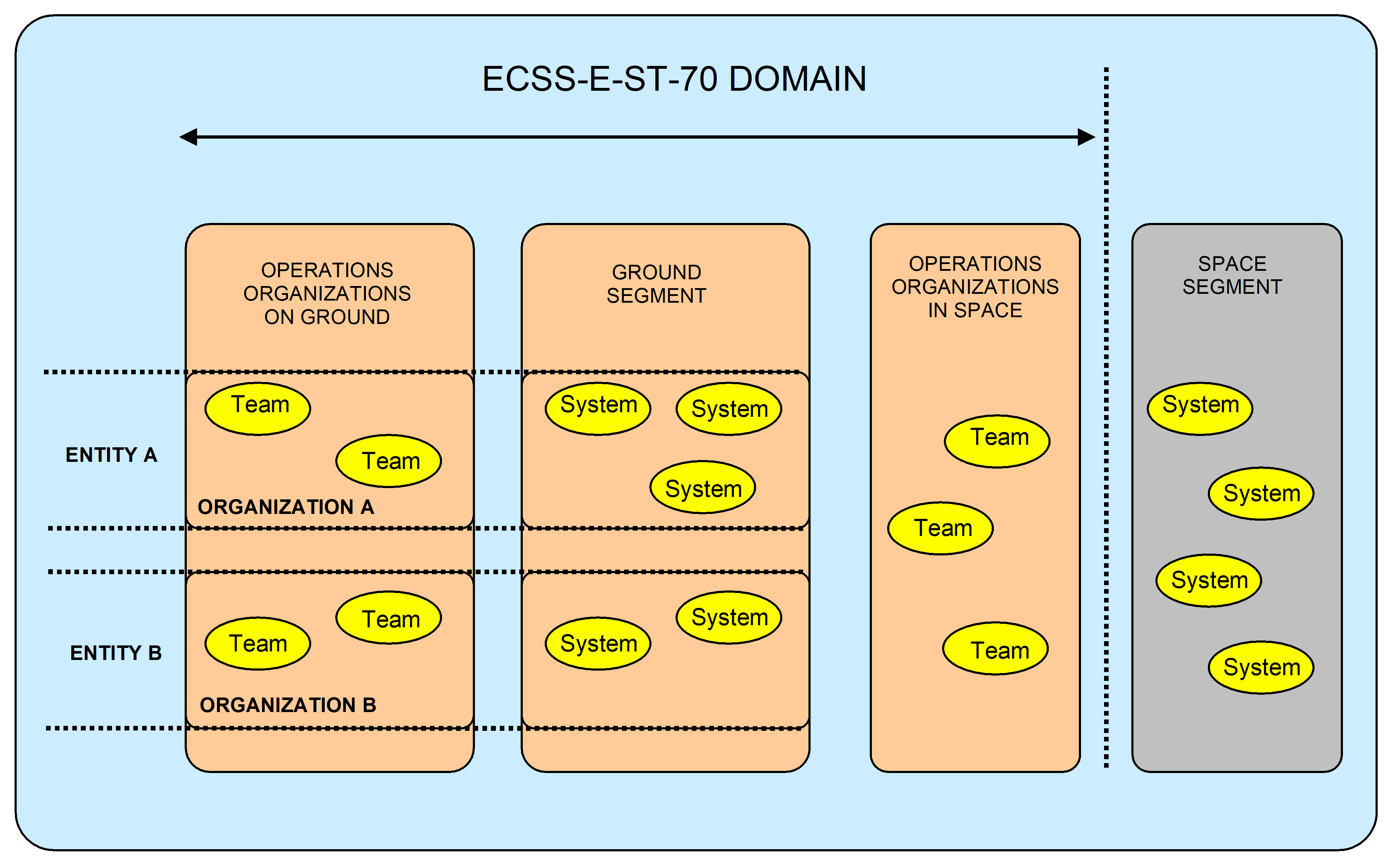 Figure 41: The ECSS-E-ST-70 domain
Ground systems
Introduction
The ground segment, as shown in Figure 42, typically consists of the following top-level systems which can be distributed across various centres depending on the chosen ground segment architecture:
operations system;
Payload operations and data system;
Ground station system;
Ground communications system.
These top-level systems are further broken down during the design process.
operations system
The mission operations system typically supports the following:
analysis;
Operations preparation;
Simulation;
Mission planning and scheduling;
Monitoring and control;
Flight dynamics;
On-board software maintenance and management;
Data archiving;
User services;
Data product delivery;
Performance analysis and reporting;
Configuration management (space segment, ground segment, mission information);
System maintenance.
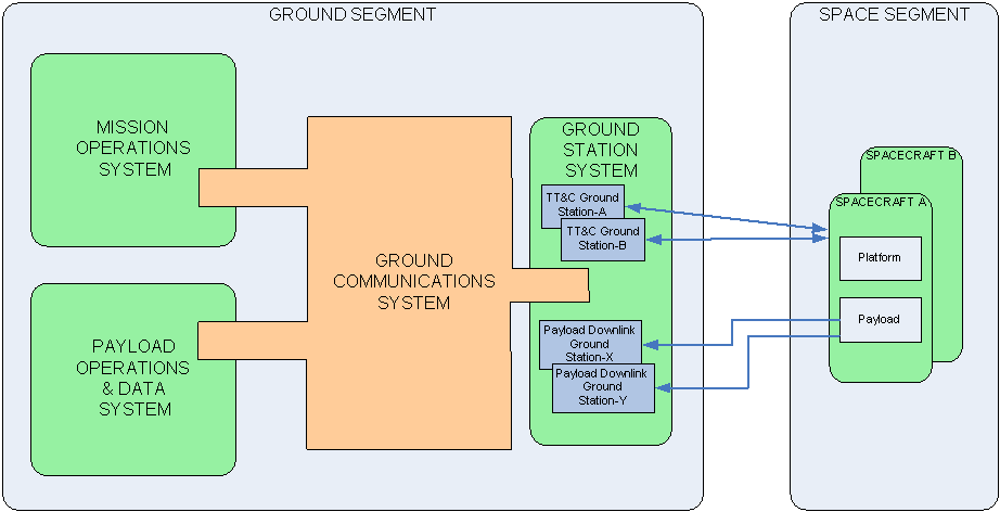 Figure 42: Ground segment systems
Payload operations and data system
The payload operations and data system is used to exploit the mission products and typically supports:
Payload operations analysis;
Payload operations preparation;
Simulation;
Payload operations planning and scheduling;
Payload operations control;
Payload data processing;
Payload data archiving;
User services;
Data product delivery;
Performance analysis and reporting;
Algorithm tuning and development, verification and validation;
System maintenance.
Ground station system
The ground station system provides the physical link with the space segment while in–orbit. The following are supported, where applicable:
Telemetry reception, storage and distribution;
Telecommand transmission;
Tracking, ranging, Doppler and meteorological data acquisition;
Station monitoring and control;
Time management;
Network management and scheduling;
Data distribution;
System maintenance.
Ground communications system
The ground communications system provides the interconnections between systems, for example between ground stations and mission control facilities. The following are supported, where applicable:
Data distribution;
Voice and video communication;
System maintenance.
Engineering processes
Two major engineering disciplines are involved in ground systems procurement and operations:
Operations engineering which encompasses activities involved in the preparation and execution of mission operations;
Ground segment engineering which comprises the activities involved in the definition, design, production, AIT and verification and maintenance of the ground segment for a specific mission.
These are presented as separate process chains, however there are many links between them which imply close cooperation between the two disciplines starting at the definition/requirements phase. Both engineering disciplines contribute to the definition of requirements for the space segment as well as to the review of the on-board design.
Critical areas
In order to cost–effectively ensure mission success, this Standard covers the coordination established during the phases of the space system project, between space and ground segment, and between ground segment entities, as these are often under different responsibilities. Critical areas include:
Definition of overall mission concepts at space system level with due consideration being given to ground segment and operations aspects;
Spacecraft operability and maintainability;
Adequacy of inputs delivered by the operations customer (OC) to the mission operations teams;
End–to–end validation of the complete space system;
Re–use, to the maximum possible extent, of space segment operations knowledge and data (e.g. telemetry and telecommand definitions procedures) between space segment design, space segment AIT and mission operations;
Commonality between processes and services of the ground segment and also between space segment AIT and mission operations;
Security and safety;
Ground and space-to-ground communications design and cost.
These areas are taken into account in the definition of the ground segment engineering and operations engineering activities, as appropriate.
Operations engineering
Overview
Figure 51 shows the main operations engineering processes, which are:
Requirements analysis and concept development;
operations data production;
operations data validation;
Operations teams build-up and training;
Operational validation;
Operational configuration management;
Operations execution (LEOP, commissioning, routine phase operations);
Space segment disposal operations.
Operations engineering covers operation of both the space segment and ground segment.
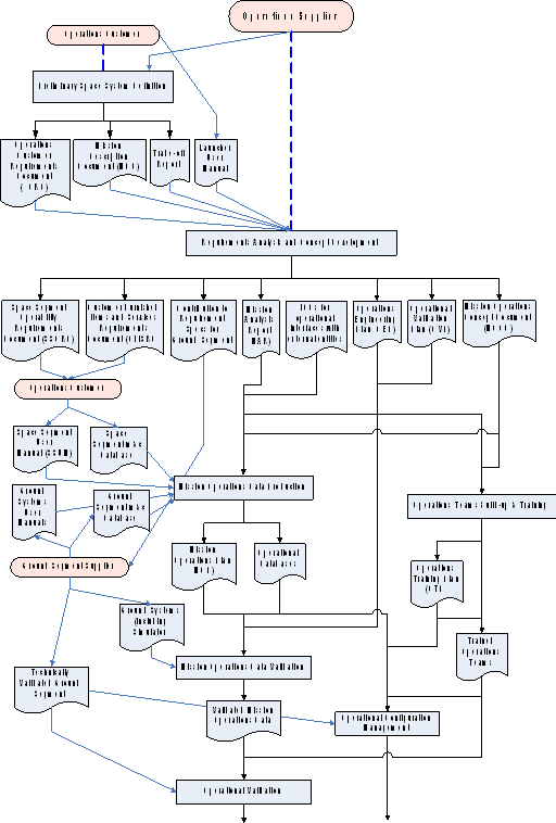 PART 1/2
Figure 51: Schematic of operations engineering process
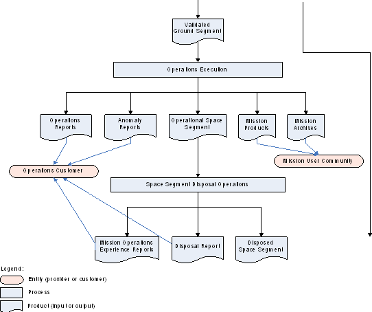 PART 2/2
Figure 51: Schematic of operations engineering process (Cont’d)
Requirements analysis and concept development
Inputs
The inputs to the requirements analysis and concept development process shall be the ones specified in Table 51.
- 1 The production of the OCRD, MDD and trade-off report are space system level phase 0 activities for which both ground segment engineering and operations engineering expertise is needed.
- 2 The mission description document contains the mission analysis, system description and operations scenarios (for each considered mission concept).
- 3 The trade-off report provides a summary of the different mission concepts considered at space system level, the criteria used to assess them and the justification for the selected solution.
- 4 The mission description document and trade-off report are defined in ECSS-E-ST-10.
Table 51 Inputs to the requirements analysis and concept development process
|
ID
|
Title
|
Mnemonic
|
Provider
|
|
1
|
Operations customer requirements document
|
OCRD
|
Operations customer
|
|
2
|
description document
|
MDD
|
Operations customer
|
|
3
|
Trade-off report
|
|
Operations customer
|
|
4
|
Launcher user manual
|
|
Operations customer
|
The contents of the operations customer requirements document (OCRD) shall be in conformance with Annex A.
- 1 The OCRD corresponds to the “Initial technical specification” (TS) of ECSS-E-ST-10-06, tailored for the operations domain.
- 2 The operations customer consults with the end-user community to ensure that its requirements are appropriately captured in the OCRD.
Process description
analysis
analysis shall characterize the following aspects:
- Launcher constraints.
- Ground station characteristics.
- Spacecraft constraints.
- Mission-specific constraints.
For example: Station-keeping window for geostationary spacecraft, orbit phasing for low-Earth-orbiting (LEO) spacecraft).
- Payload constraints.
- Data flow constraints.
- 1 analysis provides information about how the mission is flown, in sufficient detail for the planning and execution of mission operations.
- 2 analysis also provides input to the spacecraft and mission design.
- 3 The mission analysis process is carried out in cooperation with the space segment supplier's operations team.
The mission analysis shall supply the following information: - Launch window prediction.
- Spacecraft and launch vehicle separation sequence.
- Launch target orbit.
- Positioning or manoeuvring strategy.
- Orbit determination concept and navigation analysis (station selection, data types, tracking schedule).
- Schedule of operational events (covering both nominal scenarios and planned contingencies), from which the detailed operations schedules used to execute the mission are derived.
- Ground station coverage.
- Detailed analysis of high risk sequences.
- Risk of interference with spacecraft already in operation.
- Delta-V budget.
- Impact of space environment on operational sequences.
For example: Sensor blinding, eclipses.
- Payload operations strategy.
- Data circulation scheme. The output of the mission analysis shall be the mission analysis report (MAR) in conformance with Annex B.
Operational analysis and concept development
Operational analysis shall consist of the following:
- Assess the consistency and completeness of the customer requirements.
- Assess the operational feasibility of the mission.
- Identify the main drivers for the development of the mission operations concept.
- Define the mission operations concept and derive requirements for the corresponding operations engineering activities and the supporting ground segment (and any necessary in-orbit infrastructure).
- Contribute to the definition of ground segment internal and external interfaces (and any necessary in-orbit infrastructure). The output of these tasks shall be the mission operations concept document (MOCD) in conformance with Annex C.
Operational interfaces definition
Space segment operability requirements shall be identified to ensure that the space segment can be operated during nominal situations and foreseeable contingency situations, in accordance with the mission requirements and objectives in terms of the quantity, quality and availability of mission products.
The space segment operability requirements identified in clause 5.2.2.3a. shall be compiled in the space segment operability requirements document (SSORD).
ECSS-E-ST-70-11 defines space segment operability requirements for various classes of space missions. The SSORD is a tailored version of this standard.
The on-board mission operations services shall be defined, in consultation with the operations customer, together with their capability sets and the corresponding service requests (telecommands) and service reports (telemetry).
ECSS-E-ST-70-41 defines a number of standard on-board mission operations services covering the requirements of various classes of space missions and can be tailored for this purpose. Alternatively, a standalone document can be produced defining the services deployed for the mission or they can be included in the SGICD.
Operational interfaces with external entities shall be identified and documented in “operational ICDs” including:
- Information on points of contact.
- Type and availability of services that can be expected on both sides of the interface.
- Format and method of data exchanges.
Operational ICDs shall subsequently form part of the MOP (see clause 5.3).
Deliverable items and support services from the OC throughout the ground segment life cycle shall be identified in the Customer Furnished Items and Services Requirements Document (CFISRD) including requirements for the delivery of the following: - Space segment documents and information used in the implementation of the ground segment and subsequent mission operations.
For example: Space segment user manual (SSUM), space segment detailed design documents, spacecraft monitoring and control database.
- Procedures applicable for in-orbit operations validated during the space segment AIT programme.
- Provision of representative space segment telemetry and telecommand data samples (including payload data).
- Provision of suitcase for testing compatibility between space segment TT&C and ground stations.
- Access to the space segment when on ground, for the validation of the compatibility between the ground and space segments.
- Support to, or supply of, the operational simulator and space segment models, along with test and training tools used for the validation of the ground segment.
- Provision of on-board software and associated documentation.
- Data processing tools to be incorporated into the mission operations system.
For example, data decommutation for mission-specific telemetry encoding, derived parameter algorithms.
- Software development environment, validation tools such as validation test benches, documentation and engineering support used for the maintenance of the on-board software during operations execution.
- Provision of space segment engineering support for the ground segment design phases (in particular testing and support to ground segment reviews) and during phases E and F.
- Provision of space segment engineering support for the in–orbit control of the mission during designated phases.
- Provision of site infrastructure.
- 1 For example, accommodation of operations staff when working at payload or space segment suppliers’ sites.
- 2 The OC is the conduit to the operations supplier (OS) for external deliverable items and services even though these can originate from other parties e.g. the space segment supplier (SSS).
The contents of the CFISRD shall be in conformance with Annex J.
Contributions from both operations engineering and ground segment engineering expertise shall be provided for the definition of space segment interfaces.
Operations engineering plan production
An operations engineering plan (OEP) shall be developed describing the following:
- The detailed schedule for the production and validation of mission operations data.
- The mission operations team organisation for both the operations preparation and operations execution phases.
- The recruitment profile for the mission operations team, showing how staff are phased-in (and out) and identifying any potential time-sharing or role-sharing with other concurrent missions.
- The contents of the OEP shall be in conformance with Annex D.
- 1 The purpose of the OEP is to provide all the technical information needed to cost the operations manpower and to provide the basis for the timely recruitment of the mission operations team.
- 2 Where the ground segment supplier and operations supplier belong to the same organization, the ground segment engineering plan (GSEP, see clause 6.2.2.3) and the OEP can be combined into a single document.
Contribution to ground segment and ground systems requirements specification
User requirements shall be produced for the ground segment and for each ground segment system.
- 1 The partitioning of the ground segment into ground systems is part of the ground segment design engineering process (see clause 6.2.2.3)
- 2 These requirements are an elaboration of, or are complementary to, those contained in the OCRD
User requirements shall be produced for tools to be used for system and mission operations data validation and training and simulation purposes.
User requirements shall address operational aspects including the following: - The functionality and performance of the ground systems in order to plan, schedule, monitor and control, and evaluate the performance of the space and ground segments.
- Automation requirements reflecting the operations concept and staffing profiles foreseen for different mission phases.
- Operations centralization and decentralization aspects.
For example, remote monitoring and control.
- User management.
For example, login, privileges.
- HCI considerations.
Operational validation plan production
An operational validation plan (OVP) shall be produced for the operational validation of the ground segment systems and the mission operations data.
The OVP shall cover:
- Test preparation activities.
- Technical and managerial resources used for execution of the tests.
- Test strategies, methods and scenarios.
- Test pass or fail criteria.
- Post-test activities.
For example, reporting, handling of non-conformances.
The contents of the OVP shall be in conformance with Annex F.
Outputs
The outputs of the requirements analysis and concept development process shall be the ones specified in Table 52.
Table 52: Outputs of the requirements analysis and concept development process
|
ID
|
Title
|
Mnemonic
|
Producer
|
|
1.
|
analysis report
|
MAR
|
Operations supplier
|
|
2.
|
operations concept document
|
MOCD
|
Operations supplier
|
|
3.
|
Space segment operability requirements document
|
SSORD
|
Operations supplier
|
|
4.
|
Customer furnished items and services requirements document
|
CFISRD
|
Operations supplier
|
|
5.
|
ICDs for operational interfaces with external entities
|
|
Operations supplier
|
|
6.
|
Operations engineering plan
|
OEP
|
Operations supplier
|
|
7.
|
User requirements for the ground segment and the ground segment systems including validation, training and simulation tools (part of the corresponding requirements specifications)
|
|
Operations supplier
|
|
8.
|
Operational validation plan
|
OVP
|
Operations supplier
|
operations data production
Inputs
The inputs to the mission operations data production process shall be the ones specified in Table 53.
The space segment user manual (SSUM) contents shall conform to Annex E.
The SSUM includes information used for the operation of the space segment and essential inputs for the design of the ground segment.
Table 53: Inputs to the mission operations data production process
|
ID
|
Title
|
Mnemonic
|
Provider
|
|
1
|
analysis report
|
MAR
|
Operations supplier
|
|
2
|
operations concept document
|
MOCD
|
Operations supplier
|
|
3
|
ICDs for operational interfaces with external entities
|
|
Operations supplier
|
|
4
|
Space segment user manual
|
SSUM
|
Operations customer
|
|
5
|
Space segment detailed design documents
|
|
Operations customer
|
|
6
|
Space segment monitoring and control database
|
|
Operations customer
|
|
7
|
Ground systems user manuals
|
|
Ground segment supplier
|
|
8
|
Ground segment monitoring and control database
|
|
Ground segment supplier
|
|
NOTE Some inputs to operations engineering processes come from ground segment engineering (see clause 6) and vice-versa.
| |||
Process description
Information for the in–orbit monitoring and control of the space segment (including payload/on-board instruments) and for the monitoring and control of the supporting ground segment shall be documented in the mission operations plan (MOP).
For example, procedures, rules, plans and schedules.
The MOP shall include the following information:
- Definition of the operational organization and responsibilities, of the decision making process, and of the major mission rules;
- The sequence of main mission events for all critical mission phases, including ground stations visibility and major space segment operations;
- Operations schedules for all mission critical operations defining the timed sequence of:
- operational activities executed by each operations team member;.
- the interfaces with other team members, the interfaces with external entities (including, for ground entities, the identification of the configuration);
- the constraints and dependencies with respect to external events.
For example, critical mission operations include phases such as LEOP, commissioning and also include mission-specific operations such as planetary fly-bys and orbit insertions.
- Operations procedures covering nominal and contingencies operations for both the space segment and ground segment.
- Procedures for space and ground segment disposal.
Where a given entity is operated independently, the operations for that entity should be contained in a sub-plan of the MOP.
Each operations procedure shall include the level of authorization needed for performing the procedure, its applicability, the execution conditions and constraints (pre, during and post execution).
Space segment operations procedures shall be established by expanding the procedures provided by the OC in the SSUM to include ground-segment-specific aspects.
The monitoring and control databases of the ground systems shall be populated with the mission-specific data used to drive monitoring and control processing for both the space and ground segments.
This includes mission planning data, on-board control procedures (OBCPs), telemetry and telecommand definitions, display definitions, on-board software images and patches.
exploitation operations data shall be established.
This includes data/product processing databases, data dissemination user databases.
For flight dynamics, a schedule of activities shall be established indicating the flight dynamics events in the context of the MOP events.
Before formal delivery to the OS, the OC shall ensure that the inputs provided by the OC undergo verification against representative models of the space segment.
The verification mentioned in requirement 5.3.2i shall be applied to at least:
- the space segment monitoring and control database, and
- the space segment procedures contained in the SSUM.
The contents of the MOP shall be in conformance with Annex G.
The contents of operations procedures shall be in conformance with Annex I.
Outputs
The outputs of the mission operations data production process shall be the ones specified in Table 54.
Table 54: Outputs of the mission operations data production process
|
ID
|
Title
|
Mnemonic
|
Producer
|
|
1
|
operations plan
|
MOP
|
Operations supplier
|
|
2
|
Space segment monitoring and control database
|
|
Operations supplier
|
|
3
|
Ground segment monitoring and control database
|
|
Operations supplier
|
operations data validation
Inputs
The inputs to the mission operations data validation process shall be the ones specified in Table 55:
Table 55: Inputs to the mission operations data validation process
|
ID
|
Title
|
Mnemonic
|
Provider
|
|
1
|
operations plan
|
MOP
|
Operations supplier
|
|
2
|
Space segment monitoring and control database
|
|
Operations supplier
|
|
3
|
Ground segment monitoring and control database
|
|
Operations supplier
|
|
4
|
Operational validation plan
|
OVP
|
Operations supplier
|
|
5
|
Ground systems (monitoring and control elements)
|
|
Ground segment supplier
|
|
6
|
Operational simulator
|
|
Ground segment supplier
|
Process description
operations data shall be validated.
- 1 The validation of the mission operations data demonstrates the correctness of the data and its compatibility with the space segment.
- 2 For some data, verification by inspection is sufficient (e.g. parameter descriptions, non-testable procedures).
Validation shall use test tools representative of the space segment design.
The major test tool is an operational simulator.
Validation shall be performed using a flight representative space segment, invoking all:
- Operations procedures and telecommands.
- Operational modes of the spacecraft (including non-nominal modes).
- Spacecraft redundancies;
- 1 Subject only to the limitations imposed whilst operating space segment elements on the ground.
- 2 The tests supporting this validation are sometimes referred to as System Validation Tests (SVTs).
The results of validation tests and the status of validation of each data item shall be reported and recorded.
Outputs
The outputs of the mission operations data validation process shall be the ones specified in Table 56.
Table 56: Outputs of the mission operations data validation process
|
ID
|
Title
|
Mnemonic
|
Producer
|
|
1
|
Operations data validation test reports
|
|
Operations supplier
|
|
2
|
Validated mission operations data
|
|
Operations supplier
|
Operations teams build–up and training
Inputs
The inputs to the operations teams build-up and training process shall be the ones specified in Table 57:
Table 57: Inputs to the operations teams build-up and training process
|
ID
|
Title
|
Mnemonic
|
Provider
|
|
1
|
analysis report
|
MAR
|
Operations supplier
|
|
2
|
SSUM
|
SSUM
|
Operations customer
|
|
3
|
operations concept document
|
MOCD
|
Operations supplier
|
|
4
|
operations plan
|
MOP
|
Operations supplier
|
|
5
|
Ground systems user manuals
|
|
Ground segment supplier
|
|
6
|
Verified ground segment ready for operational validation
|
|
Ground segment supplier
|
|
7
|
Operational simulator
|
|
Ground segment supplier
|
|
8
|
Validated mission operations data
|
|
Operations supplier
|
Process description
The operations of the mission and of the supporting ground segment shall be carried out by teams.
A typical organization comprises:
- control team, in charge of the overall control of the mission and of its space segment.
- Flight dynamics team, providing support to the mission control team for orbit and attitude determination, prediction of orbit and orbital events, preparation of orbital and attitude manoeuvres and calibration of attitude sensors.
- Ground operations teams, in charge of the operations and maintenance of the supporting entities (e.g. ground stations, ground communications subnet, mission control centre).
- exploitation team, in charge of the planning and processing and distribution of payload data and related ancillary data.
- Ground segment support teams, composed of ground systems experts providing support to the ground operations teams.
- Space segment support team, composed of space segment experts providing support to the mission control team.
Roles and responsibilities shall be defined, for each team member, for each mission phase.
The operations teams shall be assigned and trained such that they are familiar with the mission and the supporting facilities before the start of operational validation.
The training programme shall be documented in the operations training plan (OTP).
Training shall comprise theoretical and practical training including realistic simulations, rehearsals of operational scenarios and contingency cases for the ground segment and the space segment.
Training records shall be maintained for each team member.
Outputs
The outputs of the operations teams build-up and training process shall be the ones specified in Table 58.
Table 58: Outputs of the operations teams build-up and training process
|
ID
|
Title
|
Mnemonic
|
Producer
|
|
1
|
Operations training plan
|
OTP
|
Operations supplier
|
|
2
|
Fully manned and trained operations teams
|
|
Operations supplier
|
|
3
|
Training records
|
|
Operations supplier
|
Operational validation
Inputs
The inputs to the operations validation process shall be the ones specified in Table 59.
Table 59: Inputs to the operations validation process
|
ID
|
Title
|
Mnemonic
|
Provider
|
|
1
|
Verified ground segment ready for operational validation
|
|
Ground segment supplier
|
|
2
|
Operational simulator
|
|
Ground segment supplier
|
|
3
|
Validated mission operations data
|
|
Operations supplier
|
|
4
|
Validated mission operations plan
|
MOP
|
Operations supplier
|
|
5
|
Fully manned and trained operations teams
|
|
Operations supplier
|
|
6
|
Operational validation plan
|
OVP
|
Operations supplier
|
Process description
Operational validation shall take place in a realistic operational context i.e. through representative operations scenarios supported by operational simulators, thereby demonstrating:
- Proper functioning and set–up of the entire ground segment including interfaces between systems and between entities.
- Correctness and adequacy of all mission operations data.
- Qualification of all operations and maintenance personnel.
- Ability of the operations teams to support the mission.
- 1 Operational validation demonstrates that ground segment systems and operational teams work together coherently to support anticipated mission operations.
- 2 For the LEOP operations teams, the LEOP network and associated personnel are also included.
Operational validation shall include: - Simulations and rehearsals, where operational teams execute nominal and contingency operational scenarios from the MOP using the operational simulator in place of the real spacecraft.
- readiness tests (MRTs) to validate the readiness of the ground stations to support the mission and to provide training for ground station operators and network staff.
- Data flow tests (DFTs) to validate the communications interfaces between ground stations and the control centre (telemetry, telecommand and tracking) and between other ground systems.
For example, payload data circulation.
- Tracking campaigns using already flying missions to validate the end-to-end ranging/Doppler system.
Operational validation shall be carried out in accordance with the operational validation plan (OVP).
The results of the operational validation activities, including recording of unexpected behaviour or events, shall be recorded in the operational validation report.
Following operational validation of the ground segment, a ground segment acceptance report shall be produced.
The ground segment supplier (GSS) shall support the operational validation tests and the production of the associated reports.
In conformance with ECSS-E-ST-10-02, major tests during operational validation shall be preceded and followed by formal reviews (i.e. test readiness review and post test review) to assess: - whether conditions for a successful execution of the test are met, and
- the results of the tests and implementation of any necessary actions.
For example, corrections to the space segment design or impacts on subsequent activities such as the repetition of tests.
Following successful completion of the operational validation, the authority for ground segment change management shall be transferred to a formal change control board.
This is not restricted to mission-specific facilities, but also applies to infrastructure or shared facilities utilised by the mission e.g. LANs, firewalls, power supplies, cabling, buildings.
Outputs
The outputs of the operations validation process shall be the ones specified in Table 510.
Table 510 the outputs of the operations validation process
|
ID
|
Description
|
Producer
|
|
1
|
Operational validation report
|
Operations supplier
|
|
2
|
Ground segment acceptance report
|
Operations supplier
|
|
3
|
Fully validated ground segment, including personnel and procedures, ready for in–orbit operations and exploitation
|
Operations supplier
|
Operational configuration management
Inputs
The inputs to the operational configuration management process shall be the ones specified in Table 511.
Table 511: Inputs to the operational configuration management process
|
ID
|
Description
|
Provider
|
|
a
|
Validated ground segment
|
Ground segment supplier
|
|
b
|
Space segment elements in their final orbits, configured for mission exploitation
|
Operations supplier
|
|
b
|
operations plan (MOP)
|
Operations supplier
|
|
c
|
operations data
|
Operations supplier
|
|
d
|
Trained operations teams
|
Operations supplier
|
|
e
|
Operations training plan (OTP)
|
Operations supplier
|
Process description
In accordance with the requirements for “Configuration management approach for operational phase” of ECSS-M-ST-40, the mission operations data shall be maintained in a functional state and remain under configuration control for the duration of the operations preparation and operations execution phases.
In accordance with the requirements for “Configuration management approach for operational phase” of ECSS-M-ST-40, the space segment shall be maintained in a functional state and remain under configuration control for the duration of the operations execution phase.
In case of changes to any configuration items, the equivalent processes as applied during the original design, development and verification shall be applied.
Modifications to the space system shall be carried out under configuration management (change and configuration control), i.e. including
- definition of changes (requirements and specification), and
- implementation, verification, operational validation and formal authorization for use.
Throughout the mission, the operations teams shall be maintained in an operational state, in terms of human resources and skills.
In case of replacement of staff, the new members of the operations teams shall undergo formal training and operational exercises in a test environment (simulations) before working autonomously.
Training plans and records shall be maintained throughout the routine operations phase.
Outputs
The outputs of the operational configuration management process shall be the ones specified in Table 512.
Table 512: Outputs of the operational configuration management process
|
ID
|
Description
|
Producer
|
|
1
|
Configuration management records
|
Operations supplier
|
|
2
|
Operational training records
|
Operations supplier
|
Operations execution
Inputs
The inputs to the operations execution process shall be the ones as specified in Table 513.
Table 513 Inputs to the operations execution process
|
ID
|
Description
|
Provider
|
|
1
|
Fully validated ground segment, including personnel and procedures, ready for in–orbit operations and exploitation
|
Operations supplier
|
|
2
|
operations plan (MOP)
|
Operations supplier
|
|
3
|
Space segment user manual (SSUM)
|
Operations customer
|
|
4
|
Ground systems user manuals
|
Ground segment supplier
|
Process description
Introduction
Operations execution covers operations of the space segment and the ground segment from launch to disposal. Operations execution can be split into different phases depending on the criticality for the mission as follows:
Critical phases
Critical phases include but are not limited to launch and early operations phase (LEOP), commissioning, planetary flyby or orbital insertion, rendezvous and docking, retrieval.
Routine phases
Routing phases include but are not limited to mission exploitation, cruise, and hibernation.
Critical mission operations
All space and ground segment control activities shall be executed in accordance with the plans and procedures as documented in the MOP for those phases.
Operations teams shall:
- be composed of technical staff able to detect and respond to unexpected behaviour or events in line with the mission constraints and the FDIR approach defined in the SSUM, and
- include management staff to provide the necessary authorizations. Technical facilities shall be augmented as necessary to accommodate the additional operations staff.
For example, by the use of common or multi-mission facilities such as control rooms.
Routine mission operations
planning shall be performed in response to end-user requests and the operational and maintenance constraints of the space and ground segments.
Detailed operations schedules shall be produced from the mission planning.
Operations schedules shall be executed.
The execution of individual activities shall be verified.
Health monitoring of the space and ground segments shall be performed.
Monitoring and control data shall be archived for troubleshooting and performance analysis purposes.
The performance of the space and ground segments shall be evaluated, in support of the preparation of future operations and maintenance activities and for feedback to the OC.
Payload data shall be processed, archived and distributed to end users along with any necessary ancillary data.
Corrective actions or contingency procedures shall be invoked on detection of anomalies.
In case of a mission contingency not covered by the MOP, a new plan and procedure(s) shall be produced, validated and approved before being implemented.
In the event of a major space segment anomaly that prevents the realization of the mission objectives as defined in the OCRD, a revised mission plan shall be produced in consultation with the OC.
An anomaly review board shall be established to review and analyse space segment anomalies and to agree on corrective measures.
The anomaly review board can also involve experts from the OC and the SSS.
The anomaly review board shall also cover the duties of the “Nonconformance review board” as specified in ECSS-Q-ST-10-09.
Reporting
Operations status reports shall:
- Be produced on a periodic basis by ground segment entities.
- Identify the operations and maintenance activities carried out and anomalies detected during the reporting period.
- Be produced at a frequency agreed with the customer.
The reporting frequency generally depends on the mission phase e.g. daily for LEOP or critical operations, weekly for routine operations.
An engineering assessment final report shall be issued after LEOP or critical operations.
A commissioning report shall be produced at the end of the in-orbit commissioning.
Performance reports on the space and ground segments (including trend analysis) shall be produced at suitable intervals to determine success in meeting the mission objectives.
- 1 For example, mission product throughput and quality from payload data processing facilities.
- 2 The reporting requirements of ECSS-Q-ST-10-09 apply in the case that the anomaly is shown to be a nonconformance.
Space segment and ground segment anomalies shall be formally reported and documented in the form of an operations anomaly report (OAR) in conformance with Annex H.
OARs shall be maintained for the entire life of the mission and tracked until closure.
In order to provide feedback to the engineering of future space missions, reports addressing mission operations experience, lessons learned, spacecraft in–orbit performance and end-of-life tests shall be produced.
Outputs
The outputs of the operations execution process shall be the ones specified in Table 514.
Table 514: Outputs of the operations execution process
|
ID
|
Title
|
Mnemonic
|
Producer
|
|
1
|
Space segment elements in their final orbits, configured for mission exploitation
|
|
Operations supplier
|
|
2
|
LEOP reports
|
|
Operations supplier
|
|
3
|
Commissioning report
|
|
Operations supplier
|
|
4
|
Routine operations reports
|
|
Operations supplier
|
|
5
|
history data archive (e.g. telemetry, telecommand history)
|
|
Operations supplier
|
|
6
|
Space and ground segment plans and schedules
|
|
Operations supplier
|
|
7
|
Performance and trend analysis data and associated reports
|
|
Operations supplier
|
|
8
|
products
|
|
Operations supplier
|
|
9
|
Operations anomaly reports
|
OAR
|
Operations supplier
|
|
10
|
reports including:
|
|
Operations supplier
|
Space segment disposal operations
Inputs
The inputs to space segment disposal operations shall be the ones specified in Table 515.
Table 515: Inputs to space segment disposal operations process
|
ID
|
Description
|
Provider
|
|
1
|
All space and ground segment functions to be used for carrying out the space system disposal operations
|
Operations supplier
|
|
2
|
operations concept document (MOCD)
|
Operations supplier
|
|
3
|
Space segment user manual
|
Operations customer
|
Process description
The space segment disposal operations process shall include:
- Disposal operations analyses.
- Development of products and processes for disposal.
- Processes validation.
- Final de–orbiting, ,re–entry or retrieval operations, and
- Disposal or recycling of retrieved space segment elements.
- 1 As defined in ECSS-E-ST-10, disposal constitutes the tasks, actions, and activities to be performed, and the system elements used, to ensure mission termination without degradation to the environment.
- 2 The initial disposal operations concept is provided via the MDD and OCRD and further elaborated in the MOCD.
The disposal operations analysis shall cover methods for storage, dismantling, reusing, recycling or destruction of the space segment.
The disposal operations analysis shall cover cost and organization of the disposal.
Rules, procedures and timelines necessary to implement disposal operations shall be documented in a disposal operations plan (part of the MOP).
The disposal operations plan shall comply with any space debris mitigation requirements imposed by the operations customer and with requirements imposed by the launch authority.
Disposal of the space segment shall be performed in accordance with the disposal operations plan.
Outputs
The outputs of the space segment disposal operations process shall be the ones specified in Table 516.
Table 516: Outputs of the space segment disposal operations process
|
ID
|
Description
|
Producer
|
|
1
|
Disposal operations plan
|
Operations supplier
|
|
2
|
Disposed space segment
|
Operations supplier
|
|
3
|
Space segment disposal operations report
|
Operations supplier
|
Ground segment engineering
Overview
This clause covers, in particular, the system engineering of the ground segment and its lower levels.
Figure 61 shows the main ground segment engineering processes which are:
Ground segment definition, covering:
ground segment requirements engineering;
analysis and design of the ground segment;
definition of internal and external interfaces including space segment related aspects.
Ground segment production, including acceptance of each ground system;
Ground segment AIT and verification, covering the integration and testing of the individual ground systems, and progressively extending this to cover integration and verification of the whole ground segment;
Ground segment maintenance;
Ground segment disposal.
Logistics support activities, covering logistics engineering support activities during the complete mission life cycle are incorporated in the processes described here.
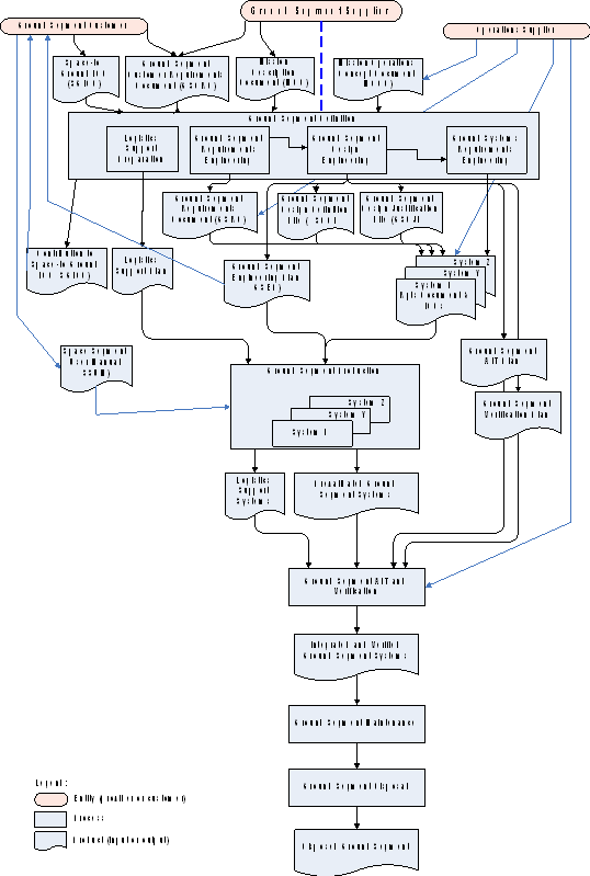 Figure 61: Schematic of ground segment engineering processes
Ground segment definition
Inputs
The inputs to the ground segment definition process shall be the ones identified in Table 61.
The contents of the ground segment customer requirements document (GSCRD) shall conform to Annex A.
- 1 The GSCRD corresponds to the “Initial technical specification” (TS) of ECSS-E-ST-10-06 tailored for the ground segment domain.
- 2 The ground segment customer consults with the end-user community to ensure that its requirements are appropriately captured in the GSCRD.
Table 61: Inputs to the ground segment definition process
|
ID
|
Title
|
Mnemonic
|
Provider
|
|
1
|
Ground segment customer requirements document
|
GSCRD
|
Ground segment customer
|
|
2
|
description document
|
MDD
|
Ground segment customer
|
|
3
|
operations concept document
|
MOCD
|
Operations supplier
|
|
4
|
Space–to–ground interface control document (draft)
|
SGICD
|
Ground segment customer
|
Process description
General
The process shall comprise the following sub-processes:
- Ground segment requirements engineering
- Ground segment design engineering
- Ground systems requirements engineering
- Logistics support preparation.
Ground segment requirements engineering
The ground segment requirements document (GSRD) shall be generated as an elaboration of the requirements of the GSCRD.
- 1 The GSRD is a tailored version of the Technical Specification (TS) of ECSS-E-ST-10-06.
- 2 This also includes user requirements produced by the operations supplier (see clause 5.2.2.5).
Requirements addressing the following topics shall be included: - functionality;
- performance of the ground segment derived from the overall space system requirements;
- dependability of the ground segment derived from the overall space system requirements
- security of the ground segment;
- mission safety;
- operations and logistics support;
- internal and external interfaces;
- re–use of generic infrastructure elements;
For example, software systems, and ground station equipment.
- maintainability of hardware and software;
- location of ground systems and site diversity aspects;
- failure case operations and recovery and fall back (equipment and communication fault tolerance, automatic or manual recovery);
- system management (user administration, access authorization, equipment configuration, performance monitoring);
- configuration management;
- network design and management (stations and communications);
- commonality between ground systems;
For further guidance see Annex K.
- interoperability aspects.
For example, use of ground station capabilities of other agencies or suppliers.
Ground segment design engineering
The results of the ground segment design engineering shall be documented in the ground segment design definition file (GSDDF).
- 1 The purpose of ground segment design engineering is to derive an architecture from the ground segment requirements and to develop the associated engineering plan.
- 2 The generic contents of the ground segment design definition file are defined in ECSSEST10.
The ground segment architecture shall be defined down to the level of individual ground systems.
The architecture shall cover integrated logistics support systems in accordance with the “Requirements for control of logistic activities” of ECSSMST70.
The verification and validation approach and associated tools and data shall be defined.
Ground segment design shall include an analysis to assess the possibility of reuse of existing systems, including multi-mission infrastructure and customisations and modifications related thereto.
The ground segment design shall define the internal and external interfaces.
The critical elements of the ground segment in terms of mission success, of the associated reliability, availability, maintainability and safety requirements and risk-mitigation measures shall be identified.
The ground segment design justification file (GSDJF) shall document the justification of the design, including design trade-offs, requirement traceability matrices, results of analyses and assessments.
The engineering plan for the ground segment (GSEP) shall be developed in accordance with the requirements on “System engineering plan” of ECSSEST10.
The GSEP describes the approaches, techniques, tools, organization, planning and scheduling of the technical effort to accomplish the ground segment objectives.
The following ground segment system level documents shall be developed:
- The ground segment AIT plan.
- The ground segment verification plan. Contributions to the space-to-ground interface control document (SGICD) shall be prepared addressing:
- RF interfaces.
- Voice, video and high-rate data transmission.
See AOS Networks and Data Links: Architectural Specification, CCSDS 701.0-B-2.
Ground systems requirements engineering
A ground system requirement document shall be produced for each ground system identified in the GSDDF, including where applicable integrated logistics support systems.
- 1 For technical specification see ECSS-E-ST-10-06.
- 2 The purpose of ground systems requirements engineering is to produce the requirements for each individual ground system identified in the GSDDF.
- 3 This also includes user requirements produced by the operations supplier (see clause 5.2.2.5).
Requirements of at least the following categories shall be covered : - Functional;
- Performance;
- Interface;
- Design;
- Operational;
- Environment;
- Resource;
- Reliability, availability, maintainability and safety;
- Security;
- Verification.
For software systems, the requirements engineering process of ECSSEST40, clause “Software requirement analysis” shall be applied.
The traceability to the GSRD shall be included in each ground system requirement document.
ICDs shall be generated for all external interfaces of each ground system.
Internal interfaces i.e. those within each system are addressed in clause 6.3 as part of the ground system production process.
Logistics support preparation
Logistics support activities shall be defined concurrently with the supported system.
As specified in ECSS-M-ST-70, logistic support activities are an integral part of any system development.
The objective of logistics support shall be to maintain the technical performance of ground systems and operations teams, whilst respecting safety constraints and optimising overall life cycle costs.
A logistics support plan shall be generated which responds to the logistics support requirements contained in the GSCRD, addressing the following issues:
- Staffing, training and proficiency maintenance.
- Spares provisioning.
- Procurement of support equipment.
- Provision of software support.
- Packaging, handling, storage (PHS) and transport. The logistics support plan shall identify the available or shared resources that can be deployed in support of the mission and those that are procured for the mission.
Outputs
The outputs of the ground segment definition process shall be the ones specified in Table 62.
Table 62: Output of the ground segment definition process
|
ID
|
Title
|
Mnemonic
|
Producer
|
|
1
|
Ground segment system requirements documents
|
GSRD
|
Ground segment supplier
|
|
2
|
Ground segment engineering plan
|
GSEP
|
Ground segment supplier
|
|
3
|
Ground segment design definition file
|
GSDDF
|
Ground segment supplier
|
|
4
|
Ground segment design justification file
|
GSDJF
|
Ground segment supplier
|
|
5
|
ICDs for external entities (part of the GSDDF)
|
ICDs
|
Ground segment supplier
|
|
6
|
Logistics support plan (draft)
|
|
Ground segment supplier
|
|
7
|
Ground systems requirements documents
|
|
Ground segment supplier
|
|
8
|
Ground segment AIT plan
|
GSAITP
|
Ground segment supplier
|
|
9
|
Ground segment verification plan
|
GSVP
|
Ground segment supplier
|
|
10
|
Contribution to the space-to-ground interface control document
|
SGICD
|
Ground segment customer
|
Ground segment production
Inputs
The inputs to the ground segment production process shall be the ones specified in Table 63.
Table 63 Inputs to the ground segment production process
|
ID
|
Title
|
Mnemonic
|
Provider
|
|
1
|
Ground segment engineering plan
|
GSEP
|
Ground segment supplier
|
|
2
|
Ground segment design definition file
|
GSDDF
|
Ground segment supplier
|
|
3
|
Ground segment design justification file
|
GSDJF
|
Ground segment supplier
|
|
4
|
Ground segment AIT plan
|
GSAITP
|
Ground segment supplier
|
|
5
|
Ground segment verification plan
|
GSVP
|
Ground segment supplier
|
|
6
|
Logistics support plan (draft)
|
|
Ground segment supplier
|
|
7
|
ICDs for external entities
|
ICDs
|
Ground segment supplier
|
|
8
|
Ground systems requirements documents
|
|
Ground segment supplier
|
|
9
|
Space segment user manual*
|
SSUM
|
Ground segment customer
|
|
10
|
Space segment monitoring and control database*
|
|
Ground segment customer
|
|
* where applicable
| |||
Process description
For each GS system, the system engineering process of ECSS-E-ST-10, consisting of definition, production, AIT and verification, and maintenance, shall be applied (also recursively to lower levels), including the related documentation model.
- 1 The production process for the Ground Segment is implemented at the next lower level of decomposition, i.e. GS systems. This covers the procurement of those systems directly involved in operating the mission and also support systems or tools for testing, for maintenance, and for training of personnel.
- 2 For some missions, the operational simulator can be provided by the space segment supplier (or even by a third party). However, in the context of the production of the operational simulator, he is considered as a ground system supplier.
- 3 In the context of the complete ground segment (i.e. all ground systems fully integrated), the ground segment supplier is responsible for all constituent ground systems vis-à-vis both the ground segment customer and the operations supplier.
- 4 Appropriate international, European or national standards or regulations should be considered. Local organisational standards may also apply, where these reference the appropriate ECSS, international, European or national standards.
The design of each ground system shall include an analysis to assess the possibility of reuse of existing systems, including related multi-mission infrastructure.
For commonality considerations see Annex K.
For software systems, ECSS-E-ST-40 and ECSS-Q-ST-80 shall apply.
The supplier of each ground system shall support delivery, installation and on-site acceptance.
Qualification/acceptance tests shall be performed against the contents of the corresponding ground system requirements document.
Qualification/acceptance tests shall be performed in the defined target environment.
- 1 Qualification can include a Factory Acceptance Test (FAT) at the system supplier’s premises.
- 2 Specific dedicated test facilities (hardware or software) can be developed or procured in parallel with the ground system itself for verifying functional performances and interface requirements.
Acceptance test reports shall be produced for each ground system.
User manuals shall be produced for each ground system.
Maintenance manuals and procedures shall be produced for each ground system.
Outputs
The outputs of the ground segment production process shall be the ones specified in Table 64.
Table 64: Outputs of the ground segment production process
|
ID
|
Description
|
Producer
|
|
1
|
Qualified ground systems
|
Ground system suppliers
|
|
2
|
Acceptance reports for each ground system
|
Ground system customer
|
|
3
|
User manuals for each ground system
|
Ground system suppliers
|
|
4
|
Maintenance manuals and procedures for each ground system
|
Ground system suppliers
|
|
5
|
Test and training tools
|
Ground system suppliers
|
Ground segment AIT and verification
Inputs
The inputs to the ground segment AIT and verification process shall be the ones specified in Table 65.
Table 65: Inputs to the ground segment AIT and verification process
|
ID
|
Description
|
Provider
|
|
1
|
Ground segment engineering plan
|
Ground segment supplier
|
|
2
|
Ground segment AIT plan
|
Ground segment supplier
|
|
3
|
Ground segment verification plan
|
Ground segment supplier
|
|
4
|
Logistics support plan
|
Ground segment supplier
|
|
5
|
Accepted ground systems ready for integration
|
Ground system suppliers
|
|
6
|
User and maintenance documentation for each ground system
|
Ground system suppliers
|
|
7
|
Test and training tools
|
Ground system suppliers
|
|
8
|
Integrated logistics support systems
|
Ground system suppliers
|
|
9
|
Space segment software code and associated documentation
|
Ground segment customer
|
|
10
|
specific launcher interface control document
|
Ground segment customer
|
|
11
|
The spacecraft for ground segment compatibility tests
|
Ground segment customer
|
|
12
|
Representative space segment TM data samples
|
Ground segment customer
|
|
13
|
Suitcase
|
Ground segment customer
|
|
14
|
Preliminary set of mission operations data
|
Operations supplier
|
Process description
General
The ground segment AIT activity shall:
- Be performed using a preliminary set of mission operations data.
- Be carried out in an incremental manner, starting from low-level subsystems up to ground segment level, including at each stage of the process:
- a verification test, to demonstrate the conformance of the system with its design specification and interfaces to other ground segment systems, and
- a validation test, to provide a preliminary confirmation that it is fit for use.
The ground segment verification activity shall:
- Follow the ground segment integration, addressing the ground segment systems as a whole.
- Result in:
- demonstrating the conformance of the ground segment to the requirements and design specifications,
- verifying the functional coherence of the ground systems and their compatibility,
- verifying the compatibility of the ground segment with the space segment,
- verifying the compatibility of the ground segment with the external ground entities, by carrying out a series of end–to–end tests which involve external interfaces of the ground systems, and
- providing a preliminary confirmation of the conformity of the ground segment systems as a whole with their intended use, by exposing them to realistic operational conditions.
For verification activities see ECSS-E-ST-10-02.
The integrated logistics support systems shall be integrated and validated in conformance with the “Requirements for control of logistic activities” of ECSSM-ST-70.
When validating the integrated logistics system it shall be ensured that the support elements are usable in the operational environment in conformance with the “Requirements for control of logistic activities” of ECSSMST-70.
Any subsequent modifications to the ground systems shall necessitate non-regression testing during which the ground segment shall undergo verification (activity 6.4.2.1b).
Figure 62 shows the overall ground segment AIT and verification process. The final activity shown in Figure 62, ground segment operational validation, is part of operations engineering (see clause 5.6) but is included here to give an overall view of the entire approach.
 Figure 62: Ground segment AIT and verification
Ground segment AIT
Ground segment AIT shall be documented in the ground segment AIT plan, by a set of test procedures and in reports covering all stages of the process.
The AIT Plan can be incorporated in the SEP or can be a standalone document.
The ground segment AIT plan shall:
- Include the steps from the receipt of the first integration release to the completion of integration.
- Cover the following aspects:
- The execution of each of the tests covered by the test specifications and production of the associated test documentation;
- the sequence in which the individual systems are integrated, taking account of expected readiness;
- the use of test systems or simulators;
- the integration with individual external elements;
- the relationship between these tests and planned pre–releases of the systems for ground segment AIT purposes.
The results of the tests performed during ground segment AIT shall be assessed at a post test review.
Ground segment verification
Ground segment verification shall cover:
- Conformance of the ground segment, including its constituent systems, to its design requirements and specifications.
- Ensuring adequacy of the maintenance manuals and maintenance procedures for operations, conformance with the SGICD and with the ICDs for external interfaces, and
- validation of the operational adequacy of the ground segment. The OS shall support the corresponding validation tests and the production of the associated reports, including ground segment verification reports and a ground segment preliminary acceptance report.
The different stages of ground segment acceptance are addressed in clause 7.5.3.
Verification of the ground segment shall include verification of its compatibility with the space segment.
This can include the use of the following test resources:
- suitcase representative of spacecraft hardware and software equipment for testing RF and telemetry, telecommand and tracking protocols and format compatibility between space segment and the ground stations;
- operational simulator including realistic software models of the space segment elements (e.g. emulators for complex software elements) and in some cases real spacecraft components (hybrid simulator);
- representative space segment telemetry data samples;
- access to the spacecraft on ground during space segment AIT activities and at the launch site, involving as far as is technically feasible, tests of all ground systems and functions.
For the space-to-ground compatibility tests, at least two periods shall be provided of a duration that is commensurate with the complexity of the space segment and with an interval between them allowing correction of potential ground segment problems found during the first period of tests.
In addition, “listen-in” tests are generally provided on an opportunity basis. These are open-loop tests where telemetry generated during the space segment AIT programme is routed to the mission control centre.
The space–to–ground segment compatibility tests shall include the mission operations data and the corresponding ground systems elements.
For example, mission operations data can include monitoring and control databases, operational procedures and command schedules.
The results of the tests performed during ground segment verification shall be assessed through a formal review process, the ground segment qualification review (GSQR).
Outputs
The outputs of the ground segment AIT and verification process shall be the ones specified in Table 66.
Table 66: Outputs of the ground segment AIT and verification process
|
ID
|
Description
|
Producer
|
|
1
|
Verified ground segment ready for operational validation
|
Ground segment supplier
|
|
2
|
Ground segment integration reports including test results (part of GSDJF)
|
Ground segment supplier
|
|
3
|
Ground segment verification reports (part of GSDJF)
|
Ground segment supplier
|
|
4
|
Ground segment preliminary acceptance report
|
Operations supplier
|
Ground segment maintenance
Inputs
The inputs to the ground segment maintenance process shall be the ones specified in Table 67
Table 67: Inputs to the ground segment maintenance process
|
ID
|
Title
|
Mnemonic
|
Provider
|
|
1
|
Ground segment requirements document
|
GSRD
|
Ground segment supplier
|
|
2
|
Ground segment engineering plan
|
GSEP
|
Ground segment supplier
|
|
3
|
Logistics support plan
|
|
Ground segment supplier
|
|
4
|
Ground segment design definition file
|
GSDDF
|
Ground segment supplier
|
|
5
|
Ground segment design justification file
|
GSDJF
|
Ground segment supplier
|
|
6
|
Ground systems design documentation (including the integrated logistics support systems)
|
|
Ground segment supplier
|
|
7
|
Maintenance manuals and procedures for each ground system
|
|
Ground system suppliers
|
Process description
Introduction
The maintenance process contains the activities and tasks of the ground segment maintainer. The objective is to ensure the correct operation of the ground segment in line with its availability and performance requirements. This process also includes obsolescence management and can include the migration activities for example as computer equipment or operating systems reach their end of service.
The activities provided in this sub-clause are specific to the maintenance process; however, the process can utilize other processes in this Standard, for example if a migration involves redevelopment or if certain processes have to be repeated for e.g. non-regression testing. If the ground segment engineering processes (clauses 6.2 to 6.4) are utilized, the term supplier there is interpreted as maintainer.
Process description
Regular performance monitoring shall be undertaken in order to identify trends or degradations indicating the need for preventive maintenance
Performance monitoring results shall be recorded in performance reports.
Routine maintenance shall be planned and undertaken in accordance with maintenance procedures accompanying the delivered system.
For example, lubrication of moving parts, replacement of limited lifetime items, and software log file purging.
Maintenance activities shall be recorded in a maintenance log.
The incident management process shall log incidents and restore normal service operation in line with availability requirements.
Problem management shall:
- Provide reactive fault diagnosis and proactive trend analysis to identify, record, report on and rectify root causes of incidents and prevent future incidents and problems.
- Liaise closely with incident management and ensure that identified problems are logged and communicated.
- Generate corresponding change requests. Change management shall cover:
- Impact assessments.
- Planning and implementation of change requests.
- Production of new releases.
- Management of introduction of new releases into operational systems.
For change management see ECSS-M-ST-40.
Configuration management shall cover:
- The maintenance of a configuration management database.
- Support of configuration documentation.
- Management of configuration items.
- 1 For configuration management see ECSS-M-ST-40.
- 2 Configuration items include hardware components, network components, software components including also COTS, documentation, configuration data, mission operations data.
Obsolescence management shall cover the monitoring of the obsolescence of the systems and the planning and implementation of replacements or upgrades.
Outputs
The outputs of the maintenance process shall be the ones specified in Table 68.
Table 68 Outputs of the maintenance process
|
ID
|
Description
|
Producer
|
|
1
|
Performance reports
|
Ground segment supplier
|
|
2
|
Maintenance logs
|
Ground segment supplier
|
|
3
|
Incident records
|
Ground segment supplier
|
|
4
|
Change requests
|
Ground segment supplier
|
|
5
|
Problem records
|
Ground segment supplier
|
|
6
|
Release plans
|
Ground segment supplier
|
|
7
|
Release deliveries
|
Ground segment supplier
|
|
8
|
Configuration management database
|
Ground segment supplier
|
Ground segment disposal
Inputs to ground segment disposal
The input to the ground segment disposal process shall be the one specified in Table 69.
Table 69: Input to the ground segment disposal process
|
Description
|
Provider
|
|
Fully operational ground segment at the declared end of the mission
|
Operations supplier
|
Process description
The disposal engineering process shall include
- Disposal analyses.
- Development of products and processes for disposal.
- Processes validation.
- Disposal or recycling of ground systems.
As defined in ECSS-E-ST-10, disposal constitutes the tasks, actions, and activities to be performed, and the system elements used, to ensure mission termination without degradation to the environment.
Disposal analysis shall cover methods for storage, dismantling, reusing, recycling and destruction of the ground segment.
The disposal analysis shall cover cost and organization of the disposal.
data shall remain accessible for a duration agreed with the ground segment customer.
The intention of this requirement is to conform to relevant regulations and to the mission requirements.
Engineering activities supporting disposal shall be documented in the disposal plans (part of the MOP).
Dismantling shall be performed in accordance with applicable environmental regulations.
Outputs
The outputs of the ground segment disposal process shall be the ones specified in Table 610.
Table 610: Outputs of the ground segment disposal process
|
ID
|
Description
|
Producer
|
|
1
|
Disposed ground segment
|
Ground segment supplier
|
|
2
|
Ground segment disposal report
|
Ground segment supplier
|
|
3
|
Data archives including post mission consolidated data and access tools
|
Ground segment supplier
|
Ground segment and operations lifecycle
General
The lifecycle
In accordance with the ECSS life cycle defined in ECSS-M-ST-10, the ground segment engineering processes are allocated to phases, which proceed in sequence and each of which ends in a formal review. As shown in Figure 71, the individual ground segment lifecycle phases are not necessarily aligned with those of the space system, however there are strong interdependencies. The operations engineering processes are also shown on Figure 71 demonstrating how operations engineering influences the ground segment engineering lifecycle.
- 1 ECSS-E-ST-10 defines the space system as constituting the space segment, the ground segment and the launch segment. The space system level is also commonly referred to as the mission-level.
- 2 In Figure 71, the phasing of the ground segment and operations lifecycles with the space system lifecycle is typical and can vary in detail from mission to mission.
For each phase, this clause identifies the processes, milestones and major review(s). No contractual acceptance reviews are shown, since these can be associated with different milestones depending on the procurement approach.
The space system level reviews shown in Figure 71 are defined in ECSS-M-ST-10. The reviews specific to the ground segment and operations are defined within this Standard.
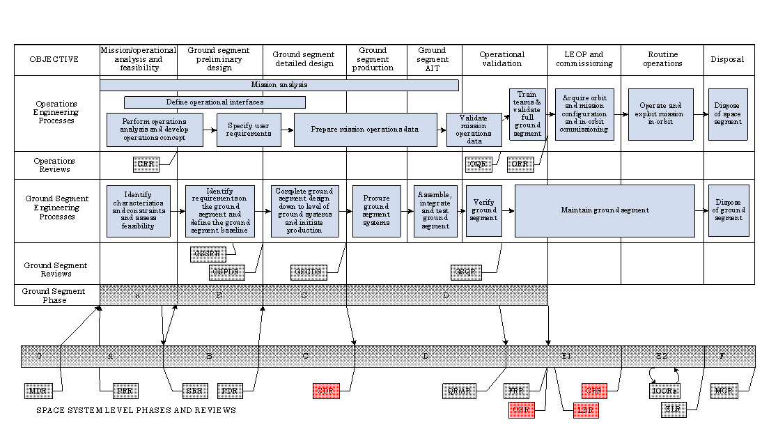 Figure 71: Ground segment and operations phases
General requirements
The GSC, the OC, the GSS and the OS shall be represented in the ground segment and operations reviews.
Ground segment reviews and operations reviews should be combined wherever practical.
In particular where the GSS and OS are part of the same entity.
For missions of an incremental nature (such as ISS or the European ATV), the ground segment and operations lifecycle and phases identified in this clause shall apply to each mission increment.
Incremental means comprised of a series or sequence of repeated missions using the same ground (or space) infrastructure.
Phase A: and operational analysis, feasibility studies and conceptual design
Purpose of phase A
During this phase, the requests initially expressed by the GSC and the OC are analysed in order to identify and characterize the ground segment, in terms of operational feasibility and needs, expected performance and reliability, availability, maintainability and safety objectives.
An evaluation of the operational constraints involved in the mission is performed in this phase.
Many of the activities performed during this phase, and continued or elaborated during later phases, are contributions to space system level activities. The activities concerned are those relating to mission analysis, operations concept definition and the definition of space-to-ground interfaces.
Processes during phase A
The main processes specified in Table 71 shall be carried out during phase A.
Table 71: Processes and outputs of phase A
|
ID
|
Ground Segment Engineering
|
Operations Engineering
|
Outputs
|
Reviews
|
|
1
|
|
analysis (clause 5.2.2.1)
|
Draft issue of mission analysis report (MAR) covering the various proposed solutions, see Annex C
|
CRR
|
|
2
|
|
Operational analysis and concept development (clause 5.2.2.2)
|
operations concept document (MOCD) (draft), see Annex D
|
CRR
|
|
3
|
Ground segment design engineering (clause 6.2.2.3)
|
|
Preliminary inputs to space–to–ground interface control document (SGICD) (draft)
|
CRR
|
|
4
|
|
Operational interfaces definition (clause 5.2.2.3)
|
Space segment operability requirements document (SSORD)
|
CRR
|
|
5
|
Ground segment design engineering (clause 6.2.2.3)
|
|
Preliminary version of GSEP, including identification of the necessary ground systems and assessment of use or sharing of planned or existing facilities
|
CRR
|
Milestones and reviews of phase A
The feasibility studies and conceptual design phase shall be concluded by the customer requirements review (CRR), with the main objectives of assessing the completeness of the customer requirements and reviewing the draft operations concept and ground segment baseline.
The CRR follows successful completion of the space system PRR.
Phase B: Preliminary design
Purpose of phase B
The purpose of this phase is to refine the ground segment baseline, to confirm its capability to meet the ground segment requirements and to prepare the necessary procurements for the production of the ground segment. In parallel, the mission operations concept is further developed.
Processes during phase B
The main processes specified Table 72 shall be carried out during phase B.
Table 72: Processes and outputs of phase B
|
ID
|
Ground Segment Engineering
|
Operations Engineering
|
Outputs
|
Reviews
|
|
1
|
Ground segment requirements engineering (clause 6.2.2.2)
|
Contribution to ground segment and ground systems requirements specification (clause 5.2.2.4)
|
Ground segment requirements document (GSRD)
|
GSSRR
|
|
2
|
Ground segment design engineering (clause 6.2.2.3)
|
|
Contributions to the space–to–ground interface control document (SGICD)
|
GSSRR
|
|
3
|
Logistics support preparation (clause 6.2.2.5)
|
|
Logistics support plan (preliminary)
|
GSSRR
|
|
4
|
|
analysis (clause 5.2.2.1)
|
analysis report (MAR)
|
GSSRR GSPDR
|
|
5
|
|
Operational analysis and concept development (clause 5.2.2.2)
|
operations concept document (MOCD)
|
GSSRR GSPDR
|
|
6
|
|
Operations engineering plan production (clause 5.2.2.4)
|
Operations engineering plan (OEP) (preliminary)
|
GSPDR
|
|
7
|
Ground segment design engineering (clause 6.2.2.3)
|
|
Ground segment design definition file (GSDDF) (preliminary)
|
GSPDR
|
|
Ground segment design justification file (GSDJF) (preliminary)
|
GSPDR
| |||
|
Ground segment engineering plan (GSEP) (preliminary)
|
GSPDR
| |||
|
Ground segment AIT plan
|
GSPDR
| |||
|
Ground segment verification plan
|
GSPDR
| |||
|
8
|
Ground systems requirements engineering (clause 6.2.2.4)
|
Contribution to ground segment and ground systems requirements specification (clause 5.2.2.4)
|
Ground systems requirements documents
|
GSPDR
|
|
|
ICDs for external entities (preliminary)
|
GSPDR
|
Milestones and reviews of phase B
A ground segment system requirements review (GSSRR) shall be held during phase B.
The purpose of the GSSRR shall be to approve the ground segment requirements such that preliminary design and the definition of requirements on the individual ground systems can proceed.
Phase B shall end with a ground segment preliminary design review (GSPDR), which follows the successful completion of the space system PDR.
The purpose of the GSPDR shall be to approve the preliminary ground segment design and to select the ground segment main supplier.
Phase C: Detailed design
Purpose of phase C
The purpose of the ground segment design phase is to complete the design of the ground segment to the level of individual systems and to start production.
Phase C includes the definition of the operations organization and the start of production of mission operations data (operational procedures, monitoring and control databases and detailed mission analysis).
Processes during phase C
The main processes specified in Table 73 shall be carried out during phase C.
Table 73: Processes and outputs of phase C
|
ID
|
Ground Segment Engineering
|
Operations Engineering
|
Outputs
|
Reviews
|
|
1
|
Ground segment requirements engineering (clause 6.2.2.2)
|
|
Inputs to space–to–ground interface control document (SGICD) in final version
|
GSCDR
|
|
2
|
Ground segment design engineering (clause 6.2.2.3)
|
|
Ground segment design definition file (GSDDF)Ground segment design justification file (GSDJF)
|
GSCDR
|
|
3
|
Ground segment production (clause 6.3)
|
|
Ground systems design documents
|
GSCDR
|
|
4
|
|
Operations engineering plan production (clause 5.2.2.4)
|
Operations engineering plan (OEP)
|
GSCDR
|
|
5
|
|
Operational interfaces definition (clause 5.2.2.3)
|
Space segment operability requirements document (SSORD) in final version
|
GSCDR
|
|
Customer furnished items and services requirements documents (CFISRD) in final version
|
GSCDR
| |||
|
6
|
|
analysis (clause 5.2.2.1)
|
analysis report (MAR), including preliminary sequence of events
|
GSCDR
|
|
7
|
|
operations data production (clause 5.3)
|
operations plan (preliminary)
|
|
|
Space and ground segment monitoring and control databases (preliminary)
|
Milestones and reviews of phase C
Phase C shall be concluded by the ground segment critical design review (GSCDR).
The purpose of the GSCDR shall be to establish acceptance by the customer of the detailed ground segment design.
Phase D: Production, AIT and verification
Purpose of phase D
The purpose of the phase is to procure all ground systems and to integrate them into an operational ground segment ready to support the in–orbit operations and exploitation of the space segment.
Processes during phase D
The main processes specified in Table 74 shall be carried out during phase D:
Table 74: Processes and outputs of phase D
|
ID
|
Ground Segment Engineering
|
Operations Engineering
|
Outputs
|
Reviews
|
|
1
|
|
analysis (clause 5.2.2.1)
|
analysis report (MAR) in final version
|
GSQR
|
|
2
|
Ground segment production (clause 6.3)
|
|
Qualified ground systems
|
|
|
Test and training tools
|
|
|||
|
Qualification test report for each ground system
|
GSQR
| |||
|
User and maintenance documentation for each ground system
|
|
|||
|
3
|
Ground segment AIT and verification (clause 6.4)
|
|
Qualified ground segment and mission operations data
|
GSQR
|
|
Ground segment maintenance and logistics plan
|
GSQR
| |||
|
Ground segment AIT reports
|
GSQR
| |||
|
Ground segment qualification report
|
GSQR
| |||
|
4
|
|
operations data production (clause 5.3)
|
operations plan
|
|
|
5
|
|
Operational validation plan production (clause 5.2.2.6)
|
Operational validation plan (OVP) in final version
|
COR
|
|
6
|
|
operations data validation (clause 5.4)
|
Validated mission operations plan (MOP)
|
COR
|
|
Validated space segment monitoring and control database
|
COR
| |||
|
Validated ground segment monitoring and control database
|
COR
| |||
|
operations data validation test reports
|
COR
| |||
|
7
|
|
Operations teams build–up and training (clause 5.5)
|
Operations training plan (OTP) in final version
|
COR
|
|
Training material
|
|
|||
|
Trained operations teams
|
|
|||
|
8
|
|
Operational validation (clause 5.6)
|
Operational validation reports
|
ORR
|
|
Fully validated ground segment, including personnel and procedures, ready for in–orbit operations and exploitation
|
|
Milestones and reviews of phase D
Phase D shall be subdivided into four main sub-phases (see Figure 71) as follows:
- Ground segment production.
This activity concentrates on the production and procurement of the ground systems.
- Ground segment AIT and verification.
- operations data validation.
- Operational validation For practical reasons, the sub-phases of clause 7.5.3a may overlap.
For schematic simplicity, they are shown as sequential in Figure 71.
Ground segment AIT and verification shall terminate with a ground segment qualification review (GSQR).
- 1 For ground segment AIT and verification see clause 6.4.
- 2 The GSQR ensures that the ground segment conforms to its technical requirements and that all conditions are met for proceeding with the operational validation activities
- 3 GSQR can constitute the preliminary acceptance for the ground segment.
operations data validation shall end with a critical operations review (COR).
The COR shall: - ensure that mission operations data has been validated, and
- ensure that documentation is available to start the training and operational validation.
When possible, the GSQR and COR can be combined into a single review.
Operational validation, as specified in clause 5.6, shall constitute the operational qualification of the whole ground segment.
The operational validation shall end with the operational readiness review (ORR).
For project phasing and planning see ECSSMST10.
The ORR shall:
- Ensure that the programme of simulations and rehearsals has been satisfactorily completed.
- Ensure that the ground segment is ready for operations.
- Ensure that all procedures have been validated.
- Ensure that operations teams are ready for operations.
- Authorize use of the ground segment for space segment in–orbit operations.
The ORR normally also constitutes the final acceptance of the ground segment.
The results of the ORR shall be presented at the flight readiness review (FRR).
For project phasing and planning see ECSS-M-ST-10.
Phase E: operations
Purpose of phase E
The purpose of phase E is to operate the space system in accordance with the MOP, maintain the ground segment in accordance with the logistics support plan and ground systems maintenance documentation and to handle any space system anomalies that occur.
If changes in the space segment or ground segment during phase E result in the need to modify mission operations data or ground systems, these changes are developed, verified and validated as during the earlier phases (i.e. using the same processes).
The phase is divided into two sub-phases in accordance with ECSS-M-ST-10:
Sub-phase E1 which is an overall test and commissioning phase of the space and ground segments.
Sub-phase E2 which is the utition phase itself.
Processes during phase E
The main processes specified in Table 75 shall be carried out during sub-phase E1.
The main processes specified in
Table 76 shall be carried out during sub-phase E2.
Table 75: Processes and outputs of sub-phase E1
|
ID
|
Ground Segment Engineering
|
Operations Engineering
|
Outputs
|
Reviews
|
|
1
|
|
LEOP operations (clause 5.8.2.2)
|
Space segment elements in their final orbits and configured for commissioning operations;
|
FQR
|
|
2
|
|
Commissioning operations (clause 5.8.2.2)
|
Commissioned space segment;
|
FQR
|
|
3
|
|
Ground segment operations (clause 5.8.2.3)
|
Ground segment elements configured for operations
|
FQR
|
Table 76: Processes and outputs of sub-phase E2
|
ID
|
Ground Segment Engineering
|
Operations Engineering
|
Outputs
|
Reviews
|
|
1
|
|
Space segment routine in–orbit operations (clause 5.8.2.3)
|
Routine operations reports;
|
IOORs
|
|
|
Planning and scheduling of space segment and of supporting ground segment entities
|
Space segment plans and schedules;
|
|
|
|
|
Space segment performance and trend analysis
|
Performance and trend analysis data and associated reports;
|
|
|
|
|
Payload utilization operations, data acquisition and distribution
|
products - payload products;
|
|
|
|
|
Handling of space and ground segments anomalies
|
Operations anomaly report (OAR), see Annex I
|
|
|
|
2
|
|
Operational configuration management (0)
|
Trained ground teams
|
IOORs
|
|
3
|
|
Ground segment operations (clause 5.8.2.3)
|
Ground segment elements configured for operations
|
IOORs
|
|
4
|
Ground segment maintenance (clause 6.5)
|
|
Fully operational ground systems
|
IOORs
|
|
5
|
|
operations data production (clause 5.3)
|
operations plan (sections pertaining to disposal of space and ground segments)
|
ELR
|
Milestones and reviews of phase E
Phase E1 shall be concluded by the flight qualification review (FQR). This review shall be held after completion of the space segment in–orbit commissioning, in order to assess performance of the space and ground segments and declare readiness for in–orbit exploitation.
During the utition phase (E2) in–orbit operations reviews (IOORs) shall be held on a regular basis to assess the performance of the space system, i.e. both space segment and ground segment .
For example, on a yearly basis.
Phase E2 shall be concluded by the end-of-life review (ELR), which shall verify that the mission has completed its useful operation or service and that the procedures for disposal are in place.
Phase F: Disposal
Purpose of phase F
During phase F the space segment is withdrawn from service, after preparation and planning in liaison with the space segment customer. This can include transferring the spacecraft to another orbit, with eventual landing or destructive re–entry.
Processes during phase F
The main processes specified in Table 77 shall be carried out during phase F:
Table 77: Processes and outputs of phase F
|
ID
|
Ground Segment Engineering
|
Operations Engineering
|
Outputs
|
Reviews
|
|
1
|
|
Preparation and execution of mission termination and space segment disposal operations (clause 5.9)
|
Disposed space segment
|
MCR
|
|
2
|
Preparation and execution of ground segment disposal (clause 6.6)
|
|
Disposed ground segment
|
MCR
|
|
3
|
|
Documentation of mission operations experience (clause 5.8.2.4)
|
reports including, for example, mission operations experience, summary of spacecraft in–orbit performance, results of end-of-life tests
|
|
Milestones and reviews of phase F
Phase F shall be concluded by the mission close–out review (MCR).
The purpose of the MCR shall be to assess the performance of the services provided and to confirm proper disposal of space and ground segments.
Summary of key documents and reviews
Table 78 provides a list of the key ground segment and operations documents and the ground segment and operations reviews at which different releases of the documents are deliverable.
Table 79 provides a summary of the major ground segment and operations reviews.
Table 78: Key ground segment and operations documents and reviews at which they are deliverable
|
Domain |
Type |
Title |
Mnemonic |
Reference |
CRR |
GSSRR |
GSPDR |
GSCDR |
GSQR |
COR |
ORR |
FRR |
FQR |
IOOR |
ELR |
MCR |
||
|
SSYS |
MISC |
description document |
MDD |
ECSS-E-ST-10 |
A |
|
|
|
|
|
|
|
|
|
|
|
||
|
SSYS |
REQ |
Operations customer requirements document |
OCRD |
Annex B |
F |
A |
|
|
|
|
|
|
|
|
|
|
||
|
SSYS |
REQ |
Ground segment customer requirements document |
GSCRD |
Annex B |
F |
A |
|
|
|
|
|
|
|
|
|
|
||
|
SSYS |
I/F |
Space segment user manual |
SSUM |
Annex F |
|
|
|
|
|
A |
|
|
|
|
|
|
||
|
SSYS |
REP |
Trade-off report |
|
ECSS-E-ST-10 |
A |
|
|
|
|
|
|
|
|
|
|
|
||
|
SSYS |
I/F |
Launcher user manual |
|
|
F |
|
|
|
|
|
|
|
|
|
|
|
||
|
SSYS |
I/F |
Space–to–ground interface control document |
SGICD |
ECSS-E-ST-10 |
P |
F |
|
A |
|
|
|
|
|
|
|
|
||
|
SSYS |
REQ |
Space segment operability requirements document |
SSORD |
ECSS-E-ST-70-11 |
F |
|
|
A |
|
|
|
|
|
|
|
|
||
|
SSYS |
REQ |
Customer furnished items and services requirements document |
CFISRD |
Annex K |
F |
|
|
A |
|
|
|
|
|
|
|
|
||
|
GSEG |
REQ |
Ground segment requirements document |
GSRD |
ECSS-E-ST-10 -06 |
|
F |
|
|
|
|
|
|
|
|
|
|
||
|
GSEG |
SPEC |
Ground segment engineering plan |
GSEP |
ECSS-E-ST-10 |
P |
|
P |
F |
|
|
|
|
|
|
|
|
||
|
GSEG |
I/F |
ICDs for internal and external entities |
|
ECSS-E-ST-10 |
|
|
P |
F |
|
|
|
|
|
|
|
|
||
|
GSEG |
SPEC |
Ground segment design definition file |
GSDDF |
ECSS-E-ST-10 |
|
|
P |
F |
|
|
|
|
|
|
|
|
||
|
GSEG |
SPEC |
Ground segment design justification file |
GSDJF |
ECSS-E-ST-10 |
|
|
P |
F |
|
|
|
|
|
|
|
|
||
|
GSEG |
PLAN |
Ground segment configuration management plan |
|
ECSS-M-ST-40 |
|
|
P |
F |
|
|
|
|
|
|
|
|
||
|
GSEG |
PLAN |
Ground segment AIT plan |
GSAITP |
ECSS-E-ST-10-02 |
|
|
P |
F |
|
|
|
|
|
|
|
|
||
|
GSEG |
PLAN |
Ground segment verification plan |
GSVP |
ECSS-E-ST-10-02 |
|
|
P |
F |
|
|
|
|
|
|
|
|
||
|
GSEG |
REP |
Ground segment configuration status report |
|
|
|
|
|
|
F |
|
|
|
|
|
|
|
||
|
GSEG |
REP |
Ground segment integration and test reports |
|
ECSS-E-ST-10-02 |
|
|
|
|
F |
|
|
|
|
|
|
|
||
|
GSEG |
REP |
Ground segment verification reports |
|
ECSS-E-ST-10-02 |
|
|
|
|
F |
|
|
|
|
|
|
|
||
|
GSYS |
REQ |
Ground systems requirements documents |
|
ECSS-E-ST-10-06 |
|
|
F |
|
|
|
|
|
|
|
|
|
||
|
GSYS |
I/F |
Ground systems user and maintenance manuals |
|
|
|
|
|
|
F |
|
|
|
|
|
|
|
||
|
LS |
PLAN |
Logistics support plan |
LSP |
|
P |
|
|
|
F |
|
|
|
|
|
|
|
||
|
OPS |
REP |
analysis report |
MAR |
Annex C |
P |
F |
F |
F |
F |
|
|
|
|
|
|
|
||
|
OPS |
MISC |
operations concept document |
MOCD |
Annex D |
P |
F |
F |
|
|
|
|
|
|
|
|
|
||
|
OPS |
SPEC |
Operations engineering plan |
OEP |
Annex E |
|
|
P |
F |
|
|
|
|
|
|
|
|
||
|
OPS |
PLAN |
Operational validation plan |
OVP |
Annex G |
|
|
|
|
|
F |
|
|
|
|
|
|
||
|
OPS |
PLAN |
Operations training plan |
OTP |
|
|
|
|
|
|
F |
|
|
|
|
|
|
||
|
OPS |
PLAN |
operation plan |
MOP |
Annex H |
|
|
|
|
|
F |
A |
A |
|
|
A |
|
||
|
OPS |
REP |
Operational validation reports |
|
|
|
|
|
|
|
F |
F |
F |
|
|
|
|
||
|
OPS |
REP |
LEOP reports |
|
|
|
|
|
|
|
|
|
|
F |
|
|
|
||
|
OPS |
REP |
Commissioning report |
|
|
|
|
|
|
|
|
|
|
F |
|
|
|
||
|
OPS |
REP |
Performance reports |
|
|
|
|
|
|
|
|
|
|
|
F |
|
|
||
|
OPS |
REP |
Routine operations reports |
|
|
|
|
|
|
|
|
|
|
|
F |
|
|
||
|
OPS |
REP |
Operations anomaly report |
OARs |
Annex I |
|
|
|
|
|
|
|
|
|
F |
|
|
||
|
OPS |
REP |
reports |
|
|
|
|
|
|
|
|
|
|
|
|
|
|
||
|
OPS |
REP |
Disposal operations reports |
|
|
|
|
|
|
|
|
|
|
|
|
|
F |
||
|
Legend: Domain: SSYS: Space system level document GSEG: Ground segment level document GSYS: Ground system level document LS: Logistics support document OPS: Operations document |
Type: I/F: Interfaces level documents (internal or external) MISC: Miscellaneous PLAN: Plan REP: Report REQ: Requirements document SPEC: Design specification |
Release: A: Issue of the document approved by the customer F: Final issue of the document approved by supplier and provided for information to the customer P: Preliminary issue of the document |
||||||||||||||||
Table 79: Ground segment and operations reviews
|
Review ID
|
Review title
|
Review objective
|
Date
|
Chaired by
|
|
CRR
|
Customer requirements review
|
To assess the completeness of the customer requirements and review the draft operations concept and ground segment baseline
|
End of phase A
|
Operations customer and ground segment customer
|
|
GSSRR
|
Ground segment system requirements review
|
To approve the ground segment requirements such that preliminary design and the definition of requirements on the individual ground systems can proceed
|
During phase B, at the completion of the ground segment requirements engineering activity
|
Ground segment customer
|
|
GSPDR
|
Ground segment preliminary design review
|
To approve the preliminary ground segment design and to select the ground segment main supplier
|
End of phase B
|
Ground segment customer
|
|
GSCDR
|
Ground segment critical design review
|
To establish acceptance by the customer of the detailed ground segment design
|
End of phase C
|
Ground segment customer
|
|
GSQR
|
Ground segment qualification review
|
To ensure that the ground segment conforms to its technical requirements and that all conditions are met for proceeding with the operational validation activities
|
During phase D, at the end of ground segment AIT and verification
|
Ground segment supplier
|
|
COR
|
Critical operations review
|
To ensure that all mission operations data has been validated and that all documentation is available to start the training and operational validation phase
|
During phase D, at the end of mission operations data validation
|
Operations customer
|
|
ORR
|
Operational readiness review
|
To ensure full readiness of the ground segment for in orbit operations, and to authorize its utilization for space segment in-orbit operations. To ensure that all procedures have been validated and that operations teams are ready for operations.
|
End of phase D, after completion of operational validation
|
Operations customer
|
|
FQR
|
Flight qualification review
|
To assess the performance of the space and ground segments after in–orbit commissioning and to declare readiness for in–orbit exploitation
|
End of phase E1, after the completion of the commissioning activities
|
Operations customer and ground segment customer
|
|
IOORs
|
In–orbit operations reviews
|
To carry out a regular assessment of the performance of the space system, i.e. both space segment and ground segment
|
During phase E2 on a regular basis (e.g. yearly)
|
Operations customer and ground segment customer
|
|
ELR
|
End-of-life review
|
To verify that the mission has completed its useful operation or service and that the procedures for disposal are in place
|
End of phase E2
|
Operations customer and ground segment customer
|
|
MCR
|
close–out review
|
To assess the performance of the services provided and to confirm proper disposal of space and ground segments
|
End of phase F
|
Operations customer and ground segment customer
|
ANNEX(normative)Customer requirements document (CRD) - DRD
DRD identification
Requirement identification and source document
This DRD is called from ECSS-E-ST-70 requirements 5.2.1b. and 6.2.1b.
Purpose and objective
The objective of the customer requirements document (CRD) is to provide all essential top-level assumptions, constraints and operational requirements for the mission to allow the supplier(s) of the ground segment and/or operations to design the ground segment and/or to develop an operations concept.
Expected response
Scope and content
Introduction
The introduction shall describe the purpose and objective of the CRD.
Applicable and reference documents
The CRD shall list the applicable and reference documents in support of the generation of the document.
overview
The CRD shall describe:
- the main objectives and characteristics of the space mission;
- the spacecraft;
- the instruments on-board;
- the ground segment that is foreseen for the control and operations of the spacecraft, the instruments and the ground segment itself;
- the operations that are foreseen to achieve the goal of the space project. Project responsibilities
The CRD shall describe the distribution of responsibilities within the space project, including the responsibilities of the space project customer and those of the ground segment supplier and/or operations supplier.
Major project milestones
The CRD shall summarize the major project milestones relating to the space segment and the ground segment.
constraints
The CRD shall describe any constraints or other essential mission information that impacts on the design of the ground systems or the mission operations, including:
- the launch vehicle, the launch site location, the ascent trajectory and the injection characteristics;
- the main orbital parameters for each distinct orbital phase i.e. wherever the orbit changes significantly;
- identification of each distinct operational phase and any constraints on the use of the ground segment for the phase;
- any constraints imposed on the ground segment by the satellite, for example, uplink and downlink RF frequencies, on-board antenna patterns. operations requirements
The CRD shall list the high level requirements on mission operations and, by derivation, on the ground segment, at a level sufficient to define the mission operations concept.
This drives the major decisions concerning the design and deployment of the ground segment.
The requirements shall be organized according to the following operations functional breakdown:
- mission planning and scheduling;
- monitoring and control;
- performance monitoring and evaluation;
- flight dynamics;
- payload operations and data management:
- payload operations planning;
- payload operations control;
- payload data processing;
- payload data archiving;
- user services;
- data product delivery;
- performance analysis.
- on-board software maintenance;
- other mission-specific operations functions. For the GSCRD, requirements of the following classes shall be included for each major functional heading:
- functional;
- performance;
- availability;
- operational;
- interface;
- design (implementation);
- reliability;
- maintainability;
- safety;
- security;
- human-computer interaction (HCI).
Usually the requirements for a given function differ according to mission phase.
Special remarks
Where the ground segment supplier and operations supplier belong to the same organization, the ground segment customer requirements document (GSCRD) and the operations customer requirements document (OCRD) may be combined into a single document.
For large distributed ground segments, the GSCRD may be separated into self-contained documents addressing specific entities.
For example:
- A flight operations segment and a payload data segment (e.g. Envisat or ERS).
- A mission control centre and a science operations centre (e.g. observatory missions like XMM or Integral).
- Ground control segment and mission data segment (e.g. Galileo).
ANNEX(normative) analysis report (MAR) - DRD
DRD identification
Requirement identification and source document
This DRD is called from ECSS-E-ST-70 requirement 5.2.2.1c.
Purpose and objective
The objective of the mission analysis report (MAR) is to provide all the information on the mission characteristics, in particular its orbit and attitude, in sufficient detail for the planning and execution of mission operations. The MAR also provides input to the spacecraft and mission design.
Expected response
Scope and content
Introduction
The introduction shall describe the purpose and objective of the MAR.
Applicable and reference documents
The MAR shall list the applicable and reference documents in support of the generation of the document.
requirements and constraints
The MAR shall identify all pertinent requirements and constraints arising from the following:
- the mission definition, including the scientific objectives;
- the spacecraft platform and payload design;
- data recovery and data circulation;
- the selected launcher;
- orbit and ground station network. overview
The MAR shall provide a description of the baseline mission, summarises the basic characteristics of the spacecraft and the launch vehicle and identifies the different mission phases, their characteristics and duration.
Launch and early orbit phase
For the selected launch vehicle, the MAR shall describe:
- launch window characteristics (general, seasonal, daily);
- launch target orbit
- launch sequence of events;
- eclipses during the launch phase;
- ground station coverage;
- launcher injection errors. For the early orbit phase, the MAR shall describe:
- ground station coverage;
- orbit determination concept and navigation analysis (station selection, data types, tracking schedule);
- strategy for operational orbit acquisition
For example, drift orbit (LEO missions), ABM firing (GEO missions), and escape/injection (interplanetary missions).
Transfer phase (interplanetary missions)
The MAR shall provide the following information:
- ground station coverage;
- eclipse phases and daily durations;
- Earth occultation phases;
- attitude control strategy;
For example, to maintain antenna Earth-pointing, to respect thermal control constraints.
- payload operational constraints;
Sensor blinding by Earth or Sun.
- transfer manoeuvre strategy. Injection into planetary orbit (interplanetary missions)
The MAR shall provide the strategy for planetary insertion or planetary flyby.
Routine phase (operation in final orbit)
For Earth-orbiting missions, the MAR shall describe:
- characteristics of the operational orbit including its evolution as a function of time;
- orbit determination concept and navigation analysis (station selection, data types, tracking schedule);
- collision avoidance strategies
For example, for constellation missions.
- seasonal eclipse phases and daily durations;
- ground station coverage;
- payload operations strategy;
- payload operational constraints
For example, sensor blinding by Earth or Sun.
- data circulation strategies. In the case of interplanetary missions, the MAR shall describe also:
- Earth occultation phases;
- orbit phasing, orbit change requirements to achieve planetary surface coverage or planetary moon encounter/flyby. Propellant budgets
The MAR shall document the propellant budget for orbit control including routine orbit change manoeuvres (and delta-V manoeuvres in the case of interplanetary missions).
Special remarks
None.
ANNEX(normative) operations concept document(MOCD) - DRD
DRD identification
Requirement identification and source document
This DRD is called from ECSS-E-ST-70 requirement 5.2.2.2b.
Purpose and objective
The objective of the mission operations concept document (MOCD) is to define the operations concepts for the various phases of the mission, covering both the space segment and the ground segment.
Expected response
Scope and content
Introduction
The introduction shall describe the purpose and objective of the MOCD.
Applicable and reference documents
The MOCD shall list the applicable and reference documents in support of the generation of the document.
operations requirements and constraints
General
The MOCD shall provide all the essential input information that drives or constrains the operations concepts.
description
The MOCD shall describe the scope of the mission, its objectives and the top-level requirements on its operations.
This information is derived from the mission analysis report and the customer requirements document.
End-users
The MOCD shall identify all distinct categories of mission end-user and describe the data products, services, associated availability and delivery requirements.
Programmatic and operational constraints
The MOCD shall identify any constraints relating to the design of the ground segment or its operation, including:
- the re-use of existing ground segment elements or infrastructure;
- the use of remote facilities for operation or maintenance of part of the space or ground segments, such as experimenter-provided control facilities or industry-provided facilities for software maintenance;
- the use of customer furnished items developed as part of the space segment programme and to be re-used for operations. Relationships with other missions/programmes
The MOCD shall describe the relationship of the mission with other missions or programmes, including:
- membership of a family of missions of the same or similar design or based on the same spacecraft platform;
- membership of a multi-national or coordinated multi-mission programme;
- agreements for the ground segment to support other concurrent missions or programmes or to process data from other missions. External dependencies or interfaces with other organizations
The MOCD shall describe the operational interfaces with other agencies, companies or other third parties.
Space segment characteristics
The MOCD shall describe the capabilities and characteristics of the space segment platform, payload(s) and the space link subnet, including:
- on-board autonomous functions;
- the mechanisms for on-board generation, storage and downlink of mission data products;
- the end-user services to be provided.
The objective is to capture all the salient operational characteristics that are needed for the analysis of the operations processes.
operations concepts
General
The MOCD shall describe the mission operations concepts for each distinct mission phase, according to the top-level breakdown of operations processes as defined in C.2.1<5.2> to <5.6>.
It is recognized that not all these processes are applicable for each mission phase and the corresponding process can therefore be omitted. For example, mission exploitation processes are not normally undertaken during the LEOP. Also:
- there can be additional mission-specific operations processes;
- the concept for realizing a given process can be the same for several mission phases, in which case it is not repeated, but it is defined once and referenced as needed.
The MOCD shall identify how to realize the operations processes with the ground systems and operations personnel.
The MOCD shall also identify: - Reuse of existing operational capabilities and services.
For example, there can be a mission requirement to re-use specific existing infrastructure, possibly modified or extended for the mission;
- Areas where existing operational capabilities cannot satisfy the concept, i.e. new developments are needed;
- Areas where trade-offs are needed.
For example, if it is not obvious whether to realize a given operational process by ground-based automation or manually by an operator.
Planning processes
The MOCD shall describe the concept for the planning and scheduling of space and ground segment operations, including:
- user request management;
- space segment routine operations;
- ground segment maintenance requests;
- constraints management;
- resources management (space and ground);
- conflict resolution;
- space segment operations scheduling;
- ground segment operations scheduling. Operations execution processes
The MOCD shall describe the concept for the implementation of scheduled operations for the space and ground segment, including:
- schedule execution;
- procedure execution;
- manual commanding;
- command pre-transmission validation and uplink management;
- command verification;
- schedule and command history archiving;
- space and ground segment health monitoring;
- failure detection, isolation and recovery (FDIR). Evaluation processes
The MOCD shall describe the concept for evaluating the success of executed operations and for monitoring the performance of the space segment, including:
- data analysis processes (trend analysis, forecasts);
- monitoring of resource availability and utilization with provision of feedback to the planning processes described earlier;
- report production (automated report production, routine operations reporting, anomaly reporting). exploitation processes
The MOCD shall describe the concept for the generation, archiving and delivery of mission products to the end-users in a timely manner, including:
- data transmission between ground entities;
- data processing on ground;
For example, generation of mission products.
- data delivery to the end-user;
- data archiving, cataloguing and retrieval;
- feedback to mission planning;
For example, to report achieved versus planned data acquisition.
Support processes
The MOCD shall describe the concepts for all other activities performed in support of operations that are not covered by any of the above categories, including:
- orbit and attitude determination and maintenance;
- orbital and geometric events prediction;
- ground station coverage predictions;
- monitoring and control database maintenance;
- ground software maintenance;
- on-board software maintenance.
Special remarks
None.
ANNEX(normative)Operations engineering plan (OEP) - DRD
DRD identification
Requirement identification and source document
This DRD is called from ECSS-E-ST-70 requirement 5.2.2.4a.4.
Purpose and objective
The objective of the operations engineering plan (OEP) is to define the approach, methods, procedures, resources and organization to co-ordinate and manage all technical activities necessary to prepare for, validate and execute mission operations in conformance with the customer’s requirements.
The OEP is part of the project management plan (as defined in ECSS M-ST-10).
Expected response
Scope and content
Introduction
The introduction shall describe the purpose and objective of the OEP.
Applicable and reference documents
The OEP shall list the applicable and reference documents in support of the generation of the document.
overview
The OEP shall describe:
- the main objectives and characteristics of the space mission;
- the intended operational concept that fulfils the mission objectives;
- an overview of the ground segment to be deployed for the mission, including internal and external entities. Operations engineering lifecycle and reviews
The OEP shall identify the following:
- the major milestones driving the operations engineering processes;
- the operations engineering lifecycle phases;
- the principal operations reviews and their objectives;
- the operations engineering critical path. Operations engineering processes
For each operations engineering process, the OEP shall define:
- The inputs, either from previous phases/processes or from ground segment engineering processes or external inputs;
For example, data provided by the operations customer.
- The engineering approach for each activity, including:
- the manpower requirements in terms of staff numbers and specific skills levels and experience;
- the tools to be utilized, identifying existing items, tailoring required of existing infrastructure items, special-to-project facilities;
- other resources required for the execution of the activity, such as support services (documentation, project control, software support, maintenance), travel budget;
- The interrelations with other engineering disciplines (space system level, space segment, ground segment engineering, quality assurance, logistics)
- The outputs of the process. As a minimum, the following operations engineering processes shall be covered:
- analysis and system studies;
- Operations analysis and concept development;
- Flight Dynamics (i.e. orbit and attitude determination and control);
- operations data production;
- operations data validation;
- Operational validation;
- Operations teams training;
- Operations execution, covering all mission phases from launch through disposal. operations teams
The OEP shall describe:
- the organizational structures of the mission operations teams for both the operations preparation and operations execution phases;
- the allocation of responsibilities to individuals (roles);
- the reporting channels and mechanisms for operational support;
For example, call-out procedures for first and second-line operations support staff.
- the recruitment profile for each mission operations team, showing how staff are phased-in (and out) and identifying any potential time-sharing or role-sharing with other concurrent missions.
Special remarks
Where the ground segment supplier and operations supplier belong to the same organization, the ground segment engineering plan (GSEP) and the OEP may be combined into a single document.
ANNEX(normative)Space segment user manual (SSUM) - DRD
DRD identification
Requirement identification and source document
This DRD is called from ECSS-E-ST-70 requirement 5.3.1b.
Purpose and objective
The objective of the space segment user manual (SSUM) is to provide the space segment design and operational information and data that is used by the ground segment supplier and operations supplier to prepare and implement mission operations.
The SSUM DRD as given in this Annex covers that part of the SSUM that is relevant to Mission Operations.
Expected response
Scope and content
Introduction
The introduction shall describe the purpose and objective of the SSUM.
Applicable and reference documents
The SSUM shall list the applicable and reference documents in support of the generation of the document.
definition
description
The SSUM shall provide a general description of the mission and identification of the content of phases from launch to disposal.
analysis constraints
The SSUM shall describe all space segment constraints to be included in mission analysis.
phases and purposes
The SSUM shall provide the results of analyses for positioning and for in-orbit operations, taking into account satellite constraints.
- Results of analyses for positioning (or initial orbits):
- pre-launch configuration;
- launch window (variations over one year);
- satellite or launch vehicle separation sequence;
- positioning strategy;
- accuracy for attitude and orbit determination;
- chronological order of nominal operational sequences;
- visibility of the ground stations used;
- detailed analysis of high-risk sequences;
- fuel consumption.
- Results of analyses for in-orbit operations:
- in-orbit flight control strategy;
For example, change of position, phasing.
* fuel consumption;
* consequences that the environment can have on operational sequences.
For example, sensor blinding, and eclipses.
- Results of analyses for space segment disposal operations. Satellite description
Design summary
The design summary shall include the following:
- summary of the satellite design, showing the definition of the platform subsystems, the distribution of functions and the major interfaces between them;
- a block diagram of the space segment;
- a top-level description of the on-board software architecture, for the platform subsystems and payload elements;
- description of the objectives of the payload as a whole and (where applicable) of each individual experiment or instrument;
- description of nominal payload operations scenarios and any constraints on payload operations.
For example, mutually exclusive modes of operation, power or resource sharing.
System-level autonomy
The system-level autonomy shall include the following:
- description of system-level autonomy provisions in the areas of mission management and fault management;
- definition, for each autonomous function, of the logic or rules used and the interfaces with the on-board subsystems or payload and the ground.
For example, inputs, and reporting mechanism.
System-level configurations
The system-level configurations shall include the following:
- drawings of the overall satellite configuration in all mission phases;
Launch, separation, following deployments;
- definition of the satellite reference axes system(s);
- drawings of the platform and equipment layouts.
System-level budgets
The system-level budgets shall provide the distribution (or allocation) of the following budgets, per platform subsystem or payload, or per mission phase:
- satellite mass evolution;
- satellite mass properties evolution;
- power consumption for all operational modes;
- power available in different mission phases;
- thermal budget and constraints and predictions;
- RF links (down and up);
- telemetry and telecommand date rates;
- memory;
- timing (including allocation between space and ground segments);
- propulsion system data;
- attitude measurement sensor data;
- pointing accuracy in routine phase;
- pointing accuracy in manoeuvre phase;
- alignment;
- outages resulting from satellite operations.
For example, pointing accuracy degradation during a manoeuvre or degraded performance during an eclipse.
Satellite-to-ground interface specifications
Provide a cross-reference to the applicable version of the SGICD.
System-level operations
<4.6.1> timelinesThe SSUM shall include:
- Baseline event timelines for each mission phase from separation from the launcher until the start of routine operations (i.e. LEOP, commissioning, payload calibration).
- Baseline event timeline for daily activities during the routine phase and any other repeat cycle of routine operations.
- Baseline event timelines for any subsequent critical (or non-routine) phases during the mission.
For example, eclipse, phases, manoeuvres, planetary, and encounters.
- Baseline event timeline for space segment disposal operations.
Each timeline shall contain a detailed description (i.e. down to the level of each single operational action) of the complete sequence of operations to be carried out, including a description of the rationale behind the chosen sequence of events, a definition of any constraints and the interrelationships between operations in the sequence.
<4.6.2> System-level modesThe SSUM shall describe all nominal and back-up modes (at the system level), including: - their purpose (i.e. circumstances under which they are used),
- operational constraints,
- resource utilization,
- the expected satellite behaviour within each mode,
- the definition of the associated modes for each platform subsystem and payload, and
- ground monitoring requirements.
The SSUM shall describe the allowable mode transitions and the operations procedure corresponding to each such transition.
Cross-reference shall be made to subsystem or payload modes and procedures defined elsewhere in the SSUM.
<4.6.3> System-level failure analysisThe SSUM shall provide the results of the system-level failure modes and effects analysis (FMEA) or failure modes effects and criticality analysis (FMECA) and the resulting list of single-point failures.
Event combinations potentially leading to an undesirable end event shall be identified by means of a fault-tree analysis (FTA).
Platform subsystems and payload description
Subsystem/payload design summary
For each satellite platform subsystem and for each payload the SSUM shall describe the subsystem including:
- the overall functions of the subsystem and the definition of its operational modes during the different mission phases;
- description of any subsystem-level management functions, fault management concept and redundancy provisions;
- a summary description of the component units/equipment and on-board software including the functions which each supports;
- subsystem functional block diagrams and a diagram showing the source of telemetry outputs and the sink of telecommand inputs;
- interfaces;
- budgets. Unit or equipment design definition
For each satellite platform subsystem and for each payload the SSUM shall provide the following for each unit:
- a detailed design description, including block diagrams, functional diagrams, logic and circuit diagrams;
- physical characteristics including location and connections to the satellite structure, axes definition and alignment, dimensions and mass properties;
- principle of operation and operational constraints of the unit or equipment.
- If a unit is composed of many complex elements or modules, it may be necessary to provide a lower level of breakdown. Subsystem/payload software (where applicable)
For each satellite platform subsystem and for each payload the SSUM shall include:
- Description of software design
- Subsystem software
- Application process service software
- Memory map
For the software design, the SSUM shall describe the organization of the subsystem software and the physical mapping of software onto subsystem hardware;
For the subsystem software, the SSUM shall describe the details of each component of the subsystem software i.e. scheduler, interrupt handler, I/O system, telecommand packet handling system, telemetry packet handling system, including for each component its functions, component routines, input/output interfaces, timing and performance characteristics, flowcharts and details of any operational constraints.
For the application process service software, the SSUM shall: - describe the services implemented making cross-reference to ECSSEST-70-41 “Telemetry and telecommand packet utilization”, as tailored for the mission.
- summarize all telemetry and telecommand structures including the conditions under which they are generated, the generation frequency, content and interpretation.
For each memory block, a map shall be provided showing RAM and ROM address areas, areas allocated for program code, buffer space and working parameters.
Subsystem/payload performance
For each satellite platform subsystem and for each payload the SSUM shall describe:
- all subsystem performance characteristics,
- the expected performance degradation as a function of time during the mission, and
- the resulting impact in terms of modifications to operational requirements or constraints. Subsystem/payload telemetry and telecommand lists
For each subsystem, the following lists shall be provided for each satellite platform subsystem:
- a list of the housekeeping telemetry parameters.
- a list of the telecommands.
Each housekeeping telemetry shall have a functional description with validity conditions, telecommand relationship, and all technical information necessary for using it;
Each telecommand shall have a functional description with utilization conditions, command parameters (syntax and semantics) and execution verification in telemetry. - 1 For example, pre-transmission validity, criticality level.
- 2 This data is provided within the space segment monitoring and control database, which shall formally constitute part of this SSUM.
Subsystem failure analysis
T For each satellite platform subsystem and for each payload the SSUM shall describe:
- Identification of potential subsystem failures by means of a systematic failure analysis (based on a subsystem FMEA/FMECA and FTA).
- Identification of the methods by which the ground segment can identify a failure condition from analysis of the telemetry data and isolate the source of the failure. Subsystem/payload operations
For each satellite platform subsystem and for each payload the SSUM shall describe:
- subsystem modes;
- nominal operational procedures;
- contingency procedures. Subsystem modes shall be defined for all distinct nominal and back-up modes of the subsystem including:
- purpose (i.e. conditions under which each shall be used);
- operational constraints;
- resource utilization;
- the definition of the associated modes for each subsystem unit, equipment and software function;
- ground monitoring requirements.
- Identification of the allowable mode transitions and any subsystem-level operational constraints.
Nominal operational procedures shall be defined for each nominal mode transition identified under clause E.2.1<5.7>b.6.
For each procedure described in clause c, the following shall be provided: - an introduction describing the purpose of the procedure and the mission phase(s) or conditions when applicable;
- the body of the procedure, structured according to operational steps, including:
- pre-conditions for the start of the step defining, where applicable:
- satellite system-level or subsystem-level pre-requisites;
For example, configuration and resource requirements, such as power and fuel.
- satellite attitude and orbit pre-requisites;
- ground system pre-requisites;
- telecommands to be sent;
- telemetry data to be monitored to verify correct execution of the step;
- interrelationships between steps;
For example, conditional branching within the procedure, timing requirements or constraints, hold and check points.
* conditions for completion of the step.
Contingency procedures shall be defined for each (time and safety critical) failure condition identified in the subsystem failure analysis (based on FMEA/FMECA and FTA).
This can utilize a nominal operational procedure already identified in E.2.1<5.7>c.
For contingency procedures, the same details shall be provided as for nominal operational procedures in E.2.1<5.7>d.
Where the recovery method for a failure or group of failures is mode, mission, or phase dependent, separate procedures shall be described for each mode/mission phase.
Payload data definition
For each operational mode of the payload, the sensor output data, the conditions under which it is generated, its contents, and data rate shall be described, for each satellite platform subsystem and for each payload.
The on-board processing performed on the sensor data and the algorithms used for this shall be described.
The data processing algorithms necessary to interpret the payload telemetry on-ground shall be provided.
Special remarks
None.
ANNEX(normative)Operational validation plan (OVP) - DRD
DRD identification
Requirement identification and source document
This DRD is called from ECSS-E-ST-70 requirement 5.2.2.6c.
Purpose and objective
The operational validation plan (OVP) defines how the ground segment and operations are validated, subsequent to ground segment AIT, in order to satisfy the operational requirements contained in the customer requirements document (CRD).
Expected response
Scope and content
Introduction
The introduction shall describe the purpose and objective of the OVP.
Applicable and reference documents
The OVP shall list the applicable and reference documents in support of the generation of the document.
Overview
Operational validation objectives, schedule and success evaluation
The OVP shall include:
- a statement of the operational validation objectives;
- a presentation of the overall structure and schedule for the operational validation, including major milestones;
- identification of any constraints or mission-specific considerations;
- identification of the mechanisms and criteria to be used for measuring and evaluating the success of the operational validation. Operational validation management
The OVP shall describe the management structure for the conduct of the operational validation, including the individual responsibilities of the following operations teams (as applicable):
- the mission operations team;
- the ground operations team;
- the flight dynamics team;
- the mission exploitation team.
- the simulations officer(s);
- any independent QA group that is involved in the operational validation. Reviews
The OVP shall describe the procedures for conducting the operational readiness review (ORR).
Simulations and rehearsals
The OVP shall describe the plan of simulations and rehearsals, comprising the overall timetable of simulations with an indication of any sequencing and interdependencies between simulation sessions.
The OVP shall describe the briefing and de-briefing procedures.
For each individual simulation session or rehearsal, the following shall be described:
- identification of the operational teams involved, the team members and their location;
- the operational scenarios being simulated/rehearsed with explicit reference to the mission operations plan (MOP) timelines or procedures that are to be used;
- the ground segment elements (especially control room facilities) to be used and their configuration i.e. hardware, software and database version numbers;
- the test tools to be used and their configuration status;
For example, operational simulator.
- the times of the briefing, the expected duration of the simulation session and the expected times of the de-briefing. Ground segment readiness tests
The OVP shall describe the ground segment readiness test plan, mission readiness tests (MRTs), data flow tests (DFTs), including:
- an overall test plan, and
- for each individual test:
- the test timetable (start time, duration),
- the test configuration including, for instance, the identification of all ground segment systems or equipment to be used and initialization requirements as applicable,
For example, hardware, software and database versions.
* any applicable test constraints,
* manpower resources, and
* the test procedures to be used (cross-reference may be made to other documents).
Records and reports
The OVP shall describe the contents of the following records and reports and list the mechanisms and responsibilities for their production and subsequent maintenance and storage:
- simulation logs;
- simulation reports;
- ground segment readiness test reports;
- operational validation anomaly records;
- operational validation actions status records.
Special remarks
None.
ANNEX(normative) operations plan (MOP) - DRD
DRD identification
Requirement identification and source document
This DRD is called from ECSS-E-ST-70 requirement 5.3.2k.
Purpose and objective
The mission operations plan (MOP) contains all the rules, procedures and timelines necessary to implement the in-orbit operations for the mission during all mission phases in accordance with the mission objectives and respecting any constraints imposed by the design of the space and ground segments. It also contains rules and procedures for the conduct of contingency operations. The MOP is elaborated from the operational information for the space and ground segments contained in the space segment user manual (SSUM) and the relevant user manuals for the ground segment systems.
Expected response
Scope and content
Introduction
The introduction shall describe the purpose and objective of the MOP.
Applicable and reference documents
The MOP shall list the applicable and reference documents in support of the generation of the document.
management
Introduction
Provides a summary of the mission, the ground segment and the overall operations concept. It shall also present the overall MOP structure and rationale.
rules
The MOP shall contain the rules and criteria governing the conduct of mission operations, including:
- launch hold criteria;
- the principles and mechanisms for the routine and foreseen contingency operations of the mission;
- rules and criteria for emergencies and anomalies not covered by existing contingency procedures. This relates to situations arising from multiple or unforeseen failures for which no pre-defined recovery action exists;
- rules and criteria for transferring operations between different authorities (where applicable);
- mission termination criteria. operations management
The MOP shall present the organization, responsibilities and location of the parties and teams involved in the mission operations during each mission phase.
For example, control centres or control rooms.
An organisational chart shall be provided for each operational team, including the names and positions of each individual.
The following shall also be defined:
- mechanisms for confirming the readiness to proceed with operations (briefing) and for reviewing the progress of execution of operations (de-briefing;
- the reporting channels for routine operations and the mechanisms deployed for anomaly reporting;
- mechanisms for on-call support and the procedures for invoking them. The MOP shall include the operational ICDs defining the interfaces with external operations entities, such as other Agencies providing ground segment or space segment elements.
For example, ground stations, payloads.
Configuration management and change control
Defines the procedures for instigation, approval, implementation and control of any modifications to the ground segment following the pre-launch configuration freeze.
phase operations
For each mission phase, the following shall be provided:
- a description of the operations phase including a list of major events and timings;
- a description of the operations implementation strategy for the mission phase and the consequent structure and content of the remainder of this clause of the MOP;
- timelines of operations, containing:
- a definition of each operational activity;
- the planned start time (absolute or relative);
- identification of the operational position that executes or monitors the activity;
- an identification of the background activities to be conducted by each of the supporting operations teams;
For example, flight dynamics.
* a cross-reference to operations procedures contained elsewhere in the MOP;
* briefing and de-briefing breakpoints.
Operations procedures
The MOP shall contain the procedures for the nominal and contingency operations of the space and ground segments.
A matrix shall be provided indicating for each procedure the mission phase(s) to which it is applicable, and the authorization status of the procedure (validated or not validated).
Operations procedures shall be organized hierarchically with a structure that reflects the level of the operation (system-level, subsystem-level).
Operations procedures can call up other procedures as necessary.
Hand-over procedures
The MOP shall contain the procedures for hand-over of operations between different authorities (where applicable).
The responsibilities of the different authorities involved shall be described.
Special remarks
Where a given ground entity is operated completely independently, the operations for that entity should be described in a self-contained sub-plan of the MOP.
ANNEX(normative)Operations anomaly report (OAR) - DRD
DRD identification
Requirement identification and source document
This DRD is called from ECSS-E-ST-70 requirement 5.8.2.4e.
Purpose and objective
An operations anomaly report (OAR) is generated to document a departure from expected performance during operation. This pertains to the operation of either the space or the ground segment. The purpose of an operations anomaly report is to provide all necessary evidence and supporting material concerning a detected anomaly (including recovery actions undertaken, where applicable) to allow the recipients to analyse the anomaly and, where requested, to propose a workaround solution or further recovery action.
Expected response
Response identification
Each OAR shall bear the name of the mission and shall have a unique (mission-level) identification number.
Scope and content
Preliminary elements
The OAR shall include:
- Description of the operational context in which the anomaly was detected.
For example, SVT, LEOP, and commissioning phase.
- Identification of the suspected problem source
For example, ground subsystem, on-board subsystem or equipment or unit.
- Descriptive title.
- Date and time of occurrence or, if this is unknown, the time of anomaly detection.
- Severity of the anomaly in terms of operational impact on the ground or space segment as one of the following:
- No impact: The anomaly has no impact on the primary mission objectives
- Minor impact: The anomaly has no significant operational impact on the mission.
For example, an operational error that caused a transient loss of data or service, which has since been restored, falls into this category.
* Major impact: The anomaly has a substantial impact on the mission objectives, or compromises the future safety of the mission or the available redundancies.
- The names and designations (titles) of the originator(s) of the OAR.
- The name, position and signature of the manager authorising the report.
- Distribution list, listing the names, titles and locations of all parties who are designated to receive a copy of the OAR.
- Version control, documenting the issue number (where applicable) and date of issue of the OAR.
- Status, indicating whether action is required in response to this report, or whether the report is provided for information purposes only, and indicating the name (designation) of the actionee. Introduction
The OAR shall provide a description of the anomaly and the recovery actions taken to date, including:
- A summary of the operational impact;
- A summary of recovery actions taken;
- An indication of whether this is the first occurrence of the anomaly. Details of the anomaly
The OAR shall provide a description of the anomaly, together with all supporting material required for a full understanding and further analysis by the report recipients, and including the following:
- A cross-reference to any previous occasion(s) on which the same anomaly occurred (quoting OAR numbers);
- Details of the on-going and immediately preceding actions which can have contributed to the anomaly;
- Details of the prevailing ground segment and space segment configuration before, during and after the anomaly. Supporting material may be provided in the form of:
- Telemetry reports (display hardcopies, printouts, retrieval reports),
- Telecommand history file reports (printouts, electronic reports),
- Operational logs,
For example, console log.
- Event logs, and
- Mission-specific data, such as star-tracker maps, payload images. Actions taken
The OAR shall provide a detailed chronicle of any actions taken in reaction to the anomaly.
Supporting material may be provided in the form of:
- Telecommand history file reports (printouts, electronic reports),
- Telemetry reports (display hardcopies, printouts, retrieval reports),
- operational logs, and
For example, console log.
- Event logs. Operational impact
The OAR shall describe the impact (if any) of the anomaly on on-going or planned operations, including:
- Details of outages of services or communications with the space segment;
- The re-planning or re-scheduling undertaken to date;
- The impact on available redundancies. Recommendations
The OAR shall propose a course of action for further investigation and resolution of the anomaly:
- Either internally by the ground segment and operations supplier, or
- By external parties. A schedule for anomaly investigation or resolution shall be indicated.
Special remarks
None.
ANNEX(normative)Operations procedures - DRD
DRD identification
Requirement identification and source document
This DRD is called from ECSS-E-ST-70 requirement 5.3.2l.
Purpose and objective
An operations procedure is an elementary component of the mission operations plan that defines the actions to achieve a specific operational objective. The complete set of operational procedures covers all planned operations for the space and ground segments. An operations procedure is a “building block” used in the construction of the actual operations to be performed in a given mission phase. An operations procedure may be called up by a mission timeline, an automatically executing schedule, another procedure or it can be initiated manually.
Expected response
Response identification
Each operations procedure shall have a unique identification number.
Scope and content
General
An operations procedure shall be composed of the elements specified in I.2.2<2> to I.2.2<8>.
These requirements relate to any representation of the procedure that is presented to a human user, i.e. either in hardcopy form or on a visual display.
Preliminary elements
An operations procedure shall include:
- Title: A short descriptive title for the procedure.
- Version control: The version number and date from which the operations procedure is applicable.
- Author: The names of the author(s) of the operations procedure. Introduction
An operations procedure shall:
- Describe the objective of the procedure,
- Include the context in which the procedure can be executed (or called up), a description of the goal of the procedure and all possible results,
- Include explanatory figures or diagrams.
The introduction is for informative purposes only and does not belong to the “executable” part of the procedure.
Required operational authority
An operations procedure shall indicate any special operational authorization required for manual execution of the procedure.
For example, the following can be specified: “This procedure may be executed by the spacecraft controller only with the written authority of the spacecraft operations manager.”
Expected duration
An operations procedure shall state how long it takes to execute the procedure.
Pre-conditions
An operations procedure shall list all conditions to be satisfied before procedure execution can be started.
An operations procedure may also indicate conditions under which start of the procedure is prohibited
Pre-conditions shall refer to one or more of the following:
- phase;
- Ground segment configuration;
- Space segment configuration;
- Orbit position or environmental conditions;
- Status of other procedures. Procedure body
General
The procedure body shall contain the executable elements that achieve the goal of the procedure.
The procedure body shall be composed of building blocks called “steps”.
Steps can either be executed in sequence or in parallel.
The structure of a step, as specified in I.2.2<7.2>, shall be similar to that of a procedure itself, i.e. it can have pre-conditions, an executable body and post conditions (see below).
If a procedure has no constituent steps, it is equivalent to having a single step that comprises the complete procedure body.
The procedure body may also contain a contingency element that manages contingency situations that are detected during the course of execution of the procedure..
Procedure step
For each step of the procedure the sequence of activities to be performed shall be described.
- 1 For example, activities can be:
- uplink telecommand;
- initiate command stack or pre-defined command sequence;
- execute ground segment command (for example, “select system display”);
- check specific telemetry values;
- wait: either until (absolute time), for (delta time), whilst (condition true or not true);
- mission-specific activities.
- 2 “Delta time” is a relative time, e.g. measured from the time of the completion of the previous activity.
Contingency element
The procedure shall contain the information about what to do in case of contingency.
This is necessary for those steps for which the system cannot be left as it is (e.g. when some critical on-board protection has been disabled as part of the execution, or when an activity started as part of this procedure has to be aborted when it goes wrong, as in an orbital manoeuvre).
In case that contingency actions are specified, the procedure shall contain information covering how to:
- Restore the system configuration (space segment and ground segment) such as to allow the procedure main body to continue its execution (i.e. by first suspending the procedure body, then executing the contingency action and then resuming the procedure body);
- Achieve the goal of the procedure in a different manner to the one followed by the procedure body (i.e. by first suspending the procedure body, then executing the contingency action and then stopping the procedure); or
- Abort the procedure if it is not possible to recover from the detected contingency (i.e. by first suspending the procedure body, then executing the contingency action and then aborting the procedure). Post conditions
An operations procedure shall define how to verify that the goal(s) of the procedure are achieved, once the execution of the body of the procedure is completed.
Following verification, the status of the procedure shall be one of the following:
- procedure terminated, success confirmed, or
- procedure terminated, procedure failed (including reasons).
Special remarks
None.
ANNEX(normative)Customer furnished items and services requirements document (CFISRD) - DRD
DRD identification
Requirement identification and source document
This DRD is called from ECSS-E-ST-70 requirement 5.2.2.3g.
Purpose and objective
The objective of the customer furnished items and services requirements document (CFISRD) is to identify the deliverable items and support services required from the operations customer during all phases: operations preparation, operations validation, pre-and post-launch mission operations.
Expected response
Scope and content
Introduction
The introduction shall describe the purpose and objective of the CFISRD.
Applicable and reference documents
The CFISRD shall list the applicable and reference documents in support of the generation of the document.
information
The CFISRD shall identify the different classes of mission information to be delivered by the OC, and specify the:
- Detailed contents list;
- Delivery media and format;
- can refer to a generic or mission specific ICD
- Pre-delivery validation requirements;
- Delivery schedule for different issues (versions) expressed in terms of links with the ground segment development and operations preparation schedules; information classes shall include:
- The space segment users manual (SSUM), see also Annex F;
- Space segment detailed design documents;
- The data required for monitoring and control of the space segment (including procedures), which are formally part of the SSUM - this includes typically:
- Operating procedures and sequences;
- TM/TC database (e.g. formats, descriptions, limit thresholds, validity, constraints, verification);
- Other databases for in-flight operations (e.g. OBCPs, tables for on-board SW generation);
- Algorithms for the derivation of synthetic parameters;
- Algorithms for telemetry data interpretation on ground;
- The flight dynamics database. Suitcase
The CFISRD shall define the requirements for the delivery of the suitcase, covering:
- Content of delivery
For example, hardware, software, documentation, delivery note, and software problems reports/lists/database.
- Delivery schedule;
- Support services.
For example, maintenance and operation of the suitcase, training, troubleshooting.
Space segment models
The CFISRD shall define the requirements for the delivery of space segment models (hardware or software) for integration into an operational simulator, covering:
- Scope and fidelity of models;
- Specification of the ICD between the models and the operational simulator kernel;
- Pre-delivery validation requirements;
- Content of the delivery
For example, code, documentation, delivery note, and software problems reports/lists/database.
- Delivery schedule for different versions. On-board software
The CFISRD shall define the responsibilities during the different phases ( i.e. which organisation is responsible for maintenance in each phase) as well as the requirements for the delivery of satellite on-board software to the GSS, covering:
- Expected contents of the delivery;
For example, complete source files of all software modules, all binary files and executables, on-board software (OBSW) image build as for flight, OBSW image build with debug information, OBSW memory maps, memory images of all PROM and EEPROM areas, EEPROM load modules, software configuration items data lists, map files, symbol files, documentation, delivery note, and software problems reports/lists/database;
- Delivery schedule for different versions (before launch and after launch);
- Delivery format for:
- Source code for the software emulator (part of the operational simulator);
- Source code for the on-board software maintenance (OBSM) facility;
- Memory images for uploading to the space segment.
Delivery format can refer to a generic or mission specific ICD
On-board software maintenance facility
The CFISRD shall define the requirements for the delivery of the on-board software maintenance facility to the GSS, covering:
- Content of the delivery;
For example, hardware, software, documentation, delivery notes, and software problems reports/lists/database.
- Delivery schedule for different versions (before launch and after launch);
- Support services required.
For example, maintenance and operation of the facility, training, troubleshooting.
Pre-launch access to the space segment
The CFISRD shall identify the access required to the space segment to permit pre-launch listen-in tests (LITs, telemetry data reception only) and space-to-ground compatibility tests (SVTs), together with associated support from the OC, covering:
- Definition of test scope and objectives;
- The number and type of tests;
- Duration and schedule;
- Requirements for review by the OC of test plans and procedures;
- Support required for test preparation, including pre-configuration of the space segment for each test session;
- Support required for test execution, including implementation of local measures to ensure safety of the space segment at all times, de-configuration of the space segment at the end of each test session;
- Support required for test evaluation. Provision of pre-launch technical assistance
The CFISRD shall identify the requirements for pre-launch technical assistance from the OC, covering:
- preparation of responses to detailed questions relating to the space segment design and operation, monitoring and control databases and SSUM;
Questions originating from, for example, operational simulator developers, operations staff, flight dynamics staff.
- review of the MOP timelines, schedules and procedures (both nominal and contingency);
- training of operations staff in the space segment design and operations including scope, topics to be covered, number of sessions, duration, schedule;
- on-site participation of project support teams in the pre-launch simulations programme: Scope, scenarios to be simulated, duration and schedule. Provision of post-launch technical support
The CFISRD shall identify the requirements for post-launch technical support from the OC, covering:
- On-site participation of project support teams during LEOP and commissioning phase operations, including responsibilities, required skills, schedule for support;
- On-call engineering support to mission operations at the mission control centre: response time as a function of mission phase;
- Call-out engineering support for satellite anomaly recovery operations at the mission control centre, including response time as a function of mission phase;
- Off-site support for analysis of satellite anomalies, including inputs to be provided to the OC (in particular anomaly reports, in accordance with Annex H), definition of close-out report, and response times.
Special remarks
None.
ANNEX(informative)Commonality considerations
General
Ground segments are frequently built using existing systems including multi-mission infrastructure. It is important that the design considers how such systems are re-used including customization and extension, i.e. modifications and additions.
A more comprehensive classification of reuse is as follows:
between the flight segment and the ground segment, in particular the space link interface elements and mission operations data;
between space projects, in particular the commonality of software having the same functional role in different systems;
For example, monitoring and control, flight dynamics, planning systems.
"middleware" and low-level software and hardware infrastructure common to the different subsystems required by a given space project ground segment.
It is important to note that these areas of commonality are not mutually exclusive. In fact they appear at different phases of a ground segment project, the first one being mostly relevant in phases A and B and the last two being more relevant during development by the GSS ( phases C and D).
Software
The reuse of software should comply with the requirements on “Reuse of existing software” of ECSSQST80.
The main software systems to be considered for commonality are:
the mission operations system;
the payload operations and data system;
the EGSE system;
the ground station monitoring and control, data storage and distribution functions;
simulation, test and training tools which include real–time behavioural software models of the space segment or some of its elements.
The main functional elements that can be reused include:
monitoring;
commanding;
monitoring and control database management;
operations procedures preparation, management and execution;
data archiving and distribution;
performance evaluation;
on–board software management and maintenance (both software and hardware), and
human–computer interactions (HCI).
Spacelink interfaces
The EGSE used during ground tests and the ground stations both have interfaces to the space segment via the space link. Even though these interfaces usually differ at the physical interface layer, a significant part of the interface functions may be common.
Commonality between EGSE and the ground stations for the following space link interface functions should be considered:
downlink signal reception;
uplink signal radiation;
downlink data processing;
uplink data processing.
operations data
Much of the mission information (e.g. monitoring and control data definitions, displays) is common to several areas; spacecraft manufacturer, satellite check-out and mission operations. For technical, economic and risk-reduction reasons, mission operations data should be reused as far as possible.
Monitoring and control systems deployed in these different areas should be compatible in terms of their monitoring and control databases, to facilitate the reuse of space segment monitoring and control data.
Commonality of software framework and hardware infrastructure
In most ground segment projects, the various elements of a ground segment are partitioned into subsystems which usually correspond to different engineering specializations, e.g. the communication network (WAN, LANs), monitoring and control system, flight dynamics system, implemented by telecommunications, software and flight dynamics engineers respectively.
Whenever possible, it should be attempted to establish common software frameworks and a common hardware infrastructure to reduce development and maintenance costs. For example, if both monitoring and control and flight dynamics applications have a need to archive data, it could make sense to ensure that the archiving system is common. Similarly, common software tools or routines can be used, for example, for HCIs, database access, communication protocols, throughout all software systems.
ANNEX(informative)ECSS-E-ST-70 level 3 standards
Table L-1 identifies the level 3 standards in the Ground Systems and Operations domain and describes the scope of each standard.
TableECSS-E-ST-70 level 3 standards
|
Number
|
Title
|
Scope
|
|
ECSS-E-ST-70-01
|
On-board control procedures
|
Defines the requirements to be fulfilled by on-board services for the handling of on-board control procedures (OBCPs). Additionally, it identifies requirements on the life cycle for development and maintenance of on-board control procedures and specifies the essential characteristics of a language for defining OBCPs
|
|
ECSS-E-ST-70-11
|
Space segment operability
|
Defines requirements for the space segment to enhance and ensure its operability in-orbit. High level requirements are grouped accordingly to operability classifications such as Observability, Commandability, Safety and Fault Tolerance, Flexibility, etc., whilst detailed requirements are organised according to on-board function or applicable equipment/subsystem.
|
|
ECSS-E-ST-70-31
|
Monitoring and control data definition
|
Defines the monitoring and control data to be delivered by a supplier to a customer at any level of space system integration and test as well as to mission operations. It concerns the “what” of the delivery (i.e. the semantics and data formats) rather that the “how” (i.e. the delivery mechanism). The standard defines a formal framework, namely the Space System Model (SSM), for capturing the data pertaining to the space system itself.
|
|
ECSS-E-ST-70-32
|
Test and operations procedure language
|
Defines the requirements to be satisfied by a common procedure language for the satellite check-out and mission operations domains. The standard also defines a language (PLUTO) that satisfies these requirements. This definition formalises the structure and behavioural aspects of procedures as well as identifying the set of language constructs that comprises the language.
|
|
ECSS-E-ST-70-41
|
Telemetry and telecommand packet utilization
|
The packet utilization standard (PUS) defines the application-level interface between ground and space in order to satisfy operational concepts covering satellite check-out and mission operations. It defines a number of standard on-board services satisfying these operational concepts and, for each service, identifies a minimum implementation (minimum capability set) and optional extensions. It also defines standard service requests (telecommands) and service reports (telemetry packets) for the operations of each service.
|
Bibliography
|
ECSS-S-ST-00
|
ECSS system – Description, implementation and general requirements
|
|
ECSS-E-ST-10-02
|
Space engineering – Verification
|
|
ECSS-E-ST-70-01
|
Space engineering – On-board control procedures
|
|
ECSS-E-ST-70-11
|
Space engineering – Space segment operability
|
|
ECSS-E-ST-70-31
|
Space engineering – Ground systems and operations – Monitoring and control data definition
|
|
ECSS-E-ST-70-32
|
Space engineering – Test and operations procedure language
|
|
ECSS-E-ST-70-41
|
Space engineering – Telemetry and telecommand packet utilization
|
|
ECSS-M-ST-10
|
Space project management – Project planning and implementation
|
|
CCSDS 701.0-B-2
|
Advanced Orbiting Systems, Networks and Data Links: Architectural Specification
|