
Space product assurance
Processing and quality assurance requirements for brazing of flight hardware
Foreword
This Standard is one of the series of ECSS Standards intended to be applied together for the management, engineering, product assurance and sustainability in space projects and applications. ECSS is a cooperative effort of the European Space Agency, national space agencies and European industry associations for the purpose of developing and maintaining common standards. Requirements in this Standard are defined in terms of what shall be accomplished, rather than in terms of how to organize and perform the necessary work. This allows existing organizational structures and methods to be applied where they are effective, and for the structures and methods to evolve as necessary without rewriting the standards.
This Standard has been prepared by the ECSS-Q-ST-70-40C Working Group, reviewed by the ECSS Executive Secretariat and approved by the ECSS Technical Authority.
Disclaimer
ECSS does not provide any warranty whatsoever, whether expressed, implied, or statutory, including, but not limited to, any warranty of merchantability or fitness for a particular purpose or any warranty that the contents of the item are error-free. In no respect shall ECSS incur any liability for any damages, including, but not limited to, direct, indirect, special, or consequential damages arising out of, resulting from, or in any way connected to the use of this Standard, whether or not based upon warranty, business agreement, tort, or otherwise; whether or not injury was sustained by persons or property or otherwise; and whether or not loss was sustained from, or arose out of, the results of, the item, or any services that may be provided by ECSS.
Published by: ESA Requirements and Standards Section ESTEC, P.O. Box 299, 2200 AG Noordwijk The NetherlandsCopyright: 2022© by the European Space Agency for the members of ECSS## Change log
|
ECSS-Q-ST-70-40C
|
First issue
|
Scope
This Standard specifies the processing and quality assurance requirements for brazing processes for space flight application. Brazing is understood as the joining and sealing of materials by means of a solidification of a liquid filler metal. The term brazing in this standard is used as equivalent to soldering, in cases that the filler materials have liquidus temperatures below 450 °C.Brazing and soldering are allied process to welding and this standard is supplementing the standard for welding ECSS-Q-ST-70-39.
This standard does not cover requirements for:Joining processes by adhesive bonding (ECSS-Q-ST-70-16),
Soldering for electronic assembly purposes (ECSS-Q-ST-70-61),
Soldering used in hybrid manufacturing (ESCC 2566000).
The standard covers but is not limited to the following brazing processes:Torch brazing,
Furnace brazing,
Dip Brazing and Salt-bath brazing,
Induction Brazing.
This Standard does not detail the brazing definition phase and brazing pre-verification phase, including the derivation of design allowables.This standard may be tailored for the specific characteristic and constraints of a space project in conformance with ECSS-S-ST-00.### Normative references
The following normative documents contain provisions which, through reference in this text, constitute provisions of this ECSS Standard. For dated references, subsequent amendments to, or revision of any of these publications do not apply. However, parties to agreements based on this ECSS Standard are encouraged to investigate the possibility of applying the more recent editions of the normative documents indicated below. For undated references, the latest edition of the publication referred to applies.
|
ECSS-S-ST-00-01
|
ECSS system – Glossary of terms
|
|
ECSS-E-ST-32-01
|
Space engineering – Fracture control
|
|
ECSS-E-ST-10-02
|
Space engineering – Verification
|
|
ECSS-M-ST-40
|
Space management – Configuration and information management
|
|
ECSS-Q-ST-10-09
|
Space product assurance – Nonconformance control system
|
|
ECSS-Q-ST-70
|
Space product assurance – Materials, mechanical parts and processes
|
Terms, definitions and abbreviated terms
Terms from other standards
For the purpose of this Standard, the terms and definitions from ECSS-S-ST-00-01 apply and in particular the following:
critical
For the purpose of this Standard, the terms and definitions from ECSS-E-ST-32-01 apply.
fail-safe
Terms specific to the present standard
alpha sample
sample brazed prior to the start of a production run, used to verify selected aspects of the quality of the brazing joint to be produced during production
beta sample
sample brazed at the end of a production run, used to verify selected aspects of the quality of the brazing joint to be produced during production
braze metal
see “filler metal”
brazer
person who performs brazing in a manual operation, guides the heating means, ensures the introduction of the brazing filler material and verifies the braze joint configuration specified by the design
brazing
joining and sealing of parent materials by means of a solidification of a liquid filler metal
Terms brazing and soldering are synonymous independent from the liquidus temperature or the filler material. For more details see clause 4.
brazing inspector
person with the responsibility and ability to judge the quality of brazed joints in relation to the specification
brazing operator
person who prepares the joint and sets up brazing equipment and thereby has direct influence on the brazed joint quality
brazing responsible
person who is nominated by the company to follow and organise brazing processes, establish the BPS, be responsible for training and realisation of acceptable brazing for production
design and engineering authority
organization that has the responsibility for the structural integrity and maintenance of flightworthiness of the hardware and compliance with all relevant documents related to brazing and soldering
filler metal
material required for soldered/brazed joints
The term “braze metal” is synonymous
flux
material which promotes wetting of the parent material by the filler metal
parent material
material being brazed and soldered
soldering
see “brazing”
Terms soldering and brazing are used synonymously in this standard. For more details see clause 4.
Abbreviated terms
For the purpose of this Standard, the abbreviated terms and symbols from ECSS-S-ST-00-01 and the following apply:
|
Abbreviation
|
Meaning
|
|
BPS
|
brazing procedure specification
|
|
BVTP
|
brazing verification test plan
|
|
BVTR
|
brazing verification test report
|
|
CTE
|
coefficient of thermal expansion
|
|
ECSS
|
European Cooperation for Space Standardization
|
|
HAZ
|
heat affected zone
|
|
NCR
|
nonconformance report
|
|
NDT
|
non-destructive test
|
|
RfA
|
request for approval
|
Conventions
For the purpose of this Standard, the following conventions apply:
|
Convention
|
Meaning
|
|
qualification
|
In this ECSS-Q-ST-70-40 the term is synonymous with the term "verification" used in ECSS documentation.
|
|
qualification test plan (QTP)
|
used in common brazing documentation is synonymous with the term "Brazing verification test plan (BVTP)" from this ECSS-Q-ST-70-40
|
|
qualification test report (QTR)
|
used in common brazing documentation is synonymous with the term "Brazing verification test report (BVTR)" from this ECSS-Q-ST-70-40
|
Nomenclature
The following nomenclature applies throughout this document:
The word “shall” is used in this Standard to express requirements. All the requirements are expressed with the word “shall”.
The word “should” is used in this Standard to express recommendations. All the recommendations are expressed with the word “should”.
It is expected that, during tailoring, recommendations in this document are either converted into requirements or tailored out.
The words “may” and “need not” are used in this Standard to express positive and negative permissions, respectively. All the positive permissions are expressed with the word “may”. All the negative permissions are expressed with the words “need not”.
The word “can” is used in this Standard to express capabilities or possibilities, and therefore, if not accompanied by one of the previous words, it implies descriptive text.
In ECSS “may” and “can” have completely different meanings: “may” is normative (permission), and “can” is descriptive.
The present and past tenses are used in this Standard to express statements of fact, and therefore they imply descriptive text.
Schematic of brazed assembly
Figure 3-1 shows a typical joint made by brazing and soldering.
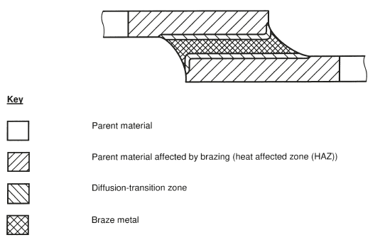 Figure 3-1: Schematic of a brazed and soldered joint (taken from EN ISO 18279:2004)
Principles
General
Brazing is the joining of two materials by the introduction of a liquid metal filler that on solidification holds the two materials together. The parent materials can react with the braze alloy but remain solid during the process. This differs from welding where the parent materials partially melt during the joining operation.
The process of brazing has been in use for several millennia, pictures of craftsmen carrying out brazing operations have been found in an Egyptian tomb from around 1475 BCE. This long history and development as an artisanal skill has resulted in a wide imprecise vocabulary with similar terms having different meanings in multiple languages. For example, by convention, English differentiates between brazing and soldering when the liquidus temperature of the filler is above or below 450°C respectively.
In this standard the term brazing is meant to cover also “soldering” processes with filler materials melting at temperatures lower than 450°C. When the term brazing is used, then this is meant equivalent to soldering in case that the filler materials have liquidus temperature below 450°C.Not all languages make the same distinction. To add to the confusion the filler metal referred to as ‘silver solder’ is in fact a braze alloy and translations of terms such as ‘soft brazing’ and ‘hard brazing’ are also freely used in several languages.
The 450°C boundary in the past was convenient in that it allowed a differentiation between the:
Higher temperature process producing strong structural joints and,
Lower temperature processes used for sealing and joining plumbing joints and now electronic systems.
Although this boundary is still used it is less relevant in modern brazing systems where many lower temperature alloys, for example based on tin or indium, have provided good structural joints in space systems. Soldering for exclusively electronic applications has already been extensively covered by its own standards and will not be covered by this standard.
A significant advantage of brazing is that with the correct selection of process, flux system, braze alloy and joint design, reliable structural joints can be made between almost any combination of parent materials. Within the space industry we have successfully used brazing to make structural joints between metals, ceramics, glasses, ceramic matrix composites (CMCs) and reinforced plastics. Often a brazing process is selected when a joint between complex material combinations is required in difficult environments. As an example, outgassing of brazed systems can be very low simplifying cleanliness aspects.
This standard specifies the necessary requirements to perform brazing for space applications, and is comprised of the following clauses:
Brazing design,
Brazing and inspection personnel,
Equipment and facilities,
Brazing Procedure Specification (BPS),
Brazing inspection,
Joint acceptance criteria,
Brazing process verification,
Flight hardware production,
Quality assurance.
Figure 41 identifies the steps to be taken in order to produce a verified process which can then be used to produce flight hardware.
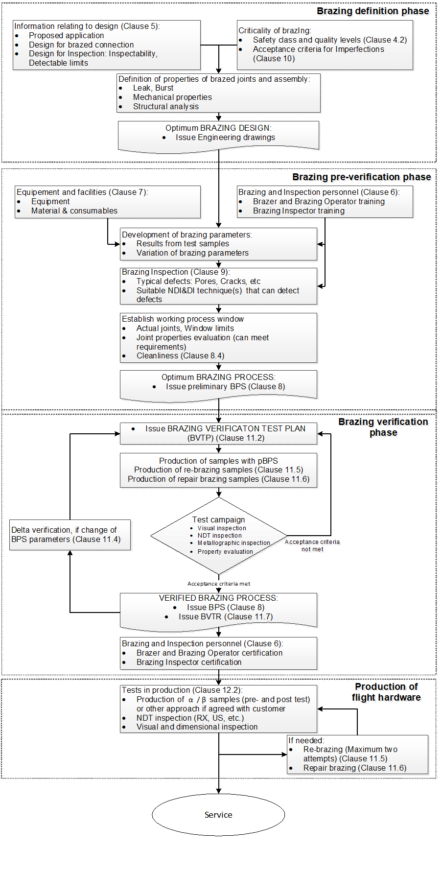 Figure 41: Steps for brazing process verification and flight hardware production
Classification of safety classes and quality levels
Overview
Brazed joints follow the same definition as welded joints for the classification related to safety classes depending on their function. Furthermore, the acceptance criteria for imperfections are by definition of three quality levels.
Safety classes
Class 1 joints are considered critical and structural. Failure of a Class 1 joint results in a loss of spacecraft, major components, loss of life, or loss of control of the spacecraft. Class 1 joints have the highest level of scrutiny in terms of acceptance, which is appropriate to the criticality of performance including internal and external brazing joint integrity verification.
Class 2 joints are non-critical but structural; their failure can reduce the efficiency of the system but not cause the loss of the spacecraft. Class 2 joints require brazing joint integrity verification (either external, internal, or both) appropriate for the intended application.
Class 3 joints are non-critical and non-structural and are contained so that failure does not affect other flight elements. These joints require minimal brazing joint integrity verification, the controls are mainly visual.
For all classes the design and engineering authority has the responsibility to declare a part structural or not.
Quality levels
In brazing joints it is inevitable that some defects and features can be present. The acceptability of such defects or features differ by their nature and size and are assigned for the purpose of quality inspection to three quality acceptance levels (A, B or C) according to the compliance with the component requirement.
Level A represents the more stringent requirements and Level C the least stringent requirements and B is in between A and C.
For the selection of the Quality levels see clause 10.4.
Tailoring of the brazing acceptance criteria
Verification of brazed products takes into account the requirements and acceptance criteria of this standard. If they turn out to be insufficient (or too strict), tailoring can be necessary in agreement with the customer.
Brazing Design
Design for brazed connections
ECSS-Q-ST-70-40_1500001The engineering authority together with the brazing responsible shall select the brazing design.
ECSS-Q-ST-70-40_1500002The engineering authority together with the brazing responsible shall specify the requirements relevant for brazing to ensure compliance with all system and mission requirements.
ECSS-Q-ST-70-40_1500003Brazing Procedure Specification (BPS) specified in clause 8 shall be in compliance with all design requirements.
ECSS-Q-ST-70-40_1500004The engineering authority together with the brazing responsible shall specify controls to demonstrate that brazing joints are satisfying the design requirements.
Directions for design of brazed components can be found in DIN 65169:2017. Brazed and high-temperature brazed components- directions for design.
Design for inspection
ECSS-Q-ST-70-40_1500005Brazing joints classified as Class 1 and Class 2 shall be designed to be inspectable.
ECSS-Q-ST-70-40_1500006Brazing joints shall be designed that excess of filler material is not affecting inspectability of sensitive areas.
ECSS-Q-ST-70-40_1500007In case that Class 1 and Class 2 joints are not inspectable an alternative test shall be agreed with the customer.
Brazing and inspection personnel
Overview
The aim of this clause is to ensure that the brazers have the manual skills and brazing operators and inspectors have the technical knowledge demanded by the brazing operations.
Brazer and brazing operator training
ECSS-Q-ST-70-40_1500008Brazers performing brazing processes requiring manual interaction shall be trained and certified.
ECSS-Q-ST-70-40_1500009The training for manual brazers shall be performed with test pieces according to national and international standards or by an equivalent dedicated training plan established by brazing responsible.
Example of international standards: ISO 11745:2016.
ECSS-Q-ST-70-40_1500010Brazing operators shall be trained to demonstrate compliance to the BPS specified in the clause 8 with specific brazing test piece representative for production part.
ECSS-Q-ST-70-40_1500011The training of the brazers and brazing operator shall be traceable in a written document.
ECSS-Q-ST-70-40_1500012After training, the brazer and brazing operator may operate for a maximum period of two years.
ECSS-Q-ST-70-40_1500013Validity of training may be extended indefinitely provided the two following conditions are met:
- A record is maintained from the date of the initial training,
- Brazer and brazing operator use the process at least once every six months from initial training.
Brazing inspector training
ECSS-Q-ST-70-40_1500014Brazing inspectors shall be nominated by the company with involvement of quality assurance responsible.
ECSS-Q-ST-70-40_1500015Brazing inspectors shall be trained for this standard and the specific BPS with the involvement of the brazing responsible.
Equipment and facilities
Equipment
ECSS-Q-ST-70-40_1500016All equipment used for brazing shall be subject to testing, inspection and maintenance in accordance with the requirements of the equipment manufacturer and the process necessities.
ECSS-Q-ST-70-40_1500017When there is no period for the inspection and maintenance defined, inspection and maintenance shall be performed at least every 12 months.
Materials and consumables
Filler material
ECSS-Q-ST-70-40_1500018Filler metals shall be procured according to clause 5.6 of ECSS-Q-ST-70.
Filler materials are specified for example in EN ISO 17672:2016.
Flux
ECSS-Q-ST-70-40_1500019Flux shall be procured according to clause 5.6 of ECSS-Q-ST-70.
Flux materials are specified for example in 1045:1997.
Tooling and fixtures
ECSS-Q-ST-70-40_1500020Only the tooling and fixtures specified in the BPS in Annex A shall be used for the brazing operation.
Change of tooling can have impact on brazing joints. This can be e.g. because of different coefficients of thermal expansion impacting directly the solder gap and capillary effects and thus brazing joint quality.
ECSS-Q-ST-70-40_1500021Tooling and fixtures shall be checked for cleanliness to comply with requirements from the clause 8.4.
Brazing procedure specification (BPS)
General
ECSS-Q-ST-70-40_1500022A Brazing Procedure specification shall be written in accordance with DRD in Annex A.
ECSS-Q-ST-70-40_1500023A BPS specified in requirement 8.1a shall be established for each type of brazed joint in a space application.
ECSS-Q-ST-70-40_1500024All brazing joints shall be in conformance with the BPS specified in the DRD in the Annex A.
Drawing
ECSS-Q-ST-70-40_1500025Features for all brazing joints shall be specified either on the engineering drawing or in supporting documentation.
ECSS-Q-ST-70-40_1500026The information related to the brazing on the drawing shall be in conformance with BPS from DRD in Annex A.
A template for a table of brazing details can be similar as shown for welding in DIN 65118:2010.
ECSS-Q-ST-70-40_1500027The drawing shall contain the BPS-reference.
Process description
ECSS-Q-ST-70-40_1500028The minimum of documentation for process description shall be in conformance with information required from DRD in Annex A.
Cleanliness aspects of Brazing
Overview
Brazing processes can be source of particular and molecular contamination.
Requirements
ECSS-Q-ST-70-40_1500029To minimise the contribution to the contamination budget during brazing, the following requirements shall apply for operators and other personnel involved in the brazing process:
- When brazing is in a clean room: use only nitrile gloves,
- When brazing is outside a clean room: wear lint free clothing and lint free gloves for assembly and brazing of flight hardware,
- Ensure that tooling and fixtures are not a source of contamination to the brazed hardware,
- Remove corrosive residues from brazing process.
To avoid cross-contamination it is good practice that the molecular and particular cleanliness of tooling and fixtures is at least same level as the brazed H/W. In addition, contaminants transfer mechanisms depending on the used process are considered, for example from outgassing and condensation during vacuum brazing.
ECSS-Q-ST-70-40_1500030After brazing, the brazed parts shall be cleaned as specified in the BPS.
Brazing inspection
Non-destructive testing
ECSS-Q-ST-70-40_1500031The selected NDT method shall be able to detect the compliance with the defined acceptance criteria.
ECSS-Q-ST-70-40_1500032NDT method shall be selected from the following list:
- Visual examination;
- Ultrasonic examination;
- Radiographic examination;
- Leak testing;
- Proof testing;
- Thermography.
- 1 For example use methods in accordance with ECSS-Q-ST-70-15 and EN12799:2000.
- 2 Visual inspection of brazing joints is described in the DIN ISO 19828:2021.
ECSS-Q-ST-70-40_1500033Any acceptance criteria for the NDT, not covered in clause 10.3, shall be agreed with the customer.
Destructive testing
ECSS-Q-ST-70-40_1500034The selected destructive test-method shall be able to demonstrate the compliance with the acceptance criteria from clause 10.
ECSS-Q-ST-70-40_1500035For destructive testing the test method shall be selected from the following list:
- Shear test,
- Tensile test,
- Metallographic examination,
- Hardness testing,
- Peel testing,
- Bend testing,
- Burst test.
For example use methods in accordance with EN12797:2000.
Brazing acceptance criteria
General
ECSS-Q-ST-70-40_1500036The baseline acceptance criteria for brazing joints shall be in conformance with the requirements of clause 10.3, except cases specified in the requirements 10.1b and 10.1c.
ECSS-Q-ST-70-40_1500037In case the brazing acceptance criteria are different to that specified in the requirements of clause 10.3, an RfA shall be raised.
ECSS-Q-ST-70-40_1500038For imperfections that are not covered by requirements specified in 10.2, the brazing acceptance criteria shall be agreed with the customer.
Active brazing can produce features looking like local melting. This is not an imperfection in the context of this brazing method.
Classification of Imperfections
ECSS-Q-ST-70-40_1500039The imperfections in brazing joints shall be classified into groups as follows:
- Group I: Cracks,
- Group II: Cavities,
- Group III: Solid inclusions,
- Group IV: Bonding imperfections,
- Group V: Shape and size imperfections,
- Group VI: Miscellaneous imperfections.
The classification is derived from EN ISO 18279:2004.
Brazing Imperfections Acceptance Criteria
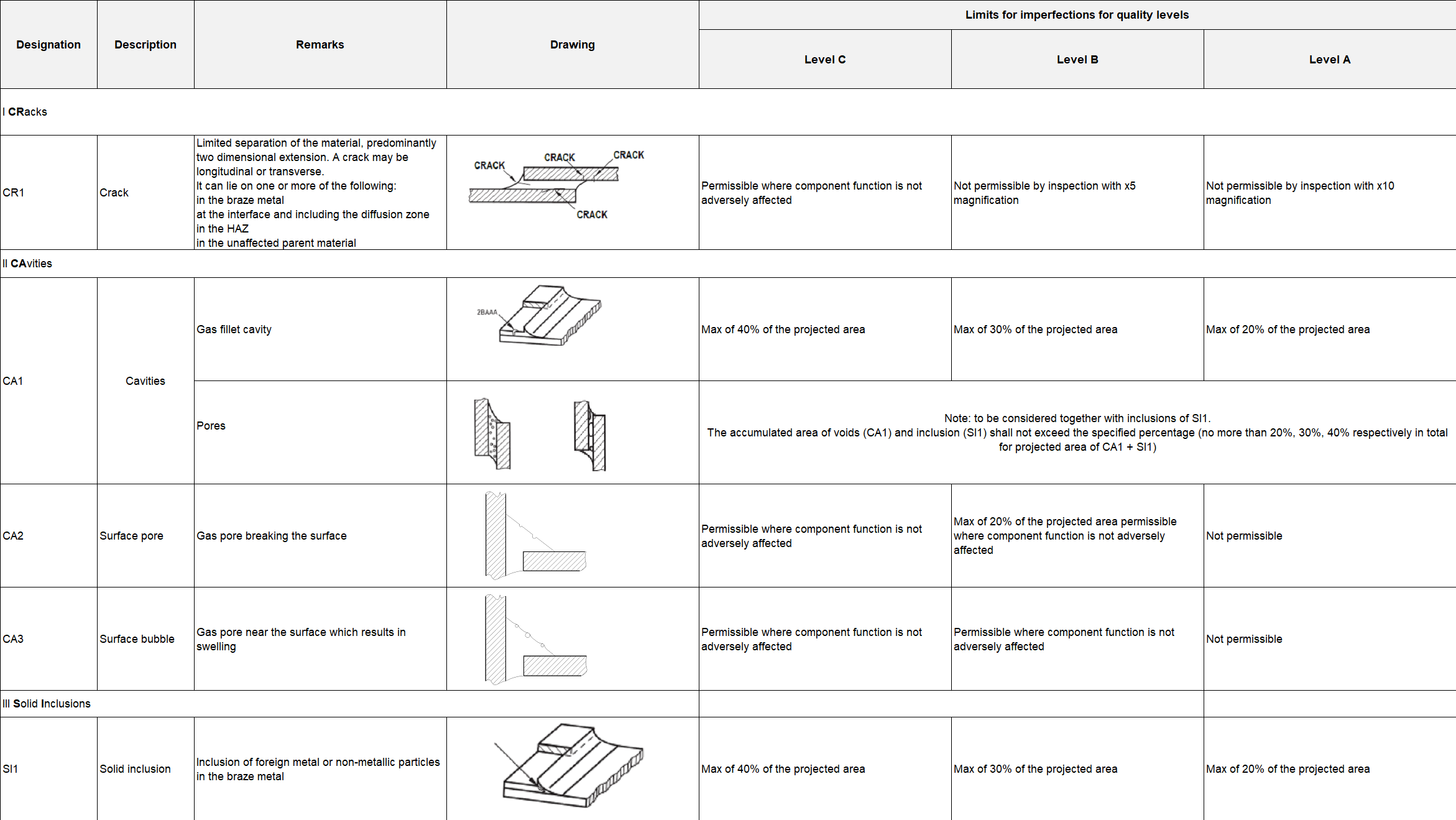
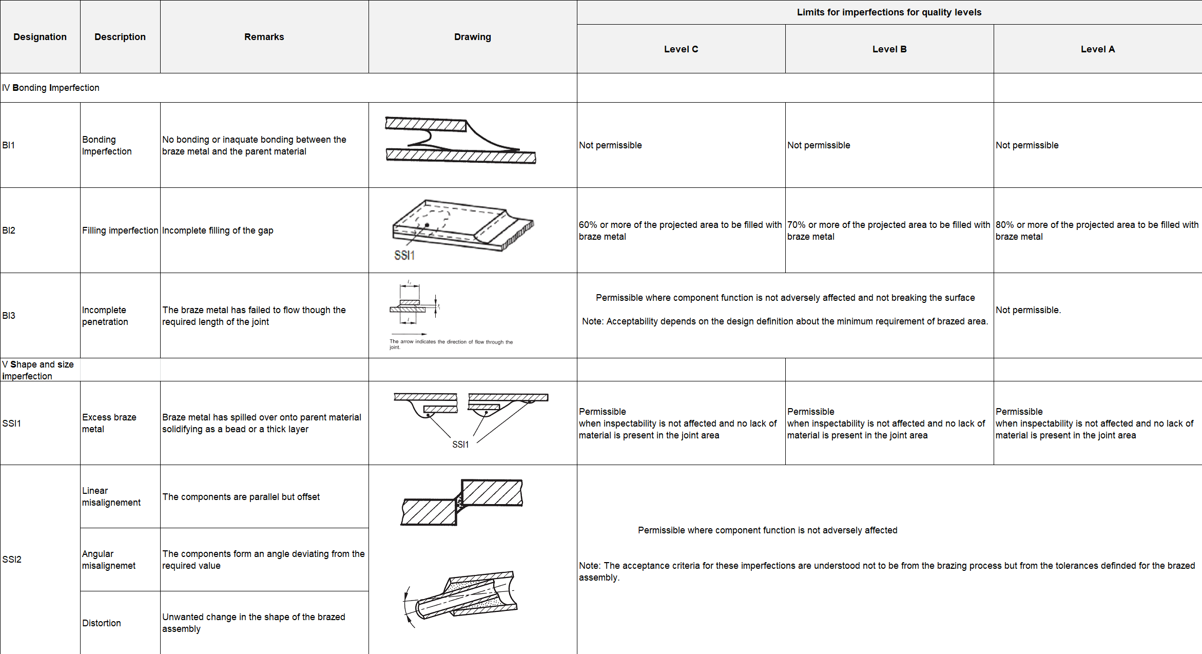
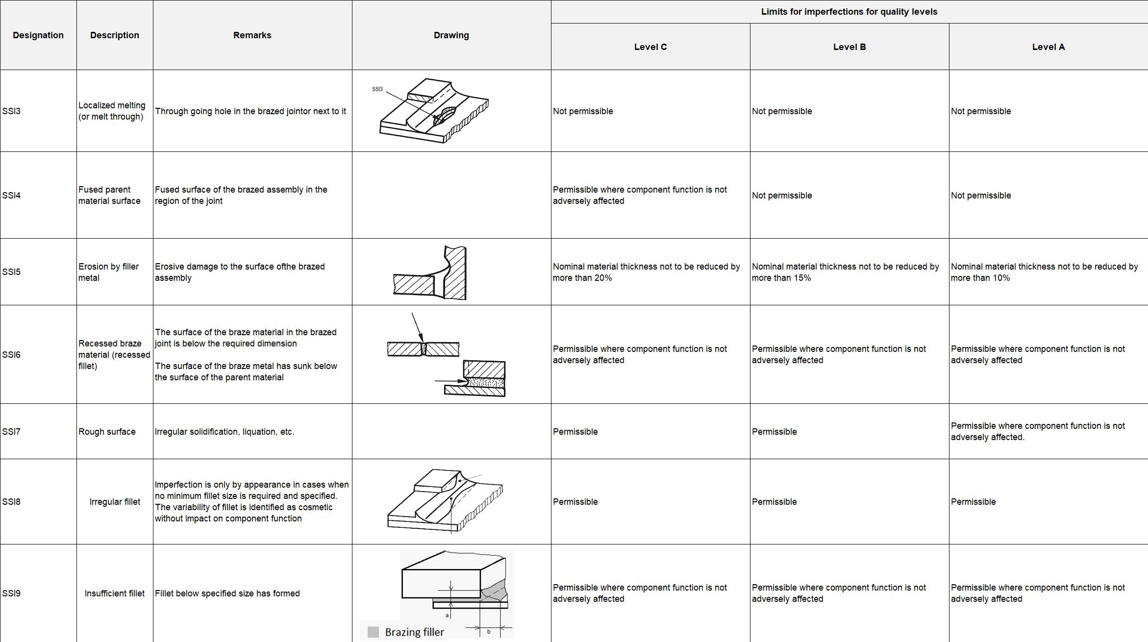
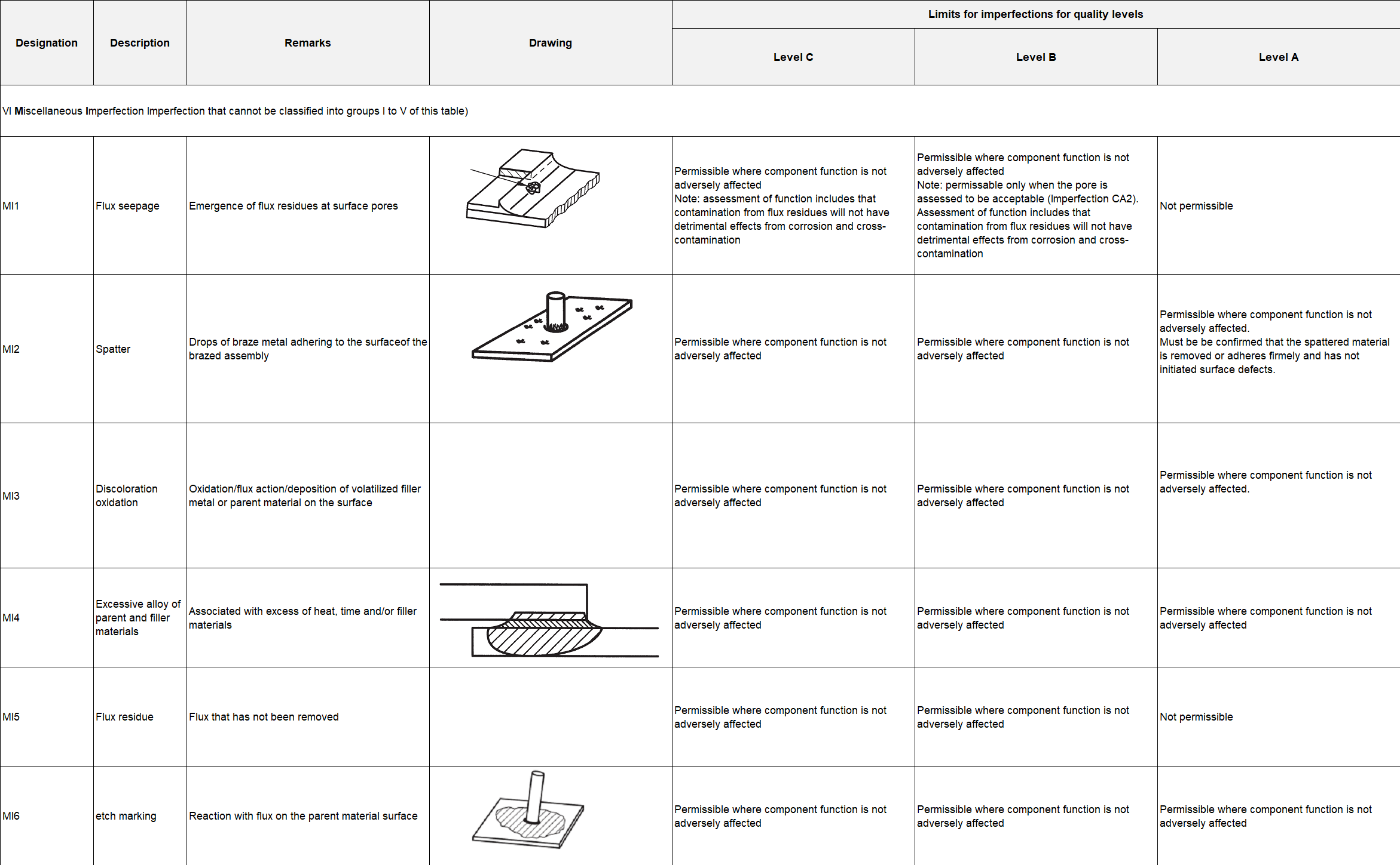
ECSS-Q-ST-70-40_1500040The acceptance criteria for brazed joints, specified in Table 101, shall be applied.
ECSS-Q-ST-70-40_1500041Limits specified in Table 101 shall be used in absence of other application specific definition agreed with the customer.
The evaluation of brazed joints in Table 101 is derived from the EN ISO 18279:2004 Table B.1 "Quality levels for brazed joints imperfections”.
Selection of quality levels
ECSS-Q-ST-70-40_1500042For the selection of the quality levels from Table 101 the following rule shall apply:
- For Safety Class 1: Quality Level A,
- For Safety Class 2: Quality Level B as a minimum,
- For Safety Class 3: Quality Level C as a minimum. ECSS-Q-ST-70-40_1500043Table 101: Classification of imperfections in Brazing joints(the classification of imperfections is derived from EN ISO 18279:2004)
Brazing process verification
General
For the Brazing Procedure verification the preliminary BPS is used to produce test samples which are then tested to demonstrate compliance with the mission requirements. It is important to recognize that the form and size of the test pieces in brazing has impact on the service properties which are seldom observed in welding. Welded specimen beyond a certain minimum size have similar properties and for that reason welding procedures can be verified more general for range of different joints. Specific consideration is required when dissimilar materials with significantly different CTEs are brazed. The thermo-elastic stress from CTE-mismatch can prevent successful brazing depending on the assembly.
In some cases it is possible to use standard test pieces to demonstrate all joint properties relevant for the application. Tests on standardized test specimen aim to produce standardized and comparable results of the brazing joint.
To consider the size- and shape dependent properties in brazing, the verification of a brazing process needs taking into account also the application specific requirements related to on-ground storage, launch loads, environmental conditions. For that reason standard tests and test specimen are not sufficient but specific tests and test sample definition is needed for brazing process verification.
Brazing Verification Test Plan
ECSS-Q-ST-70-40_1500044A Brazing Verification Test Plan (BVTP) shall be issued for brazing procedure verifications according to the DRD in Annex B.
ECSS-Q-ST-70-40_1500045The test sequence shall be selected with consideration of the reliability under application loads and mission environmental condition.
ECSS-Q-ST-70-40_1500046In case that there are no specific brazing joint tests defined, standard tests with standard test specimen shall be planned.
A test matrix of standard test can be found in Table 111.
ECSS-Q-ST-70-40_1500047In case of specific requirements from the application, specific test shall be planned to verify compliance.
Examples of specific tests are Leak Test, Pressure Test, Noise and Vibration Test, Creep, Fatigue, Corrosion.
ECSS-Q-ST-70-40_1500048In case that the brazed assembly is under thermo-elastic stress, specimen representative for the brazed assembly shall be defined.
ECSS-Q-ST-70-40_1500049Test specimen from the requirement 11.2e shall be submitted to thermal cycling in the test sequence.
ECSS-Q-ST-70-40_1500050Pass-Fail criteria of the verification test sequence shall be specified in the Test Plan.
Table 111: Test Matrix for standard test
|
Type of test
|
Sample Number
| ||||
|
Inspection
|
1
|
2
|
3
|
4
|
5
|
|
Visual Inspection
|
X
|
X
|
X
|
X
|
X
|
|
Radiographic Testing
|
X
|
X
|
X
|
X
|
X
|
|
Metallography and Hardness
|
X
|
|
|
|
X
|
|
Mechanical Tests
|
|
X
|
X
|
X
|
|
Completion of verification
ECSS-Q-ST-70-40_1500051The samples shall be marked and serialised.
ECSS-Q-ST-70-40_1500052In the case when at least one measurement on one sample is non-compliant with the requirements of clause 11, the verification shall be rejected.
Delta verification
ECSS-Q-ST-70-40_1500053In case one or more parameters in an approved BPS are changed outside the allowed range, a delta verification shall be performed.
ECSS-Q-ST-70-40_1500054The decision to perform a delta verification or a complete verification shall be under the responsibility of the brazing responsible.
ECSS-Q-ST-70-40_1500055Every change in the existing brazing configuration shall be agreed with the customer to specify if a re-verification or delta verification is necessary.
Re-brazing, in-process correction
ECSS-Q-ST-70-40_1500056After the brazing operation has been completed, visual examination shall be performed by the brazing operator and the brazing inspector.
ECSS-Q-ST-70-40_1500057Re-brazing shall be verified using the same method as for verification.
ECSS-Q-ST-70-40_1500058Two additional brazing shall be produced in the brazing verification phase for re-brazing.
ECSS-Q-ST-70-40_1500059In case defects are observed, then a maximum of two attempts may be made for in-process correction.
ECSS-Q-ST-70-40_1500060The use of in-process correction shall be documented in the inspection report and shop traveller.
ECSS-Q-ST-70-40_1500061In case the two re-brazing attempts cannot result in the required level of in process correction, the following shall be performed:
- A NCR is raised in conformance with requirements from clause 5 of ECSS-Q-ST-10-09.
- Repair brazing is performed in accordance with the requirements from clause 11.6.
Repair-brazing
ECSS-Q-ST-70-40_1500062Repair-brazing shall only performed following the raising of an NCR in conformance with requirements from clause 5 of ECSS-Q-ST-10-09.
Reason for repair can be for example that 2 re-brazing attempts have not been successful, the use of wrong filler metal or flux, or when a re-braze extends outside the original brazing zone.
ECSS-Q-ST-70-40_1500063Repair-brazing shall be performed using a BPS which is approved for brazing repair.
ECSS-Q-ST-70-40_1500064Re-inspection of all repaired brazing areas shall be performed using the same methods and requirements as the original brazing.
ECSS-Q-ST-70-40_1500065For multiple repair-brazing, it shall be demonstrated that design strength requirements are met in any given area.
Documentation
ECSS-Q-ST-70-40_1500066For the verification of the brazing process, the following documents shall be issued:
- Brazing Verification Test Plan (BVTP) in conformance with the DRD from Annex B.
- Brazing Verification Test Report (BVTR) in conformance with Test Report DRD from Annex C of ECSS-E-ST-10-02.
- Brazing Procedure Specification (BPS) in conformance with the DRD from Annex A for every dimension and material combination.
ECSS-Q-ST-70-40_1500067Tailoring of the BVTP for other tests shall be agreed with the supplier and customer.
ECSS-Q-ST-70-40_1500068Documents specified in the requirements from 11.7a.1 to 11.7a.3 and 11.7b shall be controlled in conformance with ECSS-M-ST-40.
Flight hardware production
Documentation
ECSS-Q-ST-70-40_1500069Prior to the start of manufacturing the following documents shall be made available:
- BVTR,
- Complete set of drawings,
- BPS from DRD of Annex A.
ECSS-Q-ST-70-40_1500070Any brazing performed on flight hardware shall be in conformance with the approved BPS.
ECSS-Q-ST-70-40_1500071Any brazing performed on flight hardware shall be performed under configuration control.
Requirements for flight hardware brazing
General
ECSS-Q-ST-70-40_1500072The preparation of a shop traveller shall be completed.
ECSS-Q-ST-70-40_1500073Only approved BPS shall be used for the brazing of flight hardware.
ECSS-Q-ST-70-40_1500074During brazing of flight hardware, the cleanliness requirements of clause 8.4 shall apply.
Extent of testing to support flight hardware production
ECSS-Q-ST-70-40_1500075Prior to flight hardware production, application of Alpha and Beta samples or alternative brazing control technique in compliance with the Table 121 shall be agreed with the customer.
ECSS-Q-ST-70-40_1500076Techniques specified in the requirement 12.2.2a shall be:
- Demonstrated during verification, and
- Results approved by the customer. ECSS-Q-ST-70-40_1500077Table 121: Tests to be performed on parts performed during production of flight hardware
|
Safety Class
|
Visual and Dimensional Inspection
|
Radiographic or Ultrasonic Inspection**
|
|
Class 1
|
100 %
|
100 %
|
|
Class 2
|
100 %
|
*
|
|
Class 3
|
100 %
|
*
|
|
*NOTE: NDT inspection for Class 2 and Class3 brazing joints as appropriate for intended use
| ||
Quality assurance
Maintenance of BPS
ECSS-Q-ST-70-40_1500078All changes to the BPS from DRD from Annex A shall be controlled in conformance with the ECSS-M-ST-40.
ECSS-Q-ST-70-40_1500079As a result of modifications to the brazing process specified in the requirement 13.1a, the BPS from DRD from Annex A shall be updated.
For example, changes to the jigs, parameter changes.
ECSS-Q-ST-70-40_1500080Modifications to brazing parameters which fall outside the BPS shall lead to the issue of a new brazing configuration.
ECSS-Q-ST-70-40_1500081In case of an issue of a new brazing configuration specified in the requirement 13.1c the existing brazing configuration shall become obsolete.
Quality control
Documentation of brazing parameters
ECSS-Q-ST-70-40_1500082The data generated during mechanised brazing shall be recorded.
ECSS-Q-ST-70-40_1500083All mechanised brazing data shall be available for review.
Anomalies and nonconformances occurring during the brazing process
ECSS-Q-ST-70-40_1500084In case of anomalies occurring during the brazing process, leading to the brazing activities to be stopped in a controlled manner, the brazing operators shall inform the brazing responsible.
An unexpected change in one or more process parameters can be considered as anomalies.
ECSS-Q-ST-70-40_1500085For Safety Classes 1 and 2, all anomalies identified in compliance with the requirement 13.2.2a shall be classified as major, and a major NCR in conformance with clause 5 of ECSS-Q-ST-10-09 be raised.
ECSS-Q-ST-70-40_1500086For Safety Class 3, depending on the anomaly identified from the requirement 13.2.2a being minor or major, an NCR shall be raised as minor or major in conformance with clause 5 of ECSS-Q-ST-10-09 accordingly.
ECSS-Q-ST-70-40_1500087Malfunctions of the brazing equipment shall be documented in the maintenance book.
ECSS-Q-ST-70-40_1500088Malfunctions of the brazing equipment shall be reported to the brazing responsible.
ECSS-Q-ST-70-40_1500089A NCR shall be raised in case a flight part is affected by the equipment malfunction.
ECSS-Q-ST-70-40_1500090All the major and minor anomalies shall be recorded and made available for the customer to review upon request.
Inspection and test methods
ECSS-Q-ST-70-40_1500091Inspection shall be performed on brazing joints to demonstrate compliance with the requirements from the clauses 9.1 and 9.2.
ECSS-Q-ST-70-40_1500092Any nonconformance shall be recorded in compliance with clause 5 of ECSS-Q-ST-10-09 and made available to the customer.
ANNEX(normative)Brazing Procedure Specification (BPS) - DRD
DRD identification
Requirement identification and source document
This DRD is called from ECSS-Q-ST-70-40, requirement 8.1a.
Purpose and objective
The purpose of the Brazing Procedure Specification is to ensure that all relevant information relating to the brazing process is documented in sufficient detail such that this information can be subsequently used to reproduce the brazing joint.
Expected response
Scope and content
General
ECSS-Q-ST-70-40_1500093The BPS shall include the date, issue and revision number.
ECSS-Q-ST-70-40_1500094The BPS shall contain the following information:
- Brazing process steps,
- Brazing process parameters,
- Parent material,
- Filler and Flux,
- Joint type,
- Cleaning procedure,
- Mechanical or thermal treatment before and after brazing,
- Quality level for imperfections acceptance criteria,
- Inspection steps. Manufacturer
ECSS-Q-ST-70-40_1500095The BPS shall define the manufacturer as follows:
Identification of the lower tier supplier who performs the brazing,
Reference to the BVTR or other applicable documents.
Equipment
ECSS-Q-ST-70-40_1500096The BPS shall include the identification of the equipment, model and serial number, used to perform the brazing.
Tooling and fixtures
ECSS-Q-ST-70-40_1500097The BPS shall specify the tooling and fixtures used to perform the brazing.
Non-destructive inspection
ECSS-Q-ST-70-40_1500098The BPS shall specify all non-destructive inspection techniques.
Special remarks
None.
ANNEX(normative)Brazing Verification Test Plan (BVTP) - DRD
DRD identification
This DRD is called from the ECSS-Q-ST-70-40, requirement 11.7a.1.
Purpose and scope
The purpose of the brazing verification test plan (BVTP) is to ensure that all relevant information relating to the test plan is documented in sufficient detail such that this information can be subsequently used to produce the required results.
Expected response
Scope and content
General
ECSS-Q-ST-70-40_1500099The BVTP shall include the date, issue and revision number.
ECSS-Q-ST-70-40_1500100The BVTP shall include the following information:
- Brazing process,
- Parent material combination,
- Filler material and Flux,
- Joint type,
- Cleaning procedure,
- Types of test for the brazing verification,
- Number and type of samples to be tested,
- Criteria of acceptance of a brazing joints.
Special remarks
None.
Bibliography
|
ECSS-S-ST-00
|
ECSS system – Description, implementation and general requirements
|
|
ECSS-Q-ST-70-15
|
Space product assurance – Non-destructive testing
|
|
DIN 65118:2010
|
Welding in Aerospace – Indication in design documents and general design requirements
|
|
DIN 65169:2017
|
Aerospace – Brazed and high-temperature brazed components – Directions for design
|
|
DIN EN 1045:1997
|
Fluxes for brazing – Classification and technical delivery conditions
|
|
DIN ISO 19828:2021
|
Welding for aerospace applications – Visual inspection of welds
|
|
EN 12797:2000
|
Destructive tests on brazed joints
|
|
EN 12799:2000
|
Non-destructive examination of brazed joints
|
|
EN ISO 17672:2016
|
Brazing – Filler metals
|
|
EN ISO 18279:2004
|
Imperfections in brazed joints
|
|
ISO 11745:2016
|
Brazing for aerospace applications – Qualification test for brazer and brazing operators – Brazing of metallic components
|