
Space engineering
Telemetry and telecommand packet utilization
Foreword
This Standard is one of the series of ECSS Standards intended to be applied together for the management, engineering and product assurance in space projects and applications. ECSS is a cooperative effort of the European Space Agency, national space agencies and European industry associations for the purpose of developing and maintaining common standards. Requirements in this Standard are defined in terms of what shall be accomplished, rather than in terms of how to organize and perform the necessary work. This allows existing organizational structures and methods to be applied where they are effective, and for the structures and methods to evolve as necessary without rewriting the standards.
This Standard has been prepared by the ECSS-E-ST-70-41C Working Group, reviewed by the ECSS Executive Secretariat and approved by the ECSS Technical Authority.
Disclaimer
ECSS does not provide any warranty whatsoever, whether expressed, implied, or statutory, including, but not limited to, any warranty of merchantability or fitness for a particular purpose or any warranty that the contents of the item are error-free. In no respect shall ECSS incur any liability for any damages, including, but not limited to, direct, indirect, special, or consequential damages arising out of, resulting from, or in any way connected to the use of this Standard, whether or not based upon warranty, business agreement, tort, or otherwise; whether or not injury was sustained by persons or property or otherwise; and whether or not loss was sustained from, or arose out of, the results of, the item, or any services that may be provided by ECSS.
Published by: ESA Requirements and Standards Division ESTEC, P.O. Box 299, 2200 AG Noordwijk The NetherlandsCopyright: 2016© by the European Space Agency for the members of ECSS## Change log
|
ECSS-E-70-41A
|
First issue
|
|
ECSS-E-70-41B
|
never issued
|
|
ECSS-E-ST-70-41C
|
Second issue
|
Introduction
The CCSDS Space Packet Protocol (CCSDS 133.0-B-1) and the ECSS-E-ST-50 series of standards address the end-to-end transport of telemetry and telecommand data between user applications on the ground and application processes on-board the spacecraft, and the intermediate transfer of these data through the different elements of the ground and space segments.
This packet utilization standard (PUS) complements those standards by defining the applicationlevel interface between ground and space, in order to satisfy the requirements of electrical integration and testing and flight operations.
Scope
This Standard addresses the utilization of telecommand packets and telemetry packets for the purposes of remote monitoring and control of spacecraft subsystems and payloads.
This Standard does not address missionspecific payload data packets, but the rules contained herein can be extended to suit the requirements of any mission.
This Standard does not address audio and video data as they are not contained within either telecommand or telemetry packets.
This Standard defines a set of services that satisfy all the fundamental operational requirements for spacecraft monitoring and control during spacecraft integration, testing and flight operations, refer to ECSS-E-ST-70-11. It also specifies the structure and contents of the telecommand packets used to transport the requests and the telemetry packets used to transport the reports.
This Standard can be used by any mission, no matter what its domain of application, orbit or ground station coverage characteristics. However, it is not the intention that the PUS should be applied in its entirety to a given mission. The services defined in this Standard cover a wide spectrum of operational scenarios and, for a given mission, only a subset of these services is likely to be appropriate.
Choices are made early in the design phase of a new mission resulting in the need to tailor the PUS to suit the requirements of that mission. These choices include:
the on-board system design and architecture, in terms of the number of on-board application processes, their on-board implementation (e.g. the allocation to on-board processors) and their roles (i.e. which functions or subsystems or payloads they support);
which PUS services are supported by each application process.
Each mission usually documents the results of this design and selection process in a "Space-to-Ground Interface Control Document".
Some missions implement a centralized architecture with a small number of application processes, whilst others have a highlydistributed architecture within which a correspondingly larger number of application processes are distributed across several on-board processors.
The specification of services in this Standard is adapted to the expectation that different missions require different levels of complexity and capability from a given service. To this end, all services are optional and a given service can be implemented at one of several distinct levels, corresponding to the inclusion of one or more capability sets. The minimum capability set corresponds to the simplest possible level that also remains sensible and coherent. At least this set is included in every implementation of a given service.
The standardized PUS services fulfil the following criteria:
Commonality: each standard service corresponds to a group of capabilities applicable to many missions.
Coherence: the capabilities provided by each standard service are closely related and their scope is unambiguously specified. Each standard service covers all the activities for managing interrelated state information and all activities that use that state information.
Self-containment: each standard service has minimum and well-defined interactions with other services or on-board functions.
Implementation independence: the standard services neither assume nor exclude a particular spacecraft architecture (hardware or software).
This Standard mainly addresses the requirements that apply to the spacecraft and its components. The ground segment counterpart requirements related to the testing or the operations of the spacecraft and its components can be derived from these requirements and are not specified in this Standard. Tailoring the PUS for a mission is mainly a task for the operations team and the spacecraft manufacturer. This Standard assumes that the mission ground segment used to test or operate the spacecraft implements all standardized capabilities and as such, does not further constrain the mission tailoring process of these capabilities.
The PUS should be viewed as a "Menu" from which the applicable services and servicelevels are selected for a given mission. This selection process is repeated for each on-board application process, since each application process is designed to provide a specific set of tailored services.
This standard may be tailored for the specific characteristics and constraints of a space project in conformance with ECSS-S-ST-00.
This Standard does not include any protection against inadequate operations. This is considered mission specific.
Normative references
The following normative documents contain provisions which, through reference in this text, constitute provisions of this ECSS Standard. For dated references, subsequent amendments to, or revision of any of these publications do not apply. However, parties to agreements based on this ECSS Standard are encouraged to investigate the possibility of applying the more recent editions of the normative documents indicated below. For undated references, the latest edition of the publication referred to applies.
|
ECSS-S-ST-00-01
|
ECSS system – Glossary of terms
|
|
ECSS-E-ST-70
|
Space engineering – Ground systems and operations
|
|
ECSS-E-ST-70-01
|
Space engineering – Spacecraft on-board control procedures
|
|
ECSS-E-ST-70-11
|
Space engineering – Space segment operability
|
|
ECSS-E-ST-70-31
|
Space engineering – Ground systems and operations – Monitoring and control data definition
|
|
CCSDS 133.0-B-1, September 2003
|
Space Packet Protocol, Blue Book
|
|
CCSDS 301.0-B-4, November 2010
|
Time Code Formats, Blue Book
|
Terms, definitions and abbreviated terms
Terms from other standards
For the purpose of this Standard, the terms and definitions from ECSS-S-ST-00-01 apply, in particular for the following terms:
space system
space segment
spacecraft
ground segment
Terms specific to the present standard
acceptance notification
notification that is generated by the acceptance and reporting subservice provider of the application process that hosts the subservice provider in charge of executing the related request
acceptance verification report
report generated by the acceptance and reporting subservice provider as a consequence of a request acceptance verification
The acceptance and reporting subservice for a request is hosted by the application process that hosts the subservice responsible for executing that request. Each acceptance verification report is reporting either the successful acceptance of a request or the failed acceptance. In case of successful acceptance, the request is sent to the subservice provider in charge of its execution. In case of failed acceptance, the request is rejected and as such, not sent to any subservice provider.
application process
element of the space system that can host one or more subservice entities
An application process resides either on-board or on ground. An on-board application process usually hosts some subservice providers but can also host some subservice users. A ground application process usually hosts some subservice users. If a ground application process is remotely controlled by the ground monitoring and control system, that application process behaves as an on-board application process and can host some subservice providers.
capability
functionality of a service or a subservice
A capability is specified by a set of operational requirements for a function of the overall space system that can be remotely controlled by the ground monitoring and control system or by other on-board applications. This Standard mainly addresses these remote controlled related requirements and especially those applicable to the subservice providers.
data report
report generated by a subservice provider as part of the subservice functionality
A data report can be generated in response to a request or to an instruction to elicit some specific service data. A data report can also be generated autonomously, when reports are enabled by a request, or as part of a continuous reporting functionality.
event report
report related to an occurrence of an event
Event reports are generated by the subservice providers.
execution notification
notification that is generated by the subservice provider in charge of execution of the related instruction
An execution notification reports on the successful or failed execution of an instruction. This Standard does not specify how the notifications are implemented on-board, nor how the subservice providers in charge of their generation interact with the subservice providers in charge of generating the corresponding execution verification reports.
execution verification report
report generated by the execution reporting subservice provider of an application process as a consequence of the reception of one or more execution notifications
The execution reporting subservice for a request is hosted by the application process that hosts the subservice responsible for executing that request. Each execution verification report is reporting either a successful or a failed execution stage (start, progress or completion) of a request.
instruction
elementary constituent of a request that is generated by a subservice user for execution by a subservice provider
message
request or report
notification
elementary constituent of a report than is generated by a subservice provider for interpretation by a subservice user
object path
combination of a repository path and a file name or directory name
on-board file system
system used to control data organised in files
on-board memory
logical memory space
The on-board memories can potentially be managed by different on-board processors. The mapping between the on-board memories and the physical memories is out of the scope of this Standard.
on-board parameter
lowest level of elementary data item on-board
A parameter has a unique interpretation.
report
message made of one or more notifications generated by a subservice provider for interpretation by a subservice user
This Standard identifies three types of reports:
- verification reports,
- data reports, and
- event reports.
repository path
logical path to where a file or a directory is located
A repository path can either represent a physical path such as a directory path within a file system or a logical path such as a mounted device (e.g. "/mm1"pointing to a mass memory device), a directory within a mounted device (e.g. "/mm1/dir1").
request
message consisting of one or more instructions generated by a subservice user for execution by a subservice provider
routing notification
notification that is generated by a routing and reporting subservice provider as a consequence of a request routing verification
routing verification report
report generated by a routing and reporting subservice provider as a consequence of a request routing verification
The routing verification reports are generated by the application processes that are involved in the routing of a request between a subservice user and a subservice provider. The routing and reporting subservice generates a failed routing verification report to inform a subservice user of the impossibility of pursuing the routing of the request, e.g. because of corruption of that request during the routing.
service
functional element of the space system that provides a number of closely-related functions that can be remotely operated
Each service is composed of one or more subservices, where each subservice involves a subservice provider and one or more subservice users. A subservice provider is in charge of performing some space system functions. A subservice user is in charge of issuing requests for the execution of those functions and of processing the resulting feedback.
subservice
elementary constituent of a service composed of exactly one subservice provider and the related subservice users that are interacting through dedicated sets of messages
subservice entity
operational element of a subservice hosted by an application process that acts as subservice user or subservice provider
subservice provider
operational element of a subservice that is in charge of execution of the subservice requests and generation of the subservice reports
subservice user
operational element of a subservice that is in charge of initiating the subservice requests and processing the subservice reports
transaction
set of messages related to the execution of exactly one capability which are exchanged between a subservice user and a subservice provider
The different types of transactions defined in this Standard are:
- request related transaction,
- autonomous data reporting transaction, and
- event reporting transaction.
verification report
routing, acceptance or execution verification report
Abbreviated terms
For the purpose of this Standard, the abbreviated terms from ECSS-S-ST-00-01 and the following apply:
|
Abbreviation
|
Meaning
|
|
ANSI
|
American National Standards Institute
|
|
AOCS
|
attitude and orbit control subsystem
|
|
APID
|
application process identifier
|
|
ASCII
|
American standard code for information interchange
|
|
CCSDS
|
Consultative Committee for Space Data Systems
|
|
CDS
|
CCSDS day segmented
|
|
CPDU
|
command pulse distribution unit
|
|
CRC
|
cyclic redundancy code
|
|
CUC
|
CCSDS unsegmented code
|
|
ESA
|
European Space Agency
|
|
FDIR
|
fault, diagnostic, isolation and recovery
|
|
FMON
|
functional monitoring
|
|
GPS
|
global positioning system
|
|
ID
|
identifier
|
|
IEEE
|
Institute of Electrical and Electronics Engineers
|
|
ISO
|
International Organization for Standardization
|
|
LSB
|
less significant bit
|
|
MAP
|
multiplexer access point
|
|
MIL-STD
|
United States military standard
|
|
MSB
|
most significant bit
|
|
OBCP
|
on-board control procedure
|
|
PCS
|
packet check sequence
|
|
PFC
|
packet field format code
|
|
PMON
|
parameter monitoring
|
|
PTC
|
packet field type code
|
|
PUS
|
packet utilization standard
|
|
RAM
|
random access memory
|
|
ST
|
service type
|
|
TAI
|
international atomic time
|
|
TC
|
telecommand
|
|
TM
|
telemetry
|
|
UTC
|
coordinated universal time
|
NomenclatureThe following nomenclature applies throughout this document:The word “shall” is used in this Standard to express requirements. All the requirements are expressed with the word “shall”.
The word “should” is used in this Standard to express recommendations. All the recommendations are expressed with the word “should”.
It is expected that, during tailoring, recommendations in this document are either converted into requirements or tailored out.
The words “may” and “need not” are used in this Standard to express positive and negative permissions, respectively. All the positive permissions are expressed with the word “may”. All the negative permissions are expressed with the words “need not”.
The word “can” is used in this Standard to express capabilities or possibilities, and therefore, if not accompanied by one of the previous words, it implies descriptive text.
In ECSS “may” and “can” have completely different meanings: “may” is normative (permission), and “can” is descriptive.
The present and past tenses are used in this Standard to express statements of fact, and therefore they imply descriptive text.
Context and background
Introduction
This Standard addresses the need to standardize the way the space system functions are defined when involved in an interaction between space and ground.
This Standard introduces the concept of PUS services, consisting of PUS subservices. The services and subservices formalise the closely related and self-contained set of space system functions and all related entities and interaction artifacts.
Each PUS subservice is composed of PUS subservice entities, each one playing either the role of a subservice provider or the role of a subservice user. Each PUS subservice entity is hosted by an application process on-board or on-ground.
As depicted in Figure 41, it is usually understood that the on-board application processes host the subservice providers and the ground application processes the subservice users but this standard does not constrain those relationships. For example, a ground equipment can host some subservice providers so that the equipment can be remotely controlled by a mission control centre, a payload can host some subservice users for controlling solid-state mass memories (e.g. using file management subservices).
No particular topography is assumed in this Standard for how application processes and hosted PUS subservice entities are implemented or distributed, neither is any topography precluded. Thus:
for a given mission, there can be any number of on-board application processes (with a minimum of one), each one hosting any number of PUS subservice entities (with a constraint that a given application process can only host a single subservice entity provider of a given type of subservice);
there are no restrictions on the mapping between application processes and the usual functional subdivision of a spacecraft into subsystems and payloads (at one extreme, with a simple spacecraft topology, there can be a single application process within a centralized data management system which hosts PUS services for all the other platform subsystems and payloads; at the other extreme, intelligent subsystems and payloads can each be served by their own independent application processes and PUS services);
an application process can be implemented in software, firmware or hardware;
an on-board computer can host one or more application processes or an application process can be distributed across two or more on-board computers.
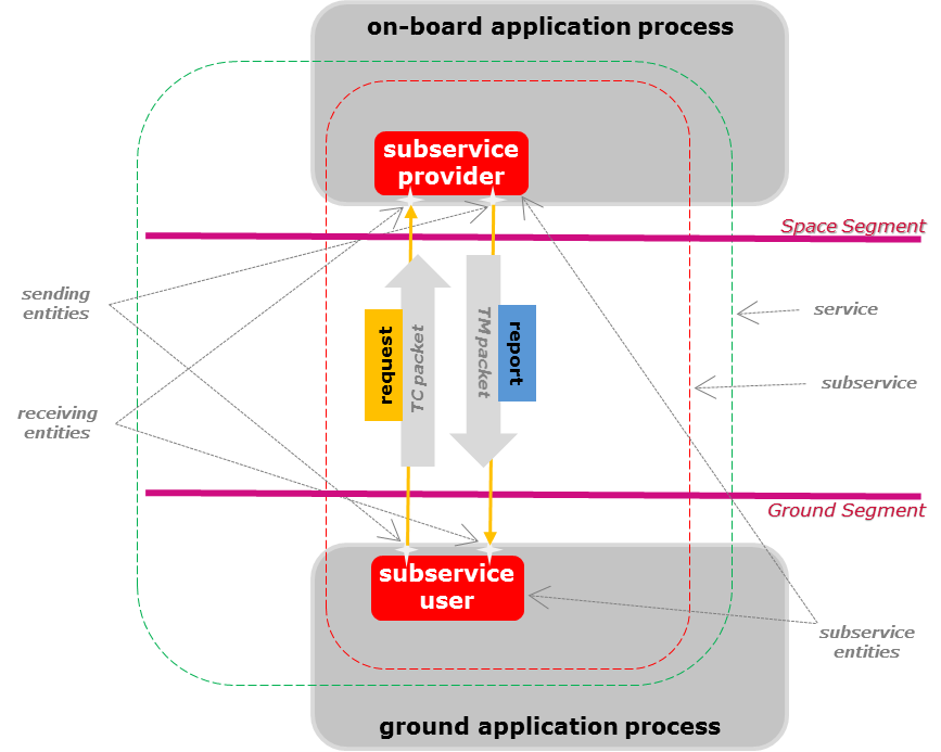
Figure 41 The space to ground PUS service system contextThe information exchanged between a subservice user and subservice provider is termed a "message". A message is transmitted semantically unchanged by the transmission protocol that connects the subservice users and subservice providers.
A message sent by a subservice user to a subservice provider, to invoke the execution of on-board activities, is termed a "request". Each request contains one or more instructions, one for each activity to execute. A message sent by a subservice provider to a subservice user is termed a "report". Each report contains one or more notifications.
Three distinct categories of report are distinguished:
the verification reports, which report on the routing, acceptance, start, progress and completion of the request execution;
the data reports, which are generated:
on request, as one or multiple responses to the instructions of a request to elicit some specific service data,
autonomously as one or multiple reports activated by a request or, routinely, i.e. as part of a continuous reporting functionality;
the event reports, which carry information related to the occurrences of the events detected by a service.
The request carries information used by the subservice provider to identify the subservice user that issued that request. This is especially interesting if several subservice users can send requests to a given subservice provider. It provides the means to the subservice provider to route the related verification reports and on-request data reports back to the subservice user who invoked the activity.
The routing of the autonomous data reports and of the event reports is either known implicitly (by design) or explicitly (e.g. by using an on-board routing table).
When messages (requests and reports) are exchanged between ground and space, they are encapsulated into CCSDS space packets, refer to clause 7.4.
Figure 42 provides an example of how PUS services can be deployed on-ground and on-board a spacecraft and how commanding with this Standard is understood.
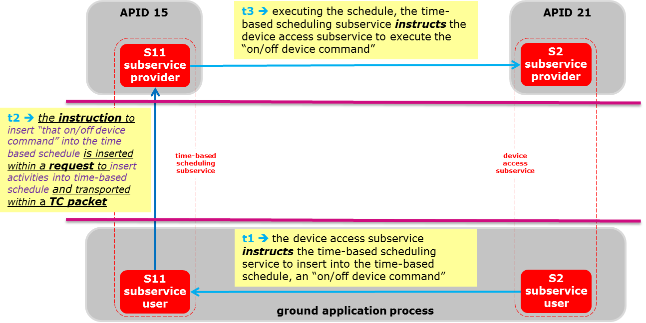
Figure 42 A PUS utilization exampleThe mechanisms which on-board application processes use to communicate with each other and with other on-board entities are implementation-dependent. Historically, spacecraft on-board interfaces have been specified and implemented on a project-by-project basis and any reuse of interfaces has usually been a by-product of reuse of existing spacecraft busses. While it is true that there are a limited number of physical interfaces available for use on-board a spacecraft, the services and access to these interfaces vary considerably between implementations. This Standard does not specify how requests, instructions, reports and notifications are implemented on-board or on-ground. It also does not specify who is in charge of encoding and decoding the telemetry and the telecommand packets.
Modelling the PUS
General
The overall PUS concept addressed in this Standard adopts a multi-layer modelling approach. The resulting model formalises the foundations of the PUS entities, in terms of system and interface requirements, together with their instantiation in space and on ground. Requirements can be applied as is or tailored for mission specific needs.
The multi-layer model, depicted in Figure 43 consists of:
the PUS foundation model,
the standard service type model,
the mission-specific service type model, and
the space system service model.
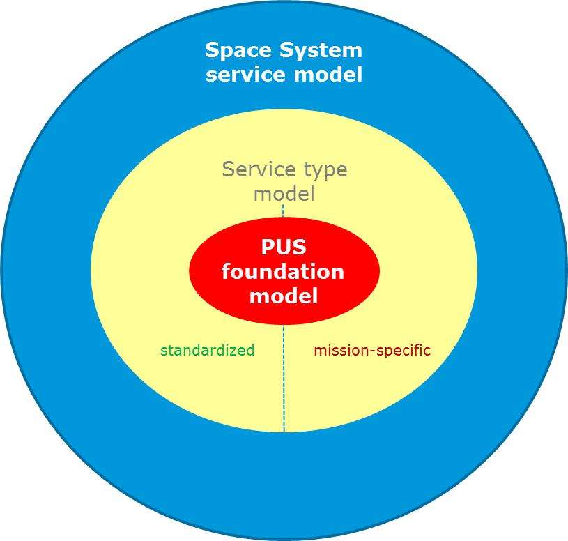
Figure 43 The PUS modelCentral to the modelling approach is the concept of a service type, which is a container for all requirements related to an interaction between space, and ground capability dedicated to the fulfilment a service objective.
The system requirements, specified in clause 6, define the semantics of each service type including:
the service type concept and related architecture;
the message type concept and related architecture;
the overall service type topology, focusing on the message exchange between the subservice users and the subservice providers.
The interface requirements define the layout and the format (i.e. the syntax) of the interaction protocol used between ground and space service entities. The interface requirements in clauses 7 and 8, specify:
how requests are transported within PUS telecommand packets compliant with the CCSDS Space Packet Protocol;
how reports are transported within PUS telemetry packets compliant with the CCSDS Space Packet Protocol.
The PUS foundation model
The PUS foundation model defines the PUS generic concepts, related terms and definitions and the business rules that:
have been used by the authors of this Standard for producing the Standard service type model,
apply to each mission that applies this Standard and define a level of tailoring of the service type model, and
apply to the architects of the mission-specific space system (i.e. both the space segment and the ground segment) who develop and instantiate the tailored service type model for the mission.
The PUS foundation model addresses a generic and abstract definition of the PUS service type model that applies to each service type whether it is standardized or mission-specific.
The PUS foundation model contains the generic rules that apply to each mission that tailors this Standard:
when creating mission-specific subservice types within a standardized service type;
when adding mission-specific service type capabilities and related message types to standardized service types and subservice types;
when creating mission-specific service types with associated subservice types, service type capabilities and related message types.
The PUS foundation model also contains the generic rules that apply to each implementation of a service type.
The PUS foundation model is specified in clause 5.
The service type model
Introduction
The PUS service type model includes:
the standardized service types as specified in this Standard, and
mission-specific extensions in terms of:
add-ons to the standard service types,
mission-specific service types.
Standard service types
This Standard contains the specification of a set of standard PUS service types. The choice of which service types are used by a new mission depends on the mission requirements. All service types are optional and a given service type can be implemented at any of several distinct levels and its parameters and functions can be tailored.
The standard service types are listed in Table 41. They include:
service types that provide basic functions such as collecting parameter statistics.
service types that hold requests and release them to another service as appropriate. The time-based scheduling, the position-based scheduling and the event-action service types are examples of service types that hold and release requests following the occurrences of specified events.
service types that provide standardized interfaces, for example to on-board devices, to an OBCP (on-board control procedure) engine or to an on-board file handling system.
The requirements specification of each of the standard service types consists of two parts:
a system requirements specification contained in clause 6 that defines the actions of the service, including its behaviour when it receives a request. The system specification is concerned with the semantics of the requests and reports.
an interface requirements specification contained in clause 8 that defines the syntax of the requests and reports for a service type. The fields in a request or report are defined using the standard PUS field types specified in clause 7.3.
Table 41: The standardized service types
|
service type
| |
|
name
|
ID
|
|
request verification
|
1
|
|
device access
|
2
|
|
housekeeping
|
3
|
|
parameter statistics reporting
|
4
|
|
event reporting
|
5
|
|
memory management
|
6
|
|
(reserved)
|
7
|
|
function management
|
8
|
|
time management
|
9
|
|
(reserved)
|
10
|
|
time-based scheduling
|
11
|
|
on-board monitoring
|
12
|
|
large packet transfer
|
13
|
|
real-time forwarding control
|
14
|
|
on-board storage and retrieval
|
15
|
|
(reserved)
|
16
|
|
test
|
17
|
|
on-board control procedure
|
18
|
|
event-action
|
19
|
|
parameter management
|
20
|
|
request sequencing
|
21
|
|
position-based scheduling
|
22
|
|
file management
|
23
|
|
Note: The reserved service type identifiers were used in previous versions of this Standard. This Standard no longer promotes the use of these service types but does not preclude that existing implementations are reused for new missions.
| |
Mission-specific service types
When applying the PUS Standard, a mission instantiates this Standard by tailoring it for their needs. That instantiation results in a mission-specific packet utilization definition document that is rendered applicable to all partners involved in that mission.
The mission-specific packet utilization definition document contains the mission-specific service type model that includes:
all PUS standardized service types considered suitable for use by that mission, each one tailored according to the mission needs,
all mission-specific additional service types.
The space system service model
The space system service model results from the deployment of the service type model for a given mission, i.e. resulting from the space system architecture of that mission.
The space system service model contains the service topology in terms of:
the instances of the service types and related hosting application processes, and
for each instance, its full specification resulting from the tailoring of the related service type.
Deploying the space system service model implies for each on-board application process, selecting the services and related subservice providers to be hosted by that application process. This Standard specifies the following interdependencies between services:
the request verification service is accessible to any other service within the same application process;
the event reporting service and the large packet transfer service are accessible to any other service;
the on-board monitoring service and the event-action service require the presence of an event reporting service;
if an on-board control procedure service supports the capability for configuring the OBCP execution observability level, then that service requires the presence of an event-reporting service, refer to clause 6.18.4.8.
The PUS foundation model
Introduction
The PUS foundation model specifies a generic service and service type model in the form of a set of generic concepts with the associated business rules. The PUS foundation model provides rules that are applicable to any service type, i.e. standardized or mission-specific and any of their instances (i.e. the services).
As any service type definition relies on the PUS foundation model, the architectural consistency of each service type is ensured.
The PUS foundation model defines generic concepts and associated requirements related to two levels of abstractions, i.e.:
The generic service type abstraction level, which specifies the set of generic object types and business rules that are required for ensuring the overall consistency of the service type model. This abstraction level includes all generic object types used to produce, by specialization, the standardized and the mission specific service types.
The generic service deployment abstraction level, which specifies the set of generic object types and business rules that are required to capture the space system service model. This abstraction level includes all generic object types used to capture, by instantiation, the space system services resulting from the space system overall architecture.
The generic service type abstraction level specifies:
the service type, the subservice type and the capability type;
the subservice provider, the subservice user;
the message type, i.e.:
the request type and the instruction type,
the report type and the notification type;
the transaction type and its type-dependent definitions, i.e.:
for a request related transaction:
the request type,
the associated execution notification type, and
if some service data are generated in response to such a request, the related data report type;
for an autonomous data reporting transaction, the data report type;
for an event reporting transaction, the event report type.
The generic service deployment abstraction level specifies:
the system context of the service, in terms of the involved system objects of relevance to the service functionality, e.g. the space segment, the ground segment, the application process, the on-board parameter, the on-board memory;
the service, the subservice and the capability exposed by the subservice;
the message, i.e.:
the request, the instruction slot and the instruction,
the report, the notification slot and the notification;
the transaction.
Convention
This Standard uses two types of identification mechanisms:
names for human communication, and
identifiers for communicating with the spacecraft.
Names and identifiers are always unique in a given context.
The wider context that is considered by this Standard is the (single) spacecraft. This means that, for this Standard, when a name or an identifier is declared as unique within a given context, that context is implicitly understood as a context within the spacecraft.
The generic service type abstraction level
General
Each service type shall be uniquely identified by exactly one service type name.
Each service type shall be uniquely identified by exactly one service type identifier that is an unsigned integer greater than or equal to 1, and less than or equal to 255.
The service type identifiers are used in the telemetry packet secondary header (refer to clause 7.4.3.1) and in the telecommand packet secondary header (refer to clause 7.4.4.1), together with a message subtype identifier to uniquely identify a message type.
Each standard service type shall have a service type identifier less than or equal to 127.
The standard service types are specified in the different versions of this Standard. When mission specific functionalities, identified by a mission specific service type, are considered adequate for being standardized, a new standard service type is created. When a standard service type is no longer considered adequate for remaining a standard, that service type is removed from the Standard; its service type identifier is not reused.
Each mission specific service type shall be associated with a service type identifier greater than or equal to 128.
Subservice type
Each service type shall define at least one subservice type.
This Standard introduces the concept of subservices that group and isolate the functions of a service.
Each subservice type shall be defined by exactly one service type.
Each subservice type shall be uniquely identified by exactly one subservice type name.
For each subservice type, whether the realization of that subservice type is implicitly required for each realization of the service type or required by tailoring shall be declared when specifying that subservice type.
- An example of a subservice type that is implicitly required is the "parameter monitoring" subservice type. Each realization of the "on-board monitoring" service type is implicitly required to include a realization of that subservice type, refer to requirement 6.12.2.1.1a and clause 6.12.3.
- An example of a subservice type that is required by tailoring is the "functional monitoring subservice", refer to requirement 6.12.2.1.2a and clause 6.12.4.
For each subservice type, whether multiple realizations of that subservice type are allowed within a single service shall be declared when specifying that subservice type.
An example of a subservice type where multiple realizations are allowed within a single service is the "packet selection" subservice type, refer to requirement 6.15.2.1.2a and clause 6.15.4.
For each subservice type, the observables shall be declared when specifying that subservice type.
These observables are on-board parameters that are provided by the related subservice, refer for example to the observables of the parameter monitoring subservice in clause 6.12.3.13.
Message type
General
Each message type shall be uniquely identified by exactly one message type name.
Each message type shall be uniquely identified by exactly one message type identifier.
These identifiers are used in the telemetry packet secondary header (refer to clause 7.4.3.1) and in the telecommand packet secondary header (refer to clause 7.4.4.1) to identify the type of messages transported by these packets but also in specific requests and reports, e.g. in the requests to add report types to the application process forwarding control table (refer to clause 6.14.3.4.1).
Each message type identifier shall be composed of:
- the service type identifier of the service type that contains that message type;
- a message subtype identifier that uniquely identifies that message type within that service type.
Each message subtype identifier shall be an unsigned integer greater than or equal to 1, and less than or equal to 255.
Each standard message type identifier shall have a message subtype identifier less than or equal to 127.
The standard message type identifiers are the identifiers specified in this Standard.
Each mission specific message type that belongs to a standard service type shall have a service subtype identifier greater than or equal to 128.
Each message type shall either be:
- a request type, or
- a report type.
- For item 1, refer to clause 5.3.5.2.
- For item 2, refer to clause 5.3.3.3.
Request type
Each request type shall define one or more instruction types.
- An example of a request type that defines exactly one instruction type is the "modify parameter monitoring definitions" request type specified in clause 6.12.3.9.4. The single related instruction type is the "modify a parameter monitoring definition" instruction type specified in requirement 6.12.3.9.4c.
- An example of a request type that defines more than one instruction type is the "report parameter monitoring definitions" request type specified in clause 6.12.3.10. The related instruction types are specified in requirement 6.12.3.10b, i.e.:
- the "report a parameter monitoring definition" instruction type,
- the "report all parameter monitoring definitions" instruction type.
- The decision to link several instruction types to the same request type instead of having a request type for each instruction type is an operational issue. For example, if an instruction type acts on one instance of a system object and another instruction type on all instances of that system object, if the operational criticality of the "one" instruction differs from the operational criticality of the "all" instruction, this Standard recommends to define two request types.
Each instruction type shall be defined for exactly one request type.
Each instruction type shall be uniquely identified by exactly one instruction type name.
For each request type and for each instruction type of that request type, whether that request type provides a single instruction slot or multiple instruction slots for that instruction type shall be declared when specifying that request type.
For some instruction types, it make sense to allow multiple instructions in a request and, for others, it does not. Although an instruction type offers the possibility to have multiple instructions of that type inside a single request, that multiple instructions capability is a decision taken at request type level.
An example of an instruction type that offers the possibility to have multiple instructions inside a single request is the "report a parameter monitoring definition" instruction type specified in requirement 6.12.3.10b for which the request to "report parameter monitoring definitions" defined in clause 6.12.3.10 provide the capability to have multiple instructions inside a single request.
An example of an instruction type for which it does not make sense to allow multiple instructions in a request is the "report all parameter monitoring definition" instruction type also specified in requirement 6.12.3.10b.
For each request type that contains several instruction types, the allowed combinations of instruction types that can be used in a request of that request type shall be declared when specifying that request type.
An allowed combination of instruction types means that the realizations of two or more of those instruction types can be merged in a single request of the corresponding request type, see for example the add report types to the application process storage-control configuration specified in clause 6.15.4.4.1.
For each instruction type, the instruction arguments used by that instruction type, their definition and their ordering within the instruction type shall be declared when specifying that instruction type.
For each request type that provides multiple instruction slots, if that request type constrains the scope of the instructions that can be issued within a request of that type, the argument or set of arguments of the related instruction types that define that scope shall be grouped together in the definition of the request type.
This requirement avoids constructing and issuing a request with multiple times the same instruction argument value or set of argument values. For example, the request type to time-shift scheduled activities identified by request identifier has a time-offset argument that precedes the instruction slots. That time offset applies to each instruction in the request (as specified in clause 6.11.9.3).
For each request type, the definition of the request arguments provided by that request type, their definition and their ordering within the request type shall be declared when specifying that request type.
A request type argument can be an instruction type argument (or set of instruction type arguments) as specified in requirement 5.3.3.2g, or a directive argument (or set of directive arguments) specifying, for example,
- an on-board condition to allow executing the instructions of the requests of that type,
- a mode to set (e.g. the configuration execution flag of the request to apply parameter functional reporting configurations, refer to clause 6.3.5.3).
Report type
Each report type shall either be:
- a data report type,
- a verification report type, or
- an event report type.
- For item 1, an example of a data report type is the housekeeping parameter report type specified in clause 6.3.3.3.
- For item 2:
- the verification report types are those specified in clause 6.1, i.e. the request verification service type.
- the verification reports are used in the request related transactions, refer to clause 5.3.5.2.
- For item 3, the event report types are those specified in clause 6.5.4, see also clause 5.3.5.4.
Each report type shall define exactly one notification type.
If a report type is associated to a request related transaction type (i.e. that report type is a response type) and associated to an autonomous data reporting transaction type (i.e. that report type is also an autonomous data report type), the same notification type is used for both transaction types.
Each notification type shall be defined for exactly one report type.
Each notification type shall be uniquely identified by exactly one notification type name.
For each report type and for each notification type of that report type, whether that report type provides a single notification slot or multiple notification slots for that notification type shall be declared when specifying that report type.
For some notification types, it makes sense to allow multiple notifications in a report. For others, it does not. Although a notification type offers the possibility to have multiple notifications of that type inside a single report, that multiple notifications capability is a decision taken at report type level.
An example of a notification type that offers the possibility to have multiple notifications inside a single report but for which it is explicitly required to have only one notification per report is the housekeeping parameter report structure report specified in clause 6.3.3.6.
Capability type
Each subservice type shall define at least one capability type.
Each capability type defines one or more interrelated functions of the subservice type. A capability type can represent:
- a single function, e.g. for "the capability to distribute on/off device commands" specified in clause 6.2.4.2;
- a set of two or more exclusive-or related functions, e.g. for the exclusive-or constraint to use either the CUC format or the CSD format (but not both) when reporting the on-board time, refer to requirement 6.9.4.1a;
- a set of two or more inclusive-or related functions, e.g. for the inclusive-or constraint to provide at least one means to load OBCPs, refer to requirement 6.18.4.4.1a;
- a set of interrelated functions, e.g. for the capability to enable and disable the scrubbing of a memory specified in clause 6.6.6.1.4 and 6.6.6.1.5 whereas the decision to provide the capability to enable the scrubbing of a memory implies to provide the capability to disable the scrubbing of a memory (refer to requirement 6.6.6.1.5a).
For each capability type defined by a subservice type, the applicability constraints of that capability type shall be declared when specifying that subservice type.
The applicability constraint of each standardized capability type is specified in clause 6 (see also Annex C). For example:
-
a "minimum" applicability constraint means that each related subservice provides that capability (see for example Table C-1 );
-
a "by declaration" applicability constraint means that for each related subservice, whether that capability is provided by that subservice is a decision to take when specifying that subservice (See for example requirement 6.3.3.4.1a);
-
an "implied by another capability type" applicability constraint means that if a subservice provides that other capability then that subservice also provides that implied capability (see for example requirement 6.3.3.4.2a);
-
a "by declaration and only if another capability type is provided" applicability constraint means that the decision to include that capability depends on the decision taken for that subservice to provide that other capability (see for example requirement 6.2.5.3a and the associated note).
Applicability constraints can also be defined for a set of capability types. For example: -
an exclusive-or applicability constraint means that a subservice can provide at most one of the related capabilities (see for example requirement 6.9.4.1a);
-
an inclusive-or applicability constraint means that a subservice provides at least one of the related capabilities (see for example requirement 6.2.3a).
Transaction type
General
Each transaction type shall be defined by exactly one capability type.
Each transaction type shall either be:
- a request related transaction type,
- an autonomous data reporting transaction type, or
- an event reporting transaction type.
- For item 1, refer to clause 5.3.5.2.
- For item 2, refer to clause 5.3.5.3.
- For item 3, refer to clause 5.3.5.4.
Request related transaction type
General
Each request related transaction type shall involve exactly one request type.
The verification report types introduced in clause 5.3.3.3 are involved in the request related transaction types as a consequence of the execution verification profile specified in clause 5.3.5.2.3.
Each request type shall be involved in exactly one request related transaction type.
Response type
Each request type shall be linked to at most one data report type.
- An example of a request type that is linked to a data report type is the "report parameter monitoring definitions" request type. The linked data report type, playing the role of the response type, is the "parameter monitoring definition report", refer to requirement 6.12.3.10a.
- As stated in requirement 5.3.3.3b, each data report type defines exactly one notification type. The link that exists between a request type and a report type implies that each instruction type defined by that request type is linked to the notification type defined by that report type.
For each instruction type that is linked to a notification type, whether a realization of that instruction type can cause the generation of multiple notifications shall be declared when specifying that instruction type. - An example of an instruction type whose realization can cause the generation of multiple notifications is the "report all parameter monitoring definitions" instruction type, refer to requirement 6.12.3.10h.
- An example of an instruction type whose realization causes the generation of a single notification is the "report a parameter monitoring definition" instruction type, refer to requirement 6.12.3.10g.
Execution verification profile
For each request type, the pre-conditions to verify prior to starting the execution of each request of that type shall be declared when specifying that request type.
- An example of such a request-type-specific pre-conditions is the existence of the parameter functional reporting definition indicated by the argument of the "add parameter report definitions to a parameter functional reporting definition" request type, refer to requirement 6.3.5.6.1c.1.
- This Standard does not list the checks to perform to avoid the execution of a request that has no effect if the absence of such check causes no operational ambiguity. It is for the mission to decide if and where to perform the checks, i.e. on-board or on-ground
For each instruction type, the pre-conditions to verify prior to starting the execution of each instruction of that type shall be declared when specifying that instruction type.
An example of such instruction-specific pre-conditions is the existence within the parameter functional reporting definition of the parameter report definition indicated by the instruction-specific argument of the instruction to "add a parameter report definition to a parameter functional reporting definition", refer to requirement 6.3.5.6.1f.1.
For each request type that provides a multiple instruction slots capability, whether the subservice verifies the suitability of all instructions contained within each request of that type before authorizing the start of execution of that request shall be declared when specifying that request type.
- This Standard applies the operational concept that verifying on-board the suitability of all instructions before authorizing the start of execution of a request implies the failure of that start of execution if not all instructions are suitable for execution.
- An example of a request type whose realizations can only be executed if all their instructions are suitable for execution is the request to "load raw memory data areas", refer to requirement 6.6.3.3.2e.
- An example of a request type whose realizations can be executed without ensuring that all their instructions are suitable for execution is the request to "enable parameter monitoring definitions", refer to requirement 6.12.3.6.2d. The instructions contained within such a request are by nature independent.
For each instruction type, the conditions to verify during the execution of each instruction of that type shall be declared when specifying that instruction type.
For each instruction type, the post-conditions to verify at the end of the execution of each instruction of that type shall be declared when specifying that instruction type.
For each request type, the post-conditions to verify at the end of the execution of each request of that type shall be declared when specifying that request type.
For each request type, the execution verification profile used to report the start, progress and completion of execution of each request of that type shall be declared when specifying that request type.
The execution verification profile can include any of the following:
- for each request-specific successful start of execution condition to notify, a code value that refers to that condition;
- for each request-specific failed start of execution condition to notify, a failure notice made of a code value that refers to that condition together with any number of associated parameters whose values are reported to support the processing of that failed execution notification;
- for each instruction-specific successful start of execution condition to notify, a code value that refers to that condition;
- for each instruction-specific failed start of execution condition to notify, a failure notice made of a code value that refers to that condition together with any number of associated parameters whose values are reported to support the processing of that failed execution notification;
- for each instruction-specific successful progress of execution condition to notify, a code value that refers to that condition;
- for each instruction-specific failed progress of execution condition to notify, a failure notice made of a code value that refers to that condition together with any number of associated parameters whose values are reported to support the processing of that failed execution notification;
- for each instruction-specific successful completion of execution condition to notify, a code value that refers to that condition;
- for each instruction-specific failed completion of execution condition to notify, a failure notice made of a code value that refers to that condition together with any number of associated parameters whose values are reported to support the processing of that failed execution notification;
- for each request-specific successful completion of execution condition to notify, a code value that refers to that condition;
- for each request-specific failed completion of execution condition to notify, a failure notice made of a code value that refers to that condition together with any number of associated parameters whose values are reported to support the processing of that failed execution notification.
Each progress of execution notification shall provide the means to uniquely identify the instruction that progress of execution is notified.
This identification is used by the subservice user that has initiated the execution of that instruction.
For each instruction type, the functionality that the subservice performs when executing an instruction of that type shall be declared when specifying that instruction type.
An example of such subservice functionality can be found in 6.3.5.6.1i.
For each request type, the request-specific functionality that the subservice performs when executing a request of that type shall be declared when specifying that request type.
Autonomous data reporting transaction type
Each autonomous data reporting transaction type shall involve exactly one data report type.
- Examples of autonomous data report types are:
- the housekeeping parameter report type (refer to clause 6.3.3.3),
- the diagnostic parameter report type (refer to clause 6.3.4.3),
- the check transition report type (refer to clause 6.12.3.7).
- It is noted that some data reports can be generated autonomously but also in response to specific requests. This is for example the case of the housekeeping parameter reports that can be generated periodically according to a collection interval (refer to requirement 6.3.3.2c), but are also generated as the response of a request to generate a one shot report for housekeeping parameter report structures (refer to clause 6.3.3.7).
Each data report type shall be involved in at most one autonomous data reporting transaction type.
Event reporting transaction type
Each event reporting transaction type shall involve exactly one event report type.
This Standard defines four types of event reports according to the severity level of their associated events:
- the informative event report type,
- the low severity event report type,
- the medium severity event report type, and
- the high severity event report type.
The message subtype identifier gives the severity level of the event report types, refer to clause 6.5.4. For example, all event reports for low severity events have the same message type. i.e. the same combination of service type identifier and message subtype identifier. There is no means, at event report type level, to identify the event that is associated to the related event reports. For that event association, this Standard defines the concept of event definitions. Each event definition is associated to a single event and a single event report type. Each event definition is uniquely identified by the combination of the application process that generates the corresponding event reports and an event definition identifier that is unique within the context of that application process (refer to clause 6.5.3).
Each event report type shall be involved in exactly one event reporting transaction type.
Tailoring the generic service type abstraction level
Tailoring the generic service type abstraction level shall consist of:
- adding mission-specific service types;
- adding mission-specific subservice types;
- adding mission-specific capability types;
- adding mission-specific message types.
Reducing the standardized functional capabilities offered by the generic service type abstraction level (i.e. clause 5.3) is not recommended since it can negatively affect the reuse of existing elements (hardware or software).
The generic service deployment abstraction level
Introduction
The services are functional entities that involve both ground elements and on-board elements.
A service is composed of one or more subservices. Each subservice involves:
one or more subservice users, each one hosted by an application process that resides on-ground or on-board, and
exactly one subservice provider that is usually hosted by an on-board application process.
The communication between the subservice entities (i.e. a subservice user and a subservice provider) consists of exchanging messages between these entities. When messages are exchanged between the ground segment and the space segment, these messages are transported in CCSDS packets as specified in clause 7.
Application process
General
Each application process shall either be:
- an on-board application process, or
- a ground application process. Each application process that hosts at least one subservice provider shall be identified by an application process identifier that is unique across the system that hosts that subservice provider.
- This Standard acknowledges that the same application process identifier can be used to identify several application processes. This is for example the case during the space system development where different representations of a given application process are used, e.g. a simulated version of an application process used for testing the ground segment but also during operations, e.g. in case of cold redundancy.
- The system introduced in this requirement can be, for example, the spacecraft that hosts the on-board application process. The concept of system identifier is also used in this Standard to uniquely identify that system across the overall space system. This Standard does not further elaborate on this system concept and its identifier.
Each application process identifier shall be an unsigned integer that is less than or equal to 2046. - This application process identifier is used to identify the on-board application process that is the destination for a request and the source for a report.
- The APID 2047 is reserved for idle packets. The APID 0 is reserved for spacecraft time packets. Other APID values are reserved, refer to the space assigned numbers authority registry (see bibliography).
Each application process that hosts at least one subservice user shall be identified by an application process user identifier that is unique within the context of the overall space system. - The subservice users are in charge of issuing requests and processing reports. As such, an application process that can only receive reports also has an application process user identifier.
- The application process user identifier is used:
- as "source identifier" for any request generated by that application process (see also the source ID field of the telecommand packet secondary header specified in requirement 7.4.4.1b), and
- as "destination identifier" for any report whose final destination is that application process (see also the destination ID field of the telemetry packet secondary header specified in requirement 7.4.3.1b).
- This Standard acknowledges that the same application process user identifier can be used to identify several application processes, e.g. in case of cold redundancy.
Each application process user identifier shall be an unsigned integer that is greater than or equal to 0, and less than or equal to 65535.
For each report that it generates, each on-board application process shall time tag that report using the on-board reference time.
For each application process, whether that application process time tags the reports before collecting the values of the constituting parameters or after shall be declared when specifying that application process.
When a report contains parameter values acquired at different times (e.g. housekeeping reports with multiple samples of the same parameter), the acquisition time of each set of parameter values can be deduced from the time tag of the report.
For each application process, whether that application process provides the capability to report the status of the on-board time reference used when time tagging reports shall be declared when specifying that application process.
For each application process, whether that application process provides the capability to count the type of generated messages per destination and report the corresponding message type counter shall be declared when specifying that application process.
Each application process that provides the capability to count the type of generated messages per destination and report the corresponding message type counter shall maintain, per destination, a counter for each message type that it generates.
Interfaced system objects
Introduction
Each service interacts with objects of the overall space system. These system objects are either:
defined within the scope of a service, or
defined externally, e.g. an on-board memory that is defined at spacecraft level and used by several services.
The system objects that are defined within the scope of a service are maintained by that service and their visibility is often limited to that service. They expose properties that are used by the service to perform its functionality.
The system objects that are externally defined have their own existence independently of any service. They expose properties that are accessed by some services for the purpose of e.g. performing the service functionality, monitoring and controlling those system objects.
The system objects introduced in this Standard are:
the on-board parameters, refer to clause 5.4.3.2;
the on-board memories, refer to clause 5.4.3.3;
the virtual channels, refer to clause 5.4.3.4;
the on-off devices, refer to clause 6.2.4;
the registries, refer to clause 6.2.5;
the CPDUs, refer to clause 6.2.6 and clause 9;
the physical and the logical devices, refer to clause 6.2.7.1.1 and clause 6.2.7.2.1;
the housekeeping parameter report structures, refer to clause 6.3.3.2;
the diagnostic parameter report structures, refer to clause 6.3.4.2;
the parameter functional reporting definitions, refer to clause 6.3.5.2;
the event definitions, refer to clause 6.5.3;
the functions, refer to clause 6.8.3.1;
the time-based sub-schedules, refer to clause 6.11.5.1;
the time-based scheduling groups, refer to clause 6.11.6.1;
the parameter monitoring definitions, refer to clause 6.12.3.3;
the functional monitoring definitions, refer to clause 6.12.4.2;
the packet stores, refer to clause 6.15.3.1;
the on-board control procedures, refer to clause 6.18.4.1;
the request sequences, refer to clause 6.21.4;
the position-based sub-schedules, refer to clause 6.22.7.1;
the position-based scheduling groups, refer to clause 6.22.8.1;
the on-board file systems, refer to clause 5.4.5.
On-board parameter
Each on-board parameter shall be identified by exactly one on-board parameter identifier that is unique across the entire spacecraft.
- An on-board parameter represents e.g. a measurement taken from an on-board sensor or a software parameter held in memory.
- A service may need to acquire a reading of an on-board parameter for the purposes of its routine activity (for example, to monitor its value, to use its value to determine the validity of another on-board parameter, to use its value in a calculation etc.).
- The "baseline" set of on-board parameters is defined during the spacecraft design process. However, the flexibility can also exist to define new parameters in orbit or to change the definition of an existing on-board parameter or to set the value of an on-board parameter (refer to clause 6.20). This capability is of course restricted to software parameters held in on-board memory and the on-board software design can additionally have built-in protections to ensure against the overwriting of essential on-board parameters.
The set of on-board parameter minimum sampling intervals used to access the on-board parameters shall be declared when specifying the spacecraft architecture.
This Standard foresees that different spacecraft subsystems may use different on-board parameter minimum sampling intervals, e.g. the platform uses a parameter minimum sampling interval of 125 ms but the payload uses an interval of 500 ms.
Each on-board parameter shall be associated to exactly one on-board parameter minimum sampling interval.
- This on-board parameter minimum sampling interval is used as the unit for expressing time intervals used by the subservices that access the on-board parameters, for example, the housekeeping or monitoring services. refer also to requirement 6.12.3.3f.
- This requirement does not imply that for each on-board parameter, one can associate an on-board parameter minimum sampling interval but that such an interval is associated to a group of parameters, e.g. all parameters of a platform, all parameters of a payload.
All on-board parameters accessed by an application process shall be associated to the same on-board parameter minimum sampling interval.
On-board memory
General
Each on-board memory shall be identified by exactly one on-board memory identifier.
- The on-board memory concept introduced in this Standard is for logical memories, i.e. any logical memory space, potentially managed by different on-board processors. The mapping with physical memories is out of the scope of this Standard.
- Each physical memory is associated to a memory smallest addressable unit that specifies the minimum number of bytes that can be addressed. Each logical memory, identified by the memory identifier, is associated to a memory access alignment constraint that specifies the minimum number of bytes used by the services to address the corresponding physical memory.
- This Standard does not preclude that the same memory identifier is used by several on-board memories provided that they cannot be accessed at the same time, e.g. in the case of memory cold redundancy.
- Access to a given memory can be by either absolute addressing or relative addressing. For relative addressing, a base address (either an explicit address or a symbolic address, such as a table name) and an offset from this base address are specified.
At any time, each on-board memory identifier shall uniquely identify exactly one on-board memory that is unique across the entire spacecraft.
For each on-board memory, the following characteristics of that memory shall be declared when specifying that memory: - the memory access alignment constraint;
- the memory size, in bytes;
- the allowed operations;
- the addressing scheme.
For item 4, refer to clause 5.4.3.3.2.
When declaring the characteristics of an on-board memory, the allowed operations shall be one of the following:
- "read only";
- "read and write";
- "write only".
For each on-board memory, whether scrubbing that memory is supported shall be declared when specifying that memory.
For each on-board memory, whether write protecting that memory is supported shall be declared when specifying that memory.
Addressing scheme
For each on-board memory, whether an absolute addressing scheme for that memory is exposed in the space to ground interface shall be declared when specifying that memory.
Absolute addressing implies that the memory addresses and related offsets shall be expressed in bytes.
For each on-board memory, whether a base plus offset addressing scheme for that memory is exposed in the space to ground interface shall be declared when specifying that memory.
Base plus offset addressing means that the memory addresses are byte offsets from a base reference. A base reference gives (explicitly or implicitly) the address within the memory which is used as the byte-zero reference for the offset. The base reference can itself be an absolute address or a symbolic address e.g. the name of a table, a parameter set or a file whose absolute address is implicitly known on-board.
Base plus offset addressing implies that the base references when expressed as an absolute address and related offsets shall be expressed in bytes.
Base plus offset addressing implies that the byte offsets are offsets from the first byte of the referenced area within the object referenced by the base independently of the actual physical storage within the memory used to store the related data.
Virtual channel
The list of virtual channels defined for downlinking reports and their characteristics shall be declared when specifying the space to ground interface.
For the virtual channel, refer to ECSS-E-ST-50-03. See also clause 7.1.2.2.
For each virtual channel defined for downlinking reports, the virtual channel identifier used to refer to that virtual channel shall be declared when specifying that virtual channel.
Checksum algorithm
For each checksum algorithm used on-board, the list of subservice providers that use that checksum algorithm shall be declared when specifying the spacecraft architecture.
- This requirement is justified by the system need to ensure that all subservice providers that provide means to checksum a specific data object use the same checksum algorithm. For example, if a file contains an OBCP that can be checksummed by the OBCP service and that file is also managed by a memory service, the same checksum algorithm is used by both services.
- The checksum algorithm implies the type of checksum i.e. ISO or CRC, and the size of the checksum.
- The checksum algorithm to use to checksum all telemetry packets and the checksum algorithm to use for all telecommand packets are specified in requirements 7.4.3.2e and 7.4.4.2d.
On-board file system
Each on-board file system shall be identified by exactly one on-board file system identifier that is unique across the entire spacecraft.
For the on-board file system, refer also to clause 6.23.
Each object in an on-board file system shall be uniquely identified by an object path that is the combination of a repository path and an object name.
The term object refers to a file or to a directory.
For each on-board file system, whether that file system supports files with unbounded size shall be declared when specifying that file system.
A file of unbounded size means that the file is only limited by the actual available physical memory size.
The set of file attributes supported by each on-board file system shall be declared when specifying that file system.
For example, the file type, its creation date.
For each on-board file system, whether that file system provides the capability to lock files shall be declared when specifying file system.
An on-board file system shall not be accessed by more than one file management service.
Service
Each service shall be of exactly one service type.
For each subservice type whose realization is implicitly required, each service of the related service type shall provide at least one subservice of that subservice type.
An example of a subservice type whose realization is implicitly required is the parameter monitoring subservice type of the on-board monitoring service type, refer to requirement 6.12.2.1.1a.
For each subservice type whose realization is required by tailoring and for each service of the service type that defines that subservice type, whether the realization of that subservice type is required for that service shall be declared when specifying that service.
An example of a subservice type whose realization is required by tailoring is the functional monitoring subservice type of the on-board monitoring service type, refer to requirement 6.12.2.1.2a.
For each subservice type that allows multiple realizations within a single service, each realization of that subservice type shall be declared when specifying that service.
An example of a subservice type that allows multiple realizations within a single service is the packet selection subservice type of the on-board storage and retrieval service type, refer to requirement 6.15.2.1.2a.
The service topology of the overall space system shall be declared when specifying the space system architecture.
The service topology includes:
- the list of subservices provided by each service,
- the on-board service topology, i.e. for each service, the subservice provider of each related subservice and the on-board subservice users, if any, of each subservice, and
- the ground service topology, i.e. for each service, the subservice users of each related subservice.
Subservice
General
Each subservice shall be of exactly one subservice type.
Each subservice shall belong to exactly one service.
The type of a subservice is one of the subservice types defined for the related service type.
Subservice entity
General
Each subservice entity shall belong to exactly one subservice.
Each subservice entity shall be hosted by exactly one application process.
Each subservice entity shall be either a subservice user or a subservice provider.
A subservice entity is identified by the subservice that it belongs to and the application process that hosts it.
Subservice provider
Each subservice shall provide exactly one subservice provider.
A subservice provider is an operational element of a subservice that is in charge of execution of the subservice requests and generation of the subservice reports. The subservice providers are usually hosted by the on-board application processes.
Subservice user
Each subservice shall provide at least one subservice user.
A subservice user is an operational element of a subservice that is in charge of initiating the subservice requests and processing the subservice reports. The subservice users are either hosted by the ground application processes or the on-board application processes.
Capability
Each subservice shall provide at least one subservice capability.
For each subservice and for each capability type defined by the corresponding subservice type, the inclusion of the related capability in that subservice shall comply with the applicability constraints of that capability type.
For the applicability constraints of a capability type, refer to requirement 5.3.4b.
Failed progress of execution
For each request type for which a failed progress of execution can be reported, whether the corresponding failed progress of execution notifications are reported within failed progress of execution verification reports or as part of the completion of execution verification report for the related requests shall be declared when specifying the request type related subservice.
This requirement also applies to the standardized request types specified in clause 6 that do not specify the related failed progress of execution notifications reporting policy.
Transaction
Each subservice shall provide the means to manage all transactions that it initiates according to the mission operational requirements.
A transaction is either:
- a request related transaction,
- an autonomous data reporting transaction, or
- an event reporting transaction.
Each transaction shall be initiated and maintained by exactly one subservice.
Each transaction involves one or more messages exchanged between a subservice user and a subservice provider.
A request related transaction involves:
- a request,
- depending on the acknowledgement specified for that request (refer to clause 5.4.11.2.2) and the execution verifications of that request (refer to clause 5.4.11.2.3), zero or more verification reports,
- depending on the successful execution of the instructions contained within that request, if that request type is linked to a response type, one or more responses (refer to clause 5.3.5.2).
An autonomous data reporting transaction involves an autonomous data report.
An event reporting transaction involves an event report.
Message
General
Each message shall be of a single message type.
The message type is specified in clause 5.3.3. A message is either a request or a report.
Request
General
Each request shall be generated by exactly one subservice user.
- By convention, a request is said to be generated by the application process that hosts the subservice user that generates that request.
- If the application process that generates the request is a ground application process, by convention, the request is also said to be generated by
- the monitoring and control system that hosts that application process,
- the ground segment.
Each request shall be addressed to exactly one subservice provider.
Each request shall be uniquely identified by a request identifier that is the combination of: - a source identifier that corresponds to the application process user identifier of the application process that hosts the subservice user that generates that request;
- a destination identifier that corresponds to the combination of the application process identifier of the application process that hosts the subservice provider that is responsible for executing that request and the system identifier of the system that hosts that application process;
- a sequence count or request name that is produced by the application process that hosts the subservice user.
- This Standard assumes that the request identifier is unique for the mission duration but does not further elaborate on how this uniqueness is achieved. In reality, it can happen that the same identifier is used for several requests, e.g. during tests or when the sequence count counter wraps around, implying the need to include timing information to ensure the uniqueness of request identification for the overall mission duration.
- For item 1, refer to requirement 5.4.2.1d.
- For item 2, refer to requirement 5.4.2.1b.
- When a request is transported within a CCSDS telecommand packet, refer to clause 7.4:
- the application process identifier of the destination identifier is set in the application process identifier field of the packet identification field of the packet primary header field;
- the sequence count or request name is set in the packet sequence count or packet name field of the packet sequence control field of the packet primary header field;
- the source identifier is set in the source identifier field of the packet secondary header field.
Each request shall be of exactly one request type.
Each request whose request type provides a single instruction slot shall contain exactly one instruction that is of an instruction type defined for that request type.
Each request whose request type provides multiple instruction slots shall contain an ordered list of one or more instructions, each one being of an instruction type defined for that request type.
For example, the request to "enable event-action definitions" can include either a single instruction to "enable all event-action definitions" or one or more instructions to "enable an event-action definition", refer to requirement 6.19.7.1b.
Acknowledgement
Each request shall contain:
- a flag indicating whether the reporting of the successful acceptance of that request by the destination application process is requested;
- a flag indicating whether the reporting of the successful start of execution of that request by the destination application process is requested;
- a flag indicating whether the reporting of the successful progresses of execution of that request by the destination application process is requested;
- a flag indicating whether the reporting of the successful completion of execution of that request by the destination application process is requested.
- Related to item 1:
- each successful acceptance is only reported if that flag indicates such reporting need, refer to requirement 6.1.4.2d;
- each failed acceptance is reported by the destination application process, refer to requirement 6.1.4.3f.
- For item 2:
- each successful start of execution is only reported if the item 2 flag indicates the reporting need, refer also to requirements 5.4.11.2.3a.2 and 6.1.5.1.1b;
- each failed start of execution is notified by the subservice provider in charge of executing that request and reported by the destination application process that hosts that subservice provider, refer to requirements 5.4.11.2.3a.1 and 6.1.5.1.2b.
- For item 3:
- each successful progress of execution is only reported if the item 3 flag indicates the reporting need, refer also to requirements 5.4.11.2.3a.3(c) and 6.1.5.2.1b;
- each failed progress of execution is notified by the subservice provider in charge of executing that request, refer to requirement 5.4.11.2.3a.3(b);
- depending on the subservice provider's request type related failed progress of execution notifications reporting policy (refer to requirement 5.4.9a), the failed progress of execution notifications are reported by the destination application process that hosts that subservice provider within failed progress of execution verification reports (refer to requirement 6.1.5.2.2b) or as part of the completion of execution verification report for the related request (refer to requirement 6.1.5.3.2b).
- For item 4:
- each successful acceptance is only reported if the item 4 flag indicates the reporting need, refer also to requirements 5.4.11.2.3a.4(c) and 6.1.5.3.1b.;
- each failed completion of execution is notified by the subservice provider in charge of executing that request and reported by the destination application process that hosts that subservice provider, refer to requirements 6.1.5.3.2b and 6.1.5.3.2b.
Request execution verification
For each request that it receives, the subservice provider in charge of the execution of that request shall, in sequence:
- if the pre-conditions for the execution of that request are not fulfilled:
- notify the execution reporting subservice of its parent application process of the failed start of execution;
- stop processing that request;
- if the pre-conditions for the execution of that request are fulfilled, notify the execution reporting subservice of its parent application process of the successful start of execution;
- for each step, if any:
- verify the execution conditions of that step, if any;
- if the execution conditions of that step are not fulfilled, notify the execution reporting subservice of its parent application process of the failed progress of execution of that step;
- if the step's execution conditions are fulfilled, notify the execution reporting subservice of its parent application process of the successful progress of execution of that step;
- at the end of the execution of that request:
- verify the post-conditions of execution, if any;
- if any step execution has failed or if the post-conditions of execution are not fulfilled, notify the execution reporting subservice of its parent application process of the failed completion of execution and stop processing that request;
- if the post-conditions of execution are fulfilled, notify the execution reporting subservice of its parent application process of the successful completion of execution;
A successful completion of execution notification means only that the subservice provider has checked all post-conditions defined in the execution verification profile of that request. It does not necessarily mean that the request execution is successful. That meaning depends on the execution verification profile.
Report
General
Each report shall be generated by exactly one subservice provider.
By convention, a report is said to be generated by the application process that hosts the subservice provider that generates the report.
Each report shall be addressed to exactly one subservice user.
The subservice user addressed by this requirement is the final destination. This Standard does not address e.g.:
- the possibility for a report to be forwarded via different paths to its final destination,
- in case e.g. of event reports, the possibility to dispatch the report on-board,
- the possibility for having more than one ground application processing the report.
Each report shall be uniquely identified by a report identifier that is the combination of: - a source identifier that is the application process identifier of the application process that hosts the subservice provider that generates that report;
- a destination identifier that corresponds to the application process user identifier of the application process that hosts the subservice user that is responsible for processing that report;
- a source sequence count that is produced by the application process that hosts the subservice provider.
- This Standard assumes that the report identifier is unique for the mission duration but does not further elaborate on how this uniqueness is achieved. In reality, it can happen that the same identifier is used for several requests, e.g. during tests or when the sequence count counter wraps around, implying, for example, the need to include timing information to ensure the uniqueness of report identification for the overall mission duration.
- When a report is transported within a CCSDS telemetry packet, refer to clause 7.4:
- the source identifier is set in the application process identifier field of the packet identification field of the packet primary header field;
- the sequence count is set in the packet sequence count or packet name field of the packet sequence control field of the packet primary header field;
- the destination identifier is set in the destination identifier field of the packet secondary header field.
- For item 2, refer to requirement 5.4.2.1d.
Each report shall be of exactly one report type.
Each report whose report type provides a single notification slot shall contain exactly one notification that is of a notification type defined for that report type.
Each report whose report type provides multiple notification slots shall contain an ordered list of one or more notifications, where: - all notifications in the list are of the same notification type, and
- that notification type is one of those defined for that report type.
Response
The destination of any response shall be the source of the corresponding request.
If a request implies the generation of a response that exceeds the length that can be carried in a telemetry packet of the maximum packet size of the CCSDS space packet protocol, that request shall be rejected.
- The maximum packet size of the CCSDS space packet protocol is 65542 bytes.
- This Standard foresees that the file management service is used to uplink or downlink data larger than the maximum packet size of the CCSDS space packet protocol. Other mechanisms to cover such large data transfer are mission-specific.
Data report
For each data report that can be generated in an autonomous data reporting transaction, the destination of the data report in that case shall be declared when specifying the related subservice.
Building the space system architecture
Deploying the service topology of an overall space system should consist of:
- specifying new implementations of PUS services by instantiating the service types and related components;
- assessing the adequacy of reusing existing service implementations:
- ensuring their compliance to the PUS standard services;
- verifying their compliance to the overall system constraints.
Service type system requirements
ST[01] request verification
Scope
General
The request verification service type concerns:
each application process that is involved in the routing of requests to the application processes responsible for their execution, and
for each request, the application process responsible for its execution, i.e. the application process that hosts the service that executes the request.
The request verification service type provides the capability for:
checking that a request received on-board has not been corrupted during the ground to space uplink;
checking the availability of the application process that is the destination for that request;
checking the availability of the service that executes that request;
reporting the success or failure of these checks;
generating the execution request verification reports on behalf of the service that executes that request.
The request verification service type defines three standardized subservice types, i.e.:
the routing and reporting subservice type,
the acceptance and reporting subservice type,
the execution reporting subservice type.
Routing and reporting subservice
The routing and reporting subservice type provides the capability to check that the conditions required to pursue the routing of a request are fulfilled. This includes checking the integrity of the request during its routing to the application process that is responsible for executing it.
This subservice type provides the means to report, to the ground, the failure of request routing.
This Standard assumes that the subservices of type "routing and reporting" (one or more depending on the on-board architecture) are part of the function that performs the on-board routing and as such, each one is hosted by an application process entity that routes requests on-board to their final destination. The request routing logic and related architecture is not further elaborated in this Standard.
Acceptance and reporting subservice
Each subservice of type "acceptance and reporting" is hosted by an application process that hosts subservice providers responsible for executing requests.
The acceptance and reporting subservice type provides the capability to check the acceptance of a request prior to its distribution to the service addressed by that request. This subservice type provides the means to report the successful or failed acceptance of each received request.
Execution reporting subservice
Each subservice of type "execution reporting" is similarly hosted by an application process that hosts subservice providers responsible for executing requests. It receives the request execution notifications issued by the subservice providers and provides the means to generate the corresponding execution verification reports on behalf of those subservice providers.
Each request execution notification indicates a request execution stage, which can be a start of execution, a progress of execution or a completion of execution. The notification also indicates whether that execution stage succeeded or failed and, in case of failure, the reason for such failure.
Service layout
Subservice
Each request verification service shall contain at least one of the following:
- one or more routing and reporting subservices,
- one or more acceptance and reporting subservices,
- one or more execution reporting subservices.
- This Standard does not impose that a single service is used for all verification reports of a request. For example, the routing verification reports generated for a request can be issued by different request verification subservices of different request verification services (e.g. one associated to the platform and one associated to a payload).
- The routing and reporting subservice deployment results from the spacecraft architecture. The on-board routing of a request can involve several routing and reporting subservices, each one performing specific routing verification checks.
- The acceptance verification reports can only be issued by the acceptance and reporting subservice hosted by the application process that executes the request.
- The execution verification reports can only be issued by the execution reporting subservice that is hosted by the application process that executes the request.
Application process
Destination of verification reports
For each verification report that it generates, the application process shall address that report to the application process that hosts the subservice user that has generated the corresponding request.
The destination of the report corresponds to the source identifier of the corresponding request, refer to requirement 5.4.11.2.1c.
Application process that routes requests
Each application process that is involved in routing requests shall host exactly one routing and reporting subservice.
This Standard does not preclude that the requests that are addressed to the application process that hosts that routing and reporting subservice are also checked by that subservice.
Application process that executes requests
Each application process that hosts one or more subservices that execute requests shall host:
- exactly one acceptance and reporting subservice;
- at most one execution reporting subservice.
The decision to implement the execution reporting subservice is not an application process decision but a decision that is derived from the operational needs of the services that execute the requests received by the application process.
Routing and reporting subservice
Accessibility
Application process
The list of application processes that the routing and reporting subservice addresses shall be declared when specifying the spacecraft architecture.
Routing verification of a request
The routing and reporting subservice shall provide the capability to perform routing verification for the requests that it receives.
The list of routing verification checks that the routing and reporting subservice performs shall be declared when specifying that subservice.
- Depending on the spacecraft architecture, the routing of a request can involve several routing and reporting subservices. The routing verification checks can be distributed in accordance.
- The routing and reporting subservice can, for example check:
- that the request has not been corrupted;
- the existence of the destination;
- the readiness of this destination to receive the request, e.g. the device which embeds that destination is on;
- the ability to continue the routing of the request.
For each request that it receives, the routing and reporting subservice shall: - perform the routing verification checks on that request;
- determine, based on the output of those checks, whether the routing verification of that request has succeeded or failed.
Reporting failed routing
The routing and reporting subservice shall provide the capability to report the failed routing of requests.
The corresponding verification reports are of message type "TM[1,10] failed routing verification report".
Each failed routing verification report shall contain exactly one failed routing notification.
Each failed routing notification shall contain:
- the identifier of the request that failed the routing verification;
- the failure notice made of:
- a failure code;
- auxiliary data, if any, used to explain the reason for the failed routing.
For item 2, see requirements 6.1.3.3d and 6.1.3.3e.
The list of failure codes defined for failed routing notifications shall be declared when specifying the routing and reporting subservice.
The failed routing notification failure codes are common to all requests that are routed by the subservice.
For each failure code defined for failed routing notifications, the associated auxiliary data shall be declared when specifying the routing and reporting subservice.
For each request that fails its routing verification, the routing and reporting subservice shall:
- generate a single failed routing notification and associated report for that request;
- discard that request.
Subservice observables
This Standard does not define any observables for the routing and reporting subservice.
Acceptance and reporting subservice
Acceptance verification of a request
The acceptance and reporting subservice shall provide the capability to perform acceptance verification for a request that it receives.
The list of acceptance verification checks that the acceptance and reporting subservice performs during the acceptance verification of a request shall be declared when specifying that subservice.
The acceptance and reporting subservice can, for example, check:
- that the request has not been corrupted;
- the availability of the service.
For each request that it receives, the acceptance and reporting subservice shall: - perform the acceptance verification checks on that request;
- determine, based on the output of those checks, whether the acceptance verification of that request has succeeded or failed.
Reporting successful acceptance
The acceptance and reporting subservice shall provide the capability to report the successful acceptance verification of requests.
The corresponding verification reports are of message type "TM[1,1] successful acceptance verification report".
Each successful acceptance verification report shall contain exactly one successful acceptance notification.
Each successful acceptance notification shall contain:
- the identifier of the request that successfully passed the acceptance verification. For each request that successfully passes its acceptance verification, the acceptance and reporting subservice shall:
- if the successful acceptance reporting is requested, generate a single successful acceptance notification and associated report for that request.
For the successful acceptance reporting, refer to requirement 5.4.11.2.2a.1.
Reporting failed acceptance
The acceptance and reporting subservice shall provide the capability to report the failed acceptance of requests.
The corresponding verification reports are of message type "TM[1,2] failed acceptance verification report".
Each failed acceptance verification report shall contain exactly one failed acceptance notification.
Each failed acceptance notification shall contain:
- the identifier of the request that failed the acceptance verification;
- the failure notice made of:
- a failure code;
- auxiliary data, if any, used to explain the reason for the failed acceptance.
For item 2, see requirements 6.1.4.3d and 6.1.4.3e.
The list of failure codes defined for failed acceptance notifications shall be declared when specifying the acceptance and reporting subservice.
The failure codes used by the subservice to notify failed acceptance are not request dependent.
For each failure code defined for failed acceptance notifications, the associated auxiliary data shall be declared when specifying the acceptance and reporting subservice.
For each request that fails its acceptance verification, the acceptance and reporting subservice shall:
- generate a single failed acceptance notification and associated report for that request;
- discard that request.
Subservice observables
This Standard does not define any observables for the acceptance and reporting subservice.
Execution reporting subservice
Reporting the start of execution of a request
Reporting successful start of execution
The execution reporting subservice shall provide the capability to generate the successful start of execution verification reports.
The corresponding verification reports are of message type "TM[1,3] successful start of execution verification report".
For each successful start of execution notification that it receives, the execution reporting subservice shall:
- if the successful start of execution reporting is requested, generate a single successful start of execution verification report containing that notification.
- For the successful start of execution notification, refer to requirement 5.3.5.2.3g.
- For the requested successful start of execution reporting, refer to requirement 5.4.11.2.2a.2.
Reporting failed start of execution
The execution reporting subservice shall provide the capability to generate the failed start of execution verification reports.
The corresponding verification reports are of message type "TM[1,4] failed start of execution verification report".
For each failed start of execution notification that it receives, the execution reporting subservice shall:
- generate a single failed start of execution verification report containing that notification.
For the failed start of execution notification, refer to requirement 5.3.5.2.3g.
Reporting the progress of execution of a request
Reporting successful progress of execution
The execution reporting subservice shall provide the capability to generate the successful progress of execution verification reports.
The corresponding verification reports are of message type "TM[1,5] successful progress of execution verification report".
For each successful progress of execution notification that it receives, the execution reporting subservice shall:
- if the successful progress of execution reporting is requested, generate a single successful progress of execution verification report containing that notification.
- For the successful progress of execution notification, refer to requirement 5.3.5.2.3g.
- For the requested successful progress of execution reporting, refer to requirement 5.4.11.2.2a.3.
Reporting failed progress of execution
The execution reporting subservice shall provide the capability to generate the failed progress of execution verification reports.
The corresponding verification reports are of message type "TM[1,6] failed progress of execution verification report".
For each failed progress of execution notification that it receives, the execution reporting subservice shall:
- if the application process that hosts the execution reporting subservice is configured for the corresponding request type to report the failed progress of execution notifications in failed progress of execution verification reports, generate a single failed progress of execution verification report containing that notification.
- For the failed progress of execution notification, refer to requirement 5.3.5.2.3g.
- For item 1 failed progress of execution notifications reporting policy, refer to requirement 5.4.9a. See also requirement 6.1.5.3.2c for the alternative handling of the failed progress of execution notifications.
Reporting the completion of execution of a request
Reporting successful completion of execution
The execution reporting subservice shall provide the capability to generate the successful completion of execution verification reports.
The corresponding verification reports are of message type "TM[1,7] successful completion of execution verification report".
For each successful completion of execution notification that it receives, the execution reporting subservice shall:
- if the successful completion of execution reporting is requested, generate a single successful completion of execution verification report containing that notification.
- For the successful start of execution notification, refer to requirement 5.3.5.2.3g.
- For the requested successful completion of execution reporting, refer to requirement 5.4.11.2.2a.4.
Reporting failed completion of execution
The execution reporting subservice shall provide the capability to generate the failed completion of execution verification reports.
The corresponding verification reports are of message type "TM[1,8] failed completion of execution verification report".
For each failed completion of execution notification that it receives, the execution reporting subservice shall:
- generate a single failed completion of execution verification report containing that notification.
For the failed completion of execution notification, refer to requirement 5.3.5.2.3g.
For each failed completion of execution notification that is accompanied of failed progress of executions notifications to be reported as part of the completion of execution verification report, the execution reporting subservice shall include those failed progress of execution notifications in the failed completion of execution notification.
For the failed progress of execution notifications reporting policy. refer to requirement 5.4.9a.
Subservice observables
This Standard does not define any observables for the execution reporting subservice.
ST[02] device access
Scope
General
The device access service type provides the capability of distributing commands to and acquiring data from the on-board devices. The corresponding services rely on the low-level device communication mechanisms; hence, they do not require any device-specific application level protocol.
The device access service type defines a single standardized subservice type, i.e. the device access subservice type.
Device access subservice
An on-board device can be any on-board entity that can be configured by means of commands or that is able to generate data.
The device access subservice type provides capabilities to interact with:
on-board devices such as actuators, sensors, transponders and equipment that have no direct support for PUS services;
equipment during the assembly, integration and test phases or in-flight trouble-shooting, e.g. to validate the basic communication capabilities.
On-board device commands are inserted within requests. On-board device observables are reported within reports.
On-board device commands are mainly intended for bypassing the nominal functions implemented by the on-board software. To support this, a minimum of device command verifications are performed on-board by the device access service.
The device access service type supports addressing devices physically or logically. Physically accessing a device implies knowledge of the transmission link and of the communication protocol. Logically accessing a device can be done with a command identifier and its parameters. The on-board software maps this logical information onto the physical link and protocol. A typical example is the low-level commanding of a Mil-Std-1553B bus remote terminal:
to command it as a ‘physical device’, the command word is specified, containing the address, the transmission direction, the sub-address and the data word count.
On the other hand, to command the same remote terminal as a ‘logical device’, the logical device identifier, the logical command and its associated parameters are specified. It is the task of the service to map such a command onto the right communication protocol and physical link.
The device access subservice type provides capabilities for the following:
On/off device commands;
Register load commands and register contents acquisition;
CPDU commands distributed by software;
Physical device low-level commands for configuration and actuation;
Physical device low-level commands for data acquisition;
Logical device low-level commands for configuration and actuation;
Logical device low-level commands for data acquisition.
Service layout
Subservice
Device access subservice
Each device access service shall contain at least one device access subservice.
Application process
Each application process shall host at most one device access subservice provider.
Capability
The device access subservice shall provide at least one of:
- the capability for distributing on/off device commands specified in clause 6.2.4;
- the capability for distributing register commands specified in clause 6.2.5;
- the capability for distributing software CPDU commands specified in clause 6.2.6;
- the capability for physical devices commanding access specified in clause 6.2.7.
On/off device
General
The list of on-off devices that are accessed by the device access subservice shall be declared when specifying that subservice.
For each on/off device, the hardware addresses that the device access subservice uses to command that device shall be declared when specifying that subservice.
The addresses can, for example, include the addresses to switch a device on or off, to cold or warm reset, to open or close valves or to command a switch.
Distribute on/off device commands
The device access subservice capability to distribute on/off device commands shall be declared when specifying that subservice.
- The corresponding requests are of message type "TC[2,1] distribute on/off device commands".
- For that declaration, refer to requirement 6.2.3a.
Each request to distribute on/off device commands shall contain an ordered list of one or more instructions to distribute an on/off device command.
The delay to apply between two consecutive instructions is dependent on the spacecraft architecture.
Each instruction to distribute an on/off device command shall contain:
- the device address.
For item 1, refer to requirement 6.2.4.1b.
The device access subservice shall reject any request to distribute on/off device commands if:
- that request contains an instruction that refers to an unknown device address.
For each request to distribute on/off device commands that is rejected, the device access subservice shall generate a failed start of execution notification.
For each request to distribute on/off device commands that contains only valid instructions, the device access subservice shall execute those instructions in the order of their appearance in that request.
For each valid instruction to distribute an on/off device command that is not rejected, the device access subservice shall: - distribute the related on/off command to the related device address.
Register
General
The list of registers that are accessed by the device access subservice shall be declared when specifying that subservice.
For each register, the hardware address that the device access subservice uses to access that register shall be declared when specifying that subservice.
The set of registers that are accessible for loading can differ from the set of registers that are accessible for dumping.
For each register, the set of register fields used to configure that register shall be declared when specifying that register.
For each register, the checks that the device access subservice performs when loading that register shall be declared when specifying that subservice.
- The checks when loading a register are called "register consistency checks".
- The declaration of the register consistency checks can also be made e.g. per type of registers.
Distribute register load commands
The device access subservice capability to distribute register load commands shall be declared when specifying that subservice.
- The corresponding requests are of message type "TC[2,2] distribute register load commands".
- For that declaration, refer to requirement 6.2.3a.
Each request to distribute register load commands shall contain an ordered list of one or more instructions to distribute a register load command.
Each instruction to distribute a register load command shall contain: - the register address;
- the data for the register fields.
- For item 1, refer to requirement 6.2.4.1b.
- For item 2, refer to requirement 6.2.5.1c.
The device access subservice shall reject any request to distribute register load commands if any of the following conditions occurs: - that request contains an instruction that refers to an unknown register address;
- that request contains an instruction that fails its register consistency checks. For each request to distribute register load commands that is rejected, the device access subservice shall generate a failed start of execution notification.
A partial load can result in an unknown or inconsistent device status.
For each request to distribute register load commands that contains only valid instructions, the device access subservice shall execute those instructions in the order of their appearance in that request.
For each valid instruction to distribute a register load command, the device access subservice shall:
- distribute the command to the register.
Distribute register dump commands
The device access subservice capability to distribute register dump commands shall be declared when specifying that subservice.
- The corresponding requests are of message type "TC[2,5] distribute register dump commands". The responses are data reports of message type "TM[2,6] register dump report".
- That capability requires the capability for that subservice to distribute register load commands (refer to clause 6.2.5.2).
Each request to distribute register dump commands shall contain one or more instructions to distribute a register dump command.
The delay to apply between two consecutive instructions is dependent on the spacecraft architecture.
Each instruction to distribute a register dump command shall contain:
- the register address.
For item 1, refer to requirement 6.2.5.1b.
The device access subservice shall reject any instruction to distribute a register dump command if:
- that instruction refers to an unknown register address.
For each instruction to distribute a register dump command that it rejects, the device access subservice shall generate the failed start of execution notification for that instruction.
The device access subservice shall process any valid instruction that is contained within a request to distribute register dump commands regardless of the presence of faulty instructions.
For each valid instruction to distribute a register dump command, the device access subservice shall: - distribute that register dump command;
- generate the corresponding register dump notification that includes:
- the register address,
- the register data made of the value of each register field.
- For item 1, refer to requirement 6.2.5.1b.
- For item 2(b), refer to requirement 6.2.5.1c for that register.
For each valid request to distribute register dump commands, the device access subservice shall generate a single register dump report that contains all related register dump notifications.
CPDU
General
The list of CPDUs managed by the device access subservice shall be declared when specifying that subservice.
The CPDUs addressed by the device access subservice are those specified in clause 9.
Distribute CPDU commands
The device access subservice capability to distribute CPDU commands shall be declared when specifying that subservice.
- The corresponding requests are of message type "TC[2,4] distribute CPDU commands".
- For that declaration, refer to requirement 6.2.3a.
Each request to distribute CPDU commands shall contain an ordered list of one or more instructions to distribute a CPDU command.
The delay to apply between two consecutive instructions is dependent on the spacecraft architecture.
Each instruction to distribute a CPDU command shall contain:
- if the device access subservice manages several CPDU's, the identifier of that CPDU;
- an ordered list of one or more command pulse instructions.
- For item 1, refer to requirements 6.2.6.1a and 9.2.2b.
- For item 2, refer to requirement 9.2.3b.
The device access subservice shall reject any request to distribute CPDU commands if: - that request contains an instruction that refers to an unknown CPDU.
For each request to distribute CPDU commands that is rejected, the device access subservice shall generate a failed start of execution notification.
For each request to distribute CPDU commands that contains only valid instructions, the device access subservice shall execute those instructions in the order of their appearance in that request.
For each valid instruction to distribute a CPDU command, the device access subservice shall: - reconstruct the CPDU request in the format expected by that CPDU;
- distribute that CPDU request.
This Standard does not prescribe any delay constraint related to the generation of two consecutive CPDU requests.
Physical and logical device access
Physical device commanding and data acquisition
Physical devices
For each device that can be physically addressed, the device identifier and the communication links that the device access subservice uses to address that device shall be declared when specifying that subservice.
For each physical device and for each associated communication link, the protocols to use over that communication link for transmitting commands or receiving data shall be declared when specifying that physical device and that communication link.
For example, a physical device may be reached via two communication links, e.g. a Mil-Std-1553B bus and a SpaceWire link. For each of the associated communication links, one or more protocols can be defined, e.g. one for commanding, one for receiving data.
Distribute physical device commands
The device access subservice capability to distribute physical device commands shall be declared when specifying that subservice.
- The corresponding requests are of message type "TC[2,7] distribute physical device commands".
- Each command to a physical device is either for device configuration or for device actuation.
- For that declaration, refer to requirement 6.2.3a.
Each request to distribute physical device commands shall contain an ordered list of one or more instructions to distribute a physical device command. - The instructions referred to the same physical device are dispatched to the device in the order specified in the request and without implementing any delay apart from that which is intrinsic in the transmission protocol. In principle, these instructions are dispatched at the maximum rate allowed by the transmission protocol.
- No relationship can be assumed for the ordering of dispatch among instructions specifying different physical devices referred to in the same request.
Each instruction to distribute a physical device command shall contain: - the physical device identifier;
- the protocol-specific data;
- the command data.
- For example, if the physical device is a Mil-Std-1553B bus remote terminal:
- the physical device identifier can represent the bus remote terminal address. In this case, the physical device identifier implicitly indicates the bus to use;
- the protocol-specific data can represent the transaction direction, the sub-address (or mode code indicator), the data word count (or mode code);
- the command data can represent the data words of the bus message, i.e. a maximum of 32 "16-bits-words".
- For item 1, refer to requirement 6.2.7.1.1a.
- For items 2 and 3, the protocol specific data and the command data are specific to the device identified by the physical device identifier and driven by requirement 6.2.7.1.1b for that device.
The device access subservice shall reject any request to distribute physical device commands if any of the following conditions occurs: - that request contains an instruction that refers to an unknown physical device;
- that request contains an instruction that contains invalid protocol-specific data.
For each request to distribute physical device commands that is rejected, the device access subservice shall generate a failed start of execution notification.
For each request to distribute physical device commands that contains only valid instructions, the device access subservice shall execute those instructions in the order of their appearance in that request.
For each valid instruction to distribute a physical device command, the device access subservice shall: - transmit the command data to the physical device by using the protocol-specific data and the applicable protocol;
- check the result of the transmission;
- if the command transmission check is not successful, generate a failed execution notification that includes:
- the instruction index within the request;
- the transmission return code;
- if available, the auxiliary data associated to that transmission return code that details the failure reason.
For each request to distribute physical device commands that results in at least one unsuccessful command transmission check, the device access subservice shall generate a single failed completion of execution verification report that contains the first failed progress of execution notification generated for that request.
Acquire data from physical devices
The device access subservice shall provide the capability to acquire data from physical devices if the capability to distribute physical device commands is provided by that subservice.
- The corresponding requests are of message type "TC[2,8] acquire data from physical devices". The responses are data reports of message type "TM[2,9] physical device data report".
- For the capability to distribute physical device commands, refer to clause 6.2.7.1.2.
Each request to acquire data from physical devices shall contain an ordered list of one or more instructions to acquire data from a physical device.
Each instruction to acquire data from a physical device shall contain: - the transaction identifier;
- the physical device identifier;
- the protocol-specific data that is used to identify the data to report.
- For item 1, in the physical device data report, the transaction identifier is used to identify the request and the instruction.
- For item 2, refer to requirement 6.2.7.1.1a.
- For item 3, the protocol specific data field is specific to the device identified by the physical device identifier and driven by requirement 6.2.7.1.1b for that device.
The device access subservice shall reject any request to acquire data from physical devices if any of the following conditions occurs: - that request contains an instruction that refers to an unknown physical device;
- that request contains an instruction that contains invalid protocol-specific data.
For each request to acquire data from physical devices that is rejected, the device access subservice shall generate a failed start of execution notification.
For each request to acquire data from physical devices that contains only valid instructions, the device access subservice shall execute those instructions in the order of their appearance in that request.
For each valid instruction to acquire data from a physical device, the device access subservice shall: - transmit the acquisition command to the physical device by using the protocol-specific data and the applicable protocol;
- check the data acquisition return code that reports on the result of the transmission;
- if the data acquisition is successful, generate a single physical device data notification that includes:
- the transaction identifier;
- the data acquisition return code;
- the auxiliary data associated to that data acquisition return code, if any;
- the data block corresponding to the acquired data.
- if the data acquisition fails, generate a failed execution notification that includes:
- the transaction identifier;
- the transaction execution status, which consists of the data acquisition, the return code and associated auxiliary data.
A physical device data report contains a single physical device data notification.
For each physical device and for each communication link, the list of data acquisition return codes and associated auxiliary data shall be declared when specifying that physical device and that communication link.
Auxiliary data can be associated to each data acquisition return code in the list, to provide detail reporting on the reason for that return code.
For each request to acquire data from physical devices that results in at least one data acquisition failure, the device access subservice shall generate a single failed completion of execution verification report that includes the first failed progress of execution notification generated for that request.
Logical device commanding and data acquisition
Logical devices
For each device that can be logically addressed, the logical device identifier, the set of supported commands and associated arguments that the device access subservice uses to address that device and the set of parameter identifiers used for data acquisition shall be declared when specifying that subservice.
Distribute logical device commands
The device access subservice capability to distribute logical device commands shall be declared when specifying that subservice.
- The corresponding requests are of message type "TC[2,10] distribute logical device commands".
- Each command to a logical device is either for device configuration or for device actuation.
- That capability requires the capability for that subservice to distribute physical device commands (refer to clause 6.2.7.1.2).
Each request to distribute logical device commands shall contain an ordered list of one or more instructions to distribute a logical device command. - The instructions referred to the same logical device are dispatched to the device in the order specified in the request and without implementing any delay apart from that which is intrinsic in the transmission protocol. In principle, these instructions are dispatched at the maximum rate allowed by the transmission protocol.
- No relationship can be assumed among instructions specifying different logical devices referred to in the same request.
Each instruction to distribute a logical device command shall contain: - the logical device identifier;
- the command identifier;
- the command arguments.
- The instructions in a request to distribute logical device commands do not contain any reference to the physical link or to the transmission protocol of a device. Logically commanding a device allows for example to use the same request for interfacing a device during the development of the on-board software and during in-flight operations, i.e. the same user request protocol but different means to physically address the device.
- For item 1, refer to requirement 6.2.7.2.1a.
- For items 2 and 3, the command ID and the command arguments are specific to the logical device, refer to requirement 6.2.7.2.1a.
The device access subservice shall reject any request to distribute logical device commands if any of the following conditions occurs: - that request contains an instruction that refers to an unknown logical device;
- that request contains an instruction that refers to an unknown command.
For each request to distribute logical device commands that is rejected, the device access subservice shall generate a failed start of execution notification.
For each request to distribute logical device commands that contains only valid instructions, the device access subservice shall execute those instructions in the order of their appearance in that request.
For each valid instruction to distribute a logical device command, the device access subservice shall: - map the logical device identifier onto the physical device identifier, the communication link and the communication protocol;
- map the command identifier onto the protocol-specific data;
- use the command arguments to format the command data for transmission;
- transmit the command data to the physical device by using the protocol-specific data and the applicable protocol;
- check the result of the transmission;
- if the command transmission check is not successful, generate, for that instruction, a failed execution notification that includes:
- the instruction index within the request;
- the transmission return code;
- the auxiliary data associated to that transmission return code that details the failure reason, if any.
For each request to distribute logical device commands that results in at least one unsuccessful command transmission check, the device access subservice shall generate a single failed completion of execution verification report that includes the first failed progress of execution notification generated for that request.
Acquire data from logical devices
The device access subservice shall provide the capability to acquire data from logical devices if the capability to distribute logical device commands is provided by that subservice.
- The corresponding requests are of message type "TC[2,11] acquire data from logical devices". The responses are data reports of message type "TM[2,12] logical device data report".
- For the capability to distribute logical device commands, refer to clause 6.2.7.2.2.
Each request to acquire data from logical devices shall contain an ordered list of one or more instructions to acquire data from a logical device.
Each instruction to acquire data from a logical device shall contain: - the transaction identifier;
- the logical device identifier;
- the parameter identifier of the data to report.
- In the logical device data report, the transaction identifier is used to identify the request and the instruction.
- The instructions in a request to acquire data from logical devices do not contain any reference to the physical link or to the transmission protocol of a device.
- For items 2 and 3, refer to requirement 6.2.7.2.1a.
The device access subservice shall reject any request to acquire data from logical devices if any of the following conditions occurs: - that request contains an instruction that refers to an unknown logical device;
- that request contains an instruction that refers to an unknown parameter.
For each request to acquire data from logical devices that is rejected, the device access subservice shall generate a failed start of execution notification.
For each request to acquire data from logical devices that contains only valid instructions, the device access subservice shall execute those instructions in the order of their appearance in that request.
For each valid instruction to acquire data from a logical device, the device access subservice shall: - map the logical device identifier onto the physical device identifier, the communication link and the communication protocol;
- map the parameter identifier onto the protocol-specific data;
- transmit the acquisition command to the physical device by using the protocol-specific data and the applicable protocol;
- check the data acquisition return code that reports on the result of the transmission;
- if the data acquisition is successful, generate a single logical device data notification that includes:
- the transaction identifier;
- the data acquisition return code;
- if available, the auxiliary data associated to that data acquisition return code;
- the acquired parameter value.
- if the data acquisition is successful, generate a logical device data report that includes that logical device data notification;
- if the data acquisition fails, generate, for that instruction, a failed execution notification that includes:
- the transaction identifier;
- the transaction execution status, which consists of the data acquisition return code and, if any, the associated auxiliary data.
Each logical device data report contains exactly one logical device data notification.
For each logical device, the list of data acquisition return codes and associated auxiliary data shall be declared when specifying that logical device.
Auxiliary data can be associated to each data acquisition return code in the list, to provide detail reporting on the reason for that return code.
For each request to acquire data from logical devices that results in at least one data acquisition failure, the device access subservice shall generate a single failed completion of execution verification report that includes the first failed progress of execution notification generated for that request.
Subservice observables
This Standard does not define any observables for the device access subservice.
ST[03] housekeeping
Scope
General
The housekeeping service type provides means to control and adapt the spacecraft reporting plan according to the mission phases.
The housekeeping service type provides the visibility of any on-board parameters assembled in housekeeping parameter report structures or diagnostic parameter report structures as required for the mission. The parameter report structures used by the housekeeping service can be predefined on-board or created when needed.
The housekeeping service type defines three standardized subservice types, i.e.:
the housekeeping reporting subservice type,
the diagnostic reporting subservice type,
the parameter functional reporting configuration subservice type.
Housekeeping reporting and diagnostic reporting subservices
The housekeeping and the diagnostic reporting subservice types provide similar functions respectively:
dedicated to nominal operations, for the housekeeping reporting, and
dedicated to contingency operations for diagnostic reporting.
The parameter reports, of housekeeping and of diagnostic nature, can be generated periodically or on request.
The periodic generation of each type of parameter report can be enabled or disabled. For example, the periodic generation of the reports for a housekeeping parameter report type can be disabled to reduce the on-board processing load. A diagnostic parameter report type can be enabled when a particular anomaly occurs and be disabled at other times.
A collection interval is attached to each type of parameter report. The collection interval represents the time interval at which the parameters are collected to generate the corresponding reports.
A sampling interval is associated to each on-board parameter. The sampling interval is used by the application process responsible for acquiring or calculating the values of the corresponding parameter.
Each parameter report is defined as a combination of simply commutated parameters and/or super commutated parameters.
A simply commutated parameter definition implies that only one sampled value of that parameter is present within each related parameter report corresponding to one value of the parameter collected during the collection interval.
A super commutated parameter definition implies that more than one sampled values of that parameter is present, each sample value corresponding to a value of the parameter collected during the collection interval at a sub-period equal to the collection interval divided by the number of super commutated sampled values.
Within a parameter report definition, each related parameter appears only once, either as a simply commutated parameter or as a super commutated parameter.
Parameter functional reporting configuration subservice
The parameter functional reporting configuration subservice type provides the capability to control the generation of the parameter reports generated by the housekeeping and the diagnostic reporting subservices e.g. to ease the management of housekeeping configuration on mode transitions.
The parameter functional reporting configuration subservice operates on sets of parameter reports, of housekeeping or diagnostic nature, e.g. enabling or disabling the generation of such sets. Functional configurations can be applied exclusively, in which case the periodic generation of each report type of the service is disabled before applying the functional configurations.
Service layout
Subservice
Housekeeping reporting subservice
Each housekeeping service shall contain at least one housekeeping reporting subservice.
Diagnostic reporting subservice
Each housekeeping service shall contain zero or more diagnostic reporting subservices.
Parameter functional reporting configuration subservice
Each housekeeping service shall contain at most one parameter functional reporting configuration subservice.
Application process
Housekeeping reporting subservice
Each application process shall host at most one housekeeping reporting subservice provider.
Diagnostic reporting subservice
Each application process shall host at most one diagnostic reporting subservice provider.
Parameter functional reporting configuration subservice
Each application process shall host at most one parameter functional reporting configuration subservice provider.
Housekeeping reporting subservice
Parameter accessibility
The housekeeping reporting subservice shall be able to collect and report the sampled values of each on-board parameter that is accessible to the application process that hosts that subservice.
Housekeeping parameter report structure
The on-board resources allocated to the housekeeping reporting subservice to host the housekeeping parameter report structures shall be declared when specifying that subservice.
The allocated resources constrain the number of housekeeping parameter report structures and their content, in number of parameters.
The on-board resources allocated to the contemporaneous evaluation of housekeeping parameter report structures used by the housekeeping reporting subservice shall be declared when specifying that subservice.
The number of housekeeping parameter report structures that can be contemporaneously evaluated by the subservice depends on these resources and the overall number of sampled values required for each corresponding report.
Each housekeeping parameter report structure shall consist of:
- a housekeeping parameter report structure identifier;
- the collection interval used to generate the corresponding reports;
- an ordered list of zero or more simply commutated parameters;
- an ordered list of zero or more super commutated parameter sets, each set consisting of:
- the number of sampled values to report for each parameter of that set, and
- the ordered list of one or more parameters contained within that set;
- if the housekeeping reporting subservice provides the capability for managing the periodic generation of housekeeping parameter reports, a status indicating whether the periodic generation action of the corresponding housekeeping parameter reports is enabled or disabled.
- The housekeeping parameter report structures are uniquely identified by the combination of the application process that hosts the housekeeping reporting subservice provider and a housekeeping parameter report structure identifier.
- The collection interval is expressed as units of the minimum sampling interval, refer to requirement 5.4.3.2c.
- For item 4(a), the number of sampled values to report for each parameter of the set is named "super commutated sample repetition number".
- For item 5:
- for the capability for managing the periodic generation of housekeeping parameter reports, refer to clause 6.3.3.4;
- this status is named "housekeeping parameter report periodic generation action status". If the housekeeping subservice does not provide the capability for managing the periodic generation of housekeeping parameter reports, the periodic generation of housekeeping parameter reports is always enabled.
Housekeeping parameter report
The housekeeping reporting subservice shall provide the capability for generating housekeeping parameter reports.
The corresponding reports are data reports of message type "TM[3,25] housekeeping parameter report".
Each housekeeping parameter report shall contain exactly one housekeeping parameter notification.
Each housekeeping parameter notification shall contain:
- the housekeeping parameter report structure identifier;
- in the specified order for simply commutated parameters, a single sampled value for each simply commutated parameter;
- in the specified order for super commutated parameter sets, for each super commutated parameter set:
- the "super commutated sample repetition number" sets of sampled values.
- For the housekeeping parameter report structure, refer to clause 6.3.3.2.
- For item 3(a), each set of sampled values is composed of a single sampled value for each parameter of the super commutated parameter set. The sampled values are ordered according to the ordering of the parameters within the corresponding super commutated parameter set. For example, for the super commutated parameter set that contains 2 parameters A and B, if the required number of sampled values is 2, each report will contain "value 1 of A", "value 1 of B", "value 2 of A", "value 2 of B" in that order.
For each housekeeping parameter report structure for which periodic generation is enabled, the housekeeping reporting subservice shall generate a corresponding housekeeping parameter report periodically, according to the collection interval specified for that definition.
For the collection interval, refer to requirement 6.3.3.2c.
For each housekeeping parameter report structure for which periodic generation is enabled, the housekeeping reporting subservice shall collect one sampled value for each simply commutated parameter during the collection interval specified for the corresponding housekeeping parameter report structure.
For each housekeeping parameter report structure for which periodic generation is enabled, the housekeeping reporting subservice shall collect all sampled values for each super commutated parameter during the collection interval specified for the corresponding housekeeping parameter report structure, in accordance with a sub-period equal to the collection interval divided by the corresponding "super commutated sample repetition number".
If the sub-period is shorter than the period at which the parameter value is updated by the on-board software, some sampled values will be identical.
Managing the periodic generation of housekeeping parameter reports
Enable the periodic generation of housekeeping parameter reports
The housekeeping reporting subservice capability to enable the periodic generation of housekeeping parameter reports shall be declared when specifying that subservice.
- The corresponding requests are of message type "TC[3,5] enable the periodic generation of housekeeping parameter reports".
- Enabling and disabling the periodic generation of housekeeping parameter reports is required if the housekeeping service includes a parameter functional reporting configuration subservice, refer to clause 6.3.5.
- For the capability to disable the periodic generation of housekeeping parameter reports, refer to clause 6.3.3.4.2.
Each request to enable the periodic generation of housekeeping parameter reports shall contain one or more instructions to enable the periodic generation of a housekeeping parameter report.
Each instruction to enable the periodic generation of a housekeeping parameter report shall contain: - the housekeeping parameter report structure identifier to enable. The housekeeping reporting subservice shall reject any instruction to enable the periodic generation of a housekeeping parameter report if:
- that instruction refers to a housekeeping parameter report structure that is unknown.
For each instruction to enable the periodic generation of a housekeeping parameter report that it rejects, the housekeeping reporting subservice shall generate the failed start of execution notification for that instruction.
The housekeeping reporting subservice shall process any valid instruction that is contained within a request to enable the periodic generation of housekeeping parameter reports regardless of the presence of faulty instructions.
For each valid instruction to enable the periodic generation of a housekeeping parameter report, the housekeeping reporting subservice shall: - set the periodic generation action status of that housekeeping parameter report structure to "enabled".
Disable the periodic generation of housekeeping parameter reports
The housekeeping reporting subservice shall provide the capability to disable the periodic generation of housekeeping parameter reports if the capability to enable the periodic generation of housekeeping parameter reports is provided by that subservice.
- The corresponding requests are of message type "TC[3,6] disable the periodic generation of housekeeping parameter reports".
- For the capability to enable the periodic generation of housekeeping parameter report, refer to clause 6.3.3.4.1.
Each request to disable the periodic generation of housekeeping parameter reports shall contain one or more instructions to disable the periodic generation of a housekeeping parameter report.
Each instruction to disable the periodic generation of a housekeeping parameter report shall contain: - the housekeeping parameter report structure identifier to disable. The housekeeping reporting subservice shall reject any instruction to disable the periodic generation of a housekeeping parameter report if:
- that instruction refers to a housekeeping parameter report structure that is unknown.
For each instruction to disable the periodic generation of a housekeeping parameter report that it rejects, the housekeeping reporting subservice shall generate the failed start of execution notification for that instruction.
The housekeeping reporting subservice shall process any valid instruction that is contained within a request to disable the periodic generation of housekeeping parameter reports regardless of the presence of faulty instructions.
For each valid instruction to disable the periodic generation of a housekeeping parameter report, the housekeeping reporting subservice shall: - set the periodic generation action status of that housekeeping parameter report structure to "disabled".
Creating and deleting housekeeping parameter report structures
Create a housekeeping parameter report structure
The housekeeping reporting subservice capability to create a housekeeping parameter report structure shall be declared when specifying that subservice.
- The corresponding requests are of message type "TC[3,1] create a housekeeping parameter report structure".
- For the capability to delete housekeeping parameter report structures, refer to clause 6.3.3.5.2.
Each request to create a housekeeping parameter report structure shall contain exactly one instruction to create a housekeeping parameter report structure.
Each instruction to create a housekeeping parameter report structure shall contain: - the housekeeping parameter report structure identifier to create;
- the collection interval;
- the list of simply commutated parameters in the required order;
- the list of super commutated parameter sets in the required order.
- The ordering of the simply and super commutated parameter sets corresponds to the order of the corresponding sampled values in the housekeeping parameter reports.
- See clause 6.3.3.2.
The housekeeping reporting subservice shall reject any request to create a housekeeping parameter report structure if any of the following conditions occurs: - that request contains an instruction that refers to a housekeeping parameter report structure that is already in use;
- the same parameter is identified more than once in that request;
- the resources allocated to the hosting of housekeeping parameter report structures are exceeded.
For each request to create a housekeeping parameter report structure that is rejected, the housekeeping reporting subservice shall generate a failed start of execution notification.
For each valid instruction to create a housekeeping parameter report structure, the housekeeping reporting subservice shall: - create that definition;
- set its periodic generation action status to "disabled".
Delete housekeeping parameter report structures
The housekeeping reporting subservice shall provide the capability to delete housekeeping parameter report structures if the capability to create a housekeeping report definition is provided by that subservice.
- The corresponding requests are of message type "TC[3,3] delete housekeeping parameter report structures".
- This Standard assumes that all housekeeping parameter report structures (predefined or created by request) can be deleted.
- For the capability to create a housekeeping parameter report structure, refer to clause 6.3.3.5.1.
Each request to delete housekeeping parameter report structures shall contain one or more instructions to delete a housekeeping parameter report structure.
Each instruction to delete a housekeeping parameter report structure shall contain: - the housekeeping parameter report structure identifier to delete. The housekeeping reporting subservice shall reject any instruction to delete a housekeeping parameter report structure if any of the following conditions occurs:
- that instruction refers to a housekeeping parameter report structure that is unknown;
- that instruction refers to a housekeeping parameter report structure whose periodic generation action status is "enabled".
For each instruction to delete a housekeeping parameter report structure that it rejects, the housekeeping reporting subservice shall generate the failed start of execution notification for that instruction.
The housekeeping reporting subservice shall process any valid instruction that is contained within a request to delete housekeeping parameter report structures regardless of the presence of faulty instructions.
For each valid instruction to delete a housekeeping parameter report structure, the housekeeping reporting subservice shall: - delete the housekeeping parameter report structure referred to by that instruction.
Report housekeeping parameter report structures
The housekeeping reporting subservice capability to report housekeeping parameter report structures shall be declared when specifying that subservice.
- The corresponding requests are of message type "TC[3,9] report housekeeping parameter report structures". The responses, one for each instruction, are data reports of message type "TM[3,10] housekeeping parameter report structure report".
- That capability requires the capability for that subservice to create a housekeeping parameter report type (refer to clause 6.3.3.5.1).
- All housekeeping parameter report structures are available for reporting, i.e. including those that are predefined on-board.
Each request to report housekeeping parameter report structures shall contain one or more instructions to report a housekeeping parameter report structure.
Each instruction to report a housekeeping parameter report structure shall contain: - the housekeeping parameter report structure identifier to report. The housekeeping reporting subservice shall reject any instruction to report a housekeeping parameter report structure if:
- that instruction refers to a housekeeping parameter report structure that is unknown.
For each instruction to report a housekeeping parameter report structure that it rejects, the housekeeping reporting subservice shall generate the failed start of execution notification for that instruction.
The housekeeping reporting subservice shall process any valid instruction that is contained within a request to report housekeeping parameter report structures regardless of the presence of faulty instructions.
For each valid instruction to report a housekeeping parameter report structure, the housekeeping reporting subservice shall generate a single housekeeping parameter report structure report that contains exactly one housekeeping parameter report structure notification that includes: - the housekeeping parameter report structure identifier;
- If the housekeeping reporting subservice provides the capability for managing the periodic generation of housekeeping parameter reports, the periodic generation action status;
- the collection interval;
- the ordered list of simply commutated parameters;
- the ordered list of super commutated parameter sets.
For item 2 capability for managing the periodic generation of housekeeping parameter reports, refer to clause 6.3.3.4.
Generate a one shot report for housekeeping parameter report structures
The housekeeping reporting subservice capability to generate a one shot report for housekeeping parameter report structures shall be declared when specifying that subservice.
The corresponding requests are of message type "TC[3,27] generate a one shot report for housekeeping parameter report structures". The responses, one for each instruction, are data reports of message type "TM[3,25] housekeeping parameter report".
Each request to generate a one shot report for housekeeping parameter report structures shall contain one or more instructions to generate a one shot report for a housekeeping parameter report structure.
Each instruction to generate a one shot report for a housekeeping parameter report structure shall contain:
- the housekeeping parameter report structure identifier of the report to generate. The housekeeping reporting subservice shall reject any instruction to generate a one shot report for a housekeeping parameter report structure if:
- that instruction refers to a housekeeping parameter report structure that is unknown.
For each instruction to generate a one shot report for a housekeeping parameter report structure that it rejects, the housekeeping reporting subservice shall generate the failed start of execution notification for that instruction.
The housekeeping reporting subservice shall process any valid instruction that is contained within a request to generate a one shot report for housekeeping parameter report structures regardless of the presence of faulty instructions.
For each valid instruction to generate a one shot report for a housekeeping parameter report structure, the housekeeping reporting subservice shall generate a single housekeeping parameter report. - The housekeeping parameter report is defined in clause 6.3.3.3.
- This Standard does not prescribe the behaviour of the housekeeping reporting subservice when the housekeeping parameter report includes super commutated parameters. The content of the super commutated part of the housekeeping parameter reports is implementation dependent.
Append parameters to a housekeeping parameter report structure
The housekeeping reporting subservice capability to append parameters to a housekeeping parameter report structure shall be declared when specifying that subservice.
- The corresponding requests are of message type "TC[3,29] append parameters to a housekeeping parameter report structure".
- That capability requires the capability for that subservice to create a housekeeping parameter report type (refer to clause 6.3.3.5.1).
- This Standard assumes that all housekeeping parameter report structures (predefined or created by request) can be modified by that request.
Each request to append parameters to a housekeeping parameter report structure shall contain exactly one instruction to append parameters to a housekeeping parameter report structure.
Each instruction to append parameters to a housekeeping parameter report structure shall contain: - the housekeeping parameter report structure identifier to modify;
- if the housekeeping parameter report structure only includes simply commutated parameters, at least one of:
- the ordered list of simply commutated parameters to add;
- the ordered list of super commutated parameter sets to add;
- if the housekeeping parameter report structure includes super commutated parameters:
- the ordered list of super commutated parameter sets to add.
The housekeeping reporting subservice shall reject any request to append parameters to a housekeeping parameter report structure if any of the following conditions occurs:
- the ordered list of super commutated parameter sets to add.
- the periodic generation action status of the housekeeping parameter report is "enabled";
- that request contains an instruction that refers to a housekeeping parameter report structure that is unknown;
- that request contains an instruction that refers to a parameter that is unknown;
- that request contains an instruction that refers to simply commutated parameters to add to a definition that contains super commutated parameters;
- that request contains an instruction that refers to a parameter that is already present in the definition;
- the resources allocated to the hosting of housekeeping parameter report structures are exceeded.
For each request to append parameters to a housekeeping parameter report structure that is rejected, the housekeeping reporting subservice shall generate a failed start of execution notification.
For each valid instruction to append parameters to a housekeeping parameter report structure, the housekeeping reporting subservice shall: - add, at the end of the housekeeping parameter report structure, the list of simply commutated parameters, if any, followed by the list of super commutated parameter sets, if any.
Modify the collection interval of housekeeping parameter report structures
The housekeeping reporting subservice capability to modify the collection interval of housekeeping parameter report structures shall be declared when specifying that subservice.
- The corresponding requests are of message type "TC[3,31] modify the collection interval of housekeeping parameter report structures".
- This Standard assumes that all housekeeping parameter report structures (predefined or created by request) can be modified by that request.
Each request to modify the collection interval of housekeeping parameter report structures shall contain one or more instructions to modify the collection interval of a housekeeping parameter report structure.
Each instruction to modify the collection interval of a housekeeping parameter report structure shall contain: - the housekeeping parameter report structure identifier to modify;
- the new collection interval.
The collection interval is expressed as units of the minimum sampling interval, refer to requirement 5.4.3.2c.
The housekeeping reporting subservice shall reject any instruction to modify the collection interval of a housekeeping parameter report structure if:
- that instruction refers to a housekeeping parameter report structure that is unknown.
For each instruction to modify the collection interval of a housekeeping parameter report structure that it rejects, the housekeeping reporting subservice shall generate the failed start of execution notification for that instruction.
The housekeeping reporting subservice shall process any valid instruction that is contained within a request to modify the collection interval of housekeeping parameter report structures regardless of the presence of faulty instructions.
For each valid instruction to modify the collection interval of a housekeeping parameter report structure, the housekeeping reporting subservice shall: - set the collection interval of that housekeeping parameter report structure to the new collection interval specified in that instruction.
Report the periodic generation properties of housekeeping parameter report structures
The housekeeping reporting subservice capability to report the periodic generation properties of housekeeping parameter report structures shall be declared when specifying that subservice.
The corresponding requests are of message type "TC[3,33] report the periodic generation properties of housekeeping parameter report structures". The responses are data reports of message type "TM[3,35] housekeeping parameter report periodic generation properties report".
Each request to report the periodic generation properties of housekeeping parameter report structures shall contain one or more instructions to report the periodic generation properties of a housekeeping parameter report structure.
Each instruction to report the periodic generation properties of a housekeeping parameter report structure shall contain:
- the housekeeping parameter report structure identifier to report. The housekeeping reporting subservice shall reject any instruction to report the periodic generation properties of a housekeeping parameter report structure if:
- that instruction refers to a housekeeping parameter report structure that is unknown.
For each instruction to report the periodic generation properties of a housekeeping parameter report structure that it rejects, the housekeeping reporting subservice shall generate the failed start of execution notification for that instruction.
The housekeeping reporting subservice shall process any valid instruction that is contained within a request to report the periodic generation properties of housekeeping parameter report structures regardless of the presence of faulty instructions.
For each valid instruction to report the periodic generation properties of a housekeeping parameter report structure, the housekeeping reporting subservice shall generate a single housekeeping parameter report periodic generation properties notification that includes: - the housekeeping parameter report structure identifier;
- the related periodic generation action status;
- the related collection interval. For each valid request to report the periodic generation properties of housekeeping parameter report structures, the housekeeping reporting subservice shall generate a single housekeeping parameter report periodic generation properties report that contains all related housekeeping parameter report periodic generation properties notifications.
Subservice observables
This Standard does not define any observables for the housekeeping reporting subservice.
Diagnostic reporting subservice
Parameter accessibility
The diagnostic reporting subservice shall be able to collect and report the sampled values of each on-board parameter that is accessible to the application process that hosts that subservice.
Diagnostic parameter report structure
The on-board resources allocated to the diagnostic reporting subservice to host the diagnostic parameter report structures shall be declared when specifying that subservice.
The number of diagnostic parameter report structures that can be hosted by the subservice depends on these resources and the size (in parameter number) of the diagnostic parameter report structures.
The on-board resources allocated to the contemporaneously evaluation of diagnostic parameter report structures used by the diagnostic reporting subservice shall be declared when specifying that subservice.
The number of diagnostic parameter report structures that can be contemporaneously evaluated by the subservice depends on these resources and the overall number of sampled values required for each corresponding report.
Each diagnostic parameter report structure shall consist of:
- a diagnostic parameter report structure identifier;
- the collection interval used to generate the corresponding reports;
- an ordered list of zero or more simply commutated parameters;
- an ordered list of zero or more super commutated parameter sets, each set consisting of:
- the number of sampled values to report for each parameter of that set, and
- the ordered list of one or more parameters contained within that set;
- a status indicating whether the periodic generation action of the corresponding diagnostic parameter reports is enabled or disabled.
- The diagnostic parameter report structures are uniquely identified by the combination of the application process that hosts the diagnostic reporting subservice provider and a diagnostic parameter report structure identifier.
- The collection interval is expressed as units of the minimum sampling interval, refer to requirement 5.4.3.2c.
- For item 4(a), the number of sampled values to report for each parameter of the set is named "super commutated sample repetition number".
- For item 5, this status is named "housekeeping parameter report periodic generation action status".
Diagnostic parameter report
The diagnostic reporting subservice shall provide the capability for generating diagnostic parameter reports.
The corresponding reports are data reports of message type "TM[3,26] diagnostic parameter report".
Each diagnostic parameter report shall contain exactly one diagnostic parameter notification.
Each diagnostic parameter notification shall contain:
- the diagnostic parameter report structure identifier;
- in the specified order for simply commutated parameters, a single sampled value for each simply commutated parameter;
- in the specified order for super commutated parameter sets, for each super commutated parameter set:
- the "super commutated sample repetition number" set of sampled values.
- For the diagnostic parameter report structure, refer to clause 6.3.3.2.
- For item 3(a), each set of sampled values is composed of a single sampled value for each parameter of the super commutated parameter set. The sampled values are ordered according to the ordering of the parameters within the corresponding super commutated parameter set. For example, for the super commutated parameter set that contains 2 parameters i.e. A and B, if the required number of sampled values is 2, each report will contain "value 1 of A", "value 1 of B", "value 2 of A", "value 2 of B" in that order.
For each diagnostic parameter report structure for which periodic generation is enabled, the diagnostic reporting subservice shall generate a corresponding diagnostic parameter report periodically, according to the collection interval specified for that definition.
For the collection interval, refer to requirement 6.3.4.2c.
For each diagnostic parameter report structure for which periodic generation is enabled, the diagnostic reporting subservice shall collect one sampled value for each simply commutated parameter during the collection interval specified for the corresponding diagnostic parameter report structure.
For each diagnostic parameter report structure for which periodic generation is enabled, the diagnostic reporting subservice shall collect all sampled values for each super commutated parameter during the collection interval specified for the corresponding diagnostic parameter report structure, in accordance with a sub-period equal to the collection interval divided by the corresponding "super commutated sample repetition number".
If the collection interval is shorter than the period at which the parameter value is updated by the on-board software, some sampled values will be identical.
Enable the periodic generation of diagnostic parameter reports
The diagnostic reporting subservice shall provide the capability to enable the periodic generation of diagnostic parameter reports.
- The corresponding requests are of message type "TC[3,7] enable the periodic generation of diagnostic parameter reports".
- For the capability to disable the periodic generation of diagnostic parameter reports, refer to clause 6.3.4.5.
Each request to enable the periodic generation of diagnostic parameter reports shall contain one or more instructions to enable the periodic generation of a diagnostic parameter report.
Each instruction to enable the periodic generation of a diagnostic parameter report shall contain: - the diagnostic parameter report structure identifier to enable. The diagnostic reporting subservice shall reject any instruction to enable the periodic generation of a diagnostic parameter report if:
- that instruction refers to a diagnostic parameter report structure that is unknown.
For each instruction to enable the periodic generation of a diagnostic parameter report that it rejects, the diagnostic reporting subservice shall generate the failed start of execution notification for that instruction.
The diagnostic reporting subservice shall process any valid instruction that is contained within a request to enable the periodic generation of diagnostic parameter reports regardless of the presence of faulty instructions.
For each valid instruction to enable the periodic generation of a diagnostic parameter report, the diagnostic reporting subservice shall: - set the periodic generation action status of that diagnostic parameter report structure to "enabled".
Disable the periodic generation of diagnostic parameter reports
The diagnostic reporting subservice shall provide the capability to disable the periodic generation of diagnostic parameter reports.
- The corresponding requests are of message type "TC[3,8] disable the periodic generation of diagnostic parameter reports".
- For the capability to enable the periodic generation of diagnostic parameter reports, refer to clause 6.3.4.4.
Each request to disable the periodic generation of diagnostic parameter reports shall contain one or more instructions to disable the periodic generation of a diagnostic parameter report.
Each instruction to disable the periodic generation of a diagnostic parameter report shall contain: - the diagnostic parameter report structure identifier to disable. The diagnostic reporting subservice shall reject any instruction to disable the periodic generation of a diagnostic parameter report if:
- that instruction refers to a diagnostic parameter report structure that is unknown.
For each instruction to disable the periodic generation of a diagnostic parameter report that it rejects, the diagnostic reporting subservice shall generate the failed start of execution notification for that instruction.
The diagnostic reporting subservice shall process any valid instruction that is contained within a request to disable the periodic generation of diagnostic parameter reports regardless of the presence of faulty instructions.
For each valid instruction to disable the periodic generation of a diagnostic parameter report, the diagnostic reporting subservice shall: - set the periodic generation action status of that diagnostic parameter report structure to "disabled".
Create a diagnostic parameter report structure
The diagnostic reporting subservice shall provide the capability to create a diagnostic parameter report structure.
- The corresponding requests are of message type "TC[3,2] create a diagnostic parameter report structure".
- For the capability to delete diagnostic parameter report structures, refer to clause 6.3.4.7.
Each request to create a diagnostic parameter report structure shall contain exactly one instruction to create a diagnostic parameter report structure.
Each instruction to create a diagnostic parameter report structure shall contain: - the diagnostic parameter report structure identifier to create;
- the collection interval;
- the list of simply commutated parameters in the required order;
- the list of super commutated parameter sets in the required order.
- The ordering of the simply and super commutated parameter sets corresponds to the order of the corresponding sampled values in the diagnostic parameter reports.
- See clause 6.3.4.2.
The diagnostic reporting subservice shall reject any request to create a diagnostic parameter report structure if any of the following conditions occurs: - that request contains an instruction that refers to a diagnostic parameter report structure identifier that is already in use;
- the same parameter is identified more than once in that request;
- the resources allocated to the hosting of diagnostic parameter report structures are exceeded.
For each request to create a diagnostic parameter report structure that is rejected, the diagnostic reporting subservice shall generate a failed start of execution notification.
For each valid instruction to create a diagnostic parameter report structure, the diagnostic reporting subservice shall: - create a diagnostic parameter report structure, for the report defined in that instruction;
- set the periodic generation action status of the new diagnostic parameter report structure to "disabled".
Delete diagnostic parameter report structures
The diagnostic reporting subservice shall provide the capability to delete diagnostic parameter report structures.
- The corresponding requests are of message type "TC[3,4] delete diagnostic parameter report structures".
- This Standard assumes that all diagnostic parameter report structures (predefined or created by request) can be deleted.
- For the capability to create a diagnostic parameter report structure, refer to clause 6.3.4.6.
Each request to delete diagnostic parameter report structures shall contain one or more instructions to delete a diagnostic parameter report structure.
Each instruction to delete a diagnostic parameter report structure shall contain: - the diagnostic parameter report structure identifier to delete. The diagnostic reporting subservice shall reject any instruction to delete a diagnostic parameter report structure if any of the following conditions occurs:
- that instruction refers to a diagnostic parameter report structure that is unknown;
- that instruction refers to a diagnostic parameter report structure whose periodic generation action status is "enabled".
For each instruction to delete a diagnostic parameter report structure that it rejects, the diagnostic reporting subservice shall generate the failed start of execution notification for that instruction.
The diagnostic reporting subservice shall process any valid instruction that is contained within a request to delete diagnostic parameter report structures regardless of the presence of faulty instructions.
For each valid instruction to delete a diagnostic parameter report structure, the diagnostic reporting subservice shall: - delete the diagnostic parameter report structure referred to by that instruction.
Report diagnostic parameter report structures
The diagnostic reporting subservice capability to report diagnostic parameter report structures shall be declared when specifying that subservice.
- The corresponding requests are of message type "TC[3,11] report diagnostic parameter report structures". The responses, one for each instruction, are data reports of message type "TM[3,12] diagnostic parameter report structure report".
- That capability requires the capability for that subservice to create a diagnostic parameter report type (refer to clause 6.3.4.6).
- All diagnostic parameter report structures are available for reporting, i.e. including those that are predefined on-board.
Each request to report diagnostic parameter report structures shall contain one or more instructions to report a diagnostic parameter report structure.
Each instruction to report a diagnostic parameter report structure shall contain: - the diagnostic parameter report structure identifier to report. The diagnostic reporting subservice shall reject any instruction to report a diagnostic parameter report structure if:
- that instruction refers to a diagnostic parameter report structure that is unknown.
For each instruction to report a diagnostic parameter report structure that it rejects, the diagnostic reporting subservice shall generate the failed start of execution notification for that instruction.
The diagnostic reporting subservice shall process any valid instruction that is contained within a request to report diagnostic parameter report structures regardless of the presence of faulty instructions.
For each valid instruction to report a diagnostic parameter report structure, the diagnostic reporting subservice shall generate a single diagnostic parameter report structure report that contains exactly one diagnostic parameter report structure notification that includes:
the diagnostic parameter report structure identifier;
the periodic generation action status;
- the collection interval;
- the ordered list of simply commutated parameters;
- the ordered list of super commutated parameter sets.
Generate a one shot report for diagnostic parameter report structures
The diagnostic reporting subservice capability to generate a one shot report for diagnostic parameter report structures shall be declared when specifying that subservice.
The corresponding requests are of message type "TC[3,28] generate a one shot report for diagnostic parameter report structures". The responses, one for each instruction, are data reports of message type "TM[3,26] diagnostic parameter report".
Each request to generate a one shot report for diagnostic parameter report structures shall contain one or more instructions to generate a one shot report for a diagnostic parameter report structure.
Each instruction to generate a one shot report for a diagnostic parameter report structure shall contain:
- the diagnostic parameter report structure identifier of the report to generate. The diagnostic reporting subservice shall reject any instruction to generate a one shot report for a diagnostic parameter report structure if:
- that instruction refers to a diagnostic parameter report structure that is unknown.
For each instruction to generate a one shot report for a diagnostic parameter report structure that it rejects, the diagnostic reporting subservice shall generate the failed start of execution notification for that instruction.
The diagnostic reporting subservice shall process any valid instruction that is contained within a request to generate a one shot report for diagnostic parameter report structures regardless of the presence of faulty instructions.
For each valid instruction to generate a one shot report for a diagnostic parameter report structure, the diagnostic reporting subservice shall generate a single diagnostic parameter report, independently of the related diagnostic parameter report periodic generation action status.
The diagnostic parameter report is defined in requirement 6.3.4.2c.
Append parameters to a diagnostic parameter report structure
The diagnostic reporting subservice capability to append parameters to a diagnostic parameter report structure shall be declared when specifying that subservice.
- The corresponding requests are of message type "TC[3,30] append parameters to a diagnostic parameter report structure".
- That capability requires the capability for that subservice to create a diagnostic parameter report type (refer to clause 6.3.4.6).
- This Standard assumes that all diagnostic parameter report structures (predefined or created by request) can be modified by that request.
Each request to append parameters to a diagnostic parameter report structure shall contain exactly one instruction to append parameters to a diagnostic parameter report structure.
Each instruction to append parameters to a diagnostic parameter report structure shall contain: - the diagnostic parameter report structure identifier to modify;
- if the diagnostic parameter report structure only includes simply commutated parameters, at least one of:
- the ordered list of simply commutated parameters to add;
- the ordered list of super commutated parameter sets to add;
- if the diagnostic parameter report structure includes super commutated parameters:
- the ordered list of super commutated parameter sets to add.
The diagnostic reporting subservice shall reject any request to append parameters to a diagnostic parameter report structure if any of the following conditions occurs:
- the ordered list of super commutated parameter sets to add.
- the periodic generation action status of the diagnostic parameter report is enabled;
- that request contains an instruction that refers to a diagnostic parameter report structure that is unknown;
- that request contains an instruction that refers to a parameter that is unknown;
- that request contains an instruction that refers to simply commutated parameters to add to a definition that contains super commutated parameters;
- that request contains an instruction that refers to a parameter that is already present in the definition;
- the resources allocated to the hosting of diagnostic parameter report structures are exceeded.
For each request to append parameters to a diagnostic parameter report structure that is rejected, the diagnostic reporting subservice shall generate a failed start of execution notification.
For each valid instruction to append parameters to a diagnostic parameter report structure, the diagnostic reporting subservice shall: - add, at the end of the diagnostic parameter report structure, the list of simply commutated parameters, if any, followed by the list of super commutated parameter sets, if any.
Modify the collection interval of diagnostic parameter report structures
The diagnostic reporting subservice capability to modify the collection interval of diagnostic parameter report structures shall be declared when specifying that subservice.
- The corresponding requests are of message type "TC[3,32] modify the collection interval of diagnostic parameter report structures".
- This Standard assumes that all diagnostic parameter report structures (predefined or created by request) can be modified by that request.
Each request to modify the collection interval of diagnostic parameter report structures shall contain one or more instructions to modify the collection interval of a diagnostic parameter report structure.
Each instruction to modify the collection interval of a diagnostic parameter report structure shall contain: - the diagnostic parameter report structure identifier to modify;
- the new collection interval. The diagnostic reporting subservice shall reject any instruction to modify the collection interval of a diagnostic parameter report structure if:
- that instruction refers to a diagnostic parameter report structure that is unknown.
For each instruction to modify the collection interval of a diagnostic parameter report structure that it rejects, the diagnostic reporting subservice shall generate the failed start of execution notification for that instruction.
The diagnostic reporting subservice shall process any valid instruction that is contained within a request to modify the collection interval of diagnostic parameter report structures regardless of the presence of faulty instructions.
For each valid instruction to modify the collection interval of a diagnostic parameter report structure, the diagnostic reporting subservice shall: - set the collection interval of that diagnostic parameter report structure to the new collection interval specified in that instruction.
Report the periodic generation properties of diagnostic parameter report structures
The diagnostic reporting subservice capability to report the periodic generation properties of diagnostic parameter report structures shall be declared when specifying that subservice.
The corresponding requests are of message type "TC[3,34] report the periodic generation properties of diagnostic parameter report structures". The responses are data reports of message type "TM[3,36] diagnostic parameter report periodic generation properties report".
Each request to report the periodic generation properties of diagnostic parameter report structures shall contain one or more instructions to report the periodic generation properties of a diagnostic parameter report structure.
Each instruction to report the periodic generation properties of a diagnostic parameter report structure shall contain:
- the diagnostic parameter report structure identifier to report. The diagnostic reporting subservice shall reject any instruction to report the periodic generation properties of a diagnostic parameter report structure if:
- that instruction refers to a diagnostic parameter report structure that is unknown.
For each instruction to report the periodic generation properties of a diagnostic parameter report structure that it rejects, the diagnostic reporting subservice shall generate the failed start of execution notification for that instruction.
The diagnostic reporting subservice shall process any valid instruction that is contained within a request to report the periodic generation properties of diagnostic parameter report structures regardless of the presence of faulty instructions.
For each valid instruction to report the periodic generation properties of a diagnostic parameter report structure, the diagnostic reporting subservice shall generate a single diagnostic parameter report periodic generation properties notification that includes: - the diagnostic parameter report structure identifier;
- the related periodic generation action status;
- the related collection interval. For each valid request to report the periodic generation properties of diagnostic parameter report structures, the diagnostic reporting subservice shall generate a single diagnostic parameter report periodic generation properties report that contains all related diagnostic parameter report periodic generation properties notifications.
Subservice observables
This Standard does not define any observables for the diagnostic reporting subservice.
Parameter functional reporting configuration subservice
Accessibility
The parameter functional reporting configuration subservice shall be able to control the generation of each housekeeping parameter report generated by the housekeeping reporting subservices of the parent housekeeping service.
The parameter functional reporting configuration subservice shall be able to control the generation of each diagnostic parameter report generated by the diagnostic reporting subservices of the parent housekeeping service.
Parameter functional reporting definition
Each parameter functional reporting definition shall consist of:
- the identifier of that parameter functional reporting definition;
- a list of one or more parameter reporting entries. Each parameter reporting entry of a parameter functional reporting definition shall consist of:
- the identification of a parameter report definition consisting of:
- if the housekeeping service is distributed on several on-board application processes, the application process identifier of that parameter report definition;
- an indication of the nature of the parameter report definition as housekeeping or diagnostic;
- the identifier of the parameter report definition;
- the periodic generation action status to apply to the parameter report definition when that parameter functional reporting is applied;
- the collection interval to apply to the parameter report definition when that parameter functional reporting is applied.
- The housekeeping reporting subservices and diagnostic reporting subservices that can be addressed by the parameter functional reporting configuration subservice are those subservices of the housekeeping service that includes that parameter functional reporting configuration subservice.
- For item 1(c), refer to requirements 6.3.3.2c.1 and 6.3.4.2c.1.
Apply parameter functional reporting configurations
The parameter functional reporting configuration subservice shall provide the capability to apply parameter functional reporting configurations.
The corresponding requests are of message type "TC[3,37] apply parameter functional reporting configurations".
Each request to apply parameter functional reporting configurations shall contain:
- the configuration execution flag indicating whether the execution of that request is exclusive or non-exclusive;
- one or more instructions to apply a parameter functional reporting configuration.
A configuration execution flag set to exclusive implies that the periodic generation of all housekeeping parameter reports and of all diagnostic parameter reports that are defined within the housekeeping service is disabled prior to application of the parameter functional reporting configuration.
The parameter functional reporting configuration subservice shall reject any request to apply parameter functional reporting configurations if:
- that request refers to an invalid configuration execution flag.
For each request to apply parameter functional reporting configurations that is rejected, the parameter functional reporting configuration subservice shall generate a failed start of execution notification.
Each instruction to apply a parameter functional reporting configuration shall contain: - the parameter functional reporting definition identifier. The parameter functional reporting configuration subservice shall reject any instruction to apply a parameter functional reporting configuration if:
- that instruction refers to a parameter functional reporting definition that is unknown.
For each instruction to apply a parameter functional reporting configuration that it rejects, the parameter functional reporting configuration subservice shall generate the failed start of execution notification for that instruction.
For each request to apply parameter functional reporting configurations that contains at least one valid instruction, the parameter functional reporting configuration subservice shall: - if the configuration execution flag of that request is exclusive, set the periodic generation action status of each enabled parameter report of the housekeeping service to "disabled".
This implies that all enabled housekeeping parameter reports of the housekeeping reporting subservices hosted by the parent housekeeping service and all enabled diagnostic parameter reports of the diagnostic reporting subservices hosted by that housekeeping service are disabled. This disabling is executed before applying the configurations in the parameter functional reporting definitions identified in the instructions of the request.
The parameter functional reporting configuration subservice shall process any valid instruction that is contained within a request to apply parameter functional reporting configurations regardless of the presence of faulty instructions.
For each valid instruction to apply a parameter functional reporting configuration, the parameter functional reporting configuration subservice shall:
- for each parameter report definition referenced by the parameter functional reporting definition identified in that instruction, instruct the corresponding housekeeping or diagnostic reporting subservice:
- if the parameter report definition exists, to modify the collection interval of that parameter report definition, and
- according to the periodic generation enabling or disabling action specified for that parameter report definition, to enable or to disable the periodic generation of the related parameter reports.
For each valid instruction to apply a parameter functional reporting configuration for which one or more parameter report definitions do not exist, the parameter functional reporting subservice shall generate a failed execution notification for that instruction.
Managing parameter functional reporting definitions
Create a parameter functional reporting definition
The parameter functional reporting configuration subservice capability to create a parameter functional reporting definition shall be declared when specifying that subservice.
- The corresponding requests are of message type "TC[3,38] create a parameter functional reporting definition".
- For the capability to delete parameter functional reporting definitions, refer to clause 6.3.5.4.2.
Each request to create a parameter functional reporting definition shall contain exactly one instruction to create a parameter functional reporting definition.
Each instruction to create a parameter functional reporting definition shall contain: - the identifier of the parameter functional reporting definition to create;
- a list of one or more parameter reporting entries consisting of:
- if the housekeeping service is distributed on several on-board application processes, the application process identifier of that parameter report definition;
- an indication of the nature of the parameter report definition;
- the identifier of the parameter report definition;
- the periodic generation action status;
- the collection interval.
For item 2(a), refer to requirement 6.3.5.2b.
The parameter functional reporting configuration subservice shall reject any request to create a parameter functional reporting definition if:
- that request contains an instruction that refers to an unknown application process;
- that request contains an instruction that refers to an unknown parameter report definition;
- that request contains an instruction that refers to a parameter functional reporting definition that already exists;
- that request contains more than one instruction for the same parameter report definition.
For each request to create a parameter functional reporting definition that is rejected, the parameter functional reporting configuration subservice shall generate a failed start of execution notification.
For each valid instruction to create a parameter functional reporting definition, the parameter functional reporting configuration subservice shall: - create a new parameter functional reporting definition.
Delete parameter functional reporting definitions
The parameter functional reporting configuration subservice shall provide the capability to delete parameter functional reporting definitions if the capability to create a parameter functional reporting definition is provided by that subservice.
- The corresponding requests are of message type "TC[3,39] delete parameter functional reporting definitions".
- For the capability to create a parameter functional reporting definition, refer to clause 6.3.5.4.1.
Each request to delete parameter functional reporting definitions shall contain one or more instructions to delete a parameter functional reporting definition.
Each instruction to delete a parameter functional reporting definition shall contain: - the identifier of the parameter functional reporting definition to delete. The parameter functional reporting configuration subservice shall reject any instruction to delete a parameter functional reporting definition if:
- that instruction refers to a parameter functional reporting definition that is unknown.
For each instruction to delete a parameter functional reporting definition that it rejects, the parameter functional reporting configuration subservice shall generate the failed start of execution notification for that instruction.
The parameter functional reporting configuration subservice shall process any valid instruction that is contained within a request to delete parameter functional reporting definitions regardless of the presence of faulty instructions.
For each valid instruction to delete a parameter functional reporting definition, the parameter functional reporting configuration subservice shall: - delete that definition.
Report parameter functional reporting definitions
The parameter functional reporting configuration subservice capability to report parameter functional reporting definitions shall be declared when specifying that subservice.
- The corresponding requests are of message type "TC[3,40] report parameter functional reporting definitions". The responses, one for each instruction, are data reports of message type "TM[3,41] parameter functional reporting definition report".
- That capability requires the capability for that subservice to create a parameter functional reporting definition (refer to clause 6.3.5.4.1).
Each request to report parameter functional reporting definitions shall contain one or more instructions to report a parameter functional reporting definition.
Each instruction to report a parameter functional reporting definition shall contain: - the identifier of the parameter functional reporting definition to report. The parameter functional reporting configuration subservice shall reject any instruction to report a parameter functional reporting definition if:
- that instruction refers to a parameter functional reporting definition that is unknown.
For each instruction to report a parameter functional reporting definition that it rejects, the parameter functional reporting configuration subservice shall generate the failed start of execution notification for that instruction.
The parameter functional reporting configuration subservice shall process any valid instruction that is contained within a request to report parameter functional reporting definitions regardless of the presence of faulty instructions.
For each valid instruction to report a parameter functional reporting definition, the parameter functional reporting configuration subservice shall generate a single parameter functional reporting definition report that contains: - the identifier of the parameter functional reporting definition;
- for each related parameter reporting entry, exactly one parameter functional reporting definition notification, that includes:
- if the housekeeping service is distributed on several on-board application processes, the application process identifier;
- an indication of the nature of the parameter report definition as housekeeping or diagnostic;
- the identifier of the parameter report definition;
- the periodic generation action status;
- the collection interval.
Modifying the parameter functional reporting definitions
Add parameter report definitions to a parameter functional reporting definition
The parameter functional reporting configuration subservice capability to add parameter report definitions to a parameter functional reporting definition shall be declared when specifying that subservice.
- The corresponding requests are of message type "TC[3,42] add parameter report definitions to a parameter functional reporting definition".
- That capability requires the capability for that subservice to create a parameter functional reporting definition (refer to clause 6.3.5.4.1).
- For the capability to remove parameter report definitions from a parameter functional reporting definition, refer to clause 6.3.5.6.2.
Each request to add parameter report definitions to a parameter functional reporting definition shall contain: - the identifier of the parameter functional reporting definition;
- one or more instructions to add a parameter report definition to a parameter functional reporting definition. The parameter functional reporting configuration subservice shall reject any request to add parameter report definitions to a parameter functional reporting definition if any of the following conditions occurs:
- that request refers to a parameter functional reporting definition that is unknown;
- that request contains more than one instruction for the same parameter report definition.
For each request to add parameter report definitions to a parameter functional reporting definition that is rejected, the parameter functional reporting configuration subservice shall generate a failed start of execution notification.
Each instruction to add a parameter report definition to a parameter functional reporting definition shall contain: - the parameter report entry to add that consists of:
- if the housekeeping service is distributed on several on-board application processes, the application process identifier;
- an indication of the nature of the parameter report definition;
- the identifier of the parameter report definition;
- the periodic generation action status;
- the collection interval.
For item 1(a), refer to requirement 6.3.5.2b.
The parameter functional reporting configuration subservice shall reject any instruction to add a parameter report definition to a parameter functional reporting definition if:
- that instruction refers to a parameter report definition that is already in that parameter functional reporting definition.
For each instruction to add a parameter report definition to a parameter functional reporting definition that it rejects, the parameter functional reporting configuration subservice shall generate the failed start of execution notification for that instruction.
The parameter functional reporting configuration subservice shall process any valid instruction that is contained within a request to add parameter report definitions to a parameter functional reporting definition regardless of the presence of faulty instructions.
For each valid instruction to add a parameter report definition to a parameter functional reporting definition, the parameter functional reporting configuration subservice shall: - add the related definition.
Remove parameter report definitions from a parameter functional reporting definition
The parameter functional reporting configuration subservice shall provide the capability to remove parameter report definitions from a parameter functional reporting definition if the capability to add parameter report definitions to a parameter functional reporting definition is provided by that subservice.
- The corresponding requests are of message type "TC[3,43] remove parameter report definitions from a parameter functional reporting definition".
- For the capability to add parameter report definitions to a parameter functional reporting definition, refer to clause 6.3.5.6.1.
Each request to remove parameter report definitions from a parameter functional reporting definition shall contain: - the parameter functional reporting definition identifier;
- one or more instructions to remove a parameter report definition from a parameter functional reporting definition. The parameter functional reporting configuration subservice shall reject any request to remove parameter report definitions from a parameter functional reporting definition if:
- that request refers to a parameter functional reporting definition that is unknown.
For each request to remove parameter report definitions from a parameter functional reporting definition that is rejected, the parameter functional reporting configuration subservice shall generate a failed start of execution notification.
Each instruction to remove a parameter report definition from a parameter functional reporting definition shall contain: - the identification of the parameter reporting definition to remove, consisting of:
- if the housekeeping service is distributed on several on-board application processes, the application process identifier;
- an indication of the nature of the parameter report definition as housekeeping or diagnostic;
- the identifier of the parameter report definition.
For item 1(a), refer to requirement 6.3.5.2b.
The parameter functional reporting configuration subservice shall reject any instruction to remove a parameter report definition from a parameter functional reporting definition if:
- that instruction refers to a parameter report definition that is not in that parameter functional reporting definition.
For each instruction to remove a parameter report definition from a parameter functional reporting definition that it rejects, the parameter functional reporting configuration subservice shall generate the failed start of execution notification for that instruction.
The parameter functional reporting configuration subservice shall process any valid instruction that is contained within a request to remove parameter report definitions from a parameter functional reporting definition regardless of the presence of faulty instructions.
For each valid instruction to remove a parameter report definition from a parameter functional reporting definition, the parameter functional reporting configuration subservice shall: - remove that definition.
Modify the periodic generation properties of parameter report definitions of a parameter functional reporting definition
The parameter functional reporting configuration subservice capability to modify the periodic generation properties of parameter report definitions of a parameter functional reporting definition shall be declared when specifying that subservice.
The corresponding requests are of message type "TC[3,44] modify the periodic generation properties of parameter report definitions of a parameter functional reporting definition".
Each request to modify the periodic generation properties of parameter report definitions of a parameter functional reporting definition shall contain:
- the identifier of the parameter functional reporting definition to modify;
- one or more instructions to modify the periodic generation properties of a parameter report definition of a parameter functional reporting definition. The parameter functional reporting configuration subservice shall reject any request to modify the periodic generation properties of parameter report definitions of a parameter functional reporting definition if:
- that request refers to a parameter functional reporting definition that is unknown.
For each request to modify the periodic generation properties of parameter report definitions of a parameter functional reporting definition that is rejected, the parameter functional reporting configuration subservice shall generate a failed start of execution notification.
Each instruction to modify the periodic generation properties of a parameter report definition of a parameter functional reporting definition shall contain: - if the housekeeping service is distributed on several on-board application processes, the application process identifier of that parameter report definition;
- an indication of the nature of the parameter report definition as housekeeping or diagnostic;
- the identifier of the parameter report definition;
- the periodic generation action status;
- the collection interval.
For item 1(a), refer to requirement 6.3.5.2b.
The parameter functional reporting configuration subservice shall reject any instruction to modify the periodic generation properties of a parameter report definition of a parameter functional reporting definition if:
- that instruction refers to a parameter report definition that is not in that parameter functional reporting definition
For each instruction to modify the periodic generation properties of a parameter report definition of a parameter functional reporting definition that it rejects, the parameter functional reporting configuration subservice shall generate the failed start of execution notification for that instruction.
The parameter functional reporting configuration subservice shall process any valid instruction that is contained within a request to modify the periodic generation properties of parameter report definitions of a parameter functional reporting definition regardless of the presence of faulty instructions.
For each valid instruction to modify the periodic generation properties of a parameter report definition of a parameter functional reporting definition, the parameter functional reporting configuration subservice shall: - modify the related parameter report entry by:
- changing the periodic generation action status to the supplied value;
- changing the collection interval to the supplied value.
Subservice observables
This Standard does not define any observables for the parameter functional reporting configuration subservice.
ST[04] parameter statistics reporting
Scope
General
The parameter statistics reporting service type provides the capability to evaluate statistics on-board for a list of on-board parameters. The maximum, minimum, mean and standard deviation values of each of these on-board parameters during a time interval is reported to the ground system.
This can, for example, be used to reduce the quantity of engineering data that is systematically reported to the ground system.
This service type is especially appropriate for missions with limited ground coverage (e.g. low Earth orbiter), where a statistics report can be used to provide a summary of the behaviour of parameters during the previous period of "no contact".
The parameter statistics reporting service type defines a single standardized subservice type, i.e. the parameter statistics reporting subservice type.
Parameter statistics reporting subservice
The parameter statistics reporting subservice type includes optional capability to modify the list of evaluated parameters and their associated time intervals.
Service layout
Subservice
Parameter statistics reporting subservice
Each parameter statistics reporting service shall contain at least one parameter statistics reporting subservice.
Application process
Each application process shall host at most one parameter statistics reporting subservice provider.
Parameter statistics definition
General
The maximum number of parameter statistics definitions that the parameter statistics reporting subservice can contemporaneously evaluate at any time shall be declared when specifying that subservice.
Each parameter statistics definition shall contain:
- the identification of the parameter for which statistics are evaluated;
- the related sampling interval. For each parameter, at most one parameter statistics definition shall be used at any time by the parameter statistics reporting subservice for that parameter.
Statistic types
The parameter statistics reporting subservice shall support the evaluation of the following statistic types:
- the maximum value evaluation statistic type;
- the minimum value evaluation statistic type;
- the mean value evaluation statistic type.
Whether the parameter statistics reporting subservice supports the standard deviation evaluation statistic type shall be declared when specifying that subservice.
For each parameter for which statistics are evaluated, the parameter statistics reporting subservice shall evaluate, at any time, all supported types of statistics.
Sampling interval
For each parameter that statistics are evaluated, the default sampling interval that the parameter statistics reporting subservice uses for that parameter shall be declared when specifying that subservice.
Reset the parameter statistics
The parameter statistics reporting subservice shall provide the capability to reset the parameter statistics evaluation on request.
- The corresponding requests are of message type "TC[4,3] reset the parameter statistics".
- In this case, the resetting of the parameter statistics is independent of the generation of a parameter statistics report.
Each request to reset the parameter statistics shall contain exactly one instruction to reset the parameter statistics.
The instructions to reset the parameter statistics contain no argument.
For each valid instruction to reset the parameter statistics, the parameter statistics reporting subservice shall:
- stop the evaluation of parameter statistics;
- clear any results accumulated;
- restart the evaluation process.
The resetting of the parameter statistics can also result from the request to report the parameter statistics (refer to clause 6.4.5.1).
On-request parameter statistics reporting
Capability
The parameter statistics reporting subservice shall provide exactly one of the following capabilities:
- the capability to explicitly state in each request to report the parameter statistics, whether or not to reset the parameter statistics after the generation of the parameter statistics report;
- the capability to automatically reset the parameter statistics after responding to each request to report the parameter statistics.
Whether the parameter statistics reporting subservice provides the capability to explicitly state in each request to report the parameter statistics, whether or not to reset the parameter statistics after the generation of the parameter statistics report shall be declared when specifying that subservice.
Whether the parameter statistics reporting subservice provides the capability to automatically reset the parameter statistics after responding to each request to report the parameter statistics shall be declared when specifying that subservice.
Report the parameter statistics
The parameter statistics reporting subservice shall provide the capability for on-request reporting of the results of the parameter statistics evaluation.
- The corresponding requests are of message type "TC[4,1] report the parameter statistics". The responses are data reports of message type "TM[4,2] parameter statistics report" (refer to clause 6.4.5.3).
- Parameter statistics reports are also generated by the periodic parameter statistics reporting specified in clause 6.4.6.
Each request to report the parameter statistics shall contain: - if the subservice provides the capability to explicitly state in each request to report the parameter statistics, whether or not to reset the parameter statistics after the generation of the parameter statistics report, the resetting indication.
- exactly one instruction to report the parameter statistics.
- For the capability in item 1, refer to requirement 6.4.5.1b.
- The instructions to report the parameter statistics contain no argument.
For each valid instruction to report the parameter statistics, the parameter statistics reporting subservice shall generate a single parameter statistics report.
For the parameter statistics report, refer to clause 6.4.5.3.
For each valid request to report the parameter statistics, after executing the instruction to report the parameter statistics, the parameter statistics reporting subservice shall reset the parameter statistics if:
- that request explicitly indicates that reset, or
- that subservice is configured to automatically reset the evaluation of the parameter statistics after responding to each request to report the parameter statistics.
- For item 1, refer to requirement 6.4.5.1b.
- For item 2, refer to requirement 6.4.5.1c.
Parameter statistics report
The parameter statistics reporting subservice shall provide the capability to generate parameter statistics reports.
- The corresponding reports are data reports of message type "TM[4,2] parameter statistics report".
- Parameter statistics reports are generated in response to the requests to report parameter statistics specified in clause 6.4.5.2. They are also generated by the periodic parameter statistics reporting specified in clause 6.4.6.
When generating a parameter statistics report the parameter statistics reporting subservice shall generate a single parameter statistic notification for each parameter for which the subservice has sampled at least one value since the statistics were last reset.
Each parameter statistic notification shall contain: - the identifier of the sampled parameter;
- the number of samples used to produce the statistics;
- the maximum value that has been sampled during the time interval and the time at which this maximum sampled value was first attained;
- the minimum value that has been sampled during the time interval and the time at which this minimum sampled value was first attained;
- the mean of the sampled values during the time interval;
- if the parameter statistics reporting subservice supports the evaluation of the standard deviation, the standard deviation of the sampled values during the time interval.
For the item 6 evaluation of the standard deviation support, refer to requirement 6.4.3.2b.
Each parameter statistics report shall contain:
- the start time and the end time of the time interval over which the evaluation of the parameter statistics was performed;
- all related parameter statistic notifications.
Periodic parameter statistics reporting
General
Whether the parameter statistics reporting subservice supports for the periodic reporting of the results of the parameter statistics evaluation shall be declared when specifying that subservice.
The periodic reporting interval that corresponds to the time interval after which the parameter statistics reporting subservice reports and resets the statistics shall either:
- be implicitly known by that subservice, or
- be specified in each request to enable the periodic parameter reporting.
If the parameter statistics subservice implicitly knows the periodic reporting interval, that interval shall be declared when specifying that subservice.
Whether the parameter statistics subservice provides the capability to explicitly state in each request to enable the periodic parameter reporting the periodic reporting interval shall be declared when specifying that subservice.
The parameter statistics reporting subservice shall maintain a status indicating whether the periodic parameter statistics reporting is enabled or disabled.
This status is named "periodic parameter statistics reporting status".
Enable the periodic parameter statistics reporting
The parameter statistics reporting subservice shall provide the capability to enable the periodic parameter statistics reporting if that subservice supports reporting periodically the results of the parameter statistics evaluation.
- The corresponding requests are of message type "TC[4,4] enable the periodic parameter reporting".
- For the support to report periodically the results of the parameter statistics evaluation, refer to requirement 6.4.6.1a.
- For the capability to disable the periodic parameter statistics reporting, refer to clause 6.4.6.3.
Each request to enable the periodic parameter statistics reporting shall contain exactly one instruction to enable the periodic parameter statistics reporting.
Each instruction to enable the periodic parameter statistics reporting shall contain: - if the subservice is configured for the capability in requirement 6.4.6.1d, the periodic reporting interval. The parameter statistics reporting subservice shall reject any request to enable the periodic parameter statistics reporting if:
- that request contains an instruction that specifies a reporting interval that is smaller than the sampling interval of any parameter for which statistics are evaluated.
For each request to enable the periodic parameter statistics reporting that is rejected, the parameter statistics reporting subservice shall generate a failed start of execution notification.
For each valid instruction to enable the periodic parameter statistics reporting, the parameter statistics reporting subservice shall: - set the periodic parameter statistics reporting status to "enabled";
- if the instruction specifies a reporting interval, set the periodic reporting interval to the specified interval. During the entire enabled periodic reporting duration, the parameter statistics reporting subservice shall generate exactly one parameter statistics report at the end of each reporting interval period.
For the parameter statistics report, refer to clause 6.4.5.3.
The parameter statistics reporting subservice shall systematically reset the parameter statistics evaluation whenever a periodic parameter statistics report is generated.
Disable the periodic parameter statistics reporting
The parameter statistics reporting subservice shall provide the capability to disable the periodic parameter statistics reporting if that subservice supports reporting periodically the results of the parameter statistics evaluation.
- The corresponding requests are of message type "TC[4,5] disable the periodic parameter statistics reporting".
- For the support to report periodically the results of the parameter statistics evaluation, refer to requirement 6.4.6.1a.
- For the capability to enable the periodic parameter statistics reporting, refer to clause 6.4.6.2.
Each request to disable the periodic parameter statistics reporting shall contain exactly one instruction to disable the periodic parameter statistics reporting.
The instructions to disable the periodic parameter statistics reporting contain no argument.
For each valid instruction to disable the periodic parameter statistics reporting, the parameter statistics reporting subservice shall:
- set the periodic parameter statistics reporting status to "disabled".
Maintaining the list of evaluated parameters
Add or update parameter statistics definitions
The parameter statistics reporting subservice capability to add or update parameter statistics definitions shall be declared when specifying that subservice.
- The corresponding requests are of message type "TC[4,6] add or update parameter statistics definitions".
- For the capability to delete parameter statistics definitions, refer to clause 6.4.7.2.
Whether the setting of the sampling interval in the instructions to add or update a parameter statistics definition is supported shall be declared when specifying the parameter statistics reporting subservice.
Parameters can be sampled at quite different frequencies, depending on the particular characteristics of the parameter. For example, a rapidly varying parameter such as gyro output may be sampled at a high frequency whilst a slowly varying analogue parameter such as a temperature may be sampled at a very low frequency.
Each request to add or update parameter statistics definitions shall contain one or more instructions to add or update a parameter statistics definition.
Each instruction to add or update a parameter statistics definition shall contain:
- the parameter identifier;
- if sampling intervals are supported as specified in requirement 6.4.7.1b, the sampling interval. The parameter statistics reporting subservice shall reject any instruction to add or update a parameter statistics definition if any of the following conditions occurs:
- that instruction refers to a parameter that is unknown;
- the sampling interval is greater than the reporting interval;
- that instruction implies adding a parameter statistics definition but the maximum number of definitions that the subservice supports is already reached.
For item 3, refer to requirement 6.4.3.1a.
For each instruction to add or update a parameter statistics definition that it rejects, the parameter statistics reporting subservice shall generate the failed start of execution notification for that instruction.
The parameter statistics reporting subservice shall process any valid instruction that is contained within a request to add or update parameter statistics definitions regardless of the presence of faulty instructions.
For each valid instruction to add or update a parameter statistics definition, the parameter statistics reporting subservice shall:
- if no parameter statistics definition exists for that parameter:
- add the parameter statistics definition to the list of evaluated parameters;
- start the evaluation of the statistics for that parameter;
- if a parameter statistics definition exists for that parameter:
- update the sampling interval of that parameter statistics definition;
- restart the evaluation of the statistics for that parameter.
- The evaluation of the statistics starts immediately, i.e. independently of the reporting interval. Within the next report (and only that report), a parameter whose parameter statistics definition was added during the previous reporting interval is reported over a shorter interval than parameters that were already in the list.
- If a request contains two instructions to add or update a parameter statistics definition for the same parameter, the second instruction overrides the effect of the first instruction,
Delete parameter statistics definitions
The parameter statistics reporting subservice shall provide the capability to delete parameter statistics definitions if the capability to add or update parameter statistics definitions is provided by that subservice.
- The corresponding requests are of message type "TC[4,7] delete parameter statistics definitions".
- For the capability to add or updates parameter statistics definitions, refer to clause 6.4.7.1.
Each request to delete parameter statistics definitions shall contain exactly one of: - one or more instructions to delete a parameter statistics definition;
- an instruction to delete all parameter statistics definitions.
The instructions to delete all parameter statistics definitions contain no argument.
Each instruction to delete a parameter statistics definition shall contain:
- the parameter identifier. The parameter statistics reporting subservice shall reject any instruction to delete a parameter statistics definition if:
- that instruction refers to a parameter that is not in the list of evaluated parameters.
For each instruction to delete a parameter statistics definition that it rejects, the parameter statistics reporting subservice shall generate the failed start of execution notification for that instruction.
The parameter statistics reporting subservice shall process any valid instruction that is contained within a request to delete parameter statistics definitions regardless of the presence of faulty instructions.
For each valid instruction to delete a parameter statistics definition, the parameter statistics reporting subservice shall: - remove that parameter statistics definition from the list of evaluated parameters. For each valid instruction to delete all parameter statistics definitions, the parameter statistics reporting subservice shall:
- remove all parameter statistics definitions from the list of evaluated parameters, if any. For each valid request to delete parameter statistics definitions, the parameter statistics reporting subservice shall set the periodic parameter statistics reporting status to "disabled" if the list of evaluated parameters is empty after execution of all instructions.
Report the parameter statistics definitions
The parameter statistics reporting subservice capability to report the parameter statistics definitions shall be declared when specifying that subservice.
- The corresponding requests are of message type "TC[4,8] report the parameter statistics definitions". The responses are data reports of message type "TM[4,9] parameter statistics definition report".
- That capability requires the capability for that subservice to add or updates parameter statistics definitions, refer to clause 6.4.7.1.
Each request to report the parameter statistics definitions shall contain exactly one instruction to report the parameter statistics definitions.
The instructions to report the parameter statistics definitions contain no argument.
For each valid instruction to report the parameter statistics definitions, the parameter statistics reporting subservice shall generate a single parameter statistics definition notification that includes:
- if the parameter statistics reporting subservice permits changing the periodic reporting interval, the current periodic reporting interval;
- for each parameter statistics definition in the list of evaluated parameters:
- the parameter identifier;
- if sampling intervals are supported as specified in requirement 6.4.7.1b, the sampling interval.
For item 1 permission to change the periodic reporting interval, refer to requirement 6.4.6.1d.
For each valid request to report the parameter statistics definitions, the parameter statistics reporting subservice shall generate a single parameter statistics definition report that includes the related parameter statistics definition notification.
Subservice observables
This Standard does not define any observables for the parameter statistics reporting subservice.
ST[05] event reporting
Scope
General
The event reporting service type provides the capability to report information of operational significance that is not explicitly provided within the provider-initiated reports of another service.
The service covers the requirements for reporting of the occurrences of events such as:
on-board failures and anomalies, including anomalies detected by a failure detection, isolation and recovery (FDIR) function;
initiation, progress and completion of activities initiated either from ground or autonomously on-board;
hardware device built-in test results;
normal payload events.
The event reporting service type defines a single standardized subservice type, i.e. the event reporting subservice type.
Event reporting subservice
Each event that occurrences can be caught by the event reporting subservice and reported is associated to an event report type. Each event report type specifies the severity level of the event to report (informative, low severity, medium severity or high severity). To facilitate ground system detection and routing the severity level is indicated by the message type of the generated report.
Each event is also associated to an event definition. An event definition is identified by an event definition identifier that is unique within the application process that generates the corresponding event reports. Auxiliary data can be associated to each event definition to report the context and the cause of the event occurrence.
The event reporting subservice type includes optional capability to selectively enable and disable the generation of its event reports.
Service layout
Subservice
Event reporting subservice
Each event reporting service shall contain at least one event reporting subservice.
Application process
Each application process shall host at most one event reporting subservice provider.
Event definitions
The list of events that can be detected by the event reporting subservice shall be declared when specifying that subservice.
For each event that can be detected by the event reporting subservice, the event definition used to report on the occurrences of that event, the related event severity level, the event definition identifier and, if any, auxiliary data shall be declared when specifying that subservice.
The event severity levels are:
- informative;
- low severity;
- medium severity;
- high severity.
Each event definition shall be uniquely identified by the combination of the identifier of the application process that hosts the event reporting subservice provider that is in charge to report on the occurrences of the associated event and an event definition identifier.
The term "event definition system identifier" is used in this standard to represent that combination of application process identifier and event definition identifier.
Event reporting
The event reporting subservice shall provide the capability to generate event reports.
The corresponding event reports are of message type:
- "TM[5,1] informative event report";
- "TM[5,2] low severity anomaly report";
- "TM[5,3] medium severity anomaly report";
- "TM[5,4] high severity anomaly report".
The destination of the event reports generated by the event reporting subservice shall be declared when specifying that subservice.
All the event reports generated by an event reporting subservice have the same destination.
If the event reporting subservice supports the capability for controlling the generation of event reports specified in clause 6.5.5, that subservice shall generate an event notification whenever it detects the occurrence of an event associated to an event definition for which event report generation is enabled.
If the event reporting subservice does not support the capability for controlling the generation of event reports specified in clause 6.5.5, that subservice shall generate an event notification whenever it detects the occurrence of an event.
Each event notification shall contain:
- the event definition identifier of the associated event definition;
- the auxiliary data associated to that event definition, if any.
For item 2, refer to requirement 6.5.3b.
For each event notification that it generates, the event reporting subservice shall generate an event report of the related event severity level, which contains that notification.
The message subtype identifier of the event report message type indicates the event severity level, refer to requirement 6.5.4a.
Controlling the generation of event reports
Event report generation status
For each event that can be detected by the event reporting subservice, the subservice shall maintain a status indicating whether the event report generation for that event is enabled or disabled.
This status is named "event report generation status".
For each event that can be detected by the event reporting subservice, the initial enabled or disabled event report generation status shall be declared when specifying that subservice.
Enable the report generation of event definitions
The event reporting subservice capability to enable the report generation of event definitions shall be declared when specifying that subservice.
- The corresponding requests are of message type "TC[5,5] enable the report generation of event definitions".
- The event reports generated on-board are for use by the ground but can also be used by on-board functions such as those implemented within event action services or OBCP engines.
- For the capability to disable the report generation of event definitions, refer to clause 6.5.5.3.
Each request to enable the report generation of event definitions shall contain one or more instructions to enable the report generation of an event definition.
Each instruction to enable the report generation of an event definition shall contain: - the event definition identifier of the event definition to enable.
For the event definition identifier, refer to requirement 6.5.3b.
The event reporting subservice shall reject any instruction to enable the report generation of an event definition if:
- that instruction refers to an unknown event definition.
For each instruction to enable the report generation of an event definition that it rejects, the event reporting subservice shall generate the failed start of execution notification for that instruction.
The event reporting subservice shall process any valid instruction that is contained within a request to enable the report generation of event definitions regardless of the presence of faulty instructions.
For each valid instruction to enable the report generation of an event definition, the event reporting subservice shall: - set the event report generation status of the event definition to "enabled".
Disable the report generation of event definitions
The event reporting subservice shall provide the capability to disable the report generation of event definitions if the capability to enable the report generation of event definitions is provided by that subservice.
- The corresponding requests are of message type "TC[5,6] disable the report generation of event definitions".
- For example, event reporting can be disabled to reduce the on-board processing load.
- Disabling the report generation of an event definition implies that the event reporting subservice does not inform the ground about the raising occurrences of the related event. The on-board services that are configured to react to the corresponding event reports are also not triggered. Disabling the report generation of an event definition does not mean that the raising occurrences of the related event cannot be directly (meaning without the needs for event reports) caught by e.g. the on-board software.
- For the capability to enable the report generation of event definitions, refer to clause 6.5.5.2.
Each request to disable the report generation of event definitions shall contain one or more instructions to disable the report generation of an event definition.
Each instruction to disable the report generation of an event definition shall contain: - the event definition identifier of the event definition to disable. The event reporting subservice shall reject any instruction to disable the report generation of an event definition if:
- that instruction refers to an unknown event definition.
For each instruction to disable the report generation of an event definition that it rejects, the event reporting subservice shall generate the failed start of execution notification for that instruction.
The event reporting subservice shall process any valid instruction that is contained within a request to disable the report generation of event definitions regardless of the presence of faulty instructions.
For each valid instruction to disable the report generation of an event definition, the event reporting subservice shall: - set the event report generation status of the event definition to "disabled".
Report the list of disabled event definitions
The event reporting subservice capability to report the list of disabled event definitions shall be declared when specifying that subservice.
- The corresponding requests are of message type "TC[5,7] report the list of disabled event definitions". The responses are data reports of message type "TM[5,8] disabled event definitions list report".
- That capability requires the capability for that subservice to enable the report generation of event definitions (refer to clause 6.5.5.2).
Each request to report the list of disabled event definitions shall contain exactly one instruction to report the list of disabled event definitions.
The instructions to report the list of disabled event definitions contain no argument.
For each valid instruction to report the list of disabled event definitions, the event reporting subservice shall:
- generate, for each event definition whose event report generation status is "disabled", a single disabled event definition notification that includes:
- the related event definition identifier.
For each valid request to report the list of disabled event definitions, the event reporting subservice shall generate a single disabled event definitions list report that includes all related disabled event definition notifications.
- the related event definition identifier.
Subservice observables
The following observables shall be defined for the event reporting subservice:
- per severity level:
- the accumulated number of detected event occurrences,
- the number of event definitions whose event report generation status is "disabled",
- the accumulated number of generated event reports,
- the event definition identifier of the last generated event report,
- the generation time of the last event report.
ST[06] memory management
Scope
General
The term "memory" (see also clause 5.4.3.3) is used to logically refer to any physical or virtual memory area which exists on-board the spacecraft, e.g. RAM, mass memory unit.
The memory management service provides the capability for loading, dumping and checking the contents of these memories without precluding that the same memory is used by more than one memory management service or that overlapping memories are used on-board.
The memory management service type defines four standardized subservice types, i.e.:
the raw data memory management subservice type;
the structured data memory management subservice type;
the common memory management subservice type;
the memory configuration subservice type.
Raw data memory management subservice
The raw data memory management subservice type provides capabilities to manage memories that contain raw data.
Raw data means that:
the type of memory content is not implicitly known, and
addressing data within that memory implies pointing to a memory offset from the start of that memory, i.e. a start address.
Structured data memory management subservice
The structured data memory management subservice type provides capabilities to manage memories that contain structured data.
Structured data means that:
the type of memory content is implicitly known, and
addressing an object of that memory implies using a base that refers to the starting area of that object, i.e. the object location and an offset from that object location.
The type of memory content can itself be:
generic, e.g. the memory contains files or
specific, e.g. the memory contains on-board control procedures.
Common memory management subservice
The common memory management subservice type provides capabilities to manage functions that are common to the raw data memory management and the structured data memory management subservice types. In this Standard, this is the case for the "abort all memory dumps" capability that interacts with both data memory management related subservices to abort all dump requests that are under execution.
Memory configuration subservice
The memory configuration subservice type provides capabilities for managing the memory as a whole, i.e. independently of its content and a specific addressing scheme. For example, the subservice type includes the capability for enabling and disabling the scrubbing of memories and for write protecting memories.
Service layout
Subservice
General
Each memory management service shall contain at least one of:
- the raw data memory management subservice;
- the structured data memory management subservice.
Raw data memory management subservice
Each memory management service shall contain at most one raw data memory management subservice.
Structured data memory management subservice
Each memory management service shall contain at most one structured data memory management subservice.
Common memory management subservice
Each memory management service shall contain at most one common memory management subservice.
Memory configuration subservice
Each memory management service shall contain at most one memory configuration subservice.
Application process
Each memory management subservice provider shall be hosted by exactly one application process.
This implies that all subservice providers of the memory management service are hosted by a single application process.
Each application process shall host at most one memory management subservice provider.
Raw data memory management subservice
Checksumming
Whether the raw data memory management subservice provides checksumming shall be declared when specifying that subservice.
For the checksum algorithm, refer to clause 5.4.4.
Memory accessibility
The list of memories managed by the raw data memory management subservice shall be declared when specifying that subservice.
Refer also to clause 5.4.3.3.
Each memory managed by the raw data memory management subservice shall use the absolute addressing scheme.
If the raw data memory management subservice manages more than one memory, the subservice shall use memory identifiers.
For each writeable memory that it manages, whether the raw data memory management subservice has write access to that memory shall be declared when specifying that subservice.
Load raw memory
Load raw memory data areas
The raw data memory management subservice shall provide the capability to load raw memory data areas.
The corresponding requests are of message type "TC[6,2] load raw memory data areas".
Each request to load raw memory data areas shall contain:
- if the raw data memory management subservice manages more than one memory, the identifier of the memory;
- an ordered list of one or more instructions to load a raw memory data area.
- For item 1, refer to requirement 6.6.3.2a. If the raw data memory management subservice manages only one memory, the instructions apply to that memory.
- All the instructions in the request apply to the same memory.
The execution verification profile of each request to load raw memory data areas shall include the reporting of the completion of execution.
For the execution verification profile, refer to requirement 5.3.5.2.3g.
Each instruction to load a raw memory data area shall contain:
- the start address of where to load the data, expressed as a byte pointer aligned on the memory access alignment constraint;
- the data to load;
- if the raw data memory management subservice provides checksumming, the checksum value for the verification of the data after it has been loaded to the memory.
For item 3, refer to requirement 6.6.3.1a.
The raw data memory management subservice shall reject any request to load raw memory data areas if any of the following conditions occurs:
- that request refers to an invalid memory identifier;
- the subservice does not have write access to the memory referred to in that request;
- that request refers to a memory that is write protected;
- that request contains an instruction that refers to:
- a start address that exceeds the maximum memory size;
- a start address which is not aligned with respect to the memory access alignment constraint;
- a load length which is not a multiple of the memory access alignment constraint;
- loading the data contained in one of the related instructions exceeds the maximum memory size.
The checking of instructions that follow a faulty instruction is optional. For some failures, e.g., the variable octet-string size of the data does not comply with the actual data, any processing of the remaining instructions is no longer possible.
For each request to load raw memory data areas that is rejected, the raw data memory management subservice shall generate a failed start of execution notification.
For each request to load raw memory data areas that contains only valid instructions, the raw data memory management subservice shall execute those instructions in the order of their appearance in that request.
For each valid instruction to load a raw memory data area, the raw data memory management subservice shall:
- write the data to memory. If an error occurs during the writing to memory of the data related to an instruction to load a raw memory data area, the raw data memory management subservice shall:
- immediately abort the execution of the related request;
- generate a failed execution notification for that instruction.
For example, an error can occur when the memory becomes write-protected by hardware during the course of the load operation.
If the subservice provides checksumming, then once the data related to an instruction to load a raw memory data area has been written to the memory, the raw data memory management subservice shall:
- calculate the checksum of the loaded data;
- compare it to the checksum value in that instruction;
- if that checksum comparison fails:
- immediately abort the execution of the related request;
- generate a failed execution notification for that instruction.
For each request to load raw memory data areas that is aborted, the raw data memory management subservice shall generate a failed completion of execution verification report that contains the failed execution notification.
Load a raw memory atomic data area in a non-interruptible transaction
The raw data memory management subservice capability to load a raw memory atomic data area in a non-interruptible transaction shall be declared when specifying that subservice.
The corresponding requests are of message type "TC[6,11] load a raw memory atomic data area in a non-interruptible transaction".
Each request to load a raw memory atomic data area in a non-interruptible transaction shall contain exactly one instruction to load a raw memory atomic data area in a non-interruptible transaction.
The execution verification profile of each request to load a raw memory atomic data area in a non-interruptible transaction shall include the reporting of the completion of execution.
For the execution verification profile, refer to requirement 5.3.5.2.3g.
Each instruction to load a raw memory atomic data area in a non-interruptible transaction shall contain:
- if the raw data memory management subservice manages more than one memory, the identifier of the memory;
- the address of where to load the data, expressed as a byte pointer aligned on the memory access alignment constraint;
- the bit mask, with length equal to the memory access alignment constraint;
- the data to load, with length equal to the memory access alignment constraint.
- For item 1, refer to requirement 6.6.3.2a.
- For items 3 and 4:
- The bit mask is applied to the addressed memory area to identify the bits of that memory area impacted by the load request. The data to load is then applied to those bits.
- The value in the bit mask and the value in the data to load are each less than or equal to the maximum value that can be expressed using the access alignment constraint of that memory.
The raw data memory management subservice shall reject any request to load a raw memory atomic data area in a non-interruptible transaction if any of the following conditions occurs: - the subservice does not have both read and write access to the memory referred to in that request;
- that request contains an instruction that refers to a memory identifier that is unknown;
- that request contains an instruction that refers to a memory that is write protected;
- that request contains an instruction that refers to a start address that exceeds the maximum memory size;
- that request contains an instruction that refers to a start address which is not aligned with the memory access alignment constraint;
- the deduced size of the bit mask and the data to load does not match the overall size of the request.
For each request to load a raw memory atomic data area in a non-interruptible transaction that is rejected, the raw data memory management subservice shall generate a failed start of execution notification.
For each valid instruction to load a raw memory atomic data area in a non-interruptible transaction, the raw data memory management subservice shall: - extract the current value of the memory area addressed by the instruction;
- compute the new value of the atomic data by updating the bits that are selected by the mask to the value specified in the data to load;
- set the memory area to that new value.
For item 1, the memory area addressed by the instruction is the memory area that is at the start address and has a size equal to the access alignment constraint of that memory.
If an error occurs during the writing to memory of the data related to an instruction load a raw memory atomic data area in a non-interruptible transaction, the raw data memory management subservice shall:
- generate a failed execution notification for that instruction. For each request to load a raw memory atomic data area in a non-interruptible transaction that is aborted, the raw data memory management subservice shall generate a failed completion of execution verification report that contains the failed execution notification.
Dump raw memory data
The raw data memory management subservice shall provide the capability to dump raw memory data.
The corresponding requests are of message type "TC[6,5] dump raw memory data". The responses are data reports of message type "TM[6,6] dumped raw memory data report".
Each request to dump raw memory data shall contain:
- if the raw data memory management subservice manages more than one memory, the identifier of the memory;
- one or more instructions to dump a raw memory data.
For item 1, refer to requirement 6.6.3.2a. If the raw data memory management subservice manages only one memory, the instructions apply to that memory.
The raw data memory management subservice shall reject any request to dump raw memory data if any of the following conditions occurs:
- that request refers to an invalid memory identifier;
- the subservice does not have read access to the memory referred to in that request;
- that request implies a response to transmit a telemetry packet that exceeds the maximum packet size of the CCSDS space packet protocol.
For item 3, refer to requirement 5.4.11.3.2b.
For each request to dump raw memory data that is rejected, the raw data memory management subservice shall generate a failed start of execution notification.
Each instruction to dump a raw memory data shall contain:
- the start address of the memory area to dump, expressed as a byte pointer aligned on the memory access alignment constraint;
- the octet length of the memory area to dump. The raw data memory management subservice shall reject any instruction to dump a raw memory data if any of the following conditions occurs:
- that instruction refers to a start address that exceeds the maximum memory size;
- that instruction refers to a start address which is not aligned with the memory access alignment constraint;
- that instruction refers to a length that combined with the start address exceeds the maximum memory size;
- that instruction refers to a length that is not a multiple of the memory access alignment constraint.
For each instruction to dump a raw memory data that it rejects, the raw data memory management subservice shall generate the failed start of execution notification for that instruction.
The raw data memory management subservice shall process any valid instruction that is contained within a request to dump raw memory data regardless of the presence of faulty instructions.
For each valid instruction to dump a raw memory data, the raw data memory management subservice shall: - extract the memory data specified by that instruction from the memory;
- if the subservice provides checksumming, calculate the checksum of the extracted memory data;
- generate a single dumped raw memory data notification that includes:
- the start address of the memory area, expressed as a byte pointer aligned on the memory access alignment constraint;
- the dumped data;
- if the subservice provides checksumming, the calculated checksum of that dumped area.
For item 3(c), refer to requirement 6.6.3.1a.
For each valid request to dump raw memory data, the raw data memory management subservice shall generate a single dumped raw memory data report that contains:
- if the raw data memory management subservice manages more than one memory, the identifier of the memory;
- all related dumped raw memory data notifications.
For item 1, refer to requirement 6.6.3.2a.
Check raw memory data
The raw data memory management subservice capability to check raw memory data shall be declared when specifying that subservice.
- The corresponding requests are of message type "TC[6,9] check raw memory data". The responses are data reports of message type "TM[6,10] checked raw memory data report".
- Checking memory and reporting the calculated checksum for ground checksum comparison, avoids downlinking on-board memory areas that are suspected to be faulty.
Each request to check raw memory data shall contain: - if the raw data memory management subservice manages more than one memory, the identifier of the memory;
- one or more instructions to check a raw memory data.
For item 1, refer to requirement 6.6.3.2a. If the raw data memory management subservice manages only one memory, the instructions apply to that memory.
The raw data memory management subservice shall reject any request to check raw memory data if any of the following conditions occurs:
- that request refers to a memory identifier that is unknown;
- the subservice does not have read access to the memory referred to in that request.
For each request to check raw memory data that is rejected, the raw data memory management subservice shall generate a failed start of execution notification.
Each instruction to check a raw memory data shall contain: - the start address of the memory area to check, expressed as a byte pointer aligned on the memory access alignment constraint;
- the octet length of the memory area to check. The raw data memory management subservice shall reject any instruction to check a raw memory data if any of the following conditions occurs:
- that instruction refers to a start address that exceeds the maximum memory size;
- that instruction refers to a start address which is not aligned with the memory access alignment constraint;
- that instruction refers to a length which is not a multiple of the memory access alignment constraint;
- that instruction refers to a length that combined with the start address exceeds the maximum memory size.
For each instruction to check a raw memory data that it rejects, the raw data memory management subservice shall generate the failed start of execution notification for that instruction.
The raw data memory management subservice shall process any valid instruction that is contained within a request to check raw memory data regardless of the presence of faulty instructions.
For each valid instruction to check a raw memory data, the raw data memory management subservice shall: - calculate the checksum of the memory area specified by that instruction;
- generate a single checked raw memory data notification that includes:
- the start address of the memory area, expressed as a byte pointer aligned on the memory access alignment constraint;
- the octet length of the checked memory area;
- the calculated checksum of that memory area.
For each valid request to check raw memory data, the raw data memory management subservice shall generate a single checked raw memory data report that contains:
- if the raw data memory management subservice manages more than one memory, the identifier of the memory;
- all related checked raw memory data notifications.
For item 1, refer to requirement 6.6.3.2a.
Load raw memory data areas by reference
The raw data memory management subservice capability to load raw memory data areas by reference shall be declared when specifying that subservice.
The corresponding requests are of message type "TC[6,19] load raw memory data areas by reference".
Each request to load raw memory data areas by reference shall contain:
- if the raw data memory management subservice manages more than one memory, the identifier of the memory;
- the file path of the file containing the data to load;
- an ordered list of one or more instructions to load a raw memory data area by reference.
- For item 1, refer to requirement 6.6.3.2a. If the raw data memory management subservice manages only one memory, the instructions apply to that memory.
- All the instructions in the request apply to the same memory and to the same file.
The execution verification profile of each request to load raw memory data areas by reference shall include the reporting of the completion of execution.
For the execution verification profile, refer to requirement 5.3.5.2.3g.
Each instruction to load a raw memory data area by reference shall contain:
- the start address of where to load the data, expressed as a byte pointer aligned on the memory access alignment constraint;
- the offset in bytes of the data in the source file;
- the length in bytes of the data to load;
- if the raw data memory management subservice provides checksumming, the checksum value for the verification of the data after it has been loaded to the memory.
For item 4, refer to requirement 6.6.3.1a.
The raw data memory management subservice shall reject any request to load raw memory data areas by reference if any of the following conditions occurs:
- that request refers to an invalid memory identifier;
- the subservice does not have write access to the memory referred to in that request;
- that request refers to a memory that is write protected;
- that request refers to a file that does not exist;
- that request refers to a file that is not recognized as a file containing memory data;
- that request contains an instruction that refers to:
- a start address that exceeds the maximum memory size;
- a start address which is not aligned with respect to the memory access alignment constraint;
- a load length which is not a multiple of the memory access alignment constraint;
- an offset that exceeds the source file size;
- loading the data contained in one of the related instructions exceeds the maximum memory size.
The checking of instructions that follow a faulty instruction is optional. For some failures, e.g., the variable octet-string size of the data does not comply with the actual data, any processing of the remaining instructions is no longer possible.
For each request to load raw memory data areas by reference that is rejected, the raw data memory management subservice shall generate a failed start of execution notification.
For each request to load raw memory data areas by reference that contains only valid instructions, the raw data memory management subservice shall execute those instructions in the order of their appearance in that request.
For each valid instruction to load a raw memory data area by reference, the raw data memory management subservice shall:
- read the data from the source file;
- write the data to memory. If an error occurs during the writing to memory of the data related to an instruction to load a raw memory data area by reference, the raw data memory management subservice shall:
- immediately abort the execution of the related request;
- generate a failed execution notification for that instruction.
For example, an error can occur when the memory becomes write-protected by hardware during the course of the load operation.
If the subservice provides checksumming, then once the data related to an instruction to load a raw memory data area by reference has been written to the memory, the raw data memory management subservice shall:
- calculate the checksum of the loaded data;
- compare it to the checksum value in that instruction;
- if that checksum comparison fails:
- immediately abort the execution of the related request;
- generate a failed execution notification for that instruction.
For each request to load raw memory data areas by reference that is aborted, the raw data memory management subservice shall generate a failed completion of execution verification report that contains the failed execution notification.
Dump raw memory data areas to file
The raw data memory management subservice capability to dump raw memory data areas to file shall be declared when specifying that subservice.
The corresponding requests are of message type "TC[6,20] dump raw memory data areas to file".
Each request to dump raw memory data areas to file shall contain:
- if the raw data memory management subservice manages more than one memory, the identifier of the memory;
- the object path of the destination file;
- one or more instructions to dump a raw memory data area to file.
- For item 1, refer to requirement 6.6.3.2a. If the raw data memory management subservice manages only one memory, the instructions apply to that memory.
The raw data memory management subservice shall reject any request to dump raw memory data areas to file if any of the following conditions occurs: - that request refers to an invalid memory identifier;
- the subservice does not have read access to the memory referred to in that request;
- the destination file already exists.
For each request to dump raw memory data areas to file that is rejected, the raw data memory management subservice shall generate a failed start of execution notification.
Each instruction to dump a raw memory data area to file shall contain: - the start address of the memory area to dump, expressed as a byte pointer aligned on the memory access alignment constraint;
- the octet length of the memory area to dump. The raw data memory management subservice shall reject any instruction to dump a raw memory data area to file if any of the following conditions occurs:
- that instruction refers to a start address that exceeds the maximum memory size;
- that instruction refers to a start address which is not aligned with the memory access alignment constraint;
- that instruction refers to a length that combined with the start address exceeds the maximum memory size;
- that instruction refers to a length that is not a multiple of the memory access alignment constraint.
For each instruction to dump a raw memory data area to file that it rejects, the raw data memory management subservice shall generate the failed start of execution notification for that instruction.
The raw data memory management subservice shall process any valid instruction that is contained within a request to dump raw memory data areas to file regardless of the presence of faulty instructions.
For each valid request to dump raw memory data areas to file, the raw data memory management subservice shall: - create the file according to the provided file path. For each valid instruction to dump a raw memory data area to file, the raw data memory management subservice shall:
- extract the memory data specified by that instruction from the memory;
- append the memory data to the destination file.
This standard does not specify the formatting of data within the file. For example, data can be written as a raw byte stream, or include headers identifying the origin of the dumped data.
Subservice observables
This Standard does not define any observables for the raw data memory management subservice.
Structured data memory management subservice
Checksumming
Whether the structured data memory management subservice provides checksumming shall be declared when specifying that subservice.
Memory accessibility
The list of memories managed by the structured data memory management subservice shall be declared when specifying that subservice.
Refer also to clause 5.4.3.3.
Each memory managed by the structured data memory management subservice shall use the base plus offset addressing scheme.
For each writeable memory that it manages, whether the structured data memory management subservice has write access to that memory shall be declared when specifying that subservice.
Base plus offset
For each memory managed by the structured data memory management subservice, the definition of the base in its base plus offset addressing scheme shall be declared when specifying that memory.
For example:
- if the memory is used to store files, the base can be the unique identifier of the file used by the file management service (see clause 6.23), i.e. the combination of a repository path and a file name;
- if the memory is used by the OBCP service to store loaded OBCPs, the base can be the OBCP identifier.
For each memory managed by the structured data memory management subservice, whether that memory uses static base references or dynamic base references shall be declared when specifying that memory. - The static base references are those declared upon the specification of the subservice, e.g. a list of static configuration tables.
- The dynamic base references are those dynamically created when using the memory, e.g. when uploading a file using the file management service.
If a memory managed by the structured data memory management subservice uses static base references, the list of base identifiers shall be declared when specifying that memory, including for each base: - its maximum size in a multiple of the memory access alignment constraint.
The maximum size of dynamic bases is derived from the size of the related memory object.
For each memory managed by the structured data memory management subservice that uses dynamic base references, the base identifier type used to access that memory shall be declared when specifying that memory.
- The base identifier type is either "base address" or "memory object identifier".
- The structure and format of the memory object identifiers depend on the memory content type and what the base refers to, refer to requirement 6.6.4.3a.
Load object memory data
The structured data memory management subservice shall provide the capability to load object memory data.
- The corresponding requests are of message type "TC[6,1] load object memory data".
- A request to load object memory data that contains more than one instruction is also known as scatter load.
Each request to load object memory data shall contain: - if the structured data memory management subservice manages more than one memory, the identifier of the memory;
- the base identifier;
- an ordered list of one or more instructions to load an object memory data.
- For item 1, refer to requirement 6.6.4.2a. If the structured data memory management subservice manages only one memory, the instructions apply to that memory.
- For item 2, refer to requirement 6.6.4.3a.
- All the instructions in the request apply to the memory object identified by the base identifier.
The execution verification profile of each request to load object memory data shall include the reporting of the completion of execution.
For the execution verification profile, refer to requirement 5.3.5.2.3g.
Each instruction to load an object memory data shall contain:
- the byte offset within the memory object identified by the base identifier;
- the data to load;
- if the structured data memory management subservice provides checksumming, the checksum value for the verification of the data after it has been loaded to the memory.
For item 3, refer to requirement 6.6.4.1a.
The structured data memory management subservice shall reject any request to load object memory data if any of the following conditions occurs:
- that request refers to a memory identifier that is unknown;
- the subservice does not have write access to the memory referred to in that request;
- that request refers to a memory that is write protected;
- that request refers to a memory object that is write protected;
- the base identifier in that request refers to a memory object that is unknown;
- that request contains an instruction that refers to an offset that exceeds the maximum memory size of the memory object identified by the base identifier;
- loading the data contained in any related instruction exceeds the maximum memory size of the memory object identified by the base identifier;
- the size of the data contained within any of the related instruction is not a multiple of the memory access alignment constraint.
The checking of instructions that follow a faulty instruction is optional. For some failures, e.g., the variable octet-string size of the data does not comply with the actual data, any processing of the remaining instructions in the request does not make sense.
For each request to load object memory data that is rejected, the structured data memory management subservice shall generate a failed start of execution notification.
For each request to load object memory data that contains only valid instructions, the structured data memory management subservice shall execute those instructions in the order of their appearance in that request.
For each valid instruction to load an object memory data, the structured data memory management subservice shall:
- write the data to memory. If an error occurs during the writing to memory of the data related to an instruction to load an object memory data, the structured data memory management subservice shall:
- immediately abort the execution of the related request;
- generate a failed execution notification for that instruction.
For example, an error can occur when the memory becomes write-protected by hardware during the course of the load operation.
If the subservice provides checksumming, then once the data related to an instruction to load an object memory data has been written to the memory, the structured data memory management subservice shall:
- calculate the checksum of the loaded data;
- compare it to the checksum value in that instruction;
- if that checksum comparison fails:
- immediately abort the execution of the related request;
- generate a failed execution notification for that instruction.
For each request to load object memory data that is aborted, the structured data memory management subservice shall generate a failed completion of execution verification report that contains the failed execution notification.
Dump object memory data
The structured data memory management subservice shall provide the capability to dump object memory data.
The corresponding requests are of message type "TC[6,3] dump object memory data". The responses are data reports of message type "TM[6,4] dumped object memory data report".
Each request to dump object memory data shall contain:
- if the structured data memory management subservice manages more than one memory, the identifier of the memory;
- the base identifier;
- one or more instructions to dump an object memory data.
- For item 1, refer to requirement 6.6.4.2a. If the structured data memory management subservice manages only one memory, the instructions apply to that memory.
- For item 2, refer to requirement 6.6.4.3a.
- All the instructions in the request apply to the memory object identified by the base identifier.
The structured data memory management subservice shall reject any request to dump object memory data if any of the following conditions occurs: - that request refers to a memory identifier that is unknown;
- the base identifier in that request refers to a memory object that is unknown;
- the subservice does not have read access to the memory referred to in that request;
- that request implies a response to transmit a telemetry packet that exceeds the maximum packet size of the CCSDS space packet protocol.
For item 4, refer to requirement 5.4.11.3.2b.
For each request to dump object memory data that is rejected, the structured data memory management subservice shall generate a failed start of execution notification.
Each instruction to dump an object memory data shall contain:
- the byte offset within the memory object identified by the base identifier;
- the octet length of the memory area to dump. The structured data memory management subservice shall reject any instruction to dump an object memory data if any of the following conditions occurs:
- that instruction refers to an offset that combined with the length of the memory area to dump exceeds the maximum memory size of the memory object identified by the base identifier;
- that instruction refers to an offset which is not aligned with the memory access alignment constraint;
- that instruction refers to a length that is not a multiple of the memory access alignment constraint.
For each instruction to dump an object memory data that it rejects, the structured data memory management subservice shall generate the failed start of execution notification for that instruction.
The structured data memory management subservice shall process any valid instruction that is contained within a request to dump object memory data regardless of the presence of faulty instructions.
For each valid instruction to dump an object memory data, the structured data memory management subservice shall: - extract the memory data specified by that instruction from the memory;
- if the subservice provides checksumming, calculate the checksum of the extracted memory data;
- generate a single dumped object memory data notification that includes:
- the byte offset within the memory object identified by the base identifier;
- the dumped data;
- if the subservice provides checksumming, the calculated checksum of that dumped area.
For item 3(a), refer to requirement 6.6.4.1a.
For each valid request to dump object memory data, the structured data memory management subservice shall generate a single dumped object memory data report that contains:
- if the structured data memory management subservice manages more than one memory, the identifier of the memory;
- the base identifier;
- all related dumped object memory data notifications.
- For item 1, refer to requirement 6.6.4.2a.
- For item 2, refer to requirement 6.6.4.3a.
Check object memory data
The structured data memory management subservice capability to check object memory data shall be declared when specifying that subservice.
- The corresponding requests are of message type "TC[6,7] check object memory data". The responses are data reports of message type "TM[6,8] checked object memory data report".
- Checking memory and reporting the calculated checksum for ground checksum comparison avoids downlinking on-board memory areas that are suspected to be faulty.
Each request to check object memory data shall contain: - if the structured data memory management subservice manages more than one memory, the identifier of the memory;
- the base identifier;
- one or more instructions to check an object memory data.
- For item 1, refer to requirement 6.6.4.2a. If the structured data memory management subservice manages only one memory, the instructions apply to that memory.
- For item 2, refer to requirement 6.6.4.3a.
- All the instructions in the request apply to the memory object identified by the base identifier.
The structured data memory management subservice shall reject any request to check object memory data if any of the following conditions occurs: - the request refers to a memory identifier that is unknown;
- the subservice does not have read access to the memory referred to in that request;
- the base identifier in that request refers to a memory object that is unknown.
For each request to check object memory data that is rejected, the structured data memory management subservice shall generate a failed start of execution notification.
Each instruction to check an object memory data shall contain: - the byte offset within the memory object identified by the base identifier;
- the octet length of the memory area to check. The structured data memory management subservice shall reject any instruction to check an object memory data if any of the following conditions occurs:
- that instruction refers to an offset that combined with the length of the memory area to check exceeds the maximum memory size of the memory object identified by the base identifier;
- that instruction refers to an offset which is not aligned with the memory access alignment constraint;
- that instruction refers to a length that is not a multiple of the memory access alignment constraint.
For each instruction to check an object memory data that it rejects, the structured data memory management subservice shall generate the failed start of execution notification for that instruction.
The structured data memory management subservice shall process any valid instruction that is contained within a request to check object memory data regardless of the presence of faulty instructions.
For each valid instruction to check an object memory data, the structured data memory management subservice shall: - calculate the checksum of the memory area specified by that instruction
- generate a single checked object memory data notification that includes:
- the byte offset within that base;
- the octet length of the data that has been checked;
- the calculated checksum of the checked data.
For each valid request to check object memory data, the structured data memory management subservice shall generate a single checked object memory data report that contains
- if the structured data memory management subservice manages more than one memory, the identifier of the memory;
- the base identifier;
- all related checked object memory data notifications.
- For item 1, refer to requirement 6.6.4.2a.
- For item 2, refer to requirement 6.6.4.3a.
Check an object memory object
The structured data memory management subservice capability to check an object memory object shall be declared when specifying that subservice.
- The corresponding requests are of message type "TC[6,17] check an object memory object". The responses are data reports of message type "TM[6,18] checked object memory object report".
- For example, if the memory is used to store files, the base can be the unique identifier of a file and this request can be used to obtain a checksum of the contents of the file.
Each request to check an object memory object shall contain exactly one instruction to check an object memory object.
Each instruction to check an object memory object shall contain: - if the structured data memory management subservice manages more than one memory, the identifier of the memory;
- the base identifier of the memory object to checksum.
- For item 1, refer to requirement 6.6.4.2a.
- For item 2, refer to requirement 6.6.4.3a.
The structured data memory management subservice shall reject any request to check an object memory object if any of the following conditions occurs: - that request refers to a memory identifier that is unknown;
- the base identifier in that request refers to a memory object that is unknown;
- the subservice cannot determine the length of the memory object referred to by the base identifier.
For each request to check an object memory object that is rejected, the structured data memory management subservice shall generate a failed start of execution notification.
For each valid instruction to check an object memory object, the structured data memory management subservice shall: - calculate the checksum of the memory object specified by that instruction;
- generate a single checked object memory object notification that includes:
- the octet length of the data that has been checked;
- the calculated checksum of the memory object.
For each valid request to check an object memory object, the structured data memory management subservice shall generate a single checked object memory object report that includes:
- if the structured data memory management subservice manages more than one memory, the identifier of the memory;
- the base identifier;
- the related checked object memory object notification.
- For item 1, refer to requirement 6.6.4.2a.
- For item 2, refer to requirement 6.6.4.3a.
Load object memory data areas by reference
The structured data memory management subservice capability to load object memory data areas by reference shall be declared when specifying that subservice.
The corresponding requests are of message type "TC[6,21] load object memory data areas by reference".
Each request to load object memory data areas by reference shall contain:
- if the structured data memory management subservice manages more than one memory, the identifier of the memory;
- the base identifier;
- the file path of the file containing the data to load;
- an ordered list of one or more instructions to load an object memory data area by reference.
- For item 1, refer to requirement 6.6.4.2a. If the structured data memory management subservice manages only one memory, the instructions apply to that memory.
- All the instructions in the request apply to the same memory and to the same file.
The execution verification profile of each request to load object memory data areas by reference shall include the reporting of the completion of execution.
For the execution verification profile, refer to requirement 5.3.5.2.3g.
Each instruction to load an object memory data area by reference shall contain:
- the byte offset within the memory object identified by the base identifier;
- the offset in bytes of the data in the source file;
- the length in bytes of the data to load;
- if the structured data memory management subservice provides checksumming, the checksum value for the verification of the data after it has been loaded to the memory.
For item 4, refer to requirement 6.6.4.1a.
The structured data memory management subservice shall reject any request to load object memory data areas by reference if any of the following conditions occurs:
- that request refers to an invalid memory identifier;
- the subservice does not have write access to the memory referred to in that request;
- that request refers to a memory that is write protected;
- that request refers to a memory object that is write protected;
- the base identifier in that request refers to a memory object that is unknown;
- that request refers to a file that does not exist;
- that request refers to a file that is not recognized as a file containing memory data;
- that request contains an instruction that refers to:
- a byte offset that exceeds the maximum memory size of the memory object identified by the base identifier;
- a byte offset which is not aligned with respect to the memory access alignment constraint;
- a load length which is not a multiple of the memory access alignment constraint;
- an offset that exceeds the source file size;
- loading the data contained in one of the related instructions exceeds the maximum memory size.
The checking of instructions that follow a faulty instruction is optional. For some failures, e.g., the variable octet-string size of the data does not comply with the actual data, any processing of the remaining instructions is no longer possible.
For each request to load object memory data areas by reference that is rejected, the structured data memory management subservice shall generate a failed start of execution notification.
For each request to load object memory data areas by reference that contains only valid instructions, the structured data memory management subservice shall execute those instructions in the order of their appearance in that request.
For each valid instruction to load an object memory data area by reference, the structured data memory management subservice shall:
- read the data from the source file;
- write the data to memory. If an error occurs during the writing to memory of the data related to an instruction to load an object memory data area by reference, the structured data memory management subservice shall:
- immediately abort the execution of the related request;
- generate a failed execution notification for that instruction.
For example, an error can occur when the memory becomes write-protected by hardware during the course of the load operation.
If the subservice provides checksumming, then once the data related to an instruction to load an object memory data area by reference has been written to the memory, the structured data memory management subservice shall:
- calculate the checksum of the loaded data;
- compare it to the checksum value in that instruction;
- if that checksum comparison fails:
- immediately abort the execution of the related request;
- generate a failed execution notification for that instruction.
For each request to load object memory data areas by reference that is aborted, the structured data memory management subservice shall generate a failed completion of execution verification report that contains the failed execution notification.
Dump object memory data areas to file
The structured data memory management subservice capability to dump object memory data areas to file shall be declared when specifying that subservice.
The corresponding requests are of message type "TC[6,22] dump object memory data areas to file".
Each request to dump object memory data areas to file shall contain:
- if the structured data memory management subservice manages more than one memory, the identifier of the memory;
- the base identifier;
- the object path of the destination file;
- one or more instructions to dump an object memory data area to file.
For item 1, refer to requirement 6.6.4.2a. If the structured data memory management subservice manages only one memory, the instructions apply to that memory.
The structured data memory management subservice shall reject any request to dump object memory data areas to file if any of the following conditions occurs:
- that request refers to an invalid memory identifier;
- the base identifier in that request refers to a memory object that is unknown;
- the subservice does not have read access to the memory referred to in that request;
- the destination file already exists.
For each request to dump object memory data areas to file that is rejected, the structured data memory management subservice shall generate a failed start of execution notification.
Each instruction to dump an object memory data area to file shall contain: - the byte offset within the memory object identified by the base identifier;
- the octet length of the memory area to dump. The structured data memory management subservice shall reject any instruction to dump an object memory data area to file if any of the following conditions occurs:
- that instruction refers to an offset that, combined with the length of the memory area to dump, exceeds the maximum memory size of the memory object identified by the base identifier;
- that instruction refers to an offset which is not aligned with the memory access alignment constraint;
- that instruction refers to a length that is not a multiple of the memory access alignment constraint.
For each instruction to dump an object memory data area to file that it rejects, the structured data memory management subservice shall generate the failed start of execution notification for that instruction.
The structured data memory management subservice shall process any valid instruction that is contained within a request to dump object memory data areas to file regardless of the presence of faulty instructions.
For each valid request to dump object memory data areas to file, the raw data memory management subservice shall: - create the file according to the provided file path. For each valid instruction to dump an object memory data area to file, the structured data memory management subservice shall:
- extract the memory data specified by that instruction from the memory;
- append the memory data to the destination file.
This standard does not specify the formatting of data within the file. For example, data can be written as a raw byte stream, or include headers identifying the origin of the dumped data.
Subservice observables
This Standard does not define any observables for the structured data memory management subservice.
Common memory management subservice
Abort all memory dumps
The common memory management subservice shall provide the capability to abort all memory dumps.
- The corresponding requests are of message type "TC[6,12] abort all memory dumps".
- Abort all memory dumps implies aborting all dumps of the raw data memory management subservice (refer to clauses 6.6.3.4 and 6.6.3.7) and those of the structured data memory management subservice (refer to clauses 6.6.4.5 and 6.6.4.9).
Each request to abort all memory dumps shall contain exactly one instruction to abort all memory dumps.
The instructions to abort all memory dumps contain no argument.
For each valid instruction to abort all memory dumps, the common memory management subservice shall:
- if the service includes a raw data memory management subservice, abort the execution of all dump requests that are under execution by that subservice;
- if the service includes a structured data memory management subservice, abort the execution of all dump requests that are under execution by that subservice.
Subservice observables
The following observables shall be defined for the common memory management subservice:
- a flag signalling that at least one dump is in-progress.
Memory configuration subservice
Scrubbing memory
Capability
Whether the memory configuration subservice supports scrubbing memories shall be declared when specifying that subservice.
Memory accessibility
The list of memories for which scrubbing can be initiated by the memory management service shall be declared when specifying that subservice.
Status
For each memory for which scrubbing can be initiated by the memory management service, the service shall maintain a status indicating whether scrubbing the memory is enabled or disabled.
- This status is named "memory scrubbing status".
- This Standard does not specify the mechanism providing the memory scrubbing functionality. This mechanism is memory dependent and can rely on hardware or software processes. The memory scrubbing status is used to trigger the scrubbing of the related memory.
For each memory for which scrubbing can be initiated by the memory management service, the initial value of the memory scrubbing status for that memory shall be declared when specifying the service.
Enable the scrubbing of a memory
The memory configuration subservice shall provide the capability to enable the scrubbing of a memory if that subservice supports scrubbing memories.
- The corresponding requests are of message type "TC[6,13] enable the scrubbing of a memory".
- For the support to scrub memories, refer to requirement 6.6.6.1.1a.
- For the capability to disable the scrubbing of a memory, refer to clause 6.6.6.1.5.
Each request to enable the scrubbing of a memory shall contain exactly one instruction to enable the scrubbing of a memory.
Each instruction to enable the scrubbing of a memory shall contain: - if the memory configuration subservice manages more than one memory, the identifier of the memory.
For item 1, refer to requirement 6.6.6.1.2a.
The memory configuration subservice shall reject any request to enable the scrubbing of a memory if:
- that request contains an instruction that refers to a memory that cannot be scrubbed.
For item 1, refer to requirement 6.6.6.1.2a.
For each request to enable the scrubbing of a memory that is rejected, the memory configuration subservice shall generate a failed start of execution notification.
For each valid instruction to enable the scrubbing of a memory, the memory configuration subservice shall:
- set the memory scrubbing status of that memory to "enabled".
Disable the scrubbing of a memory
The memory configuration subservice shall provide the capability to disable the scrubbing of a memory if that subservice supports scrubbing memories.
- The corresponding requests are of message type "TC[6,14] disable the scrubbing of a memory".
- For the support to scrub memories, refer to requirement 6.6.6.1.1a.
- For the capability to enable the scrubbing of a memory, refer to clause 6.6.6.1.4.
Each request to disable the scrubbing of a memory shall contain exactly one instruction to disable the scrubbing of a memory.
Each instruction to disable the scrubbing of a memory shall contain: - if the memory configuration subservice manages more than one memory, the identifier of the memory.
For item 1, refer to requirement 6.6.6.1.2a.
The memory configuration subservice shall reject any request to disable the scrubbing of a memory if:
- that request contains an instruction that refers to a memory that cannot be scrubbed.
For item 1, refer to requirement 6.6.6.1.2a.
For each request to disable the scrubbing of a memory that is rejected, the memory configuration subservice shall generate a failed start of execution notification.
For each valid instruction to disable the scrubbing of a memory, the memory configuration subservice shall:
- set the memory scrubbing status of that memory to "disabled".
Write protecting memory
Capability
Whether the memory configuration subservice supports write protecting memories shall be declared when specifying that subservice.
Memory accessibility
The list of memories for which write protection can be controlled by the memory management service shall be declared when specifying that subservice.
Status
For each memory for which the write protection can be controlled by the memory management service, the service shall maintain a status indicating whether the memory is write protected or write unprotected.
- This status is named "memory write protection status".
- The actual implementation of the write protection is memory dependent i.e. write protection by hardware or by software.
Enable the write protection of a memory
The memory configuration subservice shall provide the capability to enable the write protection of a memory if that subservice supports write protecting memories.
- The corresponding requests are of message type "TC[6,15] enable the write protection of a memory".
- For the support to write protecting memories, refer to requirement 6.6.6.2.1a.
- For the capability to disable the write protection of a memory, refer to clause 6.6.6.2.5.
Each request to enable the write protection of a memory shall contain exactly one instruction to enable the write protection of a memory.
Each instruction to enable the write protection of a memory shall contain: - if the memory configuration subservice manages more than one memory, the identifier of the memory.
For item 1, refer to requirement 6.6.6.2.2a.
The memory configuration subservice shall reject any request to enable the write protection of a memory if:
- that request contains an instruction that refers to a memory that cannot be write protected.
For item 1, refer to requirement 6.6.6.2.2a.
For each request to enable the write protection of a memory that is rejected, the memory configuration subservice shall generate a failed start of execution notification.
For each valid instruction to enable the write protection of a memory, the memory configuration subservice shall:
- set the memory write protection status of that memory to "write protected".
Disable the write protection of a memory
The memory configuration subservice shall provide the capability to disable the write protection of a memory if that subservice supports write protecting memories.
- The corresponding requests are of message type "TC[6,16] disable the write protection of a memory".
- For the support to write protecting memories, refer to requirement 6.6.6.2.1a.
- For the capability to enable the write protection of a memory, refer to clause 6.6.6.2.4.
Each request to disable the write protection of a memory shall contain exactly one instruction to disable the write protection of a memory.
Each instruction to disable the write protection of a memory shall contain: - if the memory configuration subservice manages more than one memory, the identifier of the memory.
For item 1, refer to requirement 6.6.6.2.2a.
The memory configuration subservice shall reject any request to disable the write protection of a memory if:
- that request contains an instruction that refers to a memory that cannot be write protected.
For item 1, refer to requirement 6.6.6.2.2a.
For each request to disable the write protection of a memory that is rejected, the memory configuration subservice shall generate a failed start of execution notification.
For each valid instruction to disable the write protection of a memory, the memory configuration subservice shall:
- set the memory write protection status of that memory to "write unprotected".
Subservice observables
The following observables shall be defined for the memory configuration subservice:
- for each memory for which scrubbing can be controlled by this subservice, its enabled or disabled scrubbing status;
- for each memory for which write protection can be controlled by this subservice, its write protected or write unprotected status.
ST[07] (reserved)
ST[08] function management
Scope
General
The function management service type provides the capability for performing specific functions of an application process.
A given application process can support one or more functions that are invoked from the ground. These functions relate to the specialized role assigned to the application process on-board the spacecraft, for example, responsibility for controlling the operation of a payload instrument or an AOCS subsystem.
The nature of this control can vary quite considerably and is not prescribed or constrained in any way by this Standard. It can cover all on-board nominal operations for subsystems and payloads including predefined mode change operations.
These functions can also be implemented as mission-specific services, with their own request and report data structures and service models.
Missions tailoring this Standard are encouraged to develop mission specific service types or mission specific subservice types of standardized services instead of using the function management service type. The function management service type remains in this version of the Standard for backward compatibility reasons.
The function management service type defines a single standardized subservice type, i.e. the function management subservice type.
Function management subservice
The function management subservice type defines a standard service request for performing specific functions of an application process.
Service layout
Subservice
Function management subservice
Each function management service shall contain at least one function management subservice.
Application process
Each application process shall host at most one function management subservice provider.
Accessibility
Function
The list of functions that the function management subservice accesses shall be declared when specifying that subservice.
For each function, if that function uses arguments, the list of arguments and their definition shall be declared when specifying that function.
For each function that uses arguments, the policy for supplying the arguments shall be declared when specifying that function:
- supplying a value for each argument, or
- supplying only values for those arguments to update, the other arguments retaining their current values.
Perform a function
The function management subservice shall provide the capability to perform a function.
The corresponding requests are of message type "TC[8,1] perform a function".
Each request to perform a function shall contain exactly one instruction to perform a function.
Each instruction to perform a function shall contain:
- the identifier of the function;
- if the function uses arguments, the list of arguments and argument values.
For item 2:
- Refer to requirement 6.8.3.1b for the presence of arguments.
- Whether all arguments are updated in each instruction to perform a function depends on the supplying arguments policy, refer to requirement 6.8.3.1c.
The function management subservice shall reject any request to perform a function if any of the following conditions occurs: - that request contains an instruction that refers to a function that is unknown;
- that request contains an instruction that refers to an argument that is unknown;
- an argument value contained within the related instruction does not comply with the function arguments specified for that function.
For each request to perform a function that is rejected, the function management subservice shall generate a failed start of execution notification.
For each valid instruction to perform a function, the function management subservice shall: - initiate the execution of the function.
Subservice observables
This standard does not define any observables for the function management subservice.
ST[09] time management
Scope
General
The time management service type provides capabilities related to the generation of time reports.
All spacecraft maintain a spacecraft time reference, which can be downlinked in time reports. The ground segment can perform a correlation between the reported spacecraft time and the UTC (coordinated universal time) used by the ground segment. This correlation enables the ground system to reconstitute accurately the on-board time of other information reported by the spacecraft, such as the time of occurrence of an event.
The time management service type defines two standardized subservice types, i.e.:
the time reporting subservice type;
the time reporting control subservice type.
Time reporting subservice
The time reporting subservice type includes the capability to generate time reports. The time contained in a time report uses a standardized time code format and the subservice type includes capabilities for two of these formats. However, a given time reporting subservice can support only one time code format.
The time code formats are:
CUC (CCSDS unsegmented), which represents consecutive bits of a binary counter. The CUC format is suitable for applications such as spacecraft time measurement.
CDS (CCSDS day segmented), which is typically used to report on-board time that is synchronized with a ground time reference, e.g. TAI, UTC.
Each of these time formats consists of two fields, the time code preamble field (P-field) and the time specification field (T-field).
Time reporting control subservice
The time reporting control subservice type includes the capability to control the rate of generation of the time reports. This subservice type is used when a mission has varying requirements for time correlation accuracy.
Service layout
Service
Each spacecraft shall contain exactly one time management service.
Subservice
Time reporting subservice
Each time management service shall contain exactly one time reporting subservice.
Time reporting control subservice
Each time management service shall contain at most one time reporting control subservice.
Application process
The time reporting subservice provider shall be hosted by the on-board application process that is identified by APID 0.
Each application process shall host at most one time reporting control subservice provider.
The time reporting subservice and the time reporting control subservice can be hosted by different application processes.
If the time reporting control subservice has the capability to generate reports, that subservice shall not be hosted by the application process that hosts the time reporting subservice.
All reports generated by the application process that is identified by APID 0 are time reports. These time reports are transported in CCSDS space packets that have no secondary header, resulting in no adequate means to identify reports of any other type.
Spacecraft time reference
The time management service shall have access to the spacecraft time reference.
This Standard does not specify how the on-board clock that provides the spacecraft time reference is implemented. It can, for example, be a free running counter or a clock synchronized to a GPS receiver.
The default time report generation rate used by the time management service shall be declared when specifying that subservice.
The time report generation rates supported by the spacecraft shall be declared when specifying the time management service.
- The possible time report generation rates are 1, 2, 4, 8, 16, 32, 64, 128 or 256.
- The report generation rate is relative to the generation of telemetry transfer frames on virtual channel 0. For example, if the report generation rate is 16, then every 16th transfer frame on virtual channel 0 causes the generation of a time report packet.
The spacecraft time reference sampling accuracy shall be declared when specifying the spacecraft architecture.
The accuracy of the time difference between the transmission time of a reference frame and the on-board time sampled and reported in the corresponding time report shall be declared when specifying the time management service. - The spacecraft time reference sampling accuracy contributes to the time correlation accuracy.
- This Standard does not assume the downlinking of the time packet in the same transfer frame as the one that causes its generation.
The time management service shall provide the synchronized timing information used to timestamp the reports generated by all services of the mission.
For time stamping the reports, refer to requirement 5.4.2.1f.
Time reporting subservice
Capability
The time reporting subservice shall provide exactly one of the following capabilities:
the capability for generating time reports in CUC format specified in clause 6.9.4.2;
the capability for generating time reports in CDS format specified in clause 6.9.4.3.
Whether the time reporting subservice supports the capability to report the spacecraft time reference status shall be declared when specifying that subservice.
If the time reporting subservice supports the capability to report the spacecraft time reference status, the meaning of the spacecraft time reference status shall be declared when specifying that subservice.
Whether the time reporting subservice supports the capability to report the time report generation rate in the time reports shall be declared when specifying that time reporting subservice.
Time reporting in CUC format
The time reporting subservice capability to generate time reports in CUC time format shall be declared when specifying that subservice.
- The corresponding reports are data reports of message type "TM[9,2] CUC time report".
- For that declaration, refer to requirement 6.9.4.1a.
Whether the time reporting subservice includes the P-field in the CUC time reports shall be declared when specifying that subservice.
If the P-field is not explicitly included, the P-field value is considered implicit.
If the time reporting subservice does not include the P-field in the CUC time reports, the implicit P-field value shall be declared when specifying that subservice.
The time reporting subservice shall use the CUC time code format specified in CCSDS 301.0-B-4 when generating the CUC time reports.
When generating a time report in CUC time format, the time reporting subservice shall:
- generate a CUC time notification containing:
- if supported, the time report generation rate, represented by the rate exponential value;
- the spacecraft time;
- the spacecraft time reference status if the subservice supports the capability to report that status;
- generate a single CUC time report containing the CUC time notification.
- For item 1(a):
- refer to requirements 6.9.4.1d;
- the rate exponential value is a value that is greater than or equal to 0, and less than or equal to 8, see also requirement 6.9.4.2e.
- For item 1(b), refer to clause 6.9.4.4.
- For item 1(c), refer to requirements 6.9.4.1b and 6.9.4.1c.
- The time reporting subservice generates CUC time reports at a time report generation rate that is equal to:
The time report generation rate is defined in requirement 6.9.3c.
Time reporting in CDS format
The time reporting subservice capability to generate time reports in CDS time format shall be declared when specifying that subservice.
- The corresponding reports are data reports of message type "TM[9,3] CDS time report".
- For that declaration, refer to requirement 6.9.4.1a.
Whether the time reporting subservice includes the P-field in the CDS time reports shall be declared when specifying that subservice.
If the P-field is not explicitly included, the P-field value is considered implicit.
If the time reporting subservice does not include the P-field in the CDS time reports, the implicit P-field value shall be declared when specifying that subservice.
The time reporting subservice shall use the CDS time code format specified in CCSDS 301.0-B-4 when generating the CDS time report.
When generating a time report in CDS time format, the time reporting subservice shall:
- generate a CDS time notification containing:
- if supported, the time report generation rate, represented by the rate exponential value;
- the spacecraft time;
- the spacecraft time reference status if the subservice supports the capability to report that status;
- generate a single CDS time report containing the CUC time notification.
- For item 1(a):
- refer to requirement 6.9.4.1d;
- the rate exponential value is a value that is greater than or equal to 0, and less than or equal to 8, see also requirement 6.9.4.3e.
- For item 1(b), refer to clause 6.9.4.4.
- For item 1(c), refer to requirements 6.9.4.1b and 6.9.4.1c.
- The time reporting subservice generates CDS time reports at a time report generation rate that is equal to:
The time report generation rate is defined in requirement 6.9.3c.
Time report generation process
The time reporting subservice shall sample the spacecraft time reference once for each telemetry transfer frame on virtual channel 0 that satisfies the following condition:
- the virtual channel frame count carried in the header of a telemetry transfer frame modulo the time report generation rate equals to 0.
When the time report generation rate is changed, the time reporting subservice shall immediately use the new time report generation rate to determine the next transfer frame that triggers a sampling of the spacecraft time reference.
When a telemetry transfer frame triggers the time reporting subservice to sample the spacecraft time reference, the subservice shall sample the time reference at the instant of occurrence of the leading edge of the first bit of the attached synchronization marker of the frame.
When a telemetry transfer frame triggers the time reporting subservice to sample the spacecraft time reference, the subservice shall generate the resulting time report at the required time report generation rate. - The time reports are of message report type "TM[9,2] CUC time report" or "TM[9,3] CDS time report" as derived from requirement 6.9.4.1a.
- For the default time report generation rate, refer to requirement 6.9.3b.
- The time report generation rate can also be set by request, refer to clause 6.9.5.1.1.
For each generated time report, the time reporting subservice shall set the T-field of that time report to the sampled value of the spacecraft time reference, formatted according to the time code format.
Subservice observables
This Standard does not define any observables for the time reporting subservice.
Time reporting control subservice
Controlling the time reporting rate
Set the time report generation rate
The time reporting control subservice shall provide the capability to set the time report generation rate.
The corresponding requests are of message type "TC[9,1] set the time report generation rate".
Each request to set the time report generation rate shall contain exactly one instruction to set the time report generation rate.
Each instruction to set the time report generation rate shall contain:
- the rate exponential value representation of the time report generation rate.
The rate exponential value is calculated as follows:
The time report generation rate is defined in requirement 6.9.3c.
The time reporting control subservice shall reject any request to set the time report generation rate if:
- that request contains an instruction that contains an invalid time report generation rate.
For each request to set the time report generation rate that is rejected, the time reporting control subservice shall generate a failed start of execution notification.
For each valid instruction to set the time report generation rate, the time reporting control subservice shall: - set the time report generation rate used by the time reporting subservice to the new value in that instruction.
Subservice observables
The following observables shall be defined for the time reporting control subservice:
- the time report generation rate.
ST[10] (reserved)
ST[11] time-based scheduling
Scope
General
The time-based scheduling service type provides the capability to command on-board application processes using requests preloaded on-board the spacecraft and released at their due time.
The time-based scheduling service type defines a single standardized subservice type, i.e. the time-based scheduling subservice type.
Time-based scheduling subservice
The time-based scheduling subservice type includes the capability to maintain an on-board time-based schedule of requests and to ensure the timely release of those requests.
This provides an extension of the ground monitoring and control. As such, the application process that executes a request released by the time-based scheduling subservice directly sends the request verification reports, if any, to the source identified by the source identifier specified in the request. The release of a request by the subservice is not conditional on the successful or unsuccessful execution of earlier requests released by the subservice.
The time-based scheduling subservice type provides the optional concept of sub-schedules. If the time-based scheduling subservice supports sub-schedules, each request in the time-based schedule is associated to a sub-schedule. Each sub-schedule reflects a coherent on-board operation. Once that operation is completed, the sub-schedule has no further reason to exist. Therefore, sub-schedules are automatically created when used and deleted when empty. The time-based scheduling subservice type includes the capability for enabling and disabling the execution of each sub-schedule.
The time-based scheduling subservice type also provides the optional concept of groups. If the time-based scheduling subservice supports groups, each request in the time-based schedule is associated to a group. The time-based scheduling subservice type includes the capability for enabling and disabling the execution of grouped requests, independently of the application processes they are released to and of the sub-schedules they belong to. Groups are typically related to spacecraft entities (e.g. hardware or software). Groups can be created and deleted by request and can exist even if empty. They can be used, for example, to group all requests associated to a specific instrument and disable their release when the conditions for their execution are not fulfilled, while other requests for the same application process are associated to a different group and enabled for release.
The term "scheduled activity" is used in the time-based scheduling service type to refer to each entry of the time-based schedule. A scheduled activity consists of:
scheduling data, e.g. the identifier of the sub-schedule, the identifier of the group, the release time;
the request that is scheduled for later release.
Each scheduled activity is identified by the identifier of the request that is scheduled for later release.
The time-based scheduling subservice type includes optional capability to use a delta time value to time-shift the release times of a set of the activities in the time-based schedule.
Service layout
Subservice
Time-based scheduling subservice
Each time-based scheduling service shall contain at least one time-based scheduling subservice.
Application process
Each application process shall host at most one time-based scheduling subservice provider.
Accessibility
Application process
The list of application processes that can be addressed by the time-based scheduling subservice when releasing requests shall be declared when specifying that subservice.
- This Standard assumes that all requests of addressable application processes can be used by the time-based scheduling subservice. The application process that hosts the time-based scheduling subservice is, by nature, an addressable application process.
- When the time-based scheduling subservice releases a request, the request is processed by the service that is indicated by the service type and hosted by the application process identified within the request.
- Requests released by the time-based scheduling subservice are not generated by that subservice but by the source that initiated the insert activities into schedule request, i.e. the original source.
Managing the time-based schedule
Capability
Whether the time-based scheduling subservice supports the capability for managing sub-schedules shall be declared when specifying that subservice.
See clause 6.11.5.
Whether the time-based scheduling subservice supports the capability for managing groups specified shall be declared when specifying that subservice.
See clause 6.11.6.
General
Each scheduled activity definition shall consist of:
- the request;
- the release time of that request;
- if sub-schedules are supported, the identifier of the sub-schedule to which that scheduled activity is associated;
- if groups are supported, the identifier of the group to which that scheduled activity is associated.
- For item 3, refer to requirement 6.11.4.1a.
- For item 4, refer requirement 6.11.4.1b.
Each scheduled activity definition shall be identified by a scheduled activity identifier that corresponds to the identifier of the request contained in that definition.
For the request identifier, refer to requirement 5.4.11.2.1c.
The maximum number of scheduled activity definitions that the time-based scheduling subservice can insert within the time-based schedule and contemporaneously process at any time shall be declared when specifying that subservice.
This Standard assumes that the resources allocated to the time-based scheduling subservice are sufficient to support this maximum number of scheduled activities independently of the size of the requests they contain.
The time margin that the time-based scheduling subservice uses when inserting activities in the time-based schedule or time-shifting activities shall be declared when specifying that subservice.
- The time margin is present in order to ensure the consistency and operability of the schedule at any time. Inserting activities or time-shifting them can only be performed if the release time of these activities is greater than or equal to the current time plus a time margin.
- The time margin parameter is called the "time-based schedule time margin".
The maximum delta time between the release time specified in a scheduled activity definition and the real release time of the related request shall be declared when specifying that subservice.
Controlling the time-based schedule execution function
Status
The time-based scheduling subservice shall maintain a status indicating whether the overall time-based schedule execution function is enabled or disabled.
This status is named "time-based schedule execution function status".
When starting the time-based scheduling subservice, the time-based schedule execution function status shall be set to "disabled".
Enable the time-based schedule execution function
The time-based scheduling subservice shall provide the capability to enable the time-based schedule execution function.
- The corresponding requests are of message type "TC[11,1] enable the time-based schedule execution function".
- For the capability to disable the time-based schedule execution function, refer to clause 6.11.4.3.3.
Each request to enable the time-based schedule execution function shall contain exactly one instruction to enable the time-based schedule execution function.
The instructions to enable the time-based schedule execution function contain no argument.
For each valid instruction to enable the time-based schedule execution function, the time-based scheduling subservice shall:
- set the time-based schedule execution function status to "enabled".
Enabling the time-based schedule execution function does not depend on the presence of scheduled activities in the schedule.
Disable the time-based schedule execution function
The time-based scheduling subservice shall provide the capability to disable the time-based schedule execution function.
- The corresponding requests are of message type "TC[11,2] disable the time-based schedule execution function".
- For the capability to enable the time-based schedule execution function, refer to clause 6.11.4.3.2.
Each request to disable the time-based schedule execution function shall contain exactly one instruction to disable the time-based schedule execution function.
The instructions to disable the time-based schedule execution function contain no argument.
For each valid instruction to disable the time-based schedule execution function, the time-based scheduling subservice shall:
- set the time-based schedule execution function status to "disabled".
Disabling the time-based schedule execution function does not depend on the presence of scheduled activities in the schedule.
Reset the time-based schedule
The time-based scheduling subservice shall provide the capability to reset the time-based schedule.
- The corresponding requests are of message type "TC[11,3] reset the time-based schedule".
- This request is accepted regardless of the time-based schedule execution function status.
Each request to reset the time-based schedule shall contain exactly one instruction to reset the time-based schedule.
The instructions to reset the time-based schedule contain no argument.
For each valid instruction to reset the time-based schedule, the time-based scheduling subservice shall:
- set the time-based schedule execution function status to "disabled";
- delete all scheduled activities from the schedule;
- if sub-schedules are supported, delete all sub-schedules;
- if groups are supported, enable all groups.
- For item 3, refer to requirement 6.11.4.1a.
- For item 4, refer to requirement 6.11.4.1b.
Insert activities into the time-based schedule
The time-based scheduling subservice shall provide the capability to insert activities into the time-based schedule.
- The corresponding requests are of message type "TC[11,4] insert activities into the time-based schedule".
- Each valid instruction to insert an activity into the time-based schedule results in the creation of a new scheduled activity in the time-based schedule.
- If sub-schedules are supported, the new scheduled activity is associated to the specified sub-schedule.
- If groups are supported, the new scheduled activity is associated to the specified group.
Each request to insert activities into the time-based schedule shall contain: - if sub-schedules are supported, the sub-schedule identifier;
- one or more instructions to insert an activity into the time-based schedule.
For item 1, refer to requirement 6.11.4.1a.
The time-based scheduling subservice shall reject any request to insert activities into the time-based schedule if:
- that request implies the creation of a new sub-schedule but the maximum number of sub-schedules that can be contemporaneously managed is already reached.
For that maximum number of sub-schedules, refer to requirement 6.11.5.1a.
For each request to insert activities into the time-based schedule that is rejected, the time-based scheduling subservice shall generate a failed start of execution notification.
Each instruction to insert an activity into the time-based schedule shall contain:
- if groups are supported, the group identifier associated to the new scheduled activity;
- the release time of that new scheduled activity;
- the request associated to that new scheduled activity.
For item 1, refer to requirement 6.11.4.1b.
The list of verification checks that the time-based scheduling subservice shall perform on the requests associated to the new scheduled activities shall be declared when specifying that subservice.
The time-based scheduling subservice shall reject any instruction to insert an activity into the time-based schedule if any of the following conditions occurs:
- the activity cannot be added since the maximum number of scheduled activities that can be contemporaneously processed is already reached ;
- the release time of the activity is earlier than the time obtained by adding the time-based schedule time margin to the current time;
- that instruction refers to a group that is unknown;
- the request contained in that instruction fails any of the verification checks.
- For item 1, refer to requirement 6.11.4.2c.
- For item 2, refer to requirement 6.11.4.2d.
For each instruction to insert an activity into the time-based schedule that it rejects, the time-based scheduling subservice shall generate the failed start of execution notification for that instruction.
The time-based scheduling subservice shall process any valid instruction that is contained within a request to insert activities into the time-based schedule regardless of the presence of faulty instructions.
For each valid request to insert activities into the time-based schedule, the time-based scheduling subservice shall: - if sub-schedules are supported and the sub-schedule specified in that request is unknown:
- create that sub-schedule;
- set its status to "disabled".
For item 1, refer to requirement 6.11.4.1a.
For each valid instruction to insert an activity into the time-based schedule, the time-based scheduling subservice shall:
- create a new scheduled activity in the schedule;
- place the request specified in that instruction into the new scheduled activity;
- set the release time of the new scheduled activity to the release time specified in that instruction;
- if sub-schedules are supported, associate the new scheduled activity to the sub-schedule specified in that instruction;
- if groups are supported, associate the new scheduled activity to the group specified in that instruction.
- For item 4, refer to requirement 6.11.4.1a.
- For item 5, refer to requirement 6.11.4.1b.
Schedule execution logic
The time-based schedule execution process shall process the scheduled activities in the order of their release times.
The time-based schedule execution process shall consider a scheduled activity is disabled if any of the following conditions occurs:
- the time-based schedule execution function status is "disabled";
- that scheduled activity is associated to a disabled sub-schedule;
- that scheduled activity is associated to a disabled group. For each scheduled activity whose release time is reached, the time-based schedule execution process shall, in sequence:
- if that scheduled activity is not disabled, release the related request;
- delete that scheduled activity from the schedule;
- if that scheduled activity was the last scheduled activity of a sub-schedule, delete the sub-schedule.
- Items 2 and 3 ensure that scheduled activities that cannot be released when their release time is reached are deleted from the schedule.
- This Standard does not prescribe any notification to ground when requests are deleted without being released.
- This Standard does not prescribe the release order of activities scheduled at the same exact time.
Managing time-based sub-schedules
Time-based sub-schedules
The maximum number of sub-schedules that the time-based scheduling subservice can contemporaneously manage shall be declared when specifying that subservice.
For each sub-schedule, the time-based scheduling subservice shall maintain a status indicating whether the schedule execution function for that sub-schedule is enabled or disabled.
This status is named "sub-schedule status".
Enabling and disabling time-based sub-schedules
Enable time-based sub-schedules
The time-based scheduling subservice capability to enable time-based sub-schedules shall be declared when specifying that subservice.
- The corresponding requests are of message type "TC[11,20] enable time-based sub-schedules".
- For the capability to disable time-based sub-schedules, refer to clause 6.11.5.2.2.
Each request to enable time-based sub-schedules shall contain: - one or more instructions to enable a time-based sub-schedule, or
- exactly one instruction to enable all time-based sub-schedules.
The instructions to enable all time-based sub-schedules contain no argument.
Each instruction to enable a time-based sub-schedule shall contain:
- the identifier of the sub-schedule to enable. The time-based scheduling subservice shall reject any instruction to enable a time-based sub-schedule if:
- that instruction refers to an unknown sub-schedule.
For each instruction to enable a time-based sub-schedule that it rejects, the time-based scheduling subservice shall generate the failed start of execution notification for that instruction.
The time-based scheduling subservice shall process any valid instruction that is contained within a request to enable time-based sub-schedules regardless of the presence of faulty instructions.
For each valid instruction to enable a time-based sub-schedule, the time-based scheduling subservice shall: - set the status of that sub-schedule to "enabled". For each valid instruction to enable all time-based sub-schedules, the time-based scheduling subservice shall:
- for each sub-schedule maintained by the subservice, set its status to "enabled".
Disable time-based sub-schedules
The time-based scheduling subservice shall provide the capability to disable time-based sub-schedules if the capability to enable time-based sub-schedule is provided by that subservice.
- The corresponding requests are of message type "TC[11,21] disable time-based sub-schedules".
- For the capability to enable time-based sub-schedule, refer to clause 6.11.5.2.1.
Each request to disable time-based sub-schedules shall contain: - one or more instructions to disable a time-based sub-schedule, or
- exactly one instruction to disable all time-based sub-schedules.
The instructions to disable all time-based sub-schedules contain no argument.
Each instruction to disable a time-based sub-schedule shall contain:
- the identifier of the sub-schedule to disable. The time-based scheduling subservice shall reject any instruction to disable a time-based sub-schedule if:
- that instruction refers to an unknown sub-schedule.
For each instruction to disable a time-based sub-schedule that it rejects, the time-based scheduling subservice shall generate the failed start of execution notification for that instruction.
The time-based scheduling subservice shall process any valid instruction that is contained within a request to disable time-based sub-schedules regardless of the presence of faulty instructions.
For each valid instruction to disable a time-based sub-schedule, the time-based scheduling subservice shall: - set the status of that sub-schedule to "disabled". For each valid instruction to disable all time-based sub-schedules, the time-based scheduling subservice shall:
- for each sub-schedule maintained by the subservice, set its status to "disabled".
Report the status of each time-based sub-schedule
The time-based scheduling subservice capability to report the status of each time-based sub-schedule shall be declared when specifying that subservice.
- The corresponding requests are of message type "TC[11,18] report the status of each time-based sub-schedule". The responses are data reports of message type "TM[11,19] time-based sub-schedule status report".
- That capability requires the capability for that subservice to enable time-based sub-schedules (refer to clause 6.11.5.2.1).
Each request to report the status of each time-based sub-schedule shall contain exactly one instruction to report the status of each time-based sub-schedule.
The instructions to report the status of each time-based sub-schedule contain no argument.
For each valid instruction to report the status of each time-based sub-schedule, the time-based scheduling subservice shall:
- generate, for each time-based sub-schedule managed by the time-based scheduling subservice, a single time-based sub-schedule status notification that includes:
- its identifier;
- its status.
For each valid request to report the status of each time-based sub-schedule, the time-based scheduling subservice shall generate a single time-based sub-schedule status report that includes all related time-based sub-schedule status notifications.
Managing time-based scheduling groups
Time-based scheduling groups
The maximum number of groups that the time-based scheduling subservice can contemporaneously manage shall be declared when specifying that subservice.
For each group, the time-based scheduling subservice shall maintain a status indicating whether the schedule execution function for that group is enabled or disabled.
This status is named "group status".
Creating and deleting time-based scheduling groups
Create time-based scheduling groups
The time-based scheduling subservice capability to create time-based scheduling groups shall be declared when specifying that subservice.
- The corresponding requests are of message type "TC[11,22] create time-based scheduling groups".
- For the capability to delete time-based scheduling groups, refer to clause 6.11.6.2.2.
Each request to create time-based scheduling groups shall contain one or more instructions to create a time-based scheduling group.
Each instruction to create a time-based scheduling group shall contain: - the identifier of the group;
- the group status at creation time. The time-based scheduling subservice shall reject any instruction to create a time-based scheduling group if any of the following conditions occurs:
- that instruction refers to an already existing group;
- the maximum number of groups that can be contemporaneously managed is already reached.
For each instruction to create a time-based scheduling group that it rejects, the time-based scheduling subservice shall generate the failed start of execution notification for that instruction.
The time-based scheduling subservice shall process any valid instruction that is contained within a request to create time-based scheduling groups regardless of the presence of faulty instructions.
For each valid instruction to create a time-based scheduling group, the time-based scheduling subservice shall: - add the group identifier to the list of groups maintained by that sub-service;
- set the group status to the value specified in the instruction.
Delete time-based scheduling groups
The time-based scheduling subservice shall provide the capability to delete time-based scheduling groups if the capability to create time-based scheduling groups is provided by that subservice.
- The corresponding requests are of message type "TC[11,23] delete time-based scheduling groups".
- For the capability to create time-based scheduling groups, refer to clause 6.11.6.2.1.
Each request to delete time-based scheduling groups shall contain: - one or more instructions to delete a time-based scheduling group, or
- exactly one instruction to delete all time-based scheduling groups.
The instructions to delete all time-based scheduling groups contain no argument.
Each instruction to delete a time-based scheduling group shall contain:
- the identifier of the group to delete. The time-based scheduling subservice shall reject any instruction to delete a time-based scheduling group if any of the following conditions occurs:
- that instruction refers to a group that does not exist;
- that instruction refers to a group that has associated activities.
If there are scheduled activities associated to a group, the group cannot be deleted.
For each instruction to delete a time-based scheduling group that it rejects, the time-based scheduling subservice shall generate the failed start of execution notification for that instruction.
The time-based scheduling subservice shall process any valid instruction that is contained within a request to delete time-based scheduling groups regardless of the presence of faulty instructions.
For each valid instruction to delete a time-based scheduling group, the time-based scheduling subservice shall:
- delete the group identifier from the list of groups maintained by that subservice. For each valid instruction to delete all time-based scheduling groups, the time-based scheduling subservice shall:
- for each group that has no associated activity, delete the identifier of that group;
- for each group that has associated activities, generate a failed execution notification for that group.
Enabling and disabling time-based scheduling groups
Enable time-based scheduling groups
The time-based scheduling subservice shall provide the capability to enable time-based scheduling groups if the capability to create time-based scheduling groups is provided by that subservice.
- The corresponding requests are of message type "TC[11,24] enable time-based scheduling groups".
- For the capability to disable time-based scheduling groups, refer to clause 6.11.6.3.2.
Each request to enable time-based scheduling groups shall contain: - one or more instructions to enable a time-based scheduling group, or
- exactly one instruction to enable all time-based scheduling groups.
The instructions to enable all time-based scheduling groups contain no argument.
Each instruction to enable a time-based scheduling group shall contain:
- the identifier of the group to enable. The time-based scheduling subservice shall reject any instruction to enable a time-based scheduling group if:
- that instruction refers to an unknown group.
For each instruction to enable a time-based scheduling group that it rejects, the time-based scheduling subservice shall generate the failed start of execution notification for that instruction.
The time-based scheduling subservice shall process any valid instruction that is contained within a request to enable time-based scheduling groups regardless of the presence of faulty instructions.
For each valid instruction to enable a time-based scheduling group, the time-based scheduling subservice shall: - set the status of that group to "enabled". For each valid instruction to enable all time-based scheduling groups, the time-based scheduling subservice shall:
- for each group maintained by that subservice, set its status to "enabled".
Disable time-based scheduling groups
The time-based scheduling subservice shall provide the capability to disable time-based scheduling groups if the capability to enable time-based scheduling groups is provided by that subservice.
- The corresponding requests are of message type "TC[11,25] disable time-based scheduling groups".
- For the capability to enable time-based scheduling groups, refer to clause 6.11.6.3.1.
Each request to disable time-based scheduling groups shall contain: - one or more instructions to disable a time-based scheduling group, or
- exactly one instruction to disable all time-based scheduling groups.
The instructions to disable all time-based scheduling groups contain no argument.
Each instruction to disable a time-based scheduling group shall contain:
- the identifier of the group to disable. The time-based scheduling subservice shall reject any instruction to disable a time-based scheduling group if:
- that instruction refers to an unknown group.
For each instruction to disable a time-based scheduling group that it rejects, the time-based scheduling subservice shall generate the failed start of execution notification for that instruction.
The time-based scheduling subservice shall process any valid instruction that is contained within a request to disable time-based scheduling groups regardless of the presence of faulty instructions.
For each valid instruction to disable a time-based scheduling group, the time-based scheduling subservice shall: - set the status of that group to "disabled". For each valid instruction to disable all time-based scheduling groups, the time-based scheduling subservice shall:
- for each group maintained by that subservice, set its status to "disabled".
Report the status of each time-based scheduling group
The time-based scheduling subservice capability to report the status of each time-based scheduling group shall be declared when specifying that subservice.
- The corresponding requests are of message type "TC[11,26] report the status of each time-based scheduling group". The responses are data reports of message type "TM[11,27] time-based scheduling group status report".
- That capability requires the capability for that subservice to create time-based scheduling groups, refer to clause 6.11.6.2.1.
Each request to report the status of each time-based scheduling group shall contain exactly one instruction to report the status of each time-based scheduling group.
The instructions to report the status of each time-based scheduling group contain no argument.
For each valid instruction to report the status of each time-based scheduling group, the time-based scheduling subservice shall:
- generate, for each group managed by the time-based scheduling subservice, a single time-based scheduling group status notification that includes:
- the group identifier;
- its status.
For each valid request to report the status of each time-based scheduling group, the time-based scheduling subservice shall generate a single time-based scheduling group status report that includes all related time-based scheduling group status notifications.
Reports of time-based scheduled activities
Time-based schedule summary report
The time-based scheduling subservice shall provide the capability to generate time-based schedule summary reports if any of the capabilities to summary-report scheduled activities is provided by that subservice.
- The corresponding reports are data reports of message type "TM[11,13] time-based schedule summary report".
- The capabilities to summary-report scheduled activities are:
- the capability to summary-report all time-based scheduled activities (refer to clause 6.11.8.2);
- the capability to summary-report time-based scheduled activities identified by request identifier (refer to clause 6.11.9.4);
- the capability to summary-report the time-based scheduled activities identified by a filter (refer to clause 6.11.10.5).
Each time-based schedule summary report shall contain, for each scheduled activity to summary report, a notification consisting of: - if sub-schedules are supported, the identifier of the sub-schedule;
- if groups are supported, the identifier of the group;
- the release time;
- the identifier of the related request consisting of:
- its source identifier;
- its application process identifier;
- its sequence count.
- For item 1, refer to requirement 6.11.4.1a.
- For item 2, refer to requirement 6.11.4.1b.
- The time-based scheduled activities to summary report are determined by one of the requests specified in clauses 6.11.8.2, 6.11.9.4 and 6.11.10.5.
The notifications contained in a time-based schedule summary report shall be ordered according to the release time of the reported scheduled activities.
Time-based schedule detail report
The time-based scheduling subservice shall provide the capability to generate time-based schedule detail reports if any of the capabilities to detail-report scheduled activities is provided by that subservice.
- The corresponding reports are data reports of message type "TM[11,10] time-based schedule detail report".
- The capabilities to detail-report scheduled activities are:
- the capability to detail-report all time-based (refer to clause 6.11.8.3);
- the capability to detail-report time-based scheduled activities identified by request identifier (refer to clause 6.11.9.5);
- the capability to detail-report the time-based scheduled activities identified by a filter (refer to clause 6.11.10.6).
Each time-based schedule detail report shall contain, for each scheduled activity to detail report, a notification consisting of: - if sub-schedules are supported, the identifier of the sub-schedule;
- if groups are supported, the identifier of the group;
- the release time;
- the request.
- For item 1, refer to requirement 6.11.4.1a.
- For item 2, refer to requirement 6.11.4.1b.
- The time-based scheduled activities to detail report are determined by one of the requests specified in clauses 6.11.8.3, 6.11.9.5 and 6.11.10.6.
- The time-based schedule summary report in clause 6.11.7.1 includes only the identifier of the request contained in the scheduled activity. The time-based schedule detail report specified here includes the complete request.
The notifications contained in a time-based schedule detail report shall be ordered according to the release time of the reported scheduled activities.
Managing all time-based scheduled activities
Time-shift all scheduled activities
The time-based scheduling subservice capability to time-shift all scheduled activities shall be declared when specifying that subservice.
The corresponding requests are of message type "TC[11,15] time-shift all scheduled activities".
Each request to time-shift all scheduled activities shall contain exactly one instruction to time-shift all scheduled activities.
Each instruction to time-shift all scheduled activities shall contain:
- a time offset, positive or negative, to add to the release time of all scheduled activities. The time-based scheduling subservice shall reject any request to time-shift all scheduled activities if:
- the time obtained by adding the time offset to the release time of the earliest activity contained within the time-based schedule is earlier than the time obtained by adding the time-based schedule time margin to the current time.
If the time offset is sufficient to result in a scheduled activity with a release time in the past or with a release time that is too close to the current time, that instruction is rejected and no activities are time-shifted.
For each request to time-shift all scheduled activities that is rejected, the time-based scheduling subservice shall generate a failed start of execution notification.
For each valid instruction to time-shift all scheduled activities, the time-based scheduling subservice shall:
- for each scheduled activity contained within the time-based schedule:
- set the release time of that scheduled activity to the sum of the current release time of that activity and the time offset.
Summary-report all time-based scheduled activities
The time-based scheduling subservice capability to summary-report all time-based scheduled activities shall be declared when specifying that subservice.
The corresponding requests are of message type "TC[11,17] summary-report all time-based scheduled activities". The responses are data reports of message type "TM[11,13] time-based schedule summary report" (refer to clause 6.11.7.1).
Each request to summary-report all time-based scheduled activities shall contain exactly one instruction to summary-report all time-based scheduled activities.
The instructions to summary-report all time-based scheduled activities contain no argument.
For each valid instruction to summary-report all time-based scheduled activities, the time-based scheduling subservice shall generate, for each scheduled activity contained within the time-based schedule, a single time-based schedule summary notification.
The time-based schedule summary notification content is specified in clause 6.11.7.1.
For each valid request to summary-report all time-based scheduled activities, the time-based scheduling subservice shall generate a single time-based schedule summary report that includes all related time-based schedule summary notifications.
The time-based schedule summary report is specified in clause 6.11.7.1.
Detail-report all time-based scheduled activities
The time-based scheduling subservice capability to detail-report all time-based scheduled activities shall be declared when specifying that subservice.
The corresponding requests are of message type "TC[11,16] detail-report all time-based scheduled activities". The responses are data reports of message type "TM[11,10] time-based schedule detail report"(refer to clause 6.11.7.2).
Each request to detail-report all time-based scheduled activities shall contain exactly one instruction to detail-report all time-based scheduled activities.
The instructions to detail-report all time-based scheduled activities contain no argument.
For each valid instruction to detail-report all time-based scheduled activities, the time-based scheduling subservice shall generate, for each scheduled activity contained within the time-based schedule, a single time-based schedule detail notification.
The time-based schedule detail notification content is specified in clause 6.11.7.2.
For each valid request to detail-report all time-based scheduled activities, the time-based scheduling subservice shall generate a single time-based schedule detail report that includes all related time-based schedule detail notifications.
The time-based schedule detail report is specified in clause 6.11.7.2.
Managing time-based scheduled activities identified by request identifier
General
Whether the time-based scheduling subservice supports the identification of scheduled activities by request identifier shall be declared when specifying that subservice.
That support is required for the capabilities to manage scheduled activities identified by request identifier, i.e.:
- the capability to delete time-based scheduled activities identified by request identifier (refer to clause 6.11.9.2);
- the capability to time-shift scheduled activities identified by request identifier (refer to clause 6.11.9.3);
- the capability to summary-report time-based scheduled activities identified by request identifier (refer to clause 6.11.9.4);
- the capability to detail-report time-based scheduled activities identified by request identifier (refer to clause 6.11.9.5).
Delete time-based scheduled activities identified by request identifier
The time-based scheduling subservice capability to delete time-based scheduled activities identified by request identifier shall be declared when specifying that subservice.
The corresponding requests are of message type "TC[11,5] delete time-based scheduled activities identified by request identifier".
That capability implies that the subservice provides the capability to identify scheduled activities by request identifier (refer to requirement 6.11.9.1a).
Each request to delete time-based scheduled activities identified by request identifier shall contain one or more instructions to delete a time-based scheduled activity identified by request identifier.
Each instruction to delete a time-based scheduled activity identified by request identifier shall contain:
- the identifier of the scheduled activity to delete.
See requirement 6.11.4.2b.
The time-based scheduling subservice shall reject any instruction to delete a time-based scheduled activity identified by request identifier if:
- that instruction contains a request identifier is unknown.
For each instruction to delete a time-based scheduled activity identified by request identifier that it rejects, the time-based scheduling subservice shall generate the failed start of execution notification for that instruction.
The time-based scheduling subservice shall process any valid instruction that is contained within a request to delete time-based scheduled activities identified by request identifier regardless of the presence of faulty instructions.
For each valid instruction to delete a time-based scheduled activity identified by request identifier, the time-based scheduling subservice shall: - delete the scheduled activity corresponding to the request identifier;
- if that scheduled activity was the last scheduled activity of a sub-schedule, delete the sub-schedule.
Time-shift scheduled activities identified by request identifier
The time-based scheduling subservice capability to time-shift scheduled activities identified by request identifier shall be declared when specifying that subservice.
- The corresponding requests are of message type "TC[11,7] time-shift scheduled activities identified by request identifier".
- That capability implies that the subservice provides the capability to identify scheduled activities by request identifier (refer to requirement 6.11.9.1a).
Each request to time-shift scheduled activities identified by request identifier shall contain: - a time offset, positive or negative, to add to the release time of the specified scheduled activities;
- one or more instructions to time-shift a scheduled activity identified by request identifier.
The time offset in a request to time-shift scheduled activities identified by request identifier applies to all the instructions in that request.
The time-based scheduling subservice shall reject any request to time-shift scheduled activities identified by request identifier if:
- the time obtained by adding the time offset to the release time of the earliest activity identified by an instruction in the request is earlier than the time obtained by adding the time-based schedule time margin to the current time.
If the time offset is sufficient to result in a scheduled activity with a release time in the past or with a release time that is too close to the current time, that request is rejected and no activities are time-shifted.
For each request to time-shift scheduled activities identified by request identifier that is rejected, the time-based scheduling subservice shall generate a failed start of execution notification.
Each instruction to time-shift a scheduled activity identified by request identifier shall contain:
- the identifier of the scheduled activity to time-shift.
See requirement 6.11.4.2b.
The time-based scheduling subservice shall reject any instruction to time-shift a scheduled activity identified by request identifier if:
- that request identifier is unknown.
For each instruction to time-shift a scheduled activity identified by request identifier that it rejects, the time-based scheduling subservice shall generate the failed start of execution notification for that instruction.
The time-based scheduling subservice shall process any valid instruction that is contained within a request to time-shift scheduled activities identified by request identifier regardless of the presence of faulty instructions.
For each valid instruction to time-shift a scheduled activity identified by request identifier, the time-based scheduling subservice shall: - set the release time of the scheduled activity specified in the instruction to the sum of the current release time of that activity and the time offset.
Summary-report time-based scheduled activities identified by request identifier
The time-based scheduling subservice capability to summary-report time-based scheduled activities identified by request identifier shall be declared when specifying that subservice.
- The corresponding requests are of message type "TC[11,12] summary-report time-based scheduled activities identified by request identifier". The responses are data reports of message type "TM[11,13] time-based schedule summary report" (refer to clause 6.11.7.1).
- That capability implies that the subservice provides the capability to identify scheduled activities by request identifier (refer to 6.11.9.1a).
Each request to Summary-report time-based scheduled activities identified by request identifier shall contain one or more instructions to summary-report a time-based scheduled activity identified by request identifier.
Each instruction to summary-report a time-based scheduled activity identified by request identifier shall contain: - the identifier of the scheduled activity to report.
See requirement 6.11.4.2b.
The time-based scheduling subservice shall reject any instruction to summary-report a time-based scheduled activity identified by request identifier if:
- that request identifier is unknown;
For each instruction to summary-report a time-based scheduled activity identified by request identifier that it rejects, the time-based scheduling subservice shall generate the failed start of execution notification for that instruction.
The time-based scheduling subservice shall process any valid instruction that is contained within a request to Summary-report time-based scheduled activities identified by request identifier regardless of the presence of faulty instructions.
For each valid instruction to summary-report a time-based scheduled activity identified by request identifier, the time-based scheduling subservice shall generate a single time-based schedule summary notification for that scheduled activity.
The time-based schedule summary notification content is specified in clause 6.11.7.1
For each valid request to Summary-report time-based scheduled activities identified by request identifier, the time-based scheduling subservice shall generate a single time-based schedule summary report that contains all related time-based schedule summary notifications.
The time-based schedule summary report is specified in clause 6.11.7.1.
Detail-report time-based scheduled activities identified by request identifier
The time-based scheduling subservice capability to detail-report time-based scheduled activities identified by request identifier shall be declared when specifying that subservice.
- The corresponding requests are of message type "TC[11,9] detail-report time-based scheduled activities identified by request identifier". The responses are data reports of message type "TM[11,10] time-based schedule detail report"(refer to clause 6.11.7.2).
- That capability implies that the subservice provides the capability to identify scheduled activities by request identifier (refer to 6.11.9.1a).
Each request to detail-report time-based scheduled activities identified by request identifier shall contain one or more instructions to detail-report a time-based scheduled activity identified by request identifier.
Each instruction to detail-report a time-based scheduled activity identified by request identifier shall contain: - the identifier of the scheduled activity to report.
The activity identifier is specified in requirement 6.11.4.2b.
The time-based scheduling subservice shall reject any instruction to detail-report a time-based scheduled activity identified by request identifier if:
- that request identifier is unknown;
For each instruction to detail-report a time-based scheduled activity identified by request identifier that it rejects, the time-based scheduling subservice shall generate the failed start of execution notification for that instruction.
The time-based scheduling subservice shall process any valid instruction that is contained within a request to detail-report time-based scheduled activities identified by request identifier regardless of the presence of faulty instructions.
For each valid instruction to detail-report a time-based scheduled activity identified by request identifier, the time-based scheduling subservice shall generate a single time-based schedule detail notification for that scheduled activity.
The time-based schedule detail notification content is specified in clause 6.11.7.2.
For each valid request to detail-report time-based scheduled activities identified by request identifier, the time-based scheduling subservice shall generate a single time-based schedule detail report that contains all related time-based schedule detail notifications.
The time-based schedule detail report is specified in clause 6.11.7.2.
Managing the time-based scheduled activities identified by a filter
General
Whether the time-based scheduling subservice supports selecting scheduled activity using a time-window filtering function shall be declared when specifying that subservice.
- For the time-window filtering function refer to clause 6.11.10.2.
- That support is required for the capabilities to manage time-based scheduled activities identified by a filter, i.e.:
- the capability to delete the time-based scheduled activities identified by a filter (refer to clause 6.11.10.3);
- the capability to time-shift the time-based scheduled activities identified by a filter (refer to clause 6.11.10.4);
- the capability to summary-report the time-based scheduled activities identified by a filter (refer to clause 6.11.10.5);
- the capability to detail-report the time-based scheduled activities identified by a filter (refer to clause 6.11.10.6).
Time-window filtering function
Overview
Each request that uses the time-window filtering function contains a single filter that identifies which scheduled activities are concerned in that request, based on a combination of:
a time window;
if sub-schedules are supported, zero or more sub-schedules;
if groups are supported, zero or more groups.
Time window filtering
The time window filtering function shall support the following filtering mechanisms:
- "select all activities",
- "select all activities scheduled from time tag to time tag",
- "select all activities scheduled from time tag",
- "select all activities scheduled up to time tag".
The set of scheduled activities identified by the "select all activities scheduled from time tag to time tag" filtering mechanism shall be all activities that are scheduled between and including the specified "from time tag" and "to time tag".
The set of scheduled activities identified by the "select all activities scheduled from time tag" filtering mechanism shall be all activities that are scheduled at and after that specified "from time tag".
The set of scheduled activities identified by the "select all activities scheduled up to time tag" filtering mechanism shall be all activities that are scheduled before and at that specified "to time tag".
Sub-schedule filtering
The set of scheduled activities identified by the sub-schedule filtering function shall be all activities that are associated to that sub-schedule.
The sub-schedule filtering function shall ignore any unknown sub-schedule that appears in a filter.
Group filtering
The set of scheduled activities identified by the group filtering function shall be all activities that are associated to that group.
Overall filtering
If the overall filtering only includes the time window filtering, the set of scheduled activities identified by the overall filtering function is the set of scheduled activities identified by the time window filtering function.
If the overall filtering includes both the time window filtering and the sub-schedule filtering, the set of scheduled activities identified by the overall filtering function is the scheduled activities that result from the intersection of the sets of scheduled activities:
- identified by the time window filtering function;
- identified by the sub-schedule filtering function.
The set of scheduled activities identified by the sub-schedule filtering function consists of the sum of all activities that are associated to the specified sub-schedules. Unknown sub-schedules are ignored.
If the overall filtering includes both the time window filtering and the group filtering, the set of scheduled activities identified by the overall filtering function is the scheduled activities that result from the intersection of the sets of scheduled activities:
- identified by the time window filtering function;
- identified by the group filtering function.
The set of scheduled activities identified by the group filtering function consists of the sum of all activities that are associated to the specified groups.
If the overall filtering includes the time window filtering, the sub-schedule filtering and the group filtering, the set of scheduled activities identified by the overall filtering function is the scheduled activities that result from the intersection of the sets of scheduled activities:
- identified by the time window filtering function;
- identified by the sub-schedule filtering function;
- identified by the group filtering function.
Delete the time-based scheduled activities identified by a filter
The time-based scheduling subservice capability to delete the time-based scheduled activities identified by a filter shall be declared when specifying that subservice.
- The corresponding requests are of message type "TC[11,6] delete the time-based scheduled activities identified by a filter".
- That capability implies that the subservice provides the capability of the time-window filtering function (refer to requirement 6.11.10.1a).
Each request to delete the time-based scheduled activities identified by a filter shall contain exactly one instruction to delete the time-based scheduled activities identified by a filter.
Each instruction to delete the time-based scheduled activities identified by a filter shall contain the filter to identify the scheduled activities to delete consisting of: - a time window, consisting of:
- the type of the time window that is one of "select all", "from time tag", "to time tag", "from time tag to time tag";
- for "from time tag" and "from time tag to time tag", the from time tag;
- for "to time tag" and "from time tag to time tag", the to time tag;
- if sub-schedules are supported, zero or more sub-schedules;
- if groups are supported, zero or more groups.
- For item 2, refer to requirement 6.11.4.1a.
- For item 3, refer to requirement 6.11.4.1b.
- For the filtering mechanism, including the interaction of the parts of the filter, refer to clause 6.11.10.2.
The time-based scheduling subservice shall reject any request to delete the time-based scheduled activities identified by a filter if any of the following conditions occurs: - that request contains an instruction that refers to an invalid time window type;
- that request contains an instruction that refers to a "from time tag" that is greater than a "to time tag".
For each request to delete the time-based scheduled activities identified by a filter that is rejected, the time-based scheduling subservice shall generate a failed start of execution notification.
For each valid instruction to delete the time-based scheduled activities identified by a filter, the time-based scheduling subservice shall: - for each scheduled activity identified by that instruction:
- delete that scheduled activity;
- if that scheduled activity was the last scheduled activity of a sub-schedule, delete the sub-schedule.
Time-shift the scheduled activities identified by a filter
The time-based scheduling subservice capability to time-shift the scheduled activities identified by a filter shall be declared when specifying that subservice.
- The corresponding requests are of message type "TC[11,8] time-shift the scheduled activities identified by a filter".
- That capability implies that the subservice provides the capability of the time-window filtering function (refer to requirement 6.11.10.1a).
Each request to time-shift the scheduled activities identified by a filter shall contain exactly one instruction to time-shift the scheduled activities identified by a filter.
Each instruction to time-shift the scheduled activities identified by a filter shall contain: - a time offset, positive or negative, to add to the release time of the identified scheduled activities;
- the time window, consisting of:
- the type of the time window that is one of "select all", "from time tag", "to time tag", "from time tag to time tag";
- for "from time tag" and "from time tag to time tag", the from time tag;
- for "to time tag" and "from time tag to time tag", the to time tag;
- if sub-schedules are supported, zero or more sub-schedules;
- if groups are supported, zero or more groups.
- For item 3, refer to requirement 6.11.4.1a.
- For item 4, refer to requirement 6.11.4.1b.
- For the filtering mechanism, including the interaction of the parts of the filter, refer to clause 6.11.10.2.
The time-based scheduling subservice shall reject any request to time-shift the scheduled activities identified by a filter if any of the following conditions occurs: - that request contains an instruction that refers to an invalid time window type;
- that request contains an instruction that refers to a "from time tag" that is greater than a "to time tag";
- that request contains an instruction that refers to an unknown sub-schedule;
- that request contains an instruction refers to an unknown group;
- the time obtained by adding the time offset to the release time of the earliest activity identified by the filter is earlier than the time obtained by adding the time-based schedule time margin to current time.
If the time offset is sufficient to result in a scheduled activity with a release time in the past or with a release time that is too close to the current time, no activities are time-shifted.
For each request to time-shift the scheduled activities identified by a filter that is rejected, the time-based scheduling subservice shall generate a failed start of execution notification.
For each valid instruction to time-shift the scheduled activities identified by a filter, the time-based scheduling subservice shall:
- for each scheduled activity identified by that instruction:
- set the release time of that scheduled activity to the sum of the current release time of that activity and the time offset.
Summary-report the time-based scheduled activities identified by a filter
The time-based scheduling subservice capability to summary-report the time-based scheduled activities identified by a filter shall be declared when specifying that subservice.
- The corresponding requests are of message type "TC[11,14] summary-report the time-based scheduled activities identified by a filter". The responses are data reports of message type "TM[11,13] time-based schedule summary report" (refer to clause 6.11.7.1).
- That capability implies that the subservice provides the capability of the time-window filtering function (refer to requirement 6.11.10.1a).
Each request to summary-report the time-based scheduled activities identified by a filter shall contain exactly one instruction to summary-report the time-based scheduled activities identified by a filter.
Each instruction to summary-report the time-based scheduled activities identified by a filter shall contain the filter to identify the scheduled activities to report consisting of: - a time window, consisting of:
- the type of the time window that is one of "select all", "from time tag", "to time tag", "from time tag to time tag";
- for "from time tag" and "from time tag to time tag", the from time tag;
- for "to time tag" and "from time tag to time tag", the to time tag;
- if sub-schedules are supported, zero or more sub-schedules;
- if groups are supported, zero or more groups.
- For item 2, refer to requirement 6.11.4.1a.
- For item 3, refer to requirement 6.11.4.1b.
- For the filtering mechanism, including the interaction of the parts of the filter, refer to clause 6.11.10.2.
The time-based scheduling subservice shall reject any request to summary-report the time-based scheduled activities identified by a filter if any of the following conditions occurs: - that request contains an instruction that refers to an invalid time window type;
- that request contains an instruction that refers to a "from time tag" that is greater than a "to time tag".
For each request to summary-report the time-based scheduled activities identified by a filter that is rejected, the time-based scheduling subservice shall generate a failed start of execution notification.
For each valid instruction to summary-report the time-based scheduled activities identified by a filter, the time-based scheduling subservice shall generate, for each scheduled activity identified by that instruction a single time-based schedule summary notification.
The time-based schedule summary notification content is specified in clause 6.11.7.1.
For each valid request to summary-report the time-based scheduled activities identified by a filter, the time-based scheduling subservice shall generate a single time-based schedule summary report that includes all related time-based schedule summary notifications.
The time-based schedule summary report is specified in clause 6.11.7.1.
Detail-report the time-based scheduled activities identified by a filter
The time-based scheduling subservice capability to detail-report the time-based scheduled activities identified by a filter shall be declared when specifying that subservice.
- The corresponding requests are of message type "TC[11,11] detail-report the time-based scheduled activities identified by a filter". The responses are data reports of message type "TM[11,10] time-based schedule detail report"(refer to clause 6.11.7.2).
- That capability implies that the subservice provides the capability of the time-window filtering function (refer to requirement 6.11.10.1a).
Each request to detail-report the time-based scheduled activities identified by a filter shall contain exactly one instruction to detail-report the time-based scheduled activities identified by a filter.
Each instruction to detail-report the time-based scheduled activities identified by a filter shall contain the filter to identify the scheduled activities to report, consisting of: - a time window, consisting of:
- the type of the time window, that is one of "select all", "from time tag", "to time tag", "from time tag to time tag";
- for "from time tag" and "from time tag to time tag", the from time tag;
- for "to time tag" and "from time tag to time tag", the to time tag;
- if sub-schedules are supported, zero or more sub-schedules;
- if groups are supported, zero or more groups.
- For item 2, refer to requirement 6.11.4.1a.
- For item 3, refer to requirement 6.11.4.1b.
- For the filtering mechanism, including the interaction of the parts of the filter, refer to clause 6.11.10.2.
The time-based scheduling subservice shall reject any request to detail-report the time-based scheduled activities identified by a filter if any of the following conditions occurs: - that request contains an instruction that refers to an invalid time window type;
- that request contains an instruction that refers to a "from time tag" that is greater than a "to time tag".
For each request to detail-report the time-based scheduled activities identified by a filter that is rejected, the time-based scheduling subservice shall generate a failed start of execution notification.
For each valid instruction to detail-report the time-based scheduled activities identified by a filter, the time-based scheduling subservice shall generate, for each scheduled activity identified by that instruction, a single time-based schedule detail notification.
The time-based schedule detail notification content is specified in clause 6.11.7.2.
For each valid request to detail-report the time-based scheduled activities identified by a filter, the time-based scheduling subservice shall generate a single time-based schedule detail report that includes all related time-based schedule detail notifications.
The time-based schedule detail report is specified in clause 6.11.7.2.
Subservice observables
The following observables shall be defined for the time-based scheduling subservice:
- the time-based schedule execution function status (enabled or disabled);
- the current number of scheduled activities in the time-based schedule;
- if sub-schedules are supported, the current number of sub-schedules;
- if groups are supported, the current number of groups.
ST[12] on-board monitoring
Scope
General
The on-board monitoring service type provides the capability to monitor on-board parameters or groups of parameters and react to the violations of the related monitoring conditions by raising events. The resulting event reports can be sent to ground and caught on-board, e.g. by an event-action subservice.
The on-board monitoring service type defines two standardized subservice types, i.e.:
the parameter monitoring subservice type;
the functional monitoring subservice type.
Parameter monitoring subservice
The parameter monitoring subservice type provides the capability to monitor on-board parameters with respect to checks defined by the ground system, to report any parameter check transitions to the ground and when monitoring conditions are violated to raise events.
The types of check that can be applied for an on-board parameter depend on the parameter and its type. The subservice type provides the capability to check that a parameter value lies within specified limits or that a parameter has the expected value. It provides optional capability to check that the delta change in a parameter value lies within a pair of threshold values.
For each parameter and associated check, a parameter monitoring definition is specified. This Standard does not introduce any limitation on the number of checks that can be performed on an on-board parameter. A parameter monitoring definition can specify warning limits for an on-board parameter when another definition can specify danger limits for that same parameter. A parameter can be at the same time limit checked and delta checked, using two different parameter monitoring definitions.
The parameter monitoring subservice type provides optional capability to include a conditional check in a parameter monitoring definition. If the conditional check is false, the parameter monitoring check in that definition is not performed. For example, this can be used to disable the monitoring of an on-board parameter when the associated equipment is inactive.
Functional monitoring subservice
The functional monitoring subservice type provides the capability to monitor the functional health of on-board elements (e.g. software applications, hardware).
A functional monitoring definition includes a set of one or more parameter monitoring definitions: when a minimum number of these definitions is contemporaneously violated, that functional monitoring definition is considered violated and the associated event is raised.
The behaviour of the functional monitoring subservice type relies on the parameter monitoring subservice type.
Service layout
Subservice
Parameter monitoring subservice
Each on-board monitoring service shall contain exactly one parameter monitoring subservice.
Functional monitoring subservice
Each on-board monitoring service shall contain at most one functional monitoring subservice.
Application process
For each on-board monitoring service that contains both, a parameter monitoring subservice and a functional monitoring subservice, the two subservice providers of that service shall be hosted by the same application process.
Accessibility
Service
Each on-board monitoring service shall be associated to exactly one event reporting subservice.
- This event reporting subservice (refer to clause 6.5) is responsible for catching the events raised by the on-board monitoring service and issuing the corresponding event notifications.
- The events that can be raised by the on-board monitoring service are identified by the combination of the identifier of the application process that hosts the event reporting subservice and an event definition identifier.
The event reporting subservice that is associated to the on-board monitoring service shall be declared when specifying that on-board monitoring service.
Parameter monitoring subservice
Parameter accessibility
The parameter monitoring subservice shall be able to monitor all on-board parameters that are accessible to the application process that hosts the subservice.
Check types
Minimum capability
The parameter monitoring subservice shall support the evaluation of the following minimum check types:
- Limit-check,
- Expected-value-check. When performing a limit-check, the parameter monitoring subservice shall:
- check that the value of a parameter lies within a pair of limit values;
- declare the check successful when the value of the parameter is less than or equal to the high limit value and greater than or equal to the low limit value. When performing an expected-value-check, the parameter monitoring subservice shall:
- check that the value resulting from applying a bit mask to a parameter is equal to the expected value;
- declare the check successful when these two values are equal.
Additional capability
The parameter monitoring subservice may support the evaluation of the delta-check type.
Whether the parameter monitoring subservice supports the delta-check type shall be declared when specifying that subservice.
When performing a delta-check, the parameter monitoring subservice shall:
- calculate the delta value between two consecutive values of a parameter;
- declare the check successful when the delta value is less than or equal to the high threshold value and greater than or equal to the low threshold value.
For item 1, the delta value is the difference between the two values.
Parameter monitoring definition
The maximum number of parameter monitoring definitions that the parameter monitoring subservice can contemporaneously evaluate at any time shall be declared when specifying that subservice.
This maximum represents the maximum number of entries in the parameter monitoring definition list. The parameter monitoring definition list is named "PMON list".
The parameter monitoring subservice shall provide the capability to process several parameter monitoring definitions for the same on-board parameter.
For example, with this capability, the monitoring plan can be adapted to specific spacecraft mode conditions using different check validity conditions.
Whether the parameter monitoring subservice supports conditional checking of parameter monitoring definitions shall be declared when specifying that subservice.
This conditional checking depends on a Boolean condition, named "check validity condition". When that Boolean condition is true, the check in the parameter monitoring definition is performed.
Whether the parameter monitoring subservice uses a single, subservice-specific monitoring interval for all parameter monitoring definitions or uses a definition-specific monitoring interval for each parameter monitoring definition shall be declared when specifying that subservice.
The monitoring interval corresponds to the time between two consecutive evaluations of the same parameter monitoring definition.
If the parameter monitoring subservice uses a subservice-specific monitoring interval, that monitoring interval shall be declared when specifying that subservice.
Monitoring intervals shall be expressed in "on-board parameter minimum sampling interval" units.
The on-board parameter minimum sampling interval is driven by requirement 5.4.3.2c.
Each parameter monitoring definition shall contain:
- the identifier of the parameter monitoring definition;
- the identifier of the on-board parameter to monitor;
- if the parameter monitoring subservice supports the conditional checking of parameter monitoring definitions, a check validity condition that yielding false prevents the check being performed;
- if the parameter monitoring subservice uses definition-specific monitoring intervals, a monitoring interval;
- a check definition.
- For item 3, refer to requirements 6.12.3.3c and 6.12.3.3h.
- For item 4, refer to requirement d.
- For item 5, refer to requirement 6.12.3.3j.
Each check validity condition shall contain: - the identifier of an on-board parameter to use as a validity parameter;
- a bit-mask;
- an expected value. When computing the check validity condition, the parameter monitoring subservice shall:
- perform a bitwise-and between the bit-mask and the sampled value of the validity parameter;
- declare the condition true when the masked value equals the expected value. Each check definition shall contain:
- the repetition number that is the number of successive and consistent checks that establishes a new checking status;
- the check type that is one of:
- limit-check,
- expected-value-check,
- delta-check;
- for a limit-check:
- the low limit;
- if establishment of a new "below low limit" checking status causes the parameter monitoring subservice to raise an event, the event definition identifier corresponding to that event;
- the high limit;
- if establishment of a new "above high limit" checking status causes the parameter monitoring subservice to raise an event, the event definition identifier corresponding to that event;
- for an expected-value-check:
- the expected value;
- the mask to apply to the sampled value;
- if establishment of a new "unexpected value" checking status causes the parameter monitoring subservice to raise an event, the event definition identifier corresponding to that event;
- for a delta-check:
- the number of consecutive delta values, each one calculated between two consecutive values of the parameter, used to calculate the average value of these consecutive delta values that is compared to the low delta threshold value and to the high delta threshold value to determine the PMON checking status;
- the low delta threshold value;
- if establishment of a new "below low threshold" checking status causes the parameter monitoring subservice to raise an event, the event definition identifier corresponding to that event;
- the high delta threshold value;
- if establishment of a new "above high threshold" checking status causes the parameter monitoring subservice to raise an event, the event definition identifier corresponding to that event.
The types of check that can be applied to parameters depend on their nature, e.g. parameters of analogue nature can be limit or delta checked, status parameters can be expected value checked.
Statuses
The parameter monitoring subservice shall maintain a status indicating whether the overall parameter monitoring function is enabled or disabled.
This status is named "PMON function status".
When starting the parameter monitoring subservice, the overall parameter monitoring function status shall be set to "enabled".
For each parameter monitoring definition, the parameter monitoring subservice shall maintain a status indicating whether that parameter monitoring definition is enabled or disabled.
This status is named "PMON status".
For each parameter monitoring definition, the parameter monitoring subservice shall maintain a status indicating the established status of the checks performed on the monitored parameter.
- This status is named "PMON checking status".
- For an expected-value-check, the PMON checking status can have any of the following values: "unchecked", "invalid", "expected value" or "unexpected value".
- For a limit-check, the PMON checking status can have any of the following values: "unchecked", "invalid", "within limits", "below low limit" or "above high limit".
- For a delta-check, the PMON checking status can have any of the following values: "unchecked", "invalid", "within threshold", "below low threshold" or "above high threshold".
- The value of the PMON checking status is changed when a number of successive and consistent parameter checks establish a new checking status, see requirement 6.12.3.3j.1. The status values "unchecked" and "invalid" indicate that no checking status is currently established for the parameter.
Controlling the parameter monitoring function
Enable the parameter monitoring function
The parameter monitoring subservice shall provide the capability to enable the parameter monitoring function.
- The corresponding requests are of message type "TC[12,15] enable the parameter monitoring function".
- For the capability to disable the parameter monitoring function, refer to clause 6.12.3.5.2.
Each request to enable the parameter monitoring function shall contain exactly one instruction to enable the parameter monitoring function.
The instructions to enable the parameter monitoring function contain no argument.
For each valid instruction to enable the parameter monitoring function, the parameter monitoring subservice shall:
- set the PMON function status to "enabled";
- for each parameter monitoring definition that is enabled:
- set its PMON checking status to "unchecked";
- reset the repetition counter;
- start the parameter monitoring process.
Enabling the parameter monitoring function does not affect the PMON status of the parameter monitoring definitions.
Disable the parameter monitoring function
The parameter monitoring subservice shall provide the capability to disable the parameter monitoring function.
- The corresponding requests are of message type "TC[12,16] disable the parameter monitoring function".
- For the capability to enable the parameter monitoring function, refer to clause 6.12.3.5.1.
Each request to disable the parameter monitoring function shall contain exactly one instruction to disable the parameter monitoring function.
The instructions to disable the parameter monitoring function contain no argument.
The parameter monitoring subservice shall reject any instruction to disable the parameter monitoring function if:
- the on-board monitoring service includes a functional monitoring subservice whose functional monitoring function is enabled.
See clause 6.12.4.4.1.
For each request to disable the parameter monitoring function that is rejected, the parameter monitoring subservice shall generate a failed start of execution notification.
For each valid instruction to disable the parameter monitoring function, the parameter monitoring subservice shall:
- set the PMON function status to "disabled";
- stop the parameter monitoring process.
Disabling the parameter monitoring function affects neither the PMON status nor the PMON checking status of the parameter monitoring definitions.
Controlling the parameter monitoring definitions
Enable parameter monitoring definitions
The parameter monitoring subservice shall provide the capability to enable parameter monitoring definitions.
- The corresponding requests are of message type "TC[12,1] enable parameter monitoring definitions".
- For the capability to disable parameter monitoring definitions, refer to clause 6.12.3.6.2.
Each request to enable parameter monitoring definitions shall contain one or more instructions to enable a parameter monitoring definition.
Each instruction to enable a parameter monitoring definition shall contain: - the identifier of the parameter monitoring definition. The parameter monitoring subservice shall reject any instruction to enable a parameter monitoring definition if any of the following conditions occurs:
- that instruction refers to a parameter monitoring definition identifier that is not in the PMON list;
- that instruction refers to a parameter monitoring definition that is used by a protected functional monitoring definition.
For item 2, the existence of protected functional monitoring definitions depends on the presence of a functional monitoring subservice with support for protecting functional monitoring definitions. See also clause 6.12.4.6.
For each instruction to enable a parameter monitoring definition that it rejects, the parameter monitoring subservice shall generate the failed start of execution notification for that instruction.
The parameter monitoring subservice shall process any valid instruction that is contained within a request to enable parameter monitoring definitions regardless of the presence of faulty instructions.
For each valid instruction to enable a parameter monitoring definition, the parameter monitoring subservice shall:
- reset the repetition counter of that parameter monitoring definition;
- set the PMON status of that parameter monitoring definition to "enabled".
Enabling the PMON status of the parameter monitoring definition does not affect the PMON checking status of that definition.
Disable parameter monitoring definitions
The parameter monitoring subservice shall provide the capability to disable parameter monitoring definitions.
- The corresponding requests are of message type "TC[12,2] disable parameter monitoring definitions".
- For the capability to enable parameter monitoring definitions, refer to clause 6.12.3.6.1.
Each request to disable parameter monitoring definitions shall contain one or more instructions to disable a parameter monitoring definition.
Each instruction to disable a parameter monitoring definition shall contain: - the identifier of the parameter monitoring definition. The parameter monitoring subservice shall reject any instruction to disable a parameter monitoring definition if any of the following conditions occurs:
- that instruction refers to a parameter monitoring definition identifier that is not in the PMON list;
- that instruction refers to a parameter monitoring definition that is used by a protected functional monitoring definition.
For item 2, the existence of protected functional monitoring definitions depends on the presence of a functional monitoring subservice with support for protecting functional monitoring definitions. See clause 6.12.4.6.
For each instruction to disable a parameter monitoring definition that it rejects, the parameter monitoring subservice shall generate the failed start of execution notification for that instruction.
The parameter monitoring subservice shall process any valid instruction that is contained within a request to disable parameter monitoring definitions regardless of the presence of faulty instructions.
For each valid instruction to disable a parameter monitoring definition, the parameter monitoring subservice shall:
- set the PMON status of the parameter monitoring definition to "disabled";
- set the PMON checking status of the parameter monitoring definition to "unchecked".
Parameter monitoring process
If the PMON function status is "disabled", the parameter monitoring subservice shall not perform the parameter monitoring process for any parameter monitoring definitions.
If the PMON status of a parameter monitoring definition is disabled, the parameter monitoring subservice shall not perform the parameter monitoring process for that definition.
When performing the parameter monitoring process for a parameter monitoring definition, at the end of the monitoring interval, the parameter monitoring subservice shall, in sequence:
- if the subservice supports the conditional checking of parameter monitoring definitions, compute the check validity condition;
- if the computed check validity condition yields false:
- set the PMON checking status to "invalid";
- reset the repetition counter of that parameter monitoring definition;
- if the subservice does not support the conditional checking of parameter monitoring definitions, or if the check validity condition yields true:
- perform the check specified by the check definition, using a newly sampled value of the monitored parameter;
- if the specified "repetition number" of consecutive checks of the monitored parameter have all produced the same checking status output, establish a new PMON checking status;
When a new PMON checking status is established, if that status differs from the previous PMON checking status, the parameter monitoring subservice shall: - record a check transition by adding that transition to the check transition list;
- if an event definition is associated to that transition, raise the corresponding event.
When a new PMON checking status is established for an expected-value-check, the parameter monitoring subservice shall set the PMON checking status to:
- "unexpected value" if the specified "repetition number" of consecutive checks were declared unsuccessful;
- "expected value", if the specified "repetition number" of consecutive checks were declared successful.
See requirement 6.12.3.2.1c for the conditions to declare success for an expected-value check.
When a new PMON checking status is established for a limit-check, the parameter monitoring subservice shall set the PMON checking status to:
- "above high limit", if the specified "repetition number" of consecutive checks were declared unsuccessful and the parameter value in each check was greater than the high limit value;
- "below low limit", if the specified "repetition number" of consecutive checks were declared unsuccessful and the parameter value in each check was less than the low limit value;
- "within limits", if the specified "repetition number" of consecutive checks were declared successful.
See requirement 6.12.3.2.1b for the conditions to declare success for a limit check.
When a new PMON checking status is established for a delta-check, the parameter monitoring subservice shall set the PMON checking status to:
- "above high threshold", if the specified "repetition number" of consecutive checks were declared unsuccessful and the delta value in each check was greater than the high threshold value;
- "below low threshold", if the specified "repetition number" of consecutive checks were declared unsuccessful and the delta value in each check was less than the low threshold value;
- "within thresholds", if the specified "repetition number" of consecutive checks were declared successful.
See requirement 6.12.3.2.2c for the conditions to declare success for a delta check.
Reporting the check transitions
The parameter monitoring subservice shall provide the capability to report the contents of the check transition list.
The corresponding reports are data reports of message type "TM[12,12] check transition report".
When reporting the contents of the check transition list, the parameter monitoring subservice shall:
- for each check transition in the check transition list, generate a check transition notification containing:
- the identifier of the parameter monitoring definition for which the check transition is recorded;
- the identifier of the monitored parameter;
- the check type;
- for an expected-value-check, the expected-value-check mask;
- the parameter value that has caused the transition;
- the limit crossed;
- the PMON checking status before the transition;
- the PMON checking status resulting from the transition;
- the transition time;
- generate a single check transition report containing all the generated check transition notifications;
- remove all the reported check transitions from the check transition list.
- For item 1(e), it is the sampled value of the monitored parameter that was used for the last check.
- For item 1(f), it is the specified check value of the parameter monitoring definition that was violated.
- For item 1(i), it is the sampling time of the first parameter sample which was used to establish the new checking status.
The maximum number of transitions required for issuing a check transition report shall be declared when specifying the parameter monitoring subservice.
The parameter monitoring subservice shall report the contents of the check transition list whenever one of the following condition occurs: - the maximum number of transitions required for issuing a check transition report is reached;
- at the maximum transition reporting delay after the occurrence of the first check transition recorded in the check transition list. The maximum transition reporting delay shall be expressed in "on-board parameter minimum sampling interval" units.
The on-board parameter minimum sampling interval is driven by requirement 5.4.3.2c.
The default maximum transition reporting delay shall be declared when specifying the parameter monitoring subservice.
For changing the maximum transition reporting delay, refer to requirement 6.12.3.8a.
Change the maximum transition reporting delay
The parameter monitoring subservice capability to change the maximum transition reporting delay shall be declared when specifying that subservice.
The corresponding requests are of message type "TC[12,3] change the maximum transition reporting delay".
Each request to change the maximum transition reporting delay shall contain exactly one instruction to change the maximum transition reporting delay.
Each instruction to change the maximum transition reporting delay shall contain:
- the maximum transition reporting delay. For each valid instruction to change the maximum transition reporting delay, the parameter monitoring subservice shall:
- set the maximum transition reporting delay to the value specified in that instruction.
Managing parameter monitoring definitions
Add parameter monitoring definitions
The parameter monitoring subservice capability to add parameter monitoring definitions shall be declared when specifying that subservice.
- The corresponding requests are of message type "TC[12,5] add parameter monitoring definitions".
- For the capability to delete all parameter monitoring definitions, refer to clause 6.12.3.9.2.
- For the capability to delete parameter monitoring definitions, refer to clause 6.12.3.9.3.
If the capability to add parameter monitoring definitions is provided by the parameter monitoring subservice, that subservice shall provide at least one of the following capabilities: - the capability to delete all parameter monitoring definitions specified in clause 6.12.3.9.2;
- the capability to delete parameter monitoring definitions specified in clause 6.12.3.9.3.
Each request to add parameter monitoring definitions shall contain one or more instructions to add a parameter monitoring definition.
Each instruction to add a parameter monitoring definition shall contain: - the contents of the parameter monitoring definition.
The contents of a parameter monitoring definition are specified in clause 6.12.3.3g.
The parameter monitoring subservice shall reject any instruction to add a parameter monitoring definition if any of the following conditions occurs:
- that instruction cannot be added since the PMON list is full;
- that instruction refers to a parameter monitoring definition identifier that is already in the PMON list;
- that instruction refers to a parameter to monitor that is not accessible;
- that instruction refers to a validity parameter that is not accessible;
- that instruction refers to a limit check for which the high limit is lower than the low limit;
- that instruction refers to a delta check for which the high threshold is lower than the low threshold.
For each instruction to add a parameter monitoring definition that it rejects, the parameter monitoring subservice shall generate the failed start of execution notification for that instruction.
The parameter monitoring subservice shall process any valid instruction that is contained within a request to add parameter monitoring definitions regardless of the presence of faulty instructions.
For each valid instruction to add a parameter monitoring definition, the parameter monitoring subservice shall: - add a new parameter monitoring definition to the PMON list, using data from that instruction;
- set the PMON checking status of the new parameter monitoring definition to "unchecked";
- set the PMON status of the new parameter monitoring definition to "disabled".
Delete all parameter monitoring definitions
The parameter monitoring subservice capability to delete all parameter monitoring definitions shall be declared when specifying that subservice.
- The corresponding requests are of message type "TC[12,4] delete all parameter monitoring definitions".
- For that declaration, refer to requirement 6.12.3.9.1b.
Each request to delete all parameter monitoring definitions shall contain exactly one instruction to delete all parameter monitoring definitions.
The instructions to delete all parameter monitoring definitions contain no argument.
The parameter monitoring subservice shall reject any request to delete all parameter monitoring definitions if any of the following conditions occurs:
- the PMON list contains one or more parameter monitoring definitions that are used by the functional monitoring subservice;
- the PMON function status is "enabled".
For each request to delete all parameter monitoring definitions that is rejected, the parameter monitoring subservice shall generate a failed start of execution notification.
For each valid instruction to delete all parameter monitoring definitions, the parameter monitoring subservice shall: - delete all entries in the PMON list;
- delete all entries in the check transition list.
Delete parameter monitoring definitions
The parameter monitoring subservice capability to delete parameter monitoring definitions shall be declared when specifying that subservice.
- The corresponding requests are of message type "TC[12,6] delete parameter monitoring definitions".
- For that declaration, refer to requirement 6.12.3.9.1b.
Each request to delete parameter monitoring definitions shall contain one or more instructions to delete a parameter monitoring definition.
Each instruction to delete a parameter monitoring definition shall contain: - the identifier of the parameter monitoring definition. The parameter monitoring subservice shall reject any instruction to delete a parameter monitoring definition if any of the following conditions occurs:
- that instruction refers to a parameter monitoring definition identifier that is not in the PMON list;
- that instruction refers to a parameter monitoring definition whose PMON status is "enabled";
- that instruction refers to a parameter monitoring definition that is used by a functional monitoring definition.
For each instruction to delete a parameter monitoring definition that it rejects, the parameter monitoring subservice shall generate the failed start of execution notification for that instruction.
The parameter monitoring subservice shall process any valid instruction that is contained within a request to delete parameter monitoring definitions regardless of the presence of faulty instructions.
For each valid instruction to delete a parameter monitoring definition, the parameter monitoring subservice shall: - remove the parameter monitoring definition that is referred to by that instruction from the PMON list.
Modify parameter monitoring definitions
The parameter monitoring subservice capability to modify parameter monitoring definitions shall be declared when specifying that subservice.
- The corresponding requests are of message type "TC[12,7] modify parameter monitoring definitions".
- That capability requires the capability for that subservice to add parameter monitoring definitions (refer to clause 6.12.3.9.1).
Each request to modify parameter monitoring definitions shall contain one or more instructions to modify a parameter monitoring definition.
Each instruction to modify a parameter monitoring definition shall contain: - the identifier of the parameter monitoring definition;
- the identifier of the monitored parameter used by that parameter monitoring definition;
- the means to modify:
- the repetition number;
- for a limit-check, its low limit, its high limit and the event definition identifier of each associated event;
- for an expected-value-check, its expected-value-check mask, its expected value and the event definition identifier of its associated event;
- for a delta-check, its low delta threshold, its high delta threshold and the event definition identifier of each associated event.
In order to modify the other parameter monitoring definition characteristics, e.g. the check type, this Standard promotes the scenario to delete the parameter monitoring definition and create a new one.
The parameter monitoring subservice shall reject any instruction to modify a parameter monitoring definition if any of the following conditions occurs:
- that instruction refers to a parameter monitoring definition identifier that is not in the PMON list;
- that instruction refers to a monitored parameter that is not the one used in that parameter monitoring definition;
- that instruction refers to a limit check for which the high limit is lower than the low limit;
- that instruction refers to a delta check for which the high threshold is lower than the low threshold;
- that instruction refers to a parameter monitoring definition that is used by a protected functional monitoring definition.
- For item 5, the existence of protected functional monitoring definitions depends on the presence of a functional monitoring subservice with support for protecting functional monitoring definitions. See clause 6.12.4.6.
- See clause 8.12.2.7 for additional constraints due to the interface specification.
For each instruction to modify a parameter monitoring definition that it rejects, the parameter monitoring subservice shall generate the failed start of execution notification for that instruction.
The parameter monitoring subservice shall process any valid instruction that is contained within a request to modify parameter monitoring definitions regardless of the presence of faulty instructions.
For each valid instruction to modify a parameter monitoring definition, the parameter monitoring subservice shall: - modify the parameter monitoring definition that is referred to by that instruction, using data from that instruction;
- set the PMON checking status of the modified parameter monitoring definition to "unchecked";
- reset the repetition counter of that parameter monitoring definition.
Report parameter monitoring definitions
The parameter monitoring subservice capability to report parameter monitoring definitions shall be declared when specifying that subservice.
- The corresponding requests are of message type "TC[12,8] report parameter monitoring definitions". The responses are data reports of message type "TM[12,9] parameter monitoring definition report".
- That capability requires the capability for that subservice to provide at least one of:
- the capability to add parameter monitoring definitions (refer to clause 6.12.3.9.1),;
- the capability to modify parameter monitoring definitions (refer to clause 6.12.3.9.4).
Each request to report parameter monitoring definitions shall contain: - one or more instructions to report a parameter monitoring definition, or
- exactly one instruction to report all parameter monitoring definitions.
The instructions to report all parameter monitoring definitions contain no argument.
Each instruction to report a parameter monitoring definition shall contain:
- the identifier of the parameter monitoring definition. The parameter monitoring subservice shall reject any instruction to report a parameter monitoring definition if:
- that instruction refers to a parameter monitoring definition identifier that is not in the PMON list.
For each instruction to report a parameter monitoring definition that it rejects, the parameter monitoring subservice shall generate the failed start of execution notification for that instruction.
The parameter monitoring subservice shall process any valid instruction that is contained within a request to report parameter monitoring definitions regardless of the presence of faulty instructions.
For each valid instruction to report a parameter monitoring definition, the parameter monitoring subservice shall generate a single parameter monitoring definition notification that includes: - the parameter monitoring definition that is referred to by that instruction;
- the PMON status of that parameter monitoring definition.
The parameter monitoring definition is specified in requirement 6.12.3.3g.
For each valid instruction to report all parameter monitoring definitions, the parameter monitoring subservice shall generate, for each parameter monitoring definition maintained by that subservice, a single parameter monitoring definition notification.
For each valid request to report parameter monitoring definitions, the parameter monitoring subservice shall generate a single parameter monitoring definition report that contains:
- if changing the maximum transition reporting delay is supported, the current value of that delay;
- all related parameter monitoring definition notifications.
For item 1, refer to requirement 6.12.3.8a.
Report the status of each parameter monitoring definition
The parameter monitoring subservice capability to report the status of each parameter monitoring definition shall be declared when specifying that subservice.
- The corresponding requests are of message type "TC[12,13] report the status of each parameter monitoring definition". The responses are data reports of message type "TM[12,14] parameter monitoring definition status report".
- That capability requires the capability for that subservice to enable parameter monitoring definitions, refer to clause 6.12.3.6.1.
Each request to report the status of each parameter monitoring definition shall contain exactly one instruction to report the status of each parameter monitoring definition.
The instructions to report the status of each parameter monitoring definition contain no argument.
For each valid instruction to report the status of each parameter monitoring definition, the parameter monitoring subservice shall:
- generate, for each parameter monitoring definition in the PMON list, a single parameter monitoring definition status notification that includes:
- the identifier of the parameter monitoring definition;
- its PMON status.
For each valid request to report the status of each parameter monitoring definition, the parameter monitoring subservice shall generate a single parameter monitoring definition status report that includes all related parameter monitoring definition status notifications.
Report the out-of-limits
The parameter monitoring subservice capability to report the out-of-limits shall be declared when specifying that subservice.
The corresponding requests are of message type "TC[12,10] report the out-of-limits". The responses are data reports of message type "TM[12,11] out-of-limits report".
Each request to report the out-of-limits shall contain exactly one instruction to report the out-of-limits.
The instructions to report the out-of-limits contain no argument.
For an expected-value-check, only the following transitions shall be reported in the out-of-limits report:
- "unchecked" to "unexpected value";
- "invalid" to "unexpected value";
- "expected value" to "unexpected value". For a limit-check, only the following transitions shall be reported in the out-of-limits report:
- "unchecked" to "below low limit";
- "unchecked" to "above high limit";
- "invalid" to "below low limit";
- "invalid" to "above high limit";
- "within limits" to "below low limit";
- "within limits" to "above high limit";
- "below low limit" to "above high limit";
- "above high limit" to "below low limit". For a delta-check, only the following transitions shall be reported in the out-of-limits report:
- "unchecked" to "below low threshold";
- "unchecked" to "above high threshold";
- "invalid" to "below low threshold";
- "invalid" to "above high threshold";
- "within threshold" to "below high threshold";
- "within threshold" to "above high threshold";
- "below low threshold" to "above high threshold";
- "above high threshold" to "below low threshold". For each valid instruction to report the out-of-limits, the parameter monitoring subservice shall generate:
- for each check transition to report, a single out-of-limit notification that includes:
- the identifier of the parameter monitoring definition for which the check transition is recorded;
- the identifier of the monitored parameter;
- the check type;
- for an expected-value-check, the expected-value-check mask;
- the parameter value that has caused the transition;
- the limit crossed;
- the PMON checking status before the transition;
- the PMON checking status resulting from the transition;
- the transition time.
- For item 1(e), it is the sampled value of the monitored parameter that was used for the last check.
- For item 1(f), it is the specified check value of the parameter monitoring definition that was violated.
- For item 1(i), it is the sampling time of the first parameter sample that was used to establish the new checking status.
For each valid request to report the out-of-limits, the parameter monitoring subservice shall generate a single out-of-limits report that includes all related out-of-limit notifications.
Following the generation of an out-of-limits report, the reported transitions are not removed from the check transition list. The transitions are removed when they are reported in a check transition report, see clause 6.12.3.7.
Subservice observables
The following observables shall be defined for the parameter monitoring subservice:
- the number of remaining available entries in the parameter monitoring definition list;
- the number of enabled parameter monitoring definitions;
- the PMON function status.
Functional monitoring subservice
Accessibility
Parameter monitoring definition
The functional monitoring subservice shall be able to observe, at any time, the PMON checking status of each parameter monitoring definition of the parameter monitoring subservice of the parent on-board monitoring service.
Functional monitoring definition
General
The maximum number of functional monitoring definitions that the functional monitoring subservice can contemporaneously evaluate at any time shall be declared when specifying that subservice.
This maximum is the maximum number of entries in the functional monitoring definition list. The functional monitoring definition list is named "FMON list".
The maximum number of parameter monitoring definitions that a functional monitoring definition can refer to shall be declared when specifying the functional monitoring subservice.
This Standard does not limit the number of times a parameter monitoring definition can be called by a functional monitoring definition.
Whether the functional monitoring subservice supports conditional checking of functional monitoring definitions shall be declared when specifying that subservice.
Whether the functional monitoring subservice supports specifying, for each functional monitoring definition, the minimum number of contemporaneously violated parameter monitoring definitions that establishes a functional monitoring checking failure shall be declared when specifying that subservice.
- This minimum number is named "minimum PMON failing number".
- A minimum PMON failing number that equals 1 means that a functional monitoring definition fails as soon as one of its parameter monitoring definitions fails. This is equivalent to a logical OR of the PMON conditions.
- If a functional monitoring definition has a minimum PMON failing number that is equal to the number of its parameter monitoring definitions, then the functional monitoring definition fails when all its parameter monitoring definitions fail. This is equivalent to a logical AND of the PMON conditions.
If the functional monitoring subservice does not support specifying, for each functional monitoring definition, the minimum PMON failing number, the subservice shall use a value of 1 as the minimum PMON failing number for all functional monitoring definitions.
Each functional monitoring definition shall contain: - its identifier;
- if the functional monitoring subservice supports the conditional checking of functional monitoring definitions, a check validity condition that yielding false prevents the check being performed;
- the event definition identifier of the event to raise;
- if the subservice supports specifying the minimum PMON failing number, a minimum PMON failing number;
- a set of one or more parameter monitoring definition identifiers.
- For item 2, refer to requirement 6.12.4.2.1c.
- For item 4, refer to requirement 6.12.4.2.1d.
Statuses
The functional monitoring subservice shall maintain a status indicating whether the overall functional monitoring function is enabled or disabled.
This status is named "FMON function status".
For each functional monitoring definition, the functional monitoring subservice shall maintain a status indicating whether that functional monitoring definition is enabled or disabled.
This status is named "FMON status".
For each functional monitoring definition, the functional monitoring subservice shall maintain a status indicating the result of the check performed.
- This status is named "FMON checking status".
- The FMON checking status can have any of the following values: "unchecked", "invalid", "running" or "failed".
If the functional monitoring subservice supports the capability for protecting functional monitoring definitions, the functional monitoring subservice shall maintain, for each functional monitoring definition, a status indicating whether that functional monitoring definition is protected or unprotected. - For that capability, refer to requirement 6.12.4.6.1a.
- This status is named "FMON protection status".
- When a functional monitoring definition is protected, it cannot be deleted. The parameter monitoring definitions used by a protected functional monitoring definition cannot be enabled, disabled or modified
- If the subservice does not support that capability, all functional monitoring definitions are implicitly unprotected.
Controlling the functional monitoring function
Enable the functional monitoring function
The functional monitoring subservice shall provide the capability to enable the functional monitoring function.
- The corresponding requests are of message type "TC[12,17] enable the functional monitoring function".
- For the capability to disable the functional monitoring function, refer to clause 6.12.4.4.2.
Each request to enable the functional monitoring function shall contain exactly one instruction to enable the functional monitoring function.
The instructions to enable the functional monitoring function contain no argument.
The functional monitoring subservice shall reject any request to enable the functional monitoring function if:
- the parameter monitoring function of the associated parameter monitoring subservice is disabled.
See clause 6.12.3.5.1.
For each request to enable the functional monitoring function that is rejected, the functional monitoring subservice shall generate a failed start of execution notification.
For each valid instruction to enable the functional monitoring function, the functional monitoring subservice shall:
- set the FMON function status to "enabled";
- for each functional monitoring definition that is enabled:
- set its FMON checking status to "unchecked";
- start immediately the monitoring of the enabled functional monitoring definitions.
Enabling the functional monitoring function has no impact on the FMON and FMON protection statuses of the functional monitoring definitions.
Disable the functional monitoring function
The functional monitoring subservice shall provide the capability to disable the functional monitoring function.
- The corresponding requests are of message type "TC[12,18] disable the functional monitoring function".
- For the capability to enable the functional monitoring function, refer to clause 6.12.4.4.1.
Each request to disable the functional monitoring function shall contain exactly one instruction to disable the functional monitoring function.
The instructions to disable the functional monitoring function contain no argument.
For each valid instruction to disable the functional monitoring function, the functional monitoring subservice shall:
- set the FMON function status to "disabled".
- stop immediately the monitoring of the functional monitoring definitions.
Disabling the functional monitoring function has no impact on the FMON, FMON protection and FMON checking statuses of the functional monitoring definitions.
Controlling the functional monitoring definitions
Monitoring transitions
For each functional monitoring definition, whenever a new PMON checking status has been established for one of its parameter monitoring definitions, the functional monitoring subservice shall perform the following:
- If the FMON function status is "enabled" and the FMON status is "enabled" and the current FMON checking status is not "failed":
- the check validity condition, if any, is computed;
- If the computed check validity condition yields false, the FMON checking status is set to "invalid".
- If the FMON function status is "enabled", the FMON status is "enabled" and the current FMON checking status is neither "failed" nor "invalid":
- check if the number of related parameter monitoring definitions that are contemporaneously in violation equals or exceeds the minimum PMON failing number;
- if the check yields true, the FMON checking status is set to "failed" and the associated event is raised;
- if the check yields false, the FMON checking status is set to "running".
Enable functional monitoring definitions
The functional monitoring subservice shall provide the capability to enable functional monitoring definitions.
- The corresponding requests are of message type "TC[12,19] enable functional monitoring definitions".
- For the capability to disable functional monitoring definitions, refer to clause 6.12.4.5.3.
Each request to enable functional monitoring definitions shall contain one or more instructions to enable a functional monitoring definition.
Each instruction to enable a functional monitoring definition shall contain: - the identifier of the functional monitoring definition. The functional monitoring subservice shall reject any instruction to enable a functional monitoring definition if:
- that instruction refers to a functional monitoring definition identifier that is not in the FMON list.
For each instruction to enable a functional monitoring definition that it rejects, the functional monitoring subservice shall generate the failed start of execution notification for that instruction.
The functional monitoring subservice shall process any valid instruction that is contained within a request to enable functional monitoring definitions regardless of the presence of faulty instructions.
For each valid instruction to enable a functional monitoring definition, the functional monitoring subservice shall: - set the FMON status of the functional monitoring definition to "enabled".
Enabling the FMON status of the functional monitoring definition does not affect the FMON checking status of that definition.
Disable functional monitoring definitions
The functional monitoring subservice shall provide the capability to disable functional monitoring definitions.
- The corresponding requests are of message type "TC[12,20] disable functional monitoring definitions".
- For the capability to enable functional monitoring definitions, refer to clause 6.12.4.5.2.
Each request to disable functional monitoring definitions shall contain one or more instructions to disable a functional monitoring definition.
Each instruction to disable a functional monitoring definition shall contain: - the identifier of the functional monitoring definition. The functional monitoring subservice shall reject any instruction to disable a functional monitoring definition if:
- that instruction refers to a functional monitoring definition identifier that is not in the FMON list.
For each instruction to disable a functional monitoring definition that it rejects, the functional monitoring subservice shall generate the failed start of execution notification for that instruction.
The functional monitoring subservice shall process any valid instruction that is contained within a request to disable functional monitoring definitions regardless of the presence of faulty instructions.
For each valid instruction to disable a functional monitoring definition, the functional monitoring subservice shall: - set the FMON status of the functional monitoring definition to "disabled";
- set the FMON checking status of the functional monitoring definition to "unchecked".
Protecting functional monitoring definitions
Protect functional monitoring definitions
The functional monitoring subservice capability to protect functional monitoring definitions shall be declared when specifying that subservice.
- The corresponding requests are of message type "TC[12,21] protect functional monitoring definitions".
- For the capability to unprotect functional monitoring definitions, refer to clause 6.12.4.6.2.
Each request to protect functional monitoring definitions shall contain one or more instructions to protect a functional monitoring definition.
Each instruction to protect a functional monitoring definition shall contain: - the identifier of the functional monitoring definition. The functional monitoring subservice shall reject any instruction to protect a functional monitoring definition if:
- that instruction refers to a functional monitoring definition identifier that is not in the FMON list.
For each instruction to protect a functional monitoring definition that it rejects, the functional monitoring subservice shall generate the failed start of execution notification for that instruction.
The functional monitoring subservice shall process any valid instruction that is contained within a request to protect functional monitoring definitions regardless of the presence of faulty instructions.
For each valid instruction to protect a functional monitoring definition, the functional monitoring subservice shall: - set the FMON protection status of the functional monitoring definition to "protected".
When a functional monitoring definition is protected, it cannot be deleted and it prevents the enabling, disabling or modifying of any parameter monitoring definition that is used in that functional monitoring definition. See clauses 6.12.4.7.2, 6.12.3.6.1, 6.12.3.6.2 and 6.12.3.9.4.
Unprotect functional monitoring definitions
The functional monitoring subservice capability to unprotect functional monitoring definitions shall be provided if the capability to protect functional monitoring definitions is provided by that subservice.
- The corresponding requests are of message type "TC[12,22] unprotect functional monitoring definitions".
- For the capability to protect functional monitoring definitions, refer to clause 6.12.4.6.1.
Each request to unprotect functional monitoring definitions shall contain one or more instructions to unprotect a functional monitoring definition.
Each instruction to unprotect a functional monitoring definition shall contain: - the identifier of the functional monitoring definition. The functional monitoring subservice shall reject any instruction to unprotect a functional monitoring definition if:
- that instruction refers to a functional monitoring definition identifier that is not in the FMON list.
For each instruction to unprotect a functional monitoring definition that it rejects, the functional monitoring subservice shall generate the failed start of execution notification for that instruction.
The functional monitoring subservice shall process any valid instruction that is contained within a request to unprotect functional monitoring definitions regardless of the presence of faulty instructions.
For each valid instruction to unprotect a functional monitoring definition, the functional monitoring subservice shall: - set the FMON protection status of the functional monitoring definition to "unprotected".
Modifying functional monitoring definitions
Add functional monitoring definitions
The functional monitoring subservice capability to add functional monitoring definitions shall be declared when specifying that subservice.
- The corresponding requests are of message type "TC[12,23] add functional monitoring definitions".
- For the capability to delete functional monitoring definitions, refer to clause 6.12.4.7.2.
Each request to add functional monitoring definitions shall contain one or more instructions to add a functional monitoring definition.
Each instruction to add a functional monitoring definition shall contain: - the contents of the functional monitoring definition.
The contents of a functional monitoring definition are specified in requirement 6.12.4.2.1f.
The functional monitoring subservice shall reject any request to add functional monitoring definitions if any of the following conditions occurs:
- that request contains an instruction that refers to a functional monitoring definition identifier that is already in the FMON list;
- that request contains more than one instruction for the same functional monitoring definition. The functional monitoring subservice shall reject any instruction to add a functional monitoring definition if any of the following conditions occurs:
- that instruction cannot be added since the FMON list is full;
- that instruction refers to a parameter monitoring definition identifier that is not in the PMON list;
- that instruction refers to a validity parameter that is not accessible.
For each request to add functional monitoring definitions that it rejects, the functional monitoring subservice shall generate the failed start of execution notification for that request.
For each instruction to add a functional monitoring definition that it rejects, the functional monitoring subservice shall generate the failed start of execution notification for that instruction.
The functional monitoring subservice shall process any valid instruction that is contained within a request to add functional monitoring definitions regardless of the presence of faulty instructions.
For each valid instruction to add a functional monitoring definition, the functional monitoring subservice shall: - add a new functional monitoring definition to the FMON list, using data from that instruction;
- set the FMON checking status of the new functional monitoring definition to "unchecked";
- set the FMON status of the new functional monitoring definition to "disabled";
- if the functional monitoring subservice supports the capability for protecting functional monitoring definitions, set the FMON protection status of the new functional monitoring definition to "protected".
For the capability in item 4 refer to requirement 6.12.4.6.1a.
Delete functional monitoring definitions
The functional monitoring subservice shall provide the capability to delete functional monitoring definitions if the capability to add functional monitoring definitions is provided by that subservice.
- The corresponding requests are of message type "TC[12,24] delete functional monitoring definitions".
- For the capability to add functional monitoring definitions, refer to clause 6.12.4.7.1.
Each request to delete functional monitoring definitions shall contain one or more instructions to delete a functional monitoring definition.
Each instruction to delete a functional monitoring definition shall contain: - the identifier of the functional monitoring definition. The functional monitoring subservice shall reject any instruction to delete a functional monitoring definition if any of the following conditions occurs:
- that instruction refers to a functional monitoring definition identifier that is not in the FMON list;
- that instruction refers to a functional monitoring definition whose FMON status is "enabled";
- that instruction refers to a functional monitoring definition whose FMON protection status is "protected".
For each instruction to delete a functional monitoring definition that it rejects, the functional monitoring subservice shall generate the failed start of execution notification for that instruction.
The functional monitoring subservice shall process any valid instruction that is contained within a request to delete functional monitoring definitions regardless of the presence of faulty instructions.
For each valid instruction to delete a functional monitoring definition, the functional monitoring subservice shall: - remove the functional monitoring definition that is referred to by that instruction from the FMON list.
Report functional monitoring definitions
The functional monitoring subservice capability to report functional monitoring definitions shall be declared when specifying that subservice.
- The corresponding requests are of message type "TC[12,25] report functional monitoring definitions". The responses are data reports of message type "TM[12,26] functional monitoring definition report".
- That capability requires the capability for that subservice to add functional monitoring definitions. refer to clause 6.12.4.7.1.
Each request to report functional monitoring definitions shall contain: - one or more instructions to report a functional monitoring definition, or
- exactly one instruction to report all functional monitoring definitions.
The instructions to report all functional monitoring definitions contain no argument.
Each instruction to report a functional monitoring definition shall contain:
- the identifier of the functional monitoring definition. The functional monitoring subservice shall reject any instruction to report a functional monitoring definition if:
- that instruction refers to a functional monitoring definition identifier that is not in the FMON list.
For each instruction to report a functional monitoring definition that it rejects, the functional monitoring subservice shall generate the failed start of execution notification for that instruction.
The functional monitoring subservice shall process any valid instruction that is contained within a request to report functional monitoring definitions regardless of the presence of faulty instructions.
For each valid instruction to report a functional monitoring definition, the functional monitoring subservice shall - generate a single functional monitoring definition notification that includes:
- the content of the functional monitoring definition that is referred to by that instruction;
- if the functional monitoring subservice supports the capability for protecting functional monitoring definitions, the FMON protection status of that functional monitoring definition;
- the FMON status of that functional monitoring definition.
- For item 1(a), the content of a functional monitoring definition is specified in requirement 6.12.4.2.1f.
- For item 1(b), refer to requirement 6.12.4.6.1a.
For each valid instruction to report all functional monitoring definitions, the functional monitoring subservice shall: - for each functional monitoring definition maintained by that subservice, generate a single functional monitoring definition notification that includes:
- the contents of that functional monitoring definition;
- if the functional monitoring subservice supports the capability for protecting functional monitoring definitions, the FMON protection status of that functional monitoring definition;
- the FMON status of that functional monitoring definition.
- The contents of a functional monitoring definition are specified in requirement 6.12.4.2.1f.
- For the capability for protecting functional monitoring definitions, refer to requirement 6.12.4.6.1a.
For each valid request to report functional monitoring definitions, the functional monitoring subservice shall generate a single functional monitoring definition report that contains all related functional monitoring definition notifications.
Report the status of each functional monitoring definition
The functional monitoring subservice capability to report the status of each functional monitoring definition shall be declared when specifying that subservice.
The corresponding requests are of message type "TC[12,27] report the status of each functional monitoring definition". The responses are data reports of message type "TM[12,28] functional monitoring definition status report".
Each request to report the status of each functional monitoring definition shall contain exactly one instruction to report the status of each functional monitoring definition.
The instructions to report the status of each functional monitoring definition contain no argument.
For each valid instruction to report the status of each functional monitoring definition, the functional monitoring subservice shall:
- generate, for each functional monitoring definition in the FMON list, a single functional monitoring definition status notification that includes:
- the identifier of that functional monitoring definition;
- if the functional monitoring subservice supports the capability for protecting functional monitoring definitions, its FMON protection status;
- its FMON status;
- its FMON checking status.
For item 1(b), refer to requirement 6.12.4.6.1a.
For each valid request to report the status of each functional monitoring definition, the functional monitoring subservice shall generate a single functional monitoring definition status report that includes all related functional monitoring definition status notifications.
Subservice observables
The following observables shall be defined for the functional monitoring subservice:
- the number of remaining available entries in the functional monitoring definition list;
- the number of enabled functional monitoring definitions;
- the FMON function status.
ST[13] large packet transfer
Scope
General
The ground to space protocol implementations usually limit the maximum length of the CCSDS telemetry and telecommand packets that can be transferred on the downlink and uplink of a spacecraft. These limits are frequently less that the maximum packet size supported by the definition of the CCSDS packet format.
Large requests sent by ground for on-board services can exceed the mission maximum telecommand packet length and large reports generated by the on-board services for the ground can exceed the mission maximum telemetry packet length. These limitations imply that large packets need a specific protocol to manage their transfer.
The large packet transfer service type implements such protocol by splitting a large packet into smaller packets, each containing a part of the large packet. The smaller packets can be transferred between ground and space, and the large packet can be reconstructed from its parts at the receiving end.
The large packet transfer service type defines two standardized subservice types, of similar capabilities and architecture, i.e.:
the large packet downlink subservice type;
the large packet uplink subservice type.
As a matter of principle, the services that issue large packets (the sources) and those that receive large packets (the destinations) do not need to know the ground to space constraints and, as such, do not need to know that their large packets are processed by the large packet transfer service.
Large packet downlink subservice
The large packet downlink subservice type is composed of:
a sending entity type which includes the capability, on-board, to:
receive and decompose a large packet into an ordered sequence of parts, taking into account the mission maximum telemetry packet length constraint;
encapsulate each part within a report, i.e. a "downlink part report";
downlink the part reports.
a receiving entity type which includes the capability, for the ground, to:
collect all received part reports for a given large packet;
rebuild the large packet from the parts extracted from these part reports;
deliver the large packet to its destination.
Large packet uplink subservice
The large packet uplink subservice type is composed of:
a sending entity type which includes the capability, for the ground, to:
receive and decompose a large packet into an ordered sequence of parts taking into account the mission maximum telecommand packet length constraint;
encapsulate each part within a request, i.e. an "uplink part request";
uplink the part requests.
a receiving entity type which includes the capability, on-board, to:
collect all part requests received from the uplink sending entity for a given large packet;
rebuild the large packet from the parts extracted from the part requests;
deliver the large packet to its destination.
Service layout
Subservice
General
Each large packet transfer service shall contain at least one of:
- the large packet downlink subservice;
- the large packet uplink subservice.
Large packet downlink subservice
Each large packet transfer service shall contain at most one large packet downlink subservice.
Large packet uplink subservice
Each large packet transfer service shall contain at most one large packet uplink subservice.
Application process
Each large packet transfer subservice provider shall be hosted by exactly one application process.
This implies that when both the large packet downlink subservice and the large packet uplink subservice are supported, the sending entity of the downlink subservice and the receiving entity of the uplink subservice are both hosted by that same on-board application process.
Each application process shall host at most one large packet transfer subservice provider.
Large packet downlink subservice
Configuration
The maximum number of large packets that can be downlinked concurrently shall be declared when specifying the large packet downlink subservice.
The part size used by the large packet downlink subservice to decompose large packets shall be declared when specifying that subservice.
This part size is called "downlink maximum part size" and is constrained by the packet field size of a telemetry packet whose length equals the maximum telemetry packet length used to communicate with the spacecraft.
The maximum time allocated to the receiving entity for receiving a subsequent downlink part report after the reception of the previous one shall be declared when specifying the large packet downlink subservice.
This maximum time is called "downlink reception timeout"
Resources
The resources allocated to the sending entity of the large packet downlink subservice to process large packets shall be declared when specifying the spacecraft architecture and its operations.
Downlink process
Generating downlink part reports
The sending entity of the large packet downlink subservice shall have the capability to process each large packet that it receives.
This Standard assumes that on-board, the large packets are not duplicated. The synchronization between the source of the large packets and the large packet downlink subservice is beyond the scope of this Standard.
For each large packet that it processes, the sending entity of the large packet downlink subservice shall:
- assign a unique large message transaction identifier to that large packet;
- split the large packet into parts;
- associate to each part, a unique part sequence number;
- encapsulate each part into a single "downlink part report".
- The large message transaction identifier is used to uniquely identify the large packet during its overall downlink operation.
- All parts resulting from the decomposition of a large packet have a size that equals the downlink maximum part size (refer to requirement 6.13.3.1b), except for the last part, which has a size less than or equal to the downlink maximum part size.
- For each large packet, the part sequence number is a counter starting from 1 that specifies, for each part, its position within that large packet. This counter is used by the receiving end when reconstructing the packet, to identify the sequence and position for each part.
Each part report shall contain: - exactly one part notification made of:
- an identifier of whether the part report contains the "First" part, an "Intermediate" part or the "Last" part of the large packet;
- the large message transaction identifier;
- the part sequence number;
- the part itself.
The corresponding reports are data reports of message type:
- "TM[13,1] first downlink part report" for the first part,
- "TM[13,2] intermediate downlink part report" for the intermediate parts, and
- "TM[13,3] last downlink part report" for the last part.
The destination of the part reports generated by the large packet downlink subservice shall be declared when specifying the space to ground architecture.
The destination referred to in that requirement is the ground application process that hosts the large packet downlink subservice receiving entity.
The sending entity of the large packet downlink subservice shall generate the part reports related to each large packet, in increasing order of the part sequence number and at the highest frequency supported under the prevailing operation constraints.
Accepting part reports and reconstructing large packets
The receiving entity of the large packet downlink subservice shall have the capability to process all part reports that it receives.
This process is called "large packet acceptance and reconstruction process".
The receiving entity of the large packet downlink subservice shall initiate the downlink operation when it receives the first part report of the large packet.
The receiving entity of the large packet downlink subservice shall initiate the reception timer after the successful reception of a first or intermediate part report.
For each part report that is received, the receiving entity of the large packet downlink subservice shall include that part in the reconstruction process of the related large packet.
The receiving entity of the large packet downlink subservice shall end the downlink operation when the last part report of the large packet has been successfully received.
The receiving entity of the large packet downlink subservice shall abort the downlink operation when the reception timer reaches the downlink reception timeout.
See requirement 6.13.3.1c.
Upon completion of the downlink operation, if all part reports have been successfully received, the receiving entity of the large packet downlink subservice shall:
- generate that large packet for subsequent routing to its destination.
The receiving entity is not in charge of checking the checksum of the reconstructed large packet.
For each large packet reconstruction that is aborted or that completes without having successfully received all parts, the receiving entity of the large packet downlink subservice shall:
- notify the ground monitoring and control system of that large packet downlink abortion and the missing parts;
- discard that large packet and related part reports.
Subservice Observables
The following observables shall be defined for the on-board large packet downlink subservice:
- the number of on-going downlinks;
- the list of large message transaction identifiers associated to the on-going downlinks in an array of size corresponding to the maximum number of large packets that can be downlinked concurrently.
For item 2, refer to requirements 6.13.3.3.1b.1 and 6.13.3.1a.
Large packet uplink subservice
Configuration
The maximum number of large packets that can be uplinked concurrently shall be declared when specifying the large packet uplink subservice.
The part size used by the large packet uplink subservice to decompose large packets shall be declared when specifying that subservice.
This part size is called "uplink maximum part size". It corresponds to the packet field size used by the part of a telecommand packet which packet size equals to the maximum telecommand packet length used for communicating with the spacecraft.
The maximum time allocated to the uplink receiving entity for receiving a subsequent uplink part request after the reception of the previous one shall be declared when specifying the large packet uplink subservice.
This maximum time is called "Uplink reception timeout".
Resources
The resources allocated to the uplink receiving entity of the large packet uplink subservice to process large packets shall be declared when specifying the spacecraft architecture and its operations.
Uplink process
Generating uplink part requests
For each large packet that it processes, the sending entity of the large packet uplink subservice shall:
- assign a unique large message transaction identifier to that large packet;
- split the large packet into parts;
- associate to each part, a unique part sequence number;
- encapsulate each part into a single "uplink part request".
- The large message transaction identifier is used to uniquely identify the large packet during its overall uplink operation.
- All parts resulting from the decomposition of a large packet have a size that is equal to the uplink maximum part size (refer to requirement 6.13.4.1b), except for the last part, which has a size less than or equal to the uplink maximum part size.
- For each large packet, the part sequence number is a counter starting from 1 that specifies, for each part, its position within that large packet. This counter is used by the receiving end when reconstructing the packet, to identify the sequence and position for each part.
Each part request shall contain: - exactly one part instruction made of:
- an identifier of whether the part request is the "First" part, an "Intermediate" part or the "Last" part of the large packet;
- the large message transaction identifier;
- the part sequence number;
- the part itself.
The corresponding requests are of message type:
- "TC[13,9] uplink the first part" for the first part,
- "TC[13,10] uplink an intermediate part" for the intermediate parts, and
- "TC[13,11] uplink the last part" for the last part.
The destination of the uplink part requests generated by the large packet uplink subservice shall be declared when specifying the space to ground architecture.
The destination referred in that requirement is the on-board application process that hosts the large packet uplink subservice receiving entity.
The sending entity of the large packet uplink subservice shall generate the uplink part requests related to each large packet, in increasing order of part sequence number and at the highest frequency supported under the prevailing operation constraints.
Accepting uplink part requests and reconstructing large packets
The receiving entity of the large packet uplink subservice shall be able to process all uplink part requests that it receives.
This process is called "large packet acceptance and reconstruction process".
The receiving entity of the large packet uplink subservice shall initiate the uplink operation when it receives the request to uplink the first part of the large packet.
The receiving entity of the large packet uplink subservice shall initiate the reception timer after the successful reception of the request to uplink the first part or the request to uplink an intermediate part.
The receiving entity of the large packet uplink subservice shall end the uplink operation when the request to uplink the last part of the large packet has successfully been received.
The receiving entity of the large packet uplink subservice shall abort the uplink operation when the reception timer reaches the uplink reception timeout.
See requirement 6.13.4.1c.
The receiving entity of the large packet uplink subservice shall abort the uplink operation when a discontinuity is detected in the uplink reception sequence.
For each uplink part request that is received, the receiving entity of the large packet uplink subservice shall include that part in the reconstruction process of the related large packet.
Upon successful completion of the uplink operation, the receiving entity of the large packet uplink subservice shall:
- generate that large packet for subsequent routing to its destination.
The receiving entity is not in charge of checking the checksum of the reconstructed large packets.
For each large packet uplink that is aborted, the receiving entity of the large packet uplink subservice shall:
- generate a single large packet uplink abortion notification that includes the reason of that abortion;
- discard that large packet and the related uplink part requests.
Large packet uplink abortion report
The receiving entity of the large packet uplink shall provide the capability to generate large packet uplink abortion reports.
The corresponding data reports are of message type "TM[13,16] large packet uplink abortion report".
For each large packet uplink abortion notification that it generates, the receiving entity of the large packet uplink subservice shall generate a single large packet uplink abortion report that contains that notification.
Each large packet uplink abortion notification shall contain:
- the large message transaction identifier;
- the abortion reason.
Subservice Observables
The following observables shall be defined for the large packet uplink subservice:
- the number of on-going uplinks;
- the list of the large message transaction identifiers associated to the on-going uplinks in an array of size corresponding to the maximum number of large packets that can be uplinked concurrently.
For item 2, refer to requirements 6.13.4.3.1a.1 and 6.13.4.1a.
ST[14] real-time forwarding control
Scope
General
The real-time forwarding control service type provides the capability to control the forwarding to the ground of reports (verification reports, responses and data) generated by on-board services. The reports are forwarded to ground within a real-time telemetry channel.
The real-time forwarding control service type defines a single standardized subservice type, i.e. the real-time forwarding control subservice type.
Real-time forwarding control subservice
The real-time forwarding control subservice type can be used to control the forwarding of reports generated by the application process that hosts the subservice and by other application processes.
This subservice type provides means to control the forwarding of reports taking into account their operational use. That control is performed, per application process, by defining application process related forwarding control conditions that when met authorize or not the forwarding of related reports.
This subservice type includes the capability for defining control conditions at application process related report type level i.e.:
conditions for all report types of an application process;
conditions for all report types of a specific service type of an application process;
conditions for a specific report type of an application process.
If no application process forward-control definition is defined for an application process, this implies that no report from that application process is forwarded to ground in real-time.
This subservice type includes optional capabilities for defining control conditions at:
housekeeping parameter report structure level;
diagnostic parameter report structure level;
event definition level.
If no housekeeping parameter report structure forwarding control conditions are defined for an application process, this implies that no housekeeping parameter report from that application process is forwarded to ground in real-time. Diagnostic parameter reports are handled in a similar way.
If no event definition blocking control conditions are defined for an application process, this implies that all event reports from that application process are forwarded to ground in real-time.
Service layout
Subservice
Real-time forwarding control subservice
Each real-time forwarding control service shall contain at least one real-time forwarding control subservice.
Application process
Each application process shall host at most one real-time forwarding control subservice provider.
Real-time forwarding control subservice
Accessibility
Application process
The list of application processes that are controlled by the real-time forwarding control subservice shall be declared when specifying that subservice.
The real-time forwarding control subservice always controls the report forwarding for reports generated by the application process that hosts that subservice.
The real-time forwarding control subservice shall be able to handle, at any time, all reports that are generated by each application process that is controlled by that subservice.
Forward-control definitions
Capability
Whether the real-time forwarding control subservice provides the capability to control, per housekeeping parameter report structure, the forwarding of housekeeping parameter reports shall be declared when specifying that subservice.
- See clause 6.14.3.2.3.
- For the housekeeping parameter reports, refer to requirement 6.3.3.3a.
Whether the real-time forwarding control subservice provides the capability to control, per diagnostic parameter report structure, the forwarding of diagnostic parameter reports shall be declared when specifying that subservice. - See clause 6.14.3.2.4.
- For the diagnostic parameter reports, refer to requirement 6.3.4.3a.
Whether the real-time forwarding control subservice provides the capability to control, per event definition, the forwarding of event reports shall be declared when specifying that subservice. - See clause 6.14.3.2.5.
- For the event reports, refer to requirement 6.5.4a.
If the real-time forwarding control subservice provides the capability to control, per housekeeping parameter report structure, the forwarding of housekeeping parameter reports or the capability to control, per diagnostic parameter report structure, the forwarding of diagnostic parameter reports, the subservice capability to subsample the forwarding of the parameter reports shall be declared when specifying that subservice.
Refer to requirements 6.14.3.2.1a and 6.14.3.2.1b.
Application process forward-control configuration
The maximum number of application process forward-control definitions that the real-time forwarding control subservice can contemporaneously control shall, at any time, correspond to the number of application processes that are controlled by that subservice.
- See requirement 6.14.3.1.1a.
- The application process forward-control configuration contains the application process forward-control definitions of the real-time forwarding control subservice.
Each application process forward-control definition shall contain: - the identifier of the application process to control;
- a list of zero or more application process related "service type forward-control definitions", each one containing:
- the identifier of the service type to control;
- a list of zero or more application process and service type related "report type forward-control definitions", each one containing the message subtype identifier of a report type.
- The real-time forwarding control subservice has knowledge about the application processes that it controls but no knowledge about the service types and report types that they can generate. This lack of knowledge results in the possibility for the subservice to handle on-board, service type forward-control definitions or report type forward-control definitions that can be meaningless. It is of ground operations responsibility to ensure consistency in this respect.
- An empty application process forward-control configuration (i.e. no application process forward-control definition is defined) implies that the subservice blocks all reports. Blocking means that these reports are not forwarded to ground.
- If the subservice provides none of the capabilities specified in requirements 6.14.3.2.1a, 6.14.3.2.1b and 6.14.3.2.1c, a report is forwarded to ground only if it fulfils one of the following conditions:
- an application process forward-control definition with no service type forward-control definition is defined for the application process identifier of that report;
- an application process forward-control definition with a service type forward-control definition that has no report type forward-control definition is defined for the application process identifier and the service type of that report;
- an application process forward-control definition with a service type forward-control definition is defined that has a report type forward-control definition for the application process identifier and the service type and the message subtype identifier of that report.
The maximum number of service type forward-control definitions that can be contained within an application process forward-control definition shall be declared when specifying the real-time forwarding control subservice.
The maximum number of report type forward-control definitions that can be contained within a service type forward-control definition shall be declared when specifying the real-time forwarding control subservice.
Housekeeping parameter report forward-control configuration
The maximum number of housekeeping parameter report forward-control definitions that the real-time forwarding control subservice can contemporaneously control shall, at any time, correspond to the number of application processes that are controlled by that subservice and that provide the capability for generating housekeeping parameter reports.
- For the number of application processes, see requirement 6.14.3.1.1a.
- The housekeeping parameter report forward-control configuration contains the housekeeping parameter report forward-control definitions of the real-time forwarding control subservice.
Each housekeeping parameter report forward-control definition shall contain: - the identifier of the application process;
- a list of zero or more related housekeeping parameter report structure identifiers.
- An empty housekeeping parameter report forward-control configuration (i.e. no housekeeping parameter report forward-control definition is defined) implies that the subservice blocks all housekeeping parameter reports.
- A housekeeping parameter report is forwarded to ground only if the application process forward-control configuration does not block that report and one of the following conditions occurs:
- a housekeeping parameter report forward-control definition with no housekeeping parameter report structure identifiers is defined for the application process identifier of that report;
- a housekeeping parameter report forward-control definition with a housekeeping parameter report structure identifier is defined for the application process identifier and the housekeeping parameter report structure identifier of that report.
The maximum number of housekeeping parameter report structure identifiers that can be contained within a housekeeping parameter report forward-control definition shall be declared when specifying the real-time forwarding control subservice.
Diagnostic parameter report forward-control configuration
The maximum number of diagnostic parameter report forward-control definitions that the real-time forwarding control subservice can contemporaneously control shall, at any time, correspond to the number of application processes that are controlled by that subservice and that provide the capability for generating diagnostic parameter reports.
- For the number of application processes, see requirement 6.14.3.1.1a.
- The diagnostic parameter report forward-control configuration contains the diagnostic parameter report forward-control definitions of the real-time forwarding control subservice.
Each diagnostic parameter report forward-control definition shall contain: - the identifier of the application process;
- a list of zero or more related diagnostic parameter report structure identifiers.
- An empty diagnostic parameter report forward-control configuration (i.e. no diagnostic parameter report forward-control definition is defined) implies that the subservice blocks all diagnostic parameter reports.
- A diagnostic parameter report is forwarded to ground only if the application process forward-control configuration does not block that report and one of the following conditions occurs:
- a diagnostic parameter report forward-control definition with no diagnostic parameter report structure identifiers is defined for the application process identifier of that report;
- a diagnostic parameter report forward-control definition with a diagnostic parameter report structure identifier is defined for the application process identifier and the diagnostic parameter report structure identifier of that report.
The maximum number of diagnostic parameter report structure identifiers that can be contained within a diagnostic parameter report forward-control definition shall be declared when specifying that real-time forwarding control subservice.
Event report blocking forward-control configuration
The maximum number of event report blocking forward-control definitions that the real-time forwarding control subservice can contemporaneously control shall, at any time, correspond to the number of application processes that are controlled by that subservice and that provide the capability for generating event reports.
- For the number of application processes, see requirement 6.14.3.1.1a.
- The event report blocking forward-control configuration contains the event report blocking forward-control definitions of the real-time forwarding control subservice.
Each event report blocking forward-control definition shall contain: - the identifier of the application process;
- a list of zero or more related event definition identifiers.
- An empty event report blocking forward-control configuration (i.e. no event report blocking forward-control definition is defined) implies that an event report is forwarded to ground if the application process forward-control configuration does not block that report.
- The forwarding of an event report to ground is blocked if any of the following conditions occurs:
- the application process forward-control configuration blocks that report;
- the application process forward-control configuration does not block that report and an event report blocking forward-control definition with no event definition identifiers is defined for the application process identifier of that report;
- the application process forward-control configuration does not block that report and an event report blocking forward-control definition with an event definition identifier is defined for the application process identifier and the event definition identifier of that report.
The maximum number of event definition identifiers that can be contained within an event report blocking forward-control definition shall be declared when specifying that real-time forwarding control subservice.
Forwarding control processing logic
The real-time forwarding control subservice shall block the forwarding to ground of a report if the application process identifier of that report is not contained within an application process forward-control definition.
The real-time forwarding control subservice shall block the forwarding to ground of each report that fulfils all of the following conditions:
- the application process identifier of that report is contained within an application process forward-control definition, and
- that application process forward-control definition contains at least one service type forward-control definition, and
- that application process forward-control definition does not contain a service type forward-control definition for the service type of that report. The real-time forwarding control subservice shall block the forwarding to ground of each report that fulfils all of the following conditions:
- the application process identifier of that report is contained within an application process forward-control definition, and
- that application process forward-control definition contains a service type forward-control definition for the service type of that report, and
- that service type forward-control definition contains at least one report type forward-control definition, and
- that service type forward-control definition does not contain a report type forward-control definition for the report type of that report.
If the real-time forwarding control subservice provides the capability to control, per housekeeping parameter report structure, the forwarding of housekeeping parameter reports, the subservice shall block the forwarding to ground of a housekeeping report if the application process identifier of that report is not contained within a housekeeping parameter report forward-control definition,
If the real-time forwarding control subservice provides the capability to control, per housekeeping parameter report structure, the forwarding of housekeeping parameter reports, the subservice shall block the forwarding to ground of each housekeeping report that fulfils all of the following conditions: - the application process identifier of that report is contained within a housekeeping parameter report forward-control definition and
- that housekeeping parameter report forward-control definition contains at least one housekeeping parameter report structure identifier, and
- that housekeeping parameter report forward-control definition does not contain the housekeeping parameter report structure identifier of that report.
The real-time forwarding to ground of a housekeeping parameter report structure of an application process is enabled if it is blocked neither by the application process forwarding control configuration nor by the housekeeping parameter report forwarding control configuration.
If the real-time forwarding control subservice provides the capability to control, per diagnostic parameter report structure, the forwarding of diagnostic parameter reports, the subservice shall block the forwarding to ground of a diagnostic report if the application process identifier of that report is not contained within a diagnostic parameter report forward-control definition,
If the real-time forwarding control subservice provides the capability to control, per diagnostic parameter report structure, the forwarding of diagnostic parameter reports, the subservice shall block the forwarding to ground of each diagnostic report that fulfils all of the following conditions:
- the application process identifier of that report is contained within a diagnostic parameter report forward-control definition and
- that diagnostic parameter report forward-control definition contains at least one diagnostic parameter report structure identifier, and
- that diagnostic parameter report forward-control definition does not contain the diagnostic parameter report structure identifier of that report.
The real-time forwarding to ground of a diagnostic parameter report structure of an application process is enabled if it is blocked neither by the application process forwarding control configuration nor by the diagnostic parameter report forwarding control configuration.
If the real-time forwarding control subservice provides the capability to control, per event definition, the forwarding of event reports, the subservice shall block the forwarding to ground of an event report if that report fulfils all of the following conditions:
- the application process identifier of that report is contained within an event report blocking forward-control definition, and
- that event report blocking forward-control definition has no event definition identifier. If the real-time forwarding control subservice provides the capability to control, per event definition, the forwarding of event reports, the subservice shall block the forwarding to ground of an event report if that report fulfils all of the following conditions:
- the application process identifier of that report is contained within an event report blocking forward-control definition, and
- that event report blocking forward-control definition contains the event definition identifier of that report.
The real-time forwarding to ground of an event definition of an application process is enabled if it is blocked neither by the application process forwarding control configuration nor by the event report blocking control configuration.
Managing the application process forward-control configuration
Add report types to the application process forward-control configuration
The real-time forwarding control subservice shall provide the capability to add report types to the application process forward-control configuration.
- The corresponding requests are of message type "TC[14,1] add report types to the application process forward-control configuration".
- For the capability to delete report types from the application process forward-control configuration, refer to clause 6.14.3.4.2.
Each request to add report types to the application process forward-control configuration shall contain any combination of one or more instructions: - to add a report type to the application process forward-control configuration,
- to add all report types of a service type to the application process forward-control configuration,
- to add all report types of an application process to the application process forward-control configuration. Each instruction to add a report type to the application process forward-control configuration shall contain:
- the application process identifier addressed by that instruction,
- the message type identifier consisting of:
- the service type identifier;
- the message subtype identifier.
Each instruction to add all report types of a service type to the application process forward-control configuration shall contain:
- the application process identifier addressed by that instruction,
- the service type identifier. Each instruction to add all report types of an application process to the application process forward-control configuration shall contain:
- the application process identifier addressed by that instruction. The real-time forwarding control subservice shall reject any instruction to add a report type to the application process forward-control configuration if:
- that instruction implies the addition of a service type forward-control definition and the maximum number of service type forward-control definitions for the corresponding application process forward-control definition is already reached;
- the maximum number of report type forward-control definitions that can be contained within the corresponding service type forward-control definition is already reached;
- the corresponding service type forward-control definition has no report type forward-control definition already defined;
- the corresponding application process forward-control definition has no service type forward-control definition already defined.
- For item 3, if the forwarding of all report types of a service type is enabled, it is meaningless to ask for the addition of a report type for that service type.
- For item 4, if the forwarding of all report types of an application process is enabled, it is meaningless to ask for the addition of a report type for that application process.
The real-time forwarding control subservice shall reject any instruction to add all report types of a service type to the application process forward-control configuration if: - that instruction implies the addition of a service type forward-control definition and the maximum number of service type forward-control definition for the corresponding application process forward-control definition is already reached;
- the corresponding application process forward-control definition has no service type forward-control definition already defined.
For item 2, if the forwarding of all report types of an application process is enabled, it is meaningless to ask for the addition of a service type for that application process.
The real-time forwarding control subservice shall reject any instruction contained within a request to add report types of an application process to the application process forward-control configuration if:
- that instruction refers to an application process that is not controlled by that subservice.
For each instruction contained within a request to add report types to the application process forward-control configuration that it rejects, the real-time forwarding control subservice shall generate the failed start of execution notification for that instruction.
The real-time forwarding control subservice shall process any valid instruction that is contained within a request to add report types to the application process forward-control configuration regardless of the presence of faulty instructions.
For each valid instruction to add a report type to the application process forward-control configuration, the real-time forwarding control subservice shall: - add, for the specified application process identifier, an application process forward-control definition if not already existing;
- add, for the related application process forward-control definition and the specified service type identifier, a service type forward-control definition, if not already existing;
- add, for the related service type forward-control definition and the specified message subtype identifier, a report type forward-control definition, if not already existing. For each valid instruction to add all report types of a service type to the application process forward-control configuration, the real-time forwarding control subservice shall:
- add, for the specified application process identifier, an application process forward-control definition if not already existing;
- add, for the related application process forward-control definition and the specified service type identifier, a service type forward-control definition to the related application process forward-control definition, if not already existing;
- delete, if any, all report type forward-control definitions of the related service type forward-control definition. For each valid instruction to add all report types of an application process to the application process forward-control configuration, the real-time forwarding control subservice shall:
- add, for the specified application process identifier, an application process forward-control definition if not already existing;
- delete, if any, all service type forward-control definitions of the related application process forward-control definition.
Delete report types from the application process forward-control configuration
The real-time forwarding control subservice shall provide the capability to delete report types from the application process forward-control configuration.
- The corresponding requests are of message type "TC[14,2] delete report types from the application process forward-control configuration".
- For the capability to add report types to the application process forward-control configuration, refer to clause 6.14.3.4.1.
Each request to delete report types from the application process forward-control configuration shall contain exactly one of: - any combination of one or more instructions:
- to delete a report type from the application process forward-control configuration,
- to delete a service type from the application process forward-control configuration,
- to delete an application process from the application process forward-control configuration,
- an instruction to empty the application process forward-control configuration.
The instructions to empty the application process forward-control configuration contain no argument.
Each instruction to delete a report type from the application process forward-control configuration shall contain:
- the application process identifier addressed by that instruction,
- the report type identifier consisting of:
- the service type identifier;
- the message subtype identifier.
The real-time forwarding control subservice shall reject any instruction to delete a report type from the application process forward-control configuration if:
- that instruction refers to a report type identifier that is not in the application process forward-control configuration.
For each instruction to delete a report type from the application process forward-control configuration that it rejects, the real-time forwarding control subservice shall generate the failed start of execution notification for that instruction.
Each instruction to delete a service type from the application process forward-control configuration shall contain: - the application process identifier addressed by that instruction,
- the service type identifier. The real-time forwarding control subservice shall reject any instruction to delete a service type from the application process forward-control configuration if:
- that instruction refers to a service type identifier that is not in the application process forward-control configuration.
For each instruction to delete a service type from the application process forward-control configuration that it rejects, the real-time forwarding control subservice shall generate the failed start of execution notification for that instruction.
Each instruction to delete an application process from the application process forward-control configuration shall contain: - the application process identifier addressed by that instruction. The real-time forwarding control subservice shall reject any instruction to delete an application process from the application process forward-control configuration if:
- that instruction refers to an application process identifier that is not in the application process forward-control configuration.
For each instruction to delete an application process from the application process forward-control configuration that it rejects, the real-time forwarding control subservice shall generate the failed start of execution notification for that instruction.
The real-time forwarding control subservice shall process any valid instruction that is contained within a request to delete report types from the application process forward-control configuration regardless of the presence of faulty instructions.
For each valid instruction to delete a report type from the application process forward-control configuration, the real-time forwarding control subservice shall: - delete the report type forward-control definition related to that specified application process identifier, service type identifier and message subtype identifier;
- if that report type forward-control definition deletion results in an emptied service type forward-control definition, delete that service type forward-control definition;
- if that service type forward-control definition deletion results in an emptied application process forward-control definition, delete that application process forward-control definition. For each valid instruction to delete a service type from the application process forward-control configuration, the real-time forwarding control subservice shall:
- delete the service type forward-control definition related to that specified application process identifier and service type identifier;
- if that service type forward-control definition deletion results in an emptied application process forward-control definition, delete that application process forward-control definition. For each valid instruction to delete an application process from the application process forward-control configuration, the real-time forwarding control subservice shall:
- delete the application process forward-control definition related to that specified application process identifier. For each valid instruction to empty the application process forward-control configuration, the real-time forwarding control subservice shall:
- delete, if any, all application process forward-control definitions.
Report the content of the application process forward-control configuration
The real-time forwarding control subservice capability to report the content of the application process forward-control configuration shall be declared when specifying that subservice.
- The corresponding requests are of message type "TC[14,3] report the content of the application process forward-control configuration". The responses are data reports of message type "TM[14,4] application process forward-control configuration content report".
- That capability requires the capability for that subservice to add report types to the application process forward-control configuration, refer to clause 6.14.3.4.1.
Each request to report the content of the application process forward-control configuration shall contain exactly one instruction to report the content of the application process forward-control configuration.
The instructions to report the content of the application process forward-control configuration contain no argument.
For each valid instruction to report the content of the application process forward-control configuration, the real-time forwarding control subservice shall generate, for each existing application process forward-control definition, a single application process forward-control definition notification that includes:
- the related application process identifier;
- for each related service type forward-control definition, if any:
- the related service type identifier;
- for each related report type forward-control definition, if any, the related message subtype identifier.
For each valid request to report the content of the application process forward-control configuration, the real-time forwarding control subservice shall generate a single application process forward-control configuration content report that includes all related application process forward-control definition notifications.
Managing the housekeeping parameter report forward-control configuration
Add structure identifiers to the housekeeping parameter report forward-control configuration
The real-time forwarding control subservice shall provide the capability to add structure identifiers to the housekeeping parameter report forward-control configuration if that subservice provides the capability to control, per housekeeping parameter report structure, the forwarding of housekeeping parameter reports.
- The corresponding requests are of message type "TC[14,5] add structure identifiers to the housekeeping parameter report forward-control configuration".
- For the capability to control, per housekeeping parameter report structure, the forwarding of housekeeping parameter reports, refer to requirement 6.14.3.2.1a.
- For the capability to delete structure identifiers from the housekeeping parameter report forward-control configuration, refer to clause 6.14.3.5.2.
Each request to add structure identifiers to the housekeeping parameter report forward-control configuration shall contain exactly one of: - one or more instructions to add a structure identifier to the housekeeping parameter report forward-control configuration,
- an instruction to add all structure identifiers to the housekeeping parameter report forward-control configuration. Each instruction to add a structure identifier to the housekeeping parameter report forward-control configuration shall contain:
- the application process identifier addressed by that instruction;
- the housekeeping parameter report structure identifier;
- if subsampling is supported, the subsampling rate.
For item 3, refer to requirement 6.14.3.2.1d.
Each instruction to add all structure identifiers to the housekeeping parameter report forward-control configuration shall contain:
- the application process identifier addressed by that instruction. The real-time forwarding control subservice shall reject any instruction contained within a request to add structure identifiers to the housekeeping parameter report forward-control configuration if:
- that instruction refers to an application process that is not controlled by that subservice. The real-time forwarding control subservice shall reject any instruction to add a structure identifier to the housekeeping parameter report forward-control configuration if:
- the maximum number of housekeeping parameter report structure identifiers that can be contained within a housekeeping parameter report forward-control definition is already reached;
- the corresponding housekeeping parameter report forward-control definition has no structure identifier already defined.
For each instruction contained within a request to add structure identifiers to the housekeeping parameter report forward-control configuration that it rejects, the real-time forwarding control subservice shall generate the failed start of execution notification for that instruction.
The real-time forwarding control subservice shall process any valid instruction that is contained within a request to add structure identifiers to the housekeeping parameter report forward-control configuration regardless of the presence of faulty instructions.
For each valid instruction to add a structure identifier to the housekeeping parameter report forward-control configuration, the real-time forwarding control subservice shall: - add, for the specified application process identifier, a housekeeping parameter report forward-control definition if not already existing;
- add, to the related housekeeping parameter report forward-control definition, the specified housekeeping parameter report structure identifier, if not already existing;
- if subsampling is supported, set, to the related housekeeping parameter report forward-control definition and the specified housekeeping parameter report structure identifier, the specified subsampling rate.
For item 3, refer to requirement 6.14.3.2.1d.
For each valid instruction to add all structure identifiers to the housekeeping parameter report forward-control configuration, the real-time forwarding control subservice shall:
- add, for the specified application process identifier, a housekeeping parameter report forward-control definition if not already existing;
- delete, if any, all housekeeping parameter report structure identifiers of the related housekeeping parameter report forward-control definition.
For item 2, deleting a housekeeping parameter report structure identifier implies deleting the corresponding subsampling rate if any (see also requirement 6.14.3.2.1d).
Delete structure identifiers from the housekeeping parameter report forward-control configuration
The real-time forwarding control subservice shall provide the capability to delete structure identifiers from the housekeeping parameter report forward-control configuration if that subservice provides the capability to control, per housekeeping parameter report structure, the forwarding of housekeeping parameter reports.
- The corresponding requests are of message type "TC[14,6] delete structure identifiers from the housekeeping parameter report forward-control configuration".
- For the capability to control, per housekeeping parameter report structure, the forwarding of housekeeping parameter reports, refer to requirement 6.14.3.2.1a.
- For the capability to add structure identifiers to the housekeeping parameter report forward-control configuration, refer to clause 6.14.3.5.1.
Each request to delete structure identifiers from the housekeeping parameter report forward-control configuration shall contain exactly one of: - any combination of one or more instructions:
- to delete a structure identifier from the housekeeping parameter report forward-control configuration,
- to delete an application process from the housekeeping parameter report forward-control configuration;
- an instruction to empty the housekeeping parameter report forward-control configuration.
The instructions to empty the housekeeping parameter report forward-control configuration contain no argument.
Each instruction to delete a structure identifier from the housekeeping parameter report forward-control configuration shall contain:
- the application process identifier addressed by that instruction;
- the housekeeping parameter report structure identifier; The real-time forwarding control subservice shall reject any instruction to delete a structure identifier from the housekeeping parameter report forward-control configuration if:
- that instruction refers to an application process identifier that is not in the housekeeping parameter report forward-control configuration;
- that instruction refers to a housekeeping parameter report structure identifier that is not in the housekeeping parameter report forward-control definition for the specified application process identifier.
For each instruction to delete a structure identifier from the housekeeping parameter report forward-control configuration that it rejects, the real-time forwarding control subservice shall generate the failed start of execution notification for that instruction.
Each instruction to delete an application process from the housekeeping parameter report forward-control configuration shall contain: - the application process identifier addressed by that instruction. The real-time forwarding control subservice shall reject any instruction to delete an application process from the housekeeping parameter report forward-control configuration if:
- that instruction refers to an application process identifier that is not in the housekeeping parameter report forward-control configuration.
For each instruction to delete an application process from the housekeeping parameter report forward-control configuration that it rejects, the real-time forwarding control subservice shall generate the failed start of execution notification for that instruction.
The real-time forwarding control subservice shall process any valid instruction that is contained within a request to delete structure identifiers from the housekeeping parameter report forward-control configuration regardless of the presence of faulty instructions.
For each valid instruction to delete a structure identifier from the housekeeping parameter report forward-control configuration , the real-time forwarding control subservice shall: - delete the housekeeping parameter report structure identifier related to the specified application process identifier;
- if that housekeeping parameter report structure identifier deletion results in an emptied housekeeping parameter report forward-control definition, delete that housekeeping parameter report forward-control definition.
Deleting a housekeeping parameter report structure identifier implies deleting the corresponding subsampling rate if any (see also requirement 6.14.3.2.1d).
For each valid instruction to delete an application process from the housekeeping parameter report forward-control configuration, the real-time forwarding control subservice shall:
- delete the housekeeping parameter report forward-control definition for the specified application process identifier. For each valid instruction to empty the housekeeping parameter report forward-control configuration, the real-time forwarding control subservice shall:
- delete all housekeeping parameter report forward-control definitions.
Report the content of the housekeeping parameter report forward-control configuration
The real-time forwarding control subservice capability to report the content of the housekeeping parameter report forward-control configuration shall be declared when specifying that subservice.
- The corresponding requests are of message type "TC[14,7] report the content of the housekeeping parameter report forward-control configuration". The responses are data reports of message type "TM[14,8] housekeeping parameter report forward-control configuration content report".
- That capability requires the capability for that subservice to control, per housekeeping parameter report structure, the forwarding of housekeeping parameter reports (refer to requirement 6.14.3.2.1a).
Each request to report the content of the housekeeping parameter report forward-control configuration shall contain exactly one instruction to report the content of the housekeeping parameter report forward-control configuration.
The instructions to report the content of the housekeeping parameter report forward-control configuration contain no argument.
For each valid instruction to report the content of the housekeeping parameter report forward-control configuration, the real-time forwarding control subservice shall generate, for each existing housekeeping parameter report forward-control definition, a single housekeeping parameter report forward-control definition notification that includes:
- the related application process identifier;
- for each housekeeping parameter report structure identifier entry:
- the housekeeping parameter report structure identifier;
- if subsampling is supported, the subsampling rate.
For item 2(b), refer to requirement 6.14.3.2.1d.
For each valid request to report the content of the housekeeping parameter report forward-control configuration, the real-time forwarding control subservice shall generate a single housekeeping parameter report forward-control configuration content report that includes all related housekeeping parameter report forward-control definition notifications.
Managing the diagnostic parameter report forward-control configuration
Add structure identifiers to the diagnostic parameter report forward-control configuration
The real-time forwarding control subservice shall provide the capability to add structure identifiers to the diagnostic parameter report forward-control configuration if that subservice provides the capability to control, per diagnostic parameter report structure, the forwarding of diagnostic parameter reports.
- The corresponding requests are of message type "TC[14,9] add structure identifiers to the diagnostic parameter report forward-control configuration".
- For the capability to control, per diagnostic parameter report structure, the forwarding of diagnostic parameter reports, refer to requirement 6.14.3.2.1b.
- For the capability to delete structure identifiers from the diagnostic parameter report forward-control configuration, refer to clause 6.14.3.6.2.
Each request to add structure identifiers to the diagnostic parameter report forward-control configuration shall contain exactly one of: - one or more instructions to add a structure identifier to the diagnostic parameter report forward-control configuration,
- an instruction to add all structure identifiers to the diagnostic parameter report forward-control configuration. Each instruction to add a structure identifier to the diagnostic parameter report forward-control configuration shall contain:
- the application process identifier addressed by that instruction;
- the diagnostic parameter report structure identifier;
- if subsampling is supported, the subsampling rate.
For item 3, refer to requirement 6.14.3.2.1d.
Each instruction to add all structure identifiers to the diagnostic parameter report forward-control configuration shall contain:
- the application process identifier addressed by that instruction. The real-time forwarding control subservice shall reject any instruction contained within a request to add structure identifiers to the diagnostic parameter report forward-control configuration if:
- that instruction refers to an application process that is not controlled by that subservice. The real-time forwarding control subservice shall reject any instruction to add a structure identifier to the diagnostic parameter report forward-control configuration if:
- the maximum number of diagnostic parameter report structure identifiers that can be contained within a diagnostic parameter report forward-control definition is already reached;
- the corresponding diagnostic parameter report forward-control definition has no structure identifier already defined.
For each instruction contained within a request to add structure identifiers to the diagnostic parameter report forward-control configuration that it rejects, the real-time forwarding control subservice shall generate the failed start of execution notification for that instruction.
The real-time forwarding control subservice shall process any valid instruction that is contained within a request to add structure identifiers to the diagnostic parameter report forward-control configuration regardless of the presence of faulty instructions.
For each valid instruction to add a structure identifier to the diagnostic parameter report forward-control configuration, the real-time forwarding control subservice shall: - add, for the specified application process identifier, a diagnostic parameter report forward-control definition if not already existing;
- add, to the related diagnostic parameter report forward-control definition, the specified diagnostic parameter report structure identifier, if not already existing;
- if subsampling is supported, set, to the related diagnostic parameter report forward-control definition and the specified diagnostic parameter report structure identifier, the specified subsampling rate.
For item 3, refer to requirement 6.14.3.2.1d.
For each valid instruction to add all structure identifiers to the diagnostic parameter report forward-control configuration, the real-time forwarding control subservice shall:
- add, for the specified application process identifier, a diagnostic parameter report forward-control definition if not already existing;
- delete, if any, all diagnostic parameter report structure identifiers of the related diagnostic parameter report forward-control definition.
For item 2, deleting a diagnostic parameter report structure identifier implies deleting the corresponding subsampling rate if any (see also requirement 6.14.3.2.1d).
Delete structure identifiers from the diagnostic parameter report forward-control configuration
The real-time forwarding control subservice shall provide the capability to delete structure identifiers from the diagnostic parameter report forward-control configuration if that subservice provides the capability to control, per diagnostic parameter report structure, the forwarding of diagnostic parameter reports.
- The corresponding requests are of message type "TC[14,10] delete structure identifiers from the diagnostic parameter report forward-control configuration".
- For the capability to control, per diagnostic parameter report structure, the forwarding of diagnostic parameter reports, refer to requirement 6.14.3.2.1b.
- For the capability to add structure identifiers to the diagnostic parameter report forward-control configuration, refer to clause 6.14.3.6.1.
Each request to delete structure identifiers from the diagnostic parameter report forward-control configuration shall include exactly one of: - any combination of one or more instructions:
- to delete a structure identifier from the diagnostic parameter report forward-control configuration,
- to delete an application process from the diagnostic parameter report forward-control configuration,
- an instruction to empty the diagnostic parameter report forward-control configuration.
The instructions to empty the diagnostic parameter report forward-control configuration contain no argument.
Each instruction to delete a structure identifier from the diagnostic parameter report forward-control configuration shall contain:
- the application process identifier addressed by that instruction;
- the diagnostic parameter report structure identifier; The real-time forwarding control subservice shall reject any instruction to delete a structure identifier from the diagnostic parameter report forward-control configuration if:
- that instruction refers to an application process identifier that is not in the diagnostic parameter report forward-control configuration;
- that instruction refers to a diagnostic parameter report structure identifier that is not in the diagnostic parameter report forward-control definition for the specified application process identifier.
For each instruction to delete a structure identifier from the diagnostic parameter report forward-control configuration that it rejects, the real-time forwarding control subservice shall generate the failed start of execution notification for that instruction.
Each instruction to delete an application process from the diagnostic parameter report forward-control configuration shall contain: - the application process identifier addressed by that instruction. The real-time forwarding control subservice shall reject any instruction to delete an application process from the diagnostic parameter report forward-control configuration if:
- that instruction refers to an application process identifier that is not in the diagnostic parameter report forward-control configuration.
For each instruction to delete an application process from the diagnostic parameter report forward-control configuration that it rejects, the real-time forwarding control subservice shall generate the failed start of execution notification for that instruction.
The real-time forwarding control subservice shall process any valid instruction that is contained within a request to delete structure identifiers from the diagnostic parameter report forward-control configuration regardless of the presence of faulty instructions.
For each valid instruction to delete a structure identifier from the diagnostic parameter report forward-control configuration , the real-time forwarding control subservice shall: - delete the diagnostic parameter report structure identifier related to the specified application process identifier;
- if that diagnostic parameter report structure identifier deletion results in an emptied diagnostic parameter report forward-control definition, delete that diagnostic parameter report forward-control definition.
Deleting a diagnostic parameter report structure identifier implies deleting the corresponding subsampling rate if any (see also requirement 6.14.3.2.1d).
For each valid instruction to delete an application process from the diagnostic parameter report forward-control configuration, the real-time forwarding control subservice shall:
- delete the diagnostic parameter report forward-control definition for the specified application process identifier. For each valid instruction to empty the diagnostic parameter report forward-control configuration, the real-time forwarding control subservice shall:
- delete all diagnostic parameter report forward-control definitions.
Report the content of the diagnostic parameter report forward-control configuration
The real-time forwarding control subservice capability to report the content of the diagnostic parameter report forward-control configuration shall be declared when specifying that subservice.
- The corresponding requests are of message type "TC[14,11] report the content of the diagnostic parameter report forward-control configuration". The responses are data reports of message type "TM[14,12] diagnostic parameter report forward-control configuration content report".
- That capability requires the capability for that subservice to control, per diagnostic parameter report structure, the forwarding of diagnostic parameter reports (refer to requirement 6.14.3.2.1b).
Each request to report the content of the diagnostic parameter report forward-control configuration shall contain exactly one instruction to report the content of the diagnostic parameter report forward-control configuration.
The instructions to report the content of the diagnostic parameter report forward-control configuration contain no argument.
For each valid instruction to report the content of the diagnostic parameter report forward-control configuration, the real-time forwarding control subservice shall generate, for each existing diagnostic parameter report forward-control definition, a single diagnostic parameter report forward-control definition notification that includes:
- the related application process identifier;
- for each diagnostic parameter report structure identifier entry:
- the diagnostic parameter report structure identifier;
- if subsampling is supported, the subsampling rate.
For item 2(b), refer to requirement 6.14.3.2.1d.
For each valid request to report the content of the diagnostic parameter report forward-control configuration, the real-time forwarding control subservice shall generate a single diagnostic parameter report forward-control configuration content report that includes all related diagnostic parameter report forward-control definition notifications.
Managing the event report blocking forward-control configuration
Delete event definition identifiers from the event report blocking forward-control configuration
The real-time forwarding control subservice shall provide the capability to delete event definition identifiers from the event report blocking forward-control configuration if that subservice provides the capability to control, per event definition, the forwarding of event reports.
- The corresponding requests are of message type "TC[14,13] delete event definition identifiers from the event report blocking forward-control configuration".
- For the capability to control, per event definition, the forwarding of event reports, refer to requirement 6.14.3.2.1c.
- For the capability to add event definition identifiers to the event report blocking forward-control configuration, refer to clause 6.14.3.7.2.
Each request to delete event definition identifiers from the event report blocking forward-control configuration shall include exactly one of: - any combination of one or more instructions:
- to delete an event definition identifier from the event report blocking forward-control configuration,
- to delete an application process from the event report blocking forward-control configuration;
- an instruction to empty the event report blocking forward-control configuration.
The instructions to empty the event report blocking forward-control configuration contain no argument.
Each instruction to delete an event definition identifier from the event report blocking forward-control configuration shall contain:
- the application process identifier addressed by that instruction;
- the event definition identifier; The real-time forwarding control subservice shall reject any instruction to delete an event definition identifier from the event report blocking forward-control configuration if:
- that instruction refers to an application process identifier that is not in the event report blocking forward-control configuration;
- that instruction refers to an event definition identifier that is not in the event report blocking forward-control definition for the specified application process.
For each instruction to delete an event definition identifier from the event report blocking forward-control configuration that it rejects, the real-time forwarding control subservice shall generate the failed start of execution notification for that instruction.
Each instruction to delete an application process from the event report blocking forward-control configuration shall contain: - the application process identifier addressed by that instruction. The real-time forwarding control subservice shall reject any instruction to delete an application process from the event report blocking forward-control configuration if:
- that instruction refers to an application process identifier that is not in the event report blocking forward-control configuration.
For each instruction to delete an application process from the event report blocking forward-control configuration that it rejects, the real-time forwarding control subservice shall generate the failed start of execution notification for that instruction.
The real-time forwarding control subservice shall process any valid instruction that is contained within a request to delete event definition identifiers from the event report blocking forward-control configuration regardless of the presence of faulty instructions.
For each valid instruction to delete an event definition identifier from the event report blocking forward-control configuration, the real-time forwarding control subservice shall: - delete the event definition identifier related to the specified application process identifier;
- if that event definition identifier deletion results in an emptied event report blocking forward-control definition, delete that event report blocking forward-control definition. For each valid instruction to delete an application process from the event report blocking forward-control configuration, the real-time forwarding control subservice shall:
- delete the event report blocking forward-control definition for the specified application process identifier. For each valid instruction to empty the event report blocking forward-control configuration, the real-time forwarding control subservice shall:
- delete all event report blocking forward-control definitions.
Add event definition identifiers to the event report blocking forward-control configuration
The real-time forwarding control subservice shall provide the capability to add event definition identifiers to the event report blocking forward-control configuration if that subservice provides the capability to control, per event definition, the forwarding of event reports.
- The corresponding requests are of message type "TC[14,14] add event definition identifiers to the event report blocking forward-control configuration".
- For the capability to control, per event definition, the forwarding of event reports, refer to requirement 6.14.3.2.1c.
- For the capability to delete event definition identifiers from the event report blocking forward-control configuration, refer to clause 6.14.3.7.1.
Each request to add event definition identifiers to the event report blocking forward-control configuration shall contain exactly one of: - one or more instructions to add an event definition identifier to the event report blocking forward-control configuration,
- an instruction to add all event definition identifiers to the event report blocking forward-control configuration. Each instruction to add an event definition identifier to the event report blocking forward-control configuration shall contain:
- the application process identifier addressed by that instruction;
- the event definition identifier. Each instruction to add all event definition identifiers to the event report blocking forward-control configuration shall contain:
- the application process identifier addressed by that instruction. The real-time forwarding control subservice shall reject any instruction contained within a request to add event definition identifiers to the event report blocking forward-control configuration if:
- that instruction refers to an application process that is not controlled by that subservice. The real-time forwarding control subservice shall reject any instruction to add an event definition identifier to the event report blocking forward-control configuration if:
- the maximum number of event definition identifiers that can be contained within an event report blocking forward-control definition is already reached;
- the corresponding event report blocking forward-control definition has no event definition identifier already defined.
For each instruction contained within a request to add event definition identifiers to the event report blocking forward-control configuration that it rejects, the real-time forwarding control subservice shall generate the failed start of execution notification for that instruction.
The real-time forwarding control subservice shall process any valid instruction that is contained within a request to add event definition identifiers to the event report blocking forward-control configuration regardless of the presence of faulty instructions.
For each valid instruction to add an event definition identifier to the event report blocking forward-control configuration, the real-time forwarding control subservice shall: - add, for the specified application process identifier, an event report blocking forward-control definition if not already existing;
- add, to the related event report blocking forward-control definition, the specified event definition identifier, if not already existing. For each valid instruction to add all event definition identifiers to the event report blocking forward-control configuration, the real-time forwarding control subservice shall:
- add, for the specified application process identifier, an event report blocking forward-control definition if not already existing;
- delete, if any, all event definition identifiers of the related event report blocking forward-control definition.
Report the content of the event report blocking forward-control configuration
The real-time forwarding control subservice capability to report the content of the event report blocking forward-control configuration shall be declared when specifying that subservice.
- The corresponding requests are of message type "TC[14,15] report the content of the event report blocking forward-control configuration". The responses are data reports of message type "TM[14,16] event report blocking forward-control configuration content report".
- That capability requires the capability for that subservice to control, per event definition, the forwarding of event reports, refer to requirement 6.14.3.2.1c.
Each request to report the content of the event report blocking forward-control configuration shall contain exactly one instruction to report the content of the event report blocking forward-control configuration.
The instructions to report the content of the event report blocking forward-control configuration contain no argument.
For each valid instruction to report the content of the event report blocking forward-control configuration, the real-time forwarding control subservice shall generate, for each existing event report blocking forward-control definition, a single event report blocking forward-control definition notification that includes:
- the related application process identifier;
- for each event definition identifier entry:
- the event definition identifier.
For each valid request to report the content of the event report blocking forward-control configuration, the real-time forwarding control subservice shall generate a single event report blocking forward-control configuration content report that includes all related event report blocking forward-control definition notifications.
- the event definition identifier.
Subservice observables
This Standard does not define any observables for the real-time forwarding control subservice.
ST[15] on-board storage and retrieval
Scope
General
The on-board storage and retrieval service type provides the capability:
to select reports generated by other on-board services and store them in packet stores;
to allow the ground system to manage the reports in the packet stores and request their downlink.
The capability to store telemetry packets on-board and dump them, on request, to the ground is especially appropriate under the following circumstances:
When ground station coverage is intermittent or when real-time telemetry bandwidth is limited. In this case, the on-board storage capacity is sized to store all packets generated on-board for spacecraft monitoring and control purposes, for a duration at least equal to the longest noncoverage period plus a mission-dependent margin. These packets are then retrieved during subsequent ground station passes according to a selection strategy based upon the operational significance of the stored packets.
To recover lost packets. For missions with continuous ground coverage, the loss of packets can be solved by retaining on-board the set of the most recent packets. The size of the set is a mission-specific configuration parameter.
The on-board storage and retrieval service type defines two standardized subservice types, i.e.:
the storage and retrieval subservice type;
the packet selection subservice type.
An on-board storage and retrieval service contains one storage and retrieval subservice and one or more packet selection subservices. The interaction between the storage and retrieval subservice and the packet selection subservices is beyond the scope of this Standard.
Storage and retrieval subservice
The storage and retrieval subservice type provides the capability for storing the telemetry packets in the packet stores and retrieving them later, on ground request.
Each packet store can be managed according to either:
the ‘circular management’ policy: the oldest packets are overwritten when the packet store is full, hence the packet store contains the most recently generated packets, or
the ‘bounded management’ policy: storage terminates when the packet store is full.
Two retrieval modes are provided by the storage and retrieval subservice type:
the "open retrieval mode" that retrieves the packets that are newer than the date of the last transmitted packet before the retrieval stopped;
the "by-time-range mode" that retrieves the packets that are time stamped within two dates. This retrieval model is used to recover from packet loss during the downlink.
Packet selection subservice
The packet selection subservice type can be used to control the storage into packet stores of reports generated by any application process.
This subservice type provides means to control the storage of reports taking into account their operational use. That control is performed, per packet store, by defining application process related storage control conditions that when met authorize or not the storage of related reports to the corresponding packet store.
This subservice type includes the capability for defining packet store control conditions at application process related report type level i.e.:
conditions for all report types of an application process;
conditions for all report types of a specific service type of an application process;
conditions for a specific report type of an application process.
If no application process storage-control definition is defined for an application process, this implies that no report from that application process is stored in the packet stores.
This subservice type includes optional capabilities for defining control conditions at:
housekeeping parameter report structure level;
diagnostic parameter report structure level;
event definition level.
For a packet store, if no housekeeping parameter report structure storage control conditions are defined for an application process, this implies that no housekeeping parameter report from that application process is stored in that packet store. Diagnostic parameter reports are handled in a similar way.
For a packet store, if no event definition blocking control conditions are defined for an application process, this implies that all event reports from that application process are stored in that packet store.
The packet selection subservice can be implemented by the application processes that generate the reports, by any application processes that route these reports, or by the application process that implements the storage and retrieval subservice.
Service layout
Subservice
Storage and retrieval subservice
Each on-board storage and retrieval service shall contain exactly one storage and retrieval subservice.
Packet selection subservice
Each on-board storage and retrieval service shall contain at least one packet selection subservice.
Application process
Storage and retrieval subservice
Each application process shall host at most one storage and retrieval subservice provider.
Packet selection subservice
Each application process shall host at most one packet selection subservice provider.
Storage and retrieval subservice
Packet store
The maximum number of packet stores that the storage and retrieval subservice can contemporaneously maintain at any time shall be declared when specifying that subservice.
The list of pre-defined packet stores maintained by the storage and retrieval subservice shall be declared when specifying that subservice.
Each packet store shall be managed by exactly one storage and retrieval subservice.
Within a subservice, each packet store is uniquely identified by a packet store identifier. The meaning and internal structure of that packet store identifier are beyond the scope of this Standard. A packet store identifier can for example be the name of an object in memory.
Whether the storage and retrieval subservice supports the capability to manage the packet stores of circular type shall be declared when specifying that subservice.
Whether the storage and retrieval subservice supports the capability to manage the packet stores of bounded type shall be declared when specifying that subservice.
For each packet store, the circular or bounded type of that packet store shall be declared when specifying that packet store.
The packet store type is either circular or bounded. A circular packet store implies that when a packet store is full, the new packets are stored by overwriting the oldest packets. A bounded packet store implies that when the packet store is full, the new packets are discarded.
The list of virtual channels that can be used by the storage and retrieval subservice shall be declared when specifying that subservice.
For each packet store, the virtual channel used to transmit the packets retrieved from that packet store shall be declared when specifying that packet store.
Refer to clause 6.15.3.9.4 for changing the virtual channel used by a packet store.
Whether the storage and retrieval subservice supports concurrent retrieval requests executing in parallel shall be declared when specifying that subservice.
If the storage and retrieval subservice supports concurrent retrieval requests executing in parallel, the maximum number of concurrent retrieval requests supported shall be declared when specifying that subservice.
- If the subservice provides both the open retrieval capability and the by-time-range retrieval capability, that maximum number of concurrent retrieval requests covers both the open retrieval requests and the by-time-range retrieval requests.
- For a given packet store, there can only be at most one open retrieval and one by-time-range retrieval executing in parallel.
Whether the storage and retrieval subservice supports queuing the retrieval requests pending their execution shall be declared when specifying that subservice.
If the storage and retrieval subservice supports queuing the retrieval requests pending their execution, the queuing policy shall be declared when specifying that subservice.
Whether the storage and retrieval subservice supports prioritizing the packet retrievals from packet stores shall be declared when specifying that subservice.
If the storage and retrieval subservice supports prioritizing the packet retrievals from packet stores, the priority policy shall be declared when specifying that subservice.
Time-stamping
For each storage and retrieval subservice, the storage time-stamping method used by that subservice shall be declared when specifying that subservice.
The storage time-stamping method can, for example, be:
- storage based, meaning that each received telemetry packet is time-stamped with the storage time of the telemetry packet;
- packet based, meaning that each received telemetry packet is time-stamped with the on-board time already present in the telemetry packet.
Controlling the packet store storage function
Storage process
For each packet store managed by the storage and retrieval subservice, the subservice shall maintain a status indicating whether the storage into that packet store is enabled or disabled.
This status is named "packet store storage status".
For each packet that it receives, the storage and retrieval subservice shall:
- time stamp that packet;
- store that time-stamped packet into the enabled stores that match the storage selection criteria for those stores.
Enable the storage function of packet stores
The storage and retrieval subservice shall provide the capability to enable the storage function of packet stores.
- The corresponding requests are of message type "TC[15,1] enable the storage function of packet stores".
- For the capability to disable the storage function of packet stores, refer to clause 6.15.3.3.3.
Each request to enable the storage function of packet stores shall contain: - one or more instructions to enable the storage function of a packet store, or
- exactly one instruction to enable the storage function of all packet stores.
The instructions to enable the storage function of all packet stores contain no argument.
Each instruction to enable the storage function of a packet store shall contain:
- the packet store identifier of the packet store to enable for storage. The storage and retrieval subservice shall reject any instruction to enable the storage function of a packet store if:
- that instruction refers to a packet store that does not exist.
For each instruction to enable the storage function of a packet store that it rejects, the storage and retrieval subservice shall generate the failed start of execution notification for that instruction.
The storage and retrieval subservice shall process any valid instruction that is contained within a request to enable the storage function of packet stores regardless of the presence of faulty instructions.
For each valid instruction to enable the storage function of a packet store, the storage and retrieval subservice shall: - set the packet store storage status of the packet store specified in that instruction to "enabled". For each valid instruction to enable the storage function of all packet stores, the storage and retrieval subservice shall:
- for each packet store maintained by that subservice, set its packet store storage status to "enabled".
Disable the storage function of packet stores
The storage and retrieval subservice shall provide the capability to disable the storage function of packet stores.
- The corresponding requests are of message type "TC[15,2] disable the storage function of packet stores".
- For the capability to enable the storage function of packet stores, refer to clause 6.15.3.3.2.
Each request to disable the storage function of packet stores shall contain: - one or more instructions to disable the storage function of a packet store, or
- exactly one instruction to disable the storage function of all packet stores.
The instructions to disable the storage function of all packet stores contain no argument.
Each instruction to disable the storage function of a packet store shall contain:
- the packet store identifier of the packet store to disable for storage. The storage and retrieval subservice shall reject any instruction to disable the storage function of a packet store if:
- that instruction refers to a packet store that does not exist.
For each instruction to disable the storage function of a packet store that it rejects, the storage and retrieval subservice shall generate the failed start of execution notification for that instruction.
The storage and retrieval subservice shall process any valid instruction that is contained within a request to disable the storage function of packet stores regardless of the presence of faulty instructions.
For each valid instruction to disable the storage function of a packet store, the storage and retrieval subservice shall: - set the packet store storage status of the packet store specified in that instruction to "disabled". For each valid instruction to disable the storage function of all packet stores, the storage and retrieval subservice shall:
- for each packet store maintained by that subservice, set its packet store storage status to "disabled".
Controlling the open retrieval function
Open retrieval process
For each packet store managed by the storage and retrieval subservice, that subservice shall maintain a status indicating whether the open retrieval function of that packet store is in-progress or suspended.
This status is named "packet store open retrieval status".
For each packet store whose packet store open retrieval status is "in-progress", the storage and retrieval subservice shall:
- retrieve the stored packets chronologically according to their storage time tags starting from the open retrieval start time tag of that packet store;
- route these packets to the virtual channel associated with that packet store.
For item 2, if the subservice supports prioritizing the packet retrievals from packet stores, the routing is done according to the retrieval policy, refer to requirements 6.15.3.1m and 6.15.3.1n.
The open retrieval function shall ensure that consecutive suspend and resume open retrieval operations do not cause any gap or overlap in the packet retrieval process.
Suspending the open retrieval process can result from a request to suspend the open retrieval of packet stores (refer to clause 6.15.3.4.4). This Standard does not elaborate on any other autonomous mechanism that can exist on-board.
Change the open retrieval start time tag of packet stores
The storage and retrieval subservice shall provide the capability to change the open retrieval start time tag of packet stores.
The corresponding requests are of message type "TC[15,14] change the open retrieval start time tag of packet stores".
Each request to change the open retrieval start time tag of packet stores shall contain:
- an open retrieval start time tag,
- exactly one of:
- one or more instructions to change the open retrieval start time tag of a packet store,
- exactly one instruction to change the open retrieval start time tag of all packet stores.
The instructions to change the open retrieval start time tag of all packet stores contain no argument.
The storage and retrieval subservice shall reject any request to change the open retrieval start time tag of packet stores if:
- that request refers to an open retrieval start time tag that is in the future.
For each request to change the open retrieval start time tag of packet stores that is rejected, the storage and retrieval subservice shall generate a failed start of execution notification.
Each instruction to change the open retrieval start time tag of a packet store shall contain: - the packet store identifier of the packet store to modify. The storage and retrieval subservice shall reject any instruction to change the open retrieval start time tag of a packet store if any of the following conditions occurs:
- that instruction refers to a packet store that does not exist;
- the packet store open retrieval status of that packet store is in-progress.
For each instruction to change the open retrieval start time tag of a packet store that it rejects, the storage and retrieval subservice shall generate the failed start of execution notification for that instruction.
The storage and retrieval subservice shall process any valid instruction that is contained within a request to change the open retrieval start time tag of packet stores regardless of the presence of faulty instructions.
For each valid instruction to change the open retrieval start time tag of a packet store, the storage and retrieval subservice shall: - set the open retrieval start time tag of the specified packet store to the value specified in the request. For each valid instruction to change the open retrieval start time tag of all packet stores, the storage and retrieval subservice shall:
- for each packet store maintained by that subservice, if its open retrieval status is "suspended", set its open retrieval start time tag to the value specified in that request.
Resume the open retrieval of packet stores
The storage and retrieval subservice shall provide the capability to resume the open retrieval of packet stores.
- The corresponding requests are of message type "TC[15,15] resume the open retrieval of packet stores".
- For the capability to suspend the open retrieval of packet stores, refer to clause 6.15.3.4.4.
Each request to resume the open retrieval of packet stores shall contain: - one or more instructions to resume the open retrieval of a packet store, or
- exactly one instruction to resume the open retrieval of all packet stores.
The instructions to resume the open retrieval of all packet stores contain no argument.
Each instruction to resume the open retrieval of a packet store shall contain:
- the identifier of the packet store;
- if the storage and retrieval subservice supports prioritizing the packet retrievals from packet stores, the retrieval priority.
For item 2, refer to requirements 6.15.3.1m and 6.15.3.1n.
The storage and retrieval subservice shall reject any instruction to resume the open retrieval of a packet store if any of the following conditions occurs:
- that instruction refers to a packet store that does not exist;
- that subservice does not support concurrent retrieval requests executing in parallel and the packet store by-time-range retrieval status of that packet store is enabled.
For item 2, refer to requirement 6.15.3.1i.
For each instruction to resume the open retrieval of a packet store that it rejects, the storage and retrieval subservice shall generate the failed start of execution notification for that instruction.
The storage and retrieval subservice shall process any valid instruction that is contained within a request to resume the open retrieval of packet stores regardless of the presence of faulty instructions.
For each valid instruction to resume the open retrieval of a packet store, the storage and retrieval subservice shall:
- set the packet store open retrieval status of that packet store to "in progress";
- if that subservice supports prioritizing the packet retrievals from packet stores, set the retrieval priority accordingly. For each valid instruction to resume the open retrieval of all packet stores, the storage and retrieval subservice shall:
- for each packet store maintained by that subservice, set the packet store open retrieval status of that packet store to "in progress";
- if that subservice supports prioritizing the packet retrievals from packet stores, start the retrieval process according to the priority policy;
- when the last packet stored before the start of execution of the related request has been retrieved, set the packet store open retrieval status of that packet store to "suspended".
Suspend the open retrieval of packet stores
The storage and retrieval subservice shall provide the capability to suspend the open retrieval of packet stores.
- The corresponding requests are of message type "TC[15,16] suspend the open retrieval of packet stores".
- For the capability to resume the open retrieval of packet stores, refer to clause 6.15.3.4.3.
Each request to suspend the open retrieval of packet stores shall contain: - one or more instructions to suspend the open retrieval of a packet store, or
- exactly one instruction to suspend the open retrieval of all packet stores.
The instructions to suspend the open retrieval of all packet stores contain no argument.
Each instruction to suspend the open retrieval of a packet store shall contain:
- the identifier of the packet store. The storage and retrieval subservice shall reject any instruction to suspend the open retrieval of a packet store if:
- that instruction refers to packet store that is unknown.
For each instruction to suspend the open retrieval of a packet store that it rejects, the storage and retrieval subservice shall generate the failed start of execution notification for that instruction.
The storage and retrieval subservice shall process any valid instruction that is contained within a request to suspend the open retrieval of packet stores regardless of the presence of faulty instructions.
For each valid instruction to suspend the open retrieval of a packet store, the storage and retrieval subservice shall: - set the packet store open retrieval status of that packet store to "suspended". For each valid instruction to suspend the open retrieval of all packet stores, the storage and retrieval subservice shall:
- for each packet store maintained by that subservice, set the packet store open retrieval status of that packet store to "suspended".
Controlling the by-time-range retrieval function
By-time-range retrieval process
Whether the storage and retrieval subservice supports the by-time-range retrieval function shall be declared when specifying that subservice.
For each packet store managed by the storage and retrieval subservice, that subservice shall maintain a status indicating whether the by-time-range retrieval function of that packet store is enabled or disabled.
This status is named "packet store by-time-range retrieval status".
For each packet store whose packet store by-time-range retrieval status is "enabled", the storage and retrieval subservice shall:
- retrieve the stored packets chronologically according to their storage time tag, starting from the start retrieval time up to the end retrieval time;
- route these packets to the virtual channel associated with that packet store;
- when the end retrieval is reached, set the packet store by-time-range retrieval status to "disabled".
For item 2, if the subservice supports prioritizing the packet retrievals from packet stores, the routing is done according to the retrieval policy, refer to requirement 6.15.3.1n.
Start the by-time-range retrieval of packet stores
The storage and retrieval subservice shall provide the capability to start the by-time-range retrieval of packet stores if that subservice supports the by-time-range retrieval function.
- The corresponding requests are of message type "TC[15,9] start the by-time-range retrieval of packet stores".
- For the by-time-range retrieval function support, refer to requirement 6.15.3.5.1a.
- For the capability to abort the by-time-range retrieval of packet stores, refer to clause 6.15.3.5.3.
Each request to start the by-time-range retrieval of packet stores shall contain one or more instructions to start the by-time-range retrieval of a packet store.
Each instruction to start the by-time-range retrieval of a packet store shall contain: - the packet store identifier of the packet store;
- if the storage and retrieval subservice supports prioritizing the packet retrievals from packet stores, the retrieval priority to use;
- the retrieval time window, expressed as:
- a retrieval start time, and
- a retrieval end time.
For item 2, refer to requirements 6.15.3.1m and 6.15.3.1n.
The storage and retrieval subservice shall reject any instruction to start the by-time-range retrieval of a packet store if any of the following conditions occurs:
- that instruction refers to a packet store that does not exist;
- that subservice does not support concurrent retrieval requests executing in parallel and the packet store open retrieval status of that packet store is in-progress;
- the retrieval start time in that instruction is later than the retrieval end time;
- the storage time period of that instruction is fully in the past and the packet store contains no packet with a time stamp in that time period;
- that instruction refers to a packet store whose by-time-range retrieval status is "enabled".
For item 2, refer to requirement 6.15.3.1i.
For each instruction to start the by-time-range retrieval of a packet store that it rejects, the storage and retrieval subservice shall generate the failed start of execution notification for that instruction.
The storage and retrieval subservice shall process any valid instruction that is contained within a request to start the by-time-range retrieval of packet stores regardless of the presence of faulty instructions.
For each valid instruction to start the by-time-range retrieval of a packet store, the storage and retrieval subservice shall:
- set the packet store by-time-range retrieval status of that packet store to "enabled";
- set the retrieval start time to the start time specified in the request;
- set the retrieval end time to the end time specified in the request;
- start the by-time-range retrieval process.
For item 4, if that subservice supports prioritizing the packet retrievals from packet stores, the retrieval process is performed according the priority policy, refer to requirement 6.15.3.1n.
Abort the by-time-range retrieval of packet stores
The storage and retrieval subservice shall provide the capability to abort the by-time-range retrieval of packet stores if that subservice supports the by-time-range retrieval function.
- The corresponding requests are of message type "TC[15,17] abort the by-time-range retrieval of packet stores".
- For the by-time-range retrieval function support, refer to requirement 6.15.3.5.1a.
- For the capability to start the by-time-range retrieval of packet stores, refer to clause 6.15.3.5.2.
Each request to abort the by-time-range retrieval of packet stores shall contain: - one or more instructions to abort the by-time-range retrieval of a packet store, or
- exactly one instruction to abort the by-time-range retrieval of all packet stores.
The instructions to abort the by-time-range retrieval of all packet stores contain no argument.
Each instruction to abort the by-time-range retrieval of a packet store shall contain:
- the identifier of a packet store. The storage and retrieval subservice shall reject any instruction to abort the by-time-range retrieval of a packet store if:
- that instruction refers to a packet store that does not exist.
For each instruction to abort the by-time-range retrieval of a packet store that it rejects, the storage and retrieval subservice shall generate the failed start of execution notification for that instruction.
The storage and retrieval subservice shall process any valid instruction that is contained within a request to abort the by-time-range retrieval of packet stores regardless of the presence of faulty instructions.
For each valid instruction to abort the by-time-range retrieval of a packet store, the storage and retrieval subservice shall: - set the packet store by-time-range retrieval status of that packet store to "disabled". For each valid instruction to abort the by-time-range retrieval of all packet stores, the storage and retrieval subservice shall:
- for each packet store maintained by that subservice:
- set its packet store by-time-ranged retrieval status to "disabled".
Report the status of each packet store
The storage and retrieval subservice capability to report the status of each packet store shall be declared when specifying that subservice.
The corresponding requests are of message type "TC[15,18] report the status of each packet store". The responses are data reports of message type "TM[15,19] packet store status report".
Each request to report the status of each packet store shall contain exactly one instruction to report the status of each packet store.
The instructions to report the status of each packet store contain no argument.
For each valid instruction to report the status of each packet store, the storage and retrieval subservice shall:
- generate, for each packet store maintained by that subservice, a single packet store status notification that includes:
- the packet store identifier;
- its packet store storage status;
- its packet store open retrieval status;
- its packet store by-time-range retrieval status, if the by-time-range retrieval function is supported by that subservice.
For item 1(d), refer to requirement 6.15.3.5.1a.
For each valid request to report the status of each packet store, the storage and retrieval subservice shall generate a single packet store status report that includes the corresponding packet store status notifications.
Deleting the packet store contents
Delete the content of packet stores up to the specified time
The storage and retrieval subservice capability to delete the content of packet stores up to the specified time shall be declared when specifying that subservice.
The corresponding requests are of message type "TC[15,11] delete the content of packet stores up to the specified time".
Each request to delete the content of packet stores up to the specified time shall contain:
- the storage time that is the limit of the deletion;
- one or more instructions to delete the content of a packet store up to the specified time, or
- exactly one instruction to delete the content of all packet stores up to the specified time.
The instructions to delete the content of all packet stores up to the specified time contain no argument.
Each instruction to delete the content of a packet store up to the specified time shall contain:
- the identifier of the packet store. The storage and retrieval subservice shall reject any instruction to delete the content of a packet store up to the specified time if any of the following conditions occurs:
- that instruction refers to a packet store that does not exist;
- that instruction refers to a packet store whose packet store by-time-range retrieval status is "enabled";
- that instruction refers to a packet store whose packet store open retrieval status is "in-progress".
For each instruction to delete the content of a packet store up to the specified time that it rejects, the storage and retrieval subservice shall generate the failed start of execution notification for that instruction.
The storage and retrieval subservice shall process any valid instruction that is contained within a request to delete the content of packet stores up to the specified time regardless of the presence of faulty instructions.
For each valid instruction to delete the content of a packet store up to the specified time, the storage and retrieval subservice shall: - delete the contents of the packet store specified in that instruction, from the earliest packet in that store up to and including the last packet with a time stamp less than or equal to the time specified in that request. For each valid instruction to delete the content of all packet stores up to the specified time, the storage and retrieval subservice shall:
- for each packet store maintained by that subservice, delete the contents of that packet store from the earliest packet in that store up to and including the last packet with a storage time less than or equal to the time specified in that request.
Managing the packet stores
Create packet stores
The storage and retrieval subservice capability to create packet stores shall be declared when specifying that subservice.
- The corresponding requests are of message type "TC[15,20] create packet stores".
- For the capability to delete packet stores, refer to clause 6.15.3.8.2.
Each request to create packet stores shall contain one or more instructions to create a packet store.
Each instruction to create a packet store shall contain: - the packet store identifier;
- the packet store size in bytes;
- if more than one packet store type is supported, the packet store type;
- if more than one packet store virtual channel is supported, the packet store virtual channel.
- For item 3, refer to requirement 6.15.3.1f.
- For item 4, refer to requirement 6.15.3.1g.
The storage and retrieval subservice shall reject any request to create packet stores if any of the following conditions occurs: - that request contains an instruction that refers to an already existing packet store;
- that request contains more than one instruction that refers to the same packet store.
For each request to create packet stores that is rejected, the storage and retrieval subservice shall generate a failed start of execution notification.
The storage and retrieval subservice shall reject any instruction to create a packet store if any of the following conditions occurs: - the maximum number of packet stores that the subservice supports is already reached;
- that instruction specifies a packet store size that is not compatible with the current memory availability;
- that instruction specifies an invalid virtual channel.
- For item 1, refer to requirement 6.15.3.1a.
- For item 2, the criteria used to establish whether memory availability is sufficient to allocate the new packet store are not specified in this Standard.
For each instruction to create a packet store that it rejects, the storage and retrieval subservice shall generate the failed start of execution notification for that instruction.
The storage and retrieval subservice shall process any valid instruction that is contained within a request to create packet stores regardless of the presence of faulty instructions.
For each valid instruction to create a packet store, the storage and retrieval subservice shall: - create a new packet store with the properties specified in that instruction;
- set the packet store storage status of the new packet store to "disabled".
- set the packet store by-time-range retrieval status of the new packet store to "disabled";
- set the packet store open retrieval status of the new packet store to "suspended".
Delete packet stores
The storage and retrieval subservice shall provide the capability to delete packet stores if the capability to create packet stores is provided by that subservice.
- The corresponding requests are of message type "TC[15,21] delete packet stores".
- For the capability to create packet stores, refer to clause 6.15.3.8.1.
Each request to delete packet stores shall contain: - one or more instructions to delete a packet store, or
- exactly one instruction to delete all packet stores.
The instructions to delete all packet stores contain no argument.
Each instruction to delete a packet store shall contain:
- the packet store identifier of the packet store to delete. The storage and retrieval subservice shall reject any instruction to delete a packet store if any of the following conditions occurs:
- that instruction refers to a packet store that does not exist;
- that instruction refers to a packet store whose packet store storage status is "enabled";
- that instruction refers to a packet store whose packet store by-time-range retrieval status is "enabled";
- that instruction refers to a packet store whose packet store open retrieval status is "in-progress".
For each instruction to delete a packet store that it rejects, the storage and retrieval subservice shall generate the failed start of execution notification for that instruction.
The storage and retrieval subservice shall process any valid instruction that is contained within a request to delete packet stores regardless of the presence of faulty instructions.
For each valid instruction to delete a packet store, the storage and retrieval subservice shall: - delete the packet store specified in that instruction. For each valid instruction to delete all packet stores, the storage and retrieval subservice shall, for each packet store maintained by that subservice:
- delete that packet store if it satisfies all of the following conditions:
- its packet store storage status is "disabled";
- its packet store by-time-range retrieval status is "disabled";
- its packet store open retrieval status is "suspended".
Report the configuration of each packet store
The storage and retrieval subservice capability to report the configuration of each packet store shall be declared when specifying that subservice.
- The corresponding requests are of message type "TC[15,22] report the configuration of each packet store". The responses are data reports of message type "TM[15,23] packet store configuration report".
- That capability requires the capability for that subservice to create packet stores, refer to clause 6.15.3.8.1.
Each request to report the configuration of each packet store shall contain exactly one instruction to report the configuration of each packet store.
The instructions to report the configuration of each packet store contain no argument.
For each valid instruction to report the configuration of each packet store, the storage and retrieval subservice shall:
- generate, for each managed packet store, a single packet store configuration notification that includes:
- the packet store identifier;
- the packet store size in bytes;
- if more than one packet store type is supported, the packet store type (bounded or circular);
- if more than one packet store virtual channel is supported, the virtual channel identifier.
- For item 1(c), refer to requirement 6.15.3.1f.
- For item 1(d), refer to requirement 6.15.3.1g.
For each valid request to report the configuration of each packet store, the storage and retrieval subservice shall generate a single packet store configuration report that includes all related packet store configuration notifications.
Copy the packets contained in a packet store selected by time window
The storage and retrieval subservice capability to copy the packets contained in a packet store selected by time window shall be declared when specifying that subservice.
- The corresponding requests are of message type "TC[15,24] copy the packets contained in a packet store selected by time window".
- That capability requires the capability for that subservice to create packet stores, refer to clause 6.15.3.8.1.
Each request to copy the packets contained in a packet store selected by time window shall contain exactly one instruction to copy the packets contained in a packet store selected by time window.
Each instruction to copy the packets contained in a packet store selected by time window shall contain: - the time window;
- the source packet store identifier;
- the destination packet store identifier. The time window filtering function shall support the following mechanisms:
- "select all packets stored from time tag to time tag";
- "select all packets stored after time tag";
- "select all packets stored before time tag".
The set of packets identified by the "select all packets stored from time tag to time tag" filtering mechanism shall be all packets that are stored between and including the specified "from time tag" and "to time tag".
The set of packets identified by the "select all packets stored after time tag" filtering mechanism shall be all packets that are stored at and after that specified "from time tag".
The set of packets identified by the "select all packets stored before time tag" filtering mechanism shall be all packets that are scheduled before and at that specified "to time tag".
The storage and retrieval subservice shall reject any request to copy the packets contained in a packet store selected by time window if any of the following conditions occurs: - that request contains an instruction that refers to an unknown source packet store;
- that request contains an instruction that refers to an unknown destination packet store;
- that request contains an instruction that contains an invalid time window;
- that request contains an instruction that refers to a destination packet store that is not empty.
For each request to copy the packets contained in a packet store selected by time window that is rejected, the storage and retrieval subservice shall generate a failed start of execution notification.
For each valid instruction to copy the packets contained in a packet store selected by time window, the storage and retrieval subservice shall: - copy all packets from the source packet store that are in the specified time window to the destination packet store.
Changing packet store properties
Resize packet stores
The storage and retrieval subservice capability to resize packet stores shall be declared when specifying that subservice.
The corresponding requests are of message type "TC[15,25] resize packet stores".
Each request to resize packet stores shall contain one or more instructions to resize a packet store.
Each instruction to resize a packet store shall contain:
- the packet store identifier of the packet store to resize;
- the new packet store size in bytes. The storage and retrieval subservice shall reject any instruction to resize a packet store if any of the following conditions occurs:
- that instruction refers to a packet store that does not exist;
- that instruction specifies a packet store size that is not compatible with the current memory availability;
- that instruction refers to a packet store whose packet store storage status is "enabled";
- that instruction refers to a packet store whose packet store open retrieval status is "in-progress";
- that instruction refers to a packet store that packet store by-time-range retrieval status is "enabled".
For each instruction to resize a packet store that it rejects, the storage and retrieval subservice shall generate the failed start of execution notification for that instruction.
The storage and retrieval subservice shall process any valid instruction that is contained within a request to resize packet stores regardless of the presence of faulty instructions.
For each valid instruction to resize a packet store, the storage and retrieval subservice shall: - change the size of the packet store to the size specified in that instruction.
The time and conditions needed for this request to take effect is implementation-dependent.
Change a packet store type to circular
The storage and retrieval subservice shall provide the capability to change a packet store type to circular if the capability to resize packet stores is provided by that subservice.
- The corresponding requests are of message type "TC[15,26] change a packet store type to circular".
- For the capability to resize packet stores, refer to clause 6.15.3.9.1.
Each request to change a packet store type to circular shall contain exactly one instruction to change a packet store type to circular.
Each instruction to change a packet store type to circular shall contain: - the packet store identifier of the packet store whose type is changed. The storage and retrieval subservice shall reject any request to change a packet store type to circular if any of the following conditions occurs:
- that request contains an instruction that refers to a packet store that does not exist;
- that request contains an instruction that refers to a packet store whose packet store storage status is "enabled";
- that request contains an instruction that refers to a packet store whose packet store by-time-range retrieval status is "enabled";
- that request contains an instruction that refers to a packet store whose packet store open retrieval status is "in-progress".
For each request to change a packet store type to circular that is rejected, the storage and retrieval subservice shall generate a failed start of execution notification.
For each valid instruction to change a packet store type to circular, the storage and retrieval subservice shall: - change the packet store type of the packet store specified in that instruction to "circular".
This Standard does not elaborate on how the content of the packet store is managed when its type is changed.
Change a packet store type to bounded
The storage and retrieval subservice shall provide the capability to change a packet store type to bounded if the capability to resize packet stores is provided by that subservice.
- The corresponding requests are of message type "TC[15,27] change a packet store type to bounded".
- For the capability to resize packet stores, refer to clause 6.15.3.9.1.
Each request to change a packet store type to bounded shall contain exactly one instruction to change a packet store type to bounded.
Each instruction to change a packet store type to bounded shall contain: - the packet store identifier of the packet store whose type is to change. The storage and retrieval subservice shall reject any request to change a packet store type to bounded if any of the following conditions occurs:
- that request contains an instruction that refers to a packet store that does not exist;
- that request contains an instruction that refers to a packet store whose packet store storage status is "enabled";
- that request contains an instruction that refers to a packet store whose packet store by-time-range retrieval status is "enabled";
- that request contains an instruction that refers to a packet store whose packet store open retrieval status is "in-progress".
For each request to change a packet store type to bounded that is rejected, the storage and retrieval subservice shall generate a failed start of execution notification.
For each valid instruction to change a packet store type to bounded, the storage and retrieval subservice shall: - change the packet store type of the packet store specified in that instruction to "bounded".
This Standard does not elaborate on how the content of the packet store is managed when its type is changed.
Change the virtual channel used by a packet store
The storage and retrieval subservice shall provide the capability to change the virtual channel used by a packet store if the capability to resize packet stores is provided by that subservice.
- The corresponding requests are of message type "TC[15,28] change the virtual channel used by a packet store".
- For the capability to resize packet stores, refer to clause 6.15.3.9.1.
Each request to change the virtual channel used by a packet store shall contain exactly one instruction to change the virtual channel used by a packet store.
Each instruction to change the virtual channel used by a packet store shall contain: - the packet store identifier of the packet store whose virtual channel is to change.
- the identifier of the new virtual channel for that packet store. The storage and retrieval subservice shall reject any request to change the virtual channel used by a packet store if any of the following conditions occurs:
- that request contains an instruction that refers to a packet store that does not exist;
- that request contains an instruction that refers to a virtual channel that is not valid;
- that request contains an instruction that refers to a packet store whose packet store by-time-range retrieval status is "enabled";
- that request contains an instruction that refers to a packet store whose packet store open retrieval status is "in-progress".
For each request to change the virtual channel used by a packet store that is rejected, the storage and retrieval subservice shall generate a failed start of execution notification.
For each valid instruction to change the virtual channel used by a packet store, the storage and retrieval subservice shall: - change the virtual channel of the packet store specified in that instruction to the specified virtual channel.
Reporting the content of the packet stores
Summary-report the content of packet stores
The storage and retrieval subservice capability to summary-report the content of packet stores shall be declared when specifying that subservice.
The corresponding requests are of message type "TC[15,12] summary-report the content of packet stores". The responses are data reports of message type "TM[15,13] packet store content summary report".
Each request to summary-report the content of packet stores shall contain:
- one or more instructions to summary-report the content of a packet store, or
- exactly one instruction to summary-report the content of each packet store.
The instructions to summary-report the content of each packet store contain no argument.
Each instruction to summary-report the content of a packet store shall contain:
- the packet store identifier of the packet store to report. The storage and retrieval subservice shall reject any instruction to summary-report the content of a packet store if:
- that instruction refers to a packet store that does not exist.
For each instruction to summary-report the content of a packet store that it rejects, the storage and retrieval subservice shall generate the failed start of execution notification for that instruction.
The storage and retrieval subservice shall process any valid instruction that is contained within a request to summary-report the content of packet stores regardless of the presence of faulty instructions.
For each valid instruction to summary-report the content of a packet store, the storage and retrieval subservice shall generate a single packet store content summary notification that includes: - the packet store identifier;
- the storage time tag of the oldest packet in the packet store:
- the storage time tag of the packet information for the newest packet in the packet store;
- the current start time for open retrieval;
- the packet store filling percentage;
- the packet store filling percentage for packets between the current open retrieval start time tag and the newest packet in that store.
For item 6, this value gives the amount of data still to transfer to ground.
For each valid instruction to summary-report the content of each packet store, the storage and retrieval subservice shall generate, for each packet store maintained by that subservice, a single packet store content summary notification.
The content of each packet store content summary notification is as defined in requirement 6.15.3.10.1g.
For each valid request to summary-report the content of packet stores, the storage and retrieval subservice shall generate a single packet store content summary report that contains all related packet store content summary notifications.
Subservice observables
The following observables shall be defined for the storage and retrieval subservice:
- for each packet store,
- the packet store open retrieval status;
- the packet store by-time-range retrieval status, if the by-time-range retrieval function is supported by that subservice;
- the current packet store open retrieval start time tag;
- the packet store filling percentage;
- the time-stamp of the last packet stored;
- the packet store filling percentage for packets between the packet store open retrieval start time tag and the newest packet in that store.
Packet selection subservice
Accessibility
Application process
The list of application processes that are controlled by the packet selection subservice shall be declared when specifying that subservice.
The packet selection subservice always controls the storage of reports generated by the application process that hosts that subservice.
The packet selection subservice shall be able to handle, at any time, all reports that are generated by each application process that is controlled by that subservice.
Packet store
The packet selection subservice shall, at any time, have access to the packet stores maintained by the storage and retrieval subservice of the parent on-board storage and retrieval service.
Storage-control definitions
Capability
Whether the packet selection subservice provides the capability to control, per housekeeping parameter report structure, the storage of housekeeping parameter reports shall be declared when specifying that subservice.
- See clause 6.15.4.2.3.
- For the housekeeping parameter reports, refer to clause 6.3.3.3.
Whether the packet selection subservice provides the capability to control, per diagnostic parameter report structure, the storage of diagnostic parameter reports shall be declared when specifying that subservice. - See clause 6.15.4.2.4.
- For the diagnostic parameter reports, refer to clause 6.3.4.3.
Whether the packet selection subservice provides the capability to control, per event definition, the storage of event reports shall be declared when specifying that subservice. - See clause 6.15.4.2.5.
- For the event reports, refer to clause 6.5.4.
If the packet selection subservice provides the capability to control, per housekeeping parameter report structure, the storage of housekeeping parameter reports or the capability to control, per diagnostic parameter report structure, the storage of diagnostic parameter reports, the subservice capability to subsample the storage of the parameter reports shall be declared when specifying that subservice.
Refer to requirements 6.15.4.2.1a and 6.15.4.2.1b.
Application process storage-control configuration
For each packet store, the maximum number of application process storage-control definitions that the packet selection subservice can contemporaneously control shall, at any time, correspond to the number of application processes that are controlled by that subservice.
- See requirement 6.15.4.1.1a.
- The application process storage control configuration for a packet store contains the application process storage control definitions that the packet selection subservice maintains for that packet store.
Each application process storage-control definition shall contain: - the packet store identifier;
- the identifier of the application process to control;
- a list of zero or more application process related "service type storage-control definitions", each one containing:
- the identifier of the service type to control;
- a list of zero or more application process and service type related "report type storage-control definitions", each one containing the message subtype identifier of a report type.
- The packet selection subservice has knowledge about the application processes that it controls but no knowledge about the service types and report types that they can generate. This lack of knowledge results in the possibility for the subservice to handle on-board, service type storage-control definitions or report type storage-control definitions that can be meaningless. It is of ground operations responsibility to ensure consistency in this respect.
- An empty application process storage-control configuration (i.e. no application process storage-control definition is defined) implies that the subservice blocks all reports. Blocking means that these reports are not stored in the corresponding packet store.
- If the subservice provides none of the capabilities specified in requirements 6.15.4.2.1a, 6.15.4.2.1b and 6.15.4.2.1c, a report is stored only if it fulfils one of the following conditions:
- an application process storage-control definition with no service type storage-control definition is defined for the application process identifier of that report;
- an application process storage-control definition with a service type storage-control definition that has no report type storage-control definition is defined for the application process identifier and the service type of that report;
- an application process storage-control definition with a service type storage-control definition is defined that has a report type storage-control definition for the application process identifier and the service type and the message subtype identifier of that report.
The maximum number of service type storage control definitions that can be contained within an application process storage control definition shall be declared when specifying the packet selection subservice.
The maximum number of report type storage control definitions that can be contained within a service type storage control definition shall be declared when specifying the packet selection subservice.
Housekeeping parameter report storage-control configuration
For each packet store, the maximum number of housekeeping parameter report storage-control definitions that the packet selection subservice can contemporaneously control shall, at any time, correspond to the number of application processes that are controlled by that subservice and that provide the capability for generating housekeeping parameter reports.
- For the number of application processes, see requirement 6.15.4.1.1a.
- The housekeeping parameter report storage configuration for a packet store contains the housekeeping parameter report storage definitions that the packet selection subservice maintains for that packet store.
- The housekeeping parameter report storage-control configuration contains the housekeeping parameter report storage-control definitions of the packet selection subservice.
Each housekeeping parameter report storage-control definition shall contain: - the packet store identifier;
- the identifier of the application process;
- a list of zero or more related housekeeping parameter report structure identifiers.
- An empty housekeeping parameter report storage-control configuration (i.e. no housekeeping parameter report storage-control definition is defined) implies that the subservice blocks all housekeeping parameter reports. Blocking means that these reports are not stored in the corresponding packet store.
- A housekeeping parameter report is stored in the corresponding packet store only if the application process storage-control configuration does not block that report and one of the following conditions occurs:
- a housekeeping parameter report storage-control definition with no housekeeping parameter report structure identifiers is defined for the application process identifier of that report;
- a housekeeping parameter report storage-control definition with a housekeeping parameter report structure identifier is defined for the application process identifier and the housekeeping parameter report structure identifier of that report.
The maximum number of housekeeping parameter report structure identifiers that can be contained within a housekeeping parameter report storage-control definition shall be declared when specifying the packet selection subservice.
Diagnostic parameter report storage-control configuration
For each packet store, the maximum number of diagnostic parameter report storage-control definitions that the packet selection subservice can contemporaneously control shall, at any time, correspond to the number of application processes that are controlled by that subservice and that provide the capability for generating diagnostic parameter reports.
- For the number of application processes, see requirement 6.15.4.1.1a.
- The diagnostic parameter report storage configuration for a packet store contains the diagnostic parameter report storage definitions that the packet selection subservice maintains for that packet store.
Each diagnostic parameter report storage-control definition shall contain: - the packet store identifier;
- the identifier of the application process;
- a list of zero or more related diagnostic parameter report structure identifiers.
- An empty diagnostic parameter report storage-control configuration (i.e. no diagnostic parameter report storage-control definition is defined) implies that the subservice blocks all diagnostic parameter reports. Blocking means that these reports are not stored in the corresponding packet store.
- A diagnostic parameter report is stored in the corresponding packet store only if the application process storage-control configuration does not block that report and one of the following conditions occurs:
- a diagnostic parameter report storage-control definition with no diagnostic parameter report structure identifiers is defined for the application process identifier of that report;
- a diagnostic parameter report storage-control definition with a diagnostic parameter report structure identifier is defined for the application process identifier and the diagnostic parameter report structure identifier of that report.
The maximum number of diagnostic parameter report structure identifiers that can be contained within a diagnostic parameter report storage-control definition shall be declared when specifying the packet selection subservice.
Event report blocking storage-control configuration
For each packet store, the maximum number of event report blocking storage-control definitions that the packet selection subservice can contemporaneously control shall, at any time, correspond to the number of application processes that are controlled by that subservice and that provide the capability for generating event reports.
- For the number of application processes, see requirement 6.15.4.1.1a.
- The event report blocking storage-control configuration contains the event report blocking storage-control definitions of the packet selection subservice.
Each event report blocking storage-control definition shall contain: - the packet store identifier;
- the identifier of the application process;
- a list of zero or more related event definition identifiers.
- An empty event report blocking storage-control configuration (i.e. no event report blocking storage-control definition is defined) implies that an event report is stored in the corresponding packet store if the application process storage-control configuration does not block that report.
- The packet selection subservice blocks the storage of an event report in the corresponding packet store if any of the following conditions occurs:
- the application process storage-control configuration blocks that report;
- the application process storage-control configuration does not block that report and an event report blocking storage-control definition with no event definition identifiers is defined for the application process identifier of that report;
- the application process storage-control configuration does not block that report and an event report blocking storage-control definition with an event definition identifier is defined for the application process identifier and the event definition identifier of that report.
The maximum number of event definition identifiers that can be contained within an event report blocking storage-control definition shall be declared when specifying the packet selection subservice.
Storage control processing logic
The packet selection subservice shall block the storage of a report to a packet store if the application process identifier of that report is not contained within an application process storage definition for that packet store.
The packet selection subservice shall block the storage of a report to a packet store if that report fulfils all of the following conditions:
- the application process identifier of that report is contained within an application process storage definition for that packet store, and
- that application process storage definition contains at least one service type storage definition, and
- that application process storage definition does not contain a service type storage definition for the service type of that report. The packet selection subservice shall block the storage of a report to a packet store if that report fulfils all of the following conditions:
- the application process identifier of that report is contained within an application process storage definition for that packet store, and
- that application process storage definition contains a service type storage definition for the service type of that report, and
- that service type storage definition contains at least one report type storage definition, and
- that service type storage definition does not contain a report type storage definition for the report type of that report.
If the packet selection subservice provides the capability to control, per housekeeping parameter report structure, the storage of housekeeping parameter reports, the subservice shall block the storage of a housekeeping parameter report to a packet store if the application process identifier of that report is not contained within a housekeeping parameter report storage definition for that packet store,
If the packet selection subservice provides the capability to control, per housekeeping parameter report structure, the storage of housekeeping parameter reports, the subservice shall block the storage of a housekeeping parameter report to a packet store if that report fulfils all of the following conditions: - the application process identifier of that report is contained within a housekeeping parameter report storage definition for that packet store, and
- that housekeeping parameter report storage definition contains at least one housekeeping parameter report structure identifier, and
- that housekeeping parameter report storage definition does not contain the housekeeping parameter report structure identifier of that report.
The storage of a housekeeping parameter report structure of an application process is enabled if it is blocked neither by the application process storage control configuration nor by the housekeeping parameter report storage configuration.
If the packet selection subservice provides the capability to control, per diagnostic parameter report structure, the storage of diagnostic parameter reports, the subservice shall block the storage of a diagnostic parameter report to a packet store if the application process identifier of that report is not contained within a diagnostic parameter report storage definition for that packet store,
If the packet selection subservice provides the capability to control, per diagnostic parameter report structure, the storage of diagnostic parameter reports, the subservice shall block the storage of a diagnostic parameter report to a packet store if that report fulfils all of the following conditions:
- the application process identifier of that report is contained within a diagnostic parameter report storage definition for that packet store, and
- that diagnostic parameter report storage definition contains at least one diagnostic parameter report structure identifier, and
- that diagnostic parameter report storage definition does not contain the diagnostic parameter report structure identifier of that report.
The storage of a diagnostic parameter report structure of an application process is enabled if it is blocked neither by the application process storage control configuration nor by the diagnostic parameter report storage configuration.
If the packet selection subservice provides the capability to control, per event definition, the storage of event reports, the subservice shall block the storage of an event report to a packet store if that report fulfils all of the following conditions:
- the application process identifier of that report is contained within an event report blocking storage-control definition for that packet store, and
- that event report blocking storage-control definition has no event definition identifier. If the packet selection subservice provides the capability to control, per event definition, the storage of event reports, the subservice shall block the storage of an event report to a packet store if that report fulfils all of the following conditions:
- the application process identifier of that report is contained within an event report blocking storage-control definition for that packet store, and
- that event report blocking storage-control definition contains the event definition identifier of that report.
The storage of an event definition of an application process is enabled if it is blocked neither by the application process storage control configuration nor by the event report blocking control configuration.
Managing the application process storage-control configuration
Add report types to the application process storage-control configuration
The packet selection subservice shall provide the capability to add report types to the application process storage-control configuration of a packet store.
- The corresponding requests are of message type "TC[15,3] add report types to the application process storage-control configuration".
- For the capability to delete report types from the application process storage-control configuration, refer to clause 6.15.4.4.2.
Each request to add report types to the application process storage-control configuration shall contain: - the packet store identifier of the packet store whose application process storage-control configuration is to change;
- at least one of:
- one or more instructions to add a report type to the application process storage-control configuration,
- one or more instructions to add all report types of a service type to the application process storage-control configuration,
- if the packet selection subservice only controls the application process that hosts it, exactly one instruction to add all report types of an application process to the application process storage-control configuration,
- if the packet selection subservice controls more than one application process, one or more instructions to add all report types of an application process to the application process storage-control configuration.
The packet selection subservice shall reject any request to add report types to the application process storage-control configuration if:
- that request refers to a packet store that does not exist.
For each request to add report types to the application process storage-control configuration that is rejected, the packet selection subservice shall generate a failed start of execution notification.
Each instruction to add a report type to the application process storage-control configuration shall contain: - if the packet selection subservice controls more than one application process, the application process identifier addressed by that instruction,
- the report type identifier consisting of:
- the service type identifier;
- the message subtype identifier.
For item 1, refer to requirement 6.15.4.1.1a.
Each instruction to add all report types of a service type to the application process storage-control configuration shall contain:
- if the packet selection subservice controls more than one application process, the application process identifier addressed by that instruction,
- the service type identifier. Each instruction to add all report types of an application process to the application process storage-control configuration shall contain:
- if the packet selection subservice controls more than one application process, the application process identifier addressed by that instruction. The packet selection subservice shall reject any instruction to add a report type to the application process storage-control configuration if:
- that instruction refers to an application process that is not controlled by that subservice;
- that instruction implies the addition of a service type storage definition and the maximum number of service type storage definitions for the corresponding application process storage definition is already reached;
- the maximum number of report type storage-control definitions that can be contained within the corresponding service type storage-control definition is already reached;
- the corresponding service type storage-control definition has no report type storage-control definition already defined;
- the corresponding application process storage-control definition has no service type storage-control definition already defined.
- For item 4, if the storage of all report types of a service type is enabled, it is meaningless to ask for the addition of a report type for that service type.
- For item 5, if the storage of all report types of an application process is enabled, it is meaningless to ask for the addition of a report type for that application process.
The packet selection subservice shall reject any instruction to add all report types of a service type to the application process storage-control configuration if: - that instruction refers to an application process that is not controlled by that subservice;
- that instruction implies the addition of a service type storage definition and the maximum number of service type storage definitions for the corresponding application process storage definition is already reached;
- the corresponding application process storage-control definition has no service type storage-control definition already defined.
For item 3, if the storage of all report types of an application process is enabled, it is meaningless to ask for the addition of a service type for that application process.
The packet selection subservice shall reject any instruction contained within a request to add all report types of an application process to the application process storage-control configuration if:
- that instruction refers to an application process that is not controlled by that subservice.
For each instruction contained within a request to add report types to the application process storage-control configuration that it rejects, the packet selection subservice shall generate the failed start of execution notification for that instruction.
The packet selection subservice shall process any valid instruction that is contained within a request to add report types to the application process storage-control configuration regardless of the presence of faulty instructions.
For each valid instruction to add a report type to the application process storage-control configuration, the packet selection subservice shall, for the related packet store: - add, for the specified application process identifier, an application process storage-control definition if not already existing;
- add, for the related application process storage-control definition and the specified service type identifier, a service type storage-control definition, if not already existing;
- add, for the related service type storage-control definition and the specified message subtype identifier, a report type storage-control definition, if not already existing. For each valid instruction to add all report types of a service type to the application process storage-control configuration, the packet selection subservice shall, for the related packet store:
- add, for the specified application process identifier, an application process storage-control definition if not already existing;
- add, for the related application process storage-control definition and the specified service type identifier, a service type storage-control definition to the related application process storage-control definition, if not already existing;
- delete, if any, all report type storage-control definitions of the related service type storage-control definition. For each valid instruction to add all report types of an application process to the application process storage-control configuration, the packet selection subservice shall, for the related packet store:
- add, for the specified application process identifier, an application process storage-control definition if not already existing;
- delete, if any, all service type storage-control definitions of the related application process storage-control definition.
Delete report types from the application process storage-control configuration
The packet selection subservice shall provide the capability to delete report types from the application process storage-control configuration of a packet store.
- The corresponding requests are of message type "TC[15,4] delete report types from the application process storage-control configuration of a packet store".
- For the capability to add report types to the application process storage-control configuration, refer to clause 6.15.4.4.1.
Each request to delete report types from the application process storage-control configuration shall contain the packet store identifier of the packet store whose application process storage-control configuration is to change and exactly one of: - at least one of:
- one or more instructions to delete a report type from the application process storage-control configuration,
- one or more instructions to delete a service type from the application process storage-control configuration,
- if the packet selection subservice controls more than one application process, one or more instructions to delete an application process from the application process storage-control configuration,
- an instruction to empty the application process storage-control configuration.
The instructions to empty the application process storage-control configuration contain no argument.
The packet selection subservice shall reject any request to delete report types from the application process storage-control configuration if:
- that request refers to a packet store that does not exist.
For each request to delete report types from the application process storage-control configuration that is rejected, the packet selection subservice shall generate a failed start of execution notification.
Each instruction to delete a report type from the application process storage-control configuration shall contain: - if the packet selection subservice controls more than one application process, the application process identifier addressed by that instruction,
- the report type identifier consisting of:
- the service type identifier;
- the message subtype identifier.
For item 1, refer to requirement 6.15.4.1.1a.
The packet selection subservice shall reject any instruction to delete a report type from the application process storage-control configuration if:
- that instruction refers to a report type identifier that is not in the application process storage-control configuration.
For each instruction to delete a report type from the application process storage-control configuration that it rejects, the packet selection subservice shall generate the failed start of execution notification for that instruction.
Each instruction to delete a service type from the application process storage-control configuration shall contain: - if the packet selection subservice controls more than one application process, the application process identifier addressed by that instruction,
- the service type identifier. The packet selection subservice shall reject any instruction to delete a service type from the application process storage-control configuration if:
- that instruction refers to a service type identifier that is not in the application process storage-control configuration.
For each instruction to delete a service type from the application process storage-control configuration that it rejects, the packet selection subservice shall generate the failed start of execution notification for that instruction.
Each instruction to delete an application process from the application process storage-control configuration shall contain: - if the packet selection subservice controls more than one application process, the application process identifier addressed by that instruction. The packet selection subservice shall reject any instruction to delete an application process from the application process storage-control configuration if:
- that instruction refers to an application process identifier that is not in the application process storage-control configuration.
For each instruction to delete an application process from the application process storage-control configuration that it rejects, the packet selection subservice shall generate the failed start of execution notification for that instruction.
The packet selection subservice shall process any valid instruction that is contained within a request to delete report types from the application process storage-control configuration regardless of the presence of faulty instructions.
For each valid instruction to delete a report type from the application process storage-control configuration, the packet selection subservice shall, for the related packet store: - delete the report type storage-control definition related to that specified application process identifier, service type identifier and message subtype identifier;
- if that report type storage-control definition deletion results in an emptied service type storage-control definition, delete that service type storage-control definition;
- if that service type storage-control definition deletion results in an emptied application process storage-control definition, delete that application process storage-control definition. For each valid instruction to delete a service type from the application process storage-control configuration, the packet selection subservice shall, for the related packet store:
- delete the service type storage-control definitions related to that specified application process identifier and service type identifier;
- if that service type storage-control definition deletion results in an emptied application process storage-control definition, delete that application process storage-control definition. For each valid instruction to delete an application process from the application process storage-control configuration, the packet selection subservice shall, for the related packet store:
- delete the application process storage-control definition related to that specified application process identifier. For each valid instruction to empty the application process storage-control configuration, the packet selection subservice shall, for the related packet store:
- delete, if any, all application process storage-control definitions.
Report the content of the application process storage-control configuration
The packet selection subservice capability to report the content of the application process storage-control configuration of a packet store shall be declared when specifying that subservice.
- The corresponding requests are of message type "TC[15,5] report the content of the application process storage-control configuration". The responses are data reports of message type "TM[15,6] application process storage-control configuration content report".
- That capability requires the capability for that subservice to add report types to the application process storage-control configuration, refer to clause 6.15.4.4.1.
Each request to report the content of the application process storage-control configuration shall contain exactly one instruction to report the content of the application process storage-control configuration.
Each instruction to report the content of the application process storage-control configuration shall contain: - the packet store identifier of the packet store. The packet selection subservice shall reject any instruction to report the content of the application process storage-control configuration if:
- that instruction refers to a packet store that does not exist.
For each instruction to report the content of the application process storage-control configuration that is rejected, the packet selection subservice shall generate a failed start of execution notification.
For each valid instruction to report the content of the application process storage-control configuration, the packet selection subservice shall generate, for each existing application process storage-control definition of the related packet store, a single application process storage-control definition notification that includes: - if the packet selection subservice controls more than one application process, the related application process identifier;
- for each related service type storage-control definition, if any:
- the related service type identifier;
- for each related report type storage-control definition, if any, the related message subtype identifier.
For item 1, refer to requirement 6.15.4.1.1a.
For each valid request to report the content of the application process storage-control configuration, the packet selection subservice shall generate a single application process storage-control configuration content report that includes:
- the packet store identifier of the related packet store;
- all related application process storage-control definition notifications.
Managing the housekeeping parameter report storage-control configuration
Add structure identifiers to the housekeeping parameter report storage-control configuration
The packet selection subservice shall provide the capability to add structure identifiers to the housekeeping parameter report storage-control configuration of a packet store if that subservice provides the capability to control, per housekeeping parameter report structure, the storage of housekeeping parameter reports.
- The corresponding requests are of message type "TC[15,29] add structure identifiers to the housekeeping parameter report storage-control configuration".
- For the capability to control, per housekeeping parameter report structure, the storage of housekeeping parameter reports, refer to requirement 6.15.4.2.1a.
- For the capability to delete structure identifiers from the housekeeping parameter report storage-control configuration, refer to clause 6.15.4.5.2.
Each request to add structure identifiers to the housekeeping parameter report storage-control configuration shall contain: - the packet store identifier of the packet store whose housekeeping parameter report storage-control configuration is to change;
- exactly one of:
- one or more instructions to add a structure identifier to the housekeeping parameter report storage-control configuration,
- an instruction to add all structure identifiers to the housekeeping parameter report storage-control configuration.
The packet selection subservice shall reject any request to add structure identifiers to the housekeeping parameter report storage configuration if:
- that request refers to a packet store that does not exist. Each instruction to add a structure identifier to the housekeeping parameter report storage-control configuration shall contain:
- if the packet selection subservice controls more than one application process, the application process identifier addressed by that instruction;
- the housekeeping parameter report structure identifier;
- if subsampling is supported, the subsampling rate.
- For item 1, refer to requirement 6.15.4.1.1a.
- For item 3, refer to requirement 6.15.4.2.1d.
Each instruction to add all structure identifiers to the housekeeping parameter report storage-control configuration shall contain: - the application process identifier addressed by that instruction. The packet selection subservice shall reject any instruction contained within a request to add structure identifiers to the housekeeping parameter report storage-control configuration if:
- that instruction refers to an application process that is not controlled by that subservice. The packet selection subservice shall reject any instruction to add a structure identifier to the housekeeping parameter report storage-control configuration if:
- the maximum number of housekeeping parameter report structure identifiers that can be contained within a housekeeping parameter report storage-control definition is already reached;
- the corresponding housekeeping parameter report storage-control definition has no structure identifier already defined.
For each instruction contained within a request to add structure identifiers to the housekeeping parameter report storage-control configuration that it rejects, the packet selection subservice shall generate the failed start of execution notification for that instruction.
The packet selection subservice shall process any valid instruction that is contained within a request to add structure identifiers to the housekeeping parameter report storage-control configuration regardless of the presence of faulty instructions.
For each valid instruction to add a structure identifier to the housekeeping parameter report storage-control configuration, the packet selection subservice shall, for the related packet store: - add, for the specified application process identifier, a housekeeping parameter report storage-control definition if not already existing;
- add, to the related housekeeping parameter report storage-control definition, the specified housekeeping parameter report structure identifier, if not already existing;
- if subsampling is supported, set, to the related housekeeping parameter report storage-control definition and the specified housekeeping parameter report structure identifier, the specified subsampling rate.
For item 3, refer to requirement 6.15.4.2.1d.
For each valid instruction to add all structure identifiers to the housekeeping parameter report storage-control configuration, the packet selection subservice shall, for the related packet store:
- add, for the specified application process identifier, a housekeeping parameter report storage-control definition if not already existing;
- delete, if any, all housekeeping parameter report structure identifiers of the related housekeeping parameter report storage-control definition.
For item 2, deleting a housekeeping parameter report structure identifier implies deleting the corresponding subsampling rate if any (see also requirement 6.15.4.2.1d).
Delete structure identifiers from the housekeeping parameter report storage-control configuration
The packet selection subservice shall provide the capability to delete structure identifiers from the housekeeping parameter report storage-control configuration of a packet store if that subservice provides the capability to control, per housekeeping parameter report structure, the storage of housekeeping parameter reports.
- The corresponding requests are of message type "TC[15,30] delete structure identifiers from the housekeeping parameter report storage-control configuration".
- For the capability to control, per housekeeping parameter report structure, the storage of housekeeping parameter reports, refer to requirement 6.15.4.2.1a.
- For the capability to add structure identifiers to the housekeeping parameter report storage-control configuration, refer to clause 6.15.4.5.1.
Each request to delete structure identifiers from the housekeeping parameter report storage-control configuration shall contain the packet store identifier of the packet store whose housekeeping parameter report storage-control configuration is to change and exactly one of: - any combination of one or more instructions:
- to delete a structure identifier from the housekeeping parameter report storage-control configuration,
- to delete an application process from the housekeeping parameter report storage-control configuration;
- an instruction to empty the housekeeping parameter report storage-control configuration.
The instructions to empty the housekeeping parameter report storage-control configuration contain no argument.
Each instruction to delete a structure identifier from the housekeeping parameter report storage-control configuration shall contain:
- if the packet selection subservice controls more than one application process, the application process identifier addressed by that instruction;
- the housekeeping parameter report structure identifier.
For item 1, refer to requirement 6.15.4.1.1a.
The packet selection subservice shall reject any instruction to delete a structure identifier from the housekeeping parameter report storage-control configuration if:
- that instruction refers to an application process identifier that is not in the housekeeping parameter report storage configuration of the related packet store;
- that instruction refers to a housekeeping parameter report structure identifier that is not in the housekeeping parameter report storage definition for the specified application process identifier.
For each instruction to delete a structure identifier from the housekeeping parameter report storage-control configuration that it rejects, the packet selection subservice shall generate the failed start of execution notification for that instruction.
Each instruction to delete an application process from the housekeeping parameter report storage-control configuration shall contain: - the application process identifier addressed by that instruction. The packet selection subservice shall reject any instruction to delete an application process from the housekeeping parameter report storage-control configuration if:
- that instruction refers to an application process identifier that is not in the housekeeping parameter report storage configuration of the related packet store.
For each instruction to delete an application process from the housekeeping parameter report storage-control configuration that it rejects, the packet selection subservice shall generate the failed start of execution notification for that instruction.
The packet selection subservice shall process any valid instruction that is contained within a request to delete structure identifiers from the housekeeping parameter report storage-control configuration regardless of the presence of faulty instructions.
For each valid instruction to delete a structure identifier from the housekeeping parameter report storage-control configuration , the packet selection subservice shall, for the related packet store: - delete the housekeeping parameter report structure identifier related to the specified application process identifier;
- if that housekeeping parameter report structure identifier deletion results in an emptied housekeeping parameter report storage-control definition, delete that housekeeping parameter report storage-control definition.
Deleting a housekeeping parameter report structure identifier implies deleting the corresponding subsampling rate if any (see also requirement 6.15.4.2.1d).
For each valid instruction to delete an application process from the housekeeping parameter report storage-control configuration, the packet selection subservice shall, for the related packet store:
- delete the housekeeping parameter report storage definition that is defined for that specified application process identifier. For each valid instruction to empty the housekeeping parameter report storage-control configuration, the packet selection subservice shall, for the related packet store:
- delete all housekeeping parameter report storage definitions.
Report the content of the housekeeping parameter report storage-control configuration
The packet selection subservice capability to report the content of the housekeeping parameter report storage-control configuration of a packet store shall be declared when specifying that subservice.
- The corresponding requests are of message type "TC[15,35] report the content of the housekeeping parameter report storage-control configuration". The responses are data reports of message type "TM[15,36] housekeeping parameter report storage-control configuration content report".
- That capability requires the capability for that subservice to control, per housekeeping parameter report structure, the storage of housekeeping parameter reports (refer to requirement 6.15.4.2.1a).
Each request to report the content of the housekeeping parameter report storage-control configuration shall contain exactly one instruction to report the content of the housekeeping parameter report storage-control configuration.
Each instruction to report the content of the housekeeping parameter report storage configuration shall include: - the packet store identifier of the packet store. The packet selection subservice shall reject any instruction to report the content of the housekeeping parameter report storage configuration if:
- that instruction refers to a packet store that does not exist. For each valid instruction to report the content of the housekeeping parameter report storage-control configuration, the packet selection subservice shall generate, for each existing housekeeping parameter report storage-control definition of the related packet store, a single housekeeping parameter report storage-control definition notification that includes:
- if the packet selection subservice controls more than one application process, the related application process identifier;
- for each housekeeping parameter report structure identifier entry:
- the housekeeping parameter report structure identifier;
- if subsampling is supported, the subsampling rate.
- For item 1, refer to requirement 6.15.4.1.1a.
- For item 2(b), refer to requirement 6.15.4.2.1d.
For each valid request to report the content of the housekeeping parameter report storage-control configuration, the packet selection subservice shall generate a single housekeeping parameter report storage-control configuration content report that includes: - the packet store identifier of the related packet store;
- all related housekeeping parameter report storage-control definition notifications.
Managing the diagnostic parameter report storage-control configuration
Add structure identifiers to the diagnostic parameter report storage-control configuration
The packet selection subservice shall provide the capability to add structure identifiers to the diagnostic parameter report storage-control configuration of a packet store if that subservice provides the capability to control, per diagnostic parameter report structure, the storage of diagnostic parameter reports.
- The corresponding requests are of message type "TC[15,31] add structure identifiers to the diagnostic parameter report storage-control configuration".
- For the capability to control, per diagnostic parameter report structure, the storage of diagnostic parameter reports, refer to requirement 6.15.4.2.1b.
- For the capability to delete structure identifiers from the diagnostic parameter report storage-control configuration, refer to clause 6.15.4.6.2.
Each request to add structure identifiers to the diagnostic parameter report storage-control configuration shall contain exactly one of: - the packet store identifier of the packet store whose diagnostic parameter report storage-control configuration is to change;
- exactly one of:
- one or more instructions to add a structure identifier to the diagnostic parameter report storage-control configuration,
- an instruction to add all structure identifiers to the diagnostic parameter report storage-control configuration.
The packet selection subservice shall reject any request to add structure identifiers to the diagnostic parameter report storage configuration if:
- that request refers to a packet store that does not exist. Each instruction to add a structure identifier to the diagnostic parameter report storage-control configuration shall contain:
- if the packet selection subservice controls more than one application process, the application process identifier addressed by that instruction;
- the diagnostic parameter report structure identifier;
- if subsampling is supported, the subsampling rate.
- For item 1, refer to requirement 6.15.4.1.1a.
- For item 3, refer to requirement 6.15.4.2.1d.
Each instruction to add all structure identifiers to the diagnostic parameter report storage-control configuration shall contain: - the application process identifier addressed by that instruction. The packet selection subservice shall reject any instruction contained within a request to add structure identifiers to the diagnostic parameter report storage-control configuration if:
- that instruction refers to an application process that is not controlled by that subservice. The packet selection subservice shall reject any instruction to add a structure identifier to the diagnostic parameter report storage-control configuration if:
- the maximum number of diagnostic parameter report structure identifiers that can be contained within a diagnostic parameter report storage-control definition is already reached;
- the corresponding diagnostic parameter report storage-control definition has no structure identifier already defined.
For each instruction contained within a request to add structure identifiers to the diagnostic parameter report storage-control configuration that it rejects, the packet selection subservice shall generate the failed start of execution notification for that instruction.
The packet selection subservice shall process any valid instruction that is contained within a request to add structure identifiers to the diagnostic parameter report storage-control configuration regardless of the presence of faulty instructions.
For each valid instruction to add a structure identifier to the diagnostic parameter report storage-control configuration, the packet selection subservice shall, for the related packet store: - add, for the specified application process identifier, a diagnostic parameter report storage-control definition if not already existing;
- add, to the related diagnostic parameter report storage-control definition, the specified diagnostic parameter report structure identifier, if not already existing;
- if subsampling is supported, set, to the related diagnostic parameter report storage-control definition and the specified diagnostic parameter report structure identifier, the specified subsampling rate.
For item 3, refer to requirement 6.15.4.2.1d.
For each valid instruction to add all structure identifiers to the diagnostic parameter report storage-control configuration, the packet selection subservice shall, for the related packet store:
- add, for the specified application process identifier, a diagnostic parameter report storage-control definition if not already existing;
- delete, if any, all diagnostic parameter report structure identifiers of the related diagnostic parameter report storage-control definition.
For item 2, deleting a diagnostic parameter report structure identifier implies deleting the corresponding subsampling rate if any (see also requirement 6.15.4.2.1d).
Delete structure identifiers from the diagnostic parameter report storage-control configuration
The packet selection subservice shall provide the capability to delete structure identifiers from the diagnostic parameter report storage-control configuration of a packet store if that subservice provides the capability to control, per diagnostic parameter report structure, the storage of diagnostic parameter reports.
- The corresponding requests are of message type "TC[15,32] delete structure identifiers from the diagnostic parameter report storage-control configuration".
- For the capability to control, per diagnostic parameter report structure, the storage of diagnostic parameter reports, refer to requirement 6.15.4.2.1b.
- For the capability to add structure identifiers to the diagnostic parameter report storage-control configuration, refer to clause 6.15.4.6.1.
Each request to delete structure identifiers from the diagnostic parameter report storage-control configuration shall contain the packet store identifier of the packet store whose diagnostic parameter report storage-control configuration is to change and exactly one of: - any combination of one or more instructions:
- to delete a structure identifier from the diagnostic parameter report storage-control configuration,
- to delete an application process from the diagnostic parameter report storage-control configuration,
- an instruction to empty the diagnostic parameter report storage-control configuration.
The instructions to empty the diagnostic parameter report storage-control configuration contain no argument.
Each instruction to delete a structure identifier from the diagnostic parameter report storage-control configuration shall contain:
- if the packet selection subservice controls more than one application process, the application process identifier addressed by that instruction;
- the diagnostic parameter report structure identifier.
- For item 1, refer to requirement 6.15.4.1.1a.
The packet selection subservice shall reject any instruction to delete a structure identifier from the diagnostic parameter report storage-control configuration if: - that instruction refers to an application process identifier that is not in the diagnostic parameter report storage configuration of the related packet store;
- that instruction refers to a diagnostic parameter report structure identifier that is not in the diagnostic parameter report storage definition for the specified application process identifier.
For each instruction to delete a structure identifier from the diagnostic parameter report storage-control configuration that it rejects, the packet selection subservice shall generate the failed start of execution notification for that instruction.
Each instruction to delete an application process from the diagnostic parameter report storage-control configuration shall contain: - the application process identifier addressed by that instruction. The packet selection subservice shall reject any instruction to delete an application process from the diagnostic parameter report storage-control configuration if:
- that instruction refers to an application process identifier that is not in the diagnostic parameter report storage configuration of the related packet store.
For each instruction to delete an application process from the diagnostic parameter report storage-control configuration that it rejects, the packet selection subservice shall generate the failed start of execution notification for that instruction.
The packet selection subservice shall process any valid instruction that is contained within a request to delete structure identifiers from the diagnostic parameter report storage-control configuration regardless of the presence of faulty instructions.
For each valid instruction to delete a structure identifier from the diagnostic parameter report storage-control configuration , the packet selection subservice shall, for the related packet store: - delete the diagnostic parameter report structure identifier related to the specified application process identifier;
- if that diagnostic parameter report structure identifier deletion results in an emptied diagnostic parameter report storage-control definition, delete that diagnostic parameter report storage-control definition.
Deleting a diagnostic parameter report structure identifier implies deleting the corresponding subsampling rate if any (see also requirement 6.15.4.2.1d).
For each valid instruction to delete an application process from the diagnostic parameter report storage-control configuration, the packet selection subservice shall, for the related packet store:
- delete the diagnostic parameter report storage definition for the specified application process identifier. For each valid instruction to empty the diagnostic parameter report storage-control configuration, the packet selection subservice shall, for the related packet store:
- delete all diagnostic parameter report storage definitions.
Report the content of the diagnostic parameter report storage-control configuration
The packet selection subservice capability to report the content of the diagnostic parameter report storage-control configuration of a packet store shall be declared when specifying that subservice.
- The corresponding requests are of message type "TC[15,37] report the content of the diagnostic parameter report storage-control configuration". The responses are data reports of message type "TM[15,38] diagnostic parameter report storage-control configuration content report".
- That capability requires the capability for that subservice to control, per diagnostic parameter report structure, the storage of diagnostic parameter reports (refer to requirement 6.15.4.2.1b).
Each request to report the content of the diagnostic parameter report storage-control configuration shall contain exactly one instruction to report the content of the diagnostic parameter report storage-control configuration.
Each instruction to report the content of the diagnostic parameter report storage configuration shall contain: - the packet store identifier of the packet store. The packet selection subservice shall reject any instruction to report the content of the diagnostic parameter report storage configuration if:
- that instruction refers to a packet store that does not exist. For each valid instruction to report the content of the diagnostic parameter report storage configuration, the packet selection subservice shall generate, for each existing diagnostic parameter report storage definition of the related packet store, a single diagnostic parameter report storage definition notification that includes:
- if the packet selection subservice controls more than one application process, the related application process identifier;
- for each diagnostic parameter report structure identifier entry:
- the diagnostic parameter report structure identifier;
- if subsampling is supported, the subsampling rate.
- For item 1, refer to requirement 6.15.4.1.1a.
- For item 2(b), refer to requirement 6.15.4.2.1d.
For each valid request to report the content of the diagnostic parameter report storage-control configuration, the packet selection subservice shall generate a single diagnostic parameter report storage-control configuration content report that includes: - the packet store identifier of the related packet store ;
- all related diagnostic parameter report storage-control definition notifications.
Managing the event report blocking storage-control configuration
Add event definition identifiers to the event report blocking storage-control configuration
The packet selection subservice shall provide the capability to add event definition identifiers to the event report blocking storage-control configuration of a packet store if that subservice provides the capability to control, per event definition, the storage of event reports.
- The corresponding requests are of message type "TC[15,34] add event definition identifiers to the event report blocking storage-control configuration".
- For the capability to control, per event definition, the storage of event reports, refer to requirement 6.15.4.2.1c.
- For the capability to delete event definition identifiers from the event report blocking storage-control configuration, refer to clause 6.15.4.7.2.
Each request to add event definition identifiers to the event report blocking storage-control configuration shall contain: - the packet store identifier of the packet store whose event report blocking storage-control configuration is to change;
- exactly one of:
- one or more instructions to add an event definition identifier to the event report blocking storage-control configuration,
- an instruction to add all event definition identifiers to the event report blocking storage-control configuration.
The packet selection subservice shall reject any request to add event definition identifiers to the event report blocking-control configuration if:
- that request refers to a packet store that does not exist. Each instruction to add an event definition identifier to the event report blocking storage-control configuration shall contain:
- if the packet selection subservice controls more than one application process, the application process identifier addressed by that instruction;
- the event definition identifier.
For item 1, refer to requirement 6.15.4.1.1a.
Each instruction to add all event definition identifiers to the event report blocking storage-control configuration shall contain:
- the application process identifier addressed by that instruction. The packet selection subservice shall reject any instruction contained within a request to add event definition identifiers to the event report blocking storage-control configuration if:
- that instruction refers to an application process that is not controlled by that subservice. The packet selection subservice shall reject any instruction to add an event definition identifier to the event report blocking storage-control configuration if:
- the maximum number of event definition identifiers that can be contained within an event report blocking storage-control definition is already reached;
- the corresponding event report blocking storage-control definition has no event definition identifier already defined.
For each instruction contained within a request to add event definition identifiers to the event report blocking storage-control configuration that it rejects, the packet selection subservice shall generate the failed start of execution notification for that instruction.
The packet selection subservice shall process any valid instruction that is contained within a request to add event definition identifiers to the event report blocking storage-control configuration regardless of the presence of faulty instructions.
For each valid instruction to add an event definition identifier to the event report blocking storage-control configuration, the packet selection subservice shall, for the related packet store: - add, for the specified application process identifier, an event report blocking storage-control definition if not already existing;
- add, to the related event report blocking storage-control definition, the specified event definition identifier, if not already existing. For each valid instruction to add all event definition identifiers to the event report blocking storage-control configuration, the packet selection subservice shall, for the related packet store:
- add, for the specified application process identifier, an event report blocking storage-control definition if not already existing;
- delete, if any, all event definition identifiers of the related event report blocking storage-control definition.
Delete event definition identifiers from the event report blocking storage-control configuration
The packet selection subservice shall provide the capability to delete event definition identifiers from the event report blocking storage-control configuration of a packet store if that subservice provides the capability to control, per event definition, the storage of event reports.
- The corresponding requests are of message type "TC[15,33] delete event definition identifiers from the event report blocking storage-control configuration".
- For the capability to control, per event definition, the storage of event reports, refer to requirement 6.15.4.2.1c.
- For the capability to add event definition identifiers to the event report blocking storage-control configuration, refer to clause 6.15.4.7.1.
Each request to delete event definition identifiers from the event report blocking storage-control configuration shall contain the packet store identifier of the packet store whose event report blocking storage-control configuration is to change and exactly one of: - any combination of one or more instructions:
- to delete an event definition identifier from the event report blocking storage-control configuration,
- to delete an application process from the event report blocking storage-control configuration;
- an instruction to empty the event report blocking storage-control configuration.
The instructions to empty the event report blocking storage-control configuration contain no argument.
Each instruction to delete an event definition identifier from the event report blocking storage-control configuration shall contain:
- if the packet selection subservice controls more than one application process, the application process identifier addressed by that instruction;
- the event definition identifier.
For item 1, refer to requirement 6.15.4.1.1a.
The packet selection subservice shall reject any instruction to delete an event definition identifier from the event report blocking storage-control configuration if:
- that instruction refers to an application process identifier that is not in the event report blocking control configuration of the related packet store;
- that instruction refers to an event definition identifier that is not in the event report blocking control definition for the specified application process identifier.
For each instruction to delete an event definition identifier from the event report blocking storage-control configuration that it rejects, the packet selection subservice shall generate the failed start of execution notification for that instruction.
Each instruction to delete an application process from the event report blocking storage-control configuration shall contain: - the application process identifier addressed by that instruction. The packet selection subservice shall reject any instruction to delete an application process from the event report blocking storage-control configuration if:
- that instruction refers to an application process identifier that is not in the event report blocking control configuration of the related packet store.
For each instruction to delete an application process from the event report blocking storage-control configuration that it rejects, the packet selection subservice shall generate the failed start of execution notification for that instruction.
The packet selection subservice shall process any valid instruction that is contained within a request to delete event definition identifiers from the event report blocking storage-control configuration regardless of the presence of faulty instructions.
For each valid instruction to delete an event definition identifier from the event report blocking storage-control configuration, the packet selection subservice shall, for the related packet store: - delete the event definition identifier related to the specified application process identifier;
- if that event definition identifier deletion results in an emptied event report blocking storage-control definition, delete that event report blocking storage-control definition. For each valid instruction to delete an application process from the event report blocking storage-control configuration, the packet selection subservice shall, for the related packet store:
- delete the event report blocking control definition for the specified application process identifier. For each valid instruction to empty the event report blocking storage-control configuration, the packet selection subservice shall, for the related packet store:
- delete all event report blocking storage-control definitions.
Report the content of the event report blocking storage-control configuration
The packet selection subservice capability to report the content of the event report blocking storage-control configuration of a packet store shall be declared when specifying that subservice.
- The corresponding requests are of message type "TC[15,39] report the content of the event report blocking storage-control configuration". The responses are data reports of message type "TM[15,40] event report blocking storage-control configuration content report".
- That capability requires the capability for that subservice to control, per event definition, the storage of event reports, refer to requirement 6.15.4.2.1c.
Each request to report the content of the event report blocking storage-control configuration shall contain exactly one instruction to report the content of the event report blocking storage-control configuration.
Each instruction to report the content of the event report blocking control configuration shall include: - the packet store identifier of the packet store. The packet selection subservice shall reject any instruction to report the content of the event report blocking control configuration if:
- that instruction refers to a packet store that does not exist. For each valid instruction to report the content of the event report blocking storage-control configuration, the packet selection subservice shall generate, for each existing event report blocking storage-control definition of the related packet store, a single event report blocking storage-control definition notification that includes:
- if the packet selection subservice controls more than one application process, the related application process identifier;
- for each event definition identifier entry:
- the event definition identifier.
For item 1, refer to requirement 6.15.4.1.1a.
For each valid request to report the content of the event report blocking storage-control configuration, the packet selection subservice shall generate a single event report blocking storage-control configuration content report that includes:
- the packet store identifier of the related packet store;
- all related event report blocking storage-control definition notifications.
Subservice observables
This Standard does not define any observables for the packet selection subservice.
ST[16] (reserved)
ST[17] test
Scope
General
The test service type provides the capability to activate test functions implemented on-board and to report the results of such tests.
The test service type defines a single standardized subservice type, i.e. the test subservice type.
Test subservice
The test subservice type provides the capability to perform a set of end-to-end test functions that can be exercised under ground control. These include, for example, an are-you-alive function.
Service layout
Subservice
Test subservice
Each test service shall contain at least one test subservice.
Application process
Each application process shall host at most one test subservice provider.
Perform an are-you-alive connection test
The test subservice shall provide the capability to perform an are-you-alive connection test.
- The corresponding requests are of message type "TC[17,1] perform an are-you-alive connection test". The responses are data reports of message type "TM[17,2] are-you-alive connection test report".
- The end-to-end connection is achieved when the application process is alive and the communication to the application process is active.
Each request to perform an are-you-alive connection test shall contain exactly one instruction to perform an are-you-alive connection test.
The instructions to perform an are-you-alive connection test contain no argument.
For each valid instruction to perform an are-you-alive connection test, the test subservice shall generate a single are-you-alive connection test notification that notifies that the application process that hosts the test subservice is alive and has successfully received the request.
The are-you-alive connection test notifications contain no parameter.
For each valid request to perform an are-you-alive connection test, the test subservice shall generate a single are-you-alive connection test report that includes the related are-you-alive connection test notification.
The reception on the ground of the report confirms that the communication routes (uplink and downlink) between the ground and the application process are operational and that the application process itself is performing a minimum set of functions.
End-to-end is-application-process-alive connection testing
Application process accessibility
The list of application processes for which the test subservice can perform an on-board connection testing shall be declared when specifying that subservice.
The application process that hosts the test subservice is not included in this list.
For each application process for which the test subservice can perform an on-board connection testing, the criteria for a successful on-board connection test between that application process and that service shall be declared when specifying that subservice.
Perform an on-board connection test
The test subservice capability to perform an on-board connection test shall be declared when specifying that subservice.
- The corresponding requests are of message type "TC[17,3] perform an on-board connection test". The responses are data reports of message type "TM[17,4] on-board connection test report".
- The on-board connection test is between two on-board application processes, i.e. the one executing the request and the one addressed by the argument of the related instruction.
Each request to perform an on-board connection test shall contain exactly one instruction to perform an on-board connection test.
Each instruction to perform an on-board connection test shall contain: - the identifier of the application process that connection test is requested. The test subservice shall reject any request to perform an on-board connection test if:
- that request contains an instruction that refers to an application process that is not in the list of application processes for which the test subservice can perform an on-board connection testing.
For each request to perform an on-board connection test that is rejected, the test subservice shall generate a failed start of execution notification.
For each valid instruction to perform an on-board connection test, the test subservice shall: - perform a connection test with the application process referred to by that instruction;
- if the criteria for a successful on-board connection test with that application process are satisfied, generate a single on-board connection test notification that includes the identifier of the application process that connection has been tested.
- if the criteria for a successful on-board connection test with that application process are not satisfied, generate a failed completion of execution verification report. For each valid request to perform an on-board connection test, the test subservice shall generate a single on-board connection test report that includes the related on-board connection test notification.
Subservice observables
This Standard does not define any observables for the test subservice.
ST[18] on-board control procedure
Scope
General
The on-board control procedure service type is compliant with and complements the spacecraft on-board control procedures standard (refer to ECSS-E-ST-70-01).
The on-board control procedure service type defines two standardized subservice types, i.e.:
the OBCP management subservice type;
the OBCP engine management subservice type.
OBCP management subservice
The OBCP management subservice type provides an interface to the OBCP engine that executes OBCPs. The subservice type therefore provides the capability to control, from ground, the on-board execution of OBCPs.
The OBCP code represents the form of the procedure that can be loaded within the OBCP engine for subsequent execution.
A list of OBCP arguments can be associated to an OBCP, corresponding to the values that it expects to receive at execution initiation time. A list of OBCP parameters can also be associated to an OBCP, corresponding to the values that it expects to receive during execution. Refer to ECSS-E-ST-70-31 for OBCP arguments and parameters. The validity of arguments and parameters supplied to an OBCP is checked by the OBCP itself, not by the OBCP management subservice.
ECSS-E-ST-70-01 specifies that the procedures can contain steps that are sequences of OBCP source code statements constituting the smallest operational units within an OBCP. The OBCP management subservice type supports the use of steps in accordance with ECSS-E-ST-70-01. Within the OBCP code, each ECSS-E-ST-70-01 step is represented by exactly one step identifier.
OBCP engine management subservice
The OBCP engine management subservice type provides the capability to control the OBCP engine that is responsible for executing the OBCPs.
Service layout
Subservice
OBCP management subservice
Each on-board control procedure service shall contain exactly one OBCP management subservice.
OBCP engine management subservice
Each on-board control procedure service shall contain at most one OBCP engine management subservice.
Application process
For each on-board control procedure service that contains both, an OBCP management subservice and an OBCP engine management subservice, the two subservice providers shall be hosted by the same application process.
Each application process shall host at most one OBCP subservice provider.
Each application process shall host at most one OBCP engine management subservice provider.
OBCP engine
Each on-board control procedure service shall be associated to exactly one OBCP engine.
The on-board control procedure service shall maintain a status that reflects whether the OBCP engine is running or not.
- This status is called the "OBCP engine status".
- This status exists regardless of the presence of an OBCP engine management subservice to start or stop the OBCP engine.
Accessibility
Application process
The list of application processes that can be addressed by the on-board control procedure service shall be declared when specifying that service.
- The application process that hosts the on-board control procedure service is always part of that list.
- This Standard assumes that all requests of addressable application processes can be used by the on-board control procedure service.
- When the on-board control procedure service releases a request, the request is processed by an executing service, indicated by the service type and the application process identifier within the request. The generation of verification reports for the request is the responsibility of the executing service. The destination of the generated verification reports is the application process that hosts that on-board control procedure service.
Parameter
The on-board control procedure service shall be able to collect the values of each on-board parameter that is accessible to the application processes that can be addressed by the on-board control procedure service.
The accessible application processes are those specified by requirement 6.18.3.1a.
OBCP management subservice
OBCP definition
Resources
The maximum number of OBCPs that the OBCP management subservice can contemporaneously process at any time shall be declared when specifying that subservice
The total resources available to the OBCP engine for storage of OBCPs shall be declared when specifying the OBCP management subservice.
OBCP checksum
Whether the OBCP management subservice verifies the checksum of the OBCP code when loading an OBCPs into the engine shall be declared when specifying that subservice.
- For the checksum algorithm, refer to clause 5.4.4.
- In a request to direct-load an OBCP, the OBCP checksum is contained directly within the request, see clause 6.18.4.4.2.
- In a request to load an OBCP by reference (see clause 6.18.4.4.3) or a request to load by reference and activate an OBCP (see clause 6.18.4.4.6), the OBCP checksum is contained within the file or as a file attribute.
OBCP identifier
Each OBCP shall have a unique OBCP identifier.
If the OBCP is loaded from a file, the OBCP identifier can be used by the loading policy as described in clause 6.18.4.4.3. See also E-ST-70-01, requirement 5.1a.
OBCP execution observability level
General
For each of the following OBCP execution observability levels, whether the OBCP management subservice supports that observability level shall be declared when specifying that subservice:
- at-procedure-level observability;
- at-step-level observability;
- at-detailed-level observability;
- no-observability.
If the OBCP management subservice does not support the capability for configuring the OBCP execution observability level, the observability level implemented for that subservice shall be declared when specifying that subservice.
If the at-procedure-level OBCP execution observability is selected, the OBCP management subservice shall raise an OBCP execution observability event for each OBCP whose execution status changes to: - "active and running" due to:
- a request to activate that OBCP;
- a request to resume that OBCP;
- "active and held" due to:
- a request to suspend that OBCP;
- the completion of execution of a step of that OBCP;
- "inactive" due to:
- the successful or failed completion of execution of that OBCP;
- a request to abort the execution of that OBCP;
- a request to stop the execution of that OBCP.
- The activation, suspending, resuming, stopping and aborting of OBCP execution initiated from ground can also be reported as verification reports of the requests provided by the OBCP management subservice.
- This observability level is especially useful to report the execution of OBCPs autonomously initiated from within an OBCP.
- Refer to clause 6.5.3 for additional requirements related to these events. The auxiliary data provided by the event include the OBCP identifier and the conditions that caused the event to occur.
If the at-step-level OBCP execution observability is selected, in addition to the "at-procedure-level" OBCP execution events, the OBCP management subservice shall raise an OBCP execution observability event: - for each step of the OBCP that has been reached.
Refer to clause 6.5.3 for additional requirements related to these events.
If the at-detailed-level OBCP execution observability is selected, in addition to the "at-procedure-level" and "at-step-level" OBCP execution events, the list of OBCP execution observability events used for that observability level together with their raising conditions shall be declared when specifying the OBCP management subservice.
- For example, an at-detailed-level event can be associated to the initiation of an activity, the execution of a branch (e.g. an IF statement, a loop statement), the execution of a statement.
- Refer to clause 6.5.3 for additional requirements related to these events.
Accessibility
If the OBCP management subservice provides the capability to raise OBCP execution observability related events, the associated event reporting subservice shall be declared when specifying that OBCP management subservice.
- This event reporting subservice is responsible for catching the events generated by the OBCP management subservice and issuing the corresponding event reports.
- The event reporting subservice is specified in clause 6.5.
Execution status
For each OBCP that is loaded within the OBCP engine, the OBCP management subservice shall maintain the OBCP execution status indicating whether that OBCP is:
- inactive,
- active and running;
- active and held.
- The "active and held" execution status means that the OBCP execution is suspended.
- If an OBCP is waiting for an event, the OBCP execution status is "active and running".
- An OBCP is described as active if it has execution status "active and running" or "active and held". It is described as running if it has execution status "active and running". It is described as held if it has execution status "active and held".
Loading, activating and deleting
Capability
The OBCP management subservice shall provide at least one of the following capabilities to load an OBCP into the OBCP engine:
- the capability to direct-load an OBCP specified in clause 6.18.4.4.2;
- the capability to load an OBCP by reference specified in clause 6.18.4.4.3;
- the capability to load by reference and activate an OBCP specified in clause 6.18.4.4.6.
- Direct loading an OBCP means the corresponding request contains the OBCP code.
- Loading an OBCP by reference means that the OBCP code is already defined on-board within a file. The request to load that OBCP refers to that file and is in accordance with the loading policy defined in E-ST-70-01 clauses 5.4.4.4a, 5.4.4.4b and 5.4.4.4c.
If the capability to load an OBCP by reference is provided, whether the OBCP management subservice supports the loading policy defined in E-ST-70-01 shall be declared when specifying that subservice.
Direct-load an OBCP
The OBCP management subservice capability to direct-load an OBCP shall be declared when specifying that subservice.
- The corresponding requests are of message type "TC[18,1] direct-load an OBCP".
- For that declaration, refer to requirement 6.18.4.4.1a.
- For the capability to unload an OBCP, refer to clause 6.18.4.4.4.
Each request to direct-load an OBCP shall contain exactly one instruction to direct-load an OBCP.
Each instruction to direct-load an OBCP shall contain: - the identifier of the OBCP;
- the OBCP code to load into the OBCP engine;
- if the OBCP management subservice verifies the checksum of the OBCP code, the checksum of the OBCP code.
For item 3, refer to requirement 6.18.4.1.2a.
If the OBCP management subservice verifies the checksum of the OBCP code contained within the requests to direct-load an OBCP, that subservice shall checksum the OBCP code prior to loading the OBCP code into the OBCP engine.
The OBCP management subservice shall reject any request to direct-load an OBCP if any of the following conditions occurs:
- the OBCP engine is not running;
- that request contains an instruction that refers to an OBCP identifier that is already in the OBCP engine;
- the OBCP code in the instruction fails the checksum verification;
- the OBCP cannot be loaded due to the lack of OBCP engine available resources.
For each request to direct-load an OBCP that is rejected, the OBCP management subservice shall generate a failed start of execution notification.
For each valid instruction to direct-load an OBCP, the OBCP management subservice shall: - load the OBCP code in the OBCP engine;
- set the execution status of the OBCP to "inactive".
The OBCP identifier and the OBCP checksum (if used) are also stored in the OBCP engine.
Load an OBCP by reference
The OBCP management subservice capability to load an OBCP by reference shall be declared when specifying that subservice.
- The corresponding requests are of message type "TC[18,13] load an OBCP by reference".
- For that declaration, refer to requirement 6.18.4.4.1a.
- For the capability to unload an OBCP, refer to clause 6.18.4.4.4.
Each request to load an OBCP by reference shall contain exactly one instruction to load an OBCP by reference.
Each instruction to load an OBCP by reference shall contain: - the identifier of the OBCP;
- if the OBCP is not to be loaded according to the loading policy, the file path of the on-board file that contains the OBCP code to load into the OBCP engine.
When the loading policy is used, the policy determines which on-board file contains the OBCP code to load into the OBCP engine, refer to requirement 6.18.4.4.1b.
If the OBCP management subservice verifies the checksum of OBCP code, the subservice shall checksum the OBCP code in the on-board file prior to loading the OBCP code into the OBCP engine.
The OBCP management subservice shall reject any request to load an OBCP by reference if any of the following conditions occurs:
- the OBCP engine is not running;
- that request contains an instruction that refers to an OBCP identifier that is already in the OBCP engine;
- that request contains an instruction that refers to a file that does not exist;
- that request contains an instruction that refers to a file that is not recognized as an OBCP file;
- the on-board file determined by the loading policy does not exist;
- the OBCP code in the file fails the checksum verification;
- the OBCP cannot be loaded due to the lack of OBCP engine available resources.
For each request to load an OBCP by reference that is rejected, the OBCP management subservice shall generate a failed start of execution notification.
For each valid instruction to load an OBCP by reference, the OBCP management subservice shall: - load the OBCP code contained in the file into the OBCP engine;
- set the execution status of the OBCP to "inactive".
The OBCP identifier and the OBCP checksum (if used) are also stored in the OBCP engine.
Unload an OBCP
The OBCP management subservice shall provide the capability to unload an OBCP if the capability to direct-load an OBCP or the capability to load an OBCP by reference is provided by that subservice.
- The corresponding requests are of message type "TC[18,2] unload an OBCP".
- For the capability to direct-load an OBCP, refer to clause 6.18.4.4.2.
- For the capability to load an OBCP by reference, refer to clause 6.18.4.4.3.
Each request to unload an OBCP shall contain exactly one instruction to unload an OBCP.
Each instruction to unload an OBCP shall contain: - the identifier of the OBCP. The OBCP management subservice shall reject any request to unload an OBCP if any of the following conditions occurs:
- the OBCP engine is not running;
- that request contains an instruction that refers to an OBCP identifier that is not loaded in the OBCP engine;
- that request contains an instruction that refers to an OBCP that is active.
The unload request can only be used for an OBCP with execution status "inactive".
For each request to unload an OBCP that is rejected, the OBCP management subservice shall generate a failed start of execution notification.
For each valid instruction to unload an OBCP, the OBCP management subservice shall:
- unload the OBCP from the engine;
- clean the engine from any information related to that OBCP.
Item 2 implies that, after removal of the OBCP from the engine, the identifier of that OBCP can be reused.
Activate an OBCP
The OBCP management subservice shall provide the capability to activate an OBCP.
- The corresponding requests are of message type "TC[18,3] activate an OBCP".
- For the capability to stop an OBCP, refer to clause 6.18.4.4.7.
Each request to activate an OBCP shall contain exactly one instruction to activate an OBCP.
Each instruction to activate an OBCP shall contain: - the identifier of the OBCP;
- if selecting the OBCP execution observability level is supported, the observability level to use during the execution of the OBCP;
- if the OBCP uses arguments, the argument values.
For item 2, refer to requirement 6.18.4.2.1a.
The OBCP management subservice shall reject any request to activate an OBCP if any of the following conditions occurs:
- the OBCP engine is not running;
- that request contains an instruction that refers to an OBCP identifier that is not loaded in the OBCP engine;
- that request contains an instruction that refers to an observability level that is invalid;
- that request contains an instruction that refers to an OBCP that is active;
- that OBCP cannot be activated due to the lack of OBCP engine availability resources.
For each request to activate an OBCP that is rejected, the OBCP management subservice shall generate a failed start of execution notification.
For each valid instruction to activate an OBCP, the OBCP management subservice shall: - remove the execution trace of the previous execution of that OBCP, if any;
- enable the raising of OBCP execution observability events according to the OBCP execution observability level of that OBCP;
- set the execution status of the OBCP to "active and running";
- initiate the execution of the OBCP with the related argument values.
At the end of execution of the OBCP, the OBCP status is "inactive" and remains loaded in the OBCP engine.
Load by reference and activate an OBCP
The OBCP management subservice capability to load by reference and activate an OBCP shall be declared when specifying that subservice.
- The corresponding requests are of message type "TC[18,19] load by reference and activate an OBCP".
- For that declaration, refer to requirement 6.18.4.4.1a.
- For the capability to stop an OBCP, refer to clause 6.18.4.4.7.
- For the capability to stop and unload an OBCP, refer to clause 6.18.4.4.8.
Each request to load by reference and activate an OBCP shall contain exactly one instruction to load by reference and activate an OBCP.
Each instruction to load by reference and activate an OBCP shall contain: - the identifier of the OBCP;
- if the OBCP is not loaded according to the loading policy, the file path of the on-board file that contains the OBCP code to load into the OBCP engine;
- if selecting the OBCP execution observability level is supported, the observability level to use during the execution of the OBCP;
- if the OBCP uses arguments, the argument values.
- For item 2, refer to requirement 6.18.4.4.1b. When the loading policy is used, the policy determines which on-board file contains the OBCP code to load into the OBCP engine.
- For item 3, refer to requirement 6.18.4.2.1a.
If the OBCP management subservice verifies the checksum of OBCP code, the subservice shall checksum the OBCP code in the on-board file prior to loading the OBCP code into the OBCP engine.
The OBCP management subservice shall reject any request to load by reference and activate an OBCP if any of the following conditions occurs: - the OBCP engine is not running;
- that request contains an instruction that refers to an OBCP identifier that is already in the OBCP engine;
- that request contains an instruction that refers to a file that does not exist;
- that request contains an instruction that refers to a file that is not recognized as an OBCP file;
- the on-board file determined by the loading policy does not exist;
- the OBCP code in the file fails the checksum verification;
- that request contains an instruction that refers to an observability level that is invalid;
- that OBCP cannot be loaded and activated due to the lack of OBCP engine available resources.
Item 8 implies that insufficient resources to activate the OBCP prevents the loading of the OBCP.
For each request to load by reference and activate an OBCP that is rejected, the OBCP management subservice shall generate a failed start of execution notification.
For each valid instruction to load by reference and activate an OBCP, the OBCP management subservice shall:
- load the OBCP code contained in the file into the OBCP engine;
- enable the raising of OBCP execution observability events according to the OBCP execution observability level of that OBCP;
- set the execution status of the OBCP to "active and running";
- initiate the execution of the OBCP with the related argument values.
- at the end of execution of the OBCP:
- remove the OBCP from the engine;
- clean the engine from any information related to that OBCP.
- The OBCP identifier and the OBCP checksum (if used) are also stored in the OBCP engine.
- Item 5 implies that, after removal of the OBCP from the engine, the identifier of that OBCP can be reused.
Stop an OBCP
The OBCP management subservice shall provide the capability to stop an OBCP.
- The corresponding requests are of message type "TC [18,4] stop an OBCP".
- If several requests to stop an OBCP are received, the OBCP execution stops at the first step reached.
Each request to stop an OBCP shall contain exactly one of: - exactly one instruction to stop an OBCP at the end of current step;
- exactly one instruction to stop an OBCP at the end of a step. Each instruction to stop an OBCP at the end of current step shall contain:
- the identifier of the OBCP. Each instruction to stop an OBCP at the end of a step shall contain:
- the identifier of the OBCP;
- the identifier of that step. The OBCP management subservice shall reject any request to stop an OBCP if any of the following conditions occurs:
- the OBCP engine is not running;
- that request contains an instruction that refers to an OBCP identifier that is not loaded in the OBCP engine.
For each request to stop an OBCP that is rejected, the OBCP management subservice shall generate a failed start of execution notification.
For each valid instruction to stop an OBCP at the end of current step, the OBCP management subservice shall: - if the OBCP is running, wait until the OBCP execution ends the execution of the running step;
- freeze the execution of any remaining OBCP statements;
- remove the "stop at step" configuration properties resulting from the received requests to stop that OBCP;
- set the execution status of the OBCP to "inactive". For each valid instruction to stop an OBCP at the end of a step, the OBCP management subservice shall:
- if the OBCP is running, wait until the OBCP execution reaches the execution step referred to in the instruction;
- freeze the execution of any remaining OBCP statements;
- remove the "stop at step" configuration properties resulting from the received requests to stop that OBCP;
- set the execution status of the OBCP to "inactive".
Stop and unload an OBCP
The OBCP management subservice capability to stop and unload an OBCP shall be declared when specifying that subservice.
- The corresponding requests are of message type "TC[18,20] stop and unload an OBCP".
- If several requests to stop and unload an OBCP are received, the OBCP execution stops at the first step reached.
Each request to stop and unload an OBCP shall contain exactly one of: - exactly one instruction to stop and unload an OBCP at the end of current step;
- exactly one instruction to stop and unload an OBCP at the end of a step. Each instruction to stop and unload an OBCP at the end of current step shall contain:
- the identifier of the OBCP. Each instruction to stop and unload an OBCP at the end of a step shall contain:
- the identifier of the OBCP;
- the identifier of that step. The OBCP management subservice shall reject any request to stop and unload an OBCP if any of the following conditions occurs:
- the OBCP engine is not running;
- that request contains an instruction that refers to an OBCP identifier that is not loaded in the OBCP engine.
For each request to stop and unload an OBCP that is rejected, the OBCP management subservice shall generate a failed start of execution notification.
For each valid instruction to stop and unload an OBCP at the end of current step, the OBCP management subservice shall: - if the OBCP is active:
- if the OBCP is running, wait until the OBCP execution ends the execution of the running step;
- freeze the execution of any remaining OBCP statements;
- unload the OBCP from the OBCP engine;
- clean the engine from any remaining information related to that OBCP. For each valid instruction to stop and unload an OBCP at the end of a step, the OBCP management subservice shall:
- if the OBCP is active:
- if the OBCP is running, wait until the OBCP execution reaches the execution step referred to in the instruction;
- freeze the execution of any remaining OBCP statements;
- unload the OBCP from the OBCP engine;
- clean the engine from any remaining information related to that OBCP.
Abort an OBCP
The OBCP management subservice shall provide the capability to abort an OBCP.
The corresponding requests are of message type "TC[18,12] abort an OBCP".
Each request to abort an OBCP shall contain exactly one instruction to abort an OBCP.
Each instruction to abort an OBCP shall contain:
- the identifier of the OBCP. The OBCP management subservice shall reject any request to abort an OBCP if any of the following conditions occurs:
- the OBCP engine is not running;
- that request contains an instruction that refers to an OBCP identifier that is not loaded in the OBCP engine.
For each request to abort an OBCP that is rejected, the OBCP management subservice shall generate a failed start of execution notification.
For each valid instruction to abort an OBCP, the OBCP management subservice shall: - if the OBCP is active, freeze the execution of any remaining OBCP statements;
- set the status of the OBCP to "inactive".
Abort all OBCPs and report
The OBCP management subservice capability to abort all OBCPs and report shall be declared when specifying that subservice.
The corresponding requests are of message type "TC[18,17] abort all OBCPs and report". The responses are data reports of message type "TM[18,18] aborted OBCP report".
Each request to abort all OBCPs and report shall contain exactly one instruction to abort all OBCPs and report.
The instructions to abort all OBCPs and report contain no argument.
The OBCP management subservice shall reject any request to abort all OBCPs and report if:
- the OBCP engine is not running.
For each request to abort all OBCPs and report that is rejected, the OBCP management subservice shall generate a failed start of execution notification.
For each valid instruction to abort all OBCPs and report, the OBCP management subservice shall: - freeze the execution of all OBCP statements;
- for each active OBCP, set the execution status of that OBCP to "inactive".
- generate, for each aborted OBCP, a single aborted OBCP notification that includes:
- the identifier of that aborted OBCP.
For each valid request to abort all OBCPs and report, the OBCP management subservice shall generate a single aborted OBCP report that includes all related aborted OBCP notifications.
- the identifier of that aborted OBCP.
Execution status reporting
Report the execution status of each OBCP
The OBCP management subservice capability to report the execution status of each OBCP shall be declared when specifying that subservice.
The corresponding requests are of message type "TC[18,8] report the execution status of each OBCP". The responses are data reports of message type "TM[18,9] OBCP execution status report".
Each request to report the execution status of each OBCP shall contain exactly one instruction to report the execution status of each OBCP.
The instructions to report the execution status of each OBCP contain no argument.
The OBCP management subservice shall reject any request to report the execution status of each OBCP if:
- the OBCP engine is not running.
For each request to report the execution status of each OBCP that is rejected, the OBCP management subservice shall generate a failed start of execution notification.
For each valid instruction to report the execution status of each OBCP, the OBCP management subservice shall: - generate, for each OBCP that is loaded within the engine, a single OBCP execution status notification that includes:
- the identifier of that OBCP;
- if the OBCP management subservice verifies the checksum of the OBCP code, the OBCP checksum;
- the execution status of that OBCP.
For each valid request to report the execution status of each OBCP, the OBCP management subservice shall generate a single OBCP execution status report that includes all related OBCP execution status notifications.
Suspending and resuming
Suspend an OBCP
The OBCP management subservice capability to suspend an OBCP shall be declared when specifying that subservice.
- The corresponding requests are of message type "TC[18,5] suspend an OBCP".
- If several requests to suspend an OBCP are received, the OBCP execution suspends at the first step reached.
- For the capability to resume an OBCP, refer to clause 6.18.4.6.2.
Each request to suspend an OBCP shall contain exactly one of: - exactly one instruction to suspend an OBCP at the end of current step;
- exactly one instruction to suspend an OBCP at the end of a step. Each instruction to suspend an OBCP at the end of current step shall contain:
- the identifier of the OBCP. Each instruction to suspend an OBCP at the end of a step shall contain:
- the identifier of the OBCP;
- the identifier of that step. The OBCP management subservice shall reject any request to suspend an OBCP if any of the following conditions occurs:
- the OBCP engine is not running;
- that request contains an instruction that refers to an OBCP identifier that is not loaded in the OBCP engine;
- that request contains an instruction that refers to an OBCP that is not active.
For each request to suspend an OBCP that is rejected, the OBCP management subservice shall generate a failed start of execution notification.
For each valid instruction to suspend an OBCP at the end of current step, the OBCP management subservice shall: - if the OBCP is running, wait until the OBCP execution ends the execution of the running step;
- freeze the execution of any remaining OBCP statements;
- set the execution status of the OBCP to "active and held ". For each valid instruction to suspend an OBCP at the end of a step, the OBCP management subservice shall:
- if the OBCP is running, wait until the OBCP execution reaches the execution step referred to in the instruction;
- freeze the execution of any remaining OBCP statements;
- set the execution status of the OBCP to "active and held ".
Resume an OBCP
The OBCP management subservice shall provide the capability to resume an OBCP if the capability to suspend an OBCP is provided by that subservice.
- The corresponding requests are of message type "TC[18,6] resume an OBCP".
- For the capability to suspend an OBCP, refer to clause 6.18.4.6.1.
Each request to resume an OBCP shall contain exactly one instruction to resume an OBCP.
Each instruction to resume an OBCP shall contain: - the identifier of the OBCP. The OBCP management subservice shall reject any request to resume an OBCP if any of the following conditions occurs:
- the OBCP engine is not running;
- that request contains an instruction that refers to an OBCP identifier that is not loaded in the OBCP engine;
- that request contains an instruction that refers to an OBCP that is not active.
For each request to resume an OBCP that is rejected, the OBCP management subservice shall generate a failed start of execution notification.
For each valid instruction to resume an OBCP, the OBCP management subservice shall: - if the execution status of the OBCP is "active and held", unfreeze the execution of the OBCP at the position where it was frozen;
- set the execution status of the OBCP to "active and running".
Activate and execute one OBCP step
The OBCP management subservice capability to activate and execute one OBCP step shall be declared when specifying that subservice.
- The corresponding requests are of message type "TC[18,14] activate and execute one OBCP step".
- For the capability to resume and execute one OBCP step, refer to clause 6.18.4.6.4.
Each request to activate and execute one OBCP step shall contain exactly one instruction to activate and execute one OBCP step.
Each instruction to activate and execute one OBCP step shall contain: - the identifier of the OBCP;
- if selecting the OBCP execution observability level is supported, the observability level to use during the execution of the OBCP;
- if the OBCP uses arguments, the argument values.
For item 2, refer to requirement 6.18.4.2.1a.
The OBCP management subservice shall reject any request to activate and execute one OBCP step if any of the following conditions occurs:
- the OBCP engine is not running;
- that request contains an instruction that refers to an OBCP identifier that is not loaded in the OBCP engine;
- that request contains an instruction that refers to an observability level that is invalid;
- that request contains an instruction that refers to an OBCP that is active.
For each request to activate and execute one OBCP step that is rejected, the OBCP management subservice shall generate a failed start of execution notification.
For each valid instruction to activate and execute one OBCP step, the OBCP management subservice shall: - remove the execution trace of the previous execution of that OBCP, if any;
- enable the raising of OBCP execution observability events according to the OBCP execution observability level of that OBCP;
- set the execution status of the OBCP to "active and running";
- initiate the execution of the OBCP with the related argument values;
- wait until the raising of the first step identifier event;
- freeze the execution of any remaining statements;
- set the execution status of the OBCP to "active and held".
Resume and execute one OBCP step
The OBCP management subservice shall provide the capability to resume and execute one OBCP step if the capability to activate and execute one OBCP step is provided by that subservice.
- The corresponding requests are of message type "TC[18,15] resume and execute one OBCP step".
- For the capability to activate and execute one OBCP step, refer to clause 6.18.4.6.3.
Each request to resume and execute one OBCP step shall contain exactly one instruction to resume and execute one OBCP step.
Each instruction to resume and execute one OBCP step shall contain: - the identifier of the OBCP. The OBCP management subservice shall reject any request to resume and execute one OBCP step if any of the following conditions occurs:
- the OBCP engine is not running;
- that request contains an instruction that refers to an OBCP identifier that is not loaded in the OBCP engine;
- that request contains an instruction that refers to an OBCP that is not held.
For each request to resume and execute one OBCP step that is rejected, the OBCP management subservice shall generate a failed start of execution notification.
For each valid instruction to resume and execute one OBCP step, the OBCP management subservice shall: - set the execution status of the OBCP to "active and running";
- unfreeze the execution of the OBCP at the position where it was frozen when the OBCP was previously held;
- wait until the raising of the next step identifier event;
- freeze the execution of any remaining statements;
- set the execution status of the OBCP to "active and held".
Communicating parameters
Communicate parameters to an OBCP
The OBCP management subservice capability to communicate parameters to an OBCP shall be declared when specifying that subservice.
The corresponding requests are of message type "TC[18,7] communicate parameters to an OBCP".
Each request to communicate parameters to an OBCP shall contain exactly one instruction to communicate parameters to an OBCP.
Each instruction to communicate parameters to an OBCP shall contain:
- the identifier of the OBCP;
- the parameter values. The OBCP management subservice shall reject any request to communicate parameters to an OBCP if any of the following conditions occurs:
- the OBCP engine is not running;
- that request contains an instruction that refers to an OBCP identifier that is not loaded in the OBCP engine;
- that request contains an instruction that refers to an OBCP identifier that is not active.
For each request to communicate parameters to an OBCP that is rejected, the OBCP management subservice shall generate a failed start of execution notification.
For each valid instruction to communicate parameters to an OBCP, the OBCP management subservice shall: - provide the parameter values to the OBCP.
Tracing
Set the observability level of OBCPs
The OBCP management subservice capability to set the observability level of OBCPs shall be declared when specifying that subservice.
The corresponding requests are of message type "TC[18,16] set the observability level of OBCPs".
Each request to set the observability level of OBCPs shall contain one or more instructions to set the observability level of an OBCP.
Each instruction to set the observability level of an OBCP shall contain:
- the identifier of an OBCP;
- the observability level to set for that OBCP. The OBCP management subservice shall reject any request to set the observability level of OBCPs if:
- the OBCP engine is not running.
For each request to set the observability level of OBCPs that is rejected, the OBCP management subservice shall generate a failed start of execution notification.
The OBCP management subservice shall reject any instruction to set the observability level of an OBCP if any of the following conditions occurs: - that instruction refers to an OBCP identifier that is not loaded in the OBCP engine;
- that instruction refers to an observability level that is invalid;
- that instruction refers to an OBCP that is not active.
For each instruction to set the observability level of an OBCP that it rejects, the OBCP management subservice shall generate the failed start of execution notification for that instruction.
The OBCP management subservice shall process any valid instruction that is contained within a request to set the observability level of OBCPs regardless of the presence of faulty instructions.
For each valid instruction to set the observability level of an OBCP, the OBCP management subservice shall: - immediately enable the raising of OBCP execution observability events associated to the new observability level;
- disable the raising of OBCP execution observability events associated to the previous observability level.
Subservice observables
The following observables shall be defined for the OBCP management subservice:
- the OBCP engine running status;
- For each OBCP loaded in the OBCP engine:
- its identifier;
- its execution status;
- if the execution status is "running" or suspended, the identifier of the current step.
OBCP engine management subservice
Controlling the OBCP engine
Start the OBCP engine
The OBCP engine management subservice shall provide the capability to start the OBCP engine.
- The corresponding requests are of message type "TC[18,21] start the OBCP engine".
- For the capability to stop the OBCP engine, refer to clause 6.18.5.1.2.
Each request to start the OBCP engine shall contain exactly one instruction to start the OBCP engine.
The instructions to start the OBCP engine contain no argument.
The OBCP engine management subservice shall reject any request to start the OBCP engine if:
- the OBCP engine status is "running".
For each request to start the OBCP engine that is rejected, the OBCP engine management subservice shall generate a failed start of execution notification.
For each valid instruction to start the OBCP engine, the OBCP engine management subservice shall: - run the OBCP engine initialization procedure. The OBCP engine initialization procedure shall be declared when specifying the OBCP engine management subservice.
Stop the OBCP engine
The OBCP engine management subservice shall provide the capability to stop an OBCP engine.
- The corresponding requests are of message type "TC[18,22] stop the OBCP engine".
- For the capability to start the OBCP engine, refer to clause 6.18.5.1.1.
Each request to stop the OBCP engine shall contain exactly one instruction to stop an OBCP engine.
The instructions to stop the OBCP engine contain no argument.
The OBCP engine management subservice shall reject any request to stop the OBCP engine if:
- the OBCP engine is not running.
For each request to stop the OBCP engine that is rejected, the OBCP engine management subservice shall generate a failed start of execution notification.
For each valid instruction to stop the OBCP engine, the OBCP engine management subservice shall: - abort the execution of all OBCPs;
- unload all OBCPs from the engine;
- set the OBCP engine status to "not running".
Subservice observables
This Standard does not define any observables for the OBCP engine management subservice.
ST[19] event-action
Scope
General
The event-action service type provides the capability to define on-board actions that can be autonomously executed when specific on-board events occur.
This service is associated to one or more event reporting subservices and has the visibility of all event reports generated by these services.
The event-action service type defines a single standardized subservice type, i.e. the event-action subservice type.
Event-action subservice
The event-action subservice type includes the capability to maintain a list of event-action definitions. Each event-action definition relates to an event (by means of the corresponding event definition identifier) and the corresponding request (i.e. the action). The subservice reacts to any event occurrence by initiating the execution of the associated request. Such requests can, for example, directly reconfigure hardware, start an on-board control procedure or start a request sequence.
The event-action subservice is an extension of the ground monitoring and control. As such, the application process that executes a request released by the subservice directly sends the request verification reports, if any, to the source identified by the source identifier specified in the request.
Service layout
Subservice
Event-action subservice
Each event-action service shall contain at least one event-action subservice.
Application process
Each application process shall host at most one event-action subservice provider.
Accessibility
Event reporting
The list of event reporting subservices that generate the event reports used by the event-action subservice shall be declared when specifying that event-action subservice.
The event reporting subservice is specified in clause 6.5
The event-action subservice shall be associated to at least one event reporting subservice.
The event-action subservice shall be able to detect and react to all event reports generated by the associated event reporting subservices.
Application process
The list of application processes that can be addressed by the event-action subservice when releasing requests shall be declared when specifying that subservice.
- The application process that hosts the event-action subservice is always part of that list.
- This Standard assumes that all requests of addressable application processes can be used by the event-action subservice.
- When the event-action subservice releases a request, the request is processed by an executing service, indicated by the service type and the application process identifier within the request. The generation of the execution verification reports for that request is the responsibility of the executing service.
- Requests released by the event-action subservice are not generated by that subservice but by the source that initiated the add event-action definition request, i.e. the original source.
Event-action definition
The maximum number of event-action definitions that the event-action subservice can contemporaneously evaluate at any time shall be declared when specifying that subservice.
Each event-action definition shall contain:
- the system identifier of the event definition associated to an event, that is the combination of:
- if the event-action subservice is associated to more than one event reporting subservice, the identifier of the application process that hosts the event reporting subservice;
- the event definition identifier;
- the action consisting of the request to release when the event report is detected.
For item 1(a), refer to requirement 6.19.3.2a.
Processing logic
Statuses
The event-action subservice shall maintain a status indicating whether the overall event-action function is enabled or disabled.
This status is named "event-action function status".
For each event-action definition, the event-action subservice shall maintain a status indicating whether the event-action definition is enabled or disabled.
This status is named "event-action status".
Action initiation
If the event-action function is disabled, the event-action subservice shall not trigger the action for any event-action definition.
When the event-action function is disabled, the service does not react to any event reports.
When the enabled event-action function detects the occurrence of an event that is used by an enabled event-action definition, the event-action subservice shall immediately trigger the related action.
- Triggering an action implies releasing the associated request.
- Once the action has been triggered and the request released, no change is made to the event-action status of that event-action definition, i.e. it remains enabled.
Controlling the event-action function
Enable the event-action function
The event-action subservice shall provide the capability to enable the event-action function.
- The corresponding requests are of message type "TC[19,8] enable the event-action function".
- For the capability to disable the event-action function, refer to clause 6.19.6.2.
Each request to enable the event-action function shall contain exactly one instruction to enable the event-action function.
The instructions to enable the event-action function contain no argument.
For each valid instruction to enable the event-action function, the event-action subservice shall:
- set the event-action function status to "enabled".
- When the event-action function status is "enabled", the event-action subservice reacts to event reports as specified in requirement 6.19.5.2b.
- Enabling the event-action function has no impact on the event-action status of the event-action definitions.
Disable the event-action function
The event-action subservice shall provide the capability to disable the event-action function.
- The corresponding requests are of message type "TC[19,9] disable the event-action function".
- For the capability to enable the event-action function, refer to clause 6.19.6.1.
Each request to disable the event-action function shall contain exactly one instruction to disable the event-action function.
The instructions to disable the event-action function contain no argument.
For each valid instruction to disable the event-action function, the event-action subservice shall:
- set the event-action function status to "disabled".
- As specified in requirement 6.19.5.2a, the event-action subservice does not react to event reports when the event-action function status is "disabled".
- Disabling the event-action function has no impact on the event-action status of the event-action definitions.
Controlling the event-action definitions
Enable event-action definitions
The event-action subservice shall provide the capability to enable event-action definitions.
- The corresponding requests are of message type "TC[19,4] enable event-action definitions".
- For the capability to disable event-action definitions, refer to clause 6.19.6.2.
Each request to enable event-action definitions shall contain: - one or more instructions to enable an event-action definition, or
- exactly one instruction to enable all event-action definitions.
The instructions to enable all event-action definitions contain no argument.
Each instruction to enable an event-action definition shall contain:
- the system identifier of the event definition.
For the system identifier of the event definition, refer to requirement 6.19.4b.1.
The event-action subservice shall reject any instruction to enable an event-action definition if:
- that instruction refers to an unknown event-action definition.
For each instruction to enable an event-action definition that it rejects, the event-action subservice shall generate the failed start of execution notification for that instruction.
The event-action subservice shall process any valid instruction that is contained within a request to enable event-action definitions regardless of the presence of faulty instructions.
For each valid instruction to enable an event-action definition, the event-action subservice shall: - set the event-action status of that event-action definition to "enabled". For each valid instruction to enable all event-action definitions, the event-action subservice shall:
- for each event-action definition maintained by that subservice, set its event-action status to "enabled".
Disable event-action definitions
The event-action subservice shall provide the capability to disable event-action definitions.
- The corresponding requests are of message type "TC[19,5] disable event-action definitions".
- For the capability to enable event-action definitions, refer to clause 6.19.7.1.
Each request to disable event-action definitions shall contain: - one or more instructions to disable an event-action definition, or
- exactly one instruction to disable all event-action definitions.
The instructions to disable all event-action definitions contain no argument.
Each instruction to disable an event-action definition shall contain:
- the system identifier of the event definition.
For the system identifier of the event definition, refer to requirement 6.19.4b.1.
The event-action subservice shall reject any instruction to disable an event-action definition if:
- that instruction refers to an unknown event-action definition.
For each instruction to disable an event-action definition that it rejects, the event-action subservice shall generate the failed start of execution notification for that instruction.
The event-action subservice shall process any valid instruction that is contained within a request to disable event-action definitions regardless of the presence of faulty instructions.
For each valid instruction to disable an event-action definition, the event-action subservice shall: - set the event-action status of that event-action definition to "disabled". For each valid instruction to disable all event-action definitions, the event-action subservice shall:
- for each event-action definition maintained by that subservice, set its event-action status to "disabled".
Maintaining event-action definitions
Add event-action definitions
The event-action subservice shall provide the capability to add event-action definitions.
- The corresponding requests are of message type "TC[19,1] add event-action definitions".
- For the capability to delete event-action definitions, refer to clause 6.19.8.3.
- For the capability to delete all event-action definitions, refer to clause 6.19.8.4.
Each request to add event-action definitions shall contain one or more instructions to add an event-action definition.
Each instruction to add an event-action definition shall contain: - the system identifier of the event definition;
- the action consisting of the request to release when the event report is detected.
For the system identifier of the event definition, refer to requirement 6.19.4b.1.
The list of verification checks that the event-action subservice shall perform on the request contained in the action of an instruction to add an event-action definition shall be declared when specifying that subservice.
The event-action subservice shall reject any instruction to add an event-action definition if any of the following conditions occurs:
- that instruction refers to an event-action definition that is enabled;
- the maximum number of event-action definitions that the service can contemporaneously evaluate is already reached;
- the request contained in the action of that instruction fails any of the specified verification checks.
For each instruction to add an event-action definition that it rejects, the event-action subservice shall generate the failed start of execution notification for that instruction.
The event-action subservice shall process any valid instruction that is contained within a request to add event-action definitions regardless of the presence of faulty instructions.
For each valid instruction to add an event-action definition, the event-action subservice shall: - if the identifier of the event definition in that instruction does not refer to an existing event-action definition:
- create a new event-action definition with the identifier of the event definition and the action specified in that instruction;
- set the event-action status of the new event-action definition to "disabled".
- if the identifier of the event definition in that instruction refers to an existing event-action definition:
- replace the previously specified action of the existing event-action definition by the action specified in that instruction.
Capability
The event-action subservice shall provide at least one of the following capabilities:
- the capability to delete event-action definitions specified in clause 6.19.8.3;
- the capability to delete all event-action definitions specified in clause 6.19.8.4.
Delete event-action definitions
The event-action subservice capability to delete event-action definitions shall be declared when specifying that subservice.
- The corresponding requests are of message type "TC[19,2] delete event-action definitions".
- For that declaration, refer to requirement 6.19.8.2a.
- For the capability to add event-action definitions, refer to clause 6.19.8.1.
Each request to delete event-action definitions shall contain one or more instructions to delete an event-action definition.
Each instruction to delete an event-action definition shall contain: - the system identifier of the event definition.
For the identifier of the event definition, refer to requirement 6.19.4b.1.
The event-action subservice shall reject any instruction to delete an event-action definition if any of the following conditions occurs:
- that instruction refers to an event-action definition that is enabled;
- that instruction refers to an unknown event-action definition.
For each instruction to delete an event-action definition that it rejects, the event-action subservice shall generate the failed start of execution notification for that instruction.
The event-action subservice shall process any valid instruction that is contained within a request to delete event-action definitions regardless of the presence of faulty instructions.
For each valid instruction to delete an event-action definition, the event-action subservice shall: - delete the event-action definition specified by that instruction.
Delete all event-action definitions
The event-action subservice capability to delete all event-action definitions shall be declared when specifying that subservice.
- The corresponding requests are of message type "TC[19,3] delete all event-action definitions".
- For that declaration, refer to requirement 6.19.8.2a.
- For the capability to add event-action definitions, refer to clause 6.19.8.1.
Each request to delete all event-action definitions shall contain exactly one instruction to delete all event-action definitions.
The instructions to delete all event-action definitions contain no argument.
For each valid instruction to delete all event-action definitions, the event-action subservice shall:
- set the event-action function status to "disabled";
- delete all event-action definitions.
Each event-action definition is deleted without regard to its enabled or disabled event-action status.
Report the status of each event-action definition
The event-action subservice capability to report the status of each event-action definition shall be declared when specifying that subservice.
The corresponding requests are of message type "TC[19,6] report the status of each event-action definition". The responses are data reports of message type "TM[19,7] event-action status report".
Each request to report the status of each event-action definition shall contain exactly one instruction to report the status of each event-action definition.
The instructions to report the status of each event-action definition contain no argument.
For each valid instruction to report the status of each event-action definition, the event-action subservice shall generate, for each event-action definition, a single event-action status notification that includes:
- the system identifier of the event definition;
- the event-action status.
For the identifier of the event definition, see requirement 6.19.4b.1.
For each valid request to report the status of each event-action definition, the event-action subservice shall generate a single event-action status report that includes all related event-action status notifications.
Report event-action definitions
The event-action subservice capability to report event-action definitions shall be declared when specifying that subservice.
- The corresponding requests are of message type "TC[19,10] report event-action definitions". The responses are data reports of message type "TM[19,11] event-action definition report".
- That capability requires the capability for that subservice to add event-action definitions, refer to clause 6.19.8.1.
Each request to report event-action definitions shall contain: - one or more instructions to report an event-action definition, or
- exactly one instruction to report all event-action definitions.
The instructions to report all event-action definitions contain no argument.
Each instruction to report an event-action definition shall contain:
- the system identifier of the event definition.
For the system identifier of the event definition, refer to requirement 6.19.4b.1.
The event-action subservice shall reject any instruction to report an event-action definition if:
- that instruction refers to an unknown event-action definition.
For each instruction to report an event-action definition that it rejects, the event-action subservice shall generate the failed start of execution notification for that instruction.
The event-action subservice shall process any valid instruction that is contained within a request to report event-action definitions regardless of the presence of faulty instructions.
For each valid instruction to report an event-action definition, the event-action subservice shall generate a single event-action definition notification that includes: - the system identifier of the event definition;
- the event-action status;
- the action consisting of the request to release when the event report is detected.
For the system identifier of the event definition, refer to requirement 6.19.4b.1.
For each valid instruction to report all event-action definitions, the event-action subservice shall generate a single event-action definition notification for each event-action definition.
For the content of the event-action definition notification, see 6.19.8.6g.
For each valid request to report event-action definitions, the event-action subservice shall generate a single event-action definition report that includes all related event-action definition notifications.
Subservice observables
The following observables shall be defined for the event-action subservice:
- the event-action function status;
- the number of event-action definitions.
ST[20] parameter management
Scope
General
The parameter management service type provides capabilities for managing on-board parameters, including reading current values, setting new values and redefining parameter locations and properties.
The parameter management service type defines a single standardized subservice type, i.e. the parameter management subservice type.
Parameter management subservice
The parameter management subservice type includes the capability to maintain a list of parameter definitions, where each definition consists of the parameter identifier, the mapped on-board memory address and the packet field code. The parameter identifiers are predefined and unique within the context of the spacecraft. The packet field code contains a packet field type code (PTC) and format code (PFC) as specified in 7.3.
The parameter management subservice type includes optional capability to create new parameters by associating a new parameter memory location or a new field code to a predefined parameter identifier. For example, a new parameter can be used for an OBCP or for exporting an existing internal variable as a parameter for housekeeping or monitoring.
Service layout
Subservice
Parameter management subservice
Each parameter management service shall contain at least one parameter management subservice.
Application process
Each application process shall host at most one parameter management subservice provider.
Parameter definition
The list of parameter identifiers for which the parameter management subservice manages their definition shall be declared when specifying that subservice.
Each parameter definition shall consist of:
- an on-board parameter identifier that is unique within the context of the spacecraft;
- if the parameter management subservice manages more than one memory, a memory ID;
- an address that is either:
- a base plus offset, if that memory ID refers to a memory that uses a base plus offset addressing scheme;
- a byte offset from the start of the memory if that memory ID refers to a memory that uses an absolute addressing scheme;
- the packet field code of the memory field that is used to read and/or write the values of the parameter.
- For item 2, refer to requirement 6.20.5.1b.
- For item 4, refer to clause 7.3.
Managing parameter values
Report parameter values
The parameter management subservice shall provide the capability to report parameter values.
The corresponding requests are of message type "TC[20,1] report parameter values". The responses are data reports of message type "TM[20,2] parameter value report".
Each request to report parameter values shall contain one or more instructions to report a parameter value.
Each instruction to report a parameter value shall contain:
- the identifier of the parameter. The parameter management subservice shall reject any instruction to report a parameter value if:
- that instruction refers to an unknown parameter.
For each instruction to report a parameter value that it rejects, the parameter management subservice shall generate the failed start of execution notification for that instruction.
The parameter management subservice shall process any valid instruction that is contained within a request to report parameter values regardless of the presence of faulty instructions.
For each valid instruction to report a parameter value, the parameter management subservice shall generate a single parameter value notification that includes:- the parameter identifier;
- its value.
For each valid request to report parameter values, the parameter management subservice shall generate a single parameter value report that contains all related parameter value notifications.
Set parameter values
The parameter management subservice capability to set parameter values shall be declared when specifying that subservice.
The corresponding requests are of message type "TC[20,3] set parameter values".
Each request to set parameter values shall contain one or more instructions to set a parameter value.
Each instruction to set a parameter value shall contain:
- the identifier of the parameter;
- the new value for the parameter. The parameter management subservice shall reject any instruction to set a parameter value if:
- that instruction refers to an unknown parameter.
For each instruction to set a parameter value that it rejects, the parameter management subservice shall generate the failed start of execution notification for that instruction.
The parameter management subservice shall process any valid instruction that is contained within a request to set parameter values regardless of the presence of faulty instructions.
For each valid instruction to set a parameter value, the parameter management subservice shall: - set the value of the parameter identified in that instruction to the new value specified in that instruction.
Managing parameter definitions
Accessibility
The list of accessible parameters for which the parameter management subservice can change the parameter definition shall be declared when specifying that subservice.
- For the accessible parameters, see requirement 6.20.3a.
- Changing the definition of a parameter affects any service that makes use of that parameter.
The list of memories that the parameter management subservice uses for managing parameter definitions shall be declared when specifying that subservice.
This allows restricting the memories on which new parameters can be mapped.
Change raw memory parameter definitions
The parameter management subservice capability to change raw memory parameter definitions shall be declared when specifying that subservice.
The corresponding requests are of message type "TC[20,4] change raw memory parameter definitions".
Each request to change raw memory parameter definitions shall contain one or more instructions to change a raw memory parameter definition.
Each instruction to change a raw memory parameter definition shall contain:
- the identifier of the parameter definition that corresponds to the parameter identifier;
- if the parameter management subservice manages more than one memory, the memory identifier of the new parameter;
- the start address of the new parameter specified as a byte offset;
- the packet field code of the new parameter made of:
- the packet field type code;
- the packet field format code.
- For item 2, refer to requirement 6.20.5.1b.
- For item 4, refer to clause 7.3.
The parameter management subservice shall reject any instruction to change a raw memory parameter definition if any of the following conditions occurs: - that instruction refers to a parameter definition identifier that is unknown;
- that instruction refers to a memory identifier that is not allowed for parameter definition;
- that instruction refers to a memory address that is invalid;
- that instruction refers to a packet field code is not compatible with the memory alignment access constraint;
- that instruction refers to a packet field code that is invalid.
For item 4, refer to requirement 7.3.1a.
For each instruction to change a raw memory parameter definition that it rejects, the parameter management subservice shall generate the failed start of execution notification for that instruction.
The parameter management subservice shall process any valid instruction that is contained within a request to change raw memory parameter definitions regardless of the presence of faulty instructions.
For each valid instruction to change a raw memory parameter definition, the parameter management subservice shall:
- set the new parameter definition as required.
Change object memory parameter definitions
The parameter management subservice capability to change object memory parameter definitions shall be declared when specifying that subservice.
The corresponding requests are of message type "TC[20,5] change object memory parameter definitions".
Each request to change object memory parameter definitions shall contain one or more instructions to change an object memory parameter definition.
Each instruction to change an object memory parameter definition shall contain:
- the identifier of the parameter definition that corresponds to the parameter identifier;
- if the parameter management subservice manages more than one memory, the memory identifier of the new object;
- the memory address of the new object specified as a base plus an offset;
- the packet field code of the new object made of:
- the packet field type code;
- the packet field format code.
- For item 2, refer to requirement 6.20.5.1b.
- For item 3, refer to requirement 5.4.3.3.2c.
- For item 4, refer to clause 7.3.
The parameter management subservice shall reject any instruction to change an object memory parameter definition if any of the following conditions occurs: - that instruction refers to a parameter definition identifier that is unknown;
- that instruction refers to a memory identifier that is not allowed for parameter definition;
- that instruction refers to a memory address that is invalid;
- that instruction refers to a packet field code is not compatible with the memory alignment access constraint;
- that instruction refers to a packet field code that is invalid.
For item 4, refer to requirement 7.3.1a.
For each instruction to change an object memory parameter definition that it rejects, the parameter management subservice shall generate the failed start of execution notification for that instruction.
The parameter management subservice shall process any valid instruction that is contained within a request to change object memory parameter definitions regardless of the presence of faulty instructions.
For each valid instruction to change an object memory parameter definition, the parameter management subservice shall:
- set the new parameter definition as required.
Report parameter definitions
The parameter management subservice capability to report parameter definitions shall be declared when specifying that subservice.
- The corresponding requests are of message type "TC[20,6] report parameter definitions". The responses are data reports of message type "TM[20,7] parameter definition report".
- That capability requires the capability for that subservice to provide at least one of:
- the capability to change raw memory parameter definitions (refer to clause 6.20.5.2);
- the capability to change object memory parameter definitions (refer to clause 6.20.5.3).
Each request to report parameter definitions shall contain one or more instructions to report a parameter definition.
Each instruction to report a parameter definition shall contain: - the identifier of the parameter. The parameter management subservice shall reject any instruction to report a parameter definition if:
- that instruction refers to an unknown parameter.
For each instruction to report a parameter definition that it rejects, the parameter management subservice shall generate the failed start of execution notification for that instruction.
The parameter management subservice shall process any valid instruction that is contained within a request to report parameter definitions regardless of the presence of faulty instructions.
For each valid instruction to report a parameter definition, the parameter management subservice shall generate a single parameter definition notification that includes: - the parameter identifier;
- if the parameter management subservice manages more than one memory, the memory identifier;
- if a base plus offset addressing scheme is used for accessing any memory managed by the parameter management subservice, the memory related addressing scheme;
- if the addressing scheme is absolute address, the absolute address;
- if the addressing scheme is base plus offset, the base plus offset;
- the packet field code of the parameter.
- For item 2, refer to requirement 6.20.5.1b.
- For item 3, refer to requirement 5.4.3.3.2c.
Subservice observables
This Standard does not define any observables for the parameter management subservice.
ST[21] request sequencing
Scope
General
The request sequencing service type provides the capability to manage the release of an on-board sequence of requests. It also provides capabilities for the loading, control and reporting of on-board sequences.
The request sequencing service type defines a single standardized subservice type, i.e. the request sequencing subservice type.
Request sequencing subservice
The request sequencing subservice type provides the capability to release, one by one, the requests contained in an on-board sequence of requests. Within a request sequence, the delay between the release of a request and the release of the next request can be specified. Several request sequences can be running in parallel.
This provides an extension of the ground monitoring and control. As such, the application process that executes a request released by the request sequencing subservice directly sends the request verification reports, if any, to the source identified by the source identifier specified in the request. The release of a request by the subservice is not conditional on the successful or unsuccessful execution of earlier requests released by the subservice.
The subservice type provides the capability to load a request sequence from a file stored on-board or directly from ground. When loading directly from ground, the requests that constitute the request sequence are inside the load request sequence request.
Service layout
Subservice
Request sequencing subservice
Each request sequencing service shall contain at least one request sequencing subservice.
Application process
Each application process shall host at most one request sequencing subservice provider.
Accessibility
Application process
The list of application processes that are addressed by the request sequencing subservice when releasing requests shall be declared when specifying that subservice.
- The application process that hosts the request sequencing subservice is by nature, an addressable application process.
- This Standard assumes that all requests of addressable application processes can be used by the request sequencing subservice.
- When the request sequencing subservice releases a request, the request is processed by the service, which is indicated by the service type and hosted by the application process identified within the request.
- Requests released by the request sequencing subservice are not generated by that service but by the subservice that initiated the request to load the request sequence, i.e. the original source.
Request sequence
The maximum number of request sequences that the request sequencing subservice can contemporaneously process at any time shall be declared when specifying that subservice.
The total resources available to the request sequencing subservice for storage of request sequences shall be declared when specifying that subservice.
The list of verification checks that the request sequencing subservice shall perform on the requests contained within the request sequences shall be declared when specifying that subservice.
Each request sequence shall have a unique request sequence identifier.
The request sequence identifier is unique within the context of the request sequencing service. If the sequence is loaded from a file, the request sequence identifier can be used by the loading policy as described in clause 6.21.5.3.
For each loaded request sequence, the request sequencing subservice shall maintain a status indicating whether that request sequence is inactive or under execution.
This status is named "request sequence execution status".
Each request sequence shall contain
- an ordered list of request entries.
- This Standard does not constrain the maximum number of request entries that a request sequence can contain.
- This Standard does not constrain the maximum number of request entries that the service can handle.
Each request entry shall contain: - a single request;
- a time interval that is the delay between the release of this request and the release of the next request in the request sequence.
The time interval for the last entry of a request sequence is the delay between the release of the last request and the completion of the execution of the request sequence.
Loading, activating and unloading a request sequence
Capability
The request sequencing subservice shall provide at least one of the following capabilities:
- the capability to directly load a request sequence specified in clause 6.21.5.2;
- the capability to load a request sequence by reference specified in clause 6.21.5.3;
- the capability to load by reference and activate a request sequence specified in clause 6.21.5.6.
- Directly loading a request sequence means the corresponding load sequence request contains the requests that constitute the sequence.
- Loading a request sequence by reference means that the request sequence is already defined on-board within a file. The request to load that request sequence refers to that file.
If the capability to load a request sequence by reference is provided, whether the request sequencing subservice supports a loading policy shall be declared when specifying that subservice.
Direct-load a request sequence
The request sequencing subservice capability to direct-load a request sequence shall be declared when specifying that subservice.
- The corresponding requests are of message type "TC[21,1] direct-load a request sequence".
- For that declaration, refer to requirement 6.21.5.1a.
- For the capability to unload a request sequence, refer to clause 6.21.5.4.
Each request to direct-load a request sequence shall contain exactly one instruction to direct-load a request sequence.
Each instruction to direct-load a request sequence shall contain: - the identifier of the request sequence;
- the ordered list of request entries for the request sequence.
The contents of a request entry are defined in requirement 6.21.4g.
The request sequencing subservice shall reject any request to direct-load a request sequence if any of the following conditions occurs:
- that request contains an instruction with a request sequence identifier that refers to a request sequence that is already loaded;
- the request sequence cannot be loaded due to the lack of resources available to the request sequencing subservice;
- any request contained in that request sequence fails any of the verification checks.
For the verification checks, see requirement 6.21.4c.
For each request to direct-load a request sequence that is rejected, the request sequencing subservice shall generate a failed start of execution notification.
For each valid instruction to direct-load a request sequence, the request sequencing subservice shall:
- load the request sequence;
- set the execution status of the request sequence to "inactive".
Load a request sequence by reference
The request sequencing subservice capability to load a request sequence by reference shall be declared when specifying that subservice.
- The corresponding requests are of message type "TC[21,2] load a request sequence by reference".
- For that declaration, refer to requirement 6.21.5.1a.
- For the capability to unload a request sequence, refer to clause 6.21.5.4.
Each request to load a request sequence by reference shall contain exactly one instruction to load a request sequence by reference.
Each instruction to load a request sequence by reference shall contain: - the identifier of the request sequence;
- if the request sequence is not to be loaded according to the loading policy, the file path of the on-board file that contains the request sequence to load.
When the loading policy is used, the policy determines which on-board file contains the request sequence to load, refer to requirement 6.21.5.1b.
The request sequencing subservice shall reject any request to load a request sequence by reference if any of the following conditions occurs:
- that request contains an instruction with a request sequence identifier that refers to a request sequence that is already loaded;
- the request sequence cannot be loaded due to the lack of resources available to the request sequencing subservice;
- that request contains an instruction that refers to a file that does not exist;
- that request contains an instruction that refers to a file that is not recognized as a request sequence file;
- any request contained in that request sequence fails any of the verification checks.
For the verification checks, see requirement 6.21.4c.
For each request to load a request sequence by reference that is rejected, the request sequencing subservice shall generate a failed start of execution notification.
For each valid instruction to load a request sequence by reference, the request sequencing subservice shall:
- load the request sequence;
- set the execution status of the request sequence to "inactive".
Unload a request sequence
The request sequencing subservice shall provide the capability to unload a request sequence if the capability to direct-load a request sequence or the capability to load a request sequence by reference is provided by that subservice.
- The corresponding requests are of message type "TC[21,3] unload a request sequence".
- For the capability to direct-load a request sequence, refer to clause 6.21.5.2.
- For the capability to load a request sequence by reference, refer to clause 6.21.5.3.
Each request to unload a request sequence shall contain exactly one instruction to unload a request sequence.
Each instruction to unload a request sequence shall contain: - the identifier of the request sequence to unload. The request sequencing subservice shall reject any request to unload a request sequence if any of the following conditions occurs:
- that request contains an instruction with a request sequence identifier that refers to a request sequence that is not loaded;
- that request contains an instruction that refers to a request sequence whose execution status is "under execution".
For each request to unload a request sequence that is rejected, the request sequencing subservice shall generate a failed start of execution notification.
For each valid instruction to unload a request sequence, the request sequencing subservice shall: - unload the request sequence.
Activate a request sequence
The request sequencing subservice shall provide the capability to activate a request sequence.
The corresponding requests are of message type "TC[21,4] activate a request sequence".
Each request to activate a request sequence shall contain exactly one instruction to activate a request sequence.
Each instruction to activate a request sequence shall contain:
- the identifier of the request sequence to activate. The request sequencing subservice shall reject any request to activate a request sequence if any of the following conditions occurs:
- that request contains an instruction with a request sequence identifier that refers to a request sequence that is not loaded;
- the request sequence cannot be activated due to the lack of resources available to the request sequencing subservice;
- that request contains an instruction that refers to a request sequence whose execution status is "under execution".
For each request to activate a request sequence that is rejected, the request sequencing subservice shall generate a failed start of execution notification.
For each valid instruction to activate a request sequence, the request sequencing subservice shall: - set the execution status of the request sequence to "under execution";
- start releasing the requests in the request sequence;
- upon release of the last request and the elapse of its associated time interval, set the execution status of the request sequence to "inactive".
Request sequences are persistent. To unload the request sequence at the end of execution, the last request in the sequence can be the request to unload the request sequence.
Load by reference and activate a request sequence
The request sequencing subservice capability to load by reference and activate a request sequence shall be declared when specifying that subservice.
- The corresponding requests are of message type "TC[21,8] load by reference and activate a request sequence".
- For that declaration, refer to requirement 6.21.5.1a.
Each request to load by reference and activate a request sequence shall contain exactly one instruction to load by reference and activate a request sequence.
Each instruction to load by reference and activate a request sequence shall contain: - the identifier of the request sequence;
- if the request sequence is not to be loaded according to the loading policy, the file path of the on-board file that contains the request sequence to load and activate.
When the loading policy is used, the policy determines which on-board file contains the request sequence to load, refer to requirement 6.21.5.1b.
The request sequencing subservice shall reject any request to load by reference and activate a request sequence if any of the following conditions occurs:
- that request refers to a request sequence identifier that is already used;
- the request sequence cannot be loaded and activated due to the lack of resources available to the request sequencing subservice;
- that request contains an instruction that refers to a file that does not exist;
- that request contains an instruction that refers to a file that is not recognized as a request sequence file;
- the request sequence cannot be loaded and activated due to the lack of available resources;
- any request contained in that request sequence fails any of the verification checks.
For the verification checks, see requirement 6.21.4c.
For each request to load by reference and activate a request sequence that is rejected, the request sequencing subservice shall generate a failed start of execution notification.
For each valid instruction to load by reference and activate a request sequence, the request sequencing subservice shall:
- load the request sequence;
- set the execution status of the request sequence to "under execution";
- start releasing the requests in the request sequence;
- upon release of the last request and the elapse of its associated time interval, set the execution status of the request sequence to "inactive".
Request sequences are persistent. To unload the request sequence at the end of execution, the last request in the sequence can be the request to unload the request sequence.
Abort a request sequence
The request sequencing subservice shall provide the capability to abort a request sequence.
The corresponding requests are of message type "TC[21,5] abort a request sequence".
Each request to abort a request sequence shall contain exactly one instruction to abort a request sequence.
Each instruction to abort a request sequence shall contain:
- the identifier of the request sequence to abort. The request sequencing subservice shall reject any request to abort a request sequence if any of the following conditions occurs:
- that request contains an instruction with a request sequence identifier that refers to a request sequence that is not loaded;
- that request contains an instruction that refers to a request sequence whose execution status is "inactive".
For each request to abort a request sequence that is rejected, the request sequencing subservice shall generate a failed start of execution notification.
For each valid instruction to abort a request sequence, the request sequencing subservice shall: - set the execution status of the request sequence to "inactive";
- stop releasing the requests in the request sequence.
Abort all request sequences and report
The request sequencing subservice capability to abort all request sequences and report shall be declared when specifying that subservice.
The corresponding requests are of message type "TC[21,13] abort all request sequences and report". The responses are data reports of message type "TM[21,14] aborted request sequence report".
Each request to abort all request sequences and report shall contain exactly one instruction to abort all request sequences and report.
The instructions to abort all request sequences and report contain no argument.
For each valid instruction to abort all request sequences and report, the request sequencing subservice shall:
- for each request sequence that is under execution:
- stop releasing the requests in that request sequence;
- set the execution status of that request sequence to "inactive";
- generate a single aborted request sequence notification that includes the identifier of that request sequence.
For each valid request to abort all request sequences and report, the request sequencing subservice shall generate a single aborted request sequence report that includes all related aborted request sequence notifications.
Report the execution status of each request sequence
The request sequencing subservice capability to report the execution status of each request sequence shall be declared when specifying that subservice.
The corresponding requests are of message type "TC[21,6] report the execution status of each request sequence". The responses are data reports of message type "TM[21,7] request sequence execution status report".
Each request to report the execution status of each request sequence shall contain exactly one instruction to report the execution status of each request sequence.
The instructions to report the execution status of each request sequence contain no argument.
For each valid instruction to report the execution status of each request sequence, the request sequencing subservice shall:
- generate, for each request sequence that is currently loaded, a single request sequence execution status notification that includes:
- the request sequence identifier;
- the request sequence execution status.
For each valid request to report the execution status of each request sequence, the request sequencing subservice shall generate a single request sequence execution status report that includes all related request sequence execution status notifications.
Checksum a request sequence
The request sequencing subservice capability to checksum a request sequence shall be declared when specifying that subservice.
- The corresponding requests are of message type "TC[21,9] checksum a request sequence". The responses are data reports of message type "TM[21,10] request sequence checksum report".
- For the checksum algorithm, refer to clause 5.4.4.
Each request to checksum a request sequence shall contain exactly one instruction to checksum a request sequence.
Each instruction to checksum a request sequence shall contain: - the identifier of the request sequence to checksum. The request sequencing subservice shall reject any request to checksum a request sequence if:
- that request contains an instruction with a request sequence identifier that refers to a request sequence that is not loaded.
For each request to checksum a request sequence that is rejected, the request sequencing subservice shall generate a failed start of execution notification.
For each valid instruction to checksum a request sequence, the request sequencing subservice shall generate a single request sequence checksum notification that includes:- the request sequence identifier;
- the calculated checksum value.
For each valid request to checksum a request sequence, the request sequencing subservice shall generate a single request sequence checksum report that includes the related request sequence checksum notification.
Report the content of a request sequence
The request sequencing subservice capability to report the content of a request sequence shall be declared when specifying that subservice
The corresponding requests are of message type "TC[21,11] report the content of a request sequence". The responses are data reports of message type "TM[21,12] request sequence content report".
Each request to report the content of a request sequence shall contain exactly one instruction to report the content of a request sequence.
Each instruction to report the content of a request sequence shall contain:
- the identifier of the request sequence to report. The request sequencing subservice shall reject any request to report the content of a request sequence if:
- that request contains an instruction with a request sequence identifier that refers to a request sequence that is not loaded.
For each request to report the content of a request sequence that is rejected, the request sequencing subservice shall generate a failed start of execution notification.
For each valid instruction to report the content of a request sequence, the request sequencing subservice shall generate a single request sequence content notification that includes:- the request sequence identifier;
- the ordered list of request entries.
For each valid request to report the content of a request sequence, the request sequencing subservice shall generate a single request sequence content report that includes the related request sequence content notification.
Subservice observables
The following observables shall be defined for the request sequencing subservice:
- the list of request sequence identifiers and associated execution status of the loaded request sequences, in an array of size corresponding to the maximum number of request sequences that can be contemporaneously loaded at any time.
ST[22] position-based scheduling
Scope
General
The (orbit) position-based scheduling service type provides the capability to command on-board application processes using requests preloaded on-board the spacecraft and released when the spacecraft reaches the associated position on the orbit. The service type does not specify how the orbit positions are determined; this is done when tailoring the service to the mission.
The position-based scheduling service type defines a single standardized subservice type, i.e. the position-based scheduling subservice type.
Position-based scheduling subservice
The position-based scheduling subservice type includes the capability to maintain an on-board position-based schedule of requests and to ensure the release of those requests at the associated orbit positions.
This provides an extension of the ground monitoring and control. As such, the application process that executes a request released by the position-based scheduling subservice directly sends the request verification reports, if any, to the source identified by the source identifier specified in the request. The release of a request by the subservice is not conditional on the successful or unsuccessful execution of earlier requests released by the subservice.
An entry in the position-based schedule is usually deleted once the related request is released. However, the position-based scheduling subservice type provides the optional concept of persistent scheduling, which can be used to retain an entry in the schedule so that it can be reused on a later orbit.
The position-based scheduling subservice type provides the optional concept of sub-schedules. If the position-based scheduling subservice supports sub-schedules, each request in the position-based schedule is associated to a sub-schedule. Each sub-schedule consists of a sequence of position-tagged requests that perform a coherent on-board operation. If a sub-schedule has no requests with persistent scheduling status, then once the operation is completed, the sub-schedule has no further reason to exist. Therefore, sub-schedules are automatically created when used and deleted when empty. The position-based scheduling subservice type includes the capability for enabling and disabling the execution of each sub-schedule.
The position-based scheduling subservice type also provides the optional concept of groups. If the position-based scheduling subservice supports groups, each request in the position-based schedule is associated to a group. The position-based scheduling subservice type includes the capability for enabling and disabling the execution of grouped requests, independently of the application processes they are released to and of the sub-schedules they belong to. Groups are typically related to spacecraft entities (e.g. hardware or software). Groups can be created and deleted by request and can exist even if empty. They can be used, for example, to group all requests associated to a specific instrument and disable their release when the conditions for their execution are not fulfilled, while other requests for the same application process are associated to a different group and enabled for release.
The term "scheduled activity" is used in this service to refer to each entry of the position-based schedule. A scheduled activity consists of:
scheduling data, e.g. the identifier of the sub-schedule, the identifier of the group, the release position;
the request that is scheduled for later release.
Each scheduled activity is identified by the identifier of the request that is scheduled for later release.
Service layout
Subservice
Position-based scheduling subservice
Each position-based scheduling service shall contain at least one position-based scheduling subservice.
Application process
Each application process shall host at most one position-based scheduling subservice provider.
Accessibility
Application process
The list of application processes that can be addressed by the position-based scheduling subservice when releasing requests shall be declared when specifying that subservice.
- This Standard assumes that all requests of addressable application processes can be used by the position-based scheduling subservice. The application process that hosts the position-based scheduling subservice is, by nature, an addressable application process.
- When the position-based scheduling subservice releases a request, the request is processed by an executing service, indicated by the service type and the application process identifier within the request.
- Requests released by the position-based scheduling subservice are not generated by that subservice but by the source that initiated the insert activities into schedule request, i.e. the original source.
Determining orbit positions
Each position tag used to specify a position shall consist of an orbit number and the position on that orbit.
- The orbit number never wraps around during a mission, while the orbit position is cyclic.
- The orbit number increments autonomously on-board and can be set to a specific value using the request to set the orbit number, refer to clause 6.22.6.4.
The position within the orbit shall be specified using the angle measured in the plane of the osculating inertial orbit starting from the intersection with the Earth Fixed Equatorial Plane.
This Standard does not further elaborate on the algorithm used to compute this angle, e.g. the accuracy to use remains mission-specific.
Persistent scheduling
Whether the position-based scheduling subservice provides the capability for persistent scheduling shall be declared when specifying that subservice.
If the position-based scheduling subservice provides the capability for persistent scheduling, the subservice shall maintain, for each scheduled activity, a status indicating whether that scheduled activity is persistent or non-persistent.
- This status is named "activity persistency status".
- If the activity persistency status of a scheduled activity is non-persistent, then once the request contained in that activity is released, the scheduled activity is deleted from the schedule. If the capability for persistent scheduling is not provided, all scheduled activities are handled in this way.
- If the activity persistency status of a scheduled activity is persistent, then after the request associated with that activity is released, the scheduled activity remains in the schedule. It can subsequently be released again or deleted.
Managing the position-based schedule
Capability
Whether the position-based scheduling subservice supports the capability for managing sub-schedules shall be declared when specifying that subservice.
See clause 6.22.7.
Whether the position-based scheduling subservice supports the capability for managing groups specified shall be declared when specifying that subservice.
See clause 6.22.8.
General
Each scheduled activity definition shall consist of:
- the request;
- a position tag containing the release position for the request;
- if the position-based scheduling subservice provides the capability for persistent scheduling:
- the activity persistency status that is either "persistent" or "non-persistent";
- the persistent activity periodicity expressed as an integer number of orbits;
- if sub-schedules are supported, the identifier of the sub-schedule to which that scheduled activity is associated;
- if groups are supported, the identifier of the group to which that scheduled activity is associated.
- For item 2, refer to clause 6.22.4
- For item 3, refer to clause 6.22.5.
- For item 4, refer to requirement 6.22.6.1a.
- For item 5, refer requirement 6.22.6.1b.
Each scheduled activity definition shall be identified by a scheduled activity identifier that corresponds to the identifier of the request contained in that definition.
For the request identifier, refer to requirement 5.4.11.2.1c.
The maximum number of scheduled activity definitions that the position-based scheduling subservice can insert within the position-based schedule and contemporaneously process at any time shall be declared when specifying that subservice.
This Standard assumes that the resources allocated to the position-based scheduling subservice are sufficient to support this maximum number of scheduled activities independently of the size of the requests they contain.
The position margin that the position-based scheduling subservice uses shall be declared when specifying that subservice.
The position margin is present in order to ensure the consistency and operability of the schedule at any time. Inserting activities or position-shifting them can only be performed if the release position of these activities is greater than or equal to the current position plus a position margin.
The maximum delta position between the release position specified in a scheduled activity definition and the real release position of the related request shall be declared when specifying the position-based scheduling subservice.
Controlling the position-based schedule execution function
Status
The position-based scheduling subservice shall maintain a status indicating whether the overall position-based schedule execution function is enabled or disabled.
This status is named "position-based schedule execution function status".
When starting the position-based scheduling subservice, the position-based schedule execution function status shall be set to "disabled".
Enable the position-based schedule execution function
The position-based scheduling subservice shall provide the capability to enable the position-based schedule execution function.
- The corresponding requests are of message type "TC[22,1] enable the position-based schedule execution function".
- For the capability to disable the position-based schedule execution function, refer to clause 6.22.6.3.3.
Each request to enable the position-based schedule execution function shall contain exactly one instruction to enable the position-based schedule execution function.
The instructions to enable the position-based schedule execution function contain no argument.
For each valid instruction to enable the position-based schedule execution function, the position-based scheduling subservice shall:
- set the position-based schedule execution function status to "enabled".
Enabling the position-based schedule execution function does not depend on the presence of scheduled activities in the schedule.
Disable the position-based schedule execution function
The position-based scheduling subservice shall provide the capability to disable the position-based schedule execution function.
- The corresponding requests are of message type "TC[22,2] disable the position-based schedule execution function".
- For the capability to enable the position-based schedule execution function, refer to clause 6.22.6.3.2.
Each request to disable the position-based schedule execution function shall contain exactly one instruction to disable the position-based schedule execution function.
The instructions to disable the position-based schedule execution function contain no argument.
For each valid instruction to disable the position-based schedule execution function, the position-based scheduling subservice shall:
- set the position-based schedule execution function status to "disabled".
Disabling the position-based schedule execution function does not depend on the presence of scheduled activities in the schedule.
Set the orbit number
The position-based scheduling subservice capability to set the orbit number shall be declared when specifying that subservice.
The corresponding requests are of message type "TC[22,28] set the orbit number".
Each request to set the orbit number shall contain exactly one instruction to set the orbit number.
Each instruction to set the orbit number shall contain:
- the orbit number. For each valid instruction to set the orbit number, the position-based scheduling subservice shall:
- at the end of the current orbit, set the new orbit number to the orbit number specified in the instruction.
This Standard does not further elaborate on how the orbit number increments on-board.
Reset the position-based schedule
The position-based scheduling subservice shall provide the capability to reset the position-based schedule.
The corresponding requests are of message type "TC[22,3] reset the position-based schedule".
Each request to reset the position-based schedule shall contain exactly one instruction to reset the position-based schedule.
The instructions to reset the position-based schedule contain no argument.
For each valid instruction to reset the position-based schedule, the position-based scheduling subservice shall:
- set the position-based schedule execution function status to "disabled";
- delete all scheduled activities from the schedule;
- if sub-schedules are supported, delete all sub-schedules;
- if groups are supported, enable all groups.
Insert activities into the position-based schedule
The position-based scheduling subservice shall provide the capability to insert activities into the position-based schedule.
- The corresponding requests are of message type "TC[22,4] insert activities into the position-based schedule".
- Each valid instruction to insert an activity into the position-based schedule results in the creation of a new scheduled activity in the position-based schedule.
- If sub-schedules are supported, the new scheduled activity is associated to the specified sub-schedule.
- If groups are supported, the new scheduled activity is associated to the specified group.
Each request to insert activities into the position-based schedule shall contain: - if sub-schedules are supported, a sub-schedule identifier,
- one or more instructions to insert an activity into the position-based schedule.
For item 1, refer to requirement 6.22.6.1a.
The position-based scheduling subservice shall reject any request to insert activities into the position-based schedule if:
- that request implies the creation of a new sub-schedule but the maximum number of sub-schedules that can be contemporaneously managed is already reached.
For that maximum number of sub-schedules, refer to requirement 6.22.7.1a.
For each request to insert activities into the position-based schedule that is rejected, the position-based scheduling subservice shall generate a failed start of execution notification.
Each instruction to insert an activity into the position-based schedule shall contain:
- if groups are supported, the group identifier associated to the new scheduled activity;
- the position tag that specifies the release position for the request in the new scheduled activity;
- if persistent scheduling is supported:
- the activity persistency status;
- if the activity persistency status is "persistent", the persistent activity periodicity;
- the request to place in the new scheduled activity.
- For item 1, refer to requirement 6.22.6.1b.
- For item 3, refer to requirement 6.22.5a.
The list of verification checks that the position-based scheduling subservice shall perform when accepting a request to place in a new scheduled activity shall be declared when specifying that subservice.
The position-based scheduling subservice shall reject any instruction to insert an activity into the position-based schedule if any of the following conditions occurs: - the activity cannot be added since the maximum number of scheduled activities that can be contemporaneously processed is already reached;
- that instruction refers to a group that is unknown;
- that instruction refers to a release position that is not consistent with the planned orbit;
- the activity is non-persistent and the position tag of the activity is earlier than the position obtained by adding the position-based schedule position margin to the current position;
- the request contained in that instruction fails any of the verification checks.
- For the maximum number of scheduled activities mentioned in item 1, refer to requirement 6.22.6.2c.
- For item 4, the activity is non-persistent if persistent scheduling is not supported or if the activity persistency status of the activity is "non-persistent".
- For item 5, refer to requirement 6.22.6.6f.
For each instruction to insert an activity into the position-based schedule that it rejects, the position-based scheduling subservice shall generate the failed start of execution notification for that instruction.
The position-based scheduling subservice shall process any valid instruction that is contained within a request to insert activities into the position-based schedule regardless of the presence of faulty instructions.
For each valid request to insert activities into the position-based schedule, the position-based scheduling subservice shall: - if sub-schedules are supported and the sub-schedule specified in that request is unknown:
- create that sub-schedule;
- set its status to "disabled".
For each valid instruction to insert an activity into the position-based schedule, the position-based scheduling subservice shall:
- create a new scheduled activity in the schedule;
- place the request specified in that instruction into the new scheduled activity;
- set the position tag of the new scheduled activity to the position tag specified in that instruction;
- if persistent scheduling is supported, set the activity persistency status of the new scheduled activity to "persistent" or "non-persistent" using the status specified in that instruction;
- if sub-schedules are supported, associate the new scheduled activity to the sub-schedule specified in the request to insert activities into the position-based schedule;
- if groups are supported, associate the new scheduled activity to the group specified in that instruction.
- if the activity is "persistent" and the release orbit position for that activity is earlier than the sum of the current position and the position-based schedule position margin, increment the orbit number of that activity by its persistent activity periodicity as many times as necessary for the release position-tag to be above that margin.
Schedule execution logic
The position-based schedule execution process shall process the scheduled activities in the order of their release positions.
The position-based schedule execution process shall consider a scheduled activity is disabled if:
- the position-based schedule execution function is disabled,
- that scheduled activity is associated to a disabled sub-schedule,
- that scheduled activity is associated to a disabled group. For each scheduled activity whose release position is reached, the position-based schedule execution process shall, in sequence:
- if that scheduled activity is not disabled, release the related request;
- if the position-based scheduling sub-service provides the capability for persistent scheduling:
- if the activity persistency status of that scheduled activity is "non-persistent", delete that scheduled activity from the schedule;
- if the activity persistency status of that scheduled activity is "persistent", increment the orbit number of that scheduled activity by its persistent activity periodicity;
- if the position-based scheduling sub-service does not provide the capability for persistent scheduling:
- delete that scheduled activity from the schedule;
- if deleting that scheduled activity from the schedule results in an empty sub-schedule:
- delete that empty sub-schedule.
- Items 2 and 3 ensure that scheduled activities that cannot be released when their release position is reached are deleted from the schedule or rescheduled according to their activity persistency status.
- This Standard does not prescribe any notification to ground when requests are deleted without being released.
- This Standard does not prescribe the release order of activities scheduled at the same exact position.
Managing position-based sub-schedules
Position-based sub-schedules
The maximum number of sub-schedules that the position-based scheduling subservice can contemporaneously manage shall be declared when specifying that subservice.
For each sub-schedule, the position-based scheduling subservice shall maintain a status indicating whether the schedule execution function for that sub-schedule is enabled or disabled.
This status is named "sub-schedule status".
Enabling and disabling position-based sub-schedules
Enable position-based sub-schedules
The position-based scheduling subservice capability to enable position-based sub-schedules shall be declared when specifying that subservice.
- The corresponding requests are of message type "TC[22,20] enable position-based sub-schedules".
- That capability implies that the subservice provides the capability to disable position-based sub-schedules (refer to clause 6.22.7.2.2).
- For the capability to disable position-based sub-schedules, refer to clause 6.22.7.2.2.
Each request to enable position-based sub-schedules shall contain: - one or more instructions to enable a position-based sub-schedule, or
- exactly one instruction to enable all position-based sub-schedules.
The instructions to enable all position-based sub-schedules contain no argument.
Each instruction to enable a position-based sub-schedule shall contain:
- the identifier of the sub-schedule to enable. The position-based scheduling subservice shall reject any instruction to enable a position-based sub-schedule if:
- that instruction refers to an unknown sub-schedule.
For each instruction to enable a position-based sub-schedule that it rejects, the position-based scheduling subservice shall generate the failed start of execution notification for that instruction.
The position-based scheduling subservice shall process any valid instruction that is contained within a request to enable position-based sub-schedules regardless of the presence of faulty instructions.
For each valid instruction to enable a position-based sub-schedule, the position-based scheduling subservice shall: - set the status of that sub-schedule to "enabled". For each valid instruction to enable all position-based sub-schedules, the position-based scheduling subservice shall:
- for each sub-schedule maintained by that subservice, set its status to "enabled".
Disable position-based sub-schedules
The position-based scheduling subservice shall provide the capability to disable position-based sub-schedules if the capability to enable position-based sub-schedules is provided by that subservice.
- The corresponding requests are of message type "TC[22,21] disable position-based sub-schedules".
- For the capability to enable position-based sub-schedules, refer to clause 6.22.7.2.1.
Each request to disable position-based sub-schedules shall contain: - one or more instructions to disable a position-based sub-schedule, or
- exactly one instruction to disable all position-based sub-schedules.
The instructions to disable all position-based sub-schedules contain no argument.
Each instruction to disable a position-based sub-schedule shall contain:
- the identifier of the sub-schedule to disable. The position-based scheduling subservice shall reject any instruction to disable a position-based sub-schedule if:
- that instruction refers to an unknown sub-schedule.
For each instruction to disable a position-based sub-schedule that it rejects, the position-based scheduling subservice shall generate the failed start of execution notification for that instruction.
The position-based scheduling subservice shall process any valid instruction that is contained within a request to disable position-based sub-schedules regardless of the presence of faulty instructions.
For each valid instruction to disable a position-based sub-schedule, the position-based scheduling subservice shall: - set the status of that sub-schedule to "disabled". For each valid instruction to disable all position-based sub-schedules, the position-based scheduling subservice shall:
- for each sub-schedule maintained by that subservice, set its status to "disabled".
Report the status of each position-based sub-schedule
The position-based scheduling subservice capability to report the status of each position-based sub-schedule shall be declared when specifying that subservice.
- The corresponding requests are of message type "TC[22,18] report the status of each position-based sub-schedule". The responses are data reports of message type "TM[22,19] position-based sub-schedule status report".
- That capability requires that the subservice provides:
- the capability to enable position-based sub-schedules (refer to clause 6.22.7.2.1).
Each request to report the status of each position-based sub-schedule shall contain exactly one instruction to report the status of each position-based sub-schedule.
The instructions to report the status of each position-based sub-schedule contain no argument.
For each valid instruction to report the status of each position-based sub-schedule, the position-based scheduling subservice shall:
- generate, for each position-based sub-schedule managed by that subservice, a single position-based sub-schedule status notification that includes:
- the sub-schedule identifier;
- its status.
Managing position-based scheduling groups
Position-based scheduling groups
The maximum number of groups that the position-based scheduling subservice can contemporaneously manage shall be declared when specifying that subservice.
For each group, the position-based scheduling subservice shall maintain a status indicating whether the schedule execution function for that group is enabled or disabled.
This status is named "group status".
Creating and deleting position-based scheduling groups
Create position-based scheduling groups
The position-based scheduling subservice capability to create position-based scheduling groups shall be declared when specifying that subservice.
- The corresponding requests are of message type "TC[22,22] create position-based scheduling groups".
- For the capability to delete position-based scheduling groups, refer to clause 6.22.8.2.2.
Each request to create position-based scheduling groups shall contain one or more instructions to create a position-based scheduling group.
Each instruction to create a position-based scheduling group shall contain: - the identifier of the group;
- the group status at creation time. The position-based scheduling subservice shall reject any instruction to create a position-based scheduling group if any of the following conditions occurs:
- that instruction refers to an already existing group;
- the maximum number of groups that can be contemporaneously managed is already reached.
For each instruction to create a position-based scheduling group that it rejects, the position-based scheduling subservice shall generate the failed start of execution notification for that instruction.
The position-based scheduling subservice shall process any valid instruction that is contained within a request to create position-based scheduling groups regardless of the presence of faulty instructions.
For each valid instruction to create a position-based scheduling group, the position-based scheduling subservice shall: - add the group identifier to the list of groups maintained by that sub-service;
- set the group status to the value specified in the instruction.
Delete position-based scheduling groups
The position-based scheduling subservice shall provide the capability to delete position-based scheduling groups if the capability to create position-based scheduling groups is provided by that subservice.
- The corresponding requests are of message type "TC[22,23] delete position-based scheduling groups".
- For the capability to create position-based scheduling groups, refer to clause 6.22.8.2.1.
Each request to delete position-based scheduling groups shall contain: - one or more instructions to delete a position-based scheduling group, or
- exactly one instruction to delete all position-based scheduling groups.
The instructions to delete all position-based scheduling groups contain no argument.
Each instruction to delete a position-based scheduling group shall contain:
- the identifier of the group to delete. The position-based scheduling subservice shall reject any instruction to delete a position-based scheduling group if any of the following conditions occurs:
- that instruction refers to a group that does not exist;
- that instruction refers to a group that has associated activities.
If there are scheduled activities associated to a group, the group cannot be deleted.
For each instruction to delete a position-based scheduling group that it rejects, the position-based scheduling subservice shall generate the failed start of execution notification for that instruction.
The position-based scheduling subservice shall process any valid instruction that is contained within a request to delete position-based scheduling groups regardless of the presence of faulty instructions.
For each valid instruction to delete a position-based scheduling group, the position-based scheduling subservice shall:
- delete the group identifier from the list of groups maintained by that service. For each valid instruction to delete all position-based scheduling groups, the position-based scheduling subservice shall:
- for each group maintained by that subservice, delete the identifier of that group;
- for each group that has associated activities, generate a failed execution notification for that group.
Enabling and disabling position-based scheduling groups
Enable position-based scheduling groups
The position-based scheduling subservice shall provide the capability to enable position-based scheduling groups if the capability to create position-based scheduling groups is provided by that subservice.
- The corresponding requests are of message type "TC[22,24] enable position-based scheduling groups".
- For the capability to disable position-based scheduling groups, refer to clause 6.22.8.3.2.
Each request to enable position-based scheduling groups shall contain: - one or more instructions to enable a position-based scheduling group, or
- exactly one instruction to enable all position-based scheduling groups.
The instructions to enable all position-based scheduling groups contain no argument.
Each instruction to enable a position-based scheduling group shall contain:
- the identifier of the group to enable. The position-based scheduling subservice shall reject any instruction to enable a position-based scheduling group if:
- that instruction refers to an unknown group.
For each instruction to enable a position-based scheduling group that it rejects, the position-based scheduling subservice shall generate the failed start of execution notification for that instruction.
The position-based scheduling subservice shall process any valid instruction that is contained within a request to enable position-based scheduling groups regardless of the presence of faulty instructions.
For each valid instruction to enable a position-based scheduling group, the position-based scheduling subservice shall: - set the status of that group to "enabled". For each valid instruction to enable all position-based scheduling groups, the position-based scheduling subservice shall:
- for each scheduling group maintained by that subservice, set the status of that group to "enabled".
Disable position-based scheduling groups
The position-based scheduling subservice shall provide the capability to disable position-based scheduling groups if the capability to enable position-based scheduling groups is provided by that subservice.
- The corresponding requests are of message type "TC[22,25] disable position-based scheduling groups".
- For the capability to enable position-based scheduling groups, refer to clause 6.22.8.3.1.
Each request to disable position-based scheduling groups shall contain: - one or more instructions to disable a position-based scheduling group, or
- exactly one instruction to disable all position-based scheduling groups.
The instructions to disable all position-based scheduling groups contain no argument.
Each instruction to disable a position-based scheduling group shall contain:
- the identifier of the group to disable. The position-based scheduling subservice shall reject any instruction to disable a position-based scheduling group if:
- that instruction refers to an unknown group.
For each instruction to disable a position-based scheduling group that it rejects, the position-based scheduling subservice shall generate the failed start of execution notification for that instruction.
The position-based scheduling subservice shall process any valid instruction that is contained within a request to disable position-based scheduling groups regardless of the presence of faulty instructions.
For each valid instruction to disable a position-based scheduling group, the position-based scheduling subservice shall: - set the status of that group to "disabled". For each valid instruction to disable all position-based scheduling groups, the position-based scheduling subservice shall:
- for each scheduling group maintained by that subservice, set the status of that group to "disabled".
Report the status of each position-based scheduling group
The position-based scheduling subservice capability to report the status of each position-based scheduling group shall be declared when specifying that subservice.
- The corresponding requests are of message type "TC[22,26] report the status of each position-based scheduling group". The responses are data reports of message type "TM[22,27] position-based scheduling group status report".
- That capability requires the capability for that subservice to create position-based scheduling groups, refer to clause 6.22.8.2.1.
Each request to report the status of each position-based scheduling group shall contain exactly one instruction to report the status of each position-based scheduling group.
The instructions to report the status of each position-based scheduling group contain no argument.
For each valid instruction to report the status of a position-based scheduling group, the position-based scheduling subservice shall:
- for each group managed by that subservice, generate a single position-based scheduling group status notification that includes:
- the group identifier;
- its status.
For each valid request to report the status of each position-based scheduling group, the position-based scheduling subservice shall generate a single position-based scheduling group status report that includes, for each scheduling group maintained by that subservice, the related position-based scheduling group status notification.
Reports of position-based scheduled activities
Position-based schedule summary report
The position-based scheduling subservice shall provide the capability to generate position-based schedule summary reports if any of the capabilities to summary-report scheduled activities is provided by that subservice.
- The corresponding reports are data reports of message type "TM[22,13] position-based schedule summary report".
- The capabilities to summary-report scheduled activities are:
- the capability to summary-report all position-based scheduled activities (refer to clause 6.22.10.3);
- the capability to summary-report position-based scheduled activities identified by request identifier (refer to clause 6.22.11.4);
- the capability to summary-report the position-based scheduled activities identified by a filter (refer to clause 6.22.12.5).
Each position-based schedule summary report shall contain, for each scheduled activity to summary report, a notification consisting of: - if sub-schedules are supported, the identifier of the sub-schedule;
- if groups are supported, the identifier of the group;
- the scheduled release position;
- if persistent scheduling is supported:
- the activity persistency status;
- if the activity persistency status is "persistent", the persistent activity periodicity;
- the identifier of the related request consisting of:
- its source identifier;
- its application process identifier;
- its sequence count.
- The position-based scheduled activities to summary report are determined by one of the requests specified in clauses 6.22.10.3, 6.22.11.4 and 6.22.12.5.
- For item 1, refer to requirement 6.22.6.1a.
- For item 2, refer to requirement 6.22.6.1b.
- For item 4, refer to requirement 6.22.5a.
The notifications contained in a position-based schedule summary report shall be ordered according to the release positions of the associated scheduled activities.
Position-based schedule detail report
The position-based scheduling subservice shall provide the capability to generate position-based schedule detail reports if any of the capabilities to detail-report scheduled activities is provided by that subservice.
- The corresponding reports are data reports of message type "TM[22,10] position-based schedule detail report".
- The capabilities to detail-report scheduled activities are:
- the capability to detail-report all position-based scheduled activities (refer to clause 6.22.10.4);
- the capability to detail-report position-based scheduled activities identified by request identifier (refer to clause 6.22.11.5);
- the capability to detail-report the position-based scheduled activities identified by a filter (refer to clause 6.22.12.6).
Each position-based schedule detail report shall contain, for each scheduled activity to detail report, a notification consisting of: - if sub-schedules are supported, the identifier of the sub-schedule;
- if groups are supported, the identifier of the group;
- the scheduled release position;
- if persistent scheduling is supported:
- the activity persistency status;
- if the activity persistency status is "persistent", the persistent activity periodicity;
- the request.
- The position-based scheduled activities to detail report are determined by one of the requests specified in clauses 6.22.10.4, 6.22.11.5 and 6.22.12.6.
- The position-based schedule summary report in clause 6.22.9.1 includes only the identifier of the request associated with the scheduled activity. The position-based schedule detail report specified here includes the complete request, usually in the form of a telecommand packet.
- For item 1, refer to requirement 6.22.6.1a.
- For item 2, refer to requirement 6.22.6.1b.
- For item 4, refer to requirement 6.22.5a.
The notifications contained in a position-based schedule detail report shall be ordered according to the release positions of the associated scheduled activities.
Managing all position-based scheduled activities
General
The capability to reset the position-based schedule specified in clause 6.22.6.5 includes the capability to delete all scheduled activities
Position-shift all scheduled activities
The position-based scheduling subservice capability to position-shift all scheduled activities shall be declared when specifying that subservice.
The corresponding requests are of message type "TC[22,15] position-shift all scheduled activities".
Each request to position-shift all scheduled activities shall contain exactly one instruction to position-shift all scheduled activities.
Each instruction to position-shift all scheduled activities shall contain:
- the delta position. The position-based scheduling subservice shall reject any request to position-shift all scheduled activities if:
- the position obtained by adding the delta position to the release position of the earliest non-persistent activity contained within the position-based schedule is earlier than the position obtained by adding the position-based schedule position margin to the current position.
- An activity is non-persistent if persistent scheduling is not supported, or if the activity persistency status of the activity is "non-persistent".
- If the delta position is sufficient to result in a non-persistent scheduled activity with a release position in the past, no activities are position-shifted.
- Shifting a scheduled activity that is persistent never results in a past position tag.
For each request to position-shift all scheduled activities that is rejected, the position-based scheduling subservice shall generate a failed start of execution notification.
For each valid instruction to position-shift all scheduled activities, the position-based scheduling subservice shall: - for each scheduled activity contained within the position-based schedule:
- set the release position of that scheduled activity to the sum of the current release position of that activity and the delta position;
- if the activity is "persistent" and the new release orbit position for that activity is earlier than the sum of the current position and the position-based schedule position margin, increment the orbit number of that activity by its persistent activity periodicity as many times as necessary for the release position-tag to be above that margin.
Summary-report all position-based scheduled activities
The position-based scheduling subservice capability to summary-report all position-based scheduled activities shall be declared when specifying that subservice.
The corresponding requests are of message type "TC[22,17] summary-report all position-based scheduled activities". The responses are data reports of message type "TM[22,13] position-based schedule summary report" (refer to clause 6.22.9.1).
Each request to summary-report all position-based scheduled activities shall contain exactly one instruction to summary-report all position-based scheduled activities.
The instructions to summary-report all position-based scheduled activities contain no argument.
For each valid instruction to summary-report all position-based scheduled activities, the position-based scheduling subservice shall generate, for each scheduled activity contained within the position-based schedule, a single position-based schedule summary notification.
The position-based schedule summary notification is defined in clause 6.22.9.1.
For each valid request to summary-report all position-based scheduled activities, the position-based scheduling subservice shall generate a single position-based schedule summary report that includes all related position-based schedule summary notifications.
The position-based schedule summary report is defined in clause 6.22.9.1.
Detail-report all position-based scheduled activities
The position-based scheduling subservice capability to detail-report all position-based scheduled activities shall be declared when specifying that subservice.
The corresponding requests are of message type "TC[22,16] detail-report all position-based scheduled activities". The responses are data reports of message type "TM[22,10] position-based schedule detail report" (refer to clause 6.22.9.2).
Each request to detail-report all position-based scheduled activities shall contain exactly one instruction to detail-report all position-based scheduled activities.
The instructions to detail-report all position-based scheduled activities contain no argument.
For each valid instruction to detail-report all position-based scheduled activities, the position-based scheduling subservice shall generate, for each scheduled activity contained within the schedule, a single position-based schedule detail notification.
The position-based schedule detail notification is defined in clause 6.22.9.2.
For each valid request to detail-report all position-based scheduled activities, the position-based scheduling subservice shall generate a single position-based schedule detail report that includes all related position-based schedule detail notifications.
The position-based schedule detail report is defined in clause 6.22.9.2.
Managing position-based scheduled activities identified by request identifier
General
Whether the position-based scheduling subservice supports the identification of scheduled activities by request identifier shall be declared when specifying that subservice.
That support is required for the capabilities to manage scheduled activities identified by request identifier, i.e.:
- the capability to delete position-based scheduled activities identified by request identifier (refer to clause 6.22.11.2);
- the capability to position-shift scheduled activities identified by request identifier (refer to clause 6.22.11.3);
- the capability to summary-report position-based scheduled activities identified by request identifier (refer to clause 6.22.11.4);
- the capability to detail-report position-based scheduled activities identified by request identifier (refer to clause 6.22.11.5).
Delete position-based scheduled activities identified by request identifier
The position-based scheduling subservice capability to delete position-based scheduled activities identified by request identifier shall be declared when specifying that subservice.
- The corresponding requests are of message type "TC[22,5] delete position-based scheduled activities identified by request identifier".
- That capability implies that the subservice provides the capability to identify scheduled activities by request identifier (refer to requirement 6.22.11.1a).
Each request to delete position-based scheduled activities identified by request identifier shall contain one or more instructions to delete a position-based scheduled activity identified by request identifier.
Each instruction to delete a position-based scheduled activity identified by request identifier shall contain: - the identifier of the scheduled activity to delete.
See requirement 6.22.6.2b.
The position-based scheduling subservice shall reject any instruction to delete a position-based scheduled activity identified by request identifier if:
- that request identifier is unknown.
For each instruction to delete a position-based scheduled activity identified by request identifier that it rejects, the position-based scheduling subservice shall generate the failed start of execution notification for that instruction.
The position-based scheduling subservice shall process any valid instruction that is contained within a request to delete position-based scheduled activities identified by request identifier regardless of the presence of faulty instructions.
For each valid instruction to delete a position-based scheduled activity identified by request identifier, the position-based scheduling subservice shall: - delete the scheduled activity corresponding to the request identifier.
- if that scheduled activity was the last scheduled activity of a sub-schedule, delete the sub-schedule.
Position-shift scheduled activities identified by request identifier
The position-based scheduling subservice capability to position-shift scheduled activities identified by request identifier shall be declared when specifying that subservice.
- The corresponding requests are of message type "TC[22,7] position-shift scheduled activities identified by request identifier".
- That capability implies that the subservice provides the capability to identify scheduled activities by request identifier (refer to requirement 6.22.11.1a).
Each request to position-shift scheduled activities identified by request identifier shall contain: - a delta position,
- one or more instructions to position-shift a scheduled activity identified by request identifier.
The delta position in a request to position-shift scheduled activities identified by request identifier applies to all the instructions in that request.
Each instruction to position-shift a scheduled activity identified by request identifier shall contain:
- the identifier of the scheduled activity to position-shift.
See requirement 6.22.6.2b.
The position-based scheduling subservice shall reject any request to position-shift scheduled activities identified by request identifier if:
- the position obtained by adding the delta position to the release position of the earliest non-persistent activity identified within the request is earlier than the position obtained by adding the position-based schedule position margin to the current position.
- An activity is non-persistent if persistent scheduling is not supported, or if the activity persistency status of the activity is "non-persistent".
- If the delta position is sufficient to result in a non-persistent scheduled activity with a release position in the past, no activities are position-shifted.
- Shifting a scheduled activity that is persistent never results in a past position tag.
For each request to position-shift scheduled activities identified by request identifier that is rejected, the position-based scheduling subservice shall generate a failed start of execution notification.
The position-based scheduling subservice shall reject any instruction to position-shift a scheduled activity identified by request identifier if: - that request identifier is unknown.
For each instruction to position-shift a scheduled activity identified by request identifier that it rejects, the position-based scheduling subservice shall generate the failed start of execution notification for that instruction.
The position-based scheduling subservice shall process any valid instruction that is contained within a request to position-shift scheduled activities identified by request identifier regardless of the presence of faulty instructions.
For each valid instruction to position-shift a scheduled activity identified by request identifier, the position-based scheduling subservice shall: - set the release position of the scheduled activity specified in the instruction to the sum of the current release position of that activity and the delta position;
- if the activity is "persistent" and the new release orbit position for that activity is earlier than the sum of the current position and the position-based schedule position margin, increment the orbit number of that activity by its persistent activity periodicity as many times as necessary for the release position-tag to be above that margin.
Summary-report position-based scheduled activities identified by request identifier
The position-based scheduling subservice capability to summary-report position-based scheduled activities identified by request identifier shall be declared when specifying that subservice.
- The corresponding requests are of message type "TC[22,12] summary-report position-based scheduled activities identified by request identifier". The responses are data reports of message type "TM[22,13] position-based schedule summary report"(refer to clause 6.22.9.1).
- That capability implies that the subservice provides the capability to identify scheduled activities by request identifier (refer to requirement 6.22.11.1a).
Each request to summary-report position-based scheduled activities identified by request identifier shall contain one or more instructions to summary-report a position-based scheduled activity identified by request identifier.
Each instruction to summary-report a position-based scheduled activity identified by request identifier shall contain: - the identifier of the scheduled activity to summary report.
See requirement 6.22.6.2b.
The position-based scheduling subservice shall reject any instruction to summary-report a position-based scheduled activity identified by request identifier if:
- that request identifier is unknown.
For each instruction to summary-report a position-based scheduled activity identified by request identifier that it rejects, the position-based scheduling subservice shall generate the failed start of execution notification for that instruction.
The position-based scheduling subservice shall process any valid instruction that is contained within a request to summary-report position-based scheduled activities identified by request identifier regardless of the presence of faulty instructions.
For each valid instruction to summary-report a position-based scheduled activity identified by request identifier, the position-based scheduling subservice shall generate a single position-based schedule summary notification for that scheduled activity.
The position-based schedule summary notification is defined in clause 6.22.9.1.
For each valid request to summary-report position-based scheduled activities identified by request identifier, the position-based scheduling subservice shall generate a single position-based schedule summary report that contains all related position-based schedule summary notifications.
The position-based schedule summary report is defined in clause 6.22.9.1.
Detail-report position-based scheduled activities identified by request identifier
The position-based scheduling subservice capability to detail-report position-based scheduled activities identified by request identifier shall be declared when specifying that subservice.
- The corresponding requests are of message type "TC[22,9] detail-report position-based scheduled activities identified by request identifier". The responses are data reports of message type "TM[22,10] position-based schedule detail report"(refer to clause 6.22.9.2).
- That capability implies that the subservice provides the capability to identify scheduled activities by request identifier (refer to requirement 6.22.11.1a).
Each request to detail-report position-based scheduled activities identified by request identifier shall contain one or more instructions to detail-report a position-based scheduled activity identified by request identifier.
Each instruction to detail-report a position-based scheduled activity identified by request identifier shall contain: - the identifier of the scheduled activity to report.
See requirement 6.22.6.2b.
The position-based scheduling subservice shall reject any instruction to detail-report a position-based scheduled activity identified by request identifier if:
- that request identifier is unknown.
For each instruction to detail-report a position-based scheduled activity identified by request identifier that it rejects, the position-based scheduling subservice shall generate the failed start of execution notification for that instruction.
The position-based scheduling subservice shall process any valid instruction that is contained within a request to detail-report position-based scheduled activities identified by request identifier regardless of the presence of faulty instructions.
For each valid instruction to detail-report a position-based scheduled activity identified by request identifier, the position-based scheduling subservice shall generate a single position-based schedule detail notification for that scheduled activity.
The position-based schedule detail notification is defined in clause 6.22.9.2.
For each valid request to detail-report position-based scheduled activities identified by request identifier, the position-based scheduling subservice shall generate a single position-based schedule detail report that contains all related position-based schedule detail notifications.
The position-based schedule detail report is defined in clause 6.22.9.2.
Managing the position-based scheduled activities identified by a filter
General
Whether the position-based scheduling subservice supports selecting scheduled activity using a position-window filtering function shall be declared when specifying that subservice.
- For the position-window filtering function refer to clause 6.22.12.2.
- That support is required for the capabilities to manage time-based scheduled activities identified by a filter, i.e.:
- the capability to delete the position-based scheduled activities identified by a filter (refer to clause 6.22.12.3);
- the capability to position-shift the scheduled activities identified by a filter (refer to clause 6.22.12.4);
- the capability to summary-report the position-based scheduled activities identified by a filter (refer to clause 6.22.12.5);
- the capability to detail-report the position-based scheduled activities identified by a filter (refer to clause 6.22.12.6).
Position-window filtering function
Overview
Each request that uses the position-window filtering function contains a single filter that identifies which scheduled activities are concerned in that request, based on a combination of:
a position window;
if sub-schedules are supported, zero or more sub-schedules;
if groups are supported, zero or more groups.
Position window filtering
The position window filtering function shall support the following filtering mechanisms:
- "select all activities scheduled from position tag to position tag",
- "select all activities scheduled from position tag",
- "select all activities scheduled up to position tag".
The set of scheduled activities identified by the "select all activities scheduled from position tag to position tag" filtering mechanism shall be all activities that are scheduled between and including the specified "from position tag" and "to position tag".
The set of scheduled activities identified by the "select all activities scheduled from position tag" filtering mechanism shall be all activities that are scheduled at and after that specified "from position tag".
The set of scheduled activities identified by the "select all activities scheduled up to position tag" filtering mechanism shall be all activities that are scheduled before and at that specified "to position tag".
Sub-schedule filtering
The set of scheduled activities identified by the sub-schedule filtering function shall be all activities that are associated to that sub-schedule.
The sub-schedule filtering function shall ignore any unknown sub-schedule that appears in a filter.
Group filtering
The set of scheduled activities identified by the group filtering function shall be all activities that are associated to that group.
Overall filtering
If the overall filtering only includes the position window filtering, the set of scheduled activities identified by the overall filtering function is the set of scheduled activities identified by the position window filtering function.
If the overall filtering includes both the position window filtering and the sub-schedule filtering, the set of scheduled activities identified by the overall filtering function is the scheduled activities that result from the intersection of the sets of scheduled activities:
- identified by the position window filtering function;
- identified by the sub-schedule filtering function.
The set of scheduled activities identified by the sub-schedule filtering function consists of the sum of all activities that are associated to the specified sub-schedules. Unknown sub-schedules are ignored.
If the overall filtering includes both the position window filtering and the group filtering, the set of scheduled activities identified by the overall filtering function is the scheduled activities that result from the intersection of the sets of scheduled activities:
- identified by the position window filtering function;
- identified by the group filtering function.
The set of scheduled activities identified by the group filtering function consists of the sum of all activities that are associated to the specified groups.
If the overall filtering includes the position window filtering, the sub-schedule filtering and the group filtering, the set of scheduled activities identified by the overall filtering function is the scheduled activities that result from the intersection of the sets of scheduled activities:
- identified by the position window filtering function;
- identified by the sub-schedule filtering function;
- identified by the group filtering function.
Delete the position-based scheduled activities identified by a filter
The position-based scheduling subservice capability to delete the position-based scheduled activities identified by a filter shall be declared when specifying that subservice.
- The corresponding requests are of message type "TC[22,6] delete the position-based scheduled activities identified by a filter".
- That capability implies that the subservice provides the capability of the position-window filtering function (refer to requirement 6.22.12.1a).
Each request to delete the position-based scheduled activities identified by a filter shall contain exactly one instruction to delete the position-based scheduled activities identified by a filter.
Each instruction to delete the position-based scheduled activities identified by a filter shall contain: - a position window, consisting of:
- the type of the position window that is one of "select all", "from position tag", "to position tag", "from position tag to position tag";
- for "from position tag" and "from position tag to position tag", the from position tag;
- for "to position tag" and "from position tag to position tag", the to position tag;
- if sub-schedules are supported, zero or more sub-schedules;
- if groups are supported, zero or more groups.
- For the filtering mechanism, including the interaction of the parts of the filter, refer to clause 6.22.12.2.
- For sub-schedule support, refer to requirement 6.22.6.1a.
- For group support, refer to requirement 6.22.6.1b.
The position-based scheduling subservice shall reject any request to delete the position-based scheduled activities identified by a filter if any of the following conditions occurs: - that request contains an instruction that refers to an invalid position window type;
- that request contains an instruction that refers to a "from position tag" that is greater than a "to position tag".
For each request to delete the position-based scheduled activities identified by a filter that is rejected, the position-based scheduling subservice shall generate a failed start of execution notification.
For each valid instruction to delete the position-based scheduled activities identified by a filter, the position-based scheduling subservice shall: - for each scheduled activity identified by that instruction:
- delete that scheduled activity;
- if that scheduled activity was the last scheduled activity of a sub-schedule, delete the sub-schedule.
Position-shift the scheduled activities identified by a filter
The position-based scheduling subservice capability to position-shift the scheduled activities identified by a filter shall be declared when specifying that subservice.
- The corresponding requests are of message type "TC[22,8] position-shift the scheduled activities identified by a filter".
- That capability implies that the subservice provides the capability of the position-window filtering function (refer to requirement 6.22.12.1a).
Each request to position-shift the scheduled activities identified by a filter shall contain exactly one instruction to position-shift the scheduled activities identified by a filter.
Each instruction to position-shift the scheduled activities identified by a filter shall contain: - a delta position;
- the position window, consisting of:
- the type of the position window that is one of "select all", "from position tag", "to position tag", "from position tag to position tag";
- for "from position tag" and "from position tag to position tag", the from position tag;
- for "to position tag" and "from position tag to position tag", the to position tag;
- if sub-schedules are supported, zero or more sub-schedules;
- if groups are supported, zero or more groups.
- For the filtering mechanism, including the interaction of the parts of the filter, refer to clause 6.22.12.2.
- For sub-schedule support, refer to requirement 6.22.6.1a.
- For group support, refer to requirement 6.22.6.1b.
The position-based scheduling subservice shall reject any request to position-shift the scheduled activities identified by a filter if any of the following conditions occurs: - that request contains an instruction that refers to an invalid position window type;
- that request contains an instruction that refers to a "from position tag" that is greater than a "to position tag";
- the position obtained by adding the delta position to the release position of the earliest non-persistent activity identified by the filter is earlier than the position obtained by adding the position-based schedule position margin to the current position.
- For item 3, an activity is non-persistent if persistent scheduling is not supported, or if the activity persistency status of the activity is "non-persistent".
- If the delta position is sufficient to result in a non-persistent scheduled activity with a release position in the past, no activities are position-shifted.
- Shifting a scheduled activity that is persistent never results in a past position tag.
For each request to position-shift the scheduled activities identified by a filter that is rejected, the position-based scheduling subservice shall generate a failed start of execution notification.
For each valid instruction to position-shift the scheduled activities identified by a filter, the position-based scheduling subservice shall: - for each scheduled activity identified by the instruction:
- set the release position of the scheduled activity to the sum of the current release position of that activity and the delta position;
- if the activity is "persistent" and the new release orbit position for that activity is earlier than the sum of the current position and the position-based schedule position margin, increment the orbit number of that activity by its persistent activity periodicity as many times as necessary for the release position-tag to be above that margin.
Summary-report the position-based scheduled activities identified by a filter
The position-based scheduling subservice capability to summary-report the position-based scheduled activities identified by a filter shall be declared when specifying that subservice.
- The corresponding requests are of message type "TC[22,14] summary-report the position-based scheduled activities identified by a filter". The responses are data reports of message type "TM[22,13] position-based schedule summary report"(refer to clause 6.22.9.1).
- That capability implies that the subservice provides the capability of the position-window filtering function (refer to requirement 6.22.12.1a).
Each request to summary-report the position-based scheduled activities identified by a filter shall contain exactly one instruction to summary-report the position-based scheduled activities identified by a filter.
Each instruction to summary-report the position-based scheduled activities identified by a filter shall contain the filter to identify the scheduled activities to report that consists of: - a position window, consisting of:
- the type of the position window that is one of "select all", "from position tag", "to position tag", "from position tag to position tag";
- for "from position tag" and "from position tag to position tag", the from position tag;
- for "to position tag" and "from position tag to position tag", the to position tag;
- if sub-schedules are supported, zero or more sub-schedules;
- if groups are supported, zero or more groups.
- For the filtering mechanism, including the interaction of the parts of the filter, refer to clause 6.22.12.2.
- For item 2, refer to requirement 6.22.6.1a.
- For item 3, refer to requirement 6.22.6.1b.
The position-based scheduling subservice shall reject any request to summary-report the position-based scheduled activities identified by a filter if any of the following conditions occurs: - that request contains an instruction that refers to an invalid position window type;
- that request contains an instruction that refers to a "from position tag" that is greater than a "to position tag".
For each request to summary-report the position-based scheduled activities identified by a filter that is rejected, the position-based scheduling subservice shall generate a failed start of execution notification.
For each valid instruction to summary-report the position-based scheduled activities identified by a filter, the position-based scheduling subservice shall generate, for each identified scheduled activity, a single position-based schedule summary notification.
The position-based schedule summary notification is defined in clause 6.22.9.1.
For each valid request to summary-report the position-based scheduled activities identified by a filter, the position-based scheduling subservice shall generate a single position-based schedule summary report that includes all related position-based schedule summary notifications.
The position-based schedule summary report is defined in clause 6.22.9.1.
Detail-report the position-based scheduled activities identified by a filter
The position-based scheduling subservice capability to detail-report the position-based scheduled activities identified by a filter shall be declared when specifying that subservice.
- The corresponding requests are of message type "TC[22,11] detail-report the position-based scheduled activities identified by a filter". The responses are data reports of message type "TM[22,10] position-based schedule detail report"(refer to clause 6.22.9.2).
- That capability implies that the subservice provides the capability of the position-window filtering function (refer to requirement 6.22.12.1a).
Each request to detail-report the position-based scheduled activities identified by a filter shall contain exactly one instruction to detail-report the position-based scheduled activities identified by a filter.
Each instruction to detail-report the position-based scheduled activities identified by a filter shall include the filter to identify the scheduled activities to report that consists of: - a position window, consisting of:
- the type of the position window that is one of "select all", "from position tag", "to position tag", "from position tag to position tag";
- for "from position tag" and "from position tag to position tag", the from position tag;
- for "to position tag" and "from position tag to position tag", the to position tag;
- if sub-schedules are supported, zero or more sub-schedules;
- if groups are supported, zero or more groups.
- For the filtering mechanism, including the interaction of the parts of the filter, refer to clause 6.22.12.2.
- For item 2, refer to requirement 6.22.6.1a.
- For item 3, refer to requirement 6.22.6.1b.
The position-based scheduling subservice shall reject any request to detail-report the position-based scheduled activities identified by a filter if any of the following conditions occurs: - that request contains an instruction that refers to an invalid position window type;
- that request contains an instruction that refers to a "from position tag" that is greater than a "to position tag".
For each request to detail-report the position-based scheduled activities identified by a filter that is rejected, the position-based scheduling subservice shall generate a failed start of execution notification.
For each valid instruction to detail-report the position-based scheduled activities identified by a filter, the position-based scheduling subservice shall generate, for each scheduled activity identified by the instruction, a single position-based schedule detail notification.
The position-based schedule detail notification is defined in clause 6.22.9.2.
For each valid request to detail-report the position-based scheduled activities identified by a filter, the position-based scheduling subservice shall generate a single position-based schedule detail report that includes all related position-based schedule detail notifications.
The position-based schedule detail report is defined in clause 6.22.9.2.
Subservice observables
The following observables shall be defined for the position-based scheduling subservice:
- the current orbit number;
- the position-based schedule execution function status (enabled or disabled);
- the current number of scheduled activities in the position-based schedule;
- if sub-schedules are supported, the current number of sub-schedules;
- if groups are supported, the current number of groups.
ST[23] file management
Scope
General
The file management service type provides the capability to manage on-board file systems and files.
File systems can either be:
flat, where directory structures are not supported, or
structured, where files are stored within directories.
To locate and identify files and directories, this standard introduces the repository path and object name concepts.
The repository path is the logical path to where the object is located. A repository path can either represent:
a physical path such as a directory path within a file system, or
a logical path such as a mounted device (e.g. "/mm1" pointing to a mass memory device), a directory within a mounted device (e.g. "/mm1/dir1").
An object can be either a file or a directory. An object name is the unique identifier of that object within a repository. The combination of repository path and object name uniquely identifies an object at mission level and is named the object path (i.e. file path or directory path).
The file management service is not concerned with the contents of the files that it manages.
The file management service type defines two standardized subservice types, i.e.:
the file handling subservice type;
the file copy subservice type.
File handling subservice
The file handling subservice type provides capabilities for interfacing to the on-board file handling system, for file and directory management operations.
File copy subservice
The file copy subservice type provides capabilities for copying or moving files within a file system or between different systems. For example, the capabilities include:
copying a file from an on-ground file system to an on-board file system;
copying a file from an on-board file system to a ground file system;
controlling a file copy operation by suspending, resuming or aborting it.
This Standard assumes the presence of a dedicated file transfer layer, e.g. the CCSDS file delivery protocol, to copy files between the ground and the space systems but does not standardize the corresponding protocol.
Service layout
Subservice
File handling subservice
Each file management service shall contain exactly one file handling subservice.
File copy subservice
Each file management service shall contain at most one file copy subservice.
Application process
For each file management service that contains both, a file handling subservice and a file copy subservice, the two subservice providers of that service shall be hosted by the same application process
file systems
Overview
File management service access to a file system includes, for example, creating and deleting files and reading and changing file attributes. If the file system is structured, it also includes creating and deleting directories.
The file management service provides an interface to the on-board file handling system. The extent of the access by the file management service to an on-board file system is constrained by the facilities provided by the related file handling system.
File management service requests typically include arguments specifying files or directories in an on-board file system. This Standard does not specify how the validation of such arguments is shared between the file management service and the related on-board file handling system. Therefore, in the specifications for the handling of the service requests, the validation of such arguments is specified without detail.
The specification of the argument validation performed by the on-board file handling system is outside the scope of this Standard. However, this Standard assumes that the on-board file handling system can detect and react to typical errors, such as:
the attempts to create files that already exist;
the attempts to delete files that do not exist;
the attempts to delete files that are in use or protected.
If the file management service detects an error in a request, this results in a failed start of execution. If the error is detected by the file handling system, this results in a failed completion of execution.
The file management service does not have exclusive access to an on-board file system. Other on-board services can also access the file system: for example, the request sequencing subservice can load a request sequence from an on-board file.
Generally, the file management service manages a single on-board file system but it can also manage multiple on-board file systems.
Accessibility
File systems
The list of on-board file systems that are accessed by the file management service shall be declared when specifying that service.
For the on-board file system, refer also to clause 5.4.5.
Wildcard characters in an object path
For each on-board file system that is accessible to the file management service, the set of wildcard characters recognised by that file system shall be declared when specifying that subservice.
A wildcard is a special character matching one or more other characters in a repository path or object name.
On-board file attributes
General
For each on-board file system, the set of file attributes that the file management service can read shall be declared when specifying that subservice.
For the list of file attributes supported by the on-board file system, refer to requirement 5.4.5d.
For each on-board file system, the set of file attributes that the file management service can set shall be declared when specifying that subservice.
Minimum capability
The file management service shall have access to the size in bytes of any file.
Additional capability
The file management service shall have access to the locking status of any file located in file systems that support locking.
Refer to requirement 5.4.5e.
File handling subservice
Creating and deleting files
Create a file
The file handling subservice shall provide the capability to create a file.
- The corresponding requests are of message type "TC[23,1] create a file".
- For the capability to delete a file, refer to clause 6.23.4.1.2.
Each request to create a file shall contain exactly one instruction to create a file.
Each instruction to create a file shall contain: - the object path of the file;
- if the file system does not support files with unbounded size, the maximum size of the file in bytes;
- if locking is supported, the file locking status;
- any additional file attributes supported by the file handling subservice at creation time.
- For item 2, refer to requirement 5.4.5c.
- For item 3, refer to requirement 6.23.3.4.3a.
- For item 4, refer to requirement 6.23.3.4.1b.
The file handling subservice shall reject any request to create a file if any of the following conditions occurs: - that request contains an instruction that refers to an object path that is invalid;
- that request contains an instruction that specifies a maximum size that is invalid.
For each request to create a file that is rejected, the file handling subservice shall generate a failed start of execution notification.
For each valid instruction to create a file, the file handling subservice shall: - request the underlying file system to create the file referred to by that instruction;
- if the underlying file system reports an error in creating that file, generate a failed "completion of execution" notification.
Delete a file
The file handling subservice shall provide the capability to delete a file.
- The corresponding requests are of message type "TC[23,2] delete a file".
- If the file is locked, deletion of the file is prevented. See clause 6.23.4.3.
- For the capability to create a file, refer to clause 6.23.4.1.1.
Each request to delete a file shall contain exactly one instruction to delete a file.
Each instruction to delete a file shall contain: - the object path of the file. The file handling subservice shall reject any request to delete a file if any of the following conditions occurs:
- that request contains an instruction that refers to an object path that is invalid;
- that request contains an instruction that refers to an object path that contains one or more wildcard characters that are recognised by the file system.
The delete a file request cannot be used to delete multiple files by means of wildcard characters.
For each request to delete a file that is rejected, the file handling subservice shall generate a failed start of execution notification.
For each valid instruction to delete a file, the file handling subservice shall:
- request the underlying file system to delete the file referred to by that instruction;
- if the underlying file system reports an error in deleting the file, generate a failed "completion of execution" notification.
Report the attributes of a file
The file handling subservice shall provide the capability to report the attributes of a file.
- The corresponding requests are of message type "TC[23,3] report the attributes of a file". The responses are data reports of message type "TM[23,4] file attribute report".
- The file attributes to report are those mentioned in requirement 6.23.3.4.1a.
Each request to report the attributes of a file shall contain exactly one instruction to report the attributes of a file.
Each instruction to report the attributes of a file shall contain: - the object path of the file. The file handling subservice shall reject any request to report the attributes of a file if:
- that request contains an instruction that refers to an object path that is invalid.
For each request to report the attributes of a file that is rejected, the file handling subservice shall generate a failed start of execution notification.
For each valid instruction to report the attributes of a file, the file handling subservice shall: - request the underlying file system to provide the attributes of the file referred to by that instruction;
- if the underlying file system reports an error in providing the attributes of the file, generate a failed completion of execution notification.
- if no error is reported by the underlying file system, generate a single file attribute notification that includes:
- the file path;
- the file size;
- if the file system supports locking files, the file locked status;
- any additional file attributes supported by the file handling subservice.
- For item 3(c), refer to requirement 6.23.3.4.3a.
- For item 3(d), refer to requirement 6.23.3.4.1b.
For each valid request to report the attributes of a file, the file handling subservice shall generate a single file attribute report that includes the related file attribute notification.
File access protection
Lock a file
The file handling subservice capability to lock a file shall be declared when specifying that subservice.
- The corresponding requests are of message type "TC[23,5] lock a file".
- Locking a file in an on-board file system means that the file is read-only. This implies that the related file handling system provides write protection for a locked file and that it prevents any operations to delete or move a locked file
- File handling systems generally also provide protection to a file while the file is open.
- No change can be done on a file that is locked except unlocking it.
- For a file system that supports file locking, the file management service has access to the locking status of any file. See requirement 6.23.3.4.3a.
- For the capability to unlock a file, refer to clause 6.23.4.3.2.
Each request to lock a file shall contain exactly one instruction to lock a file.
Each instruction to lock a file shall contain: - the object path of the file. The file handling subservice shall reject any request to lock a file if any of the following conditions occurs:
- that request contains an instruction that refers to an object path that is invalid;
- that request contains an instruction that refers to an object path that contains one or more wildcard characters that are recognised by the file system.
The lock a file request cannot be used to lock multiple files by means of wildcard characters.
For each request to lock a file that is rejected, the file handling subservice shall generate a failed start of execution notification.
For each valid instruction to lock a file, the file handling subservice shall:
- request the underlying file system to lock the file referred to by that instruction;
- if the underlying file system reports an error in locking the file, generate a failed "completion of execution" notification.
Unlock a file
The file handling subservice shall provide the capability to unlock a file if the capability to lock a file is provided by that subservice.
- The corresponding requests are of message type "TC[23,6] unlock a file".
- For the capability to lock a file, refer to clause 6.23.4.3.1.
Each request to unlock a file shall contain exactly one instruction to unlock a file.
Each instruction to unlock a file shall contain: - the object path of the file. The file handling subservice shall reject any request to unlock a file if any of the following conditions occurs:
- that request contains an instruction that refers to an object path that is invalid;
- that request contains an instruction that refers to an object path that contains one or more wildcard characters that are recognised by the file system.
The request to unlock a file cannot be used to unlock multiple files by means of wildcard characters.
For each request to unlock a file that is rejected, the file handling subservice shall generate a failed start of execution notification.
For each valid instruction to unlock a file, the file handling subservice shall:
- request the underlying file system to unlock the file referred to by that instruction;
- if the underlying file system reports an error in unlocking the file, generate a failed "completion of execution" notification.
Find files
The file handling subservice capability to find files shall be declared when specifying that subservice.
- The corresponding requests are of message type "TC[23,7] find files". The responses are data reports of message type "TM[23,8] found files report".
- Finding files in an on-board file system implies that the related file handling system finds the files whose names match the search pattern.
- The extent of the search depends on the capabilities of the related file handling system. The search can be restricted to the files in the directory specified in the request, or it can extend to files in all directories below the specified directory.
The file handling subservice shall support the use of search patterns containing wildcards.
A wildcard is a special character matching one or more other characters.
The search pattern wildcards supported by the file handling subservice shall be declared when specifying that subservice.
These wildcards are those used by the underlying file systems.
The extent of the search provided by the file handling subservice for finding files shall be declared when specifying that subservice.
For example, only files local to the selected repository, or recursively within all sub-directories of the repository.
Each request to find files shall contain exactly one instruction to find files.
Each instruction to find files shall contain:
- the repository path;
- the search pattern.
Wildcards are limited to the search pattern. The find files request cannot be used to search for files in multiple repositories by means of wildcard characters in the repository path.
The file handling subservice shall reject any request to find files if any of the following conditions occurs:
- that request contains an instruction that refers to a repository path that is invalid;
- that request contains an instruction that refers to a repository path that contains one or more wildcard characters that are recognised by the file system;
- that request contains an instruction that specifies an invalid search pattern.
For each request to find files that is rejected, the file handling subservice shall generate a failed start of execution notification.
For each valid instruction to find files, the file handling subservice shall: - request the underlying file system to find the files that match the search pattern in the repository referred to by that instruction;
- if the underlying file system reports an error in finding the files, generate a failed "completion of execution" notification.
- generate, for each found file, a single found file notification that includes:
- the searched repository path;
- the searched name pattern;
- the list of all matching file paths, if any.
If no other error is reported, a failure by the underlying file system to find files that match the search pattern is not considered an error.
For each valid request to find files, the file handling subservice shall generate a single found files report that includes all related found file notifications.
If no files have been found as a result of the search, the list of files in the found files report is empty.
Managing directories
Create a directory
The file handling subservice capability to create a directory shall be declared when specifying that subservice.
- The corresponding requests are of message type "TC[23,9] create a directory".
- For the capability to delete a directory, refer to clause 6.23.4.5.2.
Each request to create a directory shall contain exactly one instruction to create a directory.
Each instruction to create a directory shall contain: - the object path of the directory. The file handling subservice shall reject any request to create a directory if:
- that request contains an instruction that refers to an object path that is invalid.
For each request to create a directory that is rejected, the file handling subservice shall generate a failed start of execution notification.
For each valid instruction to create a directory, the file handling subservice shall: - request the underlying file system to create the directory referred to by that instruction;
- if the underlying file system reports an error in creating the directory, generate a failed "completion of execution" notification.
Delete a directory
The file handling subservice shall provide the capability to delete a directory if the capability to create a directory is provided by that subservice.
- The corresponding requests are of message type "TC[23,10] delete a directory".
- The type of directory deletion depends on the capabilities of the related file handling system. For example, deletion can be restricted to an empty directory, or to a directory with no sub-directories. If the file handling system supports recursive deletion, then deletion extends to all files and directories below the specified directory.
- The presence of a locked file in a directory, or in any directory below it, prevents deletion of the directory.
- For the capability to create a directory, refer to clause 6.23.4.5.1.
The type of directory deletion provided by the file handling subservice shall be declared when specifying that subservice.
Each request to delete a directory shall contain exactly one instruction to delete a directory.
Each instruction to delete a directory shall contain: - the object path of the directory. The file handling subservice shall reject any request to delete a directory if any of the following conditions occurs:
- that request contains an instruction that refers to an object path that is invalid;
- that request contains an instruction that refers to an object path that contains one or more wildcard characters that are recognised by the file system.
The delete a directory request cannot be used to delete multiple directories by means of wildcard characters.
For each request to delete a directory that is rejected, the file handling subservice shall generate a failed start of execution notification.
For each valid instruction to delete a directory, the file handling subservice shall:
- request the underlying file system to delete the directory referred to by that instruction;
- if the underlying file system reports an error in deleting the directory, generate a failed completion of execution notification.
Rename a directory
The file handling subservice shall provide the capability to rename a directory if the capability to create a directory is provided by that subservice.
- The corresponding requests are of message type "TC[23,11] rename a directory".
- The presence of a locked file in a directory, or in any directory below it, prevents renaming of the directory.
- For the capability to create a directory, refer to clause 6.23.4.5.1.
Whether the file handling subservice supports the renaming of directories shall be declared when specifying that subservice.
Each request to rename a directory shall contain exactly one instruction to rename a directory.
Each instruction to rename a directory shall contain: - the repository path and current directory name of the directory;
- the new directory name of the directory. The file handling subservice shall reject any request to rename a directory if any of the following conditions occurs:
- that request contains an instruction that refers to a repository path that is invalid;
- that request contains an instruction that refers to a current directory name that is invalid;
- that request contains an instruction that refers to a new directory name that is invalid.
For each request to rename a directory that is rejected, the file handling subservice shall generate a failed start of execution notification.
For each valid instruction to rename a directory, the file handling subservice shall: - request the underlying file system to rename the directory to the new name referred to by that instruction;
- if the underlying file system reports an error in renaming the directory, generate a failed "completion of execution" notification.
Summary-report the content of a repository
The file handling subservice capability to summary-report the content of a repository shall be declared when specifying that subservice.
The corresponding requests are of message type "TC[23,12] summary-report the content of a repository". The responses are data reports of message type "TM[23,13] repository content summary report".
When summary reporting repository content, the file handling subservice shall report only those objects that are direct children of the repository specified in the request.
This request does not report recursively on objects in directories below the directory specified in the request.
Each request to summary-report the content of a repository shall contain exactly one instruction to summary-report the content of a repository.
Each instruction to summary-report the content of a repository shall contain:
- the repository path. The file handling subservice shall reject any request to summary-report the content of a repository if any of the following conditions occurs:
- that request contains an instruction that refers to a repository path that is invalid;
- that request contains an instruction that refers to a repository path that contains one or more wildcard characters that are recognised by the file system.
The summary-report the content of a repository request cannot be used to report the contents of multiple directories by use of wildcard characters.
For each request to summary-report the content of a repository that is rejected, the file handling subservice shall generate a failed start of execution notification.
For each valid instruction to summary-report the content of a repository, the file handling subservice shall:
- request the underlying file system to provide a list of the objects in the repository referred to by that instruction;
- if the underlying file system reports an error in providing the list of objects, generate a failed "completion of execution" notification.
- generate, for each object contained within the repository, a single repository content summary notification that includes:
- the repository path;
- the object type that is one of file or directory;
- the object name.
- If there are no objects in the repository, the list of objects in the repository content summary report is empty.
- A report from the underlying file system that the repository is empty is not considered an error.
For each valid request to summary-report the content of a repository, the file handling subservice shall generate a single repository content summary report that includes all related repository content summary notifications.
Subservice observables
The following observables shall be defined for the file handling subservice:
- for each file system:
- the available unallocated memory.
File copy subservice
File systems
When specifying the file copy subservice, the list of file systems that are accessible to that subservice as source, as destination or as both source and destination shall be declared.
The list contains the on-board file systems and the remote file systems, e.g. ground.
A file in a remote file system shall be uniquely identified to the file copy subservice by a remote file path that is the combination of a repository path and a file name.
File copy operations
General
Each file copy operation shall have an identifier that is unique during the lifetime of the operation.
- That unique identifier is used in the requests to copy a file and to move a file.
- During the lifetime of the file copy operation, the identifier can be used in other requests, for example, to suspend or abort the operation. It is also used in reports of the status of file copy operations.
Copy a file
The file copy subservice shall provide the capability to copy a file.
- The corresponding requests are of message type "TC[23,14] copy a file".
- The attributes of the created target file (e.g. permissions) are file system and implementation dependent.
Each request to copy a file shall contain exactly one instruction to copy a file.
Each instruction to copy a file shall contain: - the identifier for the file copy operation;
- the object path of the source file;
- the object path of the target file. The file copy subservice shall reject any request to copy a file if any of the following conditions occurs:
- that request contains a file copy operation identifier that is already allocated to another on-going file copy operation;
- that request contains an instruction that refers to an object path for the source file that is invalid;
- that request contains an instruction that refers to an object path for the target file that is invalid;
- that request contains an instruction for which both the source and the target object paths refer to a remote file system.
The copy a file request cannot be used to copy a file from a remote source to a remote target.
For each request to copy a file that is rejected, the file copy subservice shall generate a failed start of execution notification.
For each valid instruction to copy a file, the file copy subservice shall:
- use the file copy operation identifier contained in that instruction as the identifier of the new file copy operation that it starts;
- from the file paths of the source file and the target file in that instruction, determine the underlying file transfer handler to use for copying the file;
- request the underlying file transfer handler to copy the source file to the target file.
The file copy subservice uses an underlying file transfer handler to perform the file copy. For example, this can be a file transfer layer or it can be a capability of a local file system. The choice is implementation dependent and it also depends on the file systems affected by the copy request.
For each file copy operation that it starts in response to a file copy request, the file copy subservice shall process each related execution notification that it receives from the underlying file transfer handler.
For example, if the target file system has insufficient available memory, the underlying file transfer handler fails to copy the file, causing the raising of a failed execution notification.
For each file copy successful execution notification that it receives, if the corresponding successful execution verification report has been requested, the file copy subservice shall generate exactly one successful execution verification report of type deduced from the type of the received notification.
For each file copy failed execution notification that it receives, the file copy subservice shall generate exactly one failed execution verification report of type deduced from the type of the received notification.
Move a file
The file copy subservice capability to move a file shall be declared when specifying that subservice.
- The corresponding requests are of message type "TC[23,15] move a file".
- The attributes of the created target file (e.g. permissions) are file system and implementation dependent.
Each request to move a file shall contain exactly one instruction to move a file.
Each instruction to move a file shall contain: - the identifier for the file copy operation;
- the object path of the source file;
- the object path of the target file. The file copy subservice shall reject any request to move a file if any of the following conditions occurs:
- that request contains a file copy operation identifier that is already allocated to another on-going file copy operation;
- that request contains an instruction that refers to an object path for the source file that is invalid;
- that request contains an instruction that refers to an object path for the target file that is invalid;
- the source object path and the target object path in the instruction each identify a remote file system.
The move a file request cannot be used to move a file from a remote source to a remote target.
For each request to move a file that is rejected, the file copy subservice shall generate a failed start of execution notification.
For each valid instruction to move a file, the file copy subservice shall:
- use the file copy operation identifier contained in that instruction as the identifier of the new file copy operation that it starts;
- from the file paths of the source file and the target file in that instruction, determine the underlying file transfer handler to use for moving the file;
- request the underlying file transfer handler to move the source file to the target file.
The file copy subservice uses an underlying file transfer handler to perform the file move. For example, this can be a file transfer layer or it can be a capability of a local file system. The choice is implementation dependent and it also depends on the file systems affected by the move request.
For each file copy operation that it starts in response to a file move request, the file copy subservice shall process each related execution notification that it receives from the underlying file transfer handler.
For each file move successful execution notification that it receives, if the corresponding successful execution verification report has been requested, the file copy subservice shall generate exactly one successful execution verification report of type deduced from the type of the received notification.
For each file move failed execution notification that it receives, the file copy subservice shall generate exactly one failed execution verification report of type deduced from the type of the received notification.
Suspending and resuming the file copy operations
Suspend file copy operations
The file copy subservice capability to suspend file copy operations shall be declared when specifying that subservice.
- The corresponding requests are of message type "TC[23,16] suspend file copy operations".
- This capability applies both to the file copy operations that have been initiated using a request to copy a file or to move a file.
- For the capability to resume file copy operations, refer to clause 6.23.5.3.2.
Each request to suspend file copy operations shall contain one or more instructions to suspend a file copy operation.
Each instruction to suspend a file copy operation shall contain: - the identifier of the file copy operation to suspend. The file copy subservice shall reject any instruction to suspend a file copy operation if:
- the identifier in that instruction refers to a file copy operation that does not exist.
For each instruction to suspend a file copy operation that it rejects, the file copy subservice shall generate the failed start of execution notification for that instruction.
The file copy subservice shall process any valid instruction that is contained within a request to suspend file copy operations regardless of the presence of faulty instructions.
For each valid instruction to suspend a file copy operation, the file copy subservice shall request the associated underlying file transfer handler to suspend the file copy operation.
Resume file copy operations
The file copy subservice shall provide the capability to resume file copy operations if the capability to suspend file copy operations is provided by that subservice.
- The corresponding requests are of message type "TC[23,17] resume file copy operations".
- This capability applies to both the file copy operations that have been initiated using a copy a file request and a move a file request.
- For the capability to suspend file copy operations, refer to clause 6.23.5.3.1.
Each request to resume file copy operations shall contain one or more instructions to resume a file copy operation.
Each instruction to resume a file copy operation shall contain: - the identifier of the file copy operation to resume. The file copy subservice shall reject any instruction to resume a file copy operation if:
- the identifier in that instruction refers to a file copy operation that does not exist.
For each instruction to resume a file copy operation that it rejects, the file copy subservice shall generate the failed start of execution notification for that instruction.
The file copy subservice shall process any valid instruction that is contained within a request to resume file copy operations regardless of the presence of faulty instructions.
For each valid instruction to resume a file copy operation, the file copy subservice shall request the associated underlying file transfer handler to resume the file copy operation.
Suspend all file copy operations involving a repository path
The file copy subservice capability to suspend all file copy operations involving a repository path shall be declared when specifying that subservice.
- The corresponding requests are of message type "TC[23,19] suspend all file copy operations involving a repository path".
- This capability applies both to the file copy operations that have been initiated using a request to copy a file or to move a file.
- This allows for example to suspend all file copies involving ground by specifying the logical path representing the ground, or to suspend all file copy operations by specifying the root path.
- For the capability to resume all file copy operations involving a repository path, refer to clause 6.23.5.3.4.
Each request to suspend all file copy operations involving a repository path shall contain exactly one instruction to suspend all file copy operations involving a repository path.
Each instruction to suspend all file copy operations involving a repository path shall contain: - the repository path. For each valid instruction to suspend all file copy operations involving a repository path, the file copy subservice shall:
- for each on-going file copy operation, if either the source or the destination of the copy is constrained within the provided repository path, request the associated underlying file transfer handler to suspend that file copy operation.
Resume all file copy operations involving a repository path
The file copy subservice shall provide the capability to resume all file copy operations involving a repository path if the capability to suspend all file copy operations involving a repository path is provided by that subservice.
- The corresponding requests are of message type "TC[23,20] resume all file copy operations involving a repository path".
- This capability applies both to the file copy operations that have been initiated using a request to copy a file or to move a file.
- This allows for example to resume all file copies involving ground by specifying the logical path representing the ground, or to resume all file copy operations by specifying the root path.
- For the capability to suspend all file copy operations involving a repository path, refer to clause 6.23.5.3.3.
Each request to resume all file copy operations involving a repository path shall contain exactly one instruction to resume all file copy operations involving a repository path.
Each instruction to resume all file copy operations involving a repository path shall contain: - the repository path. For each valid instruction to resume all file copy operations involving a repository path, the file copy subservice shall:
- for each file copy operation that is on-hold, request the associated underlying file transfer handler to resume that file copy operation.
Abort the file copy operations
Abort file copy operations
The file copy subservice capability to abort file copy operations shall be declared when specifying that subservice.
- The corresponding requests are of message type "TC[23,18] abort file copy operations".
- This capability applies both to the file copy operations that have been initiated using a request to copy a file or to move a file.
Each request to abort file copy operations shall contain one or more instructions to abort a file copy operation.
Each instruction to abort a file copy operation shall contain: - the identifier of the file copy operation to abort. The file copy subservice shall reject any instruction to abort a file copy operation if:
- the identifier in that instruction refers to a file copy operation that does not exist.
For each instruction to abort a file copy operation that it rejects, the file copy subservice shall generate the failed start of execution notification for that instruction.
The file copy subservice shall process any valid instruction that is contained within a request to abort file copy operations regardless of the presence of faulty instructions.
For each valid instruction to abort a file copy operation, the file copy subservice shall request the associated underlying file transfer handler to abort that file copy operation.
Abort all file copy operations involving a repository path
The file copy subservice capability to abort all file copy operations involving a repository path shall be declared when specifying that subservice.
- The corresponding requests are of message type "TC[23,21] abort all file copy operations involving a repository path".
- This capability applies both to the file copy operations that have been initiated using a request to copy a file or to move a file.
- This allows for example to abort all file copies involving ground by specifying the logical path representing the ground, or to abort all file copy operations by specifying the root path.
Each request to abort all file copy operations involving a repository path shall contain exactly one instruction to abort all file copy operations involving a repository path.
Each instruction to abort all file copy operations involving a repository path shall contain: - the repository path. The file copy subservice shall reject any request to abort all file copy operations involving a repository path if:
- no file copy operations are on-going.
For each request to abort all file copy operations involving a repository path that is rejected, the file copy subservice shall generate a failed start of execution notification.
For each valid instruction to abort all file copy operations involving a repository path, the file copy subservice shall: - For each on-going file copy operation, request the associated underlying file transfer handler to abort that file copy operation.
Periodic file copy status reporting
General
Whether the file copy subservice provides means to report, within the file copy status reports, the progress of the copy operations shall be declared when specifying that subservice.
Enable the periodic reporting of the file copy status
The file copy subservice capability to enable the periodic reporting of the file copy status shall be declared when specifying that subservice.
- The corresponding requests are of message type "TC[23,22] enable the periodic reporting of the file copy status".
- That capability applies both to the file copy operations that have been initiated using a request to copy a file or to move a file.
- For the capability to disable the periodic reporting of the file copy status, refer to clause 6.23.5.5.3.
Each request to enable the periodic reporting of the file copy status shall contain exactly one instruction to enable the periodic reporting of the file copy status.
Each instruction to enable the periodic reporting of the file copy status shall contain: - the periodic reporting interval. The file copy subservice shall reject any request to enable the periodic reporting of the file copy status if:
- that request contains an instruction that specifies an invalid reporting interval.
For each request to enable the periodic reporting of the file copy status that is rejected, the file copy subservice shall generate a failed start of execution notification.
For each valid instruction to enable the periodic reporting of the file copy status, the file copy subservice shall: - set the file copy status periodic reporting status to "enabled";
- set the file copy status periodic reporting interval to the specified interval.
Disable the periodic reporting of the file copy status
The file copy subservice shall provide the capability to disable the periodic reporting of the file copy status if the capability to enable the periodic reporting of the file copy status is provided by that subservice.
- The corresponding requests are of message type "TC[23,24] disable the periodic reporting of the file copy status".
- This capability applies both to the file copy operations that have been initiated using a request to copy a file or to move a file.
- For the capability to enable the periodic reporting of the file copy status, refer to clause 6.23.5.5.2.
Each request to disable the periodic reporting of the file copy status shall contain exactly one instruction to disable the periodic reporting of the file copy status.
The instructions to disable the periodic reporting of the file copy status contain no argument.
For each valid instruction to disable the periodic reporting of the file copy status, the file copy subservice shall:
- set the file copy status periodic reporting status to "disabled".
File copy status report
The file copy subservice shall provide the capability for generating the file copy status reports if the capability to enable the periodic reporting of the file copy status is provided by that subservice.
- The corresponding reports are data reports of message type "TM[23,23] file copy status report".
- For the capability to enable the periodic reporting of the file copy status, refer to clause 6.23.5.5.2.
Each file copy status report shall contain exactly one file copy status notification for each file copy operation that is on-going.
Each file copy status notification shall contain: - the identifier of an on-going file copy operation;
- whether that operation is in-progress, pending waiting on-board resources or on-hold;
- if the file copy subservice provides means to report the progress of a copy operation, the progress indicator as a percentage of completion.
For item 3, refer to requirement 6.23.5.5.1a.
When the file copy status periodic reporting is enabled, the file copy subservice shall generate exactly one file copy status report at the end of each file copy status periodic reporting interval.
The enabling of the file copy status periodic reporting results from the execution of a request to enable the periodic reporting of the file copy status, refer to clause 6.23.5.5.2.
Subservice observables
The following observables shall be defined for the file copy subservice:
- a flag signalling that at least one file copy operation is in-progress;
- a flag signalling that at least one file copy operation is on-hold;
- a flag signalling whether the file copy status reporting is enabled or disabled.
Space to ground interface requirements
Introduction
Packets
This Standard promotes using space packets compliant to the CCSDS space packet protocol to transport the PUS messages. It does not prescribe the protocol used to transport requests initiated on-board and reports destined for on-board.
In this Standard:
a "telecommand packet" is the data unit that is used to carry a service request from an application process on the ground to an application process on-board;
a "telemetry packet" is the data unit that is used to carry a service report from an application process on board to an application process on the ground.
The initiation of a request by a subservice user on the ground results in the transmission of a telecommand packet to the on-board subservice provider, the reception of which initiates the execution of the corresponding activity.
The initiation of a report by an on-board subservice provider results in the sending of a telemetry packet to a subservice user.
The specification of the activities performed by the ground as a subservice user (e.g. to generate requests or to process reports) is beyond the scope of this Standard.
Some of the PUS services defined in this Standard imply an exchange of messages between on-board application processes. The mechanisms used to exchange such messages on-board are mission-dependent and therefore outside the scope of this Standard.
The data format for telemetry packets and for telecommand packets is the "space packet" specified in CCSDS 133.0-B-1.
Clause 7.4 specifies how the common fields of a space packet are used for a telemetry or telecommand packet.
Service-specific fields are specified in clause 8.
Clauses 7.4 and 8 uses the standard PUS field types specified in clause 7.3.
This Standard does not exclude the use of other packet protocols that are fully compatible with its requirements for telemetry and telecommand packets.
Packet transport
Introduction
The telemetry or telecommand systems through which the packets are transported are layered, with each layer drawing upon a well-defined set of services provided by the layer below and providing a similarly well-defined set of services to the layer above (see ECSS-E-ST-50-03 and ECSS-E-ST-50-04).
Telemetry link
On the telemetry link, the physical channel can be shared between multiple Master Channels, for example, when one spacecraft acts as a relay for another spacecraft such as in a planetary orbiter/lander mission (see ECSS-E-ST-50-03). Each master channel is identified by a unique spacecraft identifier field in the telemetry frame header. However, for a typical mission comprising a single spacecraft, all the frames on a physical channel have the same value for the spacecraft identifier, so there is only one master channel on the physical channel.
Some spacecraft can use several physical channels for their telemetry data and can further differentiate the data transmitted on those channels by using different frame formats (for examples, see ECSS-E-ST-50-03 and CCSDS 732.0-B-2), or by other means outside the scope of this Standard.
Virtual Channels provide a technique for multiple on-board packet sources (application processes) to share the finite capacity of a physical link through multiplexing. Each virtual channel is identified by a unique virtual channel identifier field in the telemetry frame header and the frames from different virtual channels are multiplexed together on a master channel (see Figure 71). Up to eight virtual channels (refer to ECSS-E-ST-50-03) or up to 64 virtual channels (refer to CCSDS 732.0-B-2) can be supported on a master channel. Virtual channels can be used for a variety of purposes, such as:
flow control to prevent long packets from blocking the physical channel;
separating different types of data for stream splitting on the ground. For example, separating low-rate engineering data from high-rate science data for onward transmission on the ground or separating real-time data from playback data.
Whilst a long packet is being transmitted, the transmission of any other packets for the same virtual channel is delayed. To overcome this, a mission may define a maximum length for the telemetry packets to use by the mission, which is considerably shorter than the maximum length supported by the packet protocol used.
Telecommand link
On the telecommand link, the physical channel can also be shared between multiple master channels and virtual channels (see ECSS-E-ST-50-04). In addition, an optional identifier, called the multiplexer access point identifier (MAP ID), can be used to create multiple streams of telecommand data within a virtual channel. All the transfer frames on a given virtual channel with the same MAP ID constitute a MAP channel. Up to sixty-four MAP channels can be supported on a virtual channel. The choice of multiplexing algorithm and the allocation of priorities to the individual virtual channels and MAPs is implementation dependent. For example, MAPs can be used for:
flow control purposes;
telecommand prioritization i.e. a telecommand on a high-priority MAP can be transmitted before a telecommand arriving earlier on a lower-priority MAP;
telecommand routing as part of the telecommand decoding process.
Whilst there is a theoretically huge multiplexing capability available, real implementations generally use a very modest repertoire of MAP ID and virtual channel ID assignments.
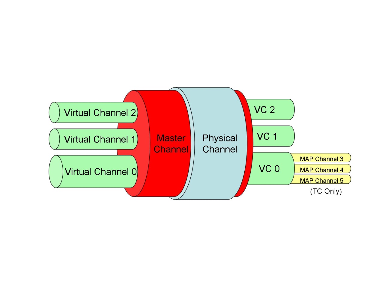
Figure 71 Sharing a physical channel### Convention
Structure diagram
In the remainder of this Standard, sequences of packet fields are presented in structure diagrams as shown in Figure 72.
|
|
repeated N times |
|
|
N
|
packet field 1
|
packet field 2
|
|
unsigned integer
|
Boolean
|
enumerated
|
|
optional |
|
|
Figure 72 An example of a packet field structure diagramFor each field contained in the corresponding structure:
the field name is specified in the first row of the diagram;
the field type is specified in the second row.
Where the presence of a field, or group of fields, is optional, this is indicated by the text "optional" below the corresponding fields. A field or group of fields is optional if its presence is determined at the level of the mission, application process or service instance.
The omission of an optional field can imply that the value is known by both the subservice provider and the subservice user. For example, the subservice provider can use a fixed value or a "current value" which can be set by the subservice user through other means. The subservice provider can even use the values of other preceding fields in the request or report to access a fixed or modifiable lookup table in which the values are contained.
Where a field, or group of fields, constitutes an entry in a fixed-length or a variable-length array, this is indicated above the table by the text "repeated N times", where N is the number of repetitions within the array. In the case of a variable-length array, N is given explicitly at the start of the array. In the case of a fixed-length array, N is known implicitly for the mission.
Bit-field numbering
Each bit in a field (a n-bit field) is identified and numbered from left to right as follows:
The first bit, i.e. the leftmost justified bit on a figure, i.e. the most significant bit, is called "Bit 0";
The second bit is called "Bit 1";
and so on, up to "Bit N1".
A group of 8 adjacent bits is called an octet or a byte.
Packet field type code
General
Each packet field shall be associated to a packet field code that indicates the data type of any value carried by that packet field.
The packet field code specified in this Standard are uniquely identified by the combination of:
- a packet field type code (PTC), and
- a packet field format code (PFC).
The interpretation of each PFC is fully and only dependent on the associated PTC.
Tailoring this Standard for a mission, for each new message type defined for that mission, the packet field type code of each field of that new message type shall be declared when specifying that message type.
Tailoring this Standard for a mission, for each message type field that packet field format code is unknown, the packet field format code of that field shall be declared when specifying the application process that uses the related message type.
The PTC specified in Table 71 shall be used to declare the PTC of each packet field.
Table 71 PTC – packet field type code
|
PTC
|
simple type correspondence
|
|
1
|
Boolean
|
|
2
|
enumerated
|
|
3
|
unsigned integer
|
|
4
|
signed integer
|
|
5
|
real
|
|
6
|
bit-string
|
|
7
|
octet-string
|
|
8
|
character-string
|
|
9
|
absolute time
|
|
10
|
relative time
|
|
11
|
deduced
|
|
12
|
packet
|
The PTC of each packet field shall be declared when specifying the structure of each packet type.
Boolean
Each packet field used to carry Boolean values shall be of PTC 1.
- A Boolean value > 0 denotes TRUE.
- A Boolean value = 0 denotes FALSE.
The PFCs specified in Table 72 shall be used for packet fields carrying Boolean values.
Table 72 PFC for Boolean values
|
PFC
|
format definition
|
|
0
|
1-bit Boolean parameter value
|
|
n > 1
|
The PFC identifies the length in bits of the Boolean parameter value, e.g. PFC = 8 means an 8-bits Boolean parameter value.
|
Enumerated
Each packet field used to carry enumerated values shall be of PTC 2.
- An enumerated value is an unsigned integer value that can be involved in logical and comparative expressions but not in numeric and relational expressions.
- An enumerated value has a meaning that is interpreted as a character-string value. An error code is a typical example (e.g. 0 means "unchecked", 3 means "invalid").
The PFCs specified in Table 73 shall be used for packet fields carrying enumerated values.
Table 73 PFC for enumerated values
|
PFC
|
format definition
|
|
1 to 64
|
The PFC identifies the length in bits of the enumerated parameter, e.g. PFC = 1 means one-bit parameter value.
|
Unsigned integer
Each packet field used to carry unsigned integer values shall be of PTC 3.
Each unsigned integer value shall be encoded with Bit 0 being the most significant bit (MSB) and Bit N1 the least significant bit (LSB).
The PFCs specified in Table 74 shall be used for packet fields carrying unsigned integer values.
Table 74 PFC for unsigned integer values
|
PFC
|
format definition
|
lowest value
|
highest value
|
|
0 to 12
|
(PFC + 4) bits, unsigned
|
|
|
|
13
|
3 octets, unsigned
|
|
|
|
14
|
4 octets, unsigned
|
|
|
|
15
|
6 octets, unsigned
|
|
|
|
16
|
8 octets, unsigned
|
|
|
|
17
|
1 bit, unsigned
|
0
|
1
|
|
18
|
2 bits, unsigned
|
0
|
3
|
|
19
|
3 bits, unsigned
|
0
|
7
|
Signed integer
Each packet field used to carry signed integer values shall be of PTC 4.
Bit 0 of each signed integer parameter shall be used to determine the sign of the parameter value.
- Bit 0 = 0 denotes a positive value.
- Bit 0 = 1 denotes a negative value.
- Negative values are represented as 2’s complement of the absolute value.
The PFCs specified in Table 75 shall be used for packet fields carrying signed integer values.
Table 75 PFC for signed integer values
|
PFC
|
format definition
|
lowest value
|
highest value
|
|
0 to 12
|
(PFC + 4) bits, signed
|
|
|
|
13
|
3 octets, signed
|
|
|
|
14
|
4 octets, signed
|
|
|
|
15
|
6 octets, signed
|
|
|
|
16
|
8 octets, signed
|
|
|
Real
Each packet field used to carry real values shall be of PTC 5.
The PFCs specified in Table 76 shall be used for packet fields carrying real values.
Table 76 PFC for real values
|
PFC
|
format definition
|
|
1
|
4 octets simple precision format (IEEE)
|
|
2
|
8 octets double precision format (IEEE)
|
|
3
|
4 octets simple precision format (MIL-STD)
|
|
4
|
6 octets extended precision format (MIL-STD)
|
|
NOTE 1 The IEEE simple precision and double precision formats are defined in "IEEE 754 Standard for Binary Floating-point Arithmetic" (Reference [7]), see also annex A.1.
| |
Bitstring
Each packet field used to carry bit-string values shall be of PTC 6.
The PFCs specified in Table 77 shall be used for packet fields carrying bit-string values:
Table 77 PFC for bit-string values
|
PFC
|
format definition
|
|
0
|
variable-length bit-string
|
|
n > 0
|
fixed-length bit-string with a number of bits equal to PFC
|
|
NOTE The meaning and interpretation of a bit-string value is application process specific.
| |
The variablelength bitstring shall have the structure specified in Figure 73.
|
variable-length bit-string
| |
|
length
|
data
|
|
unsigned integer
|
N bits
|
|
NOTE The packet field code "N bits" means that a value carried in the data field of a variable-length bit-string has a fixed number of bits that equals to the value carried in the corresponding length field.
| |
Figure 73 PTC 6 PFC 0 structureFor each application process that uses variable-length octet-strings, the PFC of the length field of the variable-length bit-string format shall be declared when specifying that application process.
Each spare field of a telemetry or a telecommand packet shall be of fixed-length PTC 6.
For each spare field of a telemetry or a telecommand packet, all bits of that field shall be set to zero.
For each packet field containing a fixed-length bit-string whose length is deduced, the definition used to deduce that length shall be declared when specifying the related packet field type.
The deduced length corresponds to a fixed length PFC.
For each packet field containing a fixed-length bit-string whose length is deduced, the deduction of the length shall only result from the content of one or more preceding fields of the same packet, of one or more mission constants or a combination of both.
Octetstring
Each packet field used to carry octet-string values shall be of PTC 7.
The PFCs specified in Table 78 shall be used for packet fields carrying octet-string values.
Table 78 PFC for octet-string values
|
PFC
|
format definition
|
|
0
|
Variable-length octet-string
|
|
n > 0
|
Fixed-length octet-string with a number of octets equal to PFC
|
|
NOTE The meaning and interpretation of an octet-string value is application process specific.
| |
The variablelength octetstring shall have the structure specified in Figure 74.
|
variable-length octet-string
| |
|
length
|
data
|
|
unsigned integer
|
N octets
|
|
NOTE The packet field code "N octets" means that a value carried in the data field of a variable-length octet-string has a fixed number of octets that equals to the value carried in the corresponding length field.
| |
Figure 74 PTC 7 PFC 0 structureFor each application process that uses variable-length octet-strings, the PFC of the length field of the variable-length octet-string format shall be declared when specifying that application process.
For each packet field containing a fixed-length octet-string whose length is deduced, the definition used to deduce that length shall be declared when specifying the related packet field type.
The deduced length corresponds to a fixed length PFC.
For each packet field containing a fixed-length octet-string whose length is deduced, the deduction of the length shall only result from the content of one or more preceding fields of the same packet, of one or more mission constants or a combination of both.
Characterstring
Each packet field used to carry character-string values shall be of PTC 8.
The values that character-string parameters can take shall be sequences of visible characters.
Visible characters are defined in ANSI X3.4 (Reference [9]) and represented by their ASCII code on one octet.
The PFCs specified in Table 79 shall be used for packet fields carrying character-string values.
Table 79 PFC for character-string values
|
PFC
|
format definition
|
|
0
|
Variable-length character-string
|
|
n > 0
|
Fixed-length character-string with a number of characters equal to PFC
|
|
NOTE The meaning and interpretation of a character-string value is application process specific.
| |
The variablelength characterstring format shall have the structure specified in Figure 75:
|
variable-length character-string
| |
|
length
|
data
|
|
unsigned integer
|
N characters
|
|
NOTE 1 The packet field code "N character" means that a value carried in the data field of a variable-length character-string has a fixed number of characters that equals to the value carried in the corresponding length field.
| |
Figure 75 PTC 8 PFC 0 structureFor each application process that uses variable-length character-strings, the PFC of the length field of the variable-length character-string format shall be declared when specifying that application process.
For each packet field containing a fixed-length character-string whose length is deduced, the definition used to deduce that length shall be declared when specifying the related packet field type.
The deduced length corresponds to a fixed length PFC.
For each packet field containing a fixed-length character-string whose length is deduced, the deduction of the length shall only result from the content of one or more preceding fields of the same packet, of one or more mission constants or a combination of both.
Absolute time
Each packet field used to carry absolute time values shall be of PTC 9.
Each absolute time parameter value shall be a positive time offset that is a number of seconds and fractions of a second from a given epoch.
- If the CUC format is used, either the standard CCSDS epoch of 1958 January 1 or an Agency defined epoch can be used. In the latter case, the parameter corresponds to a free-running counter that is converted on ground using the applicable time correlation coefficients.
- The CUC format is specified in CCSDS 301.0-B-4. The CCSDS offers means to define CUC coarse time values using 1 to 7 octets and fine time values using 1 to 10 octets. This Standard implements means to define CUC coarse time values using 1 to 4 octets and fine time values using 1 to 10 octets.
If the absolute time parameter has CDS format, the standard CCSDS epoch of 1958 January 1 shall be used.
The CDS format is specified in CCSDS 301.0-B-4.
The PFCs specified in Table 710 shall be used for packet fields carrying absolute time values.
Table 710 PFC for absolute time values
|
PFC
|
format definition
| ||||||||||||||||||||
|
0
|
Explicit definition of time format (CUC or CDS), i.e. including the Pfield
| ||||||||||||||||||||
|
1
|
2 octets day CDS format without a µs field
| ||||||||||||||||||||
|
2
|
2 octets day CDS format with a µs field
| ||||||||||||||||||||
|
3 to 18
|
CUC format with:
| ||||||||||||||||||||
|
19 to 46
|
CUC format with:
| ||||||||||||||||||||
|
NOTE 1 The CUC and CDS time formats are defined in CCSDS 301.0-B-4.
NOTE 3 The full CUC format, i.e. PFC 18 has the structure shown in figure below. The time in seconds from the given Agency epoch is given by .
| |||||||||||||||||||||
Relative time
Each packet field used to carry relative time values shall be of PTC 10.
Each relative time parameter value shall be a positive or a negative time offset that is the number of seconds and fractions of a second from the occurrence time of an event whose identification can be derived from other parameters in the packet (identifying a type of on-board event) or a number of seconds and fractions of a second between two absolute times.
A negative time offset is expressed as the "2’s complement" of the corresponding positive time offset.
The PFCs specified in Table 711 shall be used for packet fields carrying relative time values.
Table 711 PFC for relative time values
|
PFC
|
format definition
| ||||||||||||||
|
2
|
2 octets day CDS format with a µs field
| ||||||||||||||
|
3 to 18
|
CUC format with:
| ||||||||||||||
NOTE The full CUC format, i.e. PFC 18 has the structure shown in figure below. A positive time offset is given by
| |||||||||||||||
Deduced
Each packet field whose structure and format is deduced shall be of PTC 11 PFC 0.
For each packet field whose structure and format is deduced, the definition used to deduce that structure and format shall be declared when specifying the related packet field type.
For each packet field whose structure and format is deduced, the deduction of the structure and format shall only result from the content of one or more preceding fields of the same packet, of one or more mission constants or a combination of both.
Packet
Each packet field used to carry packets shall be of PTC 12.
The PFCs specified in Table 712 shall be used for packet fields carrying packets.
Table 712 PFC for packet values
|
PFC
|
format definition
|
|
0
|
CCSDS telemetry packet compliant with this Standard
|
|
1
|
CCSDS telecommand packet compliant with this Standard
|
|
NOTE For PFC 0 and PFC 1, refer to clause 7.4.
| |
The CCSDS Space Packet
Overview
The CCSDS Space Packet Protocol is defined in CCSDS 133.0-B-1. The generic structure of a CCSDS space packet is shown in Figure 76.
|
packet primary header
|
packet data field
| |||||||
|
packet version number
|
packet ID
|
packet sequence control
|
packet data length
|
packet secondary header
|
user data field
| |||
|
packet type
|
secondary header flag
|
application process ID
|
sequence flags
|
packet sequence count or packet name
| ||||
|
3 bits
|
1 bit
|
1 bit
|
11 bits
|
2 bits
|
14 bits
|
16 bits
|
variable
|
variable
|
|
2 octets
|
2 octets
|
2 octets
|
1 to 65536 octets
| |||||
Figure 76 The space packet structureThe packet version number is set to 0 and identifies it as a space packet defined by CCSDS 133. 0-B-1. A space packet is also referred to as a version 1 CCSDS packet.
The packet type bit distinguishes between telemetry packets, for which this bit is set to 0, and telecommand packets, for which this bit is set to 1.
The secondary header flag indicates the presence or absence of the packet secondary header. With the exception of spacecraft time packets (refer to clause 6.9.4), all telemetry packets defined in this Standard have a packet secondary header field. With the exception of CPDU command packets (refer to clause 9.3.1), all telecommand packets defined in this Standard have a packet secondary header field.
The application process ID uniquely identifies the on-board application process that is source of the telemetry packet and destination of the telecommand packet. Some values of the application process ID field are reserved by the CCSDS standard, making them unavailable for use by PUS services.
The sequence flags are defined by CCSDS but not used by the space packet protocol. This Standard uses the binary value "11" for the sequence flags, to indicate a stand-alone packet. All telemetry packets and telecommand packets defined within this Standard are standalone packets.
The packet sequence count is used for telemetry packets. It is incremented by 1 whenever the source application process releases a packet. The packet sequence count wraps around from 214-1 to zero.
The telecommand packets carry either a packet sequence count or a packet name to identify them within the same communication session. For the purpose of this Standard, the telecommand packet sequence count or packet name field carries an identifier that used in combination with the source identifier specified in clause 7.4.4.1, uniquely identify the telecommand packet.
The packet data length field specifies the length of the packet data field. The value of the unsigned integer in the packet data length field is one less than the number of octets contained within the packet data field. The length of the entire packet, including the packet primary header, is 6 octets more than the length of the packet data field.
The structure of the packet data field depends on the packet type.
for telemetry packets that field is composed of:
the telemetry packet secondary header specified in clause 7.4.3.1;
the telemetry user data field specified in clause 7.4.3.2;
for telecommand packets that field is composed of:
the telecommand packet secondary header specified in clause 7.4.4.1;
the telecommand user data field specified in clause 7.4.4.2.
General
Once a telecommand or a telemetry packet has been generated by an application process, no one shall update that packet.
Telemetry packet data field
Telemetry packet secondary header
With the exception of the spacecraft time packets specified in clauses 6.9.4.2 and 6.9.4.3, all telemetry packets defined in this Standard shall have a telemetry packet secondary header.
Each telemetry packet secondary header shall have the structure specified in Figure 77.
|
TM packet PUS version number
|
spacecraft time reference status
|
message type ID
|
message type counter
|
destination ID
|
time
|
spare
| |
|
service type ID
|
message subtype ID
| ||||||
|
enumerated
|
enumerated
|
enumerated
|
enumerated
|
unsigned integer
|
enumerated
|
absolute time
|
fixed-size bit-string
|
|
|
|
|
|
|
|
|
optional |
|
NOTE The spare field is used to constrain the length of the telemetry packet secondary header to an integral number of words. Its optional presence is driven by requirement 7.4.3.1l.
| |||||||
Figure 77 Packet secondary header for telemetry packetsEach application process shall set the TM packet PUS version number of each telemetry packet it generates to 2.
The TM packet PUS version number reflects the different versions of this Standard.
- Version 0 was used by the ESA PUS (ESA PSS-07-101).
- Version 1 corresponds to the ECSS-E-70-41A.
Each application process that provides the capability to report the spacecraft time reference status used when time tagging telemetry packets shall set the spacecraft time reference status field of each telemetry packet it generates to the status of the on-board time reference used when time tagging that telemetry packet. - For the capability to report the status of the on-board time reference, refer to requirement 5.4.2.1h.
- For the possible values of the spacecraft time reference status, refer to requirement 6.9.4.1c. If the reporting of the spacecraft time reference status is not supported, the spacecraft time reference status field value is set to 0.
- The time tag of the telemetry packet is stored in the time field of the telemetry packet secondary header.
Each application process that does not provide the capability to report the status of the on-board time reference used when time tagging telemetry packets shall set the spacecraft time reference status field of each telemetry packet it generates to 0.
For the capability to report the status of the on-board time reference, refer to requirement 5.4.2.1h.
For each report that it generates, each application process shall set the message type ID field of the corresponding telemetry packet to the message type identifier of that report.
The structure of the message type ID field is driven by requirement 5.3.3.1c.
For each report that it generates, each application process that provides the capability to count the type of generated messages per destination and report the corresponding message type counter shall set the message type counter of the related telemetry packet to the value of the related counter.
For the capability to count the type of generated messages, refer to requirement 5.4.2.1j.
Each application process that does not provide the capability to count the type of generated messages per destination and report the corresponding message type counter shall set the message type counter field of each telemetry packet it generates to 0.
For the capability to count the type of generated messages, refer to requirement 5.4.2.1j.
Each application process shall set the destination ID field of each telemetry packet it generates to the application process user identifier of the application process addressed by the related report.
For the application process user identifier, refer to requirement 5.4.2.1d.
The PFC of the time field of telemetry packets shall be declared when specifying the time service used by the spacecraft.
For the time service, refer to clause 6.9.
Each application process shall set the time field of each telemetry packet it generates to the time tag of the related report.
See requirement 5.4.2.1g.
For each application process, the presence and bit-size of the spare field of the telemetry packet secondary header shall be declared when specifying that application process.
Telemetry user data field
Each telemetry user data field shall have the structure specified in Figure 78.
|
source data
|
spare
|
packet error control
|
|
deduced
|
fixed-size bit-string
|
fixed-size bit-string
|
|
|
optional |
optional |
|
NOTE 1 The structure and format of the source data is deduced from the message type ID. For each report message type specified in this Standard, the structure and format of the source data is specified in clause 8.
| ||
Figure 78 User data field for telemetry packetsThe telemetry padding word size used by each application process shall be declared when specifying that application process.
The telemetry padding word size is the multiple-of-bits number to apply when padding telemetry packets.
For each telemetry packet that it generates, each application process shall ensure that the total length of that packet is an integer multiple of the padding word size declared for that application process by including a user data spare field of the minimum bit-size that results in that integer multiple.
Whether checksumming telemetry packets is used shall be declared when tailoring this standard to the mission.
If checksumming telemetry packets is used for the mission, the type of checksum to use, that is either the ISO standard 16-bits checksum or the CRC standard 16-bits, shall be declared when tailoring this standard to the mission.
- For the CRC standard 16-bits checksum algorithm, refer to annex B.1.
- For the ISO standard 16-bits checksum algorithm, refer to annex B.2.
If checksumming telemetry packets is used for the mission, for each telemetry packet that it generates, each application process shall: - calculate the checksum of that packet, and
- set the calculated value in the packet error control field of that packet.
- The telemetry packet checksum is calculated when all other fields of the packet are complete, and prior to downloading the packet.
- The telemetry packet checksum is used by the ground system to verify the checksum of the complete telemetry packet.
- Checksumming telemetry packets includes also checksumming large telemetry packets, see clause 6.13.3.
Telecommand packet data field
Telecommand packet secondary header
With the exception of the CPDU command packet specified in clause 9, all telecommand packets defined in this Standard shall have a telecommand packet secondary header.
Each telecommand packet secondary header shall have the structure specified in Figure 79.
|
TC packet PUS version number
|
acknowledgement flags
|
message type ID
|
source ID
|
spare
| |
|
service type ID
|
message subtype ID
| ||||
|
enumerated
|
enumerated
|
enumerated
|
enumerated
|
enumerated
|
fixed-size bit-string
|
|
|
|
|
|
|
optional |
|
NOTE The spare field is used to constrain the length of the telecommand packet secondary header to an integral number of words. Its optional presence of is driven by requirement 7.4.4.1g.
| |||||
Figure 79 Packet secondary header for telecommand packetsFor each request that it issues, each application process shall set the TC packet PUS version number to 2.
The TC packet PUS version number reflects the different versions of this Standard.
- Version 0 was used by the ESA PUS (ESA PSS-07-101).
- Version 1 corresponds to the ECSS-E-70-41A.
For each request that it issues, each application process shall set: - the bit 3 of the acknowledgement flags field of the corresponding telecommand packet to:
- 1 if the reporting of the successful acceptance of that request by the destination application process is requested
- 0 otherwise;
- the bit 2 of the acknowledgement flags field of the corresponding telecommand packet to:
- 1 if successful start of execution of that request by the destination application process is requested;
- 0 otherwise;
- the bit 1 of the acknowledgement flags field of the corresponding telecommand packet to:
- 1 if the reporting of the successful progresses of execution of that request by the destination application process is requested;
- 0 otherwise;
- the bit 0 of the acknowledgement flags field of the corresponding telecommand packet to:
- 1 if the reporting of the successful completion of execution of the related request by the destination application process is requested;
- 0 otherwise.
- For item 1, refer to requirement 5.4.11.2.2a.1.
- For item 2, refer to requirement 5.4.11.2.2a.2.
- For item 3, refer to requirement 5.4.11.2.2a.3.
- For item 4, refer to requirement 5.4.11.2.2a.4.
For each request that it issues, each application process shall set the message type ID field of the corresponding telecommand packet to the message type identifier of that request.
The structure of the message type ID field is driven by requirement 5.3.3.1c.
For each request that it issues, each application process shall set the source ID field to its source identifier.
For the source identifier, see requirement 5.4.11.2.1c.
For each application process that issues requests, the presence and bit-size of the spare field of the telecommand packet secondary header shall be declared when specifying that application process.
Telecommand user data field
Each telecommand user data field shall have the structure specified in Figure 710.
|
application data
|
spare
|
packet error control
|
|
deduced
|
fixed-size bit-string
|
fixed-size bit-string
|
|
|
optional |
|
|
NOTE 1 The structure and format of the application data is deduced from the message type ID. For each request type specified in this Standard, the structure and format of the application data is specified in clause 6.
| ||
Figure 710 User data field for telecommand packetsThe telecommand padding word size used for each application process shall be declared when specifying that application process.
The telecommand padding word size is the multiple-of-bits number to apply when padding telecommand packets.
For each telecommand packet that it generates, each application process shall ensure that the total length of that packet is an integer multiple of the padding word size declared for that application process, by including a user data spare field of the minimum bit-size that results in that integer multiple.
The type of checksum to use for checksumming all telecommand packets, which is either the ISO standard 16-bits checksum or the CRC standard 16-bits checksum, shall be declared when tailoring this standard to the mission.
- For the CRC standard 16-bits checksum algorithm, refer to annex B.1.
- For the ISO standard 16-bits checksum algorithm, refer to annex B.2.
For each telecommand packet that it generates, each application process shall: - calculate the checksum of that packet, and
- set the calculated value in the packet error control field of that packet.
- The telecommand packet checksum is calculated when all other fields of the packet are complete, and prior to releasing the packet.
- The checksum of each telecommand packet that is received on-board is verified using the checksum that is contained within the packet error control field of the packet. Refer also to requirement 6.1.3.2b.
Service type interface requirements
ST[01] request verification
General
Each packet transporting a request verification report shall be of service type 1.
Request and reports
TM[1,1] successful acceptance verification report
Each telemetry packet transporting a successful acceptance verification report shall be of message subtype 1.
For the corresponding system requirements, refer to clause 6.1.4.2.
For each telemetry packet transporting a successful acceptance verification report, the source data field shall have the structure specified in Figure 81.
|
request ID
| |||||
|
packet version number
|
packet ID
|
packet sequence control
| |||
|
packet type
|
secondary header flag
|
application process ID
|
sequence flags
|
packet sequence count
| |
|
enumerated
|
enumerated
|
Boolean
|
enumerated
|
enumerated
|
unsigned integer
|
|
NOTE The request ID field alone cannot be used to identify the request since it does not contain the identifier of the source of that request. That source identifier corresponds to the destination identifier of the secondary header of the related telemetry packet, refer to clause 7.4.3.1.
| |||||
Figure 81 Successful acceptance verification report#### TM[1,2] failed acceptance verification report
Each telemetry packet transporting a failed acceptance verification report shall be of message subtype 2.
For the corresponding system requirements, refer to clause 6.1.4.3.
For each telemetry packet transporting a failed acceptance verification report, the source data field shall have the structure specified in Figure 82.
|
request ID
|
failure notice
| ||||||
|
packet version number
|
packet ID
|
packet sequence control
|
code
|
data
| |||
|
packet type
|
secondary header flag
|
application process ID
|
sequence flags
|
packet sequence count
| |||
|
enumerated
|
enumerated
|
Boolean
|
enumerated
|
enumerated
|
unsigned integer
|
enumerated
|
deduced
|
|
|
|
|
|
|
|
|
deduced presence |
|
NOTE The request ID field alone cannot be used to identify the request since it does not contain the identifier of the source of that request. That source identifier corresponds to the destination identifier of the secondary header of the related telemetry packet, refer to clause 7.4.3.1.
| |||||||
Figure 82 Failed acceptance verification report#### TM[1,3] successful start of execution verification report
Each telemetry packet transporting a successful start of execution verification report shall be of message subtype 3.
For the corresponding system requirements, refer to clause 6.1.5.1.1.
For each telemetry packet transporting a successful start of execution verification report, the source data field shall have the structure specified in Figure 83.
|
request ID
| |||||
|
packet version number
|
packet ID
|
packet sequence control
| |||
|
packet type
|
secondary header flag
|
application process ID
|
sequence flags
|
packet sequence count
| |
|
enumerated
|
enumerated
|
Boolean
|
enumerated
|
enumerated
|
unsigned integer
|
|
NOTE The request ID field alone cannot be used to identify the request since it does not contain the identifier of the source of that request. That source identifier corresponds to the destination identifier of the secondary header of the related telemetry packet, refer to clause 7.4.3.1.
| |||||
Figure 83 Successful start of execution verification report#### TM[1,4] failed start of execution verification report
Each telemetry packet transporting a failed start of execution verification report shall be of message subtype 4.
For the corresponding system requirements, refer to clause 6.1.5.1.2.
For each telemetry packet transporting a failed start of execution verification report, the source data field shall have the structure specified in Figure 84.
|
request ID
|
failure notice
| ||||||
|
packet version number
|
packet ID
|
packet sequence control
|
code
|
data
| |||
|
packet type
|
secondary header flag
|
application process ID
|
sequence flags
|
packet sequence count
| |||
|
enumerated
|
enumerated
|
Boolean
|
enumerated
|
enumerated
|
unsigned integer
|
enumerated
|
deduced
|
|
|
|
|
|
|
|
|
deduced presence |
|
NOTE The request ID field alone cannot be used to identify the request since it does not contain the identifier of the source of that request. That source identifier corresponds to the destination identifier of the secondary header of the related telemetry packet, refer to clause 7.4.3.1.
| |||||||
Figure 84 Failed start of execution verification report#### TM[1,5] successful progress of execution verification report
Each telemetry packet transporting a successful progress of execution verification report shall be of message subtype 5.
For the corresponding system requirements, refer to clause 6.1.5.2.1.
For each telemetry packet transporting a successful progress of execution verification report, the source data field shall have the structure specified in Figure 85.
|
request ID
|
step ID
| |||||
|
packet version number
|
packet ID
|
packet sequence control
| ||||
|
packet type
|
secondary header flag
|
application process ID
|
sequence flags
|
packet sequence count
| ||
|
enumerated
|
enumerated
|
Boolean
|
enumerated
|
enumerated
|
unsigned integer
|
enumerated
|
|
NOTE The request ID field alone cannot be used to identify the request since it does not contain the identifier of the source of that request. That source identifier corresponds to the destination identifier of the secondary header of the related telemetry packet, refer to clause 7.4.3.1.
| ||||||
Figure 85 Successful progress of execution verification report#### TM[1,6] failed progress of execution verification report
Each telemetry packet transporting a failed progress of execution verification report shall be of message subtype 6.
For the corresponding system requirements, refer to clause 6.1.5.2.2.
For each telemetry packet transporting a failed progress of execution verification report, the source data field shall have the structure specified in Figure 86.
|
request ID
|
step ID
|
failure notice
| ||||||
|
packet version number
|
packet ID
|
packet sequence control
|
code
|
data
| ||||
|
packet type
|
secondary header flag
|
application process ID
|
sequence flags
|
packet sequence count
| ||||
|
enumerated
|
enumerated
|
Boolean
|
enumerated
|
enumerated
|
unsigned integer
|
enumerated
|
enumerated
|
deduced
|
|
|
|
|
|
|
|
|
|
deduced presence |
|
NOTE The request ID field alone cannot be used to identify the request since it does not contain the identifier of the source of that request. That source identifier corresponds to the destination identifier of the secondary header of the related telemetry packet, refer to clause 7.4.3.1.
| ||||||||
Figure 86 Failed progress of execution verification report#### TM[1,7] successful completion of execution verification report
Each telemetry packet transporting a successful completion of execution verification report shall be of message subtype 7.
For the corresponding system requirements, refer to clause 6.1.5.3.1.
For each telemetry packet transporting a successful completion of execution verification report, the source data field shall have the structure specified in Figure 87.
|
request ID
| |||||
|
packet version number
|
packet ID
|
packet sequence control
| |||
|
packet type
|
secondary header flag
|
application process ID
|
sequence flags
|
packet sequence count
| |
|
enumerated
|
enumerated
|
Boolean
|
enumerated
|
enumerated
|
unsigned integer
|
|
NOTE The request ID field alone cannot be used to identify the request since it does not contain the identifier of the source of that request. That source identifier corresponds to the destination identifier of the secondary header of the related telemetry packet, refer to clause 7.4.3.1.
| |||||
Figure 87 Successful completion of execution verification report#### TM[1,8] failed completion of execution verification report
Each telemetry packet transporting a failed completion of execution verification report shall be of message subtype 8.
For the corresponding system requirements, refer to clause 6.1.5.3.2.
For each telemetry packet transporting a failed completion of execution verification report, the source data field shall have the structure specified in Figure 88.
|
request ID
|
failure notice
| ||||||
|
packet version number
|
packet ID
|
packet sequence control
|
code
|
data
| |||
|
packet type
|
secondary header flag
|
application process ID
|
sequence flags
|
packet sequence count
| |||
|
enumerated
|
enumerated
|
Boolean
|
enumerated
|
enumerated
|
unsigned integer
|
enumerated
|
deduced
|
|
|
|
|
|
|
|
|
deduced presence |
|
NOTE The request ID field alone cannot be used to identify the request since it does not contain the identifier of the source of that request. That source identifier corresponds to the destination identifier of the secondary header of the related telemetry packet, refer to clause 7.4.3.1.
| |||||||
Figure 88 Failed completion of execution verification report#### TM[1,10] failed routing verification report
Each telemetry packet transporting a failed routing verification report shall be of message subtype 10.
For the corresponding system requirements, refer to clause 6.1.3.3.
For each telemetry packet transporting a failed routing verification report, the source data field shall have the structure specified in Figure 89.
|
request ID
|
failure notice
| ||||||
|
packet version number
|
packet ID
|
packet sequence control
|
code
|
data
| |||
|
packet type
|
secondary header flag
|
application process ID
|
sequence flags
|
packet sequence count
| |||
|
enumerated
|
enumerated
|
Boolean
|
enumerated
|
enumerated
|
unsigned integer
|
enumerated
|
deduced
|
|
|
|
|
|
|
|
|
deduced presence |
|
NOTE The request ID field alone cannot be used to identify the request since it does not contain the identifier of the source of that request. That source identifier corresponds to the destination identifier of the secondary header of the related telemetry packet, refer to clause 7.4.3.1.
| |||||||
Figure 89 Failed routing verification report### ST[02] device access
General
Each packet transporting a device access message shall be of service type 2.
Requests and reports
TC[2,1] distribute on/off device commands
Each telecommand packet transporting a request to distribute on/off device commands shall be of message subtype 1.
For the corresponding system requirements, refer to clause 6.2.4.2.
For each telecommand packet transporting a request to distribute on/off device commands, the application data field shall have the structure specified in Figure 810.
|
|
repeated N times |
|
N
|
on/off device address
|
|
unsigned integer
|
enumerated
|
Figure 810 Distribute on/off device commands#### TC[2,2] distribute register load commands
Each telecommand packet transporting a request to distribute register load commands shall be of message subtype 2.
For the corresponding system requirements, refer to clause 6.2.5.2.
For each telecommand packet transporting a request to distribute register load commands, the application data field shall have the structure specified in Figure 811.
|
|
repeated N times |
|
|
N
|
register address
|
register data
|
|
unsigned integer
|
enumerated
|
deduced
|
Figure 811 Distribute register load commands#### TC[2,4] distribute CPDU commands
Each telecommand packet transporting a request to distribute CPDU commands shall be of message subtype 4.
For the corresponding system requirements, refer to clause 6.2.6.2.
For each telecommand packet transporting a request to distribute CPDU commands, the application data field shall have the structure specified in Figure 812.
|
|
repeated N1 times |
||||
|
|
|
|
repeated N2 times |
||
|
N1
|
CPDU ID
|
N2
|
output line ID
|
reserved
|
duration exponential value
|
|
unsigned integer
|
enumerated
|
unsigned integer
|
enumerated
|
bit-string
|
unsigned integer
|
|
optional |
|
|
|
|
|
Figure 812 Distribute CPDU commands#### TC[2,5] distribute register dump commands
Each telecommand packet transporting a request to distribute register dump commands shall be of message subtype 5.
For the corresponding system requirements, refer to clause 6.2.5.3.
For each telecommand packet transporting a request to distribute register dump commands, the application data field shall have the structure specified in Figure 813.
|
|
repeated N times |
|
N
|
register address
|
|
unsigned integer
|
enumerated
|
Figure 813 Distribute register dump commands#### TM[2,6] register dump report
Each telemetry packet transporting a register dump report shall be of message subtype 6.
For the corresponding system requirements, refer to clause 6.2.5.3.
For each telemetry packet transporting a register dump report, the source data field shall have the structure specified in Figure 814.
|
|
repeated N times |
|
|
N
|
register address
|
register data
|
|
unsigned integer
|
enumerated
|
deduced
|
Figure 814 Register dump report#### TC[2,7] distribute physical device commands
Each telecommand packet transporting a request to distribute physical device commands shall be of message subtype 7.
For the corresponding system requirements, refer to clause 6.2.7.1.2.
For each telecommand packet transporting a request to distribute physical device commands, the application data field shall have the structure specified in Figure 815.
|
|
repeated N times |
||
|
N
|
physical device ID
|
protocol-specific data
|
command data
|
|
unsigned integer
|
enumerated
|
deduced
|
deduced
|
Figure 815 Distribute physical device commands#### TC[2,8] acquire data from physical devices
Each telecommand packet transporting a request to acquire data from physical devices shall be of message subtype 8.
For the corresponding system requirements, refer to clause 6.2.7.1.3.
For each telecommand packet transporting a request to acquire data from physical devices, the application data field shall have the structure specified in Figure 816.
|
|
repeated N times |
||
|
N
|
transaction ID
|
physical device ID
|
protocol-specific data
|
|
unsigned integer
|
unsigned integer
|
enumerated
|
deduced
|
Figure 816 Acquire data from physical devices#### TM[2,9] physical device data report
Each telemetry packet transporting a physical device data report shall be of message subtype 9.
For the corresponding system requirements, refer to clause 6.2.7.1.3.
For each telemetry packet transporting a physical device data report, the source data field shall have the structure specified in Figure 817.
|
transaction ID
|
transaction execution status
|
data block
| |
|
data acquisition return code
|
auxiliary data
| ||
|
unsigned integer
|
enumerated
|
deduced
|
deduced
|
|
|
|
deduced presence |
|
Figure 817 Physical device data report#### TC[2,10] distribute logical device commands
Each telecommand packet transporting a request to distribute logical device commands shall be of message subtype 10.
For the corresponding system requirements, refer to clause 6.2.7.2.2.
For each telecommand packet transporting a request to distribute logical device commands, the application data field shall have the structure specified in Figure 818.
|
|
repeated N times |
||
|
N
|
logical device ID
|
command ID
|
command arguments
|
|
unsigned integer
|
enumerated
|
deduced
|
deduced
|
Figure 818 Distribute logical device commands#### TC[2,11] acquire data from logical devices
Each telecommand packet transporting a request to acquire data from logical devices shall be of message subtype 11.
For the corresponding system requirements, refer to clause 6.2.7.2.3.
For each telecommand packet transporting a request to acquire data from logical devices, the application data field shall have the structure specified in Figure 819.
|
|
repeated N times |
||
|
N
|
transaction ID
|
logical device ID
|
parameter ID
|
|
unsigned integer
|
unsigned integer
|
enumerated
|
enumerated
|
Figure 819 Acquire data from logical devices#### TM[2,12] logical device data report
Each telemetry packet transporting a logical device data report shall be of message subtype 12.
For the corresponding system requirements, refer to clause 6.2.7.2.3.
For each telemetry packet transporting a logical device data report, the source data field shall have the structure specified in Figure 820.
|
transaction ID
|
transaction execution status
|
parameter value
| |
|
data acquisition return code
|
auxiliary data
| ||
|
unsigned integer
|
enumerated
|
deduced
|
deduced
|
|
|
|
deduced presence |
|
Figure 820 Logical device data report### ST[03] housekeeping
General
Each packet transporting a housekeeping message shall be of service type 3.
Requests and reports
TC[3,1] create a housekeeping parameter report structure
Each telecommand packet transporting a request to create a housekeeping parameter report structure shall be of message subtype 1.
For the corresponding system requirements, refer to clause 6.3.3.5.1.
For each telecommand packet transporting a request to create a housekeeping parameter report structure, the application data field shall have the structure specified in Figure 821.
|
|
|
|
|
|
repeated NFA times |
||
|
|
|
|
repeated N1 times |
|
|
|
repeated N2 times |
|
housekeeping parameter report structure ID
|
collection interval
|
N1
|
parameter ID
|
NFA
|
super commutated sample repetition number
|
N2
|
parameter ID
|
|
enumerated
|
unsigned integer
|
unsigned integer
|
enumerated
|
unsigned integer
|
unsigned integer
|
unsigned integer
|
enumerated
|
Figure 821 Create a housekeeping parameter report structure#### TC[3,2] create a diagnostic parameter report structure
Each telecommand packet transporting a request to create a diagnostic parameter report structure shall be of message subtype 2.
For the corresponding system requirements, refer to clause 6.3.4.6.
For each telecommand packet transporting a request to create a diagnostic parameter report structure, the application data field shall have the structure specified in Figure 822.
|
|
|
|
|
|
repeated NFA times |
||
|
|
|
|
repeated N1 times |
|
|
|
repeated N2 times |
|
diagnostic parameter report structure ID
|
collection interval
|
N1
|
parameter ID
|
NFA
|
super commutated sample repetition number
|
N2
|
parameter ID
|
|
enumerated
|
unsigned integer
|
unsigned integer
|
enumerated
|
unsigned integer
|
unsigned integer
|
unsigned integer
|
enumerated
|
Figure 822 Create a diagnostic parameter report structure #### TC[3,3] delete housekeeping parameter report structures
Each telecommand packet transporting a request to delete housekeeping parameter report structures shall be of message subtype 3.
For the corresponding system requirements, refer to clause 6.3.3.5.2.
For each telecommand packet transporting a request to delete housekeeping parameter report structures, the application data field shall have the structure specified in Figure 823.
|
|
repeated N times |
|
N
|
housekeeping parameter report structure ID
|
|
unsigned integer
|
enumerated
|
Figure 823 Delete housekeeping parameter report structures #### TC[3,4] delete diagnostic parameter report structures
Each telecommand packet transporting a request to delete diagnostic parameter report structures shall be of message subtype 4.
For the corresponding system requirements, refer to clause 6.3.4.7.
For each telecommand packet transporting a request to delete diagnostic parameter report structures, the application data field shall have the structure specified in Figure 824.
|
|
repeated N times |
|
N
|
diagnostic parameter report structure ID
|
|
unsigned integer
|
enumerated
|
Figure 824 Delete diagnostic parameter report structures #### TC[3,5] enable the periodic generation of housekeeping parameter reports
Each telecommand packet transporting a request to enable the periodic generation of housekeeping parameter reports shall be of message subtype 5.
For the corresponding system requirements, refer to clause 6.3.3.4.1.
For each telecommand packet transporting a request to enable the periodic generation of housekeeping parameter reports, the application data field shall have the structure specified in Figure 825.
|
|
repeated N times |
|
N
|
housekeeping parameter report structure ID
|
|
unsigned integer
|
enumerated
|
Figure 825 Enable the periodic generation of housekeeping parameter reports #### TC[3,6] disable the periodic generation of housekeeping parameter reports
Each telecommand packet transporting a request to disable the periodic generation of housekeeping parameter reports shall be of message subtype 6.
For the corresponding system requirements, refer to clause 6.3.3.4.2.
For each telecommand packet transporting a request to disable the periodic generation of housekeeping parameter reports, the application data field shall have the structure specified in Figure 826.
|
|
repeated N times |
|
N
|
housekeeping parameter report structure ID
|
|
unsigned integer
|
enumerated
|
Figure 826 Disable the periodic generation of housekeeping parameter reports #### TC[3,7] enable the periodic generation of diagnostic parameter reports
Each telecommand packet transporting a request to enable the periodic generation of diagnostic parameter reports shall be of message subtype 7.
For the corresponding system requirements, refer to clause 6.3.4.4.
For each telecommand packet transporting a request to enable the periodic generation of diagnostic parameter reports, the application data field shall have the structure specified in Figure 827.
|
|
repeated N times |
|
N
|
diagnostic parameter report structure ID
|
|
unsigned integer
|
enumerated
|
Figure 827 Enable the periodic generation of diagnostic parameter reports #### TC[3,8] disable the periodic generation of diagnostic parameter reports
Each telecommand packet transporting a request to disable the periodic generation of diagnostic parameter reports shall be of message subtype 8.
For the corresponding system requirements, refer to clause 6.3.4.5.
For each telecommand packet transporting a request to disable the periodic generation of diagnostic parameter reports, the application data field shall have the structure specified in Figure 828.
|
|
repeated N times |
|
N
|
diagnostic parameter report structure ID
|
|
unsigned integer
|
enumerated
|
Figure 828 Disable the periodic generation of diagnostic parameter reports #### TC[3,9] report housekeeping parameter report structures
Each telecommand packet transporting a request to report housekeeping parameter report structures shall be of message subtype 9.
For the corresponding system requirements, refer to clause 6.3.3.6.
For each telecommand packet transporting a request to report housekeeping parameter report structures, the application data field shall have the structure specified in Figure 829.
|
|
repeated N times |
|
N
|
housekeeping parameter report structure ID
|
|
unsigned integer
|
enumerated
|
Figure 829 Report housekeeping parameter report structures #### TM[3,10] housekeeping parameter report structure report
Each telemetry packet transporting a housekeeping parameter report structure report shall be of message subtype 10.
For the corresponding system requirements, refer to clause 6.3.3.6.
For each telemetry packet transporting a housekeeping parameter report structure report, the source data field shall have the structure specified in Figure 830.
|
|
|
|
|
|
|
repeated NFA times |
||
|
|
|
|
|
repeated N1 times |
|
|
|
repeated N2 times |
|
housekeeping parameter report structure ID
|
periodic generation action status
|
collection interval
|
N1
|
parameter ID
|
NFA
|
super commutated sample repetition number
|
N2
|
parameter ID
|
|
enumerated
|
enumerated
|
unsigned integer
|
unsigned integer
|
enumerated
|
unsigned integer
|
unsigned integer
|
unsigned integer
|
enumerated
|
|
|
optional |
|
|
|
|
|
|
|
Figure 830 Housekeeping parameter report structure report #### TC[3,11] report diagnostic parameter report structures
Each telecommand packet transporting a request to report diagnostic parameter report structures shall be of message subtype 11.
For the corresponding system requirements, refer to clause 6.3.4.8.
For each telecommand packet transporting a request to report diagnostic parameter report structures, the application data field shall have the structure specified in Figure 831.
|
|
repeated N times |
|
N
|
diagnostic parameter report structure ID
|
|
unsigned integer
|
enumerated
|
Figure 831 Report diagnostic parameter report structures #### TM[3,12] diagnostic parameter report structure report
Each telemetry packet transporting a diagnostic parameter report structure report shall be of message subtype 12.
For the corresponding system requirements, refer to clause 6.3.4.8.
For each telemetry packet transporting a diagnostic parameter report structure report, the source data field shall have the structure specified in Figure 832.
|
|
|
|
|
|
|
repeated NFA times |
||
|
|
|
|
|
repeated N1 times |
|
|
|
repeated N2 times |
|
diagnostic parameter report structure ID
|
periodic generation action status
|
collection interval
|
N1
|
parameter ID
|
NFA
|
super commutated sample repetition number
|
N2
|
parameter ID
|
|
enumerated
|
enumerated
|
unsigned integer
|
unsigned integer
|
enumerated
|
unsigned integer
|
unsigned integer
|
unsigned integer
|
enumerated
|
Figure 832 Diagnostic parameter report structure report #### TM[3,25] housekeeping parameter report
Each telemetry packet transporting a housekeeping parameter report shall be of message subtype 25.
For the corresponding system requirements, refer to clause 6.3.3.3.
For each telemetry packet transporting a housekeeping parameter report, the source data field shall have the structure specified in Figure 833.
|
|
deduced repeated number of times |
|
housekeeping parameter report structure ID
|
parameter value
|
|
unsigned integer
|
deduced
|
Figure 833 Housekeeping parameter report#### TM[3,26] diagnostic parameter report
Each telemetry packet transporting a diagnostic parameter report shall be of message subtype 26.
For the corresponding system requirements, refer to clause 6.3.4.3.
For each telemetry packet transporting a diagnostic parameter report, the source data field shall have the structure specified in Figure 834.
|
|
deduced repeated number of times |
|
diagnostic parameter report structure ID
|
parameter value
|
|
unsigned integer
|
deduced
|
Figure 834 Diagnostic parameter report structure report#### TC[3,27] generate a one shot report for housekeeping parameter report structures
Each telecommand packet transporting a request to generate a one shot report for housekeeping parameter report structures shall be of message subtype 27.
For the corresponding system requirements, refer to clause 6.3.3.7.
For each telecommand packet transporting a request to generate a one shot report for housekeeping parameter report structures, the application data field shall have the structure specified in Figure 835.
|
|
repeated N times |
|
N
|
housekeeping parameter report structure ID
|
|
unsigned integer
|
enumerated
|
Figure 835 Generate a one shot report for housekeeping parameter report structures#### TC[3,28] generate a one shot report for diagnostic parameter report structures
Each telecommand packet transporting a request to generate a one shot report for diagnostic parameter report structures shall be of message subtype 28.
For the corresponding system requirements, refer to clause 6.3.4.9.
For each telecommand packet transporting a request to generate a one shot report for diagnostic parameter report structures, the application data field shall have the structure specified in Figure 836.
|
|
repeated N times |
|
N
|
diagnostic parameter report structure ID
|
|
unsigned integer
|
enumerated
|
Figure 836 Generate a one shot report for diagnostic parameter report structures #### TC[3,29] append parameters to a housekeeping parameter report structure
Each telecommand packet transporting a request to append parameters to a housekeeping parameter report structure shall be of message subtype 29.
For the corresponding system requirements, refer to clause 6.3.3.8.
For each telecommand packet transporting a request to append parameters to a housekeeping parameter report structure, the application data field shall have the structure specified in Figure 837.
|
|
|
|
|
repeated NFA times |
||
|
|
|
repeated N1 times |
|
|
|
repeated N2 times |
|
housekeeping parameter report structure ID
|
N1
|
parameter ID
|
NFA
|
super commutated sample repetition number
|
N2
|
parameter ID
|
|
enumerated
|
unsigned integer
|
enumerated
|
unsigned integer
|
unsigned integer
|
unsigned integer
|
enumerated
|
Figure 837 Append parameters to a housekeeping parameter report structure#### TC[3,30] append parameters to a diagnostic parameter report structure
Each telecommand packet transporting a request to append parameters to a diagnostic parameter report structure shall be of message subtype 30.
For the corresponding system requirements, refer to clause 6.3.4.10.
For each telecommand packet transporting a request to append parameters to a diagnostic parameter report structure, the application data field shall have the structure specified in Figure 838.
|
|
|
|
|
repeated NFA times |
||
|
|
|
repeated N1 times |
|
|
|
repeated N2 times |
|
diagnostic parameter report structure ID
|
N1
|
parameter ID
|
NFA
|
super commutated sample repetition number
|
N2
|
parameter ID
|
|
enumerated
|
unsigned integer
|
enumerated
|
unsigned integer
|
unsigned integer
|
unsigned integer
|
enumerated
|
Figure 838 Append parameters to a diagnostic parameter report structure#### TC[3,31] modify the collection interval of housekeeping parameter report structures
Each telecommand packet transporting a request to modify the collection interval of housekeeping parameter report structures shall be of message subtype 31.
For the corresponding system requirements, refer to clause 6.3.3.9.
For each telecommand packet transporting a request to modify the collection interval of housekeeping parameter report structures, the application data field shall have the structure specified in Figure 839.
|
|
repeated N times |
|
|
N
|
housekeeping parameter report structure ID
|
collection interval
|
|
unsigned integer
|
enumerated
|
unsigned integer
|
Figure 839 Modify the collection interval of housekeeping parameter report structures#### TC[3,32] modify the collection interval of diagnostic parameter report structures
Each telecommand packet transporting a request to modify the collection interval of diagnostic parameter report structures shall be of message subtype 32.
For the corresponding system requirements, refer to clause 6.3.4.11.
For each telecommand packet transporting a request to modify the collection interval of diagnostic parameter report structures, the application data field shall have the structure specified in Figure 840.
|
|
repeated N times |
|
|
N
|
diagnostic parameter report structure ID
|
collection interval
|
|
unsigned integer
|
enumerated
|
unsigned integer
|
Figure 840 Modify the collection interval of diagnostic parameter report structures#### TC[3,33] report the periodic generation properties of housekeeping parameter report structures
Each telecommand packet transporting a request to report the periodic generation properties of housekeeping parameter report structures shall be of message subtype 33.
For the corresponding system requirements, refer to clause 6.3.3.10.
For each telecommand packet transporting a request to report the periodic generation properties of housekeeping parameter report structures, the application data field shall have the structure specified in Figure 841.
|
|
repeated N times |
|
N
|
housekeeping parameter report structure ID
|
|
unsigned integer
|
enumerated
|
Figure 841 Report the periodic generation properties of housekeeping parameter report structures#### TC[3,34] report the periodic generation properties of diagnostic parameter report structures
Each telecommand packet transporting a request to report the periodic generation properties of diagnostic parameter report structures shall be of message subtype 34.
For the corresponding system requirements, refer to clause 6.3.4.12.
For each telecommand packet transporting a request to report the periodic generation properties of diagnostic parameter report structures, the application data field shall have the structure specified in Figure 842.
|
|
repeated N times |
|
N
|
diagnostic parameter report structure ID
|
|
unsigned integer
|
enumerated
|
Figure 842 Report the periodic generation properties of diagnostic parameter report structures#### TM[3,35] housekeeping parameter report periodic generation properties report
Each telemetry packet transporting a housekeeping parameter report periodic generation properties report shall be of message subtype 35.
For the corresponding system requirements, refer to clause 6.3.3.10.
For each telemetry packet transporting a housekeeping parameter report periodic generation properties report, the source data field shall have the structure specified in Figure 843.
|
|
repeated N times |
||
|
N
|
housekeeping parameter report structure ID
|
periodic generation action status
|
collection interval
|
|
unsigned integer
|
enumerated
|
enumerated
|
unsigned integer
|
Figure 843 Housekeeping parameter report periodic generation properties report#### TM[3,36] diagnostic parameter report periodic generation properties report
Each telemetry packet transporting a diagnostic parameter report periodic generation properties report shall be of message subtype 36.
For the corresponding system requirements, refer to clause 6.3.4.12.
For each telemetry packet transporting a diagnostic parameter report periodic generation properties report, the source data field shall have the structure specified in Figure 844.
|
|
repeated N times |
||
|
N
|
diagnostic parameter report structure ID
|
periodic generation action status
|
collection interval
|
|
unsigned integer
|
enumerated
|
enumerated
|
unsigned integer
|
Figure 844 Diagnostic parameter report periodic generation properties report#### TC[3,37] apply parameter functional reporting configurations
Each telecommand packet transporting a request to apply parameter functional reporting configurations shall be of message subtype 37.
For the corresponding system requirements, refer to clause 6.3.5.3.
For each telecommand packet transporting a request to apply parameter functional reporting configurations, the application data field shall have the structure specified in Figure 845.
|
|
|
repeated N times |
|
configuration execution flag
|
N
|
parameter functional reporting definition ID
|
|
enumerated
|
unsigned integer
|
enumerated
|
|
NOTE For the configuration execution flag enumerated values, see requirement 8.3.3b.
| ||
Figure 845 Apply parameter functional reporting configurations#### TC[3,38] create a parameter functional reporting definition
Each telecommand packet transporting a request to create a parameter functional reporting definition shall be of message subtype 38.
For the corresponding system requirements, refer to clause 6.3.5.4.1.
For each telecommand packet transporting a request to create a parameter functional reporting definition, the application data field shall have the structure specified in Figure 846.
|
|
|
repeated N1 times |
|||||
|
|
|
|
|
repeated N2 times |
|||
|
parameter functional reporting definition ID
|
N1
|
application process ID
|
N2
|
parameter report structure type
|
parameter report structure ID
|
periodic generation action status
|
collection interval
|
|
enumerated
|
unsigned integer
|
enumerated
|
unsigned integer
|
enumerated
|
enumerated
|
enumerated
|
unsigned integer
|
|
|
optional |
|
|
|
|
|
|
|
NOTE For the parameter report structure type values, see requirement 8.3.3a.
| |||||||
Figure 846 Create a parameter functional reporting definition#### TC[3,39] delete parameter functional reporting definitions
Each telecommand packet transporting a request to delete parameter functional reporting definitions shall be of message subtype 39.
For the corresponding system requirements, refer to clause 6.3.5.4.2.
For each telecommand packet transporting a request to delete parameter functional reporting definitions, the application data field shall have the structure specified in Figure 847.
|
|
repeated N times |
|
N
|
parameter functional reporting definition ID
|
|
unsigned integer
|
enumerated
|
Figure 847 Delete parameter functional reporting definitions#### TC[3,40] report parameter functional reporting definitions
Each telecommand packet transporting a request to report parameter functional reporting definitions shall be of message subtype 40.
For the corresponding system requirements, refer to clause 6.3.5.5.
For each telecommand packet transporting a request to report parameter functional reporting definitions, the application data field shall have the structure specified in Figure 848.
|
|
repeated N times |
|
N
|
parameter functional reporting definition ID
|
|
unsigned integer
|
enumerated
|
Figure 848 Report parameter functional reporting definitions#### TM[3,41] parameter functional reporting definition report
Each telemetry packet transporting a parameter functional reporting definition report shall be of message subtype 41.
For the corresponding system requirements, refer to clause 6.3.5.5.
For each telemetry packet transporting a parameter functional reporting definition report, the source data field shall have the structure specified in Figure 849.
|
|
|
repeated N1 times |
|||||
|
|
|
|
|
repeated N2 times |
|||
|
parameter functional reporting definition ID
|
N1
|
application process ID
|
N2
|
parameter report structure type
|
parameter report structure ID
|
periodic generation action status
|
collection interval
|
|
enumerated
|
unsigned integer
|
enumerated
|
unsigned integer
|
enumerated
|
enumerated
|
enumerated
|
unsigned integer
|
|
|
optional |
|
|
|
|
|
|
|
NOTE 1 The optional presence of the N1 and the application process ID fields is driven by requirement 6.3.5.2b.
| |||||||
Figure 849 Parameter functional reporting definition report#### TC[3,42] add parameter report definitions to a parameter functional reporting definition
Each telecommand packet transporting a request to add parameter report definitions to a parameter functional reporting definition shall be of message subtype 42.
For the corresponding system requirements, refer to clause 6.3.5.6.1.
For each telecommand packet transporting a request to add parameter report definitions to a parameter functional reporting definition, the application data field shall have the structure specified in Figure 850.
|
|
|
repeated N1 times |
|||||
|
|
|
|
|
repeated N2 times |
|||
|
parameter functional reporting definition ID
|
N1
|
application process ID
|
N2
|
parameter report structure type
|
parameter report structure ID
|
periodic generation action status
|
collection interval
|
|
enumerated
|
unsigned integer
|
enumerated
|
unsigned integer
|
enumerated
|
enumerated
|
enumerated
|
unsigned integer
|
|
|
optional |
|
|
|
|
|
|
|
NOTE For the parameter report structure type values, see requirement 8.3.3a.
| |||||||
Figure 850 Add parameter report definitions to a parameter functional reporting definition#### TC[3,43] remove parameter report definitions from a parameter functional reporting definition
Each telecommand packet transporting a request to remove parameter report definitions from a parameter functional reporting definition shall be of message subtype 43.
For the corresponding system requirements, refer to clause 6.3.5.6.2.
For each telecommand packet transporting a request to remove parameter report definitions from a parameter functional reporting definition, the application data field shall have the structure specified in Figure 851.
|
|
|
repeated N1 times |
|||
|
|
|
|
|
repeated N2 times |
|
|
parameter functional reporting definition ID
|
N1
|
application process ID
|
N2
|
parameter report structure type
|
parameter report structure ID
|
|
enumerated
|
unsigned integer
|
enumerated
|
unsigned integer
|
enumerated
|
enumerated
|
|
|
optional |
|
|
|
|
|
NOTE For the parameter report structure type values, see requirement 8.3.3a.
| |||||
Figure 851 Remove parameter report definitions from a parameter functional reporting definition#### TC[3,44] modify the periodic generation properties of parameter report definitions of a parameter functional reporting definition
Each telecommand packet transporting a request to modify the periodic generation properties of parameter report definitions of a parameter functional reporting definition shall be of message subtype 44.
For the corresponding system requirements, refer to clause 6.3.5.6.3.
For each telecommand packet transporting a request to modify the periodic generation properties of parameter report definitions of a parameter functional reporting definition, the application data field shall have the structure specified in Figure 852.
|
|
|
repeated N1 times |
|||||
|
|
|
|
|
repeated N2 times |
|||
|
parameter functional reporting definition ID
|
N1
|
application process ID
|
N2
|
parameter report structure type
|
parameter report structure ID
|
periodic generation action status
|
collection interval
|
|
enumerated
|
unsigned integer
|
enumerated
|
unsigned integer
|
enumerated
|
enumerated
|
enumerated
|
unsigned integer
|
|
|
optional |
|
|
|
|
|
|
|
NOTE For the parameter report structure type values, see requirement 8.3.3a.
| |||||||
Figure 852 Modify the periodic generation properties of parameter report definitions of a parameter functional reporting definition### Enumeration
The values of the parameter report structure type shall be as specified in Table 81.
Table 81 Service 3 parameter report structure type
|
engineering value
|
raw value
|
|
"housekeeping"
|
25
|
|
"diagnostic"
|
26
|
The values of the configuration execution flag shall be as specified in Table 82.
Table 82 Service 3 configuration execution flag
|
engineering value
|
raw value
|
|
"non-exclusive"
|
0
|
|
"exclusive"
|
1
|
ST[04] parameter statistics reporting
General
Each packet transporting a parameter statistics reporting message shall be of service type 4.
Requests and reports
TC[4,1] report the parameter statistics
Each telecommand packet transporting a request to report the parameter statistics shall be of message subtype 1.
For the corresponding system requirements, refer to clause 6.4.5.2.
For each telecommand packet transporting a request to report the parameter statistics, the application data field shall have the structure specified in Figure 853.
|
reset flag
|
|
Boolean
|
|
optional |
Figure 853 Report the parameter statistics#### TM[4,2] parameter statistics report
Each telemetry packet transporting a parameter statistics report shall be of message subtype 2.
For the corresponding system requirements, refer to clause 6.4.5.3.
For each telemetry packet transporting a parameter statistics report, the source data field shall have the structure specified in Figure 854.
|
|
|
|
repeated N times |
|||||||
|
start time
|
end time
|
N
|
parameter ID
|
number of samples
|
maximum
|
minimum
|
mean value
|
standard deviation value
| ||
|
value
|
time
|
value
|
time
| |||||||
|
absolute time
|
absolute time
|
unsigned integer
|
enumerated
|
unsigned integer
|
deduced
|
absolute time
|
deduced
|
absolute time
|
deduced
|
deduced
|
|
|
|
|
|
|
|
|
|
|
|
optional |
|
NOTE The formats of the max value field, the min value field, the mean value field and the standard deviation value field are specific to the parameter identified by the associated parameter ID field.
| ||||||||||
Figure 854 Parameter statistics report#### TC[4,3] reset the parameter statistics
Each telecommand packet transporting a request to reset the parameter statistics shall be of message subtype 3.
For the corresponding system requirements, refer to clause 6.4.4.
For each telecommand packet transporting a request to reset the parameter statistics, the application data field shall be omitted.
TC[4,4] enable the periodic parameter statistics reporting
Each telecommand packet transporting a request to enable the periodic parameter statistics reporting shall be of message subtype 4.
For the corresponding system requirements, refer to clause 6.4.6.2.
For each telecommand packet transporting a request to enable the periodic parameter statistics reporting, the application data field shall have the structure specified in Figure 855.
|
reporting interval
|
|
relative time
|
|
optional |
Figure 855 Enable the periodic parameter statistics reporting#### TC[4,5] disable the periodic parameter statistics reporting
Each telecommand packet transporting a request to disable the periodic parameter statistics reporting shall be of message subtype 5.
For the corresponding system requirements, refer to clause 6.4.6.3.
For each telecommand packet transporting a request to disable the periodic parameter statistics reporting, the application data field shall be omitted.
TC[4,6] add or update parameter statistics definitions
Each telecommand packet transporting a request to add or update parameter statistics definitions shall be of message subtype 6.
For the corresponding system requirements, refer to clause 6.4.7.1.
For each telecommand packet transporting a request to add or update parameter statistics definitions, the application data field shall have the structure specified in Figure 856.
|
|
repeated N times |
|
|
N
|
parameter ID
|
sampling interval
|
|
unsigned integer
|
enumerated
|
relative time
|
|
|
|
optional |
Figure 856 Add or update parameter statistics definitions#### TC[4,7] delete parameter statistics definitions
Each telecommand packet transporting a request to delete parameter statistics definitions shall be of message subtype 7.
For the corresponding system requirements, refer to clause 6.4.7.2.
For each telecommand packet transporting a request to delete parameter statistics definitions, the application data field shall have the structure specified in Figure 857.
|
|
repeated N times |
|
N
|
parameter ID
|
|
unsigned integer
|
enumerated
|
Figure 857 Delete parameter statistics definitionsTo delete all parameter statistics definitions, N shall be set to 0.
TC[4,8] report the parameter statistics definitions
Each telecommand packet transporting a request to report the parameter statistics definitions shall be of message subtype 8.
For the corresponding system requirements, refer to clause 6.4.7.3.
For each telecommand packet transporting a request to report the parameter statistics definitions, the application data field shall be omitted.
TM[4,9] parameter statistics definition report
Each telemetry packet transporting a parameter statistics definition report shall be of message subtype 9.
For the corresponding system requirements, refer to clause 6.4.7.3.
For each telemetry packet transporting a parameter statistics definition report, the source data field shall have the structure specified in Figure 858.
|
|
|
repeated N times |
|
|
reporting interval
|
N
|
parameter ID
|
sampling interval
|
|
relative time
|
unsigned integer
|
enumerated
|
relative time
|
|
optional |
|
|
optional |
Figure 858 Parameter statistics definition reportWhenever a parameter statistics definition report is generated, if the reporting interval field is present and the periodic reporting is not enabled, the reporting interval field value shall be set to zero seconds.
ST[05] event reporting
General
Each packet transporting an event reporting message shall be of service type 5.
Requests and reports
TM[5,1] informative event report
Each telemetry packet transporting an informative event report shall be of message subtype 1.
For the corresponding system requirements, refer to clause 6.5.4.
For each telemetry packet transporting an informative event report, the source data field shall have the structure specified in Figure 859.
|
event definition ID
|
auxiliary data
|
|
enumerated
|
deduced
|
|
|
deduced presence |
|
NOTE The event definition ID, together with the application process ID, identifies an event definition and as such the presence and structure of the auxiliary data field.
| |
Figure 859 Informative event report#### TM[5,2] low severity anomaly report
Each telemetry packet transporting a low severity anomaly report shall be of message subtype 2.
For the corresponding system requirements, refer to clause 6.5.4.
For each telemetry packet transporting a low severity anomaly report, the source data field shall have the structure specified in Figure 860.
|
event definition ID
|
auxiliary data
|
|
enumerated
|
deduced
|
|
|
deduced presence |
|
NOTE The event definition ID, together with the application process ID, identifies an event definition and as such the presence and structure of the auxiliary data field.
| |
Figure 860 Low severity anomaly report#### TM[5,3] medium severity anomaly report
Each telemetry packet transporting a medium severity anomaly report shall be of message subtype 3.
For the corresponding system requirements, refer to clause 6.5.4.
For each telemetry packet transporting a medium severity anomaly report, the source data field shall have the structure specified in Figure 861.
|
event definition ID
|
auxiliary data
|
|
enumerated
|
deduced
|
|
|
deduced presence |
|
NOTE The event definition ID, together with the application process ID, identifies an event definition and as such the presence and structure of the auxiliary data field.
| |
Figure 861 Medium severity anomaly report#### TM[5,4] High severity anomaly report
Each telemetry packet transporting a high severity anomaly report shall be of message subtype 4.
For the corresponding system requirements, refer to clause 6.5.4.
For each telemetry packet transporting a high severity anomaly report, the source data field shall have the structure specified in Figure 862.
|
event definition ID
|
auxiliary data
|
|
enumerated
|
deduced
|
|
|
deduced presence |
|
NOTE The event definition ID, together with the application process ID, identifies an event definition and as such the presence and structure of the auxiliary data field.
| |
Figure 862 High severity anomaly report#### TC[5,5] enable the report generation of event definitions
Each telecommand packet transporting a request to enable the report generation of event definitions shall be of message subtype 5.
For the corresponding system requirements, refer to clause 6.5.5.2.
For each telecommand packet transporting a request to enable the report generation of event definitions, the application data field shall have the structure specified in Figure 863.
|
|
repeated N times |
|
N
|
event definition ID
|
|
unsigned integer
|
enumerated
|
Figure 863 Enable the report generation of event definitions#### TC[5,6] disable the report generation of event definitions
Each telecommand packet transporting a request to disable the report generation of event definitions shall be of message subtype 6.
For the corresponding system requirements, refer to clause 6.5.5.3.
For each telecommand packet transporting a request to disable the report generation of event definitions, the application data field shall have the structure specified in Figure 864.
|
|
repeated N times |
|
N
|
event definition ID
|
|
unsigned integer
|
enumerated
|
Figure 864 Disable the report generation of event definitions#### TC[5,7] report the list of disabled event definitions
Each telecommand packet transporting a request to report the list of disabled event definitions shall be of message subtype 7.
For the corresponding system requirements, refer to clause 6.5.5.4.
For each telecommand packet transporting a request to report the list of disabled event definitions, the application data field shall be omitted.
TM[5,8] disabled event definitions list report
Each telemetry packet transporting a disabled event definitions list report shall be of message subtype 8.
For the corresponding system requirements, refer to clause 6.5.5.4.
For each telemetry packet transporting a disabled event definitions list report, the source data field shall have the structure specified in Figure 865.
|
|
repeated N times |
|
N
|
event definition ID
|
|
unsigned integer
|
enumerated
|
Figure 865 Disabled event definitions list report### ST[06] memory management
General
Each packet transporting a memory management message shall be of service type 6.
Whether the memory management service supports multiple instructions within memory management related requests shall be declared when specifying that service.
Requests and reports
TC[6,1] load object memory data
Each telecommand packet transporting a request to load object memory data shall be of message subtype 1.
For the corresponding system requirements, refer to clause 6.6.4.4.
For each telecommand packet transporting a request to load object memory data, the application data field shall have the structure specified in Figure 866.
|
|
|
|
repeated N times |
|||
|
memory ID
|
base
|
N
|
offset
|
data to load
|
checksum
| |
|
length
|
data
| |||||
|
enumerated
|
deduced
|
unsigned integer
|
unsigned integer
|
variable octet-string
|
bit-string
| |
|
optional |
|
|
|
|
|
optional |
|
NOTE The PFC of the length field of the data to load is driven by requirement 7.3.8d.
| ||||||
Figure 866 Load object memory data#### TC[6,2] load raw memory data areas
Each telecommand packet transporting a request to load raw memory data areas shall be of message subtype 2.
For the corresponding system requirements, refer to clause 6.6.3.3.1.
For each telecommand packet transporting a request to load raw memory data areas, the application data field shall have the structure specified in Figure 867.
|
|
|
repeated N times |
|||
|
memory ID
|
N
|
start address
|
data to load
|
checksum
| |
|
length
|
data
| ||||
|
enumerated
|
unsigned integer
|
unsigned integer
|
variable octet-string
|
bit-string
| |
|
optional |
|
|
|
|
optional |
|
NOTE The PFC of the length field of the data to load is driven by requirement 7.3.8d.
| |||||
Figure 867 Load raw memory data areas#### TC[6,3] dump object memory data
Each telecommand packet transporting a request to dump object memory data shall be of message subtype 3.
For the corresponding system requirements, refer to clause 6.6.4.5.
For each telecommand packet transporting a request to dump object memory data, the application data field shall have the structure specified in Figure 868.
|
|
|
|
repeated N times |
|
|
memory ID
|
base
|
N
|
offset
|
length
|
|
enumerated
|
deduced
|
unsigned integer
|
unsigned integer
|
unsigned integer
|
|
optional |
|
|
|
|
Figure 868 Dump object memory data#### TM[6,4] dumped object memory data report
Each telemetry packet transporting a dumped object memory data report shall be of message subtype 4.
For the corresponding system requirements, refer to clause 6.6.4.5.
For each telemetry packet transporting a dumped object memory data report, the source data field shall have the structure specified in Figure 869.
|
|
|
|
repeated N times |
|||
|
memory ID
|
base
|
N
|
offset
|
dumped data
|
checksum
| |
|
length
|
data
| |||||
|
enumerated
|
deduced
|
unsigned integer
|
unsigned integer
|
variable octet-string
|
bit-string
| |
|
optional |
|
|
|
|
|
optional |
|
NOTE The PFC of the length field of the dumped data is driven by requirement 7.3.8d.
| ||||||
Figure 869 Dumped object memory data report#### TC[6,5] dump raw memory data
Each telecommand packet transporting a request to dump raw memory data shall be of message subtype 5.
For the corresponding system requirements, refer to clause 6.6.3.4.
For each telecommand packet transporting a request to dump raw memory data, the application data field shall have the structure specified in Figure 870.
|
|
|
repeated N times |
|
|
memory ID
|
N
|
start address
|
length
|
|
enumerated
|
unsigned integer
|
unsigned integer
|
unsigned integer
|
|
optional |
|
|
|
Figure 870 Dump raw memory data#### TM[6,6] dumped raw memory data report
Each telemetry packet transporting a dumped raw memory data report shall be of message subtype 6.
For the corresponding system requirements, refer to clause 6.6.3.4.
For each telemetry packet transporting a dumped raw memory data report, the source data field shall have the structure specified in Figure 871.
|
|
|
repeated N times |
|||
|
memory ID
|
N
|
start address
|
dumped data
|
checksum
| |
|
length
|
data
| ||||
|
enumerated
|
unsigned integer
|
unsigned integer
|
variable octet-string
|
bit-string
| |
|
optional |
|
|
|
|
optional |
|
NOTE The PFC of the length field of the dumped data is driven by requirement 7.3.8d.
| |||||
Figure 871 Dumped raw memory data report#### TC[6,7] check object memory data
Each telecommand packet transporting a request to check object memory data shall be of message subtype 7.
For the corresponding system requirements, refer to clause 6.6.4.6.
For each telecommand packet transporting a request to check object memory data, the application data field shall have the structure specified in Figure 872.
|
|
|
|
repeated N times |
|
|
memory ID
|
base
|
N
|
offset
|
length
|
|
enumerated
|
deduced
|
unsigned integer
|
unsigned integer
|
unsigned integer
|
|
optional |
|
|
|
|
Figure 872 Check object memory data#### TM[6,8] checked object memory data report
Each telemetry packet transporting a checked object memory data report shall be of message subtype 8.
For the corresponding system requirements, refer to clause 6.6.4.6.
For each telemetry packet transporting a checked object memory data report, the source data field shall have the structure specified in Figure 873.
|
|
|
|
repeated N times |
||
|
memory ID
|
base
|
N
|
offset
|
length
|
checksum
|
|
enumerated
|
deduced
|
unsigned integer
|
unsigned integer
|
unsigned integer
|
bit-string
|
|
optional |
|
|
|
|
|
Figure 873 Checked object memory data report#### TC[6,9] check raw memory data
Each telecommand packet transporting a request to check raw memory data shall be of message subtype 9.
For the corresponding system requirements, refer to clause 6.6.3.5.
For each telecommand packet transporting a request to check raw memory data, the application data field shall have the structure specified in Figure 874.
|
|
|
repeated N times |
|
|
memory ID
|
N
|
start address
|
length
|
|
enumerated
|
unsigned integer
|
unsigned integer
|
unsigned integer
|
|
optional |
|
|
|
Figure 874 Check raw memory data#### TM[6,10] checked raw memory data report
Each telemetry packet transporting a checked raw memory data report shall be of message subtype 10.
For the corresponding system requirements, refer to clause 6.6.3.5.
For each telemetry packet transporting a checked raw memory data report, the source data field shall have the structure specified in Figure 875.
|
|
|
repeated N times |
||
|
memory ID
|
N
|
start address
|
length
|
checksum
|
|
enumerated
|
unsigned integer
|
unsigned integer
|
unsigned integer
|
bit-string
|
|
optional |
|
|
|
|
Figure 875 Checked raw memory data report#### TC[6,11] load a raw memory atomic data area in a non-interruptible transaction
Each telecommand packet transporting a request to load a raw memory atomic data area in a non-interruptible transaction shall be of message subtype 11.
For the corresponding system requirements, refer to clause 6.6.3.3.2.
For each telecommand packet transporting a request to load a raw memory atomic data area in a non-interruptible transaction, the application data field shall have the structure specified in Figure 876.
|
memory ID
|
start address
|
bit mask
|
data to load
|
|
enumerated
|
unsigned integer
|
fixed octet-string
|
fixed octet-string
|
|
optional |
|
|
|
|
NOTE The deduced size of the bit mask field and of the data to load field is driven by requirement 5.4.3.3.1c.1. The size of each of these fields is equal to the size of the memory access alignment constraint defined by the memory ID.
| |||
Figure 876 Load a raw memory atomic data area in a non-interruptible transaction#### TC[6,12] abort all memory dumps
Each telecommand packet transporting a request to abort all memory dumps shall be of message subtype 12.
For the corresponding system requirements, refer to clause 6.6.5.1.
For each telecommand packet transporting a request to abort all memory dumps, the application data field shall be omitted.
TC[6,13] enable the scrubbing of a memory
Each telecommand packet transporting a request to enable the scrubbing of a memory shall be of message subtype 13.
For the corresponding system requirements, refer to clause 6.6.6.1.4.
For each telecommand packet transporting a request to enable the scrubbing of a memory, the application data field shall have the structure specified in Figure 877.
|
memory ID
|
|
enumerated
|
|
optional |
Figure 877 Enable the scrubbing of a memory#### TC[6,14] disable the scrubbing of a memory
Each telecommand packet transporting a request to disable the scrubbing of a memory shall be of message subtype 14.
For the corresponding system requirements, refer to clause 6.6.6.1.5.
For each telecommand packet transporting a request to disable the scrubbing of a memory, the application data field shall have the structure specified in Figure 878.
|
memory ID
|
|
enumerated
|
|
optional |
Figure 878 Disable the scrubbing of a memory#### TC[6,15] enable the write protection of a memory
Each telecommand packet transporting a request to enable the write protection of a memory shall be of message subtype 15.
For the corresponding system requirements, refer to clause 6.6.6.2.4.
For each telecommand packet transporting a request to enable the write protection of a memory, the application data field shall have the structure specified in Figure 879.
|
memory ID
|
|
enumerated
|
|
optional |
Figure 879 Enable the write protection of a memory#### TC[6,16] disable the write protection of a memory
Each telecommand packet transporting a request to disable the write protection of a memory shall be of message subtype 16.
For the corresponding system requirements, refer to clause 6.6.6.2.5.
For each telecommand packet transporting a request to disable the write protection of a memory, the application data field shall have the structure specified in Figure 880.
|
memory ID
|
|
enumerated
|
|
optional |
Figure 880 Disable the write protection of a memory#### TC[6,17] check an object memory object
Each telecommand packet transporting a request to check an object memory object shall be of message subtype 17.
For the corresponding system requirements, refer to clause 6.6.4.7.
For each telecommand packet transporting a request to check an object memory object, the application data field shall have the structure specified in Figure 881.
|
memory ID
|
base
|
|
enumerated
|
deduced
|
|
optional |
|
Figure 881 Check an object memory object#### TM[6,18] checked object memory object report
Each telemetry packet transporting a checked object memory object report shall be of message subtype 18.
For the corresponding system requirements, refer to clause 6.6.4.7.
For each telemetry packet transporting a checked object memory object report, the source data field shall have the structure specified in Figure 882.
|
memory ID
|
base
|
length
|
checksum
|
|
enumerated
|
deduced
|
unsigned integer
|
bit-string
|
|
optional |
|
|
|
Figure 882 Checked object memory object report#### TC[6,19] load raw memory data areas by reference
Each telecommand packet transporting a request to load raw memory data areas by reference shall be of message subtype 19.
For the corresponding system requirements, refer to clause 6.6.3.6.
For each telecommand packet transporting a request to load raw memory data areas, the application data field shall have the structure specified in Figure 883.
|
|
|
|
|
repeated N times |
|||
|
memory ID
|
file path
|
N
|
start address
|
offset in file
|
length
|
checksum
| |
|
repository path
|
file name
| ||||||
|
enumerated
|
variable character-string
|
variable character-string
|
unsigned integer
|
unsigned integer
|
unsigned integer
|
unsigned integer
|
bit-string
|
|
optional |
|
|
|
|
|
|
optional |
Figure 883 Load raw memory data areas by reference#### TC[6,20] dump raw memory data areas to file
Each telecommand packet transporting a request to dump raw memory data areas to file shall be of message subtype 20.
For the corresponding system requirements, refer to clause 6.6.3.7.
For each telecommand packet transporting a request to dump raw memory data areas to file, the application data field shall have the structure specified in Figure 884.
|
|
|
|
|
repeated N times |
|
|
memory ID
|
file path
|
N
|
start address
|
length
| |
|
repository path
|
file name
| ||||
|
enumerated
|
variable character-string
|
variable character-string
|
unsigned integer
|
unsigned integer
|
unsigned integer
|
|
optional |
|
|
|
|
|
Figure 884 Dump raw memory data areas to file#### TC[6,21] load object memory data areas by reference
Each telecommand packet transporting a request to load object memory data areas by reference shall be of message subtype 21.
For the corresponding system requirements, refer to clause 6.6.4.8.
For each telecommand packet transporting a request to load object memory data areas, the application data field shall have the structure specified in Figure 885.
|
|
|
|
|
|
repeated N times |
|||
|
memory ID
|
base
|
file path
|
N
|
destination offset
|
offset in file
|
length
|
checksum
| |
|
repository path
|
file name
| |||||||
|
enumerated
|
deduced
|
variable character-string
|
variable character-string
|
unsigned integer
|
unsigned integer
|
unsigned integer
|
unsigned integer
|
bit-string
|
|
optional |
|
|
|
|
|
|
|
optional |
Figure 885 Load object memory data areas by reference#### TC[6,22] dump object memory data areas to file
Each telecommand packet transporting a request to dump object memory data areas to file shall be of message subtype 20.
For the corresponding system requirements, refer to clause 6.6.4.9.
For each telecommand packet transporting a request to dump object memory data areas to file, the application data field shall have the structure specified in Figure 886.
|
|
|
|
|
|
repeated N times |
|
|
memory ID
|
base
|
file path
|
N
|
offset
|
length
| |
|
repository path
|
file name
| |||||
|
enumerated
|
deduced
|
variable character-string
|
variable character-string
|
unsigned integer
|
unsigned integer
|
unsigned integer
|
|
optional |
|
|
|
|
|
|
Figure 886 Dump object memory data areas to file### ST[07] (reserved)
ST[08] function management
General
Each packet transporting a function management message shall be of service type 8.
Requests and reports
TC[8,1] perform a function
Each telecommand packet transporting a request to perform a function shall be of message subtype 1.
For the corresponding system requirements, refer to clause 6.8.4.
For each telecommand packet transporting a request to perform a function, the application data field shall have the structure specified in Figure 887.
|
|
|
repeated N times |
|
|
function ID
|
N
|
argument ID
|
argument value
|
|
fixed character-string
|
unsigned integer
|
enumerated
|
deduced
|
|
|
optional |
|
|
|
|
deduced presence |
||
Figure 887 Perform a function### ST[09] time management
General
Each packet transporting a time management message shall be of service type 9.
The time reports generated by the time reporting subservice are spacecraft time packets. A spacecraft time packet does not carry the message type, consisting of the service type and message subtype. Nevertheless, the message type is associated to the time report and can be used in PUS services: for example, by the real-time forwarding control subservice specified in clause 6.14.3.
The spacecraft time packets shall not have any packet secondary header field.
The spacecraft time packets are specified clauses 6.9.4.2 and 6.9.4.3. See also requirement 7.4.3.1a.
For each spacecraft time packet, the secondary header flag in its packet primary header shall be set to 0.
Setting the secondary header flag to 0 indicates that the packet secondary header field is not present in the packet.
For each spacecraft time packet, the application process identifier in its packet primary header shall be set to zero.
For the application process identifier, the value zero is reserved for use in spacecraft time packets.
Requests and reports
TC[9,1] set the time report generation rate
Each telecommand packet transporting a request to set the time report generation rate shall be of message subtype 1.
For the corresponding system requirements, refer to clause 6.9.5.1.1.
For each telecommand packet transporting a request to set the time report generation rate, the application data field shall have the structure specified in Figure 888.
|
rate exponential value
|
|
unsigned integer
|
Figure 888 Set the time report generation rate#### TM[9,2] CUC time report
Each telemetry packet transporting a CUC time report shall be of message subtype 2.
For the corresponding system requirements, refer to clause 6.9.4.2.
For each telemetry packet transporting a CUC time report, the source data field shall have the structure specified in Figure 889.
|
rate exponential value
|
spacecraft time
|
spacecraft time reference status
|
|
unsigned integer
|
absolute time
|
deduced
|
|
optional |
|
optional |
|
NOTE The spacecraft time field is formatted according to the CUC time code format, refer to requirement 6.9.4.2d.
| ||
Figure 889 CUC time report#### TM[9,3] CDS time report
Each telemetry packet transporting a CDS time report shall be of message subtype 3.
For the corresponding system requirements, refer to clause 6.9.4.3.
For each telemetry packet transporting a CDS time report, the source data field shall have the structure specified in Figure 890.
|
rate exponential value
|
spacecraft time
|
spacecraft time reference status
|
|
unsigned integer
|
absolute time
|
deduced
|
|
optional |
|
optional |
|
NOTE The spacecraft time field is formatted according to the CDS time code format, refer to requirement 6.9.4.3d.
| ||
Figure 890 CDS time report### ST[10] (reserved)
ST[11] time-based scheduling
General
Each packet transporting a time-based scheduling message shall be of service type 11.
Requests and reports
TC[11,1] enable the time-based schedule execution function
Each telecommand packet transporting a request to enable the time-based schedule execution function shall be of message subtype 1.
For the corresponding system requirements, refer to clause 6.11.4.3.2.
For each telecommand packet transporting a request to enable the time-based schedule execution function, the application data field shall be omitted.
TC[11,2] disable the time-based schedule execution function
Each telecommand packet transporting a request to disable the time-based schedule execution function shall be of message subtype 2.
For the corresponding system requirements, refer to clause 6.11.4.3.3.
For each telecommand packet transporting a request to disable the time-based schedule execution function, the application data field shall be omitted.
TC[11,3] reset the time-based schedule
Each telecommand packet transporting a request to reset the time-based schedule shall be of message subtype 3.
For the corresponding system requirements, refer to clause 6.11.4.4.
For each telecommand packet transporting a request to reset the time-based schedule, the application data field shall be omitted.
TC[11,4] insert activities into the time-based schedule
Each telecommand packet transporting a request to insert activities into the time-based schedule shall be of message subtype 4.
For the corresponding system requirements, refer to clause 6.11.4.5.
For each telecommand packet transporting a request to insert activities into the time-based schedule, the application data field shall have the structure specified in Figure 891.
|
|
|
repeated N times |
||
|
sub-schedule ID
|
N
|
group ID
|
release time
|
request
|
|
enumerated
|
unsigned integer
|
enumerated
|
absolute time
|
TC packet
|
|
optional |
|
optional |
|
|
Figure 891 Insert activities into the time-based schedule#### TC[11,5] delete time-based scheduled activities identified by request identifier
Each telecommand packet transporting a request to delete time-based scheduled activities identified by request identifier shall be of message subtype 5.
For the corresponding system requirements, refer to clause 6.11.9.2.
For each telecommand packet transporting a request to delete time-based scheduled activities identified by request identifier, the application data field shall have the structure specified in Figure 892.
|
|
repeated N times |
||
|
N
|
request ID
| ||
|
source ID
|
application process ID
|
sequence count
| |
|
unsigned integer
|
enumerated
|
enumerated
|
unsigned integer
|
Figure 892 Delete time-based scheduled activities identified by request identifier#### TC[11,6] delete the time-based scheduled activities identified by a filter
Each telecommand packet transporting a request to delete the time-based scheduled activities identified by a filter shall be of message subtype 6.
For the corresponding system requirements, refer to clause 6.11.10.3.
For each telecommand packet transporting a request to delete the time-based scheduled activities identified by a filter, the application data field shall have the structure specified in Figure 893.
|
|
|
|
|
repeated N1 times |
|
repeated N2 times |
|
time window
|
N1
|
sub-schedule ID
|
N2
|
group ID
| ||
|
type
|
time tag 1
|
time tag 2
| ||||
|
enumerated
|
absolute time
|
absolute time
|
unsigned integer
|
enumerated
|
unsigned integer
|
enumerated
|
|
|
deduced presence |
deduced presence |
optional |
optional |
||
|
NOTE For the type enumerated values, refer to requirement 8.11.3c.
| ||||||
Figure 893 Delete the time-based scheduled activities identified by a filter#### TC[11,7] time-shift scheduled activities identified by request identifier
Each telecommand packet transporting a request to time-shift scheduled activities identified by request identifier shall be of message subtype 7.
For the corresponding system requirements, refer to clause 6.11.9.3.
For each telecommand packet transporting a request to time-shift scheduled activities identified by request identifier, the application data field shall have the structure specified in Figure 894.
|
|
|
repeated N times |
||
|
time offset
|
N
|
request ID
| ||
|
source ID
|
application process ID
|
sequence count
| ||
|
relative time
|
unsigned integer
|
enumerated
|
enumerated
|
unsigned integer
|
Figure 894 Time-shift scheduled activities identified by request identifier#### TC[11,8] time-shift the scheduled activities identified by a filter
Each telecommand packet transporting a request to time-shift the scheduled activities identified by a filter shall be of message subtype 8.
For the corresponding system requirements, refer to clause 6.11.10.4.
For each telecommand packet transporting a request to time-shift the scheduled activities identified by a filter, the application data field shall have the structure specified in Figure 895.
|
|
|
|
|
|
repeated N1 times |
|
repeated N2 times |
|
time offset
|
time window
|
N1
|
sub-schedule ID
|
N2
|
group ID
| ||
|
type
|
time tag 1
|
time tag 2
| |||||
|
relative time
|
enumerated
|
absolute time
|
absolute time
|
unsigned integer
|
enumerated
|
unsigned integer
|
enumerated
|
|
|
|
deduced presence |
deduced presence |
optional |
optional |
||
|
NOTE For the type enumerated values, refer to requirement 8.11.3c.
| |||||||
Figure 895 Time-shift the scheduled activities identified by a filter#### TC[11,9] detail-report time-based scheduled activities identified by request identifier
Each telecommand packet transporting a request to detail-report time-based scheduled activities identified by request identifier shall be of message subtype 9.
For the corresponding system requirements, refer to clause 6.11.9.5.
For each telecommand packet transporting a request to detail-report time-based scheduled activities identified by request identifier, the application data field shall have the structure specified in Figure 896.
|
|
repeated N times |
||
|
N
|
request ID
| ||
|
source ID
|
application process ID
|
sequence count
| |
|
unsigned integer
|
enumerated
|
enumerated
|
unsigned integer
|
Figure 896 Detail-report time-based scheduled activities identified by request identifier#### TM[11,10] time-based schedule detail report
Each telemetry packet transporting a time-based schedule detail report shall be of message subtype 10.
For the corresponding system requirements, refer to clause 6.11.7.2.
For each telemetry packet transporting a time-based schedule detail report, the source data field shall have the structure specified in Figure 897.
|
|
repeated N times |
|||
|
N
|
sub-schedule ID
|
group ID
|
release time
|
request
|
|
unsigned integer
|
enumerated
|
enumerated
|
absolute time
|
TC packet
|
|
|
optional |
optional |
|
|
Figure 897 Time-based schedule detail report#### TC[11,11] detail-report the time-based scheduled activities identified by a filter
Each telecommand packet transporting a request to detail-report the time-based scheduled activities identified by a filter shall be of message subtype 11.
For the corresponding system requirements, refer to clause 6.11.10.6.
For each telecommand packet transporting a request to detail-report the time-based scheduled activities identified by a filter, the application data field shall have the structure specified in Figure 898.
|
|
|
|
|
repeated N1 times |
|
repeated N2 times |
|
time window
|
N1
|
sub-schedule ID
|
N2
|
group ID
| ||
|
type
|
time tag 1
|
time tag 2
| ||||
|
enumerated
|
absolute time
|
absolute time
|
unsigned integer
|
enumerated
|
unsigned integer
|
enumerated
|
|
|
deduced presence |
deduced presence |
optional |
optional |
||
|
NOTE For the type enumerated values, refer to requirement 8.11.3c.
| ||||||
Figure 898 Detail-report the time-based scheduled activities identified by a filter#### TC[11,12] summary-report time-based scheduled activities identified by request identifier
Each telecommand packet transporting a request to summary-report time-based scheduled activities identified by request identifier shall be of message subtype 12.
For the corresponding system requirements, refer to clause 6.11.9.4.
For each telecommand packet transporting a request to summary-report time-based scheduled activities identified by request identifier, the application data field shall have the structure specified in Figure 899.
|
|
repeated N times |
||
|
N
|
request ID
| ||
|
source ID
|
application process ID
|
sequence count
| |
|
unsigned integer
|
enumerated
|
enumerated
|
unsigned integer
|
Figure 899 Summary-report time-based scheduled activities identified by request identifier#### TM[11,13] time-based schedule summary report
Each telemetry packet transporting a time-based schedule summary report shall be of message subtype 13.
For the corresponding system requirements, refer to clause 6.11.7.1.
For each telemetry packet transporting a time-based schedule summary report, the source data field shall have the structure specified in Figure 8100.
|
|
repeated N times |
||||||
|
N
|
sub-schedule ID
|
group ID
|
release time
|
request ID
| |||
|
source ID
|
application process ID
|
sequence count
| |||||
|
unsigned integer
|
enumerated
|
enumerated
|
absolute time
|
enumerated
|
enumerated
|
unsigned integer
| |
|
|
optional |
optional |
|
|
|
|
|
Figure 8100 Time-based schedule summary report#### TC[11,14] summary-report the time-based scheduled activities identified by a filter
Each telecommand packet transporting a request to summary-report the time-based scheduled activities identified by a filter shall be of message subtype 14.
For the corresponding system requirements, refer to clause 6.11.10.5.
For each telecommand packet transporting a request to summary-report the time-based scheduled activities identified by a filter, the application data field shall have the structure specified in Figure 8101.
|
|
|
|
|
repeated N1 times |
|
repeated N2 times |
|
time window
|
N1
|
sub-schedule ID
|
N2
|
group ID
| ||
|
type
|
time tag 1
|
time tag 2
| ||||
|
enumerated
|
absolute time
|
absolute time
|
unsigned integer
|
enumerated
|
unsigned integer
|
enumerated
|
|
|
deduced presence |
deduced presence |
optional |
optional |
||
|
NOTE For the type enumerated values, refer to requirement 8.11.3c.
| ||||||
Figure 8101 Summary-report the time-based scheduled activities identified by a filter#### TC[11,15] time-shift all scheduled activities
Each telecommand packet transporting a request to time-shift all scheduled activities shall be of message subtype 15.
For the corresponding system requirements, refer to clause 6.11.8.1.
For each telecommand packet transporting a request to time-shift all scheduled activities, the application data field shall have the structure specified in Figure 8102.
|
time offset
|
|
relative time
|
Figure 8102 Time-shift all scheduled activities#### TC[11,16] detail-report all time-based scheduled activities
Each telecommand packet transporting a request to detail-report all time-based scheduled activities shall be of message subtype 16.
For the corresponding system requirements, refer to clause 6.11.8.3.
For each telecommand packet transporting a request to detail-report all time-based scheduled activities, the application data field shall be omitted.
TC[11,17] summary-report all time-based scheduled activities
Each telecommand packet transporting a request to summary-report all time-based scheduled activities shall be of message subtype 17.
For the corresponding system requirements, refer to clause 6.11.8.2.
For each telecommand packet transporting a request to summary-report all time-based scheduled activities, the application data field shall be omitted.
TC[11,18] report the status of each time-based sub-schedule
Each telecommand packet transporting a request to report the status of each time-based sub-schedule shall be of message subtype 18.
For the corresponding system requirements, refer to clause 6.11.5.2.3.
For each telecommand packet transporting a request to report the status of each time-based sub-schedule, the application data field shall be omitted.
TM[11,19] time-based sub-schedule status report
Each telemetry packet transporting a time-based sub-schedule status report shall be of message subtype 19.
For the corresponding system requirements, refer to clause 6.11.5.2.3.
For each telemetry packet transporting a time-based sub-schedule status report, the source data field shall have the structure specified in Figure 8103.
|
|
repeated N times |
|
|
N
|
sub-schedule ID
|
sub-schedule status
|
|
unsigned integer
|
enumerated
|
enumerated
|
|
NOTE For the sub-schedule status enumerated values, refer to requirement 8.11.3a.
| ||
Figure 8103 Time-based sub-schedule status report#### TC[11,20] enable time-based sub-schedules
Each telecommand packet transporting a request to enable time-based sub-schedules shall be of message subtype 20.
For the corresponding system requirements, refer to clause 6.11.5.2.1.
For each telecommand packet transporting a request to enable time-based sub-schedules, the application data field shall have the structure specified in Figure 8104.
|
|
repeated N times |
|
N
|
sub-schedule ID
|
|
unsigned integer
|
enumerated
|
Figure 8104 Enable time-based sub-schedulesTo enable all time-based sub-schedules, N shall be set to 0.
TC[11,21] disable time-based sub-schedules
Each telecommand packet transporting a request to disable time-based sub-schedules shall be of message subtype 21.
For the corresponding system requirements, refer to clause 6.11.5.2.2.
For each telecommand packet transporting a request to disable time-based sub-schedules, the application data field shall have the structure specified in Figure 8105.
|
|
repeated N times |
|
N
|
sub-schedule ID
|
|
unsigned integer
|
enumerated
|
Figure 8105 Disable time-based sub-schedulesTo disable all time-based sub-schedules, N shall be set to 0.
TC[11,22] create time-based scheduling groups
Each telecommand packet transporting a request to create time-based scheduling groups shall be of message subtype 22.
For the corresponding system requirements, refer to clause 6.11.6.2.1.
For each telecommand packet transporting a request to create time-based scheduling groups, the application data field shall have the structure specified in Figure 8106.
|
|
repeated N times |
|
|
N
|
group ID
|
group status
|
|
unsigned integer
|
enumerated
|
enumerated
|
|
NOTE For the group status enumerated values, refer to requirement 8.11.3b.
| ||
Figure 8106 Create time-based scheduling groups#### TC[11,23] delete time-based scheduling groups
Each telecommand packet transporting a request to delete time-based scheduling groups shall be of message subtype 23.
For the corresponding system requirements, refer to clause 6.11.6.2.2.
For each telecommand packet transporting a request to delete time-based scheduling groups, the application data field shall have the structure specified in Figure 8107.
|
|
repeated N times |
|
N
|
group ID
|
|
unsigned integer
|
enumerated
|
Figure 8107 Delete time-based scheduling groupsTo delete all time-based scheduling groups, N shall be set to 0.
TC[11,24] enable time-based scheduling groups
Each telecommand packet transporting a request to enable time-based scheduling groups shall be of message subtype 24.
For the corresponding system requirements, refer to clause 6.11.6.3.1.
For each telecommand packet transporting a request to enable time-based scheduling groups, the application data field shall have the structure specified in Figure 8108.
|
|
repeated N times |
|
N
|
group ID
|
|
unsigned integer
|
enumerated
|
Figure 8108 Enable time-based scheduling groupsTo enable all time-based scheduling groups, N shall be set to 0.
TC[11,25] disable time-based scheduling groups
Each telecommand packet transporting a request to disable time-based scheduling groups shall be of message subtype 25.
For the corresponding system requirements, refer to clause 6.11.6.3.2.
For each telecommand packet transporting a request to disable time-based scheduling groups, the application data field shall have the structure specified in Figure 8109.
|
|
repeated N times |
|
N
|
group ID
|
|
unsigned integer
|
enumerated
|
Figure 8109 Disable time-based scheduling groupsTo disable all time-based scheduling groups, N shall be set to 0.
TC[11,26] report the status of each time-based scheduling group
Each telecommand packet transporting a request to report the status of each time-based scheduling group shall be of message subtype 26.
For the corresponding system requirements, refer to clause 6.11.6.3.3.
For each telecommand packet transporting a request to report the status of each time-based scheduling group, the application data field shall be omitted.
TM[11,27] time-based scheduling group status report
Each telemetry packet transporting a time-based scheduling group status report shall be of message subtype 27.
For the corresponding system requirements, refer to clause 6.11.6.3.3.
For each telemetry packet transporting a time-based scheduling group status report, the source data field shall have the structure specified in Figure 8110.
|
|
repeated N times |
|
|
N
|
group ID
|
group status
|
|
unsigned integer
|
enumerated
|
enumerated
|
|
NOTE For the group status enumerated values, refer to requirement 8.11.3b.
| ||
Figure 8110 Time-based scheduling group status report### Enumeration
The values of the sub-schedule status shall be as specified in Table 83.
Table 83 Service 11 sub-schedule status
|
engineering value
|
raw value
|
|
"disabled"
|
0
|
|
"enabled"
|
1
|
The values of the group status shall be as specified in Table 84.
Table 84 Service 11 group status
|
engineering value
|
raw value
|
|
"disabled"
|
0
|
|
"enabled"
|
1
|
The values of the type of time window shall be as specified in Table 85.
Table 85 Service 11 type of time window
|
engineering value
|
raw value
|
|
"select all"
|
0
|
|
"from time tag to time tag"
|
1
|
|
"from time tag"
|
2
|
|
"to time tag"
|
3
|
ST[12] on-board monitoring
General
Each packet transporting an on-board monitoring message shall be of service type 12.
Requests and reports
TC[12,1] enable parameter monitoring definitions
Each telecommand packet transporting a request to enable parameter monitoring definitions shall be of message subtype 1.
For the corresponding system requirements, refer to clause 6.12.3.6.1.
For each telecommand packet transporting a request to enable parameter monitoring definitions, the application data field shall have the structure specified in Figure 8111.
|
|
repeated N times |
|
N
|
PMON ID
|
|
unsigned integer
|
enumerated
|
Figure 8111 Enable parameter monitoring definitions#### TC[12,2] disable parameter monitoring definitions
Each telecommand packet transporting a request to disable parameter monitoring definitions shall be of message subtype 2.
For the corresponding system requirements, refer to clause 6.12.3.6.2.
For each telecommand packet transporting a request to disable parameter monitoring definitions, the application data field shall have the structure specified in Figure 8112.
|
|
repeated N times |
|
N
|
PMON ID
|
|
unsigned integer
|
enumerated
|
Figure 8112 Disable parameter monitoring definitions#### TC[12,3] change the maximum transition reporting delay
Each telecommand packet transporting a request to change the maximum transition reporting delay shall be of message subtype 3.
For the corresponding system requirements, refer to clause 6.12.3.8.
For each telecommand packet transporting a request to change the maximum transition reporting delay, the application data field shall have the structure specified in Figure 8113.
|
max. reporting delay
|
|
unsigned integer
|
Figure 8113 Change the maximum transition reporting delay#### TC[12,4] delete all parameter monitoring definitions
Each telecommand packet transporting a request to delete all parameter monitoring definitions shall be of message subtype 4.
For the corresponding system requirements, refer to clause 6.12.3.9.2.
For each telecommand packet transporting a request to delete all parameter monitoring definitions, the application data field shall be omitted.
TC[12,5] add parameter monitoring definitions
Each telecommand packet transporting a request to add parameter monitoring definitions shall be of message subtype 5.
For the corresponding system requirements, refer to clause 6.12.3.9.1.
For each telecommand packet transporting a request to add parameter monitoring definitions, the application data field shall have the structure specified in Figure 8114.
|
|
repeated N times |
||||||||
|
N
|
PMON ID
|
monitored parameter ID
|
check validity condition
|
monitoring interval
|
repetition number
|
check type
|
check type dependent criteria
| ||
|
validity parameter ID
|
mask
|
expected value
| |||||||
|
unsigned integer
|
enumerated
|
enumerated
|
enumerated
|
bit-string
|
deduced
|
unsigned integer
|
unsigned integer
|
enumerated
| |
|
|
|
|
optional |
optional |
|
|
|
||
|
NOTE 1 For the check type enumerated values, refer to requirement 8.12.3.1a.
| |||||||||
Figure 8114 Add parameter monitoring definitionsFor expected-value-checking, the check type dependent criteria field of the add parameter monitoring definitions request shall have the structure specified in Figure 8115.
|
mask
|
spare
|
expected value
|
event definition ID
|
|
bit-string
|
bit-string
|
deduced
|
enumerated
|
|
|
optional |
|
|
|
NOTE 1 The size of the mask field and the structure and format of the expected value field are derived from the monitored parameter identified by the monitored parameter ID field (refer to Figure 8114).
| |||
Figure 8115 Add parameter monitoring definitions: expected-value-checking definition fieldsFor expected-value-checking, the presence of the spare field in the expected-value-checking definition fields of the requests to add parameter monitoring definitions shall be declared when specifying the parameter monitoring subservice.
For limit-checking, the check type dependent criteria field of the add parameter monitoring definitions request shall have the structure specified in Figure 8116.
|
low limit
|
event definition ID
|
high limit
|
event definition ID
|
|
deduced
|
enumerated
|
deduced
|
enumerated
|
|
NOTE 1 The structure and format of the low limit and the high limit fields are derived from the monitored parameter identified by the monitored parameter ID field (refer to Figure 8114).
| |||
Figure 8116 Add parameter monitoring definitions: limit-checking definition fieldsFor delta-checking, the check type dependent criteria field of the add parameter monitoring definitions request shall have the structure specified in Figure 8117.
|
low delta threshold
|
event definition ID
|
high delta threshold
|
event definition ID
|
number of consecutive delta values
|
|
deduced
|
enumerated
|
deduced
|
enumerated
|
unsigned integer
|
|
NOTE 1 The structure and format of the low delta threshold and high delta threshold are derived from the monitored parameter identified by the monitored parameter ID field (refer to Figure 8114).
| ||||
Figure 8117 Add parameter monitoring definitions: delta-checking definition fields#### TC[12,6] delete parameter monitoring definitions
Each telecommand packet transporting a request to delete parameter monitoring definitions shall be of message subtype 6.
For the corresponding system requirements, refer to clause 6.12.3.9.3.
For each telecommand packet transporting a request to delete parameter monitoring definitions, the application data field shall have the structure specified in Figure 8118.
|
|
repeated N times |
|
N
|
PMON ID
|
|
unsigned integer
|
enumerated
|
Figure 8118 Delete parameter monitoring definitions#### TC[12,7] modify parameter monitoring definitions
Each telecommand packet transporting a request to modify parameter monitoring definitions shall be of message subtype 7.
For the corresponding system requirements, refer to clause 6.12.3.9.4.
For each telecommand packet transporting a request to modify parameter monitoring definitions, the application data field shall have the structure specified in Figure 8119.
|
|
repeated N times |
||||
|
N
|
PMON ID
|
monitored parameter ID
|
repetition number
|
check type
|
check type dependent criteria
|
|
unsigned integer
|
enumerated
|
enumerated
|
unsigned integer
|
enumerated
| |
|
NOTE 1 For the check type enumerated values, refer to requirement 8.12.3.1a.
| |||||
Figure 8119 Modify parameter monitoring definitionsThe parameter monitoring subservice shall reject any instruction contained within a modify parameter monitoring definitions request if:
- that instruction refers to a check type that is different from the original check type specified for that parameter monitoring definition.
This interface constraint completes requirement 6.12.3.9.4d.
For expected-value-checking, the check type dependent criteria field of the modify parameter monitoring definitions request shall have the structure specified in Figure 8120.
|
mask
|
spare
|
expected value
|
event definition ID
|
|
bit-string
|
bit-string
|
deduced
|
enumerated
|
|
|
optional |
|
|
|
NOTE 1 The size of the mask field and the structure and format of the expected value field are derived from the monitored parameter identified by the monitored parameter ID field (refer to Figure 8119).
| |||
Figure 8120 Modify parameter monitoring definitions: expected-value-checking definition fieldsFor expected-value-checking, the presence of the spare field in the expected-value-checking definition fields of the requests to modify parameter monitoring definitions shall be declared when specifying the parameter monitoring subservice.
For limit-checking, the check type dependent criteria field of the modify parameter monitoring definitions request shall have the structure specified in Figure 8121.
|
low limit
|
event definition ID
|
high limit
|
event definition ID
|
|
deduced
|
enumerated
|
deduced
|
enumerated
|
|
NOTE 1 The structure and format of the low limit and the high limit fields are derived from the monitored parameter identified by the monitored parameter ID field (refer to Figure 8119).
| |||
Figure 8121 Modify parameter monitoring definitions: limit-checking definition fields* The structure and format of the low limit and the high limit fields are derived from the monitored parameter identified by the monitored parameter ID field (refer to Figure 8119).
- The value 0 for in the event definition ID field means "no event report to generate".
For delta-checking, the check type dependent criteria field of the modify parameter monitoring definitions request shall have the structure specified in Figure 8122.
|
low delta threshold
|
event definition ID
|
high delta threshold
|
event definition ID
|
number of consecutive delta values
|
|
deduced
|
enumerated
|
deduced
|
enumerated
|
unsigned integer
|
|
NOTE 1 The structure and format of the low delta threshold and high delta threshold are derived from the monitored parameter identified by the monitored parameter ID field (refer to Figure 8119).
| ||||
Figure 8122 Modify parameter monitoring definitions: limit-checking definition fields#### TC[12,8] report parameter monitoring definitions
Each telecommand packet transporting a request to report parameter monitoring definitions shall be of message subtype 8.
For the corresponding system requirements, refer to clause 6.12.3.10.
For each telecommand packet transporting a request to report parameter monitoring definitions, the application data field shall have the structure specified in Figure 8123.
|
|
repeated N times |
|
N
|
PMON ID
|
|
unsigned integer
|
enumerated
|
Figure 8123 Report parameter monitoring definitionsTo report all parameter monitoring definitions, N shall be set to 0.
TM[12,9] parameter monitoring definition report
Each telemetry packet transporting a parameter monitoring definition report shall be of message subtype 9.
For the corresponding system requirements, refer to clause 6.12.3.10.
For each telemetry packet transporting a parameter monitoring definition report, the source data field shall have the structure specified in Figure 8124.
Figure 8124 Parameter monitoring definition reportFor expected-value-checking, the check type dependent criteria field of the parameter monitoring definition report shall have the structure specified in Figure 8125.
|
mask
|
spare
|
expected value
|
event definition ID
|
|
bit-string
|
bit-string
|
deduced
|
enumerated
|
|
|
optional |
|
|
|
NOTE 1 The size of the mask field and the structure and format of the expected value field are derived from the monitored parameter identified by the monitored parameter ID field (refer to Figure 8124).
| |||
Figure 8125 Parameter monitoring definition report: expected-value-checking definition fieldsFor expected-value checking, the presence of the spare field in the expected-value-checking definition fields of the parameter monitoring definition reports shall be declared when specifying the parameter monitoring subservice.
For limit-checking, the check type dependent criteria field of the parameter monitoring definition report shall have the structure specified in Figure 8126.
|
low limit
|
event definition ID
|
high limit
|
event definition ID
|
|
deduced
|
enumerated
|
deduced
|
enumerated
|
|
NOTE 1 The structure and format of the low limit and the high limit fields are derived from the monitored parameter identified by the monitored parameter ID field (refer to Figure 8124).
| |||
Figure 8126 Parameter monitoring definition report: limit-checking definition fieldsFor delta-checking, the check type dependent criteria field of the parameter monitoring definition report shall have the structure specified in Figure 8127.
|
low delta threshold
|
event definition ID
|
high delta threshold
|
event definition ID
|
number of consecutive delta values
|
|
deduced
|
enumerated
|
deduced
|
enumerated
|
unsigned integer
|
|
NOTE 1 The structure and format of the low delta threshold and high delta threshold are derived from the monitored parameter identified by the monitored parameter ID field (refer to Figure 8124).
| ||||
Figure 8127 Selected parameter monitoring definition list: delta-checking definition fields#### TC[12,10] report the out-of-limits
Each telecommand packet transporting a request to report the out-of-limits shall be of message subtype 10.
For the corresponding system requirements, refer to clause 6.12.3.12.
For each telecommand packet transporting a request to report the out-of-limits, the application data field shall be omitted.
TM[12,11] out-of-limits report
Each telemetry packet transporting an out-of-limits report shall be of message subtype 11.
For the corresponding system requirements, refer to clause 6.12.3.12.
For each telemetry packet transporting an out-of-limits report, the source data field shall have the structure specified in Figure 8128.
|
|
repeated N times |
||||||||
|
N
|
PMON ID
|
monitored parameter ID
|
check type
|
expected value check mask
|
parameter value
|
limit crossed
|
previous PMON checking status
|
current PMON checking status
|
transition time
|
|
unsigned integer
|
enumerated
|
enumerated
|
enumerated
|
bit-string (deduced size)
|
deduced
|
deduced
|
enumerated
|
enumerated
|
absolute time
|
|
|
|
|
|
deduced presencce |
|
|
|
|
|
|
NOTE 1 The expected value check mask field is only present when the check type is "expected-value-checking". The size of the field is specific to the monitored parameter identified by its parameter ID field.
| |||||||||
Figure 8128 Out-of-limits report#### TM[12,12] check transition report
Each telemetry packet transporting a check transition report shall be of message subtype 12.
For the corresponding system requirements, refer to clause 6.12.3.7.
For each telemetry packet transporting a check transition report, the source data field shall have the structure specified in Figure 8129.
|
|
repeated N times |
|||||||||
|
N
|
PMON ID
|
monitored parameter ID
|
check type
|
expected value check mask
|
parameter value
|
limit crossed
|
previous PMON checking status
|
current PMON checking status
|
transition time
| |
|
unsigned integer
|
enumerated
|
enumerated
|
enumerated
|
bit-string (deduced size)
|
deduced
|
deduced
|
enumerated
|
enumerated
|
absolute time
| |
|
|
|
|
|
deduced presence |
|
|
|
|
|
|
|
NOTE 1 The expected value check mask field is only present when the check type is "expected-value-checking". The size of the field is specific to the monitored parameter identified by its parameter ID field.
| ||||||||||
Figure 8129 Check transition report#### TC[12,13] report the status of each parameter monitoring definition
Each telecommand packet transporting a request to report the status of each parameter monitoring definition shall be of message subtype 13.
For the corresponding system requirements, refer to clause 6.12.3.11.
For each telecommand packet transporting a request to report the status of each parameter monitoring definition, the application data field shall be omitted.
TM[12,14] parameter monitoring definition status report
Each telemetry packet transporting a parameter monitoring definition status report shall be of message subtype 14.
For the corresponding system requirements, refer to clause 6.12.3.11.
For each telemetry packet transporting a parameter monitoring definition status report, the source data field shall have the structure specified in Figure 8130.
|
|
repeated N times |
|
|
N
|
PMON ID
|
PMON status
|
|
unsigned integer
|
enumerated
|
enumerated
|
|
NOTE For the PMON status enumerated values, refer to requirement 8.12.3.1c.
| ||
Figure 8130 Parameter monitoring definition status report#### TC[12,15] enable the parameter monitoring function
Each telecommand packet transporting a request to enable the parameter monitoring function shall be of message subtype 15.
For the corresponding system requirements, refer to clause 6.12.3.5.1.
For each telecommand packet transporting a request to enable the parameter monitoring function, the application data field shall be omitted.
TC[12,16] disable the parameter monitoring function
Each telecommand packet transporting a request to disable the parameter monitoring function shall be of message subtype 16.
For the corresponding system requirements, refer to clause 6.12.3.5.2.
For each telecommand packet transporting a request to disable the parameter monitoring function, the application data field shall be omitted.
TC[12,17] enable the functional monitoring function
Each telecommand packet transporting a request to enable the functional monitoring function shall be of message subtype 17.
For the corresponding system requirements, refer to clause 6.12.4.4.1.
For each telecommand packet transporting a request to enable the functional monitoring function, the application data field shall be omitted.
TC[12,18] disable the functional monitoring function
Each telecommand packet transporting a request to disable the functional monitoring function shall be of message subtype 18.
For the corresponding system requirements, refer to clause 6.12.4.4.2.
For each telecommand packet transporting a request to disable the functional monitoring function, the application data field shall be omitted.
TC[12,19] enable functional monitoring definitions
Each telecommand packet transporting a request to enable functional monitoring definitions shall be of message subtype 19.
For the corresponding system requirements, refer to clause 6.12.4.5.2.
For each telecommand packet transporting a request to enable functional monitoring definitions, the application data field shall have the structure specified in Figure 8131.
|
|
repeated N times |
|
N
|
FMON ID
|
|
unsigned integer
|
enumerated
|
Figure 8131 Enable functional monitoring definitions#### TC[12,20] disable functional monitoring definitions
Each telecommand packet transporting a request to disable functional monitoring definitions shall be of message subtype 20.
For the corresponding system requirements, refer to clause 6.12.4.5.3.
For each telecommand packet transporting a request to disable functional monitoring definitions, the application data field shall have the structure specified in Figure 8132.
|
|
repeated N times |
|
N
|
FMON ID
|
|
unsigned integer
|
enumerated
|
Figure 8132 Disable functional monitoring definitions#### TC[12,21] protect functional monitoring definitions
Each telecommand packet transporting a request to protect functional monitoring definitions shall be of message subtype 21.
For the corresponding system requirements, refer to clause 6.12.4.6.1.
For each telecommand packet transporting a request to protect functional monitoring definitions, the application data field shall have the structure specified in Figure 8133.
|
|
repeated N times |
|
N
|
FMON ID
|
|
unsigned integer
|
enumerated
|
Figure 8133 Protect functional monitoring definitions#### TC[12,22] unprotect functional monitoring definitions
Each telecommand packet transporting a request to unprotect functional monitoring definitions shall be of message subtype 22.
For the corresponding system requirements, refer to clause 6.12.4.6.2.
For each telecommand packet transporting a request to unprotect functional monitoring definitions, the application data field shall have the structure specified in Figure 8134.
|
|
repeated N times |
|
N
|
FMON ID
|
|
unsigned integer
|
enumerated
|
Figure 8134 Unprotect functional monitoring definitions#### TC[12,23] add functional monitoring definitions
Each telecommand packet transporting a request to add functional monitoring definitions shall be of message subtype 23.
For the corresponding system requirements, refer to clause 6.12.4.7.1.
For each telecommand packet transporting a request to add functional monitoring definitions, the application data field shall have the structure specified in Figure 8135.
|
|
repeated N1 times |
|||||||
|
|
|
|
|
|
|
|
|
repeated N2 times |
|
N1
|
FMON ID
|
check validity condition
|
event definition ID
|
minimum PMON failing number
|
N2
|
PMON ID
| ||
|
validity parameter ID
|
mask
|
expected value
| ||||||
|
unsigned integer
|
enumerated
|
enumerated
|
bit-string
|
deduced
|
enumerated
|
unsigned integer
|
unsigned integer
|
enumerated
|
|
|
|
optional |
|
optional |
|
|
||
|
NOTE In the check validity condition field, the size of the mask field and the format of the expected value field are specific to the validity parameter identified by its parameter ID field.
| ||||||||
Figure 8135 Add functional monitoring definitions#### TC[12,24] delete functional monitoring definitions
Each telecommand packet transporting a request to delete functional monitoring definitions shall be of message subtype 24.
For the corresponding system requirements, refer to clause 6.12.4.7.2.
For each telecommand packet transporting a request to delete functional monitoring definitions, the application data field shall have the structure specified in Figure 8136.
|
|
repeated N times |
|
N
|
FMON ID
|
|
unsigned integer
|
enumerated
|
Figure 8136 Delete functional monitoring definitions#### TC[12,25] report functional monitoring definitions
Each telecommand packet transporting a request to report functional monitoring definitions shall be of message subtype 25.
For the corresponding system requirements, refer to clause 6.12.4.8.
For each telecommand packet transporting a request to report functional monitoring definitions, the application data field shall have the structure specified in Figure 8137.
|
|
repeated N times |
|
N
|
FMON ID
|
|
unsigned integer
|
enumerated
|
Figure 8137 Report functional monitoring definitionsTo report all functional monitoring definitions, N shall be set to 0.
TM[12,26] functional monitoring definition report
Each telemetry packet transporting a functional monitoring definition report shall be of message subtype 26.
For the corresponding system requirements, refer to clause 6.12.4.8.
For each telemetry packet transporting a functional monitoring definition report, the source data field shall have the structure specified in Figure 8138.
|
|
repeated N1 times |
|||||||||
|
|
|
|
|
|
|
|
|
|
|
repeated N2 times |
|
N1
|
FMON ID
|
check validity condition
|
FMON protection status
|
FMON status
|
event definition ID
|
minimum PMON failing number
|
N2
|
PMON ID
| ||
|
validity parameter ID
|
mask
|
expected value
| ||||||||
|
unsigned integer
|
enumerated
|
enumerated
|
bit-string
|
deduced
|
enumerated
|
enumerated
|
enumerated
|
unsigned integer
|
unsigned integer
|
enumerated
|
|
|
|
optional |
optional |
|
|
optional |
|
|
||
|
NOTE 1 In the check validity condition field, the size of the mask field and the format of the expected value field are specific to the validity parameter identified by its parameter ID field.
| ||||||||||
Figure 8138 Functional monitoring definition report#### TC[12,27] report the status of each functional monitoring definition
Each telecommand packet transporting a request to report the status of each functional monitoring definition shall be of message subtype 27.
For the corresponding system requirements, refer to clause 6.12.4.9.
For each telecommand packet transporting a request to report the status of each functional monitoring definition, the application data field shall be omitted.
TM[12,28] functional monitoring definition status report
Each telemetry packet transporting a functional monitoring definition status report shall be of message subtype 28.
For the corresponding system requirements, refer to clause 6.12.4.9.
For each telemetry packet transporting a functional monitoring definition status report, the source data field shall have the structure specified in Figure 8139.
|
|
repeated N times |
|||
|
N
|
FMON ID
|
FMON protection status
|
FMON status
|
FMON checking status
|
|
unsigned integer
|
enumerated
|
enumerated
|
enumerated
|
enumerated
|
|
|
|
optional |
|
|
|
NOTE 1 For the FMON protection status enumerated values, see requirement 8.12.3.2a.
| ||||
Figure 8139 Functional monitoring definition status report### Enumeration
Parameter monitoring
The values of the check type shall be as specified in Table 86.
Table 86 Service 12 check type
|
engineering value
|
raw value
|
|
"expected-value-checking"
|
0
|
|
"limit-checking"
|
1
|
|
"delta-checking"
|
2
|
The values of the PMON checking status shall be:
- for expected-value-checking, as specified in Table 87. Table 87 Service 12 PMON checking status for expected-value-checking
|
engineering value
|
raw value
|
|
"expected value"
|
0
|
|
"unchecked"
|
1
|
|
"invalid"
|
2
|
|
"unexpected value"
|
3
|
- for limit-checking, as specified in Table 88. Table 88 Service 12 PMON checking status for limit-checking
|
engineering value
|
raw value
|
|
"within limits"
|
0
|
|
"unchecked"
|
1
|
|
"invalid"
|
2
|
|
"below low limit"
|
3
|
|
"above high limit"
|
4
|
- for delta-checking, as specified in Table 89. Table 89 Service 12 PMON checking status for delta-checking
|
engineering value
|
raw value
|
|
"within thresholds"
|
0
|
|
"unchecked"
|
1
|
|
"invalid"
|
2
|
|
"below low threshold"
|
3
|
|
"above high threshold"
|
4
|
The values of the PMON status shall be as specified in Table 810.
Table 810 Service 12 PMON status
|
engineering value
|
raw value
|
|
"disabled"
|
0
|
|
"enabled"
|
1
|
Functional monitoring
The values of the FMON protection status shall be as specified in Table 811.
Table 811 Service 12 FMON protection status
|
engineering value
|
raw value
|
|
"unprotected"
|
0
|
|
"protected"
|
1
|
The values of the FMON status shall be as specified in Table 812.
Table 812 Service 12 FMON status
|
engineering value
|
raw value
|
|
"disabled"
|
0
|
|
"enabled"
|
1
|
The values of the FMON checking status shall be as specified in Table 813.
Table 813 Service 12 FMON checking status
|
engineering value
|
raw value
|
|
"unchecked"
|
0
|
|
"running"
|
1
|
|
"invalid"
|
2
|
|
"failed"
|
3
|
ST[13] large packet transfer
General
Each packet transporting a large packet transfer message shall be of service type 13.
Requests and reports
TM[13,1] first downlink part report
Each telemetry packet transporting a first downlink part report shall be of message subtype 1.
For the corresponding system requirements, refer to clause 6.13.3.3.1.
For each telemetry packet transporting a first downlink part report, the source data field shall have the structure specified in Figure 8140.
|
large message transaction identifier
|
part sequence number
|
part
|
|
unsigned integer
|
unsigned integer
|
fixed octet-string
|
Figure 8140 First downlink part report#### TM[13,2] intermediate downlink part report
Each telemetry packet transporting an intermediate downlink part report shall be of message subtype 2.
For the corresponding system requirements, refer to clause 6.13.3.3.1.
For each telemetry packet transporting an intermediate downlink part report, the source data field shall have the structure specified in Figure 8140.
|
large message transaction identifier
|
part sequence number
|
part
|
|
unsigned integer
|
unsigned integer
|
fixed octet-string
|
Figure 8141 Intermediate downlink part report#### TM[13,3] last downlink part report
Each telemetry packet transporting a last downlink part report shall be of message subtype 3.
For the corresponding system requirements, refer to clause 6.13.3.3.1.
For each telemetry packet transporting a last downlink part report, the source data field shall have the structure specified in Figure 8140.
|
large message transaction identifier
|
part sequence number
|
part
|
|
unsigned integer
|
unsigned integer
|
fixed octet-string of deduced size
|
|
NOTE The size of the part field is deduced from the size of the telemetry packet that is transported.
| ||
Figure 8142 Last downlink part report#### TC[13,9] uplink the first part
Each telecommand packet transporting an uplink the first part shall be of message subtype 9.
For the corresponding system requirements, refer to clause 6.13.4.3.1.
For each telecommand packet transporting an uplink the first part, the application data field shall have the structure specified in Figure 8143.
|
large message transaction identifier
|
part sequence number
|
part
|
|
unsigned integer
|
unsigned integer
|
fixed octet-string
|
Figure 8143 Uplink the first part#### TC[13,10] uplink an intermediate part
Each telecommand packet transporting an uplink an intermediate part shall be of message subtype 10.
For the corresponding system requirements, refer to clause 6.13.4.3.1.
For each telecommand packet transporting an uplink an intermediate part, the application data field shall have the structure specified in Figure 8143.
|
large message transaction identifier
|
part sequence number
|
part
|
|
unsigned integer
|
unsigned integer
|
fixed octet-string
|
Figure 8144 Uplink an intermediate part#### TC[13,11] uplink the last part
Each telecommand packet transporting an uplink the last part shall be of message subtype 11.
For the corresponding system requirements, refer to clause 6.13.4.3.1.
For each telecommand packet transporting an uplink the last part, the application data field shall have the structure specified in Figure 8143.
|
large message transaction identifier
|
part sequence number
|
part
|
|
unsigned integer
|
unsigned integer
|
fixed octet-string of deduced size
|
|
NOTE The size of the part field is deduced from the size of the large telecommand packet that is transported.
| ||
Figure 8145 Uplink the last part#### TM[13,16] large packet uplink abortion report
Each telemetry packet transporting a large packet uplink abortion report shall be of message subtype 16.
For the corresponding system requirements, refer to clause 6.13.4.3.3.
For each telemetry packet transporting a large packet uplink abortion report, the source data field shall have the structure specified in Figure 8146.
|
large message transaction identifier
|
failure reason
|
|
unsigned integer
|
enumerated
|
Figure 8146 Large packet uplink abortion report### ST[14] real-time forwarding control
General
Each packet transporting a real-time forwarding control message shall be of service type 14.
Requests and reports
TC[14,1] add report types to the application process forward-control configuration
Each telecommand packet transporting a request to add report types to the application process forward-control configuration shall be of message subtype 1.
For the corresponding system requirements, refer to clause 6.14.3.4.1.
For each telecommand packet transporting a request to add report types to the application process forward-control configuration, the application data field shall have the structure specified in Figure 8147.
|
|
repeated N1 times |
||||
|
|
|
|
repeated N2 times |
||
|
|
|
|
|
|
repeated N3 times |
|
N1
|
application process ID
|
N2
|
service type
|
N3
|
message subtype
|
|
unsigned integer
|
enumerated
|
unsigned integer
|
enumerated
|
unsigned integer
|
enumerated
|
Figure 8147 Add report types to the application process forward-control configurationTo add all report types of an application process to the application process forward-control configuration, N2 shall be set to 0.
To add all report types of a service type to the application process forward-control configuration, N3 shall be set to 0.
TC[14,2] delete report types from the application process forward-control configuration
Each telecommand packet transporting a request to delete report types from the application process forward-control configuration shall be of message subtype 2.
For the corresponding system requirements, refer to clause 6.14.3.4.2.
For each telecommand packet transporting a request to delete report types from the application process forward-control configuration, the application data field shall have the structure specified in Figure 8148.
|
|
repeated N1 times |
||||
|
|
|
|
repeated N2 times |
||
|
|
|
|
|
|
repeated N3 times |
|
N1
|
application process ID
|
N2
|
service type
|
N3
|
message subtype
|
|
unsigned integer
|
enumerated
|
unsigned integer
|
enumerated
|
unsigned integer
|
enumerated
|
Figure 8148 Delete report types from the application process forward-control configurationTo empty the application process forward-control configuration, N1 shall be set to 0.
To delete an application process from the application process forward-control configuration, N2 shall be set to 0.
To delete a service type from the application process forward-control configuration, N3 shall be set to 0.
TC[14,3] report the content of the application process forward-control configuration
Each telecommand packet transporting a request to report the content of the application process forward-control configuration shall be of message subtype 3.
For the corresponding system requirements, refer to clause 6.14.3.4.3.
For each telecommand packet transporting a request to report the content of the application process forward-control configuration, the application data field shall be omitted.
TM[14,4] application process forward-control configuration content report
Each telemetry packet transporting an application process forward-control configuration content report shall be of message subtype 4.
For the corresponding system requirements, refer to clause 6.14.3.4.3.
For each telemetry packet transporting an application process forward-control configuration content report, the source data field shall have the structure specified in Figure 8149.
|
|
repeated N1 times |
||||
|
|
|
|
repeated N2 times |
||
|
|
|
|
|
|
repeated N3 times |
|
N1
|
application process ID
|
N2
|
service type
|
N3
|
message subtype
|
|
unsigned integer
|
enumerated
|
unsigned integer
|
enumerated
|
unsigned integer
|
enumerated
|
Figure 8149 Application process forward-control configuration content reportTo report that the application process forward-control configuration is empty, N1 shall be set to 0.
To report that no service type of the related application process is in the application process forward-control configuration, N2 shall be set to 0.
To report that no message type of the related application process and service type is in the application process forward-control configuration, N3 shall be set to 0.
TC[14,5] add structure identifiers to the housekeeping parameter report forward-control configuration
Each telecommand packet transporting a request to add structure identifiers to the housekeeping parameter report forward-control configuration shall be of message subtype 5.
For the corresponding system requirements, refer to clause 6.14.3.5.1.
For each telecommand packet transporting a request to add structure identifiers to the housekeeping parameter report forward-control configuration, the application data field shall have the structure specified in Figure 8150.
|
|
repeated N1 times |
|||
|
|
|
|
repeated N2 times |
|
|
N1
|
application process ID
|
N2
|
housekeeping parameter report structure ID
|
subsampling rate
|
|
unsigned integer
|
enumerated
|
unsigned integer
|
enumerated
|
unsigned integer
|
|
|
|
|
|
optional |
Figure 8150 Add structure identifiers to the housekeeping parameter report forward-control configurationTo add all structure identifiers to the housekeeping parameter report forward-control configuration, N2 shall be set to 0.
TC[14,6] delete structure identifiers from the housekeeping parameter report forward-control configuration
Each telecommand packet transporting a request to delete structure identifiers from the housekeeping parameter report forward-control configuration shall be of message subtype 6.
For the corresponding system requirements, refer to clause 6.14.3.5.2.
For each telecommand packet transporting a request to delete structure identifiers from the housekeeping parameter report forward-control configuration, the application data field shall have the structure specified in Figure 8151.
|
|
repeated N1 times |
||
|
|
|
|
repeated N2 times |
|
N1
|
application process ID
|
N2
|
housekeeping parameter report structure ID
|
|
unsigned integer
|
enumerated
|
unsigned integer
|
enumerated
|
Figure 8151 Delete structure identifiers from the housekeeping parameter report forward-control configurationTo empty the housekeeping parameter report forward-control configuration, N1 shall be set to 0.
To delete an application process from the housekeeping parameter report forward-control configuration, N2 shall be set to 0.
TC[14,7] report the content of the housekeeping parameter report forward-control configuration
Each telecommand packet transporting a request to report the content of the housekeeping parameter report forward-control configuration shall be of message subtype 7.
For the corresponding system requirements, refer to clause 6.14.3.5.3.
For each telecommand packet transporting a request to report the content of the housekeeping parameter report forward-control configuration, the application data field shall be omitted.
TM[14,8] housekeeping parameter report forward-control configuration content report
Each telemetry packet transporting a housekeeping parameter report forward-control configuration content report shall be of message subtype 8.
For the corresponding system requirements, refer to clause 6.14.3.5.3.
For each telemetry packet transporting a housekeeping parameter report forward-control configuration content report, the source data field shall have the structure specified in Figure 8152.
|
|
repeated N1 times |
|||
|
|
|
|
repeated N2 times |
|
|
N1
|
application process ID
|
N2
|
housekeeping parameter report structure ID
|
subsampling rate
|
|
unsigned integer
|
enumerated
|
unsigned integer
|
enumerated
|
unsigned integer
|
|
|
|
|
|
optional |
Figure 8152 Housekeeping parameter report forward-control configuration content reportTo report that the housekeeping parameter report forward-control configuration is empty, N1 shall be set to 0.
To report that no housekeeping parameter report type of the related application process is in the housekeeping parameter report forward-control configuration, N2 shall be set to 0.
TC[14,9] add structure identifiers to the diagnostic parameter report forward-control configuration
Each telecommand packet transporting a request to add structure identifiers to the diagnostic parameter report forward-control configuration shall be of message subtype 9.
For the corresponding system requirements, refer to clause 6.14.3.6.1.
For each telecommand packet transporting a request to add structure identifiers to the diagnostic parameter report forward-control configuration, the application data field shall have the structure specified in Figure 8153.
|
|
repeated N1 times |
|||
|
|
|
|
repeated N2 times |
|
|
N1
|
application process ID
|
N2
|
diagnostic parameter report structure ID
|
subsampling rate
|
|
unsigned integer
|
enumerated
|
unsigned integer
|
enumerated
|
unsigned integer
|
|
|
|
|
|
optional |
Figure 8153 Add structure identifiers to the diagnostic parameter report forward-control configurationTo add all structure identifiers to the diagnostic parameter report forward-control configuration, N2 shall be set to 0.
TC[14,10] delete structure identifiers from the diagnostic parameter report forward-control configuration
Each telecommand packet transporting a request to delete structure identifiers from the diagnostic parameter report forward-control configuration shall be of message subtype 10.
For the corresponding system requirements, refer to clause 6.14.3.6.2.
For each telecommand packet transporting a request to delete structure identifiers from the diagnostic parameter report forward-control configuration, the application data field shall have the structure specified in Figure 8154.
|
|
repeated N1 times |
||
|
|
|
|
repeated N2 times |
|
N1
|
application process ID
|
N2
|
diagnostic parameter report structure ID
|
|
unsigned integer
|
enumerated
|
unsigned integer
|
enumerated
|
Figure 8154 Delete structure identifiers from the diagnostic parameter report forward-control configurationTo empty the diagnostic parameter report forward-control configuration, N1 shall be set to 0.
To delete an application process from the diagnostic parameter report forward-control configuration, N2 shall be set to 0.
TC[14,11] report the content of the diagnostic parameter report forward-control configuration
Each telecommand packet transporting a request to report the content of the diagnostic parameter report forward-control configuration shall be of message subtype 11.
For the corresponding system requirements, refer to clause 6.14.3.6.3.
For each telecommand packet transporting a request to report the content of the diagnostic parameter report forward-control configuration, the application data field shall be omitted.
TM[14,12] diagnostic parameter report forward-control configuration content report
Each telemetry packet transporting a diagnostic parameter report forward-control configuration content report shall be of message subtype 12.
For the corresponding system requirements, refer to clause 6.14.3.6.3.
For each telemetry packet transporting a diagnostic parameter report forward-control configuration content report, the source data field shall have the structure specified in Figure 8155.
|
|
repeated N1 times |
|||
|
|
|
|
repeated N2 times |
|
|
N1
|
application process ID
|
N2
|
diagnostic parameter report structure ID
|
subsampling rate
|
|
unsigned integer
|
enumerated
|
unsigned integer
|
enumerated
|
unsigned integer
|
|
|
|
|
|
optional |
Figure 8155 Diagnostic parameter report forward-control configuration content reportTo report that the diagnostic parameter report forward-control configuration is empty, N1 shall be set to 0.
To report that no diagnostic parameter report type of the related application process is in the diagnostic parameter report forward-control configuration, N2 shall be set to 0.
TC[14,13] delete event definition identifiers from the event report blocking forward-control configuration
Each telecommand packet transporting a request to delete event definition identifiers from the event report blocking forward-control configuration shall be of message subtype 13.
For the corresponding system requirements, refer to clause 6.14.3.7.1.
For each telecommand packet transporting a request to delete event definition identifiers from the event report blocking forward-control configuration, the application data field shall have the structure specified in Figure 8156.
|
|
repeated N1 times |
||
|
|
|
|
repeated N2 times |
|
N1
|
application process ID
|
N2
|
event definition ID
|
|
unsigned integer
|
enumerated
|
unsigned integer
|
enumerated
|
Figure 8156 Delete event definition identifiers from the event report blocking forward-control configurationTo delete an application process from the event report blocking forward-control configuration, N2 shall be set to 0.
TC[14,14] add event definition identifiers to the event report blocking forward-control configuration
Each telecommand packet transporting a request to add event definition identifiers to the event report blocking forward-control configuration shall be of message subtype 14.
For the corresponding system requirements, refer to clause 6.14.3.7.2.
For each telecommand packet transporting a request to add event definition identifiers to the event report blocking forward-control configuration, the application data field shall have the structure specified in Figure 8157.
|
|
repeated N1 times |
||
|
|
|
|
repeated N2 times |
|
N1
|
application process ID
|
N2
|
event definition ID
|
|
unsigned integer
|
enumerated
|
unsigned integer
|
enumerated
|
Figure 8157 Add event definition identifiers to the event report blocking forward-control configurationTo add all event definition identifiers to the event report blocking forward-control configuration, N2 shall be set to 0.
TC[14,15] report the content of the event report blocking forward-control configuration
Each telecommand packet transporting a request to report the content of the event report blocking forward-control configuration shall be of message subtype 15.
For the corresponding system requirements, refer to clause 6.14.3.7.3.
For each telecommand packet transporting a request to report the content of the event report blocking forward-control configuration, the application data field shall be omitted.
TM[14,16] event report blocking forward-control configuration content report
Each telemetry packet transporting an event report blocking forward-control configuration content report shall be of message subtype 16.
For the corresponding system requirements, refer to clause 6.14.3.7.3.
For each telemetry packet transporting an event report blocking forward-control configuration content report, the source data field shall have the structure specified in Figure 8158.
|
|
repeated N1 times |
||
|
|
|
|
repeated N2 times |
|
N1
|
application process ID
|
N2
|
event definition ID
|
|
unsigned integer
|
enumerated
|
unsigned integer
|
enumerated
|
Figure 8158 Event report blocking forward-control configuration content reportTo report that the event report blocking forward-control configuration is empty, N1 shall be set to 0.
To report that no event definition for the related application process is in the event report blocking forward-control configuration, N2 shall be set to 0.
ST[15] on-board storage and retrieval
General
Each packet transporting an on-board storage and retrieval message shall be of message service type 15.
Requests and reports
TC[15,1] enable the storage function of packet stores
Each telecommand packet transporting a request to enable the storage function of packet stores shall be of message subtype 1.
For the corresponding system requirements, refer to clause 6.15.3.3.2.
For each telecommand packet transporting a request to enable the storage function of packet stores, the application data field shall have the structure specified in Figure 8159.
|
|
repeated N times |
|
N
|
packet store ID
|
|
unsigned integer
|
fixed character-string
|
Figure 8159 Enable the storage function of packet storesTo enable the storage function of all packet stores, N shall be set to 0.
TC[15,2] disable the storage function of packet stores
Each telecommand packet transporting a request to disable the storage function of packet stores shall be of message subtype 2.
For the corresponding system requirements, refer to clause 6.15.3.3.3.
For each telecommand packet transporting a request to disable the storage function of packet stores, the application data field shall have the structure specified in Figure 8160.
|
|
repeated N times |
|
N
|
packet store ID
|
|
unsigned integer
|
fixed character-string
|
Figure 8160 Disable the storage function of packet storesTo disable the storage function of all packet stores, N shall be set to 0.
TC[15,3] add report types to the application process storage-control configuration
Each telecommand packet transporting a request to add report types to the application process storage-control configuration shall be of message subtype 3.
For the corresponding system requirements, refer to clause 6.15.4.4.1.
For each telecommand packet transporting a request to add report types to the application process storage-control configuration, the application data field shall have the structure specified in Figure 8161.
|
|
|
repeated N1 times |
||||
|
|
|
|
|
repeated N2 times |
||
|
|
|
|
|
|
|
repeated N3 times |
|
packet store ID
|
N1
|
application process ID
|
N2
|
service type
|
N3
|
message subtype
|
|
fixed character-string
|
unsigned integer
|
enumerated
|
unsigned integer
|
enumerated
|
unsigned integer
|
enumerated
|
|
|
optional |
|
|
|
|
|
Figure 8161 Add report types to the application process storage-control configurationTo add all report types of an application process to the application process storage-control configuration, N2 shall be set to 0.
To add all report types of a service type to the application process storage-control configuration, N3 shall be set to 0.
TC[15,4] delete report types from the application process storage-control configuration
Each telecommand packet transporting a request to delete report types from the application process storage-control configuration shall be of message subtype 4.
For the corresponding system requirements, refer to clause 6.15.4.4.2.
For each telecommand packet transporting a request to delete report types from the application process storage-control configuration, the application data field shall have the structure specified in Figure 8162.
|
|
|
repeated N1 times |
||||
|
|
|
|
|
repeated N2 times |
||
|
|
|
|
|
|
|
repeated N3 times |
|
packet store ID
|
N1
|
application process ID
|
N2
|
service type
|
N3
|
message subtype
|
|
fixed character-string
|
unsigned integer
|
enumerated
|
unsigned integer
|
enumerated
|
unsigned integer
|
enumerated
|
|
|
optional |
|
|
|
|
|
Figure 8162 Delete report types from the application process storage-control configurationTo empty the application process storage-control configuration, N1 shall be set to 0.
To delete an application process from the application process storage-control configuration, N2 shall be set to 0.
To delete a service type from the application process storage-control configuration, N3 shall be set to 0.
TC[15,5] report the content of the application process storage-control configuration
Each telecommand packet transporting a request to report the content of the application process storage-control configuration shall be of message subtype 5.
For the corresponding system requirements, refer to clause 6.15.4.4.3.
For each telecommand packet transporting a request to report the content of the application process storage-control configuration, the application data field shall have the structure specified in Figure 8163.
|
packet store ID
|
|
fixed character-string
|
Figure 8163 Report the content of the application process storage-control configuration#### TM[15,6] application process storage-control configuration content report
Each telemetry packet transporting an application process storage-control configuration content report shall be of message subtype 6.
For the corresponding system requirements, refer to clause 6.15.4.4.3.
For each telemetry packet transporting an application process storage-control configuration content report, the source data field shall have the structure specified in Figure 8164.
|
|
|
repeated N1 times |
||||
|
|
|
|
|
repeated N2 times |
||
|
|
|
|
|
|
|
repeated N3 times |
|
packet store ID
|
N1
|
application process ID
|
N2
|
service type
|
N3
|
message subtype
|
|
fixed character-string
|
unsigned integer
|
enumerated
|
unsigned integer
|
enumerated
|
unsigned integer
|
enumerated
|
|
|
optional |
|
|
|
|
|
Figure 8164 Application process storage-control configuration content report#### TC[15,9] start the by-time-range retrieval of packet stores
Each telecommand packet transporting a request to start the by-time-range retrieval of packet stores shall be of message subtype 9.
For the corresponding system requirements, refer to clause 6.15.3.5.2.
For each telecommand packet transporting a request to start the by-time-range retrieval of packet stores, the application data field shall have the structure specified in Figure 8165.
|
|
repeated N times |
|||
|
N
|
packet store ID
|
retrieval priority
|
from time
|
to time
|
|
unsigned integer
|
fixed character-string
|
enumerated
|
absolute time
|
absolute time
|
|
|
|
optional |
|
|
Figure 8165 Start the by-time-range retrieval of packet stores#### TC[15,11] delete the content of packet stores up to the specified time
Each telecommand packet transporting a request to delete the content of packet stores up to the specified time shall be of message subtype 11.
For the corresponding system requirements, refer to clause 6.15.3.7.1.
For each telecommand packet transporting a request to delete the content of packet stores up to the specified time, the application data field shall have the structure specified in Figure 8166.
|
|
|
repeated N times |
|
storage time
|
N
|
packet store ID
|
|
absolute time
|
unsigned integer
|
fixed character-string
|
Figure 8166 Delete the content of packet stores up to the specified timeTo delete the content of all packet stores up to the specified time, N shall be set to 0.
TC[15,12] summary-report the content of packet stores
Each telecommand packet transporting a request to summary-report the content of packet stores shall be of message subtype 12.
For the corresponding system requirements, refer to clause 6.15.3.10.1.
For each telecommand packet transporting a request to summary-report the content of packet stores, the application data field shall have the structure specified in Figure 8167.
|
|
repeated N times |
|
N
|
packet store ID
|
|
unsigned integer
|
fixed character-string
|
Figure 8167 Summary-report the content of packet storesTo summary-report the content of each packet store, N shall be set to 0.
TM[15,13] packet store content summary report
Each telemetry packet transporting a packet store content summary report shall be of message subtype 13.
For the corresponding system requirements, refer to clause 6.15.3.10.1.
For each telemetry packet transporting a packet store content summary report, the source data field shall have the structure specified in Figure 8168.
|
|
|
repeated N times |
||||
|
N
|
packet store ID
|
oldest stored packet time
|
newest stored packet time
|
current open retrieval start time tag
|
percentage filled
|
from open retrieval start time tag percentage filled
|
|
unsigned integer
|
fixed character-string
|
absolute time
|
absolute time
|
absolute time
|
unsigned integer
|
unsigned integer
|
Figure 8168 Packet store content summary report#### TC[15,14] change the open retrieval start time tag of packet stores
Each telecommand packet transporting a request to change the open retrieval start time tag of packet stores shall be of message subtype 14.
For the corresponding system requirements, refer to clause 6.15.3.4.2.
For each telecommand packet transporting a request to change the open retrieval start time tag of packet stores, the application data field shall have the structure specified in Figure 8169.
|
|
|
repeated N times |
|
open retrieval start time tag
|
N
|
packet store ID
|
|
absolute time
|
unsigned integer
|
fixed character-string
|
Figure 8169 Change the open retrieval start time tag of packet storesTo change the open retrieval start time tag of all packet stores, N shall be set to 0.
TC[15,15] resume the open retrieval of packet stores
Each telecommand packet transporting a request to resume the open retrieval of packet stores shall be of message subtype 15.
For the corresponding system requirements, refer to clause 6.15.3.4.3.
For each telecommand packet transporting a request to resume the open retrieval of packet stores, the application data field shall have the structure specified in Figure 8170.
|
|
repeated N times |
|
|
N
|
packet store ID
|
retrieval priority
|
|
unsigned integer
|
fixed character-string
|
enumerated
|
|
|
|
optional |
Figure 8170 Resume the open retrieval of packet storesTo resume the open retrieval of all packet stores, N shall be set to 0.
TC[15,16] suspend the open retrieval of packet stores
Each telecommand packet transporting a request to suspend the open retrieval of packet stores shall be of message subtype 16.
For the corresponding system requirements, refer to clause 6.15.3.4.4.
For each telecommand packet transporting a request to suspend the open retrieval of packet stores, the application data field shall have the structure specified in Figure 8171.
|
|
repeated N times |
|
N
|
packet store ID
|
|
unsigned integer
|
fixed character-string
|
Figure 8171 Suspend the open retrieval of packet storesTo suspend the open retrieval of all packet stores, N shall be set to 0.
TC[15,17] abort the by-time-range retrieval of packet stores
Each telecommand packet transporting a request to abort the by-time-range retrieval of packet stores shall be of message subtype 17.
For the corresponding system requirements, refer to clause 6.15.3.5.3.
For each telecommand packet transporting a request to abort the by-time-range retrieval of packet stores, the application data field shall have the structure specified in Figure 8172.
|
|
repeated N times |
|
N
|
packet store ID
|
|
unsigned integer
|
fixed character-string
|
Figure 8172 Abort the by-time-range retrieval of packet storesTo abort the by-time-range retrieval of all packet stores, N shall be set to 0.
TC[15,18] report the status of each packet store
Each telecommand packet transporting a request to report the status of each packet store shall be of message subtype 18.
For the corresponding system requirements, refer to clause 6.15.3.6.
For each telecommand packet transporting a request to report the status of each packet store, the application data field shall be omitted.
TM[15,19] packet store status report
Each telemetry packet transporting a packet store status report shall be of message subtype 19.
For the corresponding system requirements, refer to clause 6.15.3.6.
For each telemetry packet transporting a packet store status report, the source data field shall have the structure specified in Figure 8173.
|
|
repeated N times |
|||
|
N
|
packet store ID
|
packet store status
|
packet store open retrieval status
|
packet store by-time-range retrieval status
|
|
unsigned integer
|
fixed character-string
|
enumerated
|
enumerated
|
enumerated
|
|
|
|
|
|
optional |
Figure 8173 Packet store status report#### TC[15,20] create packet stores
Each telecommand packet transporting a request to create packet stores shall be of message subtype 20.
For the corresponding system requirements, refer to clause 6.15.3.8.1.
For each telecommand packet transporting a request to create packet stores, the application data field shall have the structure specified in Figure 8174.
|
|
repeated N times |
|||
|
N
|
packet store ID
|
packet store size
|
packet store type
|
packet store virtual channel
|
|
unsigned integer
|
fixed character-string
|
unsigned integer
|
enumerated
|
enumerated
|
|
|
|
|
optional |
optional |
Figure 8174 Create packet stores#### TC[15,21] delete packet stores
Each telecommand packet transporting a request to delete packet stores shall be of message subtype 21.
For the corresponding system requirements, refer to clause 6.15.3.8.2.
For each telecommand packet transporting a request to delete packet stores, the application data field shall have the structure specified in Figure 8175.
|
|
repeated N times |
|
N
|
packet store ID
|
|
unsigned integer
|
fixed character-string
|
Figure 8175 Delete packet storesTo delete all packet stores, N shall be set to 0.
TC[15,22] report the configuration of each packet store
Each telecommand packet transporting a request to report the configuration of each packet store shall be of message subtype 22.
For the corresponding system requirements, refer to clause 6.15.3.8.3.
For each telecommand packet transporting a request to report the configuration of each packet store, the application data field shall be omitted.
TM[15,23] packet store configuration report
Each telemetry packet transporting a packet store configuration report shall be of message subtype 23.
For the corresponding system requirements, refer to clause 6.15.3.8.3.
For each telemetry packet transporting a packet store configuration report, the source data field shall have the structure specified in Figure 8176.
|
|
repeated N times |
|||
|
N
|
packet store ID
|
packet store size
|
packet store type
|
packet store virtual channel
|
|
unsigned integer
|
fixed character-string
|
unsigned integer
|
enumerated
|
enumerated
|
|
|
|
|
optional |
optional |
Figure 8176 Packet store configuration report#### TC[15,24] copy the packets contained in a packet store selected by time window
Each telecommand packet transporting a request to copy the packets contained in a packet store selected by time window shall be of message subtype 24.
For the corresponding system requirements, refer to clause 6.15.3.8.4.
For each telecommand packet transporting a request to copy the packets contained in a packet store selected by time window, the application data field shall have the structure specified in Figure 8177.
|
time window
|
from packet store ID
|
to packet store ID
| ||
|
type
|
time tag 1
|
time tag 2
| ||
|
enumerated
|
absolute time
|
absolute time
|
fixed character-string
|
fixed character-string
|
|
|
deduced presence |
deduced presence |
|
|
Figure 8177 Copy the packets contained in a packet store selected by time window#### TC[15,25] resize packet stores
Each telecommand packet transporting a request to resize packet stores shall be of message subtype 25.
For the corresponding system requirements, refer to clause 6.15.3.9.1.
For each telecommand packet transporting a request to resize packet stores, the application data field shall have the structure specified in Figure 8178.
|
|
repeated N times |
|
|
N
|
packet store ID
|
packet store size
|
|
unsigned integer
|
fixed character-string
|
unsigned integer
|
Figure 8178 Resize packet stores#### TC[15,26] change a packet store type to circular
Each telecommand packet transporting a request to change a packet store type to circular shall be of message subtype 26.
For the corresponding system requirements, refer to clause 6.15.3.9.2.
For each telecommand packet transporting a request to change a packet store type to circular, the application data field shall have the structure specified in Figure 8179.
|
packet store ID
|
|
fixed character-string
|
Figure 8179 Change a packet store type to circular#### TC[15,27] change a packet store type to bounded
Each telecommand packet transporting a request to change a packet store type to bounded shall be of message subtype 27.
For the corresponding system requirements, refer to clause 6.15.3.9.3.
For each telecommand packet transporting a request to change a packet store type to bounded, the application data field shall have the structure specified in Figure 8180.
|
packet store ID
|
|
fixed character-string
|
Figure 8180 Change a packet store type to bounded#### TC[15,28] change the virtual channel used by a packet store
Each telecommand packet transporting a request to change the virtual channel used by a packet store shall be of message subtype 28.
For the corresponding system requirements, refer to clause 6.15.3.9.4.
For each telecommand packet transporting a request to change the virtual channel used by a packet store, the application data field shall have the structure specified in Figure 8181.
|
packet store ID
|
packet store virtual channel
|
|
fixed character-string
|
enumerated
|
Figure 8181 Change the virtual channel used by a packet store#### TC[15,29] add structure identifiers to the housekeeping parameter report storage-control configuration
Each telecommand packet transporting a request to add structure identifiers to the housekeeping parameter report storage-control configuration shall be of message subtype 29.
For the corresponding system requirements, refer to clause 6.15.4.5.1.
For each telecommand packet transporting a request to add structure identifiers to the housekeeping parameter report storage-control configuration, the application data field shall have the structure specified in Figure 8182.
|
|
|
repeated N1 times |
|||
|
|
|
|
|
repeated N2 times |
|
|
packet store ID
|
N1
|
application process ID
|
N2
|
housekeeping parameter report structure ID
|
subsampling rate
|
|
fixed character-string
|
unsigned integer
|
enumerated
|
unsigned integer
|
enumerated
|
unsigned integer
|
|
|
optional |
|
|
optional |
|
Figure 8182 Add structure identifiers to the housekeeping parameter report storage-control configurationTo add all structure identifiers to the housekeeping parameter report storage-control configuration, N2 shall be set to 0.
TC[15,30] delete structure identifiers from the housekeeping parameter report storage-control configuration
Each telecommand packet transporting a request to delete structure identifiers from the housekeeping parameter report storage-control configuration shall be of message subtype 30.
For the corresponding system requirements, refer to clause 6.15.4.5.2.
For each telecommand packet transporting a request to delete structure identifiers from the housekeeping parameter report storage-control configuration, the application data field shall have the structure specified in Figure 8183.
|
|
|
repeated N1 times |
||
|
|
|
|
repeated N2 times |
|
|
packet store ID
|
N1
|
application process ID
|
N2
|
housekeeping parameter report structure ID
|
|
fixed character-string
|
unsigned integer
|
enumerated
|
unsigned integer
|
enumerated
|
|
|
optional |
|
|
|
Figure 8183 Delete structure identifiers from the housekeeping parameter report storage-control configurationTo empty the housekeeping parameter report storage-control configuration, N1 shall be set to 0.
To delete an application process from the housekeeping parameter report storage-control configuration, N2 shall be set to 0.
TC[15,31] add structure identifiers to the diagnostic parameter report storage-control configuration
Each telecommand packet transporting a request to add structure identifiers to the diagnostic parameter report storage-control configuration shall be of message subtype 31.
For the corresponding system requirements, refer to clause 6.15.4.6.1.
For each telecommand packet transporting a request to add structure identifiers to the diagnostic parameter report storage-control configuration, the application data field shall have the structure specified in Figure 8184.
|
|
|
repeated N1 times |
|||
|
|
|
|
|
repeated N2 times |
|
|
packet store ID
|
N1
|
application process ID
|
N2
|
diagnostic parameter report structure ID
|
subsampling rate
|
|
fixed character-string
|
unsigned integer
|
enumerated
|
unsigned integer
|
enumerated
|
unsigned integer
|
|
|
optional |
|
|
optional |
|
Figure 8184 Add structure identifiers to the diagnostic parameter report storage-control configurationTo add all structure identifiers to the diagnostic parameter report storage-control configuration, N2 shall be set to 0.
TC[15,32] delete structure identifiers from the diagnostic parameter report storage-control configuration
Each telecommand packet transporting a request to delete structure identifiers from the diagnostic parameter report storage-control configuration shall be of message subtype 32.
For the corresponding system requirements, refer to clause 6.15.4.6.2.
For each telecommand packet transporting a request to delete structure identifiers from the diagnostic parameter report storage-control configuration, the application data field shall have the structure specified in Figure 8185.
|
|
|
repeated N1 times |
||
|
|
|
|
repeated N2 times |
|
|
packet store ID
|
N1
|
application process ID
|
N2
|
diagnostic parameter report structure ID
|
|
fixed character-string
|
unsigned integer
|
enumerated
|
unsigned integer
|
enumerated
|
|
|
optional |
|
|
|
Figure 8185 Delete structure identifiers from the diagnostic parameter report storage-control configurationTo empty the diagnostic parameter report storage-control configuration, N1 shall be set to 0.
To delete an application process from the diagnostic parameter report storage-control configuration, N2 shall be set to 0.
TC[15,33] delete event definition identifiers from the event report blocking storage-control configuration
Each telecommand packet transporting a request to delete event definition identifiers from the event report blocking storage-control configuration shall be of message subtype 33.
For the corresponding system requirements, refer to clause 6.15.4.7.2.
For each telecommand packet transporting a request to delete event definition identifiers from the event report blocking storage-control configuration, the application data field shall have the structure specified in Figure 8186.
|
|
|
repeated N1 times |
||
|
|
|
|
repeated N2 times |
|
|
packet store ID
|
N1
|
application process ID
|
N2
|
event definition ID
|
|
fixed character-string
|
unsigned integer
|
enumerated
|
unsigned integer
|
enumerated
|
|
|
optional |
|
|
|
Figure 8186 Delete event definition identifiers from the event report blocking storage-control configurationTo empty empty the event report blocking storage-control configuration, N1 shall be set to 0.
To delete an application process from the event report blocking storage-control configuration, N2 shall be set to 0.
TC[15,34] add event definition identifiers to the event report blocking storage-control configuration
Each telecommand packet transporting a request to add event definition identifiers to the event report blocking storage-control configuration shall be of message subtype 34.
For the corresponding system requirements, refer to clause 6.15.4.7.1.
For each telecommand packet transporting a request to add event definition identifiers to the event report blocking storage-control configuration, the application data field shall have the structure specified in Figure 8187.
|
|
|
repeated N1 times |
||
|
|
|
|
repeated N2 times |
|
|
packet store ID
|
N1
|
application process ID
|
N2
|
event definition ID
|
|
fixed character-string
|
unsigned integer
|
enumerated
|
unsigned integer
|
enumerated
|
|
|
optional |
|
|
|
Figure 8187 Add event definition identifiers to the event report blocking storage-control configurationTo add all event definition identifiers to the event report blocking storage-control configuration, N2 shall be set to 0.
TC[15,35] report the content of the housekeeping parameter report storage-control configuration
Each telecommand packet transporting a request to report the content of the housekeeping parameter report storage-control configuration shall be of message subtype 35.
For the corresponding system requirements, refer to clause 6.15.4.5.3.
For each telecommand packet transporting a request to report the content of the housekeeping parameter report storage-control configuration, the application data field shall have the structure specified in Figure 8188.
|
packet store ID
|
|
fixed character-string
|
Figure 8188 Report the content of the housekeeping parameter report storage-control configuration#### TM[15,36] housekeeping parameter report storage-control configuration content report
Each telemetry packet transporting a housekeeping parameter report storage-control configuration content report shall be of message subtype 36.
For the corresponding system requirements, refer to clause 6.15.4.5.3.
For each telemetry packet transporting a housekeeping parameter report storage-control configuration content report, the source data field shall have the structure specified in Figure 8189.
|
|
|
repeated N1 times |
|||
|
|
|
|
|
repeated N2 times |
|
|
packet store ID
|
N1
|
application process ID
|
N2
|
housekeeping parameter report structure ID
|
subsampling rate
|
|
fixed character-string
|
unsigned integer
|
enumerated
|
unsigned integer
|
enumerated
|
unsigned integer
|
|
|
optional |
|
|
optional |
|
Figure 8189 Housekeeping parameter report storage-control configuration content report#### TC[15,37] report the content of the diagnostic parameter report storage-control configuration
Each telecommand packet transporting a request to report the content of the diagnostic parameter report storage-control configuration shall be of message subtype 37.
For the corresponding system requirements, refer to clause 6.15.4.6.3.
For each telecommand packet transporting a request to report the content of the diagnostic parameter report storage-control configuration, the application data field shall have the structure specified in Figure 8190.
|
packet store ID
|
|
fixed character-string
|
Figure 8190 Report the content of the diagnostic parameter report storage-control configuration#### TM[15,38] diagnostic parameter report storage-control configuration content report
Each telemetry packet transporting a diagnostic parameter report storage-control configuration content report shall be of message subtype 38.
For the corresponding system requirements, refer to clause 6.15.4.6.3.
For each telemetry packet transporting a diagnostic parameter report storage-control configuration content report, the source data field shall have the structure specified in Figure 8191.
|
|
|
repeated N1 times |
|||
|
|
|
|
|
repeated N2 times |
|
|
packet store ID
|
N1
|
application process ID
|
N2
|
diagnostic parameter report structure ID
|
subsampling rate
|
|
fixed character-string
|
unsigned integer
|
enumerated
|
unsigned integer
|
enumerated
|
unsigned integer
|
|
|
optional |
|
|
optional |
|
Figure 8191 Diagnostic parameter report storage-control configuration content report#### TC[15,39] report the content of the event report blocking storage-control configuration
Each telecommand packet transporting a request to report the content of the event report blocking storage-control configuration shall be of message subtype 39.
For the corresponding system requirements, refer to clause 6.15.4.7.3.
For each telecommand packet transporting a request to report the content of the event report blocking storage-control configuration, the application data field shall have the structure specified in Figure 8192.
|
packet store ID
|
|
fixed character-string
|
Figure 8192 Report the content of the event report blocking storage-control configuration#### TM[15,40] event report blocking storage-control configuration content report
Each telemetry packet transporting an event report blocking storage-control configuration content report shall be of message subtype 40.
For the corresponding system requirements, refer to clause 6.15.4.7.3.
For each telemetry packet transporting an event report blocking storage-control configuration content report, the source data field shall have the structure specified in Figure 8193.
|
|
|
repeated N1 times |
||
|
|
|
|
repeated N2 times |
|
|
packet store ID
|
N1
|
application process ID
|
N2
|
event definition ID
|
|
fixed character-string
|
unsigned integer
|
enumerated
|
unsigned integer
|
enumerated
|
|
|
optional |
|
|
|
Figure 8193 Event report blocking storage-control configuration content report### Enumeration
The values of the packet store type shall be as specified in Table 814.
Table 814 Service 15 packet store type
|
engineering value
|
raw value
|
|
"circular type"
|
0
|
|
"bounded type"
|
1
|
The values of the packet store time ranged retrieval status shall be as specified in Table 815.
Table 815 Service 15 packet store time range retrieval status
|
engineering value
|
raw value
|
|
"disabled"
|
0
|
|
"enabled"
|
1
|
The values of the packet store open retrieval status shall be as specified in Table 816.
Table 816 Service 15 packet store open retrieval status
|
engineering value
|
raw value
|
|
"suspended"
|
0
|
|
"in progress"
|
1
|
ST[16] (reserved)
ST[17] test
General
Each packet transporting a test message shall be of service type 17.
Requests and reports
TC[17,1] perform an are-you-alive connection test
Each telecommand packet transporting a request to perform an are-you-alive connection test shall be of message subtype 1.
For the corresponding system requirements, refer to clause 6.17.3.
For each telecommand packet transporting a request to perform an are-you-alive connection test, the application data field shall be omitted.
TM[17,2] are-you-alive connection test report
Each telemetry packet transporting an are-you-alive connection test report shall be of message subtype 2.
For the corresponding system requirements, refer to clause 6.17.3.
For each telemetry packet transporting an are-you-alive connection test report, the source data field shall be omitted.
TC[17,3] perform an on-board connection test
Each telecommand packet transporting a request to perform an on-board connection test shall be of message subtype 3.
For the corresponding system requirements, refer to clause 6.17.4.2.
For each telecommand packet transporting a request to perform an on-board connection test, the application data field shall have the structure specified in Figure 8194.
|
application process ID
|
|
enumerated
|
Figure 8194 Perform an on-board connection test#### TM[17,4] on-board connection test report
Each telemetry packet transporting an on-board connection test report shall be of message subtype 4.
For the corresponding system requirements, refer to clause 6.17.4.2.
For each telemetry packet transporting an on-board connection test report, the source data field shall have the structure specified in Figure 8195.
|
application process ID
|
|
enumerated
|
Figure 8195 On-board connection test report### ST[18] on-board control procedure
General
Each packet transporting an on-board control procedure message shall be of service type 18.
Requests and reports
TC[18,1] direct-load an OBCP
Each telecommand packet transporting a request to direct-load an OBCP shall be of message subtype 1.
For the corresponding system requirements, refer to clause 6.18.4.4.2.
For each telecommand packet transporting a request to direct-load an OBCP, the application data field shall have the structure specified in Figure 8196.
|
OBCP ID
|
OBCP code
|
checksum
| |
|
length
|
data
| ||
|
fixed character-string
|
variable octet-string
|
bit-string
| |
|
|
|
|
optional |
|
NOTE The PFC of the length field of the OBCP code is driven by requirement 7.3.8d.
| |||
Figure 8196 Direct-load an OBCP#### TC[18,2] unload an OBCP
Each telecommand packet transporting a request to unload an OBCP shall be of message subtype 2.
For the corresponding system requirements, refer to clause 6.18.4.4.4.
For each telecommand packet transporting a request to unload an OBCP, the application data field shall have the structure specified in Figure 8197.
|
OBCP ID
|
|
fixed character-string
|
Figure 8197 Unload an OBCP#### TC[18,3] activate an OBCP
Each telecommand packet transporting a request to activate an OBCP shall be of message subtype 3.
For the corresponding system requirements, refer to clause 6.18.4.4.5.
For each telecommand packet transporting a request to activate an OBCP, the application data field shall have the structure specified in Figure 8198.
|
OBCP ID
|
observability level
|
argument values
|
|
fixed character-string
|
enumerated
|
deduced
|
|
|
optional |
deduced presence |
|
NOTE 1 For the observability level enumerated values, refer to requirement 8.18.3.1b.
| ||
Figure 8198 Activate an OBCP#### TC[18,4] stop an OBCP
Each telecommand packet transporting a request to stop an OBCP shall be of message subtype 4.
For the corresponding system requirements, refer to clause 6.18.4.4.7.
For each telecommand packet transporting a request to stop an OBCP, the application data field shall have the structure specified in Figure 8199.
|
OBCP ID
|
step ID
|
|
fixed character-string
|
enumerated
|
Figure 8199 Stop an OBCPTo stop an OBCP at the end of current step, the step ID field shall be set to 0.
TC[18,5] suspend an OBCP
Each telecommand packet transporting a request to suspend an OBCP shall be of message subtype 5.
For the corresponding system requirements, refer to clause 6.18.4.6.1.
For each telecommand packet transporting a request to suspend an OBCP, the application data field shall have the structure specified in Figure 8200.
|
OBCP ID
|
step ID
|
|
fixed character-string
|
enumerated
|
Figure 8200 Suspend an OBCPTo suspend an OBCP at the end of current step, the step ID field shall be set to 0.
TC[18,6] resume an OBCP
Each telecommand packet transporting a request to resume an OBCP shall be of message subtype 6.
For the corresponding system requirements, refer to clause 6.18.4.6.2.
For each telecommand packet transporting a request to resume an OBCP, the application data field shall have the structure specified in Figure 8201.
|
OBCP ID
|
|
fixed character-string
|
Figure 8201 Resume an OBCP#### TC[18,7] communicate parameters to an OBCP
Each telecommand packet transporting a request to communicate parameters to an OBCP shall be of message subtype 7.
For the corresponding system requirements, refer to clause 6.18.4.7.1.
For each telecommand packet transporting a request to communicate parameters to an OBCP, the application data field shall have the structure specified in Figure 8202.
|
OBCP ID
|
argument values
|
|
fixed character-string
|
deduced
|
|
NOTE The structure of the argument values field is driven by the definition of the OBCP indicated by the OBCP ID.
| |
Figure 8202 Communicate parameters to an OBCP#### TC[18,8] report the execution status of each OBCP
Each telecommand packet transporting a request to report the execution status of each OBCP shall be of message subtype 8.
For the corresponding system requirements, refer to clause 6.18.4.5.1.
For each telecommand packet transporting a request to report the execution status of each OBCP, the application data field shall be omitted.
TM[18,9] OBCP execution status report
Each telemetry packet transporting an OBCP execution status report shall be of message subtype 9.
For the corresponding system requirements, refer to clause 6.18.4.5.1.
For each telemetry packet transporting an OBCP execution status report, the source data field shall have the structure specified in Figure 8203.
|
|
repeated N times |
||
|
N
|
OBCP ID
|
OBCP checksum
|
OBCP execution status
|
|
unsigned integer
|
fixed character-string
|
bit-string
|
enumerated
|
|
|
|
optional |
|
|
NOTE For the OBCP execution status enumerated values, refer to requirement 8.18.3.1a.
| |||
Figure 8203 OBCP execution status report#### TC[18,12] abort an OBCP
Each telecommand packet transporting a request to abort an OBCP shall be of message subtype 12.
For the corresponding system requirements, refer to clause 6.18.4.4.9.
For each telecommand packet transporting a request to abort an OBCP, the application data field shall have the structure specified in Figure 8204.
|
OBCP ID
|
|
fixed character-string
|
Figure 8204 Abort an OBCP#### TC[18,13] load an OBCP by reference
Each telecommand packet transporting a request to load an OBCP by reference shall be of message subtype 13.
For the corresponding system requirements, refer to clause 6.18.4.4.3.
For each telecommand packet transporting a request to load an OBCP by reference, the application data field shall have the structure specified in Figure 8205.
|
OBCP ID
|
file path
| |
|
repository path
|
file name
| |
|
fixed character-string
|
variable character-string
|
variable character-string
|
|
|
optional |
|
Figure 8205 Load an OBCP by reference#### TC[18,14] activate and execute one OBCP step
Each telecommand packet transporting a request to activate and execute one OBCP step shall be of message subtype 14.
For the corresponding system requirements, refer to clause 6.18.4.6.3.
For each telecommand packet transporting a request to activate and execute one OBCP step, the application data field shall have the structure specified in Figure 8206.
|
OBCP ID
|
observability level
|
argument values
|
|
fixed character-string
|
enumerated
|
deduced
|
|
|
optional |
deduced presence |
|
NOTE 1 For the observability level enumerated values, refer to requirement 8.18.3.1b.
| ||
Figure 8206 Activate and execute one OBCP step#### TC[18,15] resume and execute one OBCP step
Each telecommand packet transporting a request to resume and execute one OBCP step shall be of message subtype 15.
For the corresponding system requirements, refer to clause 6.18.4.6.4.
For each telecommand packet transporting a request to resume and execute one OBCP step, the application data field shall have the structure specified in Figure 8207.
|
OBCP ID
|
|
fixed character-string
|
Figure 8207 Resume and execute one OBCP step#### TC[18,16] set the observability level of OBCPs
Each telecommand packet transporting a request to set the observability level of OBCPs shall be of message subtype 16.
For the corresponding system requirements, refer to clause 6.18.4.8.1.
For each telecommand packet transporting a request to set the observability level of OBCPs, the application data field shall have the structure specified in Figure 8208.
|
|
repeated N times |
|
|
N
|
OBCP ID
|
observability level
|
|
unsigned integer
|
fixed character-string
|
enumerated
|
|
NOTE For the observability level enumerated values, refer to requirement 8.18.3.1b.
| ||
Figure 8208 Set the observability level of OBCPs#### TC[18,17] abort all OBCPs and report
Each telecommand packet transporting a request to abort all OBCPs and report shall be of message subtype 17.
For the corresponding system requirements, refer to clause 6.18.4.4.10.
For each telecommand packet transporting a request to abort all OBCPs and report, the application data field shall be omitted.
TM[18,18] aborted OBCP report
Each telemetry packet transporting an aborted OBCP report shall be of message subtype 18.
For the corresponding system requirements, refer to clause 6.18.4.4.10.
For each telemetry packet transporting an aborted OBCP report, the source data field shall have the structure specified in Figure 8209.
|
|
repeated N times |
|
N
|
OBCP ID
|
|
unsigned integer
|
fixed character-string
|
Figure 8209 Aborted OBCP report#### TC[18,19] load by reference and activate an OBCP
Each telecommand packet transporting a request to load by reference and activate an OBCP shall be of message subtype 19.
For the corresponding system requirements, refer to clause 6.18.4.4.6.
For each telecommand packet transporting a request to load by reference and activate an OBCP, the application data field shall have the structure specified in Figure 8210.
|
OBCP ID
|
file path
|
observability level
|
argument values
| |
|
repository path
|
file name
| |||
|
fixed character-string
|
variable character-string
|
variable character-string
|
enumerated
|
deduced
|
|
|
optional |
optional |
deduced presence |
|
|
NOTE 1 For the observability level enumerated values, refer to requirement 8.18.3.1b.
| ||||
Figure 8210 Load by reference and activate an OBCP#### TC[18,20] stop and unload an OBCP
Each telecommand packet transporting a request to stop and unload an OBCP shall be of message subtype 20.
For the corresponding system requirements, refer to clause 6.18.4.4.8.
For each telecommand packet transporting a request to stop and unload an OBCP, the application data field shall have the structure specified in Figure 8211.
|
OBCP ID
|
step ID
|
|
fixed character-string
|
enumerated
|
Figure 8211 Stop and unload an OBCPTo stop and unload an OBCP at the end of current step, the step ID field shall be set to 0.
TC[18,21] start the OBCP engine
Each telecommand packet transporting a request to start the OBCP engine shall be of message subtype 21.
For the corresponding system requirements, refer to clause 6.18.5.1.1.
For each telecommand packet transporting a request to start the OBCP engine, the application data field shall be omitted.
TC[18,22] stop the OBCP engine
Each telecommand packet transporting a request to stop the OBCP engine shall be of message subtype 22.
For the corresponding system requirements, refer to clause 6.18.5.1.2.
For each telecommand packet transporting a request to stop the OBCP engine, the application data field shall be omitted.
Enumeration
OBCP management
The OBCP execution status values shall be as specified in Table 817.
Table 817 Service 18 OBCP execution status
|
engineering value
|
raw value
|
|
"inactive"
|
0
|
|
"active and running"
|
1
|
|
"active and held"
|
2
|
The observability level values shall be as specified in Table 818.
Table 818 Service 18 Observability level
|
engineering value
|
raw value
|
|
"no-observability"
|
0
|
|
"at-procedure-level"
|
1
|
|
"at-step-level"
|
2
|
|
"at-detailed-level"
|
3
|
For the meaning of the observability levels, refer to clause 6.18.4.2.
ST[19] eventaction
General
Each packet transporting an event-action message shall be of service type 19.
Requests and reports
TC[19,1] add event-action definitions
Each telecommand packet transporting a request to add event-action definitions shall be of message subtype 1.
For the corresponding system requirements, refer to clause 6.19.8.1.
For each telecommand packet transporting a request to add event-action definitions, the application data field shall have the structure specified in Figure 8212.
|
|
repeated N times |
||
|
N
|
event definition system ID
|
request
| |
|
application process ID
|
event definition ID
| ||
|
unsigned integer
|
enumerated
|
enumerated
|
TC packet
|
|
|
optional |
|
|
Figure 8212 Add event-action definitions#### TC[19,2] delete event-action definitions
Each telecommand packet transporting a request to delete event-action definitions shall be of message subtype 2.
For the corresponding system requirements, refer to clause 6.19.8.3.
For each telecommand packet transporting a request to delete event-action definitions, the application data field shall have the structure specified in Figure 8213.
|
|
repeated N times |
|
|
N
|
event definition system ID
| |
|
application process ID
|
event definition ID
| |
|
unsigned integer
|
enumerated
|
enumerated
|
|
|
optional |
|
Figure 8213 Delete event-action definitions#### TC[19,3] delete all event-action definitions
Each telecommand packet transporting a request to delete all event-action definitions shall be of message subtype 3.
For the corresponding system requirements, refer to clause 6.19.8.4.
For each telecommand packet transporting a request to delete all event-action definitions the application data field shall be omitted.
TC[19,4] enable event-action definitions
Each telecommand packet transporting a request to enable event-action definitions shall be of message subtype 4.
For the corresponding system requirements, refer to clause 6.19.7.1.
For each telecommand packet transporting a request to enable event-action definitions, the application data field shall have the structure specified in Figure 8214.
|
|
repeated N times |
|
|
N
|
event definition system ID
| |
|
application process ID
|
event definition ID
| |
|
unsigned integer
|
enumerated
|
enumerated
|
|
|
optional |
|
Figure 8214 Enable event-action definitions#### TC[19,5] disable event-action definitions
Each telecommand packet transporting a request to disable event-action definitions shall be of message subtype 5.
For the corresponding system requirements, refer to clause 6.19.7.2.
For each telecommand packet transporting a request to disable event-action definitions, the application data field shall have the structure specified in Figure 8215.
|
|
repeated N times |
|
|
N
|
event definition system ID
| |
|
application process ID
|
event definition ID
| |
|
unsigned integer
|
enumerated
|
enumerated
|
|
|
optional |
|
Figure 8215 Disable event-action definitions#### TC[19,6] report the status of each event-action definition
Each telecommand packet transporting a request to report the status of each event-action definition shall be of message subtype 6.
For the corresponding system requirements, refer to clause 6.19.8.5.
For each telecommand packet transporting a request to report the status of each event-action definition, the application data field shall be omitted.
TM[19,7] event-action status report
Each telemetry packet transporting an event-action status report shall be of message subtype 7.
For the corresponding system requirements, refer to clause 6.19.8.5.
For each telemetry packet transporting an event-action status report, the source data field shall contain the structure specified in Figure 8216.
|
|
repeated N times |
||
|
N
|
event definition system ID
|
event-action status
| |
|
application process ID
|
event definition ID
| ||
|
unsigned integer
|
enumerated
|
enumerated
|
enumerated
|
|
|
optional |
|
|
|
NOTE For the event-action status enumerated values, refer to requirement 8.19.3b.
| |||
Figure 8216 Event-action status report#### TC[19,8] enable the event-action function
Each telecommand packet transporting a request to enable the event-action function shall be of message subtype 8.
For the corresponding system requirements, refer to clause 6.19.6.1.
For each telecommand packet transporting a request to enable the event-action function, the application data field shall be omitted.
TC[19,9] disable the event-action function
Each telecommand packet transporting a request to disable the event-action function shall be of message subtype 9.
For the corresponding system requirements, refer to clause 6.19.6.2.
For each telecommand packet transporting a request to disable the event-action function, the application data field shall be omitted.
TC[19,10] report event-action definitions
Each telecommand packet transporting a request to report event-action definitions shall be of message subtype 10.
For the corresponding system requirements, refer to clause 6.19.8.6.
For each telecommand packet transporting a request to report event-action definitions, the application data field shall contain the structure specified in Figure 8217.
|
|
repeated N times |
|
|
N
|
event definition system ID
| |
|
application process ID
|
event definition ID
| |
|
unsigned integer
|
enumerated
|
enumerated
|
|
|
optional |
|
Figure 8217 Report event-action definitionsTo report all event-action definitions, N shall be set to 0.
TM[19,11] event-action definition report
Each telemetry packet transporting an event-action status report shall be of message subtype 11.
For the corresponding system requirements, refer to clause 6.19.8.6.
For each telemetry packet transporting an event-action status report, the source data field shall contain the structure specified in Figure 8218.
|
|
repeated N times |
|||
|
N
|
event definition system ID
|
event-action status
|
request
| |
|
application process ID
|
event definition ID
| |||
|
unsigned integer
|
enumerated
|
enumerated
|
enumerated
|
TC packet
|
|
|
optional |
|
|
|
|
NOTE For the event-action status enumerated values, refer to requirement 8.19.3b.
| ||||
Figure 8218 Event-action definition report### Enumeration
The values of the event-action function status shall be as specified in Table 819.
Table 819 Service 19 event-action function status
|
engineering value
|
raw value
|
|
"disabled"
|
0
|
|
"enabled"
|
1
|
The values of the event-action status shall be as specified in Table 820.
Table 820 Service 19 event-action status
|
engineering value
|
raw value
|
|
"disabled"
|
0
|
|
"enabled"
|
1
|
ST[20] on-board parameter management
General
Each packet transporting a parameter management message shall be of service type 20.
Requests and reports
TC[20,1] report parameter values
Each telecommand packet transporting a request to report parameter values shall be of message subtype 1.
For the corresponding system requirements, refer to clause 6.20.4.1.
For each telecommand packet transporting a request to report parameter values, the application data field shall have the structure specified in Figure 8219.
|
|
repeated N times |
|
N
|
parameter ID
|
|
unsigned integer
|
enumerated
|
Figure 8219 Report parameter values#### TM[20,2] parameter value report
Each telemetry packet transporting a parameter value report shall be of message subtype 2.
For the corresponding system requirements, refer to clause 6.20.4.1.
For each telemetry packet transporting a parameter value report, the source data field shall have the structure specified in Figure 8220.
|
|
repeated N times |
|
|
N
|
parameter ID
|
value
|
|
unsigned integer
|
enumerated
|
deduced
|
|
NOTE The format of the value field is specific to the parameter identified by the associated parameter ID field.
| ||
Figure 8220 Parameter value report#### TC[20,3] set parameter values
Each telecommand packet transporting a request to set parameter values shall be of message subtype 3.
For the corresponding system requirements, refer to clause 6.20.4.2.
For each telecommand packet transporting a request to set parameter values, the application data field shall have the structure specified in Figure 8221.
|
|
repeated N times |
|
|
N
|
parameter ID
|
value
|
|
unsigned integer
|
enumerated
|
deduced
|
|
NOTE The format of the value field is specific to the parameter identified by the associated parameter ID field.
| ||
Figure 8221 Set parameter values#### TC[20,4] change raw memory parameter definitions
Each telecommand packet transporting a request to change raw memory parameter definitions shall be of message subtype 4.
For the corresponding system requirements, refer to clause 6.20.5.2.
For each telecommand packet transporting a request to change raw memory parameter definitions, the application data field shall have the structure specified in Figure 8222.
|
|
repeated N times |
||||
|
N
|
parameter ID
|
memory ID
|
absolute address
|
PTC
|
PFC
|
|
unsigned integer
|
enumerated
|
enumerated
|
unsigned integer
|
enumerated
|
enumerated
|
|
|
|
optional |
|
|
|
Figure 8222 Change raw memory parameter definitions#### TC[20,5] change object memory parameter definitions
Each telecommand packet transporting a request to change object memory parameter definitions shall be of message subtype 5.
For the corresponding system requirements, refer to clause 6.20.5.3.
For each telecommand packet transporting a request to change object memory parameter definitions, the application data field shall have the structure specified in Figure 8222.
|
|
repeated N times |
|||||
|
N
|
parameter ID
|
memory ID
|
base
|
offset
|
PTC
|
PFC
|
|
unsigned integer
|
enumerated
|
enumerated
|
deduced
|
unsigned integer
|
enumerated
|
enumerated
|
|
|
|
optional |
|
|
|
|
Figure 8223 Change object memory parameter definitions#### TC[20,6] report parameter definitions
Each telecommand packet transporting a request to report parameter definitions shall be of message subtype 6.
For the corresponding system requirements, refer to clause 6.20.5.4.
For each telecommand packet transporting a request to report parameter definitions, the application data field shall have the structure specified in Figure 8224.
|
|
repeated N times |
|
N
|
parameter ID
|
|
unsigned integer
|
enumerated
|
Figure 8224 Report parameter definitions#### TM[20,7] parameter definition report
Each telemetry packet transporting a parameter definition report shall be of message subtype 7.
For the corresponding system requirements, refer to clause 6.20.5.4.
For each telemetry packet transporting a parameter definition report, the source data field shall have the structure specified in Figure 8225.
|
|
repeated N times |
|||||
|
N
|
parameter ID
|
memory ID
|
addressing scheme
|
addressing scheme dependent address
|
PTC
|
PFC
|
|
unsigned integer
|
enumerated
|
enumerated
|
enumerated
|
enumerated
|
enumerated
| |
|
|
|
optional |
optional |
|
|
|
|
NOTE For the addressing scheme enumerated values, refer to requirement 8.20.3a.
| ||||||
Figure 8225 Parameter definition reportFor absolute address addressing scheme, the addressing scheme dependent address field of the parameter definition report shall have the structure specified in Figure 8226.
|
absolute address
|
|
unsigned integer
|
Figure 8226 Parameter definition report: absolute address addressing scheme fieldFor base plus offset addressing scheme, the addressing scheme dependent address field of the parameter definition report shall have the structure specified in Figure 8227.
|
base
|
offset
|
|
deduced
|
unsigned integer
|
Figure 8227 Parameter definition report: base plus offset addressing scheme field### Enumeration
The values of the addressing scheme shall be as specified in Table 821.
Table 821 Service 20 addressing scheme
|
engineering value
|
raw value
|
|
"absolute addressing scheme"
|
0
|
|
"base plus offset addressing scheme"
|
1
|
ST[21] request sequencing
General
Each packet transporting a request sequencing message shall be of service type 21.
Requests and reports
TC[21,1] direct-load a request sequence
Each telecommand packet transporting a request to direct-load a request sequence shall be of message subtype 1.
For the corresponding system requirements, refer to clause 6.21.5.2.
For each telecommand packet transporting a request to direct-load a request sequence, the application data field shall have the structure specified in Figure 8228.
|
|
|
repeated N times |
|
|
request sequence ID
|
N
|
request
|
delay
|
|
fixed character-string
|
unsigned integer
|
TC packet
|
relative time
|
Figure 8228 Direct-load a request sequence#### TC[21,2] load a request sequence by reference
Each telecommand packet transporting a request to load a request sequence by reference shall be of message subtype 2.
For the corresponding system requirements, refer to clause 6.21.5.3.
For each telecommand packet transporting a request to load a request sequence by reference, the application data field shall have the structure specified in Figure 8229.
|
request sequence ID
|
file path
| |
|
repository path
|
file name
| |
|
fixed character-string
|
variable character-string
|
variable character-string
|
|
|
optional |
|
Figure 8229 Load a request sequence by reference#### TC[21,3] unload a request sequence
Each telecommand packet transporting a request to unload a request sequence shall be of message subtype 3.
For the corresponding system requirements, refer to clause 6.21.5.4.
For each telecommand packet transporting a request to unload a request sequence, the application data field shall have the structure specified in Figure 8230.
|
request sequence ID
|
|
fixed character-string
|
Figure 8230 Unload a request sequence#### TC[21,4] activate a request sequence
Each telecommand packet transporting a request to activate a request sequence shall be of message subtype 4.
For the corresponding system requirements, refer to clause 6.21.5.5.
For each telecommand packet transporting a request to activate a request sequence, the application data field shall have the structure specified in Figure 8231.
|
request sequence ID
|
|
fixed character-string
|
Figure 8231 Activate a request sequence#### TC[21,5] abort a request sequence
Each telecommand packet transporting a request to abort a request sequence shall be of message subtype 5.
For the corresponding system requirements, refer to clause 6.21.5.7.
For each telecommand packet transporting a request to abort a request sequence, the application data field shall have the structure specified in Figure 8232.
|
request sequence ID
|
|
fixed character-string
|
Figure 8232 Abort a request sequence#### TC[21,6] report the execution status of each request sequence
Each telecommand packet transporting a request to report the execution status of each request sequence shall be of message subtype 6.
For the corresponding system requirements, refer to clause 6.21.6.
For each telecommand packet transporting a request to report the execution status of each request sequence, the application data field shall be omitted.
TM[21,7] request sequence execution status report
Each telemetry packet transporting a request sequence execution status report shall be of message subtype 7.
For the corresponding system requirements, refer to clause 6.21.6.
For each telemetry packet transporting a request sequence execution status report, the source data field shall have the structure specified in Figure 8233.
|
|
repeated N times |
|
|
N
|
request sequence ID
|
execution status
|
|
unsigned integer
|
fixed character-string
|
enumerated
|
|
NOTE For the execution status enumerated values, refer to requirement 8.21.3a.
| ||
Figure 8233 Request sequence execution status report#### TC[21,8] load by reference and activate a request sequence
Each telecommand packet transporting a request to load by reference and activate a request sequence shall be of message subtype 8.
For the corresponding system requirements, refer to clause 6.21.5.6.
For each telecommand packet transporting a request to load by reference and activate a request sequence, the application data field shall have the structure specified in Figure 8234.
|
request sequence ID
|
file path
| |
|
repository path
|
file name
| |
|
fixed character-string
|
variable character-string
|
variable character-string
|
|
|
optional |
|
Figure 8234 Load by reference and activate a request sequence#### TC[21,9] checksum a request sequence
Each telecommand packet transporting a request to checksum a request sequence shall be of message subtype 9.
For the corresponding system requirements, refer to clause 6.21.7.
For each telecommand packet transporting a request to checksum a request sequence, the application data field shall have the structure specified in Figure 8235.
|
request sequence ID
|
|
fixed character-string
|
Figure 8235 Checksum a request sequence#### TM[21,10] request sequence checksum report
Each telemetry packet transporting a request sequence checksum report shall be of message subtype 10.
For the corresponding system requirements, refer to clause 6.21.7.
For each telemetry packet transporting a request sequence checksum report, the source data field shall have the structure specified in Figure 8236.
|
request sequence ID
|
calculated checksum value
|
|
fixed character-string
|
bit-string
|
Figure 8236 Request sequence checksum report#### TC[21,11] report the content of a request sequence
Each telecommand packet transporting a request to report the content of a request sequence shall be of message subtype 11.
For the corresponding system requirements, refer to clause 6.21.8.
For each telecommand packet transporting a request to report the content of a request sequence, the application data field shall have the structure specified in Figure 8237.
|
request sequence ID
|
|
fixed character-string
|
Figure 8237 Report the content of a request sequence#### TM[21,12] request sequence content report
Each telemetry packet transporting a request sequence content report shall be of message subtype 12.
For the corresponding system requirements, refer to clause 6.21.8.
For each telemetry packet transporting a request sequence content report, the source data field shall have the structure specified in Figure 8238.
|
|
|
repeated N times |
|
|
request sequence ID
|
N
|
request
|
delay
|
|
fixed character-string
|
unsigned integer
|
TC packet
|
relative time
|
|
NOTE For the execution status enumerated values, refer to requirement 8.21.3a.
| |||
Figure 8238 Request sequence content report#### TC[21,13] abort all request sequences and report
Each telecommand packet transporting a request to abort all request sequences and report shall be of message subtype 13.
For the corresponding system requirements, refer to clause 6.21.5.8.
For each telecommand packet transporting a request to abort all request sequences and report, the application data field shall be omitted.
TM[21,14] aborted request sequence report
Each telemetry packet transporting an aborted request sequence report shall be of message subtype 14.
For the corresponding system requirements, refer to clause 6.21.5.8.
For each telemetry packet transporting an aborted request sequence report, the source data field shall have the structure specified in Figure 8239.
|
|
repeated N times |
|
N
|
request sequence ID
|
|
unsigned integer
|
fixed character-string
|
Figure 8239 Aborted request sequence report### Enumeration
The values of the request sequence execution status shall be as specified in Table 822.
Table 822 Service 21 execution status of the request sequence
|
engineering value
|
raw value
|
|
"inactive"
|
0
|
|
"under execution"
|
1
|
ST[22] position-based scheduling
General
Each packet transporting a position-based scheduling message shall be of service type 22.
The structure and format of the fields that contain an orbit position shall be declared when specifying the position-based scheduling subservice.
Refer to clause 6.22.4.
The structure and format of the fields that contain a delta position shall be declared when specifying the position-based scheduling subservice.
Refer to clause 6.22.4.
Requests and reports
TC[22,1] enable the position-based schedule execution function
Each telecommand packet transporting a request to enable the position-based schedule execution function shall be of message subtype 1.
For the corresponding system requirements, refer to clause 6.22.6.3.2.
For each telecommand packet transporting a request to enable the position-based schedule execution function, the application data field shall be omitted.
TC[22,2] disable the position-based schedule execution function
Each telecommand packet transporting a request to disable the position-based schedule execution function shall be of message subtype 2.
For the corresponding system requirements, refer to clause 6.22.6.3.3.
For each telecommand packet transporting a request to disable the position-based schedule execution function, the application data field shall be omitted.
TC[22,3] reset the position-based schedule
Each telecommand packet transporting a request to reset the position-based schedule shall be of message subtype 3.
For the corresponding system requirements, refer to clause 6.22.6.5.
For each telecommand packet transporting a request to reset the position-based schedule, the application data field shall be omitted.
TC[22,4] insert activities into the position-based schedule
Each telecommand packet transporting a request to insert activities into the position-based schedule shall be of message subtype 4.
For the corresponding system requirements, refer to clause 6.22.6.6.
For each telecommand packet transporting a request to insert activities into the position-based schedule, the application data field shall have the structure specified in Figure 8240.
|
|
|
repeated N times |
||||
|
sub-schedule ID
|
N
|
group ID
|
position tag
|
activity persistency status
|
persistent activity periodicity
|
request
|
|
enumerated
|
unsigned integer
|
enumerated
|
deduced
|
enumerated
|
unsigned integer
|
TC packet
|
|
|
|
|
|
|
deduced presence |
|
|
optional |
|
optional |
|
optional |
|
|
|
NOTE 1 The structure of the position tag field is driven by requirement 8.22.1b.
| ||||||
Figure 8240 Insert activities into the position-based schedule#### TC[22,5] delete position-based scheduled activities identified by request identifier
Each telecommand packet transporting a request to delete position-based scheduled activities identified by request identifier shall be of message subtype 5.
For the corresponding system requirements, refer to clause 6.22.11.2.
For each telecommand packet transporting a request to delete position-based scheduled activities identified by request identifier, the application data field shall have the structure specified in Figure 8241.
|
|
repeated N times |
||
|
N
|
request ID
| ||
|
source ID
|
application process ID
|
sequence count
| |
|
unsigned integer
|
enumerated
|
enumerated
|
unsigned integer
|
Figure 8241 Delete position-based scheduled activities identified by request identifier#### TC[22,6] delete the position-based scheduled activities identified by a filter
Each telecommand packet transporting a request to delete the position-based scheduled activities identified by a filter shall be of message subtype 6.
For the corresponding system requirements, refer to clause 6.22.12.3.
For each telecommand packet transporting a request to delete the position-based scheduled activities identified by a filter, the application data field shall have the structure specified in Figure 8242.
|
|
|
|
|
repeated N1 times |
|
repeated N2 times |
|
position window
|
N1
|
sub-schedule ID
|
N2
|
group ID
| ||
|
type
|
tag 1
|
tag 2
| ||||
|
enumerated
|
deduced
|
deduced
|
unsigned integer
|
enumerated
|
unsigned integer
|
enumerated
|
|
|
deduced presence |
deduced presence |
optional |
optional |
||
|
NOTE 1 For the type enumerated values, refer to requirement 8.22.3c.
| ||||||
Figure 8242 Delete the position-based scheduled activities identified by a filter#### TC[22,7] position-shift scheduled activities identified by request identifier
Each telecommand packet transporting a request to position-shift scheduled activities identified by request identifier shall be of message subtype 7.
For the corresponding system requirements, refer to clause 6.22.11.3.
For each telecommand packet transporting a request to position-shift scheduled activities identified by request identifier, the application data field shall have the structure specified in Figure 8243.
|
|
|
repeated N times |
||
|
delta position
|
N
|
request ID
| ||
|
source ID
|
application process ID
|
sequence count
| ||
|
deduced
|
unsigned integer
|
enumerated
|
enumerated
|
unsigned integer
|
|
NOTE The structure and format of the delta position field are driven by requirement 8.22.1c.
| ||||
Figure 8243 Position-shift scheduled activities identified by request identifier#### TC[22,8] position-shift the scheduled activities identified by a filter
Each telecommand packet transporting a request to position-shift the scheduled activities identified by a filter shall be of message subtype 8.
For the corresponding system requirements, refer to clause 6.22.12.4.
For each telecommand packet transporting a request to position-shift the scheduled activities identified by a filter, the application data field shall have the structure specified in Figure 8244.
|
|
|
|
|
|
repeated N1 times |
|
repeated N2 times |
|
delta position
|
position window
|
N1
|
sub-schedule ID
|
N2
|
group ID
| ||
|
type
|
tag 1
|
tag 2
| |||||
|
deduced
|
enumerated
|
deduced
|
deduced
|
unsigned integer
|
enumerated
|
unsigned integer
|
enumerated
|
|
|
|
deduced presence |
deduced presence |
optional |
optional |
||
|
NOTE 1 The structure and format of the delta position field are driven by requirement 8.22.1c.
| |||||||
Figure 8244 Position-shift the scheduled activities identified by a filter#### TC[22,9] detail-report position-based scheduled activities identified by request identifier
Each telecommand packet transporting a request to detail-report position-based scheduled activities identified by request identifier shall be of message subtype 9.
For the corresponding system requirements, refer to clause 6.22.11.5.
For each telecommand packet transporting a request to detail-report position-based scheduled activities identified by request identifier, the application data field shall have the structure specified in Figure 8245.
|
|
repeated N times |
||
|
N
|
request ID
| ||
|
source ID
|
application process ID
|
sequence count
| |
|
unsigned integer
|
enumerated
|
enumerated
|
unsigned integer
|
Figure 8245 Detail-report position-based scheduled activities identified by request identifier#### TM[22,10] position-based schedule detail report
The telemetry packet transporting a position-based schedule detail report shall be of message subtype 10.
For the corresponding system requirements, refer to clause 6.22.9.2.
For each telemetry packet transporting a position-based schedule detail report, the source data field shall have the structure specified in Figure 8246.
|
|
repeated N times |
|||||
|
N
|
sub-schedule ID
|
group ID
|
position tag
|
activity persistency status
|
persistent activity periodicity
|
request
|
|
enumerated
|
enumerated
|
enumerated
|
deduced
|
enumerated
|
unsigned integer
|
TC packet
|
|
|
|
|
|
|
deduced presence |
|
|
|
optional |
optional |
|
optional |
|
|
|
NOTE 1 The structure of the position tag field is driven by requirement 8.22.1b.
| ||||||
Figure 8246 Position-based schedule detail report#### TC[22,11] detail-report the position-based scheduled activities identified by a filter
Each telecommand packet transporting a request to detail-report the position-based scheduled activities identified by a filter shall be of message subtype 11.
For the corresponding system requirements, refer to clause 6.22.12.6.
For each telecommand packet transporting a request to detail-report the position-based scheduled activities identified by a filter, the application data field shall have the structure specified in Figure 8247.
|
|
|
|
|
repeated N1 times |
|
repeated N2 times |
|
position window
|
N1
|
sub-schedule ID
|
N2
|
group ID
| ||
|
type
|
tag 1
|
tag 2
| ||||
|
enumerated
|
deduced
|
deduced
|
unsigned integer
|
enumerated
|
unsigned integer
|
enumerated
|
|
|
deduced presence |
deduced presence |
optional |
optional |
||
|
NOTE 1 For the type enumerated values, refer to requirement 8.22.3c.
| ||||||
Figure 8247 Detail-report the position-based scheduled activities identified by a filter#### TC[22,12] summary-report position-based scheduled activities identified by request identifier
Each telecommand packet transporting a request to summary-report position-based scheduled activities identified by request identifier shall be of message subtype 12.
For the corresponding system requirements, refer to clause 6.22.11.4.
For each telecommand packet transporting a request to summary-report position-based scheduled activities identified by request identifier, the application data field shall have the structure specified in Figure 8248.
|
|
repeated N times |
||
|
N
|
request ID
| ||
|
source ID
|
application process ID
|
sequence count
| |
|
unsigned integer
|
enumerated
|
enumerated
|
unsigned integer
|
Figure 8248 Summary-report position-based scheduled activities identified by request identifier#### TM[22,13] position-based schedule summary report
The telemetry packet transporting a position-based schedule summary report shall be of message subtype 13.
For the corresponding system requirements, refer to clause 6.22.9.1.
For each telemetry packet transporting a position-based schedule summary report, the source data field shall have the structure specified in Figure 8249.
|
|
|
repeated N times |
||||||
|
N
|
sub-schedule ID
|
group ID
|
position tag
|
persistency status
|
persistent activity periodicity
|
request ID
| ||
|
source ID
|
application process ID
|
sequence count
| ||||||
|
unsigned integer
|
enumerated
|
enumerated
|
deduced
|
enumerated
|
unsigned integer
|
enumerated
|
enumerated
|
unsigned integer
|
|
|
|
|
|
|
deduced presence |
|
|
|
|
|
optional |
optional |
|
optional |
|
|
|
|
|
NOTE 1 The structure of the position tag field is driven by requirement 8.22.1b.
| ||||||||
Figure 8249 Position-based schedule summary report#### TC[22,14] summary-report the position-based scheduled activities identified by a filter
Each telecommand packet transporting a request to summary-report the position-based scheduled activities identified by a filter shall be of message subtype 14.
For the corresponding system requirements, refer to clause 6.22.12.5.
For each telecommand packet transporting a request to summary-report the position-based scheduled activities identified by a filter, the application data field shall have the structure specified in Figure 8250.
|
|
|
|
|
repeated N1 times |
|
repeated N2 times |
|
position window
|
N1
|
sub-schedule ID
|
N2
|
group ID
| ||
|
type
|
tag 1
|
tag 2
| ||||
|
enumerated
|
deduced
|
deduced
|
unsigned integer
|
enumerated
|
unsigned integer
|
enumerated
|
|
|
deduced presence |
deduced presence |
optional |
optional |
||
|
NOTE 1 For the type enumerated values, refer to requirement 8.22.3c.
| ||||||
Figure 8250 Summary-report the position-based scheduled activities identified by a filter#### TC[22,15] position-shift all scheduled activities
Each telecommand packet transporting a request to position-shift all scheduled activities shall be of message subtype 15.
For the corresponding system requirements, refer to clause 6.22.10.2.
For each telecommand packet transporting a request to position-shift all scheduled activities, the application data field shall have the structure specified in Figure 8251.
|
delta position
|
|
deduced
|
|
NOTE The structure and format of the delta position are driven requirement 8.22.1c
|
Figure 8251 Position-shift all scheduled activities#### TC[22,16] detail-report all position-based scheduled activities
Each telecommand packet transporting a request to detail-report all position-based scheduled activities shall be of message subtype 16.
For the corresponding system requirements, refer to clause 6.22.10.4.
For each telecommand packet transporting a request to detail-report all position-based scheduled activities, the application data field shall be omitted.
TC[22,17] summary-report all position-based scheduled activities
Each telecommand packet transporting a request to summary-report all position-based scheduled activities shall be of message subtype 17.
For the corresponding system requirements, refer to clause 6.22.10.3.
For each telecommand packet transporting a request to summary-report all position-based scheduled activities, the application data field shall be omitted.
TC[22,18] report the status of each position-based sub-schedule
Each telecommand packet transporting a request to report the status of each position-based sub-schedule shall be of message subtype 18.
For the corresponding system requirements, refer to clause 6.22.7.2.3.
For each telecommand packet transporting a request to report the status of each position-based sub-schedule, the application data field shall be omitted.
TM[22,19] position-based sub-schedule status report
Each telemetry packet transporting a position-based sub-schedule status report shall be of message subtype 19.
For the corresponding system requirements, refer to clause 6.22.7.2.3.
For each telemetry packet transporting a position-based sub-schedule status report, the source data field shall have the structure specified in Figure 8252.
|
|
repeated N times |
|
|
N
|
sub-schedule ID
|
sub-schedule status
|
|
unsigned integer
|
enumerated
|
enumerated
|
|
NOTE For the sub-schedule status values, refer to requirement 8.22.3a.
| ||
Figure 8252 Position-based sub-schedule status report#### TC[22,20] enable position-based sub-schedules
Each telecommand packet transporting a request to enable position-based sub-schedules shall be of message subtype 20.
For the corresponding system requirements, refer to clause 6.22.7.2.1.
For each telecommand packet transporting a request to enable position-based sub-schedules, the application data field shall have the structure specified in Figure 8253.
|
|
repeated N times |
|
N
|
sub-schedule ID
|
|
unsigned integer
|
enumerated
|
Figure 8253 Enable position-based sub-schedulesTo enable all position-based sub-schedules, N shall be set to 0.
TC[22,21] disable position-based sub-schedules
Each telecommand packet transporting a request to disable position-based sub-schedules shall be of message subtype 21.
For the corresponding system requirements, refer to clause 6.22.7.2.2.
For each telecommand packet transporting a request to disable position-based sub-schedules, the application data field shall have the structure specified in Figure 8254.
|
|
repeated N times |
|
N
|
sub-schedule ID
|
|
unsigned integer
|
enumerated
|
Figure 8254 Disable position-based sub-schedulesTo disable all position-based sub-schedules, N shall be set to 0.
TC[22,22] create position-based scheduling groups
Each telecommand packet transporting a request to create position-based scheduling groups shall be of message subtype 22.
For the corresponding system requirements, refer to clause 6.22.8.2.1.
For each telecommand packet transporting a request to create position-based scheduling groups, the application data field shall have the structure specified in Figure 8255.
|
|
repeated N times |
|
|
N
|
group ID
|
group status
|
|
unsigned integer
|
enumerated
|
enumerated
|
|
NOTE For the group status values, refer to requirement 8.22.3b.
| ||
Figure 8255 Create position-based scheduling groups#### TC[22,23] delete position-based scheduling groups
Each telecommand packet transporting a request to delete position-based scheduling groups shall be of message subtype 23.
For the corresponding system requirements, refer to clause 6.22.8.2.2.
For each telecommand packet transporting a request to delete position-based scheduling groups, the application data field shall have the structure specified in Figure 8256.
|
|
repeated N times |
|
N
|
group ID
|
|
unsigned integer
|
enumerated
|
Figure 8256 Delete position-based scheduling groupsTo delete all position-based scheduling groups, N shall be set to 0.
TC[22,24] enable position-based scheduling groups
Each telecommand packet transporting a request to enable position-based scheduling groups shall be of message subtype 24.
For the corresponding system requirements, refer to clause 6.22.8.3.1.
For each telecommand packet transporting a request to enable position-based scheduling groups, the application data field shall have the structure specified in Figure 8257.
|
|
repeated N times |
|
N
|
group ID
|
|
unsigned integer
|
enumerated
|
Figure 8257 Enable position-based scheduling groupsTo enable all position-based scheduling groups, N shall be set to 0.
TC[22,25] disable position-based scheduling groups
Each telecommand packet transporting a request to disable position-based scheduling groups shall be of message subtype 25.
For the corresponding system requirements, refer to clause 6.22.8.3.2.
For each telecommand packet transporting a request to disable position-based scheduling groups, the application data field shall have the structure specified in Figure 8258.
|
|
repeated N times |
|
N
|
group ID
|
|
unsigned integer
|
enumerated
|
Figure 8258 Disable position-based scheduling groupsTo disable all position-based scheduling groups, N shall be set to 0.
TC[22,26] report the status of each position-based scheduling group
Each telecommand packet transporting a request to report the status of each position-based scheduling group shall be of message subtype 26.
For the corresponding system requirements, refer to clause 6.22.8.3.3.
For each telecommand packet transporting a request to report the status of each position-based scheduling group, the application data field shall be omitted.
TM[22,27] position-based scheduling group status report
Each telemetry packet transporting a position-based scheduling group status report shall be of message subtype 27.
For the corresponding system requirements, refer to clause 6.22.8.3.3.
For each telemetry packet transporting a position-based scheduling group status report, the source data field shall have the structure specified in Figure 8259.
|
|
repeated N times |
|
|
N
|
group ID
|
group status
|
|
unsigned integer
|
enumerated
|
enumerated
|
|
NOTE For the group status enumerated values, refer to requirement 8.22.3b.
| ||
Figure 8259 Position-based scheduling group status report#### TC[22,28] set the orbit number
Each telecommand packet transporting a request to set the orbit number shall be of message subtype 28.
For the corresponding system requirements, refer to clause 6.22.6.4.
For each telecommand packet transporting a request to set the orbit number, the application data field shall have the structure specified in Figure 8260.
|
orbit number
|
|
unsigned integer
|
Figure 8260 set the orbit number### Enumeration
The values of the sub-schedule status shall be as specified in Table 823.
Table 823 Service 22 sub-schedule status
|
engineering value
|
raw value
|
|
"disabled"
|
0
|
|
"enabled"
|
1
|
The values of the group status shall be as specified in Table 824.
Table 824 Service 22 group status
|
engineering value
|
raw value
|
|
"disabled"
|
0
|
|
"enabled"
|
1
|
The values of the position window type shall be as specified in Table 825.
Table 825 Service 22 position window type
|
engineering value
|
raw value
|
|
"all"
|
0
|
|
"between 2 position tags"
|
1
|
|
"from position tag"
|
2
|
|
"to position tag"
|
3
|
The values of the activity persistency status shall be as specified in Table 826:
Table 826 Service 22 activity persistency status
|
engineering value
|
raw value
|
|
"non-persistent"
|
0
|
|
"persistent"
|
1
|
ST[23] file management
General
Each packet transporting a file management message shall be of service type 23.
Requests and reports
TC[23,1] create a file
Each telecommand packet transporting a request to create a file shall be of message subtype 1.
For the corresponding system requirements, refer to clause 6.23.4.1.1.
For each telecommand packet transporting a request to create a file, the application data field shall have the structure specified in Figure 8261.
|
|
|
|
|
repeated N times |
|
file path
|
maximum size
|
file locked status
|
additional file attributes
| |
|
repository path
|
file name
| |||
|
variable character-string
|
variable character-string
|
unsigned integer
|
Boolean
|
deduced
|
|
|
|
|
optional |
optional |
Figure 8261 Create a fileIf the size of the file to create is not bounded, the maximum size shall be set to 0.
The concept of bounded file size is driven by requirement 5.4.5c.
TC[23,2] delete a file
Each telecommand packet transporting a request to delete a file shall be of message subtype 2.
For the corresponding system requirements, refer to clause 6.23.4.1.2.
For each telecommand packet transporting a request to delete a file, the application data field shall have the structure specified in Figure 8262.
|
file path
| |
|
repository path
|
file name
|
|
variable character-string
|
variable character-string
|
Figure 8262 Delete a file#### TC[23,3] report the attributes of a file
Each telecommand packet transporting a request to report the attributes of a file shall be of message subtype 3.
For the corresponding system requirements, refer to clause 6.23.4.2.
For each telecommand packet transporting a request to report the attributes of a file, the application data field shall have the structure specified in Figure 8263.
|
file path
| |
|
repository path
|
file name
|
|
variable character-string
|
variable character-string
|
Figure 8263 Report the attributes of a file#### TM[23,4] file attribute report
Each telemetry packet transporting a file attribute report shall be of message subtype 4.
For the corresponding system requirements, refer to clause 6.23.4.2.
For each telemetry packet transporting a file attribute report, the source data field shall have the structure specified in Figure 8264.
|
|
|
|
|
repeated N times |
|
file path
|
file size
|
file locked status
|
additional file attributes
| |
|
repository path
|
file name
| |||
|
variable character-string
|
variable character-string
|
unsigned integer
|
Boolean
|
deduced
|
|
|
|
|
optional |
optional |
Figure 8264 File attribute report#### TC[23,5] lock a file
Each telecommand packet transporting a request to lock a file shall be of message subtype 5.
For the corresponding system requirements, refer to clause 6.23.4.3.1.
For each telecommand packet transporting a request to lock a file, the application data field shall have the structure specified in Figure 8265.
|
file path
| |
|
repository path
|
file name
|
|
variable character-string
|
variable character-string
|
Figure 8265 Lock a file#### TC[23,6] unlock a file
Each telecommand packet transporting a request to unlock a file shall be of message subtype 6.
For the corresponding system requirements, refer to clause 6.23.4.3.2.
For each telecommand packet transporting a request to unlock a file, the application data field shall have the structure specified in Figure 8266.
|
file path
| |
|
repository path
|
file name
|
|
variable character-string
|
variable character-string
|
Figure 8266 Unlock a file#### TC[23,7] find files
Each telecommand packet transporting a request to find files shall be of message subtype 7.
For the corresponding system requirements, refer to clause 6.23.4.4.
For each telecommand packet transporting a request to find files, the application data field shall have the structure specified in Figure 8267.
|
repository path
|
search pattern
|
|
variable character-string
|
variable character-string
|
Figure 8267 Find files#### TM[23,8] found files report
Each telemetry packet transporting a found files report shall be of message subtype 8.
For the corresponding system requirements, refer to clause 6.23.4.4.
For each telemetry packet transporting a found files report, the source data field shall have the structure specified in Figure 8268.
|
|
|
|
repeated N times |
|
repository path
|
search pattern
|
N
|
matching file path
|
|
variable character-string
|
variable character-string
|
unsigned integer
|
variable character-string
|
Figure 8268 Found files report#### TC[23,9] create a directory
Each telecommand packet transporting a request to create a directory shall be of message subtype 9.
For the corresponding system requirements, refer to clause 6.23.4.5.1.
For each telecommand packet transporting a request to create a directory, the application data field shall have the structure specified in Figure 8269.
|
directory path
| |
|
repository path
|
directory name
|
|
variable character-string
|
variable character-string
|
Figure 8269 Create a directory#### TC[23,10] delete a directory
Each telecommand packet transporting a request to delete a directory shall be of message subtype 10.
For the corresponding system requirements, refer to clause 6.23.4.5.2.
For each telecommand packet transporting a request to delete a directory, the application data field shall have the structure specified in Figure 8270.
|
directory path
| |
|
repository path
|
directory name
|
|
variable character-string
|
variable character-string
|
Figure 8270 Delete a directory#### TC[23,11] rename a directory
Each telecommand packet transporting a request to rename a directory shall be of message subtype 11.
For the corresponding system requirements, refer to clause 6.23.4.5.3.
For each telecommand packet transporting a request to rename a directory, the application data field shall have the structure specified in Figure 8271.
|
repository path
|
old directory name
|
new directory name
|
|
variable character-string
|
variable character-string
|
variable character-string
|
Figure 8271 Rename a directory#### TC[23,12] summary-report the content of a repository
Each telecommand packet transporting a request to summary-report the content of a repository shall be of message subtype 12.
For the corresponding system requirements, refer to clause 6.23.4.6.
For each telecommand packet transporting a request to summary-report the content of a repository, the application data field shall have the structure specified in Figure 8272.
|
repository path
|
|
variable character-string
|
Figure 8272 Summary-report the content of a repository#### TM[23,13] repository content summary report
Each telemetry packet transporting a repository content summary report shall be of message subtype 13.
For the corresponding system requirements, refer to clause 6.23.4.6.
For each telemetry packet transporting a repository content summary report, the source data field shall have the structure specified in Figure 8273.
|
|
|
repeated N times |
|
|
repository path
|
N
|
object type
|
object name
|
|
variable character-string
|
unsigned integer
|
enumerated
|
variable character-string
|
|
NOTE For the object type enumerated values, refer to requirement 8.23.3b.
| |||
Figure 8273 Repository content summary report#### TC[23,14] copy a file
Each telecommand packet transporting a request to copy a file shall be of message subtype 14.
For the corresponding system requirements, refer to clause 6.23.5.2.2.
For each telecommand packet transporting a request to copy a file, the application data field shall have the structure specified in Figure 8274.
|
operation ID
|
source file path
|
target file path
| ||
|
repository path
|
file name
|
repository path
|
file name
| |
|
unsigned integer
|
variable character-string
|
variable character-string
|
variable character-string
|
variable character-string
|
Figure 8274 Copy a file#### TC[23,15] move a file
Each telecommand packet transporting a request to move a file shall be of message subtype 15.
For the corresponding system requirements, refer to clause 6.23.5.2.3.
For each telecommand packet transporting a request to move a file, the application data field shall have the structure specified in Figure 8275.
|
operation ID
|
source file path
|
target file path
| ||
|
repository path
|
file name
|
repository path
|
file name
| |
|
unsigned integer
|
variable character-string
|
variable character-string
|
variable character-string
|
variable character-string
|
Figure 8275 Move a file#### TC[23,16] suspend file copy operations
Each telecommand packet transporting a request to suspend file copy operation shall be of message subtype 16.
For the corresponding system requirements, refer to clause 6.23.5.3.1.
For each telecommand packet transporting a request to suspend file copy operation, the application data field shall have the structure specified in Figure 8276.
|
|
repeated N times |
|
N
|
operation ID
|
|
unsigned integer
|
unsigned integer
|
Figure 8276 Suspend file copy operation#### TC[23,17] resume file copy operations
Each telecommand packet transporting a request to resume file copy operation shall be of message subtype 17.
For the corresponding system requirements, refer to clause 6.23.5.3.2.
For each telecommand packet transporting a request to resume file copy operation, the application data field shall have the structure specified in Figure 8277.
|
|
repeated N times |
|
N
|
operation ID
|
|
unsigned integer
|
unsigned integer
|
Figure 8277 Resume file copy operation#### TC[23,18] abort file copy operations
Each telecommand packet transporting a request to abort file copy operations shall be of message subtype 18.
For the corresponding system requirements, refer to clause 6.23.5.4.1.
For each telecommand packet transporting a request to abort file copy operations, the application data field shall have the structure specified in Figure 8278.
|
|
repeated N times |
|
N
|
operation ID
|
|
unsigned integer
|
unsigned integer
|
Figure 8278 Abort file copy operations#### TC[23,19] suspend all file copy operations involving a repository path
Each telecommand packet transporting a request to suspend all file copy operations involving a repository path shall be of message subtype 19.
For the corresponding system requirements, refer to clause 6.23.5.3.3.
For each telecommand packet transporting a request to suspend all file copy operations involving a repository path, the application data field shall have the structure specified in Figure 8279.
|
repository path
|
|
variable character-string
|
Figure 8279 Suspend all file copy operations involving a repository path#### TC[23,20] resume all file copy operations involving a repository path
Each telecommand packet transporting a request to resume all file copy operations involving a repository path shall be of message subtype 20.
For the corresponding system requirements, refer to clause 6.23.5.3.4.
For each telecommand packet transporting a request to resume all file copy operations involving a repository path, the application data field shall have the structure specified in Figure 8280.
|
repository path
|
|
variable character-string
|
Figure 8280 Resume all file copy operations involving a repository path#### TC[23,21] abort all file copy operations involving a repository path
Each telecommand packet transporting a request to abort all file copy operations involving a repository path shall be of message subtype 21.
For the corresponding system requirements, refer to clause 6.23.5.4.2.
For each telecommand packet transporting a request to abort all file copy operations involving a repository path, the application data field shall have the structure specified in Figure 8281.
|
repository path
|
|
variable character-string
|
Figure 8281 Suspend all file copy operations involving a repository path#### TC[23,22] enable the periodic reporting of the file copy status
Each telecommand packet transporting a request to enable the periodic reporting of the file copy status shall be of message subtype 22.
For the corresponding system requirements, refer to clause 6.23.5.5.2.
For each telecommand packet transporting a request to enable the periodic reporting of the file copy status, the application data field shall have the structure specified in Figure 8282.
|
reporting interval
|
|
relative time
|
Figure 8282 Enable the periodic reporting of the file copy status#### TM[23,23] file copy status report
Each telemetry packet transporting a file copy status report shall be of message subtype 23.
For the corresponding system requirements, refer to clause 6.23.5.5.4.
For each telemetry packet transporting a file copy status report, the source data field shall have the structure specified in Figure 8283.
|
|
repeated N2 times |
||
|
N
|
operation ID
|
operation status
|
progress indicator
|
|
unsigned integer
|
unsigned integer
|
enumerated
|
unsigned integer
|
|
|
|
|
optional |
Figure 8283 File copy status report#### TC[23,24] disable the periodic reporting of the file copy status
Each telecommand packet transporting a request to disable the periodic reporting of the file copy status shall be of message subtype 24.
For the corresponding system requirements, refer to clause 6.23.5.5.3.
For each telecommand packet transporting a request to disable the periodic reporting of the file copy status, the application data field shall be omitted.
Enumeration
The values of the operation status shall be as specified in Table 827.
Table 827 Service 23 operation status
|
engineering value
|
raw value
|
|
"pending"
|
0
|
|
"in progress"
|
1
|
The values of the object type shall be as specified in Table 828.
Table 828 Service 23 object type
|
engineering value
|
raw value
|
|
"file"
|
0
|
|
"directory"
|
1
|
Command Pulse Distribution Unit
Scope
A CPDU is a simple on-board unit designed to provide ground with direct access to equipment. For example, such direct access is used during contingency to reset an S-band transponder or a sensor.
Each CPDU is logically handled as an on-board application process, i.e. there is an application process identifier that represents that CPDU exclusively.
Each CPDU can be:
directly accessed from the ground by addressing:
a virtual channel that logically links the ground to one or more multiplexer access points (MAPs), and
a multiplexer access point that is physically linked to that CPDU;
indirectly accessed by use of an on-board application process that hosts a device access subservice, refer to the request to distribute CPDU commands specified in clause 6.2.6.2
Each CPDU has a number of addressable outputs. A subset of these addressable outputs are equipped with output lines that can be physically connected to an equipment.
Commanding a CPDU consists of issuing requests that contain CPDU command pulse instructions, each one identifying the CPDU addressable output and specifying the duration of the pulse to generate.
System requirements
CPDU
For each CPDU, the pulse duration unit used by that CPDU shall be declared when specifying that CPDU.
Each pulse duration unit shall be greater than or equal to 10 ms, and less than or equal to 15 ms.
The number of addressable outputs exposed by each CPDU shall be declared when specifying that CPDU.
This Standard supports CPDUs that expose up to addressable outputs. The CPDU suppliers can equip a subset of the addressable outputs with output lines. These equipped addressable outputs are available for being physically connected.
Each CPDU addressable output shall be uniquely identified by an enumerated value represented by an unsigned integer that is greater than or equal to 0, and less than .
The list of CPDU addressable outputs that are equipped with output lines shall be declared when specifying that CPDU.
These outputs are named "CPDU equipped addressable outputs".
For each CPDU, the maximum number of command pulse instructions contained within a CPDU request shall be declared when specifying that CPDU.
The maximum number of command pulse instructions is constrained by the size of the TC segment, refer to ECSS-E-ST-50-04.
For each CPDU, the maximum number of command pulse instructions contained within a CPDU request that is at least 12 and at most 504 shall be declared when specifying that CPDU.
This maximum number of command pulse instructions determines the maximum size of the telecommand packet used to transport the related CPDU request. That maximum telecommand packet size is constrained by the maximum telecommand segment size, refer to ECSS-E-ST-50-04.
Accessibility
The list of CPDUs available on-board shall be declared when specifying the spacecraft architecture.
For each CPDU, the application process identifier used to refer to that CPDU shall be declared when specifying the spacecraft architecture.
For each CPDU, the list of multiplexer access points physically linked to that CPDU shall be declared when specifying the spacecraft architecture.
- The multiplexer access point identifier that equals to 0 is usually associated to a CPDU connected to a TC decoder without cross-coupling.
- See also clause 7.1.2.3.
For each CPDU and associated multiplexer access point, the virtual channel that is used to carry the associated TC segments shall be declared when specifying the spacecraft architecture. - For TC segments, see ECSS-E-ST-50-04.
- The telecommand link to a CPDU is uniquely identified by the combination of the virtual channel identifier and the multiplexed access point identifier.
Each CPDU equipped addressable output that is physically connected shall be declared when specifying the spacecraft architecture.
These outputs are named "CPDU physically connected outputs".
For each CPDU physically connected output, the minimum pulse duration and the maximum pulse duration supported by that output shall be declared when specifying the spacecraft architecture.
These minimum and maximum pulse durations are constrained by the characteristic of the equipment that is physically connected.
CPDU request
Each CPDU request shall contain one or more command pulse instructions.
Each command pulse instruction shall contain:
the identifier of a CPDU physically connected output;
the duration exponential value used to calculate the duration of the command pulse to emit on that output.
- For item 1, refer to requirements in clause 9.2.1.
- For item 2, the pulse duration unit is specified in requirement 9.2.1a.
The duration exponential value in a command pulse instruction shall be an unsigned integer greater than or equal to 0, and less than or equal to 7.
When the CPDU executes a command pulse instruction, it generates a pulse on the specified output line of a duration equal to:
Interface requirements
CPDU request
Each telecommand packet transporting a CPDU request shall be a CCSDS space packet that contains:
- a packet primary header with:
- a packet version number set to 0,
- a packet type set to 1,
- a secondary header flag set to 0,
- the application process identifier of the CPDU addressed by that request,
- the 2 bits of the sequence flags set to "11",
- the packet sequence count or packet name set to 0,
- the packet data length of the telecommand packet;
- a packet data field with:
- no packet secondary header,
- an application data field,
- no spare field,
- a packet error control field that is a 16-bit CRC identical to the one used in the frame error control field of the telecommand protocol of the space data link.
- The structure of the CCSDS space packet is described in clause 7.4.
- For item 2(d), for the frame error control field of the telecommand protocol of the space data link, refer to ECSS-E-ST-50-04.
For each telecommand packet transporting a CPDU request, the application data field shall have the structure specified in Figure 91.
|
repeated n times with |
||
|
output line ID
|
reserved
|
duration exponential value
|
|
enumerated
|
bit-string
|
enumerated
|
|
NOTE The CPDU maximum number of instructions is defined in requirement 9.2.1g.
| ||
Figure 91 CPDU request
ANNEX(informative)IEEE and MIL-STD real formats
IEEE standard format
General
The important features of the IEEE standard simple precision and double precision formats (refer to "IEEE 754 Standard for binary floating-point arithmetic" (Reference [7]) are provided below.
Each format permits the representation of the numerical values of the form:
where:
means
=
= any integer between and , inclusive
=
= number of significant bits (precision)
Each format also permits the representation of two infinities, and and special values which are not numbers. For both formats, the encoding of the real number values use 3 fields as follows:
the sign field, on 1 bit, that states whether:
the value is positive, i.e. sign = 0, or
the value is negative, i.e. sign = 1;
the exponent field:
on 8 bits for single-precision real values, or
on 11 bits for double-precision real values
the fraction field, i.e. a bit-string containing the value with:
for single-precision real values, or
for double-precision real values.
Single-precision
The encoded value of a single-precision real parameter has the structure defined in Figure A-1 .
|
sign
|
exponent
|
fraction
|
|
1 bit
|
8 bits
|
23 bits
|
FigureSingle-precision real encoded value structure
The encoded value structure of a singleprecision real parameter provides the capability to represent the values reported in Table A-1 .
TableSingle-precision real parameter encoded values
|
|
value
|
|
if exponent = 255 and fraction <> 0
|
not a number
|
|
if exponent = 255 and fraction = 0
|
|
|
if 0 < exponent < 255
|
|
|
if exponent = 0 and fraction <> 0
|
|
|
if exponent = 0 and fraction = 0
|
|
In the cases where and , the values are said to be denormalized.
The range of possible values and precision for a simple-precision real parameter are as follows:
Double-precision
The encoded value of a double-precision real parameter has the structure defined in Figure A-2 .
|
sign
|
exponent
|
fraction
|
|
1 bit
|
11 bits
|
52 bits
|
FigureDouble-precision real parameter encoded value structure
The encoded value structure of a double-precision real parameter provides the capability to represent the values reported in Table A-2 .
TableDouble-precision real parameter encoded values
|
|
value
|
|
if exponent = 2 047 and fraction <> 0
|
not a number
|
|
if exponent = 2 047 and fraction = 0
|
|
|
if 0 < exponent < 2 047
|
|
|
if exponent = 0 and fraction <> 0
|
|
|
if exponent = 0 and fraction = 0
|
|
In the cases where and , the values are said to be denormalized.
The range of possible values and precision for a double-precision real parameter are as follows:
United States Air Force military standard format
General
The important features of the United States Air Force military standard single-precision floating-point data and extended-precision floating-point data formats (refer to "Military Standard SixteenBit Computer Instruction Set Architecture" MIL-STD-1750a, 2nd July 1980 (Reference [8]) are provided below.
Floating-point numbers are represented as a fractional mantissa times 2 raised to the power of the exponent. All floating-point numbers are assumed normalized or floating-point zero at the beginning of a floating-point operation and the results of all floating-point operations are normalized (a normalized floating-point number has the sign of the mantissa and the next bit of opposite value) or floating-point zero. A floating-point zero is defined as , that is, a zero mantissa and a zero exponent (). An extended floating-point zero is defined as , that is, a zero mantissa and a zero exponent.
For both floating-point and extended floating-point numbers, an overflow is defined as an exponent overflow and an underflow is defined as an exponent underflow.
Simple-precision
As shown in Figure A-3 , simple-precision floating-point data are represented as a 32-bit quantity consisting of a 24-bit 2’s complement mantissa and an 8-bit 2/s complement exponent.
|
MSB |
|
|
LSB |
MSB |
|
LSB |
|
sign
|
mantissa
|
exponent
| ||||
|
0 |
1 |
|
23 |
24 |
|
31 |
FigureSingle-precision floating-point data structure
Some examples of the machine representation for 32bit floating-point numbers are provided in Table A-3 .
TableSome examples of 32-bit floating-point numbers
|
decimal number
|
hexadecimal notation
|
|
|
7FFF FFFF
|
|
|
4000 007F
|
|
|
5000 0004
|
|
|
4000 0001
|
|
|
4000 0000
|
|
|
4000 00FF
|
|
|
4000 0080
|
|
|
0000 0000
|
|
|
8000 0000
|
|
|
BFFF FF80
|
|
|
9FFF FF04
|
Extended
As shown in Figure A-4 , extended floating-point data are represented as a 48bit quantity consisting of a 40-bit 2’s complement mantissa and an 8-bit 2’s complement exponent. The exponent bits 24 to 31 lie between the split mantissa bits 0 to 23 and bits 32 to 47. The most significant bit of the mantissa is the sign bit 0, and the least significant bit of the mantissa is bit 47.
|
(sign)
|
mantissa MSB
|
exponent
|
mantissa LSB
| ||||||
|
0 |
1 |
|
23 |
24 |
|
31 |
32 |
|
47 |
Figureextended floating-point data structure
Some examples of the machine representation of 48bit extended floating-point numbers are provided in Table A-4 .
TableSome examples of 48-bit extended floating-point numbers
|
Decimal Number
|
Mantissa (MSB)
|
Exp
|
Mantissa (LSB)
|
|
|
400000
|
7F
|
0000
|
|
|
400000
|
00
|
0000
|
|
|
400000
|
FF
|
0000
|
|
|
400000
|
80
|
0000
|
|
|
800000
|
7F
|
0000
|
|
|
800000
|
00
|
0000
|
|
|
800000
|
FF
|
0000
|
|
|
800000
|
80
|
0000
|
|
|
000000
|
00
|
0000
|
|
|
A00000
|
FF
|
0000
|
ANNEX(informative)CRC and ISO checksum
The cyclic redundancy code (CRC)
General
The packet error control field provides the capability for detecting data corruption introduced into a telemetry packet or a telecommand packet by the lower layers during the transmission, intermediate processing or storage of the packet. The Cyclic Redundancy Code (CRC), also known as the cyclic redundancy check, is an error detecting algorithm that uses the polynomial division to determine the value of the packet error control field.
The encoding/decoding procedure, which is described in detail in the following clauses, produces a 16-bit Packet Check Sequence (PCS) that is placed in the packet error control field. The algorithm used is also known under the name CRC-16-CCITT (See ITU-T V.41). The basic idea behind the CRC-16-CCITT is to treat the entire data packet proper as a binary number, which both the sender and receiver divide using the same divisor. The quotient is discarded. The remainder forms the 16-bit PCS that is placed in the packet error control field. The CRC-16-CCITT uses the following generator polynomial (G):
G(x) = x16 + x12 + x5 + 1
where the + represents the module 2 addition operator. That is, the polynomial expression is manipulated using modulo 2.
In the algorithm used, both encoder and decoder are initialized to the "all-ones" state for each packet.
The PCS generation is performed over the data that covers the entire packet including the packet header but excluding the packet error control field.
The error detection properties of the CRC can be expressed as follows:
The proportion of all errors in the data that are not detected is approximately 1,53 × 10⁻⁵.
An error in the data affecting an odd number of bits is always detected.
An error in the data affecting exactly two bits, no more than 65 535 bits apart, is always detected.
If an error in the data affects an even number of bits (greater than or equal to 4), the probability that the error is not detected is approximately 3 × 10⁻⁵ for a data length of 4 096 octets. The probability increases slightly for larger data lengths and decreases slightly for smaller data lengths.
A single error burst spanning 16 bits or less of the data is always detected. Not all intermediate bits in the error burst span need be affected.
This code is intended only for error detection purposes and no attempt should be made to utilize it for correction.
Symbols and conventions
The symbols and conventions defined in Table B-1 are used.
TableCRC symbols and conventions
|
symbol
|
meaning
|
|
n
|
The number of bits in the data packet proper.
|
|
M(x)
|
The (n-16)-bit message to be encoded, expressed as a polynomial with binary coefficients.
|
|
L(x)
|
The pre-setting polynomial. This pre-setting polynomial is given by:
|
|
G(x)
|
The generating polynomial given by:
|
|
+
|
The modulo 2 addition operator (exclusive-or)
|
|
|
The received block in polynomial form.
|
|
S(x)
|
The syndrome polynomial, which is zero if no error has been detected.
|
Encoding procedure
The encoding procedure accepts the (n-16)-bits message and generates a 16-bit-Packet Check Sequence (PCS) as follows:
The encoding procedure differs from that of a conventional cyclic block encoding operation in that the term has the effect of pre-setting the shift register to an "all ones" state (rather than a conventional all zeros state) prior to encoding.
Decoding procedure
The error detection syndrome, S(x) is given by:
If S(x) = 0 then no error is detected.
Verification of compliance
The binary sequences defined in Table B-2 are provided to the designers of packet systems as samples for early testing, so that they can verify the correctness of their CRC error detection implementation.
All data are given in hexadecimal notation. For a given field (data or CRC) the leftmost hexadecimal character contains the most significant bit.
TableVerification of CRC compliance
|
data
|
CRC
|
|
00 00
|
1D 0F
|
|
00 00 00
|
CC 9C
|
|
AB CD EF 01
|
04 A2
|
|
14 56 F8 9A 00 01
|
7F D5
|
Software implementation
CRC codes are particularly efficient when it comes to hardware implementation. Software implementation, on the other hand, is very complex. Two CRC calculation examples are implemented in the algorithm below, i.e.:
a non-optimized calculation, the CRC function that calculates the CRC for one byte in serial fashion and returns the value of the calculated CRC checksum.
an optimized function (approximately ten times faster than the non-optimised CRC function), the Crc_opt function that generates the CRC for one byte and returns the value of the new syndrome.
|
#include <stdio.h> #include <stdint.h> #define ERROR_DETECTED 0 #define NO_ERROR_DETECTED 1 /* Look-up table, only required for optimized CRC version */ uint16_t LTbl[256]; /* Unoptimized CRC version */ /* One step unoptimized CRC */ uint16_t Crc(Data, Syndrome) uint8_t Data; /* Byte to be encoded */ uint16_t Syndrome; /* Original CRC syndrome */ { uint8_t icrc; /* Loop index */ for (icrc = 0; icrc < 8; icrc++) { if ((Data & 0x80) ^ ((Syndrome & 0x8000) >> 8)) { Syndrome = ((Syndrome << 1) ^ 0x1021) & 0xFFFF; } else { Syndrome = (Syndrome << 1) & 0xFFFF; } Data = Data << 1; } return (Syndrome); } /* Encoding procedure */ /* NOTE: Assumption is that enough memory has been allocated for byte */ /* stream B to allow for generation of the checksum value. */ /* The two checksum octets are placed in the destination field */ /* (as Nth and Nth + 1 octet of byte stream B). */ /* The destination field is also known as the packet error */ /* control field. */ void crc_encode(B, octets) uint8_t* B; /* Buffer */ uint32_t octets; /* Size of the buffer */ { uint32_t index; /* Loop index */ uint32_t Chk; /* CRC syndrome */ Chk = 0xFFFF; /* Reset syndrome to all ones */ for (index = 0; index < octets; index++) Chk = Crc (B[index], Chk); /* Unoptimized CRC */ B[octets + 1] = Chk & 0xff; B[octets] = (Chk >> 8) & 0xff; } /* Optimized CRC version */ /* Look-up table initialization */ void InitLtbl(table) uint16_t table[]; /* Table to initialise */ { uint16_t itable; /* Loop index */ uint16_t tmp; /* Temporary value */ for (itable = 0; itable < 256; itable++) { tmp = 0; if ((itable & 1) != 0) tmp = tmp ^ 0x1021; if ((itable & 2) != 0) tmp = tmp ^ 0x2042; if ((itable & 4) != 0) tmp = tmp ^ 0x4084; if ((itable & 8) != 0) tmp = tmp ^ 0x8108; if ((itable & 16) != 0) tmp = tmp ^ 0x1231; if ((itable & 32) != 0) tmp = tmp ^ 0x2462; if ((itable & 64) != 0) tmp = tmp ^ 0x48C4; if ((itable & 128) != 0) tmp = tmp ^ 0x9188; table[itable] = tmp; } } /* One step optimized CRC */ uint16_t Crc_opt(D, Chk, table) uint8_t D; /* Byte to be encoded */ uint16_t Chk; /* Syndrome */ uint16_t table[]; /* Look-up table */ { return (((Chk << 8) & 0xFF00) ^ table[(((Chk >> 8) ^ D) & 0x00FF)]); } /* Encoding optimized procedure */ /* NOTE: Assumption is that enough memory has been allocated for byte */ /* stream B to allow for generation of the checksum value. */ /* The two checksum octets are placed in the destination field */ /* (as Nth and Nth + 1 octet of byte stream B). */ /* The destination field is also known as the packet error */ /* control field. */ void crc_encode_opt(B, octets) uint8_t* B; /* Buffer */ uint32_t octets; /* Size of the buffer */ { uint32_t index; /* Loop index */ uint32_t Chk; /* CRC syndrome */ Chk = 0xFFFF; /* Reset syndrome to all ones */ for (index = 0; index < octets; index++) { Chk = Crc_opt (B[index], Chk, LTbl); /* Optimized CRC */ } B[octets + 1] = Chk & 0xff; B[octets] = (Chk >> 8) & 0xff; } /* Decoding function using unoptimized CRC version */ uint8_t crc_decode(B, octets) uint8_t* B; /* Buffer to be checked */ uint32_t octets; /* Length of the buffer inclduing the crc */ { /* Decoding procedure */ /* The error detection syndrome, S(x) is given by: */ /* S(x)=(x^16 * C¤(x) + x^n * L(x)) modulo G(x) */ /* If S(x) = 0 then no error is detected. */ uint32_t index; /* Loop index */ uint8_t result; /* Result of the decoding */ uint16_t Chk; /* CRC syndrome */ Chk = 0xFFFF; /* Reset syndrome to all ones */ for (index = 0; index < octets; index++) { Chk = Crc (B[index], Chk); /* Unoptimized CRC */ } if (Chk == 0) result = NO_ERROR_DETECTED; else result = ERROR_DETECTED; return result; } /* Print a buffer in hexadecimal format */ static void print_buffer(B, octets, method) uint8_t* B; /* Buffer to display */ uint32_t octets; /* Length of the buffer in bytes */ char* method; /* Method's string */ { uint32_t index; /* Loop index */ printf ("%sCRC - Data field with calculated CRC checksum is: ", method); for (index = 0; index < octets; index++) printf ("%02X ", B[index]); } /* Display the message related to the result of a decoding of the buffer */ static void print_status(result) uint8_t result; /* Result, should be ERROR_DETECTED or NO_ERROR_DETECTED */ { if (result == ERROR_DETECTED) printf(" - Error-Detected decoding checksum\n"); else printf(" - No-Error-Detected decoding checksum\n"); } /* Simple program to test both CRC generating functions */ int main(void) { uint32_t N; /* Size of the buffer - only the data part */ uint8_t status; /* Status of the decoding */ /* Declaration of test data (note that two extra octets are declared */ /* for each data sequence to reserve room for the two checksum octets) */ uint8_t VData1[] = {0x00, 0x00, 0x00, 0x00}; uint8_t VData2[] = {0x00, 0x00, 0x00, 0x00, 0x00}; uint8_t VData3[] = {0xab, 0xcd, 0xef, 0x01, 0x00, 0x00}; uint8_t VData4[] = {0x14, 0x56, 0xf8, 0x9a, 0x00, 0x01, 0x00, 0x00}; /* Initiate look-up table */ InitLtbl (LTbl); /* Encode VData1 unoptimized version */ N = 2; crc_encode(VData1, N); /* The last 2 octets of VData1 now contain the crc */ print_buffer(VData1, N + 2, "Unoptimized "); /* Decode VData1 */ status = crc_decode(VData1, N + 2); print_status(status); /* Encode VData1 optimized version */ N = 2; crc_encode_opt(VData1, N); /* The last 2 octets of VData1 now contain the crc */ print_buffer(VData1, N + 2, " Optimized "); /* Decode VData1 */ status = crc_decode(VData1, N + 2); print_status(status); /* Encode VData2 unoptimized version */ N = 3; crc_encode(VData2, N); /* The last 2 octets of VData2 now contain the crc */ print_buffer(VData2, N + 2, "Unoptimized "); /* Decode VData2 */ status = crc_decode(VData2, N + 2); print_status(status); /* Encode VData2 optimized version */ N = 3; crc_encode_opt(VData2, N); /* The last 2 octets of VData2 now contain the crc */ print_buffer(VData2, N + 2, " Optimized "); /* Decode VData2 */ status = crc_decode(VData2, N + 2); print_status(status); /* Encode VData3 unoptimized version */ N = 4; crc_encode(VData3, N); /* The last 2 octets of VData3 now contain the crc */ print_buffer(VData3, N + 2, "Unoptimized "); /* Decode VData3 */ status = crc_decode(VData3, N + 2); print_status(status); /* Encode VData3 optimized version */ N = 4; crc_encode_opt(VData3, N); /* The last 2 octets of VData3 now contain the crc */ print_buffer(VData3, N + 2, " Optimized "); /* Decode VData3 */ status = crc_decode(VData3, N + 2); print_status(status); /* Encode VData4 unoptimized version */ N = 6; crc_encode(VData4, N); /* The last 2 octets of VData4 now contain the crc */ print_buffer(VData4, N + 2, "Unoptimized "); /* Decode VData4 */ status = crc_decode(VData4, N + 2); print_status(status); /* Encode VData4 optimized version */ N = 6; crc_encode_opt(VData4, N); /* The last 2 octets of VData4 now contain the crc */ print_buffer(VData4, N + 2, " Optimized "); /* Decode VData4 */ status = crc_decode(VData4, N + 2); print_status(status); return 0; } /* This program results in the following output: Unoptimized CRC - Data field with calculated CRC checksum is: 00 00 1D 0F - No-Error-Detected decoding checksum Optimized CRC - Data field with calculated CRC checksum is: 00 00 1D 0F - No-Error-Detected decoding checksum Unoptimized CRC - Data field with calculated CRC checksum is: 00 00 00 CC 9C - No-Error-Detected decoding checksum Optimized CRC - Data field with calculated CRC checksum is: 00 00 00 CC 9C - No-Error-Detected decoding checksum Unoptimized CRC - Data field with calculated CRC checksum is: AB CD EF 01 04 A2 - No-Error-Detected decoding checksum Optimized CRC - Data field with calculated CRC checksum is: AB CD EF 01 04 A2 - No-Error-Detected decoding checksum Unoptimized CRC - Data field with calculated CRC checksum is: 14 56 F8 9A 00 01 7F D5 - No-Error-Detected decoding checksum Optimized CRC - Data field with calculated CRC checksum is: 14 56 F8 9A 00 01 7F D5 - No-Error-Detected decoding checksum */ |
The ISO checksum
General
The ISO checksum is an error-detecting algorithm that uses integer arithmetic to determine the value of the packet error control field.
The encoding/decoding procedure, which is described in detail in the following clauses, produces a 16-bit packet checksum (2 octets) that is placed in the packet error field. The ISO checksum algorithm (See ISO 8473-1:1998) uses two main computations, one based on the value of the data octets in the data packet and the other is a weighted value of the data octets, whereby the weight is determined by the position of the octet in the data packet proper. The combination of both octets provides the 16-bit packet checksum.
The ISO checksum procedure can be easily implemented in software on processors using a compact and efficient algorithm. In contrast to the CRC algorithm (see clause B.1), it does not require a look-up table and it does not perform bitwise operations on the data to be checked.
This Standard specifies that the ISO checksum procedure can be used to check the contents of an on-board memory area using the services of the memory management service (see clause 6.6). All octets of the on-board memory area are processed in turn and the calculated ISO checksum value is placed in the checksum field of the Memory Check Report.
This Standard also specifies that the ISO checksum procedure can be used to detect errors which have been introduced into a telemetry packet or a telecommand packet) during the transmission, intermediate processing or storage of the packet. All octets of the entire packet including the packet header but excluding the final packet error control field are processed in turn and the calculated ISO checksum value is placed in the packet error control field. The error detection properties of the ISO checksum procedure are almost equal to those of the CRC. The error detection properties can be expressed as follows:
The proportion of all errors in the data that are not detected is approximately , i.e. the checksum detects virtually the same proportion of all errors as does the CRC.
A single bit in error is always detected.
In contrast to the CRC, an error in the data that affects an odd number of bits is not always detected. However, since the checksum has essentially the same overall detection capability as the CRC, this is compensated by more detections of an error in the data that affects an even number of bits.
An error in the data affecting exactly two bits, no more than 2 040 bits apart, is always detected.
The probability that a single error burst spanning 16 bits or less of the data is not detected is approximately . Not all intermediate bits in the error burst span need be affected.
This probability is non-zero because the algorithm does not detect an error burst which causes 8 consecutive bits to change from all zeros to all ones or vice-versa.
This code is intended only for error detection purposes and no attempt should be made to utilize it for correction.
Symbols and conventions
The symbols and conventions defined in Table B-3 are used.
TableISO symbols and conventions
|
symbol
|
meaning
|
|
C0, C1
|
Variables used in the encoding and decoding procedures. C0 represents the calculation based on the value of the octets, C1 represents the weighted calculations.
|
|
Bi
|
The integer value of the ith octet to be checked.
|
|
N
|
The number of octets of data to be checked.
|
|
CK1
|
The value of the left most octet of the calculated checksum.
|
|
CK2
|
The value of the right most octet of the calculated checksum.
|
Encoding procedure
The encoding procedure takes as input N octets of data to be checked and generates a 16-bit checksum value. This checksum value is placed in the packet error control field.
The algorithm used is:
Initialize C0 and C1 to zero.
Process each octet of the data to be checked, sequentially from i = 1 to N as follows:
C0 = (C0 + Bi) modulo 255
C1 = (C1 + C0) modulo 255
Calculate an intermediate checksum value as:
CK1 = ~(C0 + C1) //The bits are flipped.
CK2 = C1
If CK1 = 0, then CK1 = 255.
If CK2 = 0, then CK1 = 255.
Place the resulting values of CK1 and CK2 in their destination fields.
Decoding procedure
The decoding procedure takes as input N+ 2 octets of data to be checked and reports whether an error is detected or not. The N+2 octets consist of:
the N octets of data to be checked (the data packet proper), and
the 2 checksum octets that are appended to the N octets of data.
The algorithm used is:
If either, but not both, checksum octets contain the value zero, then report Error-Detected.
Initialize C0 and C1 to zero.
Process each octet of the data to be checked, sequentially from i = 1 to N+2 as follows:
C0 = (C0 + Bi) modulo 255
C1 = (C1 + C0) modulo 255
When all the octets have been processed, if the values of C0 and C1 are both zero, then report No-Error-Detected; otherwise report Error-Detected.
Verification of compliance
The binary sequences defined in Table B-4 are provided to the designers as samples for early testing, so that they can verify the correctness of their ISO Checksum errordetection implementation.
All data are given in hexadecimal notation. For a given field (data or ISO Checksum) the leftmost hexadecimal character contains the most significant bit.
TableVerification of ISO compliance
|
data
|
CRC
|
|
00 00
|
FF FF
|
|
00 00 00
|
FF FF
|
|
AB CD EF 01
|
9C F8
|
|
14 56 F8 9A 00 01
|
24 DC
|
Software implementation
|
#include <stdio.h> #include <stdint.h> #define ERROR_DETECTED 0 #define NO_ERROR_DETECTED 1 /* Encoding procedure */ /* NOTE: Assumption is that enough memory has been allocated for byte */ /* stream B to allow for generation of the checksum value. */ /* The two checksum octets are placed in the destination field */ /* (as Nth and Nth + 1 octet of byte stream B). */ /* The destination field is also known as the packet error */ /* control field. */ void iso16_encode(B, octets) uint8_t* B; /* Buffer to be checked */ uint32_t octets; /* Length of the buffer */ { uint8_t C0; uint8_t C1; uint8_t CK1; uint8_t CK2; uint32_t index; /* Initialize C0 and C1 to zero */ C0 = 0; C1 = 0; /* Process each octet of the data to be checked, sequentially from index = 1 to octets as follows: */ for (index = 0; index < octets; index++ ) { /* C0 = (C0 + Bi) modulo 255 */ C0 = ((C0 + B[index]) % 255); /* C1 = (C1 + C0) modulo 255 */ C1 = (C1 + C0) % 255; } /* Calculate an intermediate checksum value as: */ /* CK1 = ~((C0 + C1) % 255); // flip the bits (~) for negative 1's complement */ /* CK2 = C1; */ /* if (0 == CK1) CK1 = 255; */ /* if (0 == CK2) CK2 = 255; */ CK1 = ~((C0 + C1) % 255); /* flip the bits (~) for negative 1's complement */ CK2 = C1; if (0 == CK1) CK1 = 255; if (0 == CK2) CK2 = 255; /* Place the resulting values of CK1 and CK2 in their destination fields. */ B[octets] = CK1; B[octets + 1] = CK2; } /* Decoding procedure of the buffer including the calculated ISO checksum in the last two octets */ uint16_t iso16_decode(B, octets) uint8_t* B; /* Buffer to be decoded */ uint32_t octets; /* Length of the buffer */ { uint8_t C0; uint8_t C1; uint32_t index; /* The last two octets (at position octets-2 and octets-1) contain the calculated checksum. */ /* If either, but not both, checksum octets contains the value zero, then report Error-Detected. */ if ((B[octets-2] == 0 && B[octets-1] !=0) || (B[octets-1] == 0 && B[octets-2] != 0)) return ERROR_DETECTED; /* Initialize C0 and C1 to zero */ C0 = 0; C1 = 0; /* Process each octet of the data to be checked, sequentially from index = 1 to octets+2 as follows: */ for ( index = 0; index < octets; index++ ) { /* C0 = (C0 + Bi) modulo 255 */ C0 = (C0 + B[index]) % 255; /* C1 = (C1 + C0) modulo 255 */ C1 = (C1 + C0) % 255; } /* When all the octets have been processed, if the values of C0 and C1 are both zero, then */ /* report No-Error-Detected; otherwise report Error-Detected. */ if (C0 == 0 && C1 == 0) return NO_ERROR_DETECTED; else return ERROR_DETECTED; } /* Print a buffer in hexadecimal format */ void print_buffer(B, octets) uint8_t* B; /* Buffer to be displayed */ uint32_t octets; /* Length of the buffer */ { uint32_t index; printf("Data field with calculated ISO Checksum is: "); for (index = 0; index < octets; index++) printf("%02X ", B[index]); } /* Display the message related to the result of a decoding of the buffer */ void print_status(result) uint32_t result; /* Result to be displayed */ { if (result == ERROR_DETECTED) { printf(" - Error-Detected decoding checksum\n"); printf(" This can mean that either:\n"); printf(" 1. One of the two checksum octets initially contains the value 0, or\n"); printf(" 2. The calculated checksum does not result in two octets with value 0\n"); } else { printf(" - No-Error-Detected decoding checksum\n"); } } /* Verification of compliance */ int main() { uint32_t N; uint16_t result; /* Declaration of test data (note that two extra octets are declared */ /* for each data sequence to reserve room for the two checksum octets) */ uint8_t VData1[] = {0x00, 0x00, 0x00, 0x00}; uint8_t VData2[] = {0x00, 0x00, 0x00, 0x00, 0x00}; uint8_t VData3[] = {0xab, 0xcd, 0xef, 0x01, 0x00, 0x00}; uint8_t VData4[] = {0x14, 0x56, 0xf8, 0x9a, 0x00, 0x01, 0x00, 0x00}; /* Encode VData1 */ N = 2; iso16_encode(VData1, N); /* The last 2 octets of VData1 now contain the checksum */ print_buffer(VData1, N + 2); /* Decode VData1 */ result = iso16_decode(VData1, N + 2); print_status(result); /* Encode VData2 */ N = 3; iso16_encode(VData2, N); /* The last 2 octets of VData2 now contain the checksum */ print_buffer(VData2, N + 2); /* Decode VData2 */ result = iso16_decode(VData2, N + 2); print_status(result); /* Encode VData3 */ N = 4; iso16_encode(VData3, N); /* The last 2 octets of VData3 now contain the checksum */ print_buffer(VData3, N + 2); /* Decode VData3 */ result = iso16_decode(VData3, N + 2); print_status(result); /* Encode VData4 */ N = 6; iso16_encode(VData4, N); /* The last 2 octets of VData4 now contain the checksum */ print_buffer(VData4, N + 2); /* Decode VData4 */ result = iso16_decode(VData4, N + 2); print_status(result); return 0; } /* This program results in the following output: Data field with calculated ISO Checksum is: 00 00 FF FF - No-Error-Detected decoding checksum Data field with calculated ISO Checksum is: 00 00 00 FF FF - No-Error-Detected decoding checksum Data field with calculated ISO Checksum is: AB CD EF 01 9C F8 - No-Error-Detected decoding checksum Data field with calculated ISO Checksum is: 14 56 F8 9A 00 01 24 DC - No-Error-Detected decoding checksum */ |
ANNEX(informative)Summary of requests and reports for PUS standard services
Convention
This annex provides a summary of the message types defined in this Standard.
The summary is organised per service and subservice types.
The tailoring rules used during the deployment of the service type model for a given mission, i.e. to identify what message type applies to what service are also reported in that annex.
Each message type is associated to its applicability constraint (refer to the applicability constraint of the related capability type, requirement 5.3.4b).
Requests and reports
ST[01] request verification
Acceptance and reporting
Table C-1 shows the message types of the acceptance and reporting subservice type.
TableAcceptance and reporting message types
|
system
|
interface
|
message type
| ||
|
6.1.4.2
|
8.1.2.1
|
TM[1,1]
|
successful acceptance verification report
|
minimum
|
|
6.1.4.3
|
8.1.2.2
|
TM[1,2]
|
failed acceptance verification report
|
minimum
|
Execution reporting
Table C-2 shows the message types of the execution reporting subservice type.
TableExecution reporting message types
|
system
|
interface
|
message type
| ||
|
6.1.5.1.1
|
8.1.2.3
|
TM[1,3]
|
successful start of execution verification report
|
minimum
|
|
6.1.5.1.2
|
8.1.2.4
|
TM[1,4]
|
failed start of execution verification report
|
minimum
|
|
6.1.5.2.1
|
8.1.2.5
|
TM[1,5]
|
successful progress of execution verification report
|
minimum
|
|
6.1.5.2.2
|
8.1.2.6
|
TM[1,6]
|
failed progress of execution verification report
|
minimum
|
|
6.1.5.3.1
|
8.1.2.7
|
TM[1,7]
|
successful completion of execution verification report
|
minimum
|
|
6.1.5.3.2
|
8.1.2.8
|
TM[1,8]
|
failed completion of execution verification report
|
minimum
|
Routing and reporting
Table C-3 shows the message types of the routing and reporting subservice type.
TableRouting and reporting message types
|
system
|
interface
|
message type
| ||
|
6.1.3.3
|
8.1.2.9
|
TM[1,10]
|
failed routing verification report
|
minimum
|
ST[02] device access
Device access
Table C-4 shows the message types of the device access subservice type.
TableDevice access message types
|
system
|
interface
|
message type
| |||||
|
6.2.3a
|
|
at least one of:
|
minimum
| ||||
|
6.2.4.2
|
8.2.2.1
|
TC[2,1]
|
distribute on/off device commands
|
by declaration
| |||
|
6.2.5.2
|
8.2.2.2
|
TC[2,2]
|
distribute register load commands
|
by declaration
| |||
|
6.2.5.3
|
8.2.2.4
|
|
TC[2,5]
|
distribute register dump commands
|
requires
| ||
|
6.2.5.3
|
8.2.2.5
|
|
|
TM[2,6]
|
register dump report
|
TC[2,5] response
| |
|
6.2.6.2
|
8.2.2.3
|
TC[2,4]
|
distribute CPDU commands
|
by declaration
| |||
|
6.2.7.1.2
|
8.2.2.6
|
TC[2,7]
|
distribute physical device commands
|
by declaration
| |||
|
6.2.7.1.3
|
8.2.2.7
|
|
TC[2,8]
|
acquire data from physical devices
|
implied by TC[2,7]
| ||
|
6.2.7.1.3
|
8.2.2.8
|
|
|
TM[2,9]
|
physical device data report
|
TC[2,8] response
| |
|
6.2.7.2.2
|
8.2.2.9
|
|
TC[2,10]
|
distribute logical device commands
|
requires TC[2,7]
| ||
|
6.2.7.2.3
|
8.2.2.10
|
|
|
TC[2,11]
|
acquire data from logical devices
|
implied by TC[2,10]
| |
|
6.2.7.2.3
|
8.2.2.11
|
|
|
|
TM[2,12]
|
logical device data report
|
TC[2,11] response
|
ST[03] housekeeping
Housekeeping reporting
Table C-5 shows the message types of the housekeeping reporting subservice type.
TableHousekeeping reporting message types
|
system
|
interface
|
message type
| ||||
|
6.3.3.3
|
8.3.2.13
|
TM[3,25]
|
housekeeping parameter report
|
minimum
| ||
|
6.3.3.4.1
|
8.3.2.5
|
TC[3,5]
|
enable the periodic generation of housekeeping parameter reports
|
by declaration
| ||
|
6.3.3.4.2
|
8.3.2.6
|
|
TC[3,6]
|
disable the periodic generation of housekeeping parameter reports
|
implied by TC[3,5]
| |
|
6.3.3.5.1
|
8.3.2.1
|
TC[3,1]
|
create a housekeeping parameter report structure
|
by declaration
| ||
|
6.3.3.5.2
|
8.3.2.3
|
|
TC[3,3]
|
delete housekeeping parameter report structures
|
implied by TC[3,1]
| |
|
6.3.3.6
|
8.3.2.9
|
|
TC[3,9]
|
report housekeeping parameter report structures
|
requires TC[3,1]
| |
|
6.3.3.6
|
8.3.2.10
|
|
|
TM[3,10]
|
housekeeping parameter report structure report
|
TC[3,9] response
|
|
6.3.3.8
|
8.3.2.17
|
|
TC[3,29]
|
append parameters to a housekeeping parameter report structure
|
requires TC[3,1]
| |
|
6.3.3.9
|
8.3.2.19
|
TC[3,31]
|
modify the collection interval of housekeeping parameter report structures
|
by declaration
| ||
|
6.3.3.10
|
8.3.2.21
|
TC[3,33]
|
report the periodic generation properties of housekeeping parameter report structures
|
by declaration
| ||
|
6.3.3.10
|
8.3.2.23
|
|
TM[3,35]
|
housekeeping parameter report periodic generation properties report
|
TC[3,33] response
| |
|
6.3.3.7
|
8.3.2.15
|
TC[3,27]
|
generate a one shot report for housekeeping parameter report structures
|
by declaration
| ||
|
6.3.3.3
|
8.3.2.13
|
|
TM[3,25]
|
housekeeping parameter report
|
TC[3,27] response
| |
Diagnostic reporting
Table C-6 shows the message types of the diagnostic reporting subservice type.
TableDiagnostic reporting message types
|
system
|
interface
|
message type
| ||||
|
6.3.4.3
|
8.3.2.14
|
TM[3,26]
|
diagnostic parameter report
|
minimum
| ||
|
6.3.4.4
|
8.3.2.7
|
TC[3,7]
|
enable the periodic generation of diagnostic parameter reports
|
minimum
| ||
|
6.3.4.5
|
8.3.2.8
|
|
TC[3,8]
|
disable the periodic generation of diagnostic parameter reports
|
minimum
| |
|
6.3.4.6
|
8.3.2.2
|
TC[3,2]
|
create a diagnostic parameter report structure
|
minimum
| ||
|
6.3.4.7
|
8.3.2.4
|
|
TC[3,4]
|
delete diagnostic parameter report structures
|
minimum
| |
|
6.3.4.8
|
8.3.2.11
|
|
TC[3,11]
|
report diagnostic parameter report structures
|
requires TC[3,2]
| |
|
6.3.4.8
|
8.3.2.12
|
|
|
TM[3,12]
|
diagnostic parameter report structure report
|
TC[3,11] response
|
|
6.3.4.10
|
8.3.2.18
|
|
TC[3,30]
|
append parameters to a diagnostic parameter report structure
|
requires TC[3,2]
| |
|
6.3.4.11
|
8.3.2.20
|
TC[3,32]
|
modify the collection interval of diagnostic parameter report structures
|
by declaration
| ||
|
6.3.4.12
|
8.3.2.22
|
TC[3,34]
|
report the periodic generation properties of diagnostic parameter report structures
|
by declaration
| ||
|
6.3.4.12
|
8.3.2.24
|
|
TM[3,36]
|
diagnostic parameter report periodic generation properties report
|
TC[3,34] response
| |
|
6.3.4.9
|
8.3.2.16
|
TC[3,28]
|
generate a one shot report for diagnostic parameter report structures
|
by declaration
| ||
|
6.3.4.3
|
8.3.2.14
|
|
TM[3,26]
|
diagnostic parameter report
|
TC[3,28] response
| |
Parameter functional reporting configuration
Table C-7 shows the message types of the parameter functional reporting configuration subservice type.
TableParameter functional reporting configuration message types
|
system
|
interface
|
message type
| ||||
|
6.3.5.3
|
8.3.2.25
|
TC[3,37]
|
apply parameter functional reporting configurations
|
minimum
| ||
|
6.3.5.4.1
|
8.3.2.26
|
TC[3,38]
|
create a parameter functional reporting definition
|
by declaration
| ||
|
6.3.5.4.2
|
8.3.2.27
|
|
TC[3,39]
|
delete parameter functional reporting definitions
|
implied by TC[3,38]
| |
|
6.3.5.5
|
8.3.2.28
|
|
TC[3,40]
|
report parameter functional reporting definitions
|
requires TC[3,38]
| |
|
6.3.5.5
|
8.3.2.29
|
|
|
TM[3,41]
|
parameter functional reporting definition report
|
TC[3,40] response
|
|
6.3.5.6.1
|
8.3.2.30
|
|
TC[3,42]
|
add parameter report definitions to a parameter functional reporting definition
|
requires TC[3,38]
| |
|
6.3.5.6.2
|
8.3.2.31
|
|
|
TC[3,43]
|
remove parameter report definitions from a parameter functional reporting definition
|
implied by TC[3,42]
|
|
6.3.5.6.3
|
8.3.2.32
|
TC[3,44]
|
modify the periodic generation properties of parameter report definitions of a parameter functional reporting definition
|
by declaration
| ||
ST[04] parameter statistics reporting
Parameter statistics reporting
Table C-8 shows the message types of the parameter statistics reporting subservice type.
TableParameter statistics reporting message types
|
system
|
interface
|
message type
| ||||
|
6.4.4
|
8.4.2.3
|
TC[4,3]
|
reset the parameter statistics
|
minimum
| ||
|
6.4.5.2
|
8.4.2.1
|
TC[4,1]
|
report the parameter statistics
|
minimum
| ||
|
6.4.5.3
|
8.4.2.2
|
|
TM[4,2]
|
parameter statistics report
|
TC[4,1] response
| |
|
6.4.6.1a
|
|
support for the periodic reporting of the results of the parameter statistics evaluation
|
by declaration
| |||
|
6.4.6.2
|
8.4.2.4
|
TC[4,4]
|
enable the periodic parameter statistics reporting
|
implied by 6.4.6.1a
| ||
|
6.4.6.3
|
8.4.2.5
|
|
TC[4,5]
|
disable the periodic parameter statistics reporting
|
implied by 6.4.6.1a
| |
|
6.4.7.1
|
8.4.2.6
|
TC[4,6]
|
add or update parameter statistics definitions
|
by declaration
| ||
|
6.4.7.2
|
8.4.2.7
|
|
TC[4,7]
|
delete parameter statistics definitions
|
implied by TC[4,6]
| |
|
6.4.7.3
|
8.4.2.8
|
|
TC[4,8]
|
report the parameter statistics definitions
|
requires TC[4,6]
| |
|
6.4.7.3
|
8.4.2.9
|
|
|
TM[4,9]
|
parameter statistics definition report
|
TC[4,8] response
|
ST[05] event reporting
Event reporting
Table C-9 shows the message types of the event reporting subservice type.
TableEvent reporting message types
|
system
|
interface
|
message type
| ||||
|
6.5.4
|
8.5.2.1
|
TM[5,1]
|
informative event report
|
minimum
| ||
|
6.5.4
|
8.5.2.2
|
TM[5,2]
|
low severity anomaly report
|
minimum
| ||
|
6.5.4
|
8.5.2.3
|
TM[5,3]
|
medium severity anomaly report
|
minimum
| ||
|
6.5.4
|
8.5.2.4
|
TM[5,4]
|
high severity anomaly report
|
minimum
| ||
|
6.5.5.2
|
8.5.2.5
|
TC[5,5]
|
enable the report generation of event definitions
|
by declaration
| ||
|
6.5.5.3
|
8.5.2.6
|
|
TC[5,6]
|
disable the report generation of event definitions
|
implied by TC[5,5]
| |
|
6.5.5.4
|
8.5.2.7
|
|
TC[5,7]
|
report the list of disabled event definitions
|
requires TC[5,5]
| |
|
6.5.5.4
|
8.5.2.8
|
|
|
TM[5,8]
|
disabled event definitions list report
|
TC[5,7] response
|
ST[06] memory management
Raw data memory management
Table C-10 shows the message types of the raw data memory management subservice type.
TableRaw data memory management message types
|
system
|
interface
|
message type
| |||
|
6.6.3.3.1
|
8.6.2.2
|
TC[6,2]
|
load raw memory data areas
|
minimum
| |
|
6.6.3.4
|
8.6.2.5
|
TC[6,5]
|
dump raw memory data
|
minimum
| |
|
6.6.3.4
|
8.6.2.6
|
|
TM[6,6]
|
dumped raw memory data report
|
TC[6,5] response
|
|
6.6.3.5
|
8.6.2.9
|
TC[6,9]
|
check raw memory data
|
by declaration
| |
|
6.6.3.5
|
8.6.2.10
|
|
TM[6,10]
|
checked raw memory data report
|
TC[6,9] response
|
|
6.6.3.6
|
8.6.2.19
|
TC[6,19]
|
load raw memory data areas by reference
|
by declaration
| |
|
6.6.3.7
|
8.6.2.20
|
TC[6,20]
|
dump raw memory data areas to file
|
by declaration
| |
|
6.6.3.3.2
|
8.6.2.11
|
TC[6,11]
|
load a raw memory atomic data area in a non-interruptible transaction
|
by declaration
| |
Structured data memory management
Table C-11 shows the message types of the structured data memory management subservice type.
TableStructured data memory management message types
|
system
|
interface
|
message type
| |||
|
6.6.4.4
|
8.6.2.1
|
TC[6,1]
|
load object memory data
|
minimum
| |
|
6.6.4.5
|
8.6.2.3
|
TC[6,3]
|
dump object memory data
|
minimum
| |
|
6.6.4.5
|
8.6.2.4
|
|
TM[6,4]
|
dumped object memory data report
|
TC[6,3] response
|
|
6.6.4.6
|
8.6.2.7
|
TC[6,7]
|
check object memory data
|
by declaration
| |
|
6.6.4.6
|
8.6.2.8
|
|
TM[6,8]
|
checked object memory data report
|
TC[6,7] response
|
|
6.6.4.7
|
8.6.2.17
|
TC[6,17]
|
check an object memory object
|
by declaration
| |
|
6.6.4.7
|
8.6.2.18
|
|
TM[6,18]
|
checked object memory object report
|
TC[6,17] response
|
|
6.6.4.8
|
8.6.2.21
|
TC[6,21]
|
load object memory data areas by reference
|
by declaration
| |
|
6.6.4.9
|
8.6.2.22
|
TC[6,22]
|
dump object memory data areas to file
|
by declaration
| |
Common memory management
Table C-12 shows the message types of the common memory management subservice type.
TableCommon memory management message types
|
system
|
interface
|
message type
| ||
|
6.6.5.1
|
8.6.2.12
|
TC[6,12]
|
abort all memory dumps
|
minimum
|
Memory configuration
Table C-13 shows the message types of the memory configuration subservice type.
TableMemory configuration message types
|
system
|
interface
|
message type
| |||
|
6.6.6.1.1a
|
|
scrubbing memories support
|
by declaration
| ||
|
6.6.6.1.4
|
8.6.2.13
|
TC[6,13]
|
enable the scrubbing of a memory
|
implied by 6.6.6.1.1a
| |
|
6.6.6.1.5
|
8.6.2.14
|
|
TC[6,14]
|
disable the scrubbing of a memory
|
implied by 6.6.6.1.1a
|
|
6.6.6.2.1a
|
|
write protecting memories support
|
by declaration
| ||
|
6.6.6.2.4
|
8.6.2.15
|
TC[6,15]
|
enable the write protection of a memory
|
implied by 6.6.6.2.1a
| |
|
6.6.6.2.5
|
8.6.2.16
|
|
TC[6,16]
|
disable the write protection of a memory
|
implied by 6.6.6.2.1a
|
ST[07] (reserved)
ST[08] function management
Function management
Table C-14 shows the message types of the function management subservice type.
TableFunction management message types
|
system
|
interface
|
message type
| ||
|
6.8.4
|
8.8.2.1
|
TC[8,1]
|
perform a function
|
minimum
|
ST[09] time management
Time reporting
Table C-15 shows the message types of the time reporting subservice type.
TableTime reporting message types
|
system
|
interface
|
message type
| ||
|
6.9.4.1a
|
|
exactly one of:
|
minimum
| |
|
6.9.4.2
|
8.9.2.2
|
TM[9,2]
|
CUC time report
|
by declaration
|
|
6.9.4.3
|
8.9.2.3
|
TM[9,3]
|
CDS time report
|
by declaration
|
Time reporting control
Table C-16 shows the message types of the time reporting control subservice type.
TableTime reporting control message types
|
system
|
interface
|
message type
| ||
|
6.9.5.1.1
|
8.9.2.1
|
TC[9,1]
|
set the time report generation rate
|
minimum
|
ST[10] (reserved)
ST[11] time-based scheduling
Time-based scheduling
Table C-17 shows the message types of the time-based scheduling subservice type.
TableTime-based scheduling message types
|
system
|
interface
|
message type
| ||||
|
6.11.4.3.2
|
8.11.2.1
|
TC[11,1]
|
enable the time-based schedule execution function
|
minimum
| ||
|
6.11.4.3.3
|
8.11.2.2
|
|
TC[11,2]
|
disable the time-based schedule execution function
|
minimum
| |
|
6.11.4.4
|
8.11.2.3
|
TC[11,3]
|
reset the time-based schedule
|
minimum
| ||
|
6.11.4.5
|
8.11.2.4
|
TC[11,4]
|
insert activities into the time-based schedule
|
minimum
| ||
|
6.11.5.2.1
|
8.11.2.20
|
TC[11,20]
|
enable time-based sub-schedules
|
by declaration
| ||
|
6.11.5.2.2
|
8.11.2.21
|
|
TC[11,21]
|
disable time-based sub-schedules
|
implied by TC[11,20]
| |
|
6.11.5.2.3
|
8.11.2.18
|
TC[11,18]
|
report the status of each time-based sub-schedule
|
requires TC[11,20]
| ||
|
6.11.5.2.3
|
8.11.2.19
|
|
TM[11,19]
|
time-based sub-schedule status report
|
TC[11,18] response
| |
|
6.11.6.2.1
|
8.11.2.22
|
TC[11,22]
|
create time-based scheduling groups
|
by declaration
| ||
|
6.11.6.2.2
|
8.11.2.23
|
|
TC[11,23]
|
delete time-based scheduling groups
|
implied by TC[11,22]
| |
|
6.11.6.3.1
|
8.11.2.24
|
|
TC[11,24]
|
enable time-based scheduling groups
|
implied by TC[11,22]
| |
|
6.11.6.3.2
|
8.11.2.25
|
|
|
TC[11,25]
|
disable time-based scheduling groups
|
implied by TC[11,24]
|
|
6.11.6.3.3
|
8.11.2.26
|
|
TC[11,26]
|
report the status of each time-based scheduling group
|
requires TC[11,22]
| |
|
6.11.6.3.3
|
8.11.2.27
|
|
|
TM[11,27]
|
time-based scheduling group status report
|
TC[11,26] response
|
|
6.11.8.1
|
8.11.2.15
|
TC[11,15]
|
time-shift all scheduled activities
|
by declaration
| ||
|
6.11.8.2
|
8.11.2.17
|
TC[11,17]
|
summary-report all time-based scheduled activities
|
by declaration
| ||
|
6.11.7.1
|
8.11.2.13
|
|
TM[11,13]
|
time-based schedule summary report
|
TC[11,17] response
| |
|
6.11.8.3
|
8.11.2.16
|
TC[11,16]
|
detail-report all time-based scheduled activities
|
by declaration
| ||
|
6.11.7.2
|
8.11.2.10
|
|
TM[11,10]
|
time-based schedule detail report
|
TC[11,10] response
| |
|
6.11.9.2
|
8.11.2.5
|
TC[11,5]
|
delete time-based scheduled activities identified by request identifier
|
by declaration
| ||
|
6.11.9.3
|
8.11.2.7
|
TC[11,7]
|
time-shift scheduled activities identified by request identifier
|
by declaration
| ||
|
6.11.9.4
|
8.11.2.12
|
TC[11,12]
|
Summary-report time-based scheduled activities identified by request identifier
|
by declaration
| ||
|
6.11.7.1
|
8.11.2.13
|
|
TM[11,13]
|
time-based schedule summary report
|
TC[11,12] response
| |
|
6.11.9.5
|
8.11.2.9
|
TC[11,9]
|
detail-report time-based scheduled activities identified by request identifier
|
by declaration
| ||
|
6.11.7.2
|
8.11.2.10
|
|
TM[11,10]
|
time-based schedule detail report
|
TC[11,9] response
| |
|
6.11.10.3
|
8.11.2.6
|
TC[11,6]
|
delete the time-based scheduled activities identified by a filter
|
by declaration
| ||
|
6.11.10.4
|
8.11.2.8
|
TC[11,8]
|
time-shift the scheduled activities identified by a filter
|
by declaration
| ||
|
6.11.10.5
|
8.11.2.14
|
TC[11,14]
|
summary-report the time-based scheduled activities identified by a filter
|
by declaration
| ||
|
6.11.7.1
|
8.11.2.13
|
|
TM[11,13]
|
time-based schedule summary report
|
TC[11,14] response
| |
|
6.11.10.6
|
8.11.2.11
|
TC[11,11]
|
detail-report the time-based scheduled activities identified by a filter
|
by declaration
| ||
|
6.11.7.2
|
8.11.2.10
|
|
TM[11,10]
|
time-based schedule detail report
|
TC[11,11] response
| |
ST[12] on-board monitoring
Parameter monitoring
Table C-18 shows the message types of the parameter monitoring subservice type.
TableParameter monitoring message types
|
system
|
interface
|
message type
| ||||
|
6.12.3.5.1
|
8.12.2.15
|
TC[12,15]
|
enable the parameter monitoring function
|
minimum
| ||
|
6.12.3.5.2
|
8.12.2.16
|
|
TC[12,16]
|
disable the parameter monitoring function
|
minimum
| |
|
6.12.3.6.1
|
8.12.2.1
|
TC[12,1]
|
enable parameter monitoring definitions
|
minimum
| ||
|
6.12.3.6.2
|
8.12.2.2
|
|
TC[12,2]
|
disable parameter monitoring definitions
|
minimum
| |
|
6.12.3.7
|
8.12.2.12
|
TM[12,12]
|
check transition report
|
minimum
| ||
|
6.12.3.8
|
8.12.2.3
|
TC[12,3]
|
change the maximum transition reporting delay
|
by declaration
| ||
|
6.12.3.9.1
|
8.12.2.5
|
TC[12,5]
|
add parameter monitoring definitions
|
by declaration
| ||
|
6.12.3.9.1b
|
|
|
if TC[12,5], at least one of:
|
implied by TC[12,5]
| ||
|
6.12.3.9.2
|
8.12.2.4
|
|
|
TC[12,4]
|
delete all parameter monitoring definitions
|
by declaration
|
|
6.12.3.9.3
|
8.12.2.6
|
|
|
TC[12,6]
|
delete parameter monitoring definitions
|
by declaration
|
|
6.12.3.9.4
|
8.12.2.7
|
TC[12,7]
|
modify parameter monitoring definitions
|
by declaration
| ||
|
6.12.3.10
|
8.12.2.8
|
|
TC[12,8]
|
report parameter monitoring definitions
|
requires TC[12,5] or TC[12,7]
| |
|
6.12.3.10
|
8.12.2.9
|
|
|
TM[12,9]
|
parameter monitoring definition report
|
TC[12,8] response
|
|
6.12.3.11
|
8.12.2.13
|
|
TC[12,13]
|
report the status of each parameter monitoring definition
|
requires TC[12,1]
| |
|
6.12.3.11
|
8.12.2.14
|
|
|
TM[12,14]
|
parameter monitoring definition status report
|
TC[12,13] response
|
|
6.12.3.12
|
8.12.2.10
|
TC[12,10]
|
report the out-of-limits
|
by declaration
| ||
|
6.12.3.12
|
8.12.2.11
|
|
TM[12,11]
|
out-of-limits report
|
TC[12,10] response
| |
Functional monitoring
Table C-19 shows the message types of the functional monitoring subservice type.
TableFunctional monitoring message types
|
system
|
interface
|
message type
| ||||
|
6.12.4.4.1
|
8.12.2.17
|
TC[12,17]
|
enable the functional monitoring function
|
minimum
| ||
|
6.12.4.4.2
|
8.12.2.18
|
|
TC[12,18]
|
disable the functional monitoring function
|
minimum
| |
|
6.12.4.5.2
|
8.12.2.19
|
TC[12,19]
|
enable functional monitoring definitions
|
minimum
| ||
|
6.12.4.5.3
|
8.12.2.20
|
|
TC[12,20]
|
disable functional monitoring definitions
|
minimum
| |
|
6.12.4.6.1
|
8.12.2.21
|
TC[12,21]
|
protect functional monitoring definitions
|
by declaration
| ||
|
6.12.4.6.2
|
8.12.2.22
|
|
TC[12,22]
|
unprotect functional monitoring definitions
|
implied by TC[12,21]
| |
|
6.12.4.7.1
|
8.12.2.23
|
TC[12,23]
|
add functional monitoring definitions
|
by declaration
| ||
|
6.12.4.7.2
|
8.12.2.24
|
|
TC[12,24]
|
delete functional monitoring definitions
|
implied by TC[12,23]
| |
|
6.12.4.8
|
8.12.2.25
|
|
TC[12,25]
|
report functional monitoring definitions
|
requires TC[12,23]
| |
|
6.12.4.8
|
8.12.2.26
|
|
|
TM[12,26]
|
functional monitoring definition report
|
TC[12,25] response
|
|
6.12.4.9
|
8.12.2.27
|
TC[12,27]
|
report the status of each functional monitoring definition
|
by declaration
| ||
|
6.12.4.9
|
8.12.2.28
|
|
TM[12,28]
|
functional monitoring definition status report
|
TC[12,27] response
| |
ST[13] large packet transfer
Large packet downlink
Table C-20 shows the message types of the large packet downlink subservice type.
TableLarge packet downlink message types
|
system
|
interface
|
message type
| ||
|
6.13.3.3.1
|
8.13.2.1
|
TM[13,1]
|
first downlink part report" for the first part
|
minimum
|
|
6.13.3.3.1
|
8.13.2.2
|
TM[13,2]
|
intermediate downlink part report" for the intermediate parts
|
minimum
|
|
6.13.3.3.1
|
8.13.2.3
|
TM[13,3]
|
last downlink part report" for the last part
|
minimum
|
Large packet uplink
Table C-21 shows the message types of the large packet uplink subservice type.
TableLarge packet uplink message types
|
system
|
interface
|
message type
| ||
|
6.13.4.3.1
|
8.13.2.4
|
TC[13,9]
|
uplink the first part" for the first part
|
minimum
|
|
6.13.4.3.1
|
8.13.2.5
|
TC[13,10]
|
uplink an intermediate part" for the intermediate parts
|
minimum
|
|
6.13.4.3.1
|
8.13.2.6
|
TC[13,11]
|
uplink the last part" for the last part
|
minimum
|
|
6.13.4.3.3
|
8.13.2.7
|
TM[13,16]
|
large packet uplink abortion report
|
minimum
|
ST[14] real-time forwarding control
Real-time forwarding control
Table C-22 shows the message types of the real-time forwarding control subservice type.
TableReal-time forwarding control message types
|
system
|
interface
|
message type
| ||||
|
6.14.3.4.1
|
8.14.2.1
|
TC[14,1]
|
add report types to the application process forward-control configuration
|
minimum
| ||
|
6.14.3.4.2
|
8.14.2.2
|
|
TC[14,2]
|
delete report types from the application process forward-control configuration
|
minimum
| |
|
6.14.3.4.3
|
8.14.2.3
|
|
TC[14,3]
|
report the content of the application process forward-control configuration
|
requires
| |
|
6.14.3.4.3
|
8.14.2.4
|
|
|
TM[14,4]
|
application process forward-control configuration content report
|
TC[14,3] response
|
|
6.14.3.2.1a
|
|
capability to control, per housekeeping parameter report structure, the forwarding of housekeeping parameter reports
|
by declaration
| |||
|
6.14.3.5.1
|
8.14.2.5
|
TC[14,5]
|
add structure identifiers to the housekeeping parameter report forward-control configuration
|
implied by 6.14.3.2.1a
| ||
|
6.14.3.5.2
|
8.14.2.6
|
|
TC[14,6]
|
delete structure identifiers from the housekeeping parameter report forward-control configuration
|
implied by 6.14.3.2.1a
| |
|
6.14.3.5.3
|
8.14.2.7
|
|
TC[14,7]
|
report the content of the housekeeping parameter report forward-control configuration
|
requires
| |
|
6.14.3.5.3
|
8.14.2.8
|
|
|
TM[14,8]
|
housekeeping parameter report forward-control configuration content report
|
TC[14,7] response
|
|
6.14.3.2.1b
|
|
capability to control, per diagnostic parameter report structure, the forwarding of diagnostic parameter reports
|
by declaration
| |||
|
6.14.3.6.1
|
8.14.2.9
|
TC[14,9]
|
add structure identifiers to the diagnostic parameter report forward-control configuration
|
implied by 6.14.3.2.1b
| ||
|
6.14.3.6.2
|
8.14.2.10
|
|
TC[14,10]
|
delete structure identifiers from the diagnostic parameter report forward-control configuration
|
implied by 6.14.3.2.1b
| |
|
6.14.3.6.3
|
8.14.2.11
|
|
TC[14,11]
|
report the content of the diagnostic parameter report forward-control configuration
|
requires
| |
|
6.14.3.6.3
|
8.14.2.12
|
|
|
TM[14,12]
|
diagnostic parameter report forward-control configuration content report
|
TC[14,11] response
|
|
6.14.3.2.1c
|
|
capability to control, per event definition, the forwarding of event reports
|
by declaration
| |||
|
6.14.3.7.2
|
8.14.2.14
|
TC[14,14]
|
add event definition identifiers to the event report blocking forward-control configuration
|
implied by 6.14.3.2.1c
| ||
|
6.14.3.7.1
|
8.14.2.13
|
|
TC[14,13]
|
delete event definition identifiers from the event report blocking forward-control configuration
|
implied by 6.14.3.2.1c
| |
|
6.14.3.7.3
|
8.14.2.15
|
|
TC[14,15]
|
report the content of the event report blocking forward-control configuration
|
requires
| |
|
6.14.3.7.3
|
8.14.2.16
|
|
|
TM[14,16]
|
event report blocking forward-control configuration content report
|
TC[14,15] response
|
ST[15] on-board storage and retrieval
Storage and retrieval
Table C-23 shows the message types of the storage and retrieval subservice type.
TableStorage and retrieval message types
|
system
|
interface
|
message type
| |||||
|
6.15.3.3.2
|
8.15.2.1
|
TC[15,1]
|
enable the storage function of packet stores
|
minimum
| |||
|
6.15.3.3.3
|
8.15.2.2
|
|
TC[15,2]
|
disable the storage function of packet stores
|
minimum
| ||
|
6.15.3.4.2
|
8.15.2.11
|
TC[15,14]
|
change the open retrieval start time tag of packet stores
|
minimum
| |||
|
6.15.3.4.3
|
8.15.2.12
|
TC[15,15]
|
resume the open retrieval of packet stores
|
minimum
| |||
|
6.15.3.4.4
|
8.15.2.13
|
|
TC[15,16]
|
suspend the open retrieval of packet stores
|
implied by TC[15,15]
| ||
|
6.15.3.5.1a
|
|
by-time-range retrieval function support
|
by declaration
| ||||
|
6.15.3.5.2
|
8.15.2.7
|
TC[15,9]
|
start the by-time-range retrieval of packet stores
|
implied by 6.15.3.5.1a
| |||
|
6.15.3.5.3
|
8.15.2.14
|
|
TC[15,17]
|
abort the by-time-range retrieval of packet stores
|
implied by 6.15.3.5.1a
| ||
|
6.15.3.6
|
8.15.2.15
|
TC[15,18]
|
report the status of each packet store
|
by declaration
| |||
|
6.15.3.6
|
8.15.2.16
|
|
TM[15,19]
|
packet store status report
|
TC[15,18] response
| ||
|
6.15.3.7.1
|
8.15.2.8
|
TC[15,11]
|
delete the content of packet stores up to the specified time
|
by declaration
| |||
|
6.15.3.8.1
|
8.15.2.17
|
TC[15,20]
|
create packet stores
|
by declaration
| |||
|
6.15.3.8.2
|
8.15.2.18
|
|
TC[15,21]
|
delete packet stores
|
implied by TC[15,20]
| ||
|
6.15.3.8.3
|
8.15.2.19
|
|
TC[15,22]
|
report the configuration of each packet store
|
requires TC[15,20]
| ||
|
6.15.3.8.3
|
8.15.2.20
|
|
|
TM[15,23]
|
packet store configuration report
|
TC[15,22] response
| |
|
6.15.3.8.4
|
8.15.2.21
|
|
TC[15,24]
|
copy the packets contained in a packet store selected by time window
|
requires TC[15,20]
| ||
|
6.15.3.9.1
|
8.15.2.22
|
TC[15,25]
|
resize packet stores
|
by declaration
| |||
|
6.15.3.9.2
|
8.15.2.23
|
|
TC[15,26]
|
change a packet store type to circular
|
implied by TC[15.25]
| ||
|
6.15.3.9.3
|
8.15.2.24
|
|
TC[15,27]
|
change a packet store type to bounded
|
implied by TC[15.25]
| ||
|
6.15.3.9.4
|
8.15.2.25
|
|
TC[15,28]
|
change the virtual channel used by a packet store
|
implied by TC[15.25]
| ||
|
6.15.3.10.1
|
8.15.2.9
|
TC[15,12]
|
summary-report the content of packet stores
|
by declaration
| |||
|
6.15.3.10.1
|
8.15.2.10
|
|
TM[15,13]
|
packet store content summary report
|
TC[15,12] response
| ||
Packet selection
Table C-24 shows the message types of the packet selection subservice type.
TablePacket selection message types
|
system
|
interface
|
message type
| ||||
|
6.15.4.4.1
|
8.15.2.3
|
TC[15,3]
|
add report types to the application process storage-control configuration
|
minimum
| ||
|
6.15.4.4.2
|
8.15.2.4
|
|
TC[15,4]
|
delete report types from the application process storage-control configuration
|
minimum
| |
|
6.15.4.4.3
|
8.15.2.5
|
|
TC[15,5]
|
report the content of the application process storage-control configuration
|
requires TC[15,3]
| |
|
6.15.4.4.3
|
8.15.2.6
|
|
|
TM[15,6]
|
application process storage-control configuration content report
|
TC[15,5] response
|
|
6.15.4.2.1a
|
|
control, per housekeeping parameter report structure, the storage of housekeeping parameter reports
|
by declaration
| |||
|
6.15.4.5.1
|
8.15.2.26
|
TC[15,29]
|
add structure identifiers to the housekeeping parameter report storage-control configuration
|
implied by 6.15.4.2.1a
| ||
|
6.15.4.5.2
|
8.15.2.27
|
|
TC[15,30]
|
delete structure identifiers from the housekeeping parameter report storage-control configuration
|
implied by 6.15.4.2.1a
| |
|
6.15.4.5.3
|
8.15.2.32
|
|
TC[15,35]
|
report the content of the housekeeping parameter report storage-control configuration
|
requires TC[15,29]
| |
|
6.15.4.5.3
|
6.15.4.5.3
|
|
|
TM[15,36]
|
housekeeping parameter report storage-control configuration content report
|
TC[15,36] response
|
|
6.15.4.2.1b
|
|
control, per diagnostic parameter report structure, the storage of diagnostic parameter reports
|
by declaration
| |||
|
6.15.4.6.1
|
8.15.2.28
|
TC[15,31]
|
add structure identifiers to the diagnostic parameter report storage-control configuration
|
implied by 6.15.4.2.1b
| ||
|
6.15.4.6.2
|
8.15.2.29
|
|
TC[15,32]
|
delete structure identifiers from the diagnostic parameter report storage-control configuration
|
implied by 6.15.4.2.1b
| |
|
6.15.4.6.3
|
8.15.2.34
|
|
TC[15,37]
|
report the content of the diagnostic parameter report storage-control configuration
|
requires TC[15,31]
| |
|
6.15.4.6.3
|
8.15.2.35
|
|
|
TM[15,38]
|
diagnostic parameter report storage-control configuration content report
|
TC[15,37] response
|
|
6.15.4.2.1c
|
|
control, per event definition, the storage of event reports
|
by declaration
| |||
|
6.15.4.7.1
|
8.15.2.31
|
TC[15,34]
|
add event definition identifiers to the event report blocking storage-control configuration
|
implied by 6.15.4.2.1c
| ||
|
6.15.4.7.2
|
8.15.2.30
|
|
TC[15,33]
|
delete event definition identifiers from the event report blocking storage-control configuration
|
implied by 6.15.4.2.1c
| |
|
6.15.4.7.3
|
8.15.2.36
|
|
TC[15,39]
|
report the content of the event report blocking storage-control configuration
|
requires TC[15,33]
| |
|
6.15.4.7.3
|
8.15.2.37
|
|
|
TM[15,40]
|
event report blocking storage-control configuration content report
|
TC[15,39] response
|
ST[16] (reserved)
ST[17] test
Test
Table C-25 shows the message types of the test subservice type.
TableTest message types
|
system
|
interface
|
message type
| |||
|
6.17.3
|
8.17.2.1
|
TC[17,1]
|
perform an are-you-alive connection test
|
minimum
| |
|
6.17.3
|
8.17.2.2
|
|
TM[17,2]
|
are-you-alive connection test report
|
TC[17,1] response
|
|
6.17.4.2
|
8.17.2.3
|
TC[17,3]
|
perform an on-board connection test
|
minimum
| |
|
6.17.4.2
|
8.17.2.4
|
|
TM[17,4]
|
on-board connection test report
|
TC[17,4] response
|
ST[18] on-board operations procedure
OBCP management
Table C-26 shows the message types of the OBCP management subservice type.
TableOBCP management message types
|
system
|
interface
|
message type
| |||
|
6.18.4.4.1a
|
|
at least one of:
|
minimum
| ||
|
6.18.4.4.2
|
8.18.2.1
|
TC[18,1]
|
direct-load an OBCP
|
by declaration
| |
|
6.18.4.4.3
|
8.18.2.11
|
TC[18,13]
|
load an OBCP by reference
|
by declaration
| |
|
6.18.4.4.4
|
8.18.2.2
|
|
TC[18,2]
|
unload an OBCP
|
implied by TC[18,1] or TC[18,13]
|
|
6.18.4.4.5
|
8.18.2.3
|
TC[18,3]
|
activate an OBCP
|
minimum
| |
|
6.18.4.4.6
|
8.18.2.17
|
TC[18,19]
|
load by reference and activate an OBCP
|
by declaration
| |
|
6.18.4.4.7
|
8.18.2.4
|
TC[18,4]
|
stop an OBCP
|
minimum
| |
|
6.18.4.4.8
|
8.18.2.18
|
TC[18,20]
|
stop and unload an OBCP
|
by declaration
| |
|
6.18.4.4.9
|
8.18.2.10
|
TC[18,12]
|
abort an OBCP
|
minimum
| |
|
6.18.4.4.10
|
8.18.2.15
|
TC[18,17]
|
abort all OBCPs and report
|
by declaration
| |
|
6.18.4.4.10
|
8.18.2.16
|
|
TM[18,18]
|
aborted OBCP report
|
TC[18,17] response
|
|
6.18.4.5.1
|
8.18.2.8
|
TC[18,8]
|
report the execution status of each OBCP
|
minimum
| |
|
6.18.4.5.1
|
8.18.2.9
|
|
TM[18,9]
|
OBCP execution status report
|
TC[18,8] response
|
|
6.18.4.6.1
|
8.18.2.5
|
TC[18,5]
|
suspend an OBCP
|
by declaration
| |
|
6.18.4.6.2
|
8.18.2.6
|
|
TC[18,6]
|
resume an OBCP
|
implied by TC[18,5]
|
|
6.18.4.6.3
|
8.18.2.12
|
TC[18,14]
|
activate and execute one OBCP step
|
by declaration
| |
|
6.18.4.6.4
|
8.18.2.13
|
|
TC[18,15]
|
resume and execute one OBCP step
|
implied by TC[18,14]
|
|
6.18.4.7.1
|
8.18.2.7
|
TC[18,7]
|
communicate parameters to an OBCP
|
by declaration
| |
|
6.18.4.8.1
|
8.18.2.14
|
TC[18,16]
|
set the observability level of OBCPs
|
by declaration
| |
OBCP engine management
Table C-27 shows the message types of the OBCP engine management subservice type.
TableOBCP engine management message types
|
system
|
interface
|
message type
| |||
|
6.18.5.1.1
|
8.18.2.19
|
TC[18,21]
|
start the OBCP engine
|
minimum
| |
|
6.18.5.1.2
|
8.18.2.20
|
|
TC[18,22]
|
stop the OBCP engine
|
minimum
|
ST[19] eventaction
Event-action
Table C-28 shows the message types of the event-action subservice type.
TableEvent-action message types
|
system
|
interface
|
message type
| |||
|
6.19.6.1
|
8.19.2.8
|
TC[19,8]
|
enable the event-action function
|
minimum
| |
|
6.19.6.2
|
8.19.2.9
|
|
TC[19,9]
|
disable the event-action function
|
minimum
|
|
6.19.7.1
|
8.19.2.4
|
TC[19,4]
|
enable event-action definitions
|
minimum
| |
|
6.19.7.2
|
8.19.2.5
|
|
TC[19,5]
|
disable event-action definitions
|
minimum
|
|
6.19.8.1
|
8.19.2.1
|
TC[19,1]
|
add event-action definitions
|
minimum
| |
|
6.19.8.2a
|
|
|
at least one of:
|
implied by TC[19,1]
| |
|
6.19.8.3
|
8.19.2.2
|
|
TC[19,2]
|
delete event-action definitions
|
by declaration
|
|
6.19.8.4
|
8.19.2.3
|
|
TC[19,3]
|
delete all event-action definitions
|
by declaration
|
|
6.19.8.5
|
8.19.2.6
|
TC[19,6]
|
report the status of each event-action definition
|
by declaration
| |
|
6.19.8.5
|
8.19.2.7
|
|
TM[19,7]
|
event-action status report
|
TC[19,6] response
|
|
6.19.8.6
|
8.19.2.10
|
TC[19,10]
|
report event-action definitions
|
requires TC[19,1]
| |
|
6.19.8.6
|
8.19.2.11
|
|
TM[19,11]
|
event-action definition report
|
TC[19,10] response
|
ST[20] Parameter management
Parameter management
Table C-29 shows the message types of the parameter management subservice type.
TableParameter management message types
|
system
|
interface
|
message type
| ||||
|
6.20.4.1
|
8.20.2.1
|
TC[20,1]
|
report parameter values
|
minimum
| ||
|
6.20.4.1
|
8.20.2.2
|
|
TM[20,2]
|
parameter value report
|
TC[20,1] response
| |
|
6.20.4.2
|
8.20.2.3
|
TC[20,3]
|
set parameter values
|
by declaration
| ||
|
6.20.5.2
|
8.20.2.4
|
TC[20,4]
|
change raw memory parameter definitions
|
by declaration
| ||
|
6.20.5.3
|
8.20.2.5
|
TC[20,5]
|
change object memory parameter definitions
|
by declaration
| ||
|
6.20.5.4
|
8.20.2.6
|
|
TC[20,6]
|
report parameter definitions
|
requires TC[20,4] or TC[20,5]
| |
|
6.20.5.4
|
8.20.2.7
|
|
|
TM[20,7]
|
parameter definition report
|
TC[20,6] response
|
ST[21] request sequencing
Request sequencing
Table C-30 shows the message types of the request sequencing subservice type.
TableRequest sequencing message types
|
system
|
interface
|
message type
| |||
|
6.21.5.1a
|
|
at least one of:
|
minimum
| ||
|
6.21.5.2
|
8.21.2.1
|
TC[21,1]
|
direct-load a request sequence
|
by declaration
| |
|
6.21.5.3
|
8.21.2.2
|
TC[21,2]
|
load a request sequence by reference
|
by declaration
| |
|
6.21.5.4
|
8.21.2.3
|
|
TC[21,3]
|
unload a request sequence
|
implied by TC[21,1] or TC[21,2]
|
|
6.21.5.6
|
8.21.2.8
|
TC[21,8]
|
load by reference and activate a request sequence
|
by declaration
| |
|
6.21.5.5
|
8.21.2.4
|
TC[21,4]
|
activate a request sequence
|
minimum
| |
|
6.21.5.7
|
8.21.2.5
|
TC[21,5]
|
abort a request sequence
|
minimum
| |
|
6.21.5.8
|
8.21.2.13
|
TC[21,13]
|
abort all request sequences and report
|
by declaration
| |
|
6.21.5.8
|
8.21.2.14
|
|
TM[21,14]
|
aborted request sequence report
|
TC[21,13] response
|
|
6.21.6
|
8.21.2.6
|
TC[21,6]
|
report the execution status of each request sequence
|
by declaration
| |
|
6.21.6
|
8.21.2.7
|
|
TM[21,7]
|
request sequence execution status report
|
TC[21,6] response
|
|
6.21.7
|
8.21.2.9
|
TC[21,9]
|
checksum a request sequence
|
by declaration
| |
|
6.21.7
|
8.21.2.10
|
|
TM[21,10]
|
request sequence checksum report
|
TC[21,9] response
|
|
6.21.8
|
8.21.2.11
|
TC[21,11]
|
report the content of a request sequence
|
by declaration
| |
|
6.21.8
|
8.21.2.12
|
|
TM[21,12]
|
request sequence content report
|
TC[21,11] response
|
ST[22] position-based scheduling
Position-based scheduling
Table C-31 shows the message types of the position-based scheduling subservice type.
TablePosition-based scheduling message types
|
system
|
interface
|
message type
| ||||
|
6.22.6.3.2
|
8.22.2.1
|
TC[22,1]
|
enable the position-based schedule execution function
|
minimum
| ||
|
6.22.6.3.3
|
8.22.2.2
|
|
TC[22,2]
|
disable the position-based schedule execution function
|
minimum
| |
|
6.22.6.4
|
8.22.2.28
|
TC[22,28]
|
set the orbit number
|
by declaration
| ||
|
6.22.6.5
|
8.22.2.3
|
TC[22,3]
|
reset the position-based schedule
|
minimum
| ||
|
6.22.6.6
|
8.22.2.4
|
TC[22,4]
|
insert activities into the position-based schedule
|
minimum
| ||
|
6.22.7.2.1
|
8.22.2.20
|
TC[22,20]
|
enable position-based sub-schedules
|
by declaration
| ||
|
6.22.7.2.2
|
8.22.2.21
|
|
TC[22,21]
|
disable position-based sub-schedules
|
implied by TC[22,20]
| |
|
6.22.7.2.3
|
8.22.2.18
|
TC[22,18]
|
report the status of each position-based sub-schedule
|
by declaration
| ||
|
6.22.7.2.3
|
8.22.2.19
|
|
TM[22,19]
|
position-based sub-schedule status report
|
TC[22,18] response
| |
|
6.22.8.2.1
|
8.22.2.22
|
TC[22,22]
|
create position-based scheduling groups
|
by declaration
| ||
|
6.22.8.2.2
|
8.22.2.23
|
|
TC[22,23]
|
delete position-based scheduling groups
|
implied by TC[22,22]
| |
|
6.22.8.3.1
|
8.22.2.24
|
|
TC[22,24]
|
enable position-based scheduling groups
|
implied by TC[22,22]
| |
|
6.22.8.3.2
|
8.22.2.25
|
|
|
TC[22,25]
|
disable position-based scheduling groups
|
implied by TC[22,24]
|
|
6.22.8.3.3
|
8.22.2.26
|
|
TC[22,26]
|
report the status of each position-based scheduling group
|
requires TC[22,22]
| |
|
6.22.8.3.3
|
8.22.2.27
|
|
|
TM[22,27]
|
position-based scheduling group status report
|
TC[22,26] response
|
|
6.22.10.2
|
8.22.2.15
|
TC[22,15]
|
position-shift all scheduled activities
|
by declaration
| ||
|
6.22.10.3
|
8.22.2.17
|
TC[22,17]
|
summary-report all position-based scheduled activities
|
by declaration
| ||
|
6.22.9.1
|
8.22.2.13
|
|
TM[22,13]
|
position-based schedule summary report
|
TC[22,17] response
| |
|
6.22.10.4
|
8.22.2.16
|
TC[22,16]
|
detail-report all position-based scheduled activities
|
by declaration
| ||
|
6.22.9.2
|
8.22.2.10
|
|
TM[22,10]
|
position-based schedule detail report
|
TC[22,16] response
| |
|
6.22.11.2
|
8.22.2.5
|
TC[22,5]
|
delete position-based scheduled activities identified by request identifier
|
by declaration
| ||
|
6.22.11.3
|
8.22.2.7
|
TC[22,7]
|
position-shift scheduled activities identified by request identifier
|
by declaration
| ||
|
6.22.11.4
|
8.22.2.12
|
TC[22,12]
|
summary-report position-based scheduled activities identified by request identifier
|
by declaration
| ||
|
6.22.9.1
|
8.22.2.13
|
|
TM[22,13]
|
position-based schedule summary report
|
TC[22,12] response
| |
|
6.22.11.5
|
8.22.2.9
|
TC[22,9]
|
detail-report position-based scheduled activities identified by request identifier
|
by declaration
| ||
|
6.22.9.2
|
8.22.2.10
|
|
TM[22,10]
|
position-based schedule detail report
|
TC[22,9] response
| |
|
6.22.12.3
|
8.22.2.6
|
TC[22,6]
|
delete the position-based scheduled activities identified by a filter
|
by declaration
| ||
|
6.22.12.4
|
8.22.2.8
|
TC[22,8]
|
position-shift the scheduled activities identified by a filter
|
by declaration
| ||
|
6.22.12.5
|
8.22.2.14
|
TC[22,14]
|
summary-report the position-based scheduled activities identified by a filter
|
by declaration
| ||
|
6.22.9.1
|
8.22.2.13
|
|
TM[22,13]
|
position-based schedule summary report
|
TC[22,14] response
| |
|
6.22.12.6
|
8.22.2.11
|
TC[22,11]
|
detail-report the position-based scheduled activities identified by a filter
|
by declaration
| ||
|
6.22.9.2
|
8.22.2.10
|
|
TM[22,10]
|
position-based schedule detail report
|
TC[22,11] response
| |
ST[23] file management
File handling
Table C-32 shows the message types of the file handling subservice type.
TableFile handling message types
|
system
|
interface
|
message type
| |||
|
6.23.4.1.1
|
8.23.2.1
|
TC[23,1]
|
create a file
|
minimum
| |
|
6.23.4.1.2
|
8.23.2.2
|
|
TC[23,2]
|
delete a file
|
minimum
|
|
6.23.4.2
|
8.23.2.3
|
TC[23,3]
|
report the attributes of a file
|
minimum
| |
|
6.23.4.2
|
8.23.2.4
|
|
TM[23,4]
|
file attribute report
|
TC[23,3] response
|
|
6.23.4.3.1
|
8.23.2.5
|
TC[23,5]
|
lock a file
|
by declaration
| |
|
6.23.4.3.2
|
8.23.2.6
|
|
TC[23,6]
|
unlock a file
|
implied by TC[23,5]
|
|
6.23.4.4
|
8.23.2.7
|
TC[23,7]
|
find files
|
by declaration
| |
|
6.23.4.4
|
8.23.2.8
|
|
TM[23,8]
|
found files report
|
TC[23,7] response
|
|
6.23.4.5.1
|
8.23.2.9
|
TC[23,9]
|
create a directory
|
by declaration
| |
|
6.23.4.5.2
|
8.23.2.10
|
|
TC[23,10]
|
delete a directory
|
implied by TC[23,9]
|
|
6.23.4.5.3
|
8.23.2.11
|
|
TC[23,11]
|
rename a directory
|
implied by TC[23,9]
|
|
6.23.4.6
|
8.23.2.12
|
TC[23,12]
|
summary-report the content of a repository
|
by declaration
| |
|
6.23.4.6
|
8.23.2.13
|
|
TM[23,13]
|
repository content summary report
|
TC[23,12] response
|
File copy
Table C-33 shows the message types of the file copy subservice type.
TableFile copy message types
|
system
|
interface
|
message type
| |||
|
6.23.5.2.2
|
8.23.2.14
|
TC[23,14]
|
copy a file
|
minimum
| |
|
6.23.5.2.3
|
8.23.2.15
|
TC[23,15]
|
move a file
|
by declaration
| |
|
6.23.5.3.1
|
8.23.2.16
|
TC[23,16]
|
suspend file copy operations
|
by declaration
| |
|
6.23.5.3.2
|
8.23.2.17
|
|
TC[23,17]
|
resume file copy operations
|
implied by TC[23,16]
|
|
6.23.5.3.3
|
8.23.2.19
|
TC[23,19]
|
suspend all file copy operations involving a repository path
|
by declaration
| |
|
6.23.5.3.4
|
8.23.2.20
|
|
TC[23,20]
|
resume all file copy operations involving a repository path
|
implied by TC[23,19]
|
|
6.23.5.4.1
|
8.23.2.18
|
TC[23,18]
|
abort file copy operations
|
by declaration
| |
|
6.23.5.4.2
|
8.23.2.21
|
TC[23,21]
|
abort all file copy operations involving a repository path
|
by declaration
| |
|
6.23.5.5.2
|
8.23.2.22
|
TC[23,22]
|
enable the periodic reporting of the file copy status
|
by declaration
| |
|
6.23.5.5.3
|
8.23.2.24
|
|
TC[23,24]
|
disable the periodic reporting of the file copy status
|
implied by TC[23,22]
|
|
6.23.5.5.4
|
8.23.2.23
|
|
TM[23,23]
|
file copy status report
|
TC[23,22] response
|
ANNEX(informative) System and interface specification index
|
service type name
|
service type ID
|
system
|
interface
|
|
see page
| |||
|
Request verification
|
1
|
55
|
445
|
|
Device access
|
2
|
64
|
451
|
|
Housekeeping
|
3
|
78
|
456
|
|
Parameter statistics reporting
|
4
|
111
|
473
|
|
Event reporting
|
5
|
121
|
477
|
|
Memory management
|
6
|
127
|
481
|
|
(reserved)
|
7
|
|
|
|
Function management
|
8
|
157
|
492
|
|
Time management
|
9
|
160
|
493
|
|
(reserved)
|
10
|
|
|
|
Time-based scheduling
|
11
|
168
|
496
|
|
On-board monitoring
|
12
|
198
|
508
|
|
Large packet transfer
|
13
|
229
|
526
|
|
Real-time forwarding control
|
14
|
237
|
529
|
|
On-board storage and retrieval
|
15
|
265
|
538
|
|
(reserved)
|
16
|
|
|
|
Test
|
17
|
318
|
558
|
|
On-board operations procedure
|
18
|
321
|
560
|
|
Eventaction
|
19
|
342
|
568
|
|
On-board parameter management
|
20
|
352
|
573
|
|
Request sequencing
|
21
|
358
|
577
|
|
Position-based scheduling
|
22
|
369
|
583
|
|
File management
|
23
|
403
|
596
|
Bibliography
|
CCSDS A30.0-G-3
|
CCSDS Glossary, July 1997
|
|
CCSDS 102.0B-5
|
Packet Telemetry, Issue 5, November 2000
|
|
CCSDS 200.0-G-6
|
Telecommand Summary of Concept and Rationale, January 1987
|
|
CCSDS 202.0-B-3
|
Telecommand Part 2 – Data Routing Service, Issue 3, June 2001
|
|
CCSDS 727.0-B-4
|
CCSDS File Delivery Protocol (CFDP), Issue 4, January 2007
|
|
CCSDS 732.0-B-2
|
AOS Space Data Link Protocol, issue 2, 23 May 2007
|
|
CCSDS 910.2-G-1
|
Standard Terminology, Conventions and Methodology (TCM) for defining Data Services, November 1994
|
|
ECSS-S-ST-00
|
ECSS system – Description, implementation and general requirements
|
|
ECSS-E-ST-50-03
|
Space engineering – Space data links – Telemetry transfer frame protocol
|
|
ECSS-E-ST-50-04
|
Space engineering – Space data links – Telecommand protocols synchronization and channel coding
|
|
ESA PSS-04-151
|
Telecommand Decoder Specification, Issue 1, September 1993
|
|
ESA PSS-07-101
|
Packet utilization standard, Issue 1, May 1994
|
|
ITU-T V.41
|
CodeIndependent Error Control System – Data Communication over the Telephone Network, 1989(before renaming known as Information Technology - CCITT V.41)
|
|
ISO 8473-1:1998
|
Information Technology - Protocol for Providing the ConnectionlessMode Network Service: Protocol specification second edition
|
|
SANA
|
Space Assigned Numbers Authority, http://sanaregistry.org
|