
Space product assurance
Measurement of the peel and pull-off strength of coatings and finishes using pressure-sensitive tapes
Foreword
This Standard is one of the series of ECSS Standards intended to be applied together for the management, engineering and product assurance in space projects and applications. ECSS is a cooperative effort of the European Space Agency, national space agencies and European industry associations for the purpose of developing and maintaining common standards. Requirements in this Standard are defined in terms of what shall be accomplished, rather than in terms of how to organize and perform the necessary work. This allows existing organizational structures and methods to be applied where they are effective, and for the structures and methods to evolve as necessary without rewriting the standards.
This Standard has been prepared by the ECSS Executive Secretariat endorsed by the document and discipline focal point and approved by the ECSS Technical Authority.
Disclaimer
ECSS does not provide any warranty whatsoever, whether expressed, implied, or statutory, including, but not limited to, any warranty of merchantability or fitness for a particular purpose or any warranty that the contents of the item are error-free. In no respect shall ECSS incur any liability for any damages, including, but not limited to, direct, indirect, special, or consequential damages arising out of, resulting from, or in any way connected to the use of this Standard, whether or not based upon warranty, business agreement, tort, or otherwise; whether or not injury was sustained by persons or property or otherwise; and whether or not loss was sustained from, or arose out of, the results of, the item, or any services that may be provided by ECSS.
Published by: ESA Requirements and Standards Division
ESTEC, P.O. Box 299,
2200 AG Noordwijk
The
Copyright: 2011 © by the European Space Agency for the members of ECSS
Change log
|
ECSS-Q-70-13A
|
First issue
|
|
ECSS-Q-ST-70-13B
|
Never issued
|
|
ECSS-Q-ST-70-13C
|
Second issue
|
|
ECSS-Q-ST-70-13C Rev.1
|
Second issue Revision 1
|
Scope
This Standard details a test in which pressuresensitive tapes are used to assess the suitability of, for example, coatings, paints, films and other thin materials, proposed for use on spacecraft and associated equipment.
Surface coatings, such as thermal control paints and corrosion protection coatings, are affected, both on the ground and after launch, by exposure to the environment.
It is therefore important that the adhesion of the coating to the relevant substrate remains at an acceptable level after exposure to the relevant environmental condition.
The following materials and assemblies are covered by this test method:
organic coating, e.g. varnishes, paints and plastic films;
metallic finishes on, for example, printed circuit boards, secondsurface mirrors, thermal radiators, plastic films;
adhesive layers;
composite thin films;
small assemblies, e.g. solar cells having attached glass covers.
This standard may be tailored for the specific characteristics and constrains of a space project in conformance with ECSS-S-ST-00.
Normative references
The following normative documents contain provisions which, through reference in this text, constitute provisions of this ECSS Standard. For dated references, subsequent amendments to, or revision of any of these publications do not apply, However, parties to agreements based on this ECSS Standard are encouraged to investigate the possibility of applying the more recent editions of the normative documents indicated below. For undated references, the latest edition of the publication referred to applies.
|
ECSS-S-ST-00-01
|
ECSS system – Glossary of terms
|
|
ECSS-Q-ST-10-09
|
Space product assurance – Nonconformance control system
|
|
ECSS-Q-ST-20
|
Space product assurance – Quality assurance
|
|
ECSS-Q-ST-40
|
Space product assurance – Safety
|
|
ECSS-Q-ST-70-02
|
Space product assurance – Thermal vacuum outgassing test for the screening of space materials
|
Terms, definitions and abbreviated terms
Terms from other standards
For the purpose of this Standard, the terms and definitions from ECSS-S-ST-00-01 apply, in particular for the following terms:
requirement
Terms specific to the present standard
batch
quantity produced at one operation.
One batch can be subdivided into several lots.
Abbreviated terms
For the purpose of this Standard, the abbreviated terms from ECSS-S-ST-00-01 and the following apply:
|
Abbreviation
|
Meaning
|
|
RH
|
relative humidity
|
Principles
This Standard details a test in which pressuresensitive tapes are used to assess the suitability of, for example, coatings, paints, films and other thin materials, proposed for use on spacecraft and associated equipment.
This test has nine test steps as outlined in Figure 41.
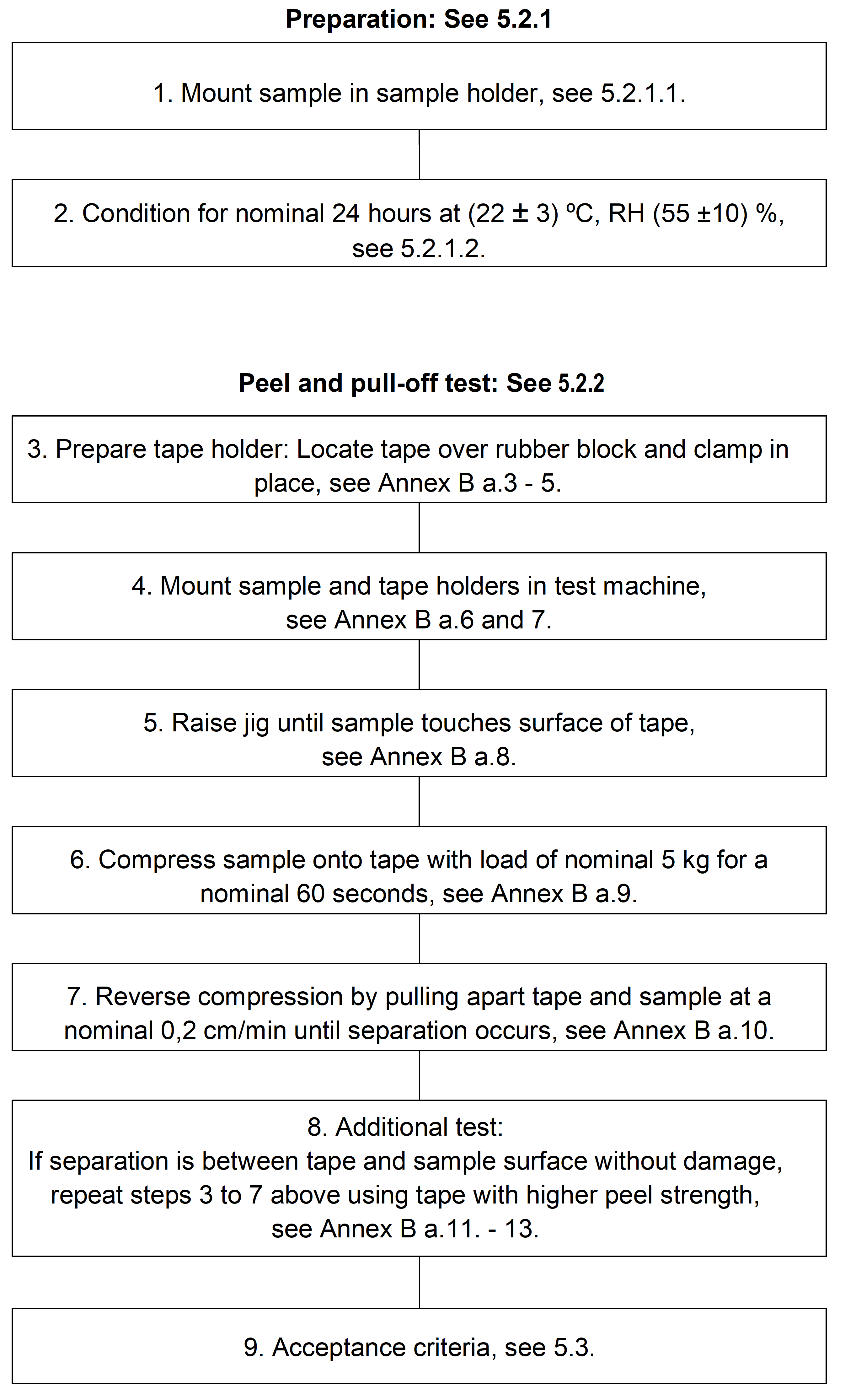 Figure 41 Test procedure flow diagram
Requirements
Preparatory conditions
Hazards, health and safety precautions
The supplier shall identify, manage and process materials and parts with hazardous characteristics according to ECSS–Q-ST-40.
The supplier shall keep the health and safety precautions according to the supplier’s national safety regulations.
Preparation of samples
Configuration
The supplier shall prepare the material samples according to the process specifications or manufacturer’s data.
The material samples shall be representative of batch variance.
If it is not practicable to test completed assemblies, the supplier shall submit samples made from the same materials and by the same processes as those used in the manufacture of the assemblies.
The sample for testing shall have clean flat surfaces which do not overlap the sample holder described in clause 5.1.4.
The width of the test sample surface face shall be at least equal to the width of the tape used in the test procedure.
The nominal tape width shall be 20 mm.
The supplier shall specify the number of samples to be taken from a qualification batch, test programme, or production batch at the start of the test in conformance with the DRD in Annex A..
The supplier shall test at least ten test samples.
If it is not practicable to obtain test samples from the finished article, the supplier shall furnish bonded test samples for the test.
These samples are not used for any other purpose than the designated test.
The supplier shall furnish a certificate of conformity for the purpose of traceability.
This certificate of conformity is delivered by the manufacturer in order to provide evidence that the product is compliant with the manufacturer’s process.
The supplier shall mark all test samples with identification to maintain traceability but in such a way as not to degrade the quality of the sample during testing.
Cleaning
The suppler shall perform the same cleaning and other treatments of the sample as that applied to the finished article, which the sample is intended to represent, prior to integration into the spacecraft.
The supplier shall not carry out further cleaning or other treatments.
Handling and storage
The supplier shall handle the samples only with clean nylon or lintfree gloves.
The supplier shall store the samples in a controlled area, with an ambient temperature of (22 ± 3) °C and relative humidity of (55 ± 10) %.
The supplier shall shield coated surfaces from contact by using polyethylene or polypropylene bags or sheets.
The supplier shall avoid physical damage by packing the polyethylene or polypropylenewrapped workpieces in clean, dust and lintfree material.
The supplier shall label limitedlife materials with their shelf lives and dates of manufacture, or date of delivery if date of manufacture is not known.
Identification
Materials
The supplier shall identify materials submitted for testing in conformance to annex A of ECSS-Q-ST-70-02.
Assemblies
The supplier shall identify assemblies submitted for testing, as a minimum, by:
- trade name and batch number;
- name of manufacturer or supplier through whom the purchase was made;
- configuration control status of the assembly.
Facilities
Cleanliness
The work area shall be clean and free of dust.
The supplier shall filter the air used for ventilation to prevent contamination of the sample.
Sample conditioning
The supplier shall environmentally condition the sample for a nominal 24 hour period at (22 ± 3) °C with a relative humidity of (55 ± 10) %.
- 1 The humidity requirement can be achieved either in a conditioning room, or by dessicators filled with silica gel or a saturated salt solution.
- 2 A saturated salt solution of calcium nitrate gives approximately 51 % relative humidity at the testing temperature.
Equipment
Special equipment
The supplier shall use the equipment as detailed in clauses 5.1.4.2 and 5.1.4.3.
Testing machine
The supplier shall employ a powerdriven machine capable of maintaining a specified constant rate of loading and able to be used for both tensile and compressive testing.
The machine shall have a fixed or essentially stationary member supporting a load cell and the tape holder.
A movable member shall carry the sample holder.
The applied compressive and tensile loads, as measured and recorded, shall be accurate within 1 percent of the load.
The rate of travel of the sample holder shall be at a nominal rate of 0,2 cm/min.
Fixtures
The tape holder should be of a design similar to that depicted in Figure 51.
The part shall be screwed into the fixed member of the testing machine or be located firmly on it.
The supplier shall clamp a length of pressure-sensitive tape from one tape holder over the rubber block to the other tape holder.
The surface of the pressure-sensitive tape in contact with the flat surface of the rubber block shall be 4 cm2 ± 5 %.
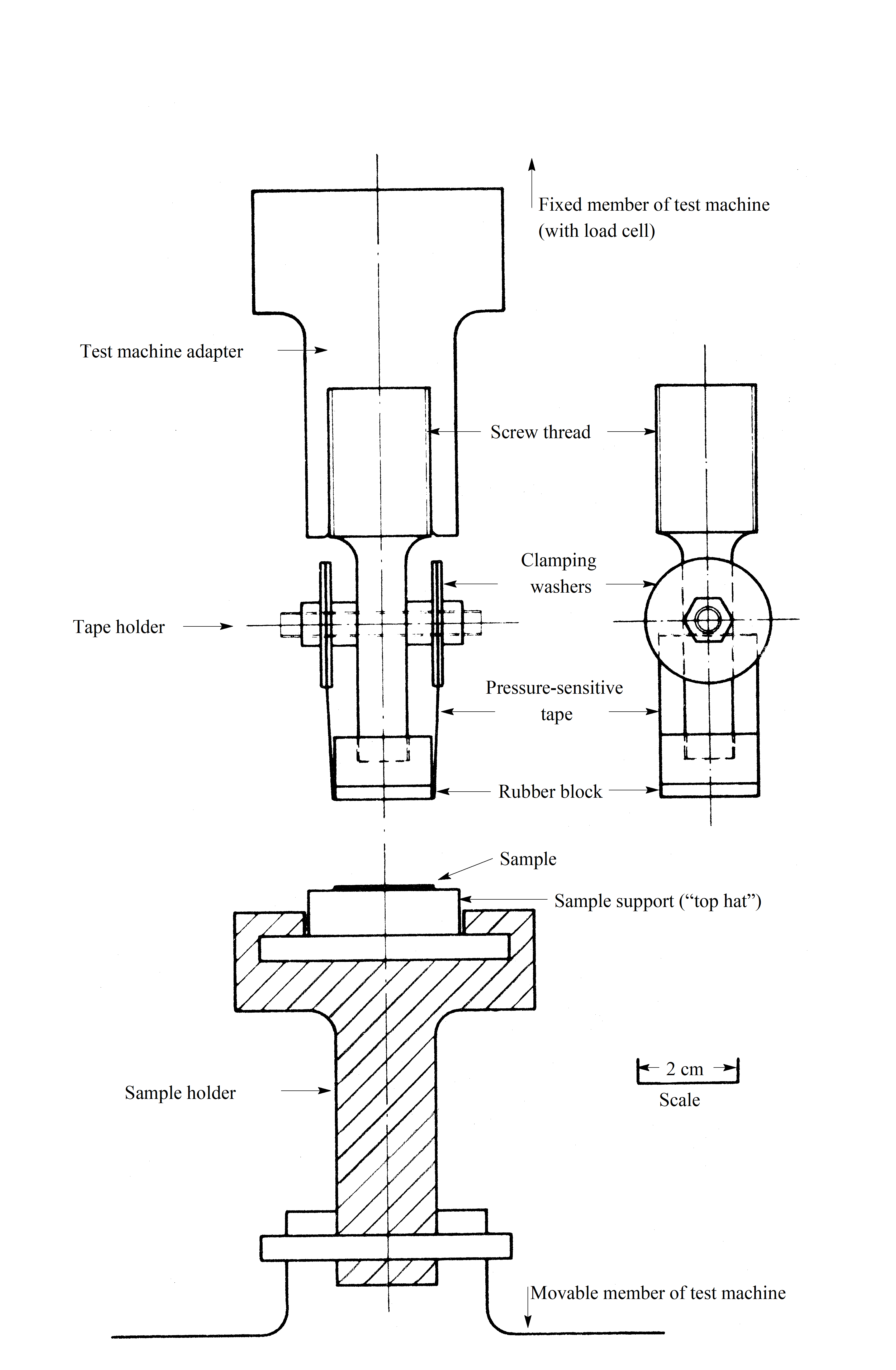 Figure 51: Side view of the test fixtures
Sample holder
The sample holder shall be firmly located beneath the tape holder on the movable member of the testing machine.
- 1 A suitable design is seen in Figure 51.
- 2 This preferred system utilizes “top hat” supports onto which individual samples can be mechanically clamped or bonded in such a way that there is no relative movement between the support and the test sample at any time during the test cycle.
In case a “top hat” sample support is used, it shall slide into a horizontal fixture slot in such a way that its top surface is parallel to and directly beneath the rubber face of the tape holder.
Peel adhesion tape
The supplier shall employ a range of pressuresensitive tapes for the tests with peel adhesion strengths of 220, 330, 440 and 670 g/cm, all with a tolerance of ± 10 %.
Test procedure
Preparation
Mounting
The supplier shall locate the test sample on the sample holder in conformance with the requirements stated in clause 5.1.4.3.
If an adhesive bond is used between the sample and the sample support, this shall in no way interfere with the area under test.
The supplier shall ensure that there is no physical or chemical interaction between any adhesive employed during sample preparation and the sample materials.
Conditioning
The supplier shall condition the loaded sample support for a nominal 24 hours in conformance with the requirements stated in clause 5.1.3.2 before the test starts.
Peel and pulloff test
The supplier should run the peel and pull-off test as described in Annex B.
If the supplier uses a different procedure, the supplier shall submit it for customer approval.
Handling and packaging of tested samples
The supplier shall apply the conditions specified in clause 5.1.2.3 unless other post test disposal instructions are given.
Acceptance criteria
The supplier shall classify samples which have been tested and are not seen to be disturbed in any way by the processing described in clause 5.2.2 as having passed this test.
The supplier shall examine samples in detail, which have been disturbed during the test sequence.
The supplier shall carry out a visual examination for sample defects at ×7 magnification.
In case defects are detected at ×7 magnification, the supplier should use higher magnifications during further analysis for locating microscopic defects on any fracture surfaces.
The supplier shall report defects and the appearance of the fracture.
- 1 Defects for instance can be air bubbles or material inclusions.
- 2 Appearance of the fracture for instance can be rough, ductile, smooth or brittle.
The supplier shall state the particular material or interface along which the fracture path has propagated through the test sample.
This can be wholly or partly an adhesion fracture, a cohesive separation or an adherent fracture as schematically drawn in Figure C-1.
The supplier shall take a photographic record of the tested samples at appropriate level of magnification.
Typical topographical features are recorded at ×2, ×20, ×50, ×100, ×250, ×500 or ×1000 magnifications.
The supplier shall agree with the customer on the granularity level of failure analysis to be performed on failed samples, prior to the test.
The supplier shall perform the failure analysis as agreed with the customer.
This failure analysis can include metallographic studies, chemical analysis or scanning electronic microscopy.
Quality assurance
Data
The supplier shall retain the quality records for at least ten years or in conformance with project business agreement requirements, and in conformance with the Test result sheet - DRD in Annex A.
Example of such quality records are logbooks.
Nonconformance
The supplier shall disposition any nonconformance which is observed in respect of the test process in conformance with the quality assurance requirements specified in ECSS-Q-ST-10-09.
Calibration
The supplier shall use only measuring equipment calibrated to traceable reference standard.
The supplier shall record any suspected or actual equipment failure as a project nonconformance report according to ECSS-Q-ST-20.
This is to ensure that previous results can be examined to ascertain whether or not reinspection and retesting is required.
The supplier shall notify the customer of the nonconformance details.
Traceability
The supplier shall maintain traceability throughout the process from incoming inspection to final test, including details of test equipment and personnel employed in performing the task.
ANNEX(normative)Test result sheet - DRD
DRD identification
Requirement identification and source document
This DRD is called from ECSS-Q-ST-70-13, requirement 5.4.1a.
Purpose and objective
The purpose of the test result sheet is to summarize the test results.
Expected response
Scope and content
The test result sheet shall contain the trade names of the materials under test.
The test result sheet shall contain the batch numbers of the materials under test.
The test result sheet shall contain name of manufacturer or supplier through whom the purchase was made.
The test result sheet shall contain summary of the preparation and conditioning schedule.
This can be for instance the mixing proportions, coating thickness, cure time and temperature, postcure or cleaning procedure.
The test result sheet shall contain details of the testing room environment conditions and test equipment.
The test result sheet shall contain details of the test parameters outlined in Annex B.
This also includes any variation in testing environment conditions.
The test result sheet shall contain details of equipment used for visual, mechanical, chemical and physical property measurement or inspection, as outlined in Annex B and test specifications where they exist.
The test result sheet shall contain the number of sample tests.
The test result sheet shall contain the results of the values obtained for peel or pulloff strength.
The test result sheet shall contain the peel strength indicated by the manufacturer of the pressuresensitive tape used.
The test result sheet shall contain the results of any failure analysis carried out according to clause 5.3.
The test result sheet shall contain the mode of fracture and any photographic records.
An indication of the various fracture line is given in Figure C-1.
In case of failures, the test result sheet shall contain the following details of failure mode:
- deficient design;
- poor workmanship;
- wrong fabrication or application procedure;
- wrong choice of materials;
- others.
Special remarks
The supplier may use the template given in Figure A-1.
|
Materials Section, Product Assurance Division, ESTEC
| ||||
|
Sample details
|
|
|
|
|
|
1. Description and history of sample:
|
|
|
||
|
2. Trade name:
|
|
|
||
|
2. Batch number:
|
|
|
||
|
4. Coating or finish material manufacturer:
|
|
|
||
|
5. Supplier through whom material is purchased:
|
|
|
||
|
6. Coating or finish prepared by:
|
|
|
||
|
7. Summary of preparation schedule:
|
|
|
||
|
8. Number of samples submitted:
|
|
|
||
|
9. Criteria for test, e.g. lowest acceptable peel or pulloff strength:
|
|
|
||
|
10. Project and cost code number:
|
|
|
||
|
Date:
|
Originator:
|
|
Telephone:
|
|
|
Test results
|
|
|
|
|
|
11. Test equipment:
|
|
|
|
|
|
12. Test temperature: °C
|
|
13. Relative humidity: %
| ||
|
14. Speed of testing: cm/min
|
|
|
||
|
15. Sample number
|
16. Peel strength of tape employed *
|
17. Peel or pulloff strength of sample **
|
18. Mode of fracture, see Figure 3
|
19. Further examinations
|
|
Conclusions
|
|
|
|
|
|
Date:
|
Test engineer:
|
|
Approval:
|
|
|
* as indicated by manufacturer, the peel strength of tape when sample separation commenced is underlined.** from chart record |
||||
Figure: Example of test result sheet
ANNEX(informative)Peel and pull-off test procedure
The supplier should perform the peel and pull-off test according to the following procedure:
conduct the test as soon as possible after the loaded sample support has been removed from the conditioning atmosphere;
conduct the test under the same environment conditions;
prepare the tape holder by hand;
fix a length of the lowest peelstrength tape in such a way that it follows the contour of the rubber block without creases, folds, visible surface flaws or slack spots;
secure the two free ends of the tape and stretches the tape so as to leave no slack;
locate the tape holder and sample support holder on the fixed member and the movable member of the machine respectively;
position the sample under test, being bonded onto the sample support, in the support holder in such a way as to be directly beneath the rubber block of the tape holder;
then raise the lower adjustable member of the machine so that the surface of the test sample comes into contact with the pressuresensitive tape;
apply a compressive load of a nominal 5 kg for a nominal 60 s, so as to ensure that the pressuresensitive tape is in positive contact with the sample surface;
move away the movable member of the machine from the test sample at a constant rate of a nominal 0,2 cm/min until such time as there is complete detachment between the tape and the sample;
visually examine the parted surfaces at a magnification of between ×3 and ×7;
With this examination, determine whether separation has occurred cleanly between the tape and the sample surface or whether the surface finish has delaminated from the substrate of the sample;
In the case where separation has occurred cleanly between the tape and the sample surface, remove the tape fixture from the machine and replace the used tape by a new length of tape having a greater peel strength;
recommence the procedure from step 3;
Continue the procedure until either delaminating of the surface finish occurs, or the tape having the maximum peel strength given at clause 5.1.4.5 has been employed.
ANNEX(informative)Fracture lines
Figure C-1 represents an schematic cross-section of a coated substrate showing various fracture lines dependent on the weakest layer.
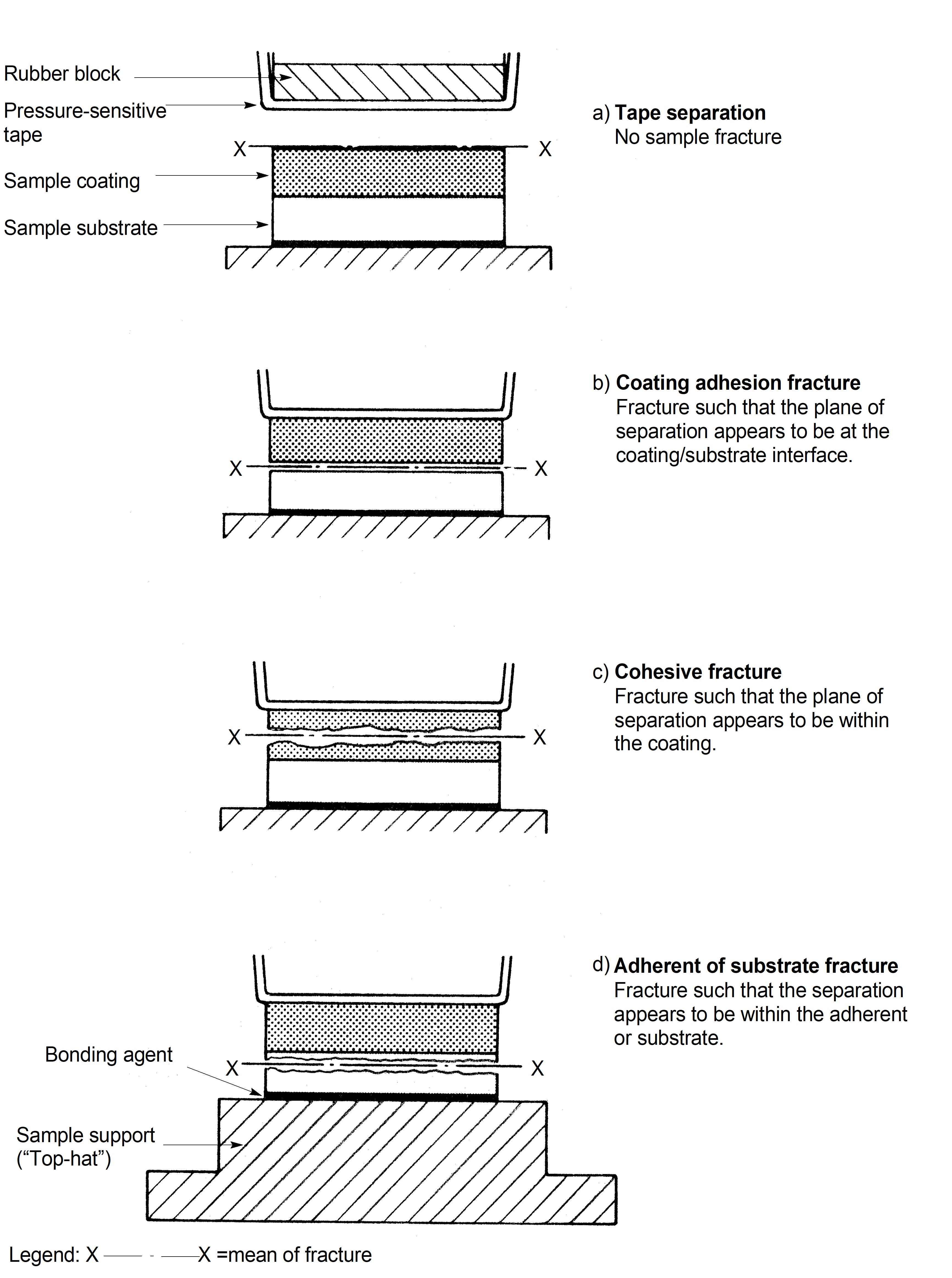 Figure: Schematic cross-section of a coated substrate showing various fracture lines dependent on the weakest layer
Bibliography
|
ECSS-S-ST-00
|
ECSS system – Description, implementation and general requirements
|