
Space engineering
Two-phase heat transport equipment
Foreword
This Standard is one of the series of ECSS Standards intended to be applied together for the management, engineering and product assurance in space projects and applications. ECSS is a cooperative effort of the European Space Agency, national space agencies and European industry associations for the purpose of developing and maintaining common standards. Requirements in this Standard are defined in terms of what shall be accomplished, rather than in terms of how to organize and perform the necessary work. This allows existing organizational structures and methods to be applied where they are effective, and for the structures and methods to evolve as necessary without rewriting the standards.
This Standard has been prepared by the ECSS-E-ST-31-02C Working Group, reviewed by the ECSS Executive Secretariat and approved by the ECSS Technical Authority.
Disclaimer
ECSS does not provide any warranty whatsoever, whether expressed, implied, or statutory, including, but not limited to, any warranty of merchantability or fitness for a particular purpose or any warranty that the contents of the item are error-free. In no respect shall ECSS incur any liability for any damages, including, but not limited to, direct, indirect, special, or consequential damages arising out of, resulting from, or in any way connected to the use of this Standard, whether or not based upon warranty, business agreement, tort, or otherwise; whether or not injury was sustained by persons or property or otherwise; and whether or not loss was sustained from, or arose out of, the results of, the item, or any services that may be provided by ECSS.
Published by: ESA Requirements and Standards Division ESTEC, P.O. Box 299, 2200 AG Noordwijk The NetherlandsCopyright: 2017 by the European Space Agency for the members of ECSS## Change log
|
ECSS-E-ST-31-02C
|
First issue
|
|
ECSS-E-ST-31-02C Rev.1
|
First issue, Revision 1
|
Introduction
This Standard replaces ESA PSS-49, Issue 2 “Heat pipe qualification requirements”, written in 1983, when the need for heat pipes in several ESA projects had been identified. At that time a number of European development activities were initiated to provide qualified heat pipes for these programmes, which culminated in a first heat pipe application on a European spacecraft in 1981 (MARECS, BR-200, ESA Achievements - More Than Thirty Years of Pioneering Space Activity, ESA November 30, 2001), followed by a first major application on a European communication satellite in 1987 (TV-SAT 1, German Communication Satellites).
ESA PSS-49 was published at a time, when knowledge of heat pipe technology started to evolve from work of a few laboratories in Europe (IKE, University Stuttgart, EURATOM Research Centre, Ispra). Several wick designs, material combinations and heat carrier fluids were investigated and many process related issues remained to be solved. From today’s view point the qualification requirements of ESA PSS-49 appear therefore very detailed, exhaustive and in some cases disproportionate in an effort to cover any not yet fully understood phenomena. As examples the specified number of qualification units (14), the number of required thermal cycles (800) and the extensive mechanical testing (50 g constant acceleration, high level sine and random vibration) can be cited.
The present Standard takes advantage of valid requirements of ESA PSS-49, but reflects at the same time today’s advanced knowledge of two-phase cooling technology, which can be found with European manufacturers. This includes experience to select proven material combinations, reliable wick and container designs, to apply well-established manufacturing and testing processes, and develop reliable analysis tools to predict in-orbit performance of flight hardware. The experience is also based on numerous successful two-phase cooling system applications in European spacecraft over the last 20 years.
Besides streamlining the ESA PSS-49, to arrive at today’s accepted set of heat pipe qualification requirements, the following features have also been taken into account:
Extension of PSS-49 heat pipe qualification requirements to include heat pipe acceptance requirements;
Inclusion of qualification and acceptance requirements for two-phase loops (CPL, LHP);
Reference to applicable requirements in other ECSS documents;
Formatting to recent ECSS template in order to produce a document, which can be used in business agreements between customer and supplier.
Scope
This standard defines qualification and acceptance requirements for two-phase heat transportation equipment (TPHTE), for use in spacecraft thermal control.
This standard is applicable to qualification and acceptance activities of new hardware.
However, acceptance requirements of this Standard can be used for existing hardware, which has been qualified previously to other requirements than listed herein.
Requirements for mechanical pump driven loops (MPDL) are not included in the present version of this Standard.
This standard also includes definitions and part of the requirements of ECSS-E-ST-32-02 applicable to TPHTE qualification and acceptance.
This standard may be tailored for the specific characteristics and constraints of a space project in conformance with ECSS-S-ST-00.
Normative references
The following normative documents contain provisions which, through reference in this text, constitute provisions of this ECSS Standard. For dated references, subsequent amendments to, or revision of any of these publications do not apply. However, parties to agreements based on this ECSS Standard are encouraged to investigate the possibility of applying the more recent editions of the normative documents indicated below. For undated references, the latest edition of the publication referred to applies.
|
ECSS-S-ST-00-01
|
ECSS system - Glossary of terms
|
|
ECSS-E-ST-10-02
|
Space engineering - Verification
|
|
ECSS-E-ST-10-03
|
Space engineering - Testing
|
|
ECSS-E-ST-10-06
|
Space engineering - Technical requirements specification
|
|
ECSS-E-ST-31
|
Space engineering - Thermal control general requirements
|
|
ECSS-E-ST-32
|
Space engineering - Structural general requirements
|
|
ECSS-E-ST-32-01
|
Space engineering- Fracture control
|
|
ECSS-E-ST-32-02
|
Space engineering - Structural design and verification of pressurized hardware
|
|
ECSS-Q-ST-70
|
Space product assurance - Materials, mechanical parts and processes
|
|
EN 9100:2009
|
Aerospace series - Quality management systems - Requirements for Aviation, Space and Defense Organizations
|
Terms, definitions and abbreviated terms
Terms defined in other standards
For the purpose of this Standard, the terms and definitions from ECSS-E-ST-00-01 apply, and in particular the following:
acceptance
certification
component
customer
equipment
product assurance
qualification
supplier
For the purpose of this standard, the following terms and definitions from ECSS-E-ST-10-02 apply:
acceptance stage
analysis
inspection
qualification stage
review-of-design (ROD)
test
For the purpose of this standard, the following terms and definitions from ECSS-E-ST-32-02 apply:
burst pressure
internal pressure
leak-before-burst (LBB)
pressure vessel (PV)
pressurized hardware (PH)
proof test
Terms specific to the present standard
capillary driven loop (CDL)
TPL in which fluid circulation is accomplished by capillary action
See TPL definition in 3.2.21.
capillary pumped loop (CPL)
CDL with the fluid reservoir separated from the evaporator and without a capillary link to the evaporator
See CDL definition in 3.2.1.
constant conductance heat pipe (CCHP)
heat pipe with a fixed thermal conductance between evaporator and condenser at a given saturation temperature
See heat pipe definition in 3.2.7.
dry-out
depletion of liquid in the evaporator section at high heat input when the capillary pressure gain becomes lower than the pressure drop in the circulating fluid
effective length
heat pipe length between middle of evaporator and middle of condenser for configurations with one evaporator and one condenser only
Used to determine the heat pipe transport capability (see 3.2.10).
exposure temperature range
maximum temperature range to which a TPHTE is exposed during its product life cycle and which is relevant for thermo-mechanical qualification
-
1 The internal pressure at the maximum temperature of this range defines the MDP for the pressure vessel qualification of a TPHTE.
-
2 The extreme temperatures of this range can be below freezing or above critical temperatures of the working fluid.
-
3 In other technical domains, this temperature range is typically called non-operating temperature range (see clause 4 for additional explanation).
heat pipe (HP)
TPHTE consisting of a single container with liquid and vapour passages arranged in such a way that the two fluid phases move in counter flow -
1 See TPHTE definition in 3.2.20.
-
2 The capillary structure in a heat pipe extends over the entire container length.
heat pipe diode (HPD)
heat pipe which transports heat based on evaporation and condensation only in one direction
See heat pipe definition in 3.2.7.
loop heat pipe (LHP)
CDL with the fluid reservoir as integral part of the evaporator
- 1 See CDL definition in 3.2.1.
- 2 The reservoir can be separated, but has a capillary link to the evaporator.
heat transport capability
maximum amount of heat, which can be transported in a TPHTE from the evaporator to the condenser
For heat pipes it is the maximum heat load expressed in [Wm] (transported heat times effective length).
maximum design pressure (MDP)
maximum allowed pressure inside a TPHTE during product life cycle
mechanical pump driven loop (MPDL)
TPL in which fluid circulation is accomplished by a mechanical pump
See TPL definitions in 3.2.21.
product life cycle
product life starting from the delivery of the TPHTE hardware until end of service live
The product life cycle starts after acceptance of the product for flight.
reflux mode
operational mode where the liquid is returned from the condenser to the evaporator by gravitational forces and not by capillary forces
start-up
operational phase starting with initial supply of heat to the evaporator until nominal operating conditions of the device are established
sub-cooling
temperature difference between average CDL reservoir temperature and the temperature of the liquid line at the inlet to the reservoir
The average CDL reservoir temperature represents the saturation temperature inside the reservoir.
thermal performance temperature range
temperature range for which a TPHTE is thermally qualified
In the thermal performance temperature range a thermal performance map exists.
tilt for HP
height of the evaporator above the condenser during ground testing
- 1 This definition is valid for a configuration with one evaporator and one condenser (see Figure 31).
- 2 The tilt is measured from the highest point to the lowest point in Figure 31.
 Figure 31: Tilt definition for HP
tilt for LHP
height of the evaporator above the reservoir during ground testing
- 1 See Figure 32.
- 2 The tilt is measured from the highest point of the evaporator to the lowest point of the condenser in Figure 32.
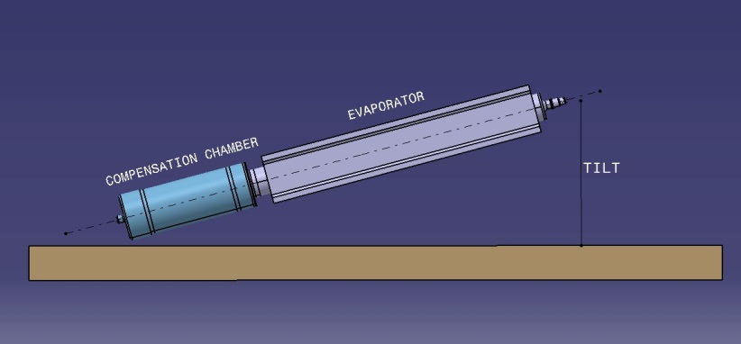 Figure 32: Tilt definition for LHP
two-phase heat transport equipment (TPHTE)
hermetically closed system filled with a working fluid and transporting thermal energy by a continuous evaporation and condensation process using the latent heat of the fluid
- 1 A fluid evaporates in the heat input zone (evaporator) and condenses in the heat output zone (condenser).
- 2 This is in contrast to a single-phase loop where the sensible heat of a liquid is transported (a liquid heats up in the heat input zone and cools down in the heat output zone).
two-phase loop (TPL)
TPHTE with physically separated vapour and liquid transport lines forming a closed loop
See TPHTE definition in 3.2.20.
variable conductance heat pipe (VCHP)
heat pipe with an additional non-condensable gas reservoir allowing a variable thermal conductance between evaporator and condenser
- 1 See heat pipe definition in 3.2.7.
- 2 The variation in thermal conductance is generally accomplished by regulating the volume of a non-condensable gas plug reaching into the condenser zone, which in turn varies the effective condenser length.
- 3 The variation of the gas volume can be performed by active or passive means.
Abbreviated terms
The following abbreviations are defined and used within this standard:
|
Abbreviation
|
Meaning
|
|
CCHP
|
constant conductance heat pipe
|
|
CDL
|
capillary driven loop
|
|
CPL
|
capillary pumped loop
|
|
CTE
|
coefficient of thermal expansion
|
|
DRD
|
document requirements definition
|
|
HP
|
heat pipe
|
|
HPD
|
heat pipe diode
|
|
LBB
|
leak before burst
|
|
LHP
|
loop heat pipe
|
|
MDP
|
maximum design pressure
|
|
MPDL
|
mechanical pump driven loop
|
|
MSPE
|
metallic special pressurized equipment
|
|
NDI
|
non-destructive inspection
|
|
PH
|
pressurized hardware
|
|
ROD
|
review-of-design
|
|
Qmax
|
maximum heat transport capability
|
|
SPE
|
special pressurized equipment
|
|
TCS
|
thermal control (sub)system
|
|
TPHTE
|
two-phase heat transport equipment
|
|
TPL
|
two-phase loop
|
|
TS
|
technical requirement specification
|
|
VCHP
|
variable conductance heat pipe
|
|
VP
|
verification plan
|
Nomenclature
The following nomenclature applies throughout this document:
The word “shall” is used in this Standard to express requirements. All the requirements are expressed with the word “shall”.
The word “should” is used in this Standard to express recommendations. All the recommendations are expressed with the word “should”.
It is expected that, during tailoring, recommendations in this document are either converted into requirements or tailored out.
The words “may” and “need not” are used in this Standard to express positive and negative permissions, respectively. All the positive permissions are expressed with the word “may”. All the negative permissions are expressed with the words “need not”.
The word “can” is used in this Standard to express capabilities or possibilities, and therefore, if not accompanied by one of the previous words, it implies descriptive text.
In ECSS “may” and “can” have completely different meanings: “may” is normative (permission), and “can” is descriptive.
The present and past tenses are used in this Standard to express statements of fact, and therefore they imply descriptive text.
TPHTE verification principles
TPHTE categorization
TPHTE as defined in 3.2.20 of this Standard are considered ‘special pressurized equipment’ (SPE), as per definition of ECSS-E-ST-32-02. Requirements of ECSS-E-ST-32-02 are included in this Standard for this reason.
The TPHTE are categorized in Figure 41 according to their design and functional principle.
HP’s, LHP’s and CPL’s are categorized as MSPE (Metallic Special Pressurized Equipment) as described in section 4.1.2 ECSS‐E‐ST‐32‐02
Heat pipes consist of a single container with a capillary structure extending over the entire container length. Liquid and vapour passages are arranged in such a way that the two fluid phases move in counter flow.
Capillary driven loops (CDL) have separate evaporator and condenser sections, which are connected by dedicated vapour and liquid tubing. At least one capillary structure is located in the evaporator section, which serves as capillary pump to circulate the fluid in a true loop configuration.
The mechanically pumped two-phase loop (MPDL) has a configuration, which is similar to the CDL, except that the circulation of the fluid is accomplished by a mechanical pump.
Requirements for MPDL are not included in the present version of this Standard.
Involved organizations
The verification process of TPHTE is generally carried out by a specialized equipment manufacturer (called in this document “supplier”) and controlled by the verification authority (called in this document the “customer”).
The verification activity is embedded in the supplier’s product assurance and quality organization and in most cases the supplier's quality assurance plan has been established and approved for space activities independently from the TPHTE verification process specified in this document. It is the task of the supplier’s PA authority to introduce and approve adequate product assurance provisions at his subcontractor(s). The existence of an approved PA Plan is precondition for commencing verification activities.
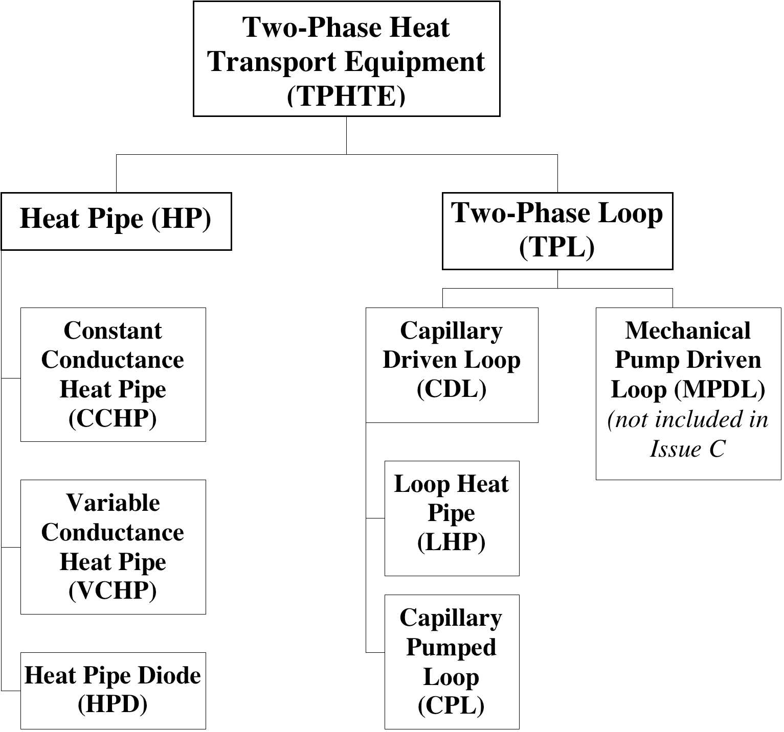 Figure 41: Categories of TPHTE (two-phase heat transport equipment)
Generic requirements in this standard
The present document provides generic, i.e. not project specific requirements for formal verification of TPHTE. It is therefore important to select overall and enveloping verification requirements in order to support a maximum of spacecraft application without the need for delta verification.
TPHTE qualification principles
Processes, number of qualification units
The qualification of TPHTE is based on validated manufacturing processes (e.g. cleaning, surface treatment, welding and leak testing) and covers in general the following areas:
Performance over long operation time (compatibility between fluid and wall material, space radiation, leak tightness)
Mechanical performance (strength, pressurized hardware)
Thermal performance (e.g. heat transport capability, start-up behaviour, heat transfer coefficients)
In this context the number of TPHTE units to be produced for the qualification program are evaluated and selected by the supplier. There are no general applicable sources, which specify the minimum of units to be used to undergo identical qualification testing in order to achieve a successful qualified product. The question to be answered for each TPHTE configuration is: how many identical units need to be built and tested in order to validate the production process.
The following are possible selection criteria:
Experience of the manufacturer in production of similar products,
Simplicity of the configuration,
TPHTE design features, which have inherent capability for good repeatability of the production processes (e.g. simple axial grooved heat pipes).
This Standard specifies the number of needed identical pieces of equipment (i.e. coming from the same batch) submitted to the qualification process.
Compared to full qualification of a new product the number of units can be reduced for delta qualification of an existing but modified product. (see Table 51 for details).
Thermal and mechanical qualification
Temperature range
In contrast to most of electronic equipment, the performance of a TPHTE varies with its operating temperature, because properties of the used heat carrier are temperature dependent. For heat pipes as an example, important fluid properties can be grouped into a figure-of-merit (G), which is the product of surface tension, heat of vaporization and liquid density divided by the liquid viscosity (for more information see references in Bibliography). G is plotted for some fluids over the temperature in Figure 42. The heat transport capability of a capillary pumped loop is proportional to these curves.
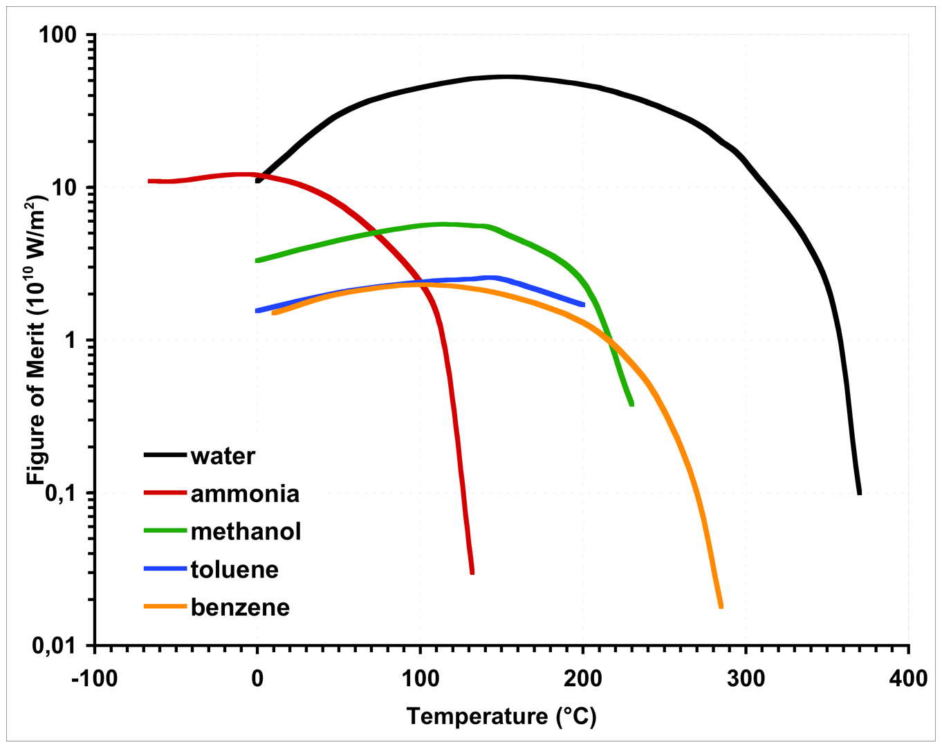 Figure 42: Figure-of-merit (G) for some TPHTE fluids
Generally, the applicable temperature range of a TPHTE is subdivided into a thermally and a mechanically relevant regime.
The thermal performance temperature range, which is used for thermal qualification, is defined within the theoretical operating temperature range, confined by the freezing and the critical temperature of the used fluid. Lower and upper temperature limits of the qualification range are selected in such a way that a useful map of thermal performance data can be established. Within this range the maximum transport capability for qualification is determined. For a specific space application the operating temperature range (within the thermal performance temperature range) and the maximum required heat transport capability are specified.
For thermo-mechanical qualification the temperature range, to which the device is exposed to during the life cycle, is relevant. In most cases this exposure temperature range is wider than the mentioned thermal performance temperature range. The minimum temperature of this range can be below the freezing temperature of the used heat carrier and it is important to take into account possible damage caused by the freezing or thawing effects. The upper exposure temperature can be even above the critical temperature of the heat carrier. This temperature determines in general the maximum internal pressure for design and qualification of the device.
The mentioned temperature ranges and associated heat transport capabilities are illustrated in Figure 43.
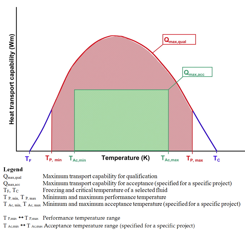 Figure 43: Definition of temperature and performance ranges for a HP
Mechanical qualification
TPHTE are classified as Metallic Special Pressurized Equipment (MSPE) and relevant mechanical requirements are specified in ECSS-ST-E-32-02 and are applied in the present Standard for all TPHTE types.
For qualification of a TPHTE as pressurized component, the main characteristic is the internal pressure, which varies in relation to the exposure temperature of the unit (temperature dependent saturation pressure of the heat carrier liquid).
ECSS-ST-E-32-02 specifies qualification requirements for heat pipes (see figure 4.12 and Table 4-8 of ECSS-E-ST-32-02). The present Standard selects qualification requirements for TPHTE, which have seen proof pressure tests ≥ 1,5 MDP. Testing is the preferred method rather than qualification by fracture control analysis.
For qualifying a TPHTE with respect to external mechanical environment the following mechanical tests are considered:
Constant or static acceleration
Sine vibration
Random vibration
For these tests the qualification unit needs to be rigidly mounted to the test equipment (vibration table). However, such mounting provisions can have only reduced similarity to real applications in spacecraft and the meaningfulness of such tests is, therefore, very often reason for discussion under experts. For heat pipes it is common understanding not to perform these tests on long heat pipe profiles for the following reasons:
The length of the test heat pipe is adapted to the test equipment and is therefore shorter as in many realistic spacecraft applications.
The application of heat pipe is often for embedding them in sandwich structures. Mechanical loads for these applications are quite different as can be simulated with a rigidly fixed single heat pipe profile.
Several capillary structures, in particular axial groove heat pipes, are quite insensitive to mechanical loads and tests as suggested in existing procedures can be unnecessary.
For many TPHTE applications (in particular for devices with simple capillary structures, e.g. axial grooves) the formal mechanical qualification can be therefore performed with the first structural model on satellite level. In case the risk for such a late qualification is high, pre-qualification can be performed on unit or part level in particular for the following cases:
The TPHTE, in particular a heat pipe, has a capillary structure, which is sensitive towards mechanical loads, e.g. arterial wick. In such a case a short piece of the heat pipe profile is selected for mechanical qualification testing (sine, random vibration).
An evaporator of a LHP or CPL can be separately tested (sine, random vibration) to verify that mechanical requirements are met.
Equally this can be true for a two-phase loop condenser, in particular for configurations where the condenser tubing is embedded into a structural panel.
Therefore the Standard does not specify at which model level vibration testing is performed. The supplier and customer are asked to agree on a logical qualification plan, which can include testing at higher than equipment level.
TPHTE acceptance principles
The acceptance process demonstrates that the already qualified product is free of workmanship errors and is ready for subsequent operational use.
Verification is performed by inspection and testing and includes:
Material conformity (for example inspection of certificates, proof pressure, leak check)
Inspection of dimensions and flatness
Thermal performance check
The design of hardware submitted to the acceptance procedure has been previously qualified. However, some application driven design modifications can be accepted as long as the following qualification relevant design features are not compromised:
Material selection and compatibility
Pressurized component
Thermal performance
Some examples are given in Table 41.
It is good practice to perform a similarity analysis to determine that the hardware, submitted to the acceptance process, is of qualified design.
Table 41: Examples of allowed design modifications for acceptance hardware
|
Qualification relevant design feature
|
Mandatory design feature for acceptance hardware
|
Allowed design modification for acceptance hardware
|
|
Material selection and compatibility
|
Wall material and fluid combination;
|
No exception
|
|
Pressurized component
|
Minimum wall thickness and inner diameter of evaporator, fluid lines, condenser;
|
Attachment design (configuration of external flanges);
|
|
Thermal performance
|
Capillary structure
|
Length, number and distribution of evaporator and condenser zones in CCHP
|
Requirements for qualification activity
Technical specification (TS)
General
The qualification process shall be based on a technical specification, approved by the customer.
Usually the technical specification evolves from the functional requirements of the customer and defines the technical performances for the proposed solution as part of a business agreement.
The technical specification specified in 5.1.1a shall be written in accordance with DRD in ECSS-E-ST-10-06 Annex A.
Requirements to the TS
The specification shall be identifiable, referable and related to a TPHTE product.
The following entity shall be responsible for the TS:
- the supplier for a generic TPHTE specification, which is not related to a specific application;
- the customer for a specific TPHTE specification, which is related to a specific application.
A delta qualification can be necessary, if the generic specification does not completely meet the requirements for a specific application.
For technical requirements organization, requirements 7.2.3b to 7.2.3e of ECSS-E-ST-10-06 shall apply.
<<deleted>>
<<deleted>>
<<deleted>>
For technical reference, requirement 7.2.4a of ECSS-E-ST-10-06 shall apply.
For configuration management, requirement 7.2.5a of ECSS-E-ST-10-06 shall apply.
Quantity of units required for the qualification process shall be specified in the TS.
For restriction to requirement specification, requirement 7.2.8a of ECSS-E-ST-10-06 shall apply.
Requirements for formulating technical requirements
For performance specification, requirement 8.2.1a of ECSS-E-ST-10-06 shall apply.
To avoid ambiguity in a specification, requirement 8.2.4a of ECSS-E-ST-10-06 shall apply.
To ensure the uniqueness of a specification, requirement 8.2.5a of ECSS-E-ST-10-06 shall apply.
To ensure the identification of a specification, requirement 8.2.6b of ECSS-E-ST-10-06 shall apply.
To ensure the singularity of a specification, requirement 8.2.7a of ECSS-E-ST-10-06 shall apply
To ensure that a specification is verifiable, requirement 5.1.3f of ECSS-E-ST-10-06 shall apply.
To ensure that a specification includes the tolerance, requirement 5.1.3g of ECSS-E-ST-10-06 shall apply.
For general formatting of requirements in a specification, clause 8.3.1 of ECSS-E-ST-10-06 shall apply.
<<deleted>>
The verbal form for the wording of specification requirements shall be compliant with requirements 8.3.2a to 8.3.2d of ECSS-E-ST-10-06.
<<deleted>>
<<deleted>>
<<deleted>>
The restrictions on the format of specification requirements shall be compliant with clause 8.3.3 of ECSS-E-ST-10-06.
Materials, parts and processes
Materials, parts and processes for TPHTE to be qualified shall be documented in the following lists (see Table 57):
- Declared materials list
- Declared mechanical parts list
- Declared processes list
General qualification requirements
Qualification process
The qualification stage shall be completed before launch.
Supporting infrastructure – Tools and test equipment
Tools to be used to support the qualification process shall be validated for their intended use.
The validation shall be performed under expected environmental conditions and operational constraints.
Compatibility of tools and test equipment interfaces with flight qualification hardware shall be verified by test.
Calibration of laboratory equipment shall be verified prior to their use.
Tools and test equipment that is modified and used in a new application shall be re-verified according to requirements 5.3.2a to 5.3.2d.
Test facilities, tools and instrumentation shall be designed to avoid adverse effects on the qualification objectives.
Examples of these are: Thermocouples, strain gauges, heater mounting, cooling devices, support structures.
Qualification process selection
The scope of the qualification process shall be adapted to the qualification heritage of the product.
For categorization of the heritage the product categories of Table 51 shall be used.
The qualification process shall be structured according to Figure 51.
Table 51: Categories of two-phase heat transport equipment according to heritage (adapted from ECSS-E-ST-10-02C, Table 5-1)
|
Category
|
Description
|
Qualification programme
|
Remarks related to the present Standard
|
|
A
|
Off-the-shelf product without modifications and
|
None
|
|
|
B
|
Off-the-shelf product without modifications.
|
Delta qualification programme, decided on a case-by-case basis in agreement between the customer and the supplier
|
This category relates for example to TPHTE hardware, which is identical to already qualified hardware but has been qualified to lower mechanical loads or narrower operating temperature ranges as required by an actual project.
|
|
C
|
Off-the-shelf product with design modifications
|
Delta or full qualification programme, decided on a case-by-case basis depending on the impact of the modification in agreement between the customer and the supplier
|
Examples for category C are:
|
|
D
|
New designed and developed product.
|
Full qualification programme.
|
Applicable for any new developed TPHTE, including existing systems with new capillary structures or material combinations.
|
Figure 51: Selection of qualification process
Qualification stage
Qualification requirements
<<deleted>>
When a requirement is verified by qualification at lower level, the traceability to the lower level verification evidence shall be provided.
- 1 This concerns manufacturing processes as well as parts, materials and sub-units of a TPHTE.
- 2 Qualification is aimed at demonstrating that the design of the TPHTE meets the requirements of the technical specification. The qualification can be supported by in-orbit demonstration to verify requirements, which are affected by zero-g environment.
Formal close-out of qualification at lower level shall be performed prior to close-out at higher level.
Quality audits
The supplier shall allow quality audits in support to the qualification process in accordance with EN 9100-2009.
Quality audits shall be conducted such that the supplier’s know-how and proprietary data are protected.
As a general rule, audits are performed by quality assurance personnel of the customer and not by experts in the field.
Qualification methods
Overview
A verification plan (VP) shall be prepared in conformance with the DRD in ECSS-E-ST-10-02 Annex A and agreed with the customer.
The qualification of TPHTE shall be accomplished by one or more of the following verification methods:
- Test as specified in 5.5.3.2.
- Analysis, as specified in 5.5.3.3.
- Review-of-design, as specified in 5.5.3.4.
- Inspection, as specified in 5.5.3.5.
Test includes demonstration. Analysis includes similarity.
The verification plan shall define the qualification methods.
Test
Verification by test shall be compliant with requirement 5.2.2.2a of ECSS-E-ST-10-02.
For the verification of safety critical functions clause 8.4.1 of ECSS-Q-ST-40 shall apply.
Qualification shall be carried out on hardware representative of the end item in terms of design, materials, tooling and methods.
TPHTE subject to qualification test shall be manufactured applying validated processes.
Analysis
General
Verification by analysis shall be in accordance with 5.2.2.3 of ECSS-E-ST-10-02.
Analysis shall be performed to predict specified performance parameter of the TPHTE.
Analytical prediction results shall be correlated with qualification test results.
Result correlations lead to software tool validation, which can reduce follow-on qualification processes.
Discrepancies between analytical prediction and test results shall be analysed in order to demonstrate that the objective of the qualification is not compromised.
Mechanical performance analysis and test prediction shall be documented in conformance with Annex J and Annex Q of ECSS-E-ST-32.
Analysis and test prediction can be split in two documents.
Thermal performance analysis and test prediction shall be documented in conformance with Annex C of ECSS-E-ST-31.
Analysis and test prediction can be split in two documents.
Similarity
<<deleted and moved into requirement 5.5.3.3.1a>>
<<deleted and moved into requirement 5.5.3.3.1a>>
Review-of-design (ROD)
Verification by ROD shall be in accordance with 5.2.2.4 of ECSS-E-ST-10-02.
Verification by ROD shall be documented in a Review-of-Design report in conformance with the DRD in ECSS-E-ST-10-02 Annex D.
Inspection
Verification by Inspection shall be in accordance with 5.2.2.5 of ECSS-E-ST-10-02.
Verification by inspection shall be documented in an Inspection Report in conformance with the DRD in ECSS-E-ST-10-02 Annex E.
Full and delta qualification programme
Full qualification programme
Equipment for which a full qualification programme is required as per Table 51 shall be qualified by test according to clause 5.5.3.2 and 5.6 and by analysis according to clause 5.5.3.3.
Delta qualification programme
Equipment for which a delta qualification programme is required as per Table 51 shall undergo a delta qualification programme, which is a subset of the full qualification programme of clause 5.5.4.1.
The delta qualification programme shall be selected on a case-by-case basis and based on the modifications to existing qualified hardware.
The delta qualification programme shall be agreed with the customer.
Performance requirements
Generic requirements
The following generic performance characteristics of a TPHTE shall be determined and verified against specified data:
- Ability to sustain the combination of the predicted worst mechanical loads:
- External mechanical loads.
- Internal loads due to the saturation pressure of the heat carrier fluid within the TPHTE exposure temperature range.
- Thermo-mechanical loads due to temperature cycling and CTE mismatch within the TPHTE exposure temperature range.
- Loads imposed by volume change due to freezing/thawing of the heat carrier within the TPHTE exposure temperature range.
- Safe life item and fatigue-life demonstration
- Safe life item demonstration, performed by analysis or test or both in conformance with ECSS-E-ST-32-01 for TPHTE not submitted to a proof pressure or for which the proof factor used in the proof pressure test is less than 1,5.
- Fatigue-life demonstration, performed by analysis or test or both in conformance with ECSS-E-ST-32 for TPHTE for which the proof factor used in the proof pressure test is equal or larger than 1,5.
- Thermal parameters:
- Minimum and maximum heat transport capability over the TPHTE thermal performance temperature range.
- Evaporator heat flux over the TPHTE thermal performance temperature range.
- Heat transfer coefficient in the evaporator and condenser.
- Overall thermal resistance of the device.
- Operational characteristics
- Maximum heat load applied in one step at discrete temperatures over the specified range.
- Start-up behaviour from frozen conditions, if the exposure temperature range includes freezing of the working fluid.
- For cryogenic TPHTE, start-up from the super-critical state of the working fluid.
- Leak-before-burst.
- Lifetime performance:
- Long-term compatibility between fluid and wetted materials (materials in contact with the fluid).
- Space radiation effects in order to demonstrate that fluid de-composition does not adversely affect specified TPHTE performance during the product life cycle.
To item 3.(a): For heat pipes only the maximum heat transport capability is of interest.
Specific requirements
For CCHP the following specific performance characteristics shall be determined and verified against specified data:
- Reduction of transport capability due to heat pipe bending at the minimum specified radius.
- Reduction of transport capability due to tilt (see Figure 31).
To item 1: The minimum bending radius is defined by the supplier.
For VCHP, the following specific performance characteristics shall be determined and verified against specified data:
- The characteristics specified in 5.5.5.2a,
- Maximum transport capability in fully-on conditions,
- Heat leak from condenser to evaporator in off-mode,
- Thermal resistance between condenser and reservoir,
- Ability to regulate the evaporator temperature with passive and active methods.
Passive methods include devices with non-heated gas reservoirs, active methods include devices with heated/cooled gas reservoirs.
For HP Diode, the following specific performance characteristics shall be determined and verified against specified data.
- The characteristics specified in 5.5.5.2a,
- Maximum heat transport capability in forward mode,
- Time and energy to move from forward to reverse mode,
- Time and energy to move from reverse to forward mode,
- Heat leak from condenser to evaporator in reverse mode. For CDL, the following specific performance characteristics shall be determined and verified against specified data
- Minimum heat load applied under which start-up is possible over the specified temperature range,
- Sensitivity of the minimum heat load in relation to the thermal mass attached to the evaporator,
- Minimum heat load applied under which nominal operation is possible over the specified temperature range,
- Sub-cooling conditions to guarantee specified performance,
- Impact on performance due to tilt and adverse elevation,
- Heat leak from condenser to evaporator in off-mode,
- Ability to regulate the evaporator temperature with passive and active methods.
- 1 Passive methods include devices with passive regulation (by-pass) valves in TPL. Active methods include devices with heated/cooled liquid reservoirs, heated regulation valves and TPLs with thermo-electric cooler (TEC) on the liquid reservoir.
- 2 For 5.5.5.2d.5, a tilt is depicted in Figure 32: adverse elevation means that the evaporator is above the condenser.
Qualification test programme
Number of qualification units
The number of TPHTE units submitted to the qualification programme test units shall be in accordance with Figure 52 and Figure 53.
Test sequence
Equipment for which a full qualification programme is required as per Table 51 shall be verified by qualification testing according to the test sequence as defined in Figure 52 for HP and Figure 53 for CDL.
For an equipment where a delta qualification programme is required as per Table 51, the supplier shall derive from the test sequence of Figure 52 for HP and Figure 53 for CDL a reduced test sequence for delta qualification.
The delta qualification sequence shall be agreed with the customer.
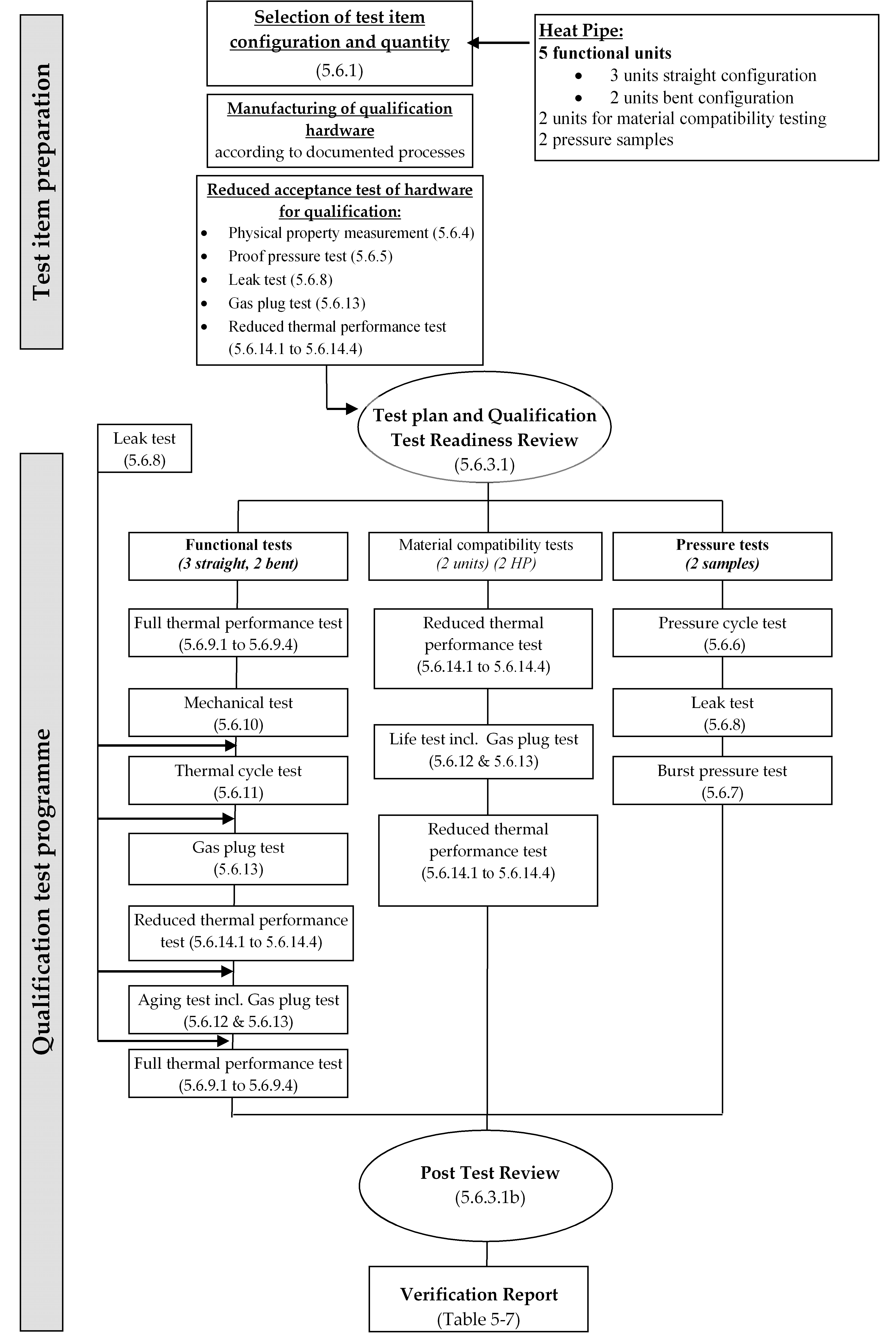 Figure 52: Qualification test sequence for HP
 Figure 53: Qualification test sequence for CDL
Test requirements
Test specification and reviews
Before starting the qualification test campaign the following preconditions shall be met:
- Establishing of a test specification in conformance with the DRD in ECSS-E-ST-10-03 Annex B,
- Establishing of test procedures in conformance with the DRD in ECSS-E-ST-10-03 Annex C, and
- Conductance of test readiness review.
At completion of the test sequence a post-test review shall be conducted.
Test documentation shall be agreed with the customer.
Test conditions
Test tolerances
The test tolerances specified in Table 52 shall be applied to the nominal test values specified.
For the purpose of 5.6.3.2.1a, test tolerances shall include test instrumentation accuracy.
The tolerances specified in Table 52 are the allowable ranges within which the test parameters can vary. The values in the table are inclusive of instrumentation accuracy.
Table 52: Allowable tolerances
|
Test parameters
|
Tolerances
|
|
1. Temperature
|
Low High
|
|
above +100 C
|


|
|
-73 C T +100 C
|


|
|
-100 K (-173 °C) < T ≤ 200 K (-73 C)
|
± 2 K (2 °C)
|
|
40 K (-233 °C) < T ≤ 100 K (-173 C)
|
± 1 K (1 °C)
|
|
10 K (-263 °C) ≤ T ≤ 40 K (-233 C)
|
< 0,5 K (0,5 °C)
|
|
T< 10 K (-263 C)
|
Tolerance to be defined case by case
|
|
2. Relative humidity
|
± 10 %
|
|
3. Pressure (in vacuum chamber)
|
|
|
> 1,3 hPa
|
± 15 %
|
|
1,3 10-3 hPa to 1,3 hPa
|
± 30 %
|
|
< 1,3 10-3 hPa
|
± 80 %
|
|
4. Acceleration
|
-0 / +10 %
|
|
5. Static Load
|
-0 / +10 %
|
|
6. Sinusoidal vibration
|
|
|
Frequency (20 Hz to 2000 Hz)
|
± 2 %
|
|
Amplitude
|
± 10 %
|
|
Sweep rate (Oct/min)
|
± 5 %
|
|
7. Random vibration
|
|
|
Frequency
|
± 5 % (or 1 Hz whichever is greater)
|
|
Amplitude (PSD)
|
|
|
20 Hz - 100 Hz (max control bandwidth 10 Hz)
|
-1/ +3 dB
|
|
100 Hz - 1000 Hz (10 % of midband frequency)
|
-1/ +3 dB
|
|
1000 Hz - 2000 Hz (max control bandwidth 100 Hz)
|
± 3,0 dB
|
|
Random overall g r.m.s.
|
± 10%
|
|
8. Acoustic noise
|
|
|
Sound pressure level, Octave band centre (Hz)
|
Test tolerances (dB)
|
|
31,5
|
-2/+4
|
|
63
|
-1/+3
|
|
125
|
-1/+3
|
|
250
|
-1/+3
|
|
500
|
-1/+3
|
|
1000
|
-1/+3
|
|
2000
|
-1/+3
|
|
Overall
|
-1/+3
|
|
9. Microvibration susceptibility
|
|
|
Quasi-static force or torque
|
± 5 % To be related to the external forces that are applied to extrapolate the transfer functions
|
|
Dynamic forces
|
±10 % To be related to the external forces that are applied to extrapolate the transfer functions
|
|
Sound-power (1/3 octave band centre frequency)
|
|
|
32,5 Hz - 160 Hz
|
±3 dB
|
|
160 Hz – 10000 Hz
|
±2 dB
|
|
10. Shock
|
|
|
Response spectrum amplitude (1/12 octave centre frequency)
|
|
|
Shock level
|
|
|
3000 Hz
|
- 3, + 6 dB
|
|
3000 Hz
|
- 3, + 9 dB
|
|
Shock duration
|
|
|
20 ms
|
0/+ 20 %
|
|
> 20 ms
|
0/+ 10 %
|
|
11. Solar flux
|
|
|
in reference plane
|
± 4 % of the set value
|
|
In reference volume
|
± 6 % of the set value
|
|
12. Infrared flux
|
|
|
Mean value
|
± 3 % on reference plane(s)
|
|
13. Test time
|
-0/+10 %
|
Measurement accuracy
The accuracy of test instrumentation shall be verified in accordance with approved calibration procedures.
All test instrumentation shall be within the normal calibration period at the time of the test.
Table 53: Measurement accuracy
|
Test parameters
|
Accuracy
|
|
1. Mass
|
± 0,1 %
|
|
2. Centre of gravity (CoG)
|
Within a 1 mm radius sphere
|
|
3. Moment of inertia (MoI)
|
± 3 %
|
|
4. Leak rate
|
± 10-5 Pa m3 s-1 of Helium at 1013 hPa pressure differential or at least a factor of two with respect to the leak rate to be measured.
|
Test results
Test results shall be monitored and compared across major test sequences for trends or evidence of anomalous behaviour of the test set up.
Test reports shall be established for each test performed in conformance with the DRD in ECSS-E-ST-10-02 Annex C.
Test data management
Performance test, leak test and long duration test results shall be used to perform trend analysis to detect long-term gradually increasing defects and failures.
Physical properties measurement
The following properties of the test unit shall be measured, recorded and compared to specification in relevant drawings:
- Completeness of configuration,
- Materials as specified,
- Dimension of unit and interfaces,
- Mass,
- Flatness of heat input and heat output zones,
- Fluid amount from manufacturing records,
- Centre of gravity,
- Momentum of inertia.
The determination of centre of gravity and moment of inertia can be performed by analysis.
For the physical properties measurement the test unit shall not include test specific items.
Proof pressure test
Proof pressure test shall be performed applying 1,5 times MDP as specified in ECSS-E-ST-32-02 for duration of 15 minutes.
During manufacturing processes (e.g. curing of panels with embedded heat pipes) the pressure can be higher than MDP, as long as the unit material stays in the elastic domain.
Pressure shall be generated on the sealed unit by increasing the temperature of the unit and thus the saturation pressure of the heat carrier fluid.
- 1 This test is called hot proof pressure test.
- 2 When the pressure target leads to a temperature higher than the critical temperature then the cold pressure test (before unit sealing) can be considered to reach the proof pressure requirement and a reduced proof factor can be accepted for the hot pressure test on the sealed unit.
In cases where proof pressure test is not feasible, margins against mechanical failure shall be verified by analysis in accordance with ECSS-E-ST-32-02.
Pressure cycle test
The pressure cycle test shall consist of 2000 cycles between 1 bar and MDP at ambient temperature.
The supplier shall analyse the number of cycles above the 2000 cycles, to which the TPHTE can be exposed before reaching the Woehler curve.
Burst pressure test
Burst pressure test shall be performed applying 2,5 times MDP for duration of 15 minutes.
No rupture or leak shall occur during burst pressure test.
Burst pressure test shall be carried out with burst pressure samples manufactured from the same material batch and according to processes, which are identical to the ones used for the functional qualification unit.
Burst pressure samples shall include all features of the flight configuration.
For example representative bends, welds and joints.
Burst pressure test shall be performed at the maximum exposure temperature by increasing the internal pressure until the required burst pressure is reached.
Burst pressure testing at lower temperatures can be performed, when a factor corresponding to differences in material properties between test and maximum exposure temperature is taken into account.
After the 15 minutes hold-time, the pressure shall be further increased until rupture occurs and the pressure at rupture shall be recorded.
If burst pressure tests are performed at sub-unit level, the burst pressure test processes shall include all parts of the product including all joints, welds, end fittings.
For example, if it is performed at the level of the evaporator or reservoir of a TPL.
Leak test
Leak test shall be performed at ambient temperature using a detection method agreed with the customer.
The maximum leak rates versus pressure values shall be established through a detailed analysis such that operation of the system is ensured throughout the specified lifetime.
Leak rate of all TPHTE hardware shall conform to the level defined in 5.6.8b.
Pressurized hardware containing hazardous fluids reach end of safe-life when leakage occurs.
During the leak test, the pressure level shall be maintained for 30 minutes as a minimum.
Thermal performance test
General
Thermal performance test results, obtained under 1-g conditions, shall be correlated to predicted in-orbit performance.
For thermal performance tests at ambient conditions, it shall be demonstrated that the conditions specified in 5.6.9.1a do not have an influence on in-orbit performance.
For a specific application the customer can require a thermal performance test in vacuum.
During ground test the unit shall be insulated and the remaining heat exchange with the environment shall be determined.
When establishing the maximum heat transport capability, the vapour temperature shall be varied in increments within the specified operational temperature range such that a performance over temperature curve is generated.
For each temperature step, the temperatures along the length of the unit shall be measured and recorded.
Maximum performance shall be declared, when temperature excursions in the evaporator indicate the beginning of a non-nominal operational condition.
Temperature excursions are generally caused by dry-out conditions in the evaporator.
Temperature readings during performance testing in combination with the applied heat load, corrected for heat exchange with the environment, shall be used to determine heat transfer coefficients in the evaporator and the condenser.
Performance shall be measured as function of the orientation of evaporator versus condenser in the gravitational field.
Test evaluation and data correlation shall be performed for each test and documented in a TCS analysis report in conformance with the DRD in Annex C of ECSS-E-ST-31.
Specific tests for CCHP
Maximum heat transport capability
Maximum heat transport capability shall be measured with
- Straight HP.
- Bent HP.
- Uniform heat input and output.
- One-sided heat input and one-sided heat output, as follows:
- combination of heat input on top of the HP and heat output on bottom of the HP (with respect to gravity),
- combination of heat input on bottom of the HP and heat output on top of the HP (with respect to gravity), and
- side heat input and opposite side heat output.
The supplier shall define performance degradation at the minimum allowed bending radius.
Performance under tilt
The maximum heat transport capability shall be measured for tilt heights from zero to a value at which the heat transport capability falls to a value <5 % of the maximum heat transport capability (at the test temperature).
Measurement shall be performed at sufficient tilt intervals as to create a smooth curve of performance over tilt height.
Test results at different tilt heights shall be extrapolated to zero tilt.
The graphical extrapolation of tilt performance to zero tilt (horizontal position) is assumed to be the zero-g (in-orbit) performance.
Start-up test
A start-up test at the minimum thermal performance temperature by applying 50 % of the maximum heat load specified at that temperature shall be performed and the time until nominal operation shall be determined.
Start-up procedure
After a full depriming (emptying the capillary structure), a start-up procedure shall be determined.
Performance in reflux mode
The heat transfer coefficients in the evaporator and condenser areas shall be derived as a function of power input and temperature.
Test shall be performed by applying power at to the bottom of the liquid pool and measuring the temperature profile along the pipe.
Specific tests for VCHP
For VCHP, the following tests shall be performed:
- The tests specified in clause 5.6.9.2.1 to 5.6.9.2.4.
- Aging tests before charging the device with the control gas.
- Maximum heat transport capability with the gas front located between condenser and reservoir.
- Residual conductance with the gas front between condenser and evaporator.
Specific tests for HP Diode
For HP Diode, the following tests shall be performed:
- The tests specified in clause 5.6.9.2.1 to 5.6.9.2.4.
- A test to determine the time-to-shutdown of the HP Diode, according to the following sequence:
- apply pre-defined heat loads to the nominal condenser;
- vary the vapour temperature in suitable increments within the specified operational temperature range in order to generate a smooth performance over temperature curve;
- ensure that the pre-defined heat loads are 10 %, 30 %, 50 % and 80 % of the derived Qmax in nominal mode for the specific heat pipe profile;
- derive the energy needed for shutdown for each of the above tests.
- A test to determine the time to start-up the heat pipe diode, according to the following sequence:
- apply pre-defined heat loads to the nominal evaporator;
- ensure that the pre-defined heat loads are 10 %, 30 %, 50 % and 80 % of the derived Qmax in nominal mode for the specific heat pipe profile.
Specific tests for CDL
Start-up with low power shall be verified by testing with and without thermal inertia on the evaporator heater system.
The specified performance of a CDL shall be verified under the following test conditions:
- Simulation of large heat load variations (increase and decrease of heat load).
- Simulation of large condenser temperature variations.
- Different orientations with respect to gravity including tilt for LHP.
- Different parasitic heat inputs in the liquid line and into the reservoir.
For 5.6.9.5b.3: for the tilt definition see also Figure 32.
Mechanical tests
General
Sinusoidal, random vibration and shock tests shall be performed on higher than unit level, if the supplier in agreement with the customer demonstrates that tests at unit level produce unrealistic results.
Tests are generally not meaningful for long heat pipes which are later embedded in structural panels and for CDL, for which the configuration in the intended application cannot be represented on unit level (for example: large distance between evaporator and condenser).
Sinusoidal, random vibration and shock tests shall be performed on component level in order to verify critical details of the device.
- 1 Examples are: evaporator and condenser of a LHP, reservoir.
- 2 A deflection test to replace sinusoidal and random testing can be agreed with the customer. For example: TPHTE with capillary structures, which have an inherent characteristic to be damaged by mechanical loads.
Sinusoidal and random vibration tests shall be performed for the three orthogonal axes of the device.
Sinusoidal and random vibration tests shall be performed at the maximum internal pressure, which the device is exposed to during ascent.
A resonance search shall be performed before and after the sinusoidal and random vibration test to determine resonance frequencies, as specified in Table 54.
If meaningful and agreed with the customer constant acceleration and acoustic tests shall be performed.
Table 54: Equipment resonance search test levels
|
Frequency (Hz)
|
Level
|
Sweep rate
|
|
5 to 2 000
|
0,5 g
|
2 octave per min
|
Sinusoidal vibration
The test levels and duration for the sinusoidal vibration test, for generic equipment qualification, independent of the launcher or space element, shall be as specified in Table 55.
Table 55: Sinusoidal vibration qualification test levels
|
Frequency (Hz)
|
Level
|
First frequency > 100 Hz
|
First frequency 100 Hz
|
|
5 to 21
|
11 mm (0 to peak)
|
No notching
|
With notching
|
|
21 to 60
|
20 g (0 to peak)
|
No notching
|
With notching
|
|
60-100
|
6 g (0 to peak)
|
No notching
|
With notching
|
Random vibration
The test levels and duration for the random vibration test, for generic equipment qualification, independent of the launcher or space element, shall be as specified in Table 56.
Table 56: Random vibration qualification test levels
|
Location
|
Duration
|
Levels
| |
|
Equipment located on external panela or with unknown location
|
Verticalb
|
(20 - 100) Hz
|
+3 dB/octave
|
|
|
Lateralb
|
(20 - 100) Hz
|
+3 dB/octave
|
|
Equipment not located on external panela
|
All axes
|
(20 - 100) Hz
|
+3 dB/octave
|
|
a Panel directly excited by payload acoustic environment.
| |||
Thermal cycle test
The thermal cycle test shall consist of 8 full cycles over the exposure temperature range with a hold-time of 1 hour.
Cycle tests of TPHTE can be performed under ambient conditions.
Aging and life tests
TPHTE shall be operated in a long duration life test as specified in 5.6.12b in order to confirm the specified performance over the product life cycle.
Heat pipes are typically operated in reflux mode.
For qualification purpose of the device the duration of the life test shall be ≥ 8000 hours.
It is advisable that the life test is extended beyond the formal qualification programme.
Aging tests shall be performed in the functional test sequence as given in Figure 52 with a duration of 300 hours.
Life and aging tests shall be performed at the maximum specified operation temperature.
The amount of produced non-condensable gas shall be determined according to 5.6.13 in periodic intervals agreed with the customer, with shorter intervals especially at the beginning for the life test.
Trend analyse according to 5.6.3.3 shall be performed in order to determine the non-condensable gas content at the end of the product life cycle.
The TPHTE supplier shall demonstrate that the non-condensable gas content expected at end of product life cycle does not violate the specified performance.
Gas plug test
The gas plug test shall be performed under the following conditions:
- Heat pipe mounted in reflux mode.
- Condenser is instrumented with temperature sensors in short axial distances.
- Periodic check of axial temperature profile of the condenser end at lowest operating temperature.
For 5.6.13a.1, this means that the orientation is vertical with evaporator at the lower end.
The non-condensable gas content shall be determined based on the measured temperature profile.
It shall be verified that non-condensable gas generation over the lifetime meets the specification for lifetime performance.
Reduced thermal performance test
General
The reduced thermal performance test shall include the general tests specified in 5.6.9.1.
Specific CCHP
CCHP shall be tested according to requirements 5.6.9.2.1a.1, 5.6.9.2.1a.2, 5.6.9.2.1a.3 and 5.6.9.2.1a.4 for one selected configuration [(a), (b) or (c)].
For CCHP, the maximum heat transport capability shall be measured for one tilt between 2,5 mm and 4 mm at two temperatures to be agreed with the customer.
Specific VCHP
For VCHP, the following test shall be performed:
- the test specified in 5.6.14.1 and 5.6.14.2;
- Thermal performance at fully on condition.
Specific HP diode
For HP diode, tests shall be performed as specified in clause to 5.6.9.4 at one vapour temperature and with a heat load of 50 % of Qmax.
The test specified in 5.6.14.4a should be performed at 20 °C.
Specific CDL
Start-up with low and maximum power shall be verified for one condenser sink temperature and by simulation of flight-representative thermal inertia on the evaporator heater system.
Operating procedures
Operating procedures shall be established for all TPHTE hardware.
The procedures specified in 5.7a shall be compatible with the safety requirements and personnel control requirements at the facility where the operations are conducted.
Step-by-step instructions shall be written with such a detail to unambiguously describe the operation.
Storage
When TPHTE hardware is put into storage they shall be protected against:
- exposure to adverse environments that can cause corrosion or degrade the material;
- mechanical damages. When TPHTE hardware is put into storage, induced stresses due to storage fixture constraints shall be avoided by storage fixture design.
Documentation
Documentation summary
Table 57 presents a summary of all documents required by the present standard.
Specific documentation requirements
The following documents shall be written and agreed with the customer before starting the qualification process.
- technical requirements specification (TS);
- verification plan (VP). Test procedures shall be produced for each test performed.
Several procedures can be grouped in one document.
Test reports shall be produced for each test performed.
Several reports can be grouped in one document.
The design and manufacturing file of the qualification hardware shall be under configuration control and available for customer review.
The final outcome of the qualification process shall be documented in the verification report (VRPT) in conformance with the DRD in ECSS-E-ST-10-02 Annex F, and agreed with the customer.
A customer statement on the successful completion of the qualification process is recommended.
Table 57: TPHTE documentation
|
Title of DRD
|
DRD reference
|
Calling requirement in this standard and remarks
|
|
Technical requirements specification
|
ECSS-E-ST-10-06 Annex A
|
Requirement 5.1.1b
|
|
Verification plan
|
ECSS-E-ST-10-02 Annex A
|
Requirement 5.5.3.1a
|
|
Review-of-design report
|
ECSS-E-ST-10-02 Annex D
|
Requirement 5.5.3.4b
|
|
Inspection report
|
ECSS-E-ST-10-02 Annex E
|
Requirement 5.5.3.5b
|
|
Declared materials list
|
ECSS-Q-ST-70, Annex B
|
Requirement 5.2a.1
|
|
Declared mechanical parts list
|
ECSS-Q-ST-70, Annex C
|
Requirement 5.2a.2
|
|
Declared processes list
|
ECSS-Q-ST-70, Annex D
|
Requirement 5.2a.3
|
|
Mechanical and thermal performance analysis and test prediction report
|
ECSS-E-ST-31, Annex C
|
Requirement 5.5.3.3.1e
|
|
Test specification
|
ECSS-E-ST-10-03 Annex B
|
Requirement 5.6.3.1a.1.
|
|
Test procedure
|
ECSS-E-ST-10-03 Annex C
|
Requirement 5.6.3.1a.2.
|
|
Test report
|
ECSS-E-ST-10-02 Annex C
|
Requirement 5.6.3.2.3b.
|
|
Test evaluation and data correlation report
|
ECSS-E-ST-31, Annex C
|
Requirement 5.6.9.1i
|
|
Verification report
|
ECSS-E-ST-10-02 Annex F
|
Requirement 5.9.2e
|
Requirements for acceptance activity
General
Only the TPHTE whose design has been previously qualified according to clause 5 shall be submitted to the acceptance.
A similarity analysis shall be performed to determine that design changes of the acceptance hardware do not change the qualification status.
See clause 4.5 for further explanation.
It shall be confirmed by analysis that the performance requirements of the intended application are covered by the previous qualification campaign.
Acceptance process
Materials, parts and processes
Materials, parts and processes for TPHTE to be accepted shall be documented in the following lists:
- Declared materials list
- Declared mechanical parts list
- Declared processes list
See also Table 57 listing the TPHTE documentation.
General acceptance requirements
Acceptance process
The acceptance stage shall be completed before launch.
Supporting infrastructure – Tools and test equipment
Tools to be used to support the acceptance process shall be validated for their intended use.
The validation shall be performed under expected environmental conditions and operational constraints.
Compatibility of tools and test equipment interfaces with flight hardware shall be verified by test.
Calibration of laboratory equipment shall be verified prior to their use.
Tools and test equipment that is modified and used in a new application shall be re-verified according to requirements 6.2.3a to 6.2.3d.
Test facilities, tools and instrumentation shall be designed to avoid adverse effects on the acceptance objectives.
Examples of these are: thermocouples, strain gauges, heater mounting, cooling devices, support structures.
Acceptance test programme
Each heat pipe shall be submitted to the following acceptance test sequence:
- Physical property measurement according to clause 5.6.4
- Proof pressure according to clause 5.6.5
- Leak test according to clause 5.6.8
- Gas plug test according to clause 5.6.13
- Reduced thermal performance test according to clauses 5.6.14.1 to 5.6.14.4 Each CDL shall be submitted to the following acceptance test sequence:
- Physical property measurement according to clause 5.6.4
- Proof pressure according to clause 5.6.5
- Leak test according to clause 5.6.8
- Reduced thermal performance test according to clause 5.6.14.1 and 5.6.14.5.
Operating procedures
For acceptance operating procedure clause 5.7 shall apply.
Storage
For storage of accepted TPHTE hardware clause 5.8 shall apply.
Documentation
Declared Materials List, Declared, Process List and Declared Mechanical Parts List, as established during the qualification process, shall be confirmed to be applicable to the hardware submitted to the acceptance process.
The confirmation can be performed during the similarity analysis of clause 4.5 and 6.1.Test procedures in conformance with ECSS-E-ST-10-03 Annex C shall be established for each test performed.
Several test procedures can be grouped in one document.
Test reports in conformance with ECSS-E-ST-10-02 Annex C shall be established for each test performed.
Several test reports can be grouped in one document.
The design and manufacturing file of the acceptance hardware shall be under configuration control and available for customer review.
The final outcome of the acceptance process shall be documented in the verification report (VRPT) in conformance with ECSS-E-ST-10-02 Annex F, and agreed with the customer.
Bibliography
|
ECSS-S-ST-00
|
ECSS system - Description, implementation and general requirements
|
|
ECSS-E-ST-10
|
Space engineering - System engineering general requirements
|
|
Chi, S. W.
|
Heat Pipe Theory and Practice, A Sourcebook, McGraw-Hill Book Company, 1976
|
|
Faghri, A.
|
Heat Pipe Science and Technology, Taylor & Francis, 1995
|
|
P. D. Dunn, P.D. and Reay D. A.
|
Heat Pipes, Fourth Edition, Pergamon, 1994
|
|
Peterson, G. P.
|
An Introduction to Heat Pipes: Modelling, Testing, and Applications, John Wiley & Sons, Inc., 1994
|