
Space engineering
SpaceFibre - Very high-speed serial link
Foreword
This Standard is one of the series of ECSS Standards intended to be applied together for the management, engineering and product assurance in space projects and applications. ECSS is a cooperative effort of the European Space Agency, national space agencies and European industry associations for the purpose of developing and maintaining common standards. Requirements in this Standard are defined in terms of what shall be accomplished, rather than in terms of how to organize and perform the necessary work. This allows existing organizational structures and methods to be applied where they are effective, and for the structures and methods to evolve as necessary without rewriting the standards.
This Standard has been prepared by the ECSS-E-ST-50-11C Working Group, reviewed by the ECSS Executive Secretariat and approved by the ECSS Technical Authority.
Disclaimer
ECSS does not provide any warranty whatsoever, whether expressed, implied, or statutory, including, but not limited to, any warranty of merchantability or fitness for a particular purpose or any warranty that the contents of the item are error-free. In no respect shall ECSS incur any liability for any damages, including, but not limited to, direct, indirect, special, or consequential damages arising out of, resulting from, or in any way connected to the use of this Standard, whether or not based upon warranty, business agreement, tort, or otherwise; whether or not injury was sustained by persons or property or otherwise; and whether or not loss was sustained from, or arose out of, the results of, the item, or any services that may be provided by ECSS.
Published by: ESA Requirements and Standards Division
ESTEC, P.O. Box 299,
2200 AG Noordwijk
The Netherlands
Copyright: 2019© by the European Space Agency for the members of ECSS
Change log
|
ECSS-E-ST-50-11C
|
First issue
|
Scope
SpaceFibre is a very high-speed serial link and network technology, designed specifically for use on board spacecraft. SpaceFibre is able to operate over fibre-optic and electrical cable and supports data rates of up to 5 Gbit/s (6,25 Gbit/s data signalling rate). It complements the capabilities of the widely used SpaceWire on-board networking standard: improving the data rate by a factor of 10, reducing the cable mass and providing galvanic isolation. Multi-laning improves the data rate further to well over 20 Gbit/s.
SpaceFibre provides a coherent quality of service mechanism able to support bandwidth reserved, scheduled and priority-based qualities of service. It substantially improves the fault detection, isolation and recovery (FDIR) capability compared to SpaceWire.
SpaceFibre aims to support high data-rate payloads, for example synthetic aperture radar and hyper-spectral optical instruments. It provides robust, long distance communications for launcher applications and supports avionics applications with deterministic delivery constraints through the use of virtual channels. SpaceFibre enables a common on-board infrastructure to be used across many different mission applications resulting in cost reduction and design reusability. SpaceFibre uses a packet format which is the same as SpaceWire enabling simple connection between existing SpaceWire equipment and high-speed SpaceFibre links and networks. Applications developed for SpaceWire can be readily transferred to SpaceFibre.
The SpaceFibre standard specifies the interfaces to the user application and to the physical medium. Intermediate interfaces between protocol layers are also specified. The functions that a SpaceFibre interface has to implement are specified. Connector and cable characteristics for SpaceFibre optical and copper implementations are also specified.
This standard may be tailored for the specific characteristics and constraints of a space project in conformance with ECSS-S-ST-00.
Normative references
The following normative documents contain provisions which, through reference in this text, constitute provisions of this ECSS Standard. For dated references, subsequent amendments to, or revision of any of these publications do not apply. However, parties to agreements based on this ECSS Standard are encouraged to investigate the possibility of applying the more recent editions of the normative documents indicated below. For undated references, the latest edition of the publication referred to applies.
|
ECSS-S-ST-00-01
|
ECSS system - Glossary of terms
|
|
ECSS-E-ST-50-52
|
Space engineering - SpaceWire – Remote memory access protocol
|
|
ECSS-Q-ST-70-02
|
Space product assurance - Thermal vacuum outgassing test for the screening of space materials
|
|
ECSS-Q-ST-70-21
|
Space product assurance - Flammability testing for the screening of space materials
|
|
ECSS-Q-ST-70-29
|
Space product assurance - Determination of offgassing products from materials and assembled articles to be used in a manned space vehicle crew compartment
|
|
ESCC 2263420:2017
|
Evaluation Test programme for optical fibre cable assemblies, ESCC Basic Specification, issue 1, June 2017
|
|
ESCC 3401/090:2018
|
High Data Rate Connectors Savers, Plugs based on type AxoMach, ESCC Detailed Specification, issue 1, 2018
|
|
ESCC 3409:2018
|
High Data Rate Cable Assemblies, ESCC Generic Specification, issue 1, 2018
|
|
ESCC 3409/001:2018
|
High Data Rate Harnesses based on type AxoMach, ESCC Detailed Specification, issue 1, 2018
|
|
ESCC 3420:2017
|
Optical Fibre Cable Assemblies with Single Fibre Ferrules, ESCC Generic Specification, issue 1, June 2017
|
|
ESCC 3420/001:2017
|
Optical Fibre Cable Assemblies with Single Fibre Ferrules, ESCC Detail Specification, issue 1, June 2017
|
|
IEC 60793-2-10:2015
|
Optical fibres - Part 2-10: Product specifications - Sectional specification for category A1 multimode fibres, IEC, 2015
|
|
IEC 61754-5:2005
|
Fibre optic connector interfaces - Part 5: Type MT connector family, IEC, 2005
|
|
IEC 61755-3-31:2015
|
Fibre optic interconnecting devices and passive components - Connector optical interfaces - Part 3-31: Connector parameters of non-dispersion shifted single mode physically contacting fibres - Angled polyphenylene sulphide rectangular ferrules
|
|
IEC 61755-3-32:2015
|
Fibre optic interconnecting devices and passive components - Connector optical interfaces - Part 3-32: Connector parameters of non-dispersion shifted single mode physically contacting fibres - Angled thermoset epoxy rectangular ferrules
|
|
IEEE 802.3:2012
|
IEEE Standard for Ethernet, IEEE Standards Association, 28 December 2012
|
|
MIL-PRF-49291, Revision D, Amendment 1, 20 November 2014
|
Performance Specification, Fiber, Optical, (Metric) General Specification
|
|
Serial ATA Revision 3.0:2009
|
Serial ATA Revision 3.0, clause 6.6.1, Serial ATA International Organization, June 2, 2009, Gold Revision
|
Terms, definitions and abbreviated terms
Terms defined in other standards
For the purpose of this Standard, the terms and definitions from ECSS-S-ST-00-01 apply.
Terms specific to the present standard
active lane
unidirectional lane or bi-directional lane which is in the Active state
asymmetric link
multi-lane link that includes one or more unidirectional lanes
available bandwidth
number of data words or control words sent since the bandwidth credit was last updated
bandwidth credit
amount of link bandwidth that a virtual channel has accumulated
bandwidth credit limit
maximum amount of positive or negative bandwidth credit that a virtual channel is allowed to accumulate
bandwidth utilisation
measure of how much bandwidth allocated to a virtual channel has been used recently, allowing for loss of measured use of bandwidth when either the positive or negative bandwidth credit limit is reached
bi-directional lane
active lane or inactive lane which has the TX_EN and RX_EN configuration bits asserted at both ends of the link, so that when active it can send information in both directions of the link
bit error rate
ratio of the number of bits received in error to the total number of bits sent across a link
bit interval
duration of a bit travelling over a serial interface
broadcast frame
broadcast message which has been encapsulated using an SBF at the front of the broadcast message and an EBF at the end of the broadcast message
broadcast message
eight bytes of application data sent to every node on the network, along with an eight-bit broadcast type, which determines the meaning of the application data
byte
eight bits
cargo
information for transferring from a source to a destination which is encapsulated in a packet
character
data character or control character
coding
act of translating a set of bits into another set of bits which are more appropriate for transmitting across a medium
comma
K28.5 or K28.7 control symbol
configuration port
port in a routing switch or node that gives access to a configuration node
configuration node
type of node whose purpose is to configure the routing switch that it is part of
continuous mode
mode of virtual channel operation which ignores flow control so that data can always be accepted from the Network layer but if the virtual channel buffer is full that data will be discarded
control character
character containing 8-bits of control information
control symbol
K-symbol
control word
word used for control of the SpaceFibre protocol comprising a comma, or the K-code of an EBF, EDF, FCT or RXERR, followed by three data characters or Fills
current running disparity
accumulated disparity of a bit stream from when it started to the present moment in time
data character
character containing 8-bits of data information
data frame
segment of N-Chars and Fills from one or more packets which have been encapsulated using an SDF, for each lane, at the front of the segment and an EDF, for each lane, at the end of that segment
Data Link layer
protocol layer which is responsible for transferring packets and broadcast messages over the link, for the quality of service over the link, and for recovery from errors on the link
Data Link layer control word
ACK, NACK, FULL, RETRY, SDF, EDF, SBF, EBF, SIF, or FCT control word
data rate
rate at which the application data is transferred across a link
data-receiving lane
active, receive enabled lane, which is connected to a data-sending lane so that it can receive Data Link layer words
Receive enabled lane means RX_EN asserted at the near-end of the link.
data segment
group of up to N×64 sequential data words from one or more packets, where N is an integer less than or equal to the "maximum number of data-sending lanes" parameter
The term ”segment” is synonymous.
data-sending lane
active, transmit enabled lane which when provided with Data Link layer words, sends them to the data-receiving lane at the far-end of the link
Transmit enabled lane means TX_EN asserted at the near-end of the link.
data signalling rate
rate at which the bits constituting control and data symbols are transferred across a link
data symbol
D-symbol
data word
word of data comprising four SpaceFibre N-Chars or Fill characters
decoding
act of translating an encoded set of bits back into the original set of bits prior to encoding
device
node or routing switch
deserialisation
transformation of a serial bit stream into parallel data
deserialiser
circuit that converts a sequence of bits from a serial bit stream into parallel data
destination
end-point that a packet is being sent to
destination address
route to be taken by a packet in moving from source to destination or an identifier specifying the destination
destination node
node that is the destination of one or more SpaceFibre packets
disparity
number of ones in a bit stream minus the number of zeros in that bit stream
driver
electronic circuit that transmits signals across a particular transmission medium
D-code
9-bit representation of an 8-bit data character which is transmitted using 8B/10B encoding comprising a D/K flag, which is set to zero, and the 8-bit data character
D-symbol
10-bit symbol formed by 8B/10B encoding of a D-code
D/K flag
1-bit flag forming part of a D-code or K-code, which when set to zero indicates the code is a D-code or when set to one, is a K-code
end of packet marker (EOP)
N-Char which indicates the end of a packet
end-point
interface between the network and a host system providing a single port into the network
error end of packet marker (EEP)
N-Char which indicates the end of a packet in which an error has occurred
FarEndActive
indication that the far-end of a lane is in the Active state, the indication being sent in an ACTIVE control word over any lane forming part of a multi-lane link
Fill
character used in a PAD control word or used for word alignment which can occur in a data frame between the end of one packet and the beginning of the next one, or after reset, before the beginning of the first packet
flow control token (FCT)
control word used to manage the flow of data across a link and which is exchanged for M×64 data words, where M is an integer in the range 1 to 8
frame
data frame, broadcast frame or idle frame
header deletion
removal of the leading data character of a packet by a routing switch after it has been used to determine the output port that the packet is forwarded to and before the packet is switched to that output port, that leading data character being replaced by a Fill
host interface
interface to a host system
host system
system that is connected to a SpaceFibre network via an end-point and which uses the services of that SpaceFibre network
hot redundant lane
active, transmit enabled lane, which is not a data-sending lane and which is ready to replace a failed data-sending lane
Transmit enabled lane means TX_EN asserted at the near-end of the link.
idle frame
frame of pseudo-random data which is sent when there are no data frames or broadcast frames to be sent
inactive lane
unidirectional lane or bi-directional lane which is NOT in the Active state
Initialisation comma
K28.5 control symbol
input port
receive side of a port
invalid symbol
symbol that does not occur in the 8B/10B decoding table
That is not a valid symbol for a D-code or K-code.
jitter
deviation from true periodicity of a nominally periodic signal
K-code
9-bit representation of an 8-bit control character which is transmitted using 8B/10B encoding comprising a D/K flag, which is set to one, and an 8-bit control character set to one of 12 possible valid values
K-symbol
10-bit symbol formed by 8B/10B encoding of a K-code
lane
SpaceFibre physical connection between two devices
Lane layer control word
SKIP, IDLE, INIT1, iINIT1, INIT2, iINIT2, INIT3, STANDBY or LOST_SIGNAL control word
LaneReset
reset of the Lane layer of a SpaceFibre link, without resetting the Data Link layer
LaneStart
management parameter set by hardware or software which when asserted causes the SpaceFibre lane to start initialisation by sending INIT1s
leading data character
very first data character sent over a link or the first data character following the EOP or EEP that terminated the previous SpaceFibre packet
line
medium between a driver and a receiver
line driver
electronic circuit that drives signals across a particular transmission medium
line receiver
electronic circuit that receives signals sent across a particular transmission medium
link
bi-directional connection between two ports, that incorporates one or more lanes, used to transfer packets and broadcast messages between the two ports
link bandwidth
number of data words and control words that can be sent over a SpaceFibre link in one second
link reset
reset of the Data Link and lower layers of a SpaceFibre link
logical address
data character which identifies the destination for the packet
management parameter
configuration parameter, control parameter or status value of a SpaceFibre node or routing switch used to manage its operation
Multi-Lane layer control word
ACTIVE or ALIGN control word
multi-lane link
link comprising two or more lanes
N-Char
SpaceFibre data character, EOP or EEP
negative bandwidth credit limit
minimum value of bandwidth credit that a virtual channel is allowed to drop to
negative disparity
more zeros than ones in a bit stream
network
two or more nodes connected together via one or more links and zero or more routing switches
network manager
node that configures, controls and monitors the status of the SpaceFibre network
neutral disparity
same number of ones and zeros in a bit stream
node
source or destination of SpaceFibre packets and broadcast messages comprising one or more end-points, each providing an interface between a port and a host system
normalised expected bandwidth
link bandwidth that a virtual channel is expected to use as a proportion of the overall link bandwidth
NoSignal
signal indicating that the input at the receiver is below the level needed for correct operation
output port
transmit side of a port
packet
sequence of N-Chars comprising a destination address, cargo and an end of packet marker
PAD
control word, comprising a K28.7 comma followed by three Fills, used in a multi-lane link for padding unused words in a row
parallel interface
interface which transfers several bits simultaneously
path address
series of one or more data characters at the start of a packet which define the route to be taken across a SpaceFibre network from source to destination
permanent error
error on a lane that cannot be recovered
persistent error
error on a lane that can be recovered only by re-initialising the faulty lane and resending the data
Physical layer
protocol layer which specifies the cables, connectors, cable assemblies, line drivers, line receivers, serialisation and de-serialisation
point to point link
link connecting two nodes
port
SpaceFibre interface or parallel interface comprising an input port and an output port
port of arrival
port on which a packet or broadcast message arrives
positive bandwidth credit limit
maximum value of bandwidth credit that a virtual channel is allowed to reach
positive disparity
more ones than zeros in a bit stream
previous port of arrival
port on which a broadcast message arrived before the current broadcast message arrived in the same broadcast channel
priority precedence
static precedence value of a virtual channel derived from the setting of the priority quality of service management parameter for that virtual channel
ready virtual channel
virtual channel with data ready to send and space in the input virtual channel buffer at the far-end of the link
receive error indication control word
control word, RXERR, generated by the Lane layer when it detects an error in the information received over the SpaceFibre link and passed to the Data Link layer to indicate that an error has occurred
receive only lane
active lane or inactive lane which has the TX_EN configuration bit de-asserted and the RX_EN bit asserted at the near-end of the link, thus forming the receive end of a unidirectional lane
receiver
receiving end of a SpaceFibre lane or link
receiving row
set of words that is received in parallel from all data-receiving lanes at approximately the same time, i.e. within the time it takes to receive one word by one lane, which is the bit period times 40
reserved bandwidth
portion of link bandwidth that is set aside for use by a specific virtual channel
reset
power on reset, other hardware reset or software commanded reset
return loss
10log10(Pi/Pr) = -10log10(Pr/Pi) = -20 log10(Vr/Vi) where Pi is the incident power, Pr is the reflected power, Vi the incident voltage and Vr the reflected voltage, and which has a positive value when the reflected signal is less than the incident signal
router
see “routing switch”
routing switch
device comprising several SpaceFibre ports and a switch matrix that switches packets arriving on one port out of another port according to the destination address of the packet and the contents of a routing table, that validates and broadcasts broadcast messages out of all of the ports except the one on which the broadcast message arrived, and which includes a configuration port for configuring the ports and the routing switch itself
The term “router” is synonymous.
routing table
table in a routing switch that is used to look-up the output port for sending a packet through, using the leading data character of the packet as an index into that table
row
sending row or receiving row
schedule
list of time-slots during which a virtual channel is permitted to send data frames
segment
see “data segment”
sending row
set of words that is sent in parallel by all data-sending lanes at approximately the same time,
The same time means within the time it takes to transmit one word
serialisation
transformation of a sequence of control or data symbols into a serial bit stream
serialiser
circuit that converts parallel data into a sequence of bits in a serial bit stream
signal
measurable quantity that varies with time and propagates along a transmission medium to transfer information across that medium
skew
difference in time between the expected position of the rising or falling edge of a signal and the actual position of that signal
source
originator of a packet, signal or other form of information
source node
node that is the source of one or more SpaceFibre packets
SpaceFibre interface
interface able to send information across a SpaceFibre link, and receive information from that SpaceFibre link
SpaceFibre port
port which has a SpaceFibre interface
switch matrix
non-blocking switch that passes a packet arriving at an input port of a routing switch to the appropriate output port
symbol
D-symbol or K-symbol
symbol rate
rate at which symbols can be handled in the transmitter and receiver
symbol word
group of four consecutive symbols that when decoded forms a data word or control word
time-slot
identified interval of time used for scheduling the transmission of data frames
transient error
error on a link that can be recovered from by resending the data without re-initialising the link
transmission medium
medium over which data is transferred
For example screened twisted-pair wires
transmit only lane
active lane or inactive lane which has the TX_EN configuration bit asserted and the RX_EN configuration bit de-asserted at the near-end of the link, thus forming the transmit end of a unidirectional lane
transmitter
sending end of a SpaceFibre lane or link
transmitting lane
active lane or inactive lane which has the TX_EN configuration bit asserted at the near-end of the link and which can operate as a data-sending lane or hot redundant lane
unidirectional lane
lane that sends information in one direction only
unit
entity, which contains zero or more nodes and zero or more routing switches and which contains at least one node or one routing switch
Instrument processor and mass memory are examples of an entity.
unrecognised symbol
symbol that does not appear in the 8B/10B symbol table
used bandwidth
amount of data, sent by a particular virtual channel in the last data frame, which is zero for all virtual channels except the one that sent the last data frame
valid symbol
symbol that does not produce a disparity error and is found in the 8B/10B decoding table
virtual channel
independent channel that can carry information across a single link in parallel with other independent, information carrying channels
virtual network
logical network that runs in parallel with other logical networks over a single physical network
word
data word or control word
Abbreviated terms
The following abbreviations are defined and used within this standard:
|
Abbreviation
|
Meaning
|
|
8B/10B
|
8-bit/10-bit
|
|
AC
|
alternating current
|
|
ACK
|
acknowledgement
|
|
ACT_LS
|
active least significant
|
|
ACT_MS
|
active most significant
|
|
ACTIVE
|
active control word
|
|
ALIGN
|
align control word
|
|
ASIC
|
application specific integrated circuit
|
|
ATA
|
advance technology attachment
|
|
AVIM
|
aviation intermediate maintenance
|
|
B_TYPE
|
broadcast type
|
|
BC
|
broadcast channel
|
|
BER
|
bit error rate
|
|
CDR
|
clock data recovery
|
|
CML
|
current mode logic
|
|
COMMA
|
comma K28.7
|
|
CRC
|
cyclic redundancy code
|
|
DC
|
direct current
|
|
D/K
|
data/control
|
|
DMA
|
direct memory access
|
|
EBF
|
end broadcast frame
|
|
EDF
|
end data frame
|
|
EEP
|
error end of packet
|
|
EGSE
|
electronic ground support equipment
|
|
EM
|
electro-magnetic
|
|
EMI
|
electro-magnetic interference
|
|
EOP
|
end of packet
|
|
ER
|
extinction ratio
|
|
FCT
|
flow control token
|
|
FDIR
|
fault detection, isolation and recovery
|
|
FIFO
|
first in first out
|
|
FPGA
|
field programmable gate array
|
|
FULL
|
full control word
|
|
Gbit/s
|
giga bits per second
|
|
GND
|
ground
|
|
I2C
|
inter-integrated circuit
|
|
IDLE
|
idle control word
|
|
iINIT1
|
inverse initialisation control word 1
|
|
iINIT2
|
inverse initialisation control word 2
|
|
iLANES
|
inverse lane field
|
|
iLLCW
|
inverse Lane layer control word
|
|
INIT1
|
initialisation control word 1
|
|
INIT2
|
initialisation control word 2
|
|
INIT3
|
initialisation control word 3
|
|
ITU
|
International Telecommunication Union
|
|
LANE
|
lane field
|
|
LFSR
|
linear feedback shift register
|
|
LLCW
|
Lane layer control word
|
|
LoS
|
loss of signal indication
|
|
LOS
|
loss of signal
|
|
LOST_SIGNAL
|
lost signal control word
|
|
LS
|
least-significant
|
|
LSB
|
least-significant bit
|
|
LVCMOS
|
low voltage complementary metal oxide semiconductor
|
|
LVDS
|
low voltage differential signalling
|
|
LVPECL
|
low voltage positive emitter coupled logic
|
|
LVTTL
|
low voltage transistor – transistor logic
|
|
MS
|
most-significant
|
|
MT
|
mechanically transferable
|
|
NACK
|
negative acknowledgement
|
|
N-Char
|
normal character
|
|
NO SIG
|
NoSignal
|
|
OM
|
optical multimode
|
|
OMA
|
optical modulation amplitude
|
|
OSI
|
Open Systems Interconnection
|
|
PAD
|
pad control word
|
|
PCB
|
printed circuit board
|
|
PD
|
photo detector
|
|
PIN
|
p-type semiconductor, intrinsic semiconductor, ntype semiconductor
|
|
PLL
|
phase locked loop
|
|
PRBS
|
pseudo-random bit sequence
|
|
QoS
|
quality of service
|
|
RC
|
resistor - capacitor
|
|
RETRY
|
retry control word
|
|
RIN
|
relative intensity noise
|
|
RMAP
|
remote memory access protocol
|
|
RX
|
receive
|
|
RX_EN
|
receive enable
|
|
RXERR
|
receive error control word
|
|
SBF
|
start of broadcast frame
|
|
SDF
|
start of data frame
|
|
SEQ_NUM
|
sequence number
|
|
SerDes
|
serialiser-deserialiser
|
|
SIF
|
start of idle frame
|
|
SKIP
|
skip control word
|
|
SMA
|
sub-miniature version A
|
|
STANDBY
|
standby control word
|
|
STATUS
|
status field
|
|
TX
|
transmit
|
|
TX_EN
|
transmit enable
|
|
UI
|
unit interval
|
|
UML
|
universal modelling language
|
|
VC
|
virtual channel
|
|
VCB
|
virtual channel buffer
|
|
VCSEL
|
vertical cavity surface emitting laser
|
|
VDIFF
|
voltage differential
|
|
VDIFF-PK
|
voltage differential peak
|
|
VDIFF-PK-PK
|
voltage differential peak to peak
|
|
VML
|
voltage mode logic
|
|
VN
|
virtual network
|
|
XOR
|
exclusive OR
|
Conventions
Numbers
In this document hexadecimal numbers are written with the prefix 0x, for example 0x34 and 0xDF15.
Binary numbers are written with the prefix 0b, for example 0b01001100 and 0b01.
Decimal numbers have no prefix.
A comma is used as a decimal point.
Multiplication
The symbol × is used to indicate multiplication. For example, N×64 means N times 64.
Differential signals
The two signals making up a differential pair are given the suffixes + and – to indicate the positive and negative components of the differential signal, respectively.
Order of sending bits in symbols
The bits of a 10-bit symbol are sent least significant bit first.
The four symbols of a symbol word are sent least significant symbol first.
An arrow is added to relevant diagrams to illustrate the direction that the data moves and which bit is sent first, as shown in Figure 31.
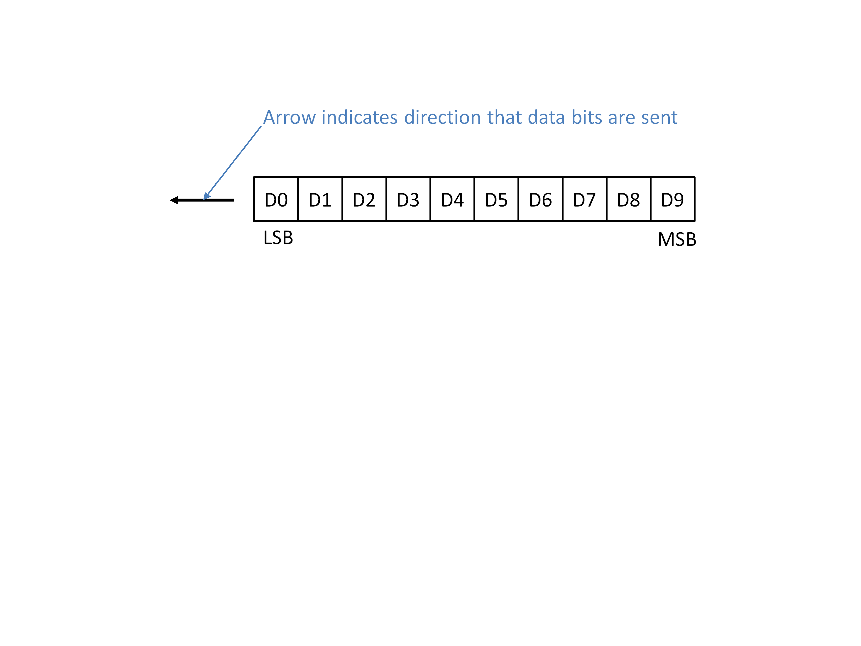 Figure 31: Convention for first bit to be sent
Graphical representation of packets
Packets and their component fields are represented graphically as shown in Figure 32. The arrow indicates the direction that the packet is travelling, so the destination address field is sent first.
 Figure 32: Graphical packet notation
State diagram notation
State diagrams are used to represent the behaviour of several parts of the SpaceFibre protocol. All state diagrams in this Standard use the style shown in Figure 33. States are represented by ellipses with the state name written inside the ellipse in bold. Actions to take while in a particular state are written in italics inside the ellipse underneath the state name. Transitions from one state to another are indicated by arrows. The event that causes a transition is written alongside the arrow. Unconditional transitions are indicated by arrows without an event name written next to them. Reset conditions are indicated by transition arrows that start in empty space.
A condition in a state relates to that state only, unless there is a specific statement to the contrary. For example, the condition “When three INIT3 control words are received” expressed in a particular state, means three INIT3 control words being received while in that state.
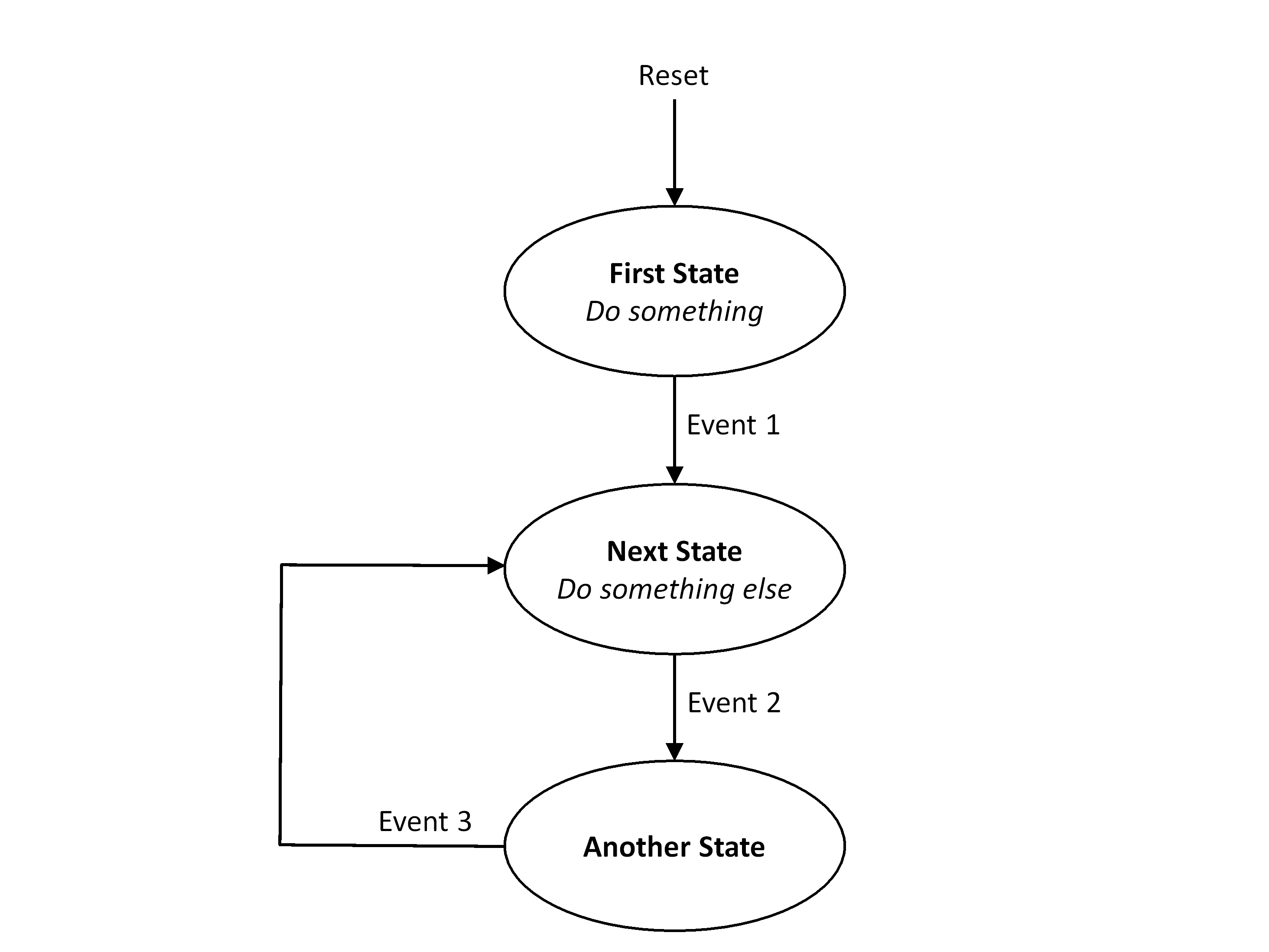 Figure 33: State diagram style
UML diagram notation
UML diagrams in this document use the notation illustrated in Figure 34.
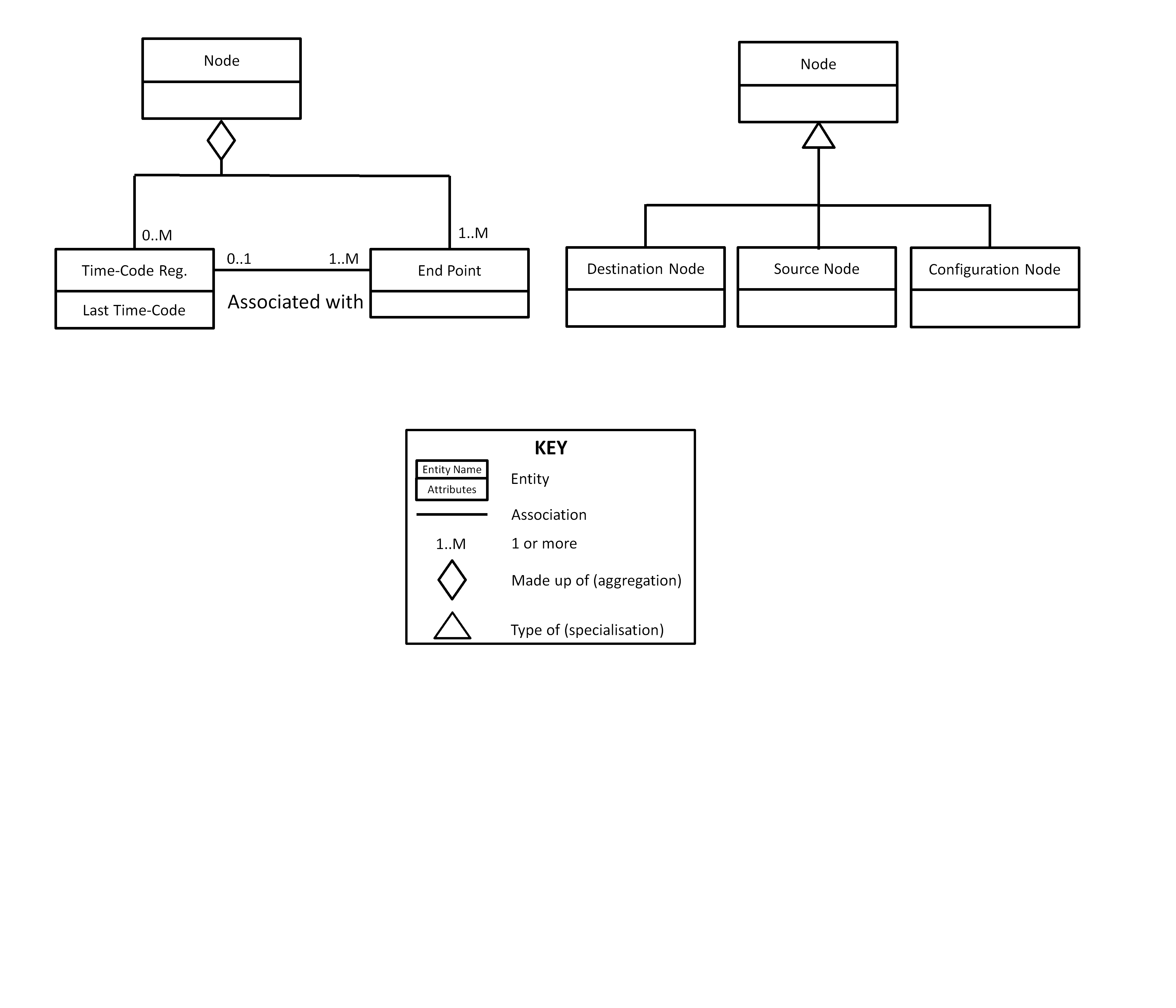 Figure 34: UML notation
Each entity (or object) is shown as a rectangle divided in two by a horizontal line. The name of the entity is at the top above the line and a list of key attributes is below the line. Only those attributes that are particularly relevant to understanding a diagram are shown, for example “Last Time-Code” in the Time-Code Register.
A diamond is used to represent aggregation and is translated as “is made up of”, hence in Figure 34 a node is made up of one or more (1..M) end-points and zero or more (0..M) time-code registers. The number at the end of the line shows the cardinality of the relationship and is either a number (e.g. 1) or a range (e.g. 1..M) with M representing more or many.
A triangle represents generalisation in one direction (reading in the direction the triangle is pointing) and specialisation in the other. So, in Figure 34, a destination node is a special type of node. Reading in the other direction, a node is a generalisation of destination node, source node and configuration node.
Other associations between entities are shown as lines connecting the two objects. A name capturing the intent of the association is written alongside the line. If the association is general, no name needs to be given to it. Hence, in Figure 34, each end-point is associated with zero or more time-code registers and each time-code register is associated with 1 or more end-points.
D/K notation for 8B/10B characters
The 8B/10B encoding scheme uses a particular type of notation for describing data and control characters. A data character is in the format D/xx.y where xx is the decimal representation of the least significant 5 bits of the data byte being sent and y is the decimal representation of the most significant three bits of the data byte being sent. Similarly, a control character is represented by K/xx.y. This is illustrated in Figure 35 along with two examples.
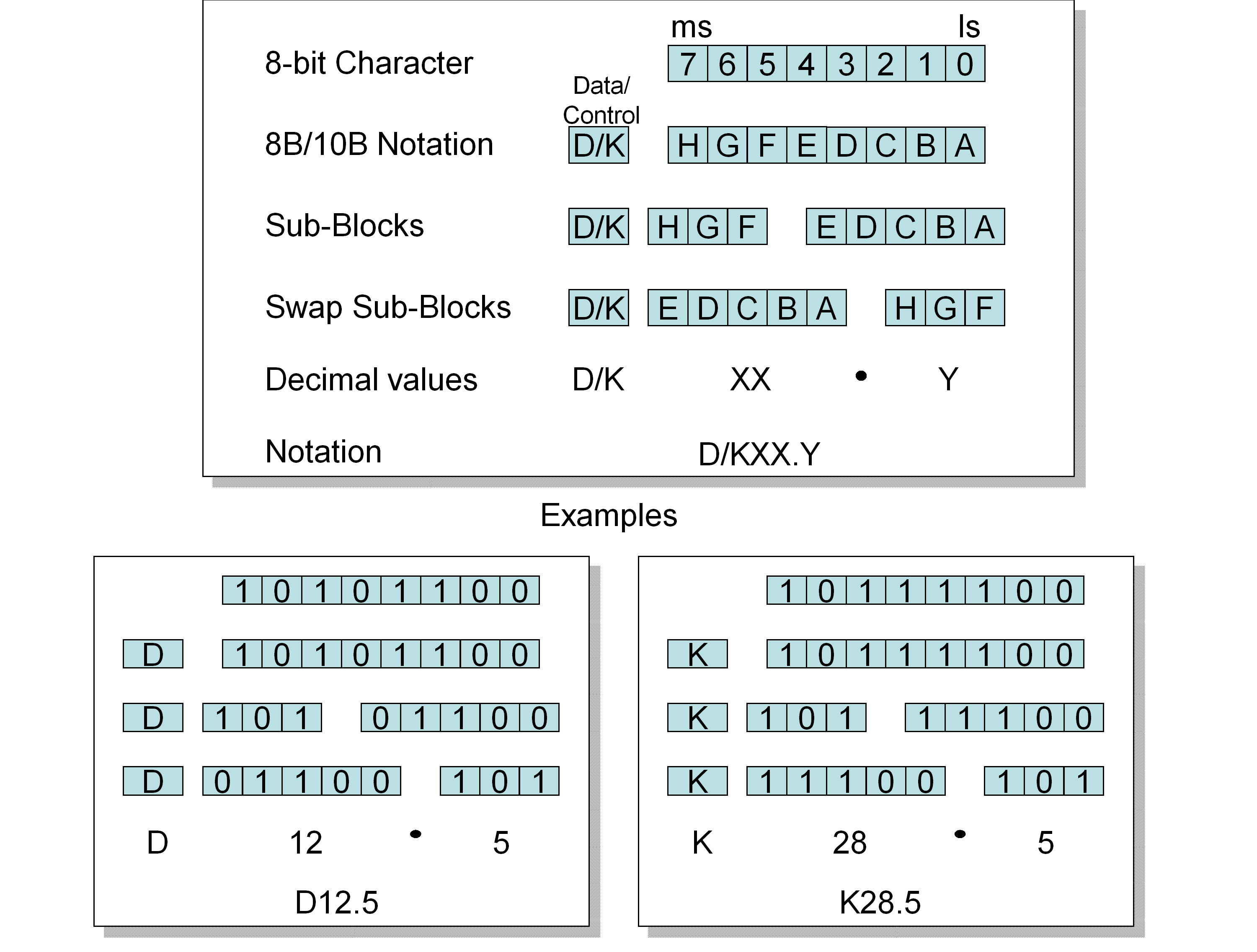 Figure 35: D/K notation for 8B/10B characters
Nomenclature
The following nomenclature applies throughout this document:
The word “shall” is used in this Standard to express requirements. All the requirements are expressed with the word “shall”.
The word “should” is used in this Standard to express recommendations. All the recommendations are expressed with the word “should”.
It is expected that, during tailoring, recommendations in this document are either converted into requirements or tailored out.
The words “may” and “need not” are used in this Standard to express positive and negative permissions, respectively. All the positive permissions are expressed with the word “may”. All the negative permissions are expressed with the words “need not”.
The word “can” is used in this Standard to express capabilities or possibilities, and therefore, if not accompanied by one of the previous words, it implies descriptive text.
In ECSS “may” and “can” have completely different meanings: “may” is normative (permission), and “can” is descriptive.
The present and past tenses are used in this Standard to express statements of fact, and therefore they imply descriptive text.
Principles
SpaceFibre purpose
SpaceFibre is a multi-Gigabit/s data link and network technology specifically designed for spaceflight applications including high data-rate payload data-handling such as synthetic aperture radar (SAR), multi-spectral imaging systems and fast mass-memory units. SpaceFibre data links are full-duplex and run over either electrical or fibre-optic media. SpaceFibre includes built-in, very efficient, quality of service (QoS) and fault detection, isolation and recovery (FDIR) techniques, which simplify the use of SpaceFibre enormously; providing substantial system level benefits without requiring the implementation of complex, performance limiting, software protocols.
SpaceFibre is backwards compatible with SpaceWire (ECSS-E-ST-50-12) at the packet level allowing easy bridging between SpaceWire and SpaceFibre, so that existing SpaceWire devices can be incorporated into a SpaceFibre network and take advantage of its performance, and QoS and FDIR capabilities. SpaceFibre provides robust, long distance communications for launcher applications and supports avionics applications with deterministic delivery constraints. SpaceFibre enables a common on-board network technology to be used across many different mission applications resulting in cost reduction and design reusability. SpaceFibre performs the following:
Supports high data rate payloads,
Carries data from existing SpaceWire instruments,
Performs low latency time-distribution,
Provides low latency event signalling,
Provides deterministic data delivery to support guidance and navigation control applications,
Supports any network topology.
SpaceFibre overview
An overview of the SpaceFibre protocol stack is provided in Figure 41.
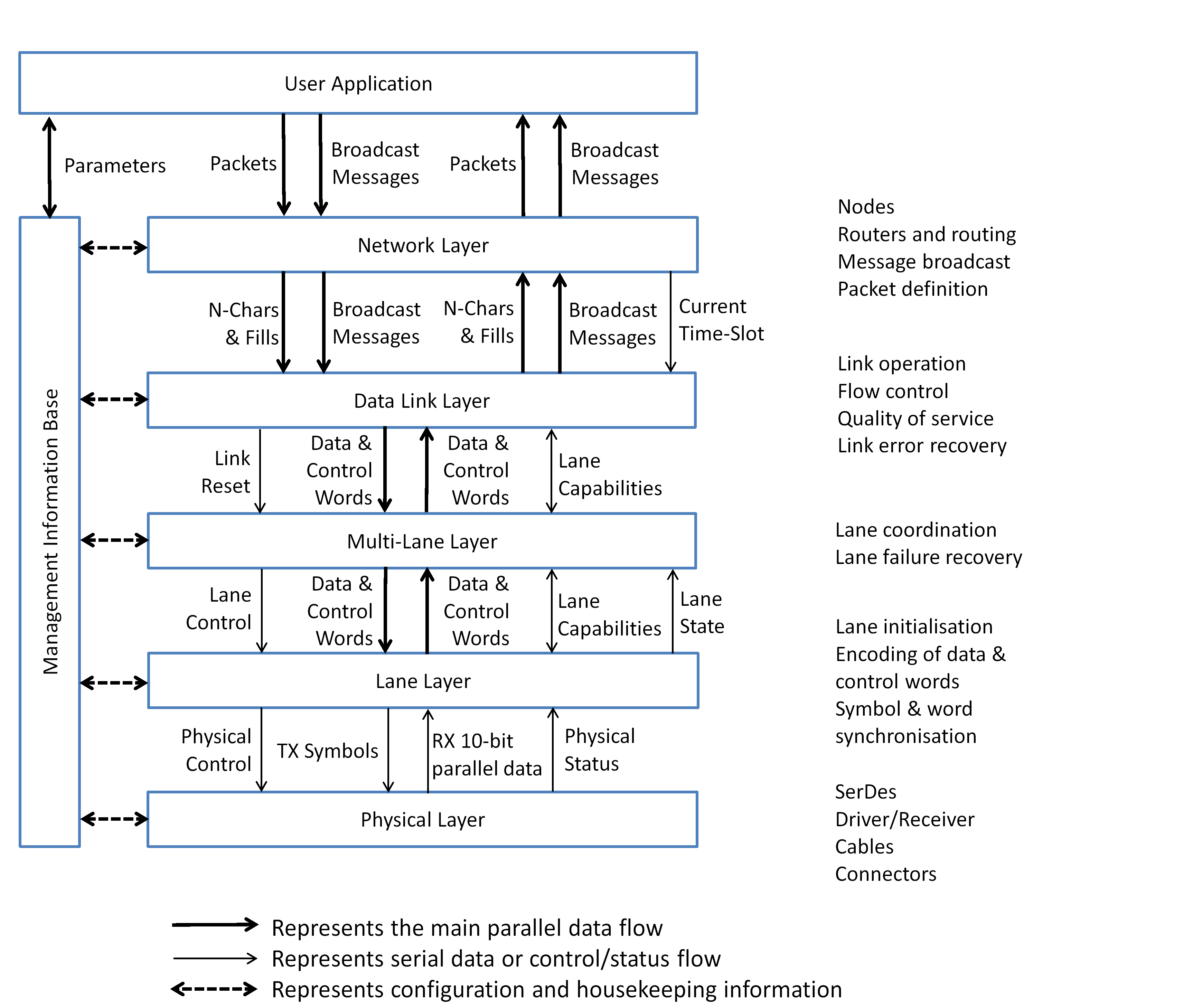 Figure 41: Overview of SpaceFibre protocol stack
There are five conceptual layers to the SpaceFibre protocol: Network layer, Data Link layer, Multi-Lane layer, Lane layer and Physical layer.
The Network layer is responsible for the transfer of application information over a SpaceFibre network. It provides two services: Packet Transfer service and Broadcast Message service. The Packet Transfer service transfers SpaceFibre packets over the SpaceFibre network, using the same packet format and routing concepts as SpaceWire uses. SpaceFibre supports both path and logical addressing. The Broadcast Message service is responsible for broadcasting short messages (8 bytes) to all nodes on the network. These messages can carry time and synchronisation signals and be used to signal the occurrence of various events on the network.
The Data Link layer is responsible for providing quality of service (QoS) and managing the flow of information over a SpaceFibre link, using one or more virtual channels with independent flow control. It frames the information to be sent over the link to support QoS and optionally scrambles the packet data to reduce electromagnetic emissions. The Data Link layer is also responsible for error recovery, by resending frames and control words that have been detected by the far-end of a link as erroneous or missing. SpaceFibre is very resilient to transient errors.
The Multi-Lane layer is responsible for operating several SpaceFibre lanes in parallel to provide higher data throughput. In the event of a lane failing the Multi-Lane layer provides support for graceful degradation, automatically spreading the traffic over the remaining working lanes. A SpaceFibre link is the logical data link, which can comprise one or more physical lanes. The use of multiple lanes is optional.
The Lane layer is responsible for establishing communications across a SpaceFibre lane, for encoding data and control words into symbols, for sending and receiving symbols over the lane, for decoding the received symbols into data and control words, and for re-establishing communications across the lane when an error occurs on a lane. 8B/10B encoding is used which provides a DC balanced signal that can be AC coupled to provide galvanic isolation.
The Physical layer is, on the transmitter side, responsible for serialising the 8B/10B symbols and for sending them over the physical medium. On the receiver side, the Physical layer is responsible for recovering the clock and data from the serial bit stream. Both electrical cables and fibre-optic cables are supported by SpaceFibre.
The Management Information Base is responsible for configuring, controlling and monitoring the status of all the layers in the SpaceFibre protocol stack.
The service interface specifications for each OSI layer within the SpaceFibre protocol stack are provided in clause 6.
The connectors, cable and cable assemblies specified in the Physical layer are divided into several types. For example, for the electrical medium, the following types are specified:
Type-A connectors, cables and cable assemblies are specific, fully specified parts for flight use.
Type-B provides a generic specification of the electrical properties needed allowing a range of different flight capable solutions to be implemented.
Type-C are specific, fully defined parts for electronic ground support applications.
Type-D provides a generic specification of the electrical properties for electronic ground support cables.
Type-A and Type-C are for immediate use, Type-B and Type-D allow for innovation and more capable solutions to be developed in future.
Requirements
Overview
Clause 5 provides the normative requirements for SpaceFibre. It is separated into the following functional layers.
Clause 5.2 specifies the SpaceFibre protocol stack and conceptual architecture of a SpaceFibre port.
Clause 5.3 specifies the formats of the control words, characters, frames and packets used by SpaceFibre.
Clause 5.4 specifies the Physical layer which covers the specification of the serialiser, deserialiser, line drivers, line receivers, connectors, cables, and cable assemblies.
Clause 5.5 specifies the Lane layer which performs lane initialisation, encoding of characters into symbols, receive symbol and word synchronisation, decoding of symbols into characters, and compensation for differences in clocking speeds at the two ends of the lane.
Clause 5.6 specifies the Multi-Lane layer which supports several lanes operating together to provide a single link of higher bandwidth than a single lane.
Clause 5.7 specifies the Data Link layer which provides link quality of service (QoS) and fault detection, isolation and recovery (FDIR).
Clause 5.8 specifies the network layer which covers SpaceFibre packets, nodes, routing switches, networks and broadcast messages.
Clause 5.9 specifies the Management Information Base.
Protocol stack and interface architecture
General
The SpaceFibre protocol stack shall have a Network layer, Data Link layer, Multi-Lane layer, Lane layer, Physical layer and Management Information Base.
- 1 The SpaceFibre protocol stack is illustrated in Figure 51 for a single lane and in Figure 52 for a multi-lane link. The service interfaces for each layer of the SpaceFibre protocol stack are specified in clause 6.
- 2 From the perspective of the layers of the OSI Model, the Lane layer and the Multi-Lane layer are sublayers of the Data Link layer. The Data Link, Multi-Lane and Lane layers form one layer from the implementation perspective. The separation into layers has been done to group related functionalities together for ease of understanding.
The Multi-Lane layer may be omitted, when only a single lane is being used.
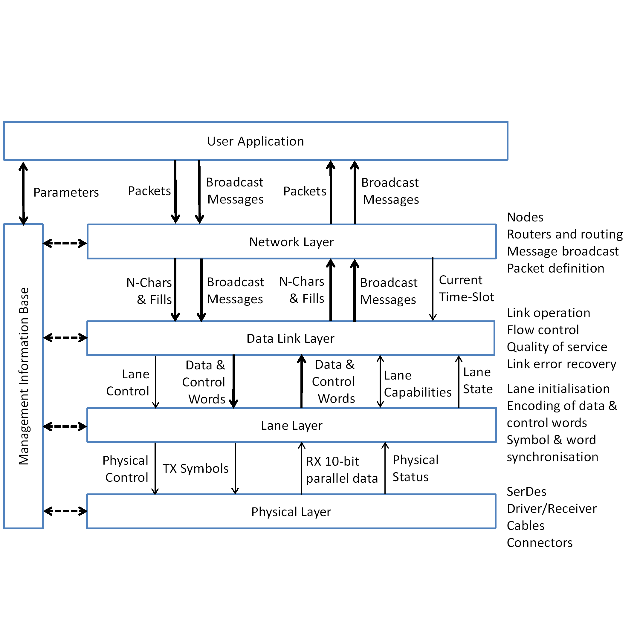 Figure 51: SpaceFibre protocol stack - single-lane
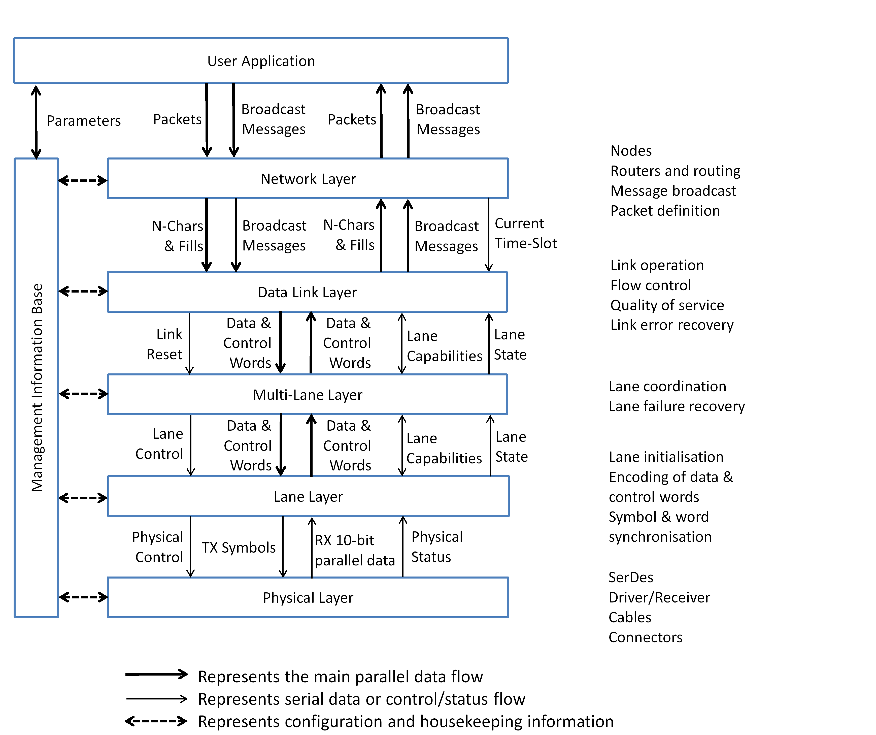 Figure 52: SpaceFibre protocol stack - multi-lane
Network layer
The SpaceFibre Network layer shall provide two principal services:
- A Packet Transfer service which sends and receives packets over a SpaceFibre network.
- A Broadcast Message service which sends and receives broadcast messages over a SpaceFibre network.
A SpaceFibre implementation shall support the Packet Transfer service and the Broadcast Message service.
The SpaceFibre Network layer shall accept service requests from user applications.
The SpaceFibre Network layer shall use the services of the SpaceFibre Data Link layer.
Data Link layer
The SpaceFibre Data Link layer shall provide three services:
- A Virtual Channel service, supporting multiple virtual channels with independent flow control, which sends and receives N-Chars and Fills, the components of packets, over a SpaceFibre link.
- A Broadcast service which sends and receives broadcast messages over a SpaceFibre link.
- A Schedule Synchronisation service which receives current time-slot information in order to synchronise the scheduled QoS.
The Data Link layer shall accept service requests from the Network layer.
The Data Link layer shall use the services of the SpaceFibre Multi-Lane or Lane layer.
Multi-Lane layer
The SpaceFibre Multi-Lane layer is an optional layer which shall provide three services:
- A Transfer Word service which sends data and control words over a SpaceFibre link and which receives data and control words over a SpaceFibre link.
- A Link Reset service which resets all the lanes of a link.
- A Capabilities service which sets the capabilities of each lane at the near-end of a link and reports the capabilities of each lane at the far-end of the link.
The Multi-Lane layer shall accept service requests from the Data Link layer.
The Multi-Lane layer shall use the services of the SpaceFibre Lane layer.
Lane layer
The SpaceFibre Lane layer shall provide three services:
- A Transfer Word service which sends data and control words over a SpaceFibre lane and which receives data and control words over a SpaceFibre link.
- A Control service which controls the operation of the lanes in a link, using the TxOnly, RxOnly, FarEndActive, and LaneReset signals for each lane and which provides the current state of the Lane Initialisation state machine.
- A Capabilities service which sets the capabilities of each lane at the near-end of a link and reports the capabilities of each lane at the far-end of the link.
The Lane layer shall accept service requests from the SpaceFibre Data Link layer or Multi-Lane layer.
The Lane layer shall use the services of the SpaceFibre Physical layer.
Physical layer
The SpaceFibre Physical layer shall provide two services:
- A Transfer Symbol service which serialises the symbols provided by the Lane layer and transmits them over the physical medium, and which receives the data signal from the physical medium, de-serialises it to produce 10-bit parallel data and passes it to the Lane layer.
- A Control service which controls the operation of the line driver, line receiver and SerDes and which reports the status of the line receiver and SerDes. The SpaceFibre Physical layer shall accept service requests from the Lane layer.
Management Information Base
The SpaceFibre Management Information Base shall provide one service:
- A Management service which writes control or configuration information to all SpaceFibre layers and which reads the status or current configuration or control values of all SpaceFibre layers.
The SpaceFibre Management Information Base shall accept service requests from a user application.
The SpaceFibre Management Information Base shall have direct access to the relevant configuration parameters, control parameters and status parameters in the Network layer, Data Link layer, Multi-Lane layer, Lane layer and Physical layer.
Formats
Control words and encoding/decoding
Several types of control words shall be used by SpaceFibre:
- Lane control words.
- Multi-Lane control words.
- Data Link control words.
- Receive error indication control word, which is generated in the receiver and is not sent over the SpaceFibre link. SpaceFibre shall encode/decode information to send over a lane using 8B/10B encoding/decoding.
8B/10B encode/decode
The SpaceFibre port shall use 8B/10B encoding to encode each 8-bit data character or control character into a 10-bit symbol that is transmitted.
To ensure DC balancing of the transmitted signal, account shall be kept of the current running disparity in the transmitter.
When an 8-bit data character or control character is being encoded and the current running disparity is positive, the symbol for that data character or control character which has negative or neutral disparity shall be used.
When an 8-bit data character or control character is being encoded and the current running disparity is negative, the symbol for that data character or control character which has positive or neutral disparity shall be used.
Upon reset the current running disparity shall be set to plus one or minus one.
To detect disparity errors, account shall be kept of the current running disparity in the receiver.
If the current running disparity is more than plus one or less than minus one, the receiver shall indicate a disparity error.
When a disparity error occurs, the current running disparity in the receiver shall be set to plus one if it was greater than plus one and to minus one if it was less than minus one.
When a symbol is received, it shall be decoded into an 8-bit data character or control character using the 8B/10B symbol table.
The 8B/10B encoder shall encode the least-significant five-bits of a data character or control character as specified in Table 51 and the most significant three bits as specified in Table 52.
Table 51: 5B/6B encoding
|
Input
|
Output
| ||
|
Data Input
|
Data bits 43210
|
Current Running Disparity -ve
|
Current Running Disparity +ve
|
|
D00.y
|
00000
|
100111
|
011000
|
|
D01.y
|
00001
|
011101
|
100010
|
|
D02.y
|
00010
|
101101
|
010010
|
|
D03.y
|
00011
|
110001
| |
|
D04.y
|
00100
|
110101
|
001010
|
|
D05.y
|
00101
|
101001
| |
|
D06.y
|
00110
|
011001
| |
|
D07.y
|
00111
|
111000
|
000111
|
|
D08.y
|
01000
|
111001
|
000110
|
|
D09.y
|
01001
|
100101
| |
|
D10.y
|
01010
|
010101
| |
|
D11.y
|
01011
|
110100
| |
|
D12.y
|
01100
|
001101
| |
|
D13.y
|
01101
|
101100
| |
|
D14.y
|
01110
|
011100
| |
|
D15.y
|
01111
|
010111
|
101000
|
|
D16.y
|
10000
|
011011
|
100100
|
|
D17.y
|
10001
|
100011
| |
|
D18.y
|
10010
|
010011
| |
|
D19.y
|
10011
|
110010
| |
|
D20.y
|
10100
|
001011
| |
|
D21.y
|
10101
|
101010
| |
|
D22.y
|
10110
|
011010
| |
|
D/K23.y
|
10111
|
111010
|
000101
|
|
D24.y
|
11000
|
110011
|
001100
|
|
D25.y
|
11001
|
100110
| |
|
D26.y
|
11010
|
010110
| |
|
D/K27.y
|
11011
|
110110
|
001001
|
|
D28.y
|
11100
|
001110
| |
|
K28.y
|
11100
|
001111
|
110000
|
|
D/K29.y
|
11101
|
101110
|
010001
|
|
D/K30.y
|
11110
|
011110
|
100001
|
|
D31.y
|
11111
|
101011
|
010100
|
Table 52: 3B/4B encoding
|
Input
|
Output
| ||
|
Data Input
|
Data bits 765
|
5B/6B Disparity -ve
|
5B/6B Disparity +ve
|
|
D/Kxx.0
|
000
|
1011
|
0100
|
|
Dxx.1
|
001
|
1001
| |
|
Kxx.1
|
001
|
0110
|
1001
|
|
Dxx.2
|
010
|
0101
| |
|
Kxx.2
|
010
|
1010
|
0101
|
|
D/Kxx.3
|
011
|
1100
|
0011
|
|
D/Kxx.4
|
100
|
1101
|
0010
|
|
Dxx.5
|
101
|
1010
| |
|
Kxx.5
|
101
|
0101
|
1010
|
|
Dxx.6
|
110
|
0110
| |
|
Kxx.6
|
110
|
1001
|
0110
|
|
Dxx.7
|
111
|
1110/0111
|
0001/1000
|
|
Kxx.7
|
111
|
0111
|
1000
|
Lane control words
General
The lane control words shall be used to initialise a SpaceFibre lane, to indicate loss of signal, and to indicate that a lane is about to go into standby.
The lane control words are constructed as shown in Table 53.
Table 53: Lane control words
|
Name
|
Control word
|
Function
|
|
SKIP
|
Comma, LLCW, SKIP, SKIP
|
Sent every 5000 control words or data words to support the receiver elastic buffer operation.
|
|
IDLE
|
Comma, LLCW, IDLE, IDLE
|
Sent when the link is initialised and the Data Link or Multi-Lane layer does not provide valid words to be sent.
|
|
INIT1
|
Init Comma, LLCW, INIT1, INIT1
|
Sent as part of the initialisation handshake.
|
|
inverse INIT1
|
Init Comma, iLLCW, iINIT1, iINIT1
|
Received as part of the initialisation handshake if the Physical layer signals are inverted.
|
|
INIT2
|
Init Comma, LLCW, INIT2, INIT2
|
Sent as part of the initialisation handshake.
|
|
inverse INIT2
|
Init Comma, iLLCW, iINIT2, iINIT2
|
Received as part of the initialisation handshake if the Physical layer signals are inverted.
|
|
INIT3
|
Init Comma, LLCW, INIT3, Capability
|
Sent as part of the initialisation handshake.
|
|
STANDBY
|
Comma, LLCW, STBY, Reason
|
Indicates that the transmitter is moving to the Standby state and about to tri-state its driver. This can be used to save power when the host has no data to transmit and no data is currently being received. The Standby Reason field can be used to indicate the reason why the STANDBY control word was sent or provide other status information.
|
|
LOST_SIGNAL
|
Comma, LLCW, LOS, Reason
|
Indicates that the end of the link sending the LOST_SIGNAL control word has lost signal on its receiver. The Reason field is used to indicate the cause of the NoSignal.
|
SKIP control word
The SKIP control word shall begin with a comma, K28.7, which is in the least significant symbol position of the control word and is sent first.
The second symbol in the SKIP control word shall be the Lane Layer Control Word, LLCW, identifier, which has the value D14.6 and identifies the control word as being a control word generated and used by the Lane layer.
The third symbol in the SKIP control word shall identify the Lane layer control word as being a SKIP control word, and has the value D31.3.
The fourth and final symbol in the SKIP control word shall be a copy of the third symbol.
The SKIP control word is used to support operation of the data signalling rate compensation in the SpaceFibre receiver, see 5.5.3.
IDLE control word
The IDLE control word shall begin with a comma, K28.7, which is in the least significant symbol position of the control word and is sent first.
The second symbol in the IDLE control word shall be the Lane Layer Control Word, LLCW, identifier, which has the value D14.6 and identifies the control word as being a control word generated and used by the Lane layer.
The third symbol in the IDLE control word shall identify the Lane Layer Control Word as being an IDLE control word, and has the value D15.6.
The fourth and final symbol in the IDLE control word shall be a copy of the third symbol.
The IDLE control word is sent, after initialisation, to keep the lane running when there is no other information to send.
INIT1 control word
The INIT1 control word, used during lane initialisation, shall begin with an initialisation comma, K28.5, which is in the least significant symbol position of the control word and is sent first.
The second symbol in the INIT1 control word shall be the Lane Layer Control Word, LLCW, identifier, which has the value D14.6 and identifies the control word as being a control word generated and used by the Lane layer.
The third symbol in the INIT1 control word shall identify the Lane Layer Control Word as being an INIT1 control word, and has the value D6.2.
The fourth and final symbol in the INIT1 control word shall be a copy of the third symbol.
Inverse INIT1 control word
The Inverse INIT1 control word, iINIT1, shall begin with an initialisation comma, K28.5, which is in the least significant symbol position of the control word and is received first.
The second symbol in the Inverse INIT1 control word shall be the Inverse Lane Layer Control Word, iLLCW, identifier, which has the value D17.1 and identifies the control word as being a control word generated and used by the Lane layer.
The third symbol in the Inverse INIT1 control word shall identify the Lane Layer Control Word as being an Inverse INIT1 control word, and has the value D25.5.
The fourth and final symbol in the Inverse INIT1 control word shall be a copy of the third symbol.
The Inverse INIT1 control word shall not be generated by the SpaceFibre port.
The Inverse INIT1 is formed when the PCB layout in a SpaceFibre transmitter or receiver crosses over the two signals, CML+ and CML-, making up the differential signal.
INIT2 control word
The INIT2 control word, used during lane initialisation, shall begin with an initialisation comma, K28.5, which is in the least significant symbol position of the control word and is sent first.
The second symbol in the INIT2 control word shall be the Lane Layer Control Word, LLCW, identifier, which has the value D14.6 and identifies the control word as being a control word generated and used by the Lane layer.
The third symbol in the INIT2 control word shall identify the Lane Layer Control Word as being an INIT2 control word, and has the value D6.5.
The fourth and final symbol in the INIT2 control word shall be a copy of the third symbol.
Inverse INIT2 control word
The Inverse INIT2 control word, iINIT2, shall begin with an initialisation comma, K28.5, which is in the least significant symbol position of the control word and is received first.
The second symbol in the Inverse INIT2 control word shall be the Inverse Lane Layer Control Word, iLLCW, identifier, which has the value D17.1 and identifies the control word as being a control word generated and used by the Lane layer.
The third symbol in the Inverse INIT2 control word shall identify the Lane Layer Control Word as being an Inverse INIT2 control word, and has the value D25.2.
The fourth and final symbol in the Inverse INIT2 control word shall be a copy of the third symbol.
The Inverse INIT2 control word shall not be generated by the SpaceFibre port.
The Inverse INIT2 is formed when the PCB layout in a SpaceFibre transmitter or receiver crosses over the two signals, CML+ and CML-, making up the differential signal.
INIT3 control word
The INIT3 control word, used during lane initialisation, shall begin with an initialisation comma, K28.5, which is in the least significant symbol position of the control word and is sent first.
The second symbol in the INIT3 control word shall be the Lane Layer Control Word, LLCW, identifier, which has the value D14.6 and identifies the control word as being a control word generated and used by the Lane layer.
The third symbol in the INIT3 control word, which has the value D24.1, shall identify the Lane Layer Control Word as being an INIT3 control word.
The fourth and final symbol in the INIT3 control word, Capability, shall be a data symbol with any value from D0.0 to D31.7 and encode a data character containing control flags and information about the capability of the lane.
It is not necessary for the Capability field to have valid inverse symbols, since by the time INIT3s are being sent any necessary receiver inversion is already completed.
The Capability data character shall contain several fields as follows:
- Bit 0: the INIT3LinkResetFlag.
- Bit 1: the INIT3LaneStart flag.
- Bit 2: the INIT3DataScrambled flag.
- Bit 3: the INIT3Multi-LaneCapable flag.
- Bit 4: the INIT3RoutingSwitch flag.
- Bits 5 to 7: reserved, which are set to zero when transmitted and ignored when received. The INIT3LinkResetFlag shall take on one of the following values:
- INIT3LinkResetFlag=0, which means that at least one lane of the SpaceFibre port sending the INIT3 control word has been in the Active state at least once since the last link reset or power on reset.
- INIT3LinkResetFlag=1, which means that the SpaceFibre port sending the INIT3 control word has not had any lane in the Active state since the last link reset or power on reset.
The reset values of various parameters are specified in clause 5.9.
The INIT3LaneStart flag shall take on one of the following values:
- INIT3LaneStart=0, which means that the SpaceFibre lane sending the INIT3 control word has its LaneStart management parameter NOT set.
- INIT3LaneStart=1, which means that the SpaceFibre lane sending the INIT3 control word has its LaneStart management parameter set. The INIT3DataScrambled flag shall take on one of the following values:
- INIT3DataScrambled=0, which means that the SpaceFibre port sending the INIT3 control word does NOT scramble data in its data frames.
- INIT3DataScrambled=1, which means that the SpaceFibre port sending the INIT3 control word does scramble data in its data frames. The INIT3Multi-LaneCapable flag shall take on one of the following values:
- INIT3Multi-LaneCapable=0, which means that the SpaceFibre lane sending the INIT3 control word is NOT capable of operating as a lane in a multi-lane link.
- INIT3Multi-LaneCapable=1, which means that the SpaceFibre lane sending the INIT3 control word is capable of operating as a lane in a multi-lane link. The INIT3RoutingSwitch flag shall take on one of the following values:
- INIT3RoutingSwitch=0, which means that the SpaceFibre lane sending the INIT3 control word is NOT a lane belonging to a link of a routing switch.
- INIT3RoutingSwitch=1, which means that the SpaceFibre lane sending the INIT3 control word is a lane belonging to a link of a routing switch.
STANDBY control word
The STANDBY control word shall begin with a comma, K28.7, which is in the least significant symbol position of the control word and is sent first.
The second symbol in the STANDBY control word shall be the Lane Layer Control Word, LLCW, identifier, which has the value D14.6 and identifies the control word as being a control word generated and used by the Lane layer.
The third symbol in the STANDBY control word shall identify the Lane Layer Control Word as being a STANDBY control word, and has the value D30.3.
The fourth and final symbol in the STANDBY control word, Standby Reason field, shall be a data symbol with any value from D0.0 to D31.7 and encode a data character containing information about the reason that the STANDBY symbol was sent.
The Standby Reason field may be set to D0.0, if the SpaceFibre interface does not support the sending of the reason for the lane standby.
The STANDBY control word is used to inform the far-end of a lane that the SpaceFibre interface is about to go into standby mode with its line driver turned off.
The Standby Reason data character shall contain several fields as follows:
- Bit 0: When set to 1, indicates that the reason field is supported and the other bits are valid, while when set to 0, indicates that the reason field is not supported and the other bits are all set to 0 on transmit and ignored when received.
- Bit 1: When set to 1, indicates that the sender of the STANDBY asserted AutoStart after the lane disconnects, which allows the receiver of the STANDBY to start the lane again, while when set to 0, means that AutoStart is de-asserted after the lane disconnects, so the receiver of the STANDBY cannot decide to start the lane again.
- Bit 2: When set to 1, indicates that the sender of the STANDBY can later assert LaneStart and try to start the lane, while when set to 0, indicates that LaneStart remains de-asserted.
- Bit 3: When set to 1, indicates that bits 4-7 of the Standby Reason field contain implementation dependent information, while when set to 0, indicates that bits 4-7 of the Standby Reason field are reserved.
- Bits 4 to 7: When bit 3 is set to 1, bits 4 to 7 contain implementation dependent information about the reason of the lane being disabled, while when bit 3 is set to 0, bits 4 to 7 are reserved being set to zero when transmitted and ignored when received.
LOST_SIGNAL control word
The LOST_SIGNAL control word shall begin with a comma, K28.7, which is in the least significant symbol position of the control word and is sent first.
The second symbol in the LOST_SIGNAL control word shall be the Lane Layer Control Word, LLCW, identifier, which has the value D14.6 and identifies the control word as being a control word generated and used by the Lane layer.
The third symbol in the LOST_SIGNAL control word shall identify the Lane Layer Control Word as being a LOST_SIGNAL control word, and has the value D4.3.
The fourth and final symbol in the LOST_SIGNAL control word, Lost Signal Reason field, shall be a data symbol with any value from D0.0 to D2.0 and encode a data character containing information about the cause of the loss of signal.
The Lost Signal Reason data character shall contain two fields as follows:
- Bit 0 to 1: the LOS_Cause status bits.
- Bits 2 to 7: reserved, which are set to zero when transmitted and ignored when received. The LOS_Cause status bits shall take on one of the following values:
- LOS_Cause=0b00, which means that the receiver in the SpaceFibre port sending the LOST_SIGNAL control word is not receiving a strong enough signal.
- LOS_Cause=0b01, which means that the receiver in the SpaceFibre port sending the LOST_SIGNAL control word is detecting too many receive errors to operate reliably.
- LOS_Cause=0b10, which means that the receiver in the SpaceFibre port sending the LOST_SIGNAL control word received an INIT1 while in the Active state and the lane is not an RxOnly lane.
Multi-Lane control words
General
Multi-Lane control words shall be used to align control words flowing over multiple lanes and to support the initialisation of unidirectional lanes in an asymmetric link.
Multi-Lane control words are constructed as illustrated in Table 54.
Table 54: Multi-Lane control words
|
Name
|
Control word
|
Function
|
|
ACTIVE
|
Comma, ACTIVE, ACT_LS, ACT_MS
|
Unidirectional lane initialisation.
|
|
ALIGN
|
Comma, ALIGN, LANES, iLANES
|
Multi-Lane alignment.
|
|
PAD
|
Comma, Fill, Fill, Fill
|
Multi-Lane padding.
|
ACTIVE control word
The ACTIVE control word shall begin with a comma, K28.7, which is in the least significant symbol position of the control word and is sent first.
The second symbol in the ACTIVE control word shall identify the control word as being an ACTIVE control word, and has the value D0.1.
The third symbol in the ACTIVE control word shall contain the least-significant 8 bits of the 16-bit ACT field which has one bit for each possible lane, with bit N corresponding to lane N.
The fourth symbol in the ACTIVE control word shall contain the most-significant 8 bits of the 16-bit ACT field.
When a particular bit is set in the ACT field of an ACTIVE control word, it shall indicate that the corresponding lane at the end of the link sending the ACTIVE control word is in the Active state.
ALIGN control word
The ALIGN control word shall begin with a comma, K28.7, which is in the least significant symbol position of the control word and is sent first.
The second symbol in the ALIGN control word shall identify the control word as being an ALIGN control word, and has the value D23.3.
The third symbol in the ALIGN control word shall contain the 8-bit LANES field which comprises two sub-fields: #Lanes, bits 0-3, and Lane Number, bits 4-7.
The 4-bit #Lanes field of the ALIGN control word shall contain the number of lanes that are in the Active state at the end of the link sending the ALIGN control word, where a value of 0b0000 means that 16 lanes are in the Active state.
The 4-bit Lane Number field of the ALIGN control word shall contain the lane number of the lane used to send the ALIGN control word.
The fourth and final symbol in the ALIGN control word shall contain the bitwise inverse of the third symbol, which is used to confirm the integrity of the LANES field when received before its contents are acted upon.
PAD control word
The PAD control word shall begin with a comma, K28.7, which is in the least significant symbol position of the control word and is sent first.
The second, third and fourth symbols in the PAD control word shall all have the same value, K27.7, identifying the control word as being a PAD control word.
Data Link control words
Framing control words
Use of framing control words
Framing control words shall be used to encapsulate the data frames, broadcast frames, and idle frames being sent across the link.
- 1 Framing control words are illustrated in Table 55.
- 2 The specific values of the K-codes and D-codes used in the control words have been designed to maximize the Hamming distance between one symbol and any other symbol, helping to reduce the likelihood of an undetected error.
Table 55: Data framing control words
|
Name
|
Control word
|
Function
|
|
SDF
|
Comma, SDF, VC, Reserved
|
Start of Data Frame.
|
|
EDF
|
EDF, SEQ_NUM, CRC_LS, CRC_MS
|
End of Data Frame.
|
|
SBF
|
Comma, SBF, BC, B_TYPE
|
Start of Broadcast Frame.
|
|
EBF
|
EBF, STATUS, SEQ_NUM, CRC
|
End of Broadcast Frame.
|
|
SIF
|
Comma, SIF, SEQ_NUM, CRC
|
Start of Idle Frame.
|
Sequence Number
The Sequence Number, SEQ_NUM, used in the Start of Idle Frame, SIF, End of Data Frame, EDF, End of Broadcast Frame, EBF, and in the FCT and ACK, NACK and FULL control words, shall contain two fields as follows:
- Bit 0 to 6: a 7-bit sequence count.
- Bit 7: a sequence count polarity flag.
See clause 5.3.5.2 for details of the FCT, and clause 5.3.5.3 for details of ACK, NACK and FULL.
The 7-bit Sequence Count field shall contain a modulo-128 integer, which is incremented immediately prior to the sending of a new data frame, broadcast frame or FCT.
The 7-bit Sequence Count field shall be set to zero following a link reset.
The polarity flag shall be set to zero following a link reset.
If the polarity flag is zero, the polarity of the Sequence Number shall be considered positive.
If the polarity flag is one, the polarity of the Sequence Number shall be considered negative.
The polarity flag shall be inverted every time a new error recovery is started.
The polarity flag is used to distinguish frames, ACKs and NACKs sent before an error recovery procedure starts, indicated by a RETRY control word, from those that follow the start of the error recovery. Each time a new error recovery procedure starts and a RETRY control word is sent, the polarity bit is flipped to distinguish the new sequence of frames etc. from the old sequence. See clause 5.7.7.3.
Start of data frame control word (SDF)
The SDF control word shall be used to indicate the start of a data frame.
The SDF control word shall begin with a comma, K28.7, which is in the least significant symbol position of the control word and is sent first.
The second symbol in the SDF control word shall identify the control word as being an SDF control word, and has the value D16.2.
The third symbol in the SDF control word shall be a data symbol with any value from D0.0 to D31.0 and encode a data character containing the virtual channel number, VC0 to VC31 respectively, that this data frame is travelling over.
- 1 All other values (except D0.0 to D31.0) are reserved.
- 2 D0.0 to D31.0 all have the three most significant bits set to zero.
The fourth and final symbol in the SDF control word is reserved and shall be set to D0.0.
End of data frame control word (EDF)
The EDF control word shall be used to indicate the end of a data frame.
The EDF control word shall begin with the control character K28.0, which is in the least significant symbol position of the control word and is sent first.
The second symbol in the EDF control word shall be a data symbol with any value from D0.0 to D31.7 and encode a data character containing the Sequence Number of the current data frame.
The third symbol of the EDF control word shall be a data symbol with any value from D0.0 to D31.7 and encode a data character containing the least significant byte of a 16-bit CRC which covers the part of the entire data frame sent on this lane, including the SDF and EDF, excluding the 16-bit CRC field in the EDF.
The fourth symbol of the EDF control word shall be a data symbol with any value from D0.0 to D31.7 and encode a data character containing the most significant byte of a 16-bit CRC which covers the part of the entire data frame sent on this lane, including the SDF and EDF, excluding the 16-bit CRC field in the EDF, which is used to confirm the integrity of the data frame before its contents are acted upon.
The CRC includes the data value of the K-codes in the data frame, i.e. ignoring the value of the D/K flag.
Start of broadcast frame control word (SBF)
The SBF control word shall be used to indicate the start of a broadcast frame.
The SBF control word shall begin with a comma, K28.7, which is in the least significant symbol position of the control word and is sent first.
The second symbol in the SBF control word shall identify the control word as being an SBF control word, and has the value D29.2.
The third symbol in the SBF control word shall be a data symbol with any value from D0.0 to D31.7 and encode a data character containing the broadcast channel number that this broadcast frame is travelling over.
The fourth and final symbol in the SBF control word shall be a data symbol with any value from D0.0 to D31.7 and encode a data character containing the Broadcast Type, B_TYPE.
The Broadcast Type determines the type of the broadcast message, e.g. time message, error message, event signalling message, and the priority with which it is forwarded by a router when several different broadcast messages arrive at the same time.
End of broadcast frame control word (EBF)
The EBF control word shall be used to indicate the end of a broadcast frame.
The EBF control word shall begin with the control character K28.2, which is in the least significant symbol position of the control word and is sent first.
The second symbol in the EBF control word shall be a data symbol with any value from D0.0 to D3.0 and encode a data character containing the following flags:
- The DELAYED flag in bit 1, which when set indicates that the current broadcast frame has been delayed because of another broadcast frame.
- The LATE flag in bit 0, which when set indicates that the broadcast frame has been delayed by a transient or persistent error occurring on a link or no link being available to forward the broadcast frame.
- 1 The DELAYED flag is set by the Network layer when a broadcast message is delayed in a routing switch because a previous broadcast message is still in the process of being sent or several broadcast messages arrive at the same time. The DELAYED flag is used to indicate that the broadcast message has been subject to a short delay and ought not be used for time synchronisation purposes.
- 2 The latency of a broadcast message where the DELAYED flag and LATE flag are not set, is implementation dependent and ought to be specified in the data sheet for a particular device.
- 3 The LATE flag is set when there is an error in the Data Link layer or there is no active lane to forward the broadcast frame over. The LATE flag is used to discard old broadcast messages and to avoid broadcast message duplication. See clause 5.8.12.2.
The remaining bits, bits 2 to 7, of the second data character of the EBF control word shall be reserved, set to zero when transmitted and ignored when received.
The third symbol in the EBF control word shall be a data symbol with any value from D0.0 to D31.7 and encode a data character containing the Sequence Number of the current broadcast frame.
The fourth symbol of the EBF control word shall be a data symbol with any value from D0.0 to D31.7 and encode a data character containing an 8-bit CRC covering the entire broadcast frame including the SBF and EBF, excluding the 8-bit CRC field in the EBF, which is used to confirm the integrity of the broadcast frame before its contents are acted upon.
The CRC includes the data value of the K-codes in the broadcast frame, i.e. ignoring the value of the D/K flag.
Start of idle frame control word (SIF)
The SIF control word shall be used to indicate the start of an idle frame.
The SIF control word shall begin with a comma, K28.7, which is in the least significant symbol position of the control word and is sent first.
The second symbol in the SIF control word shall identify the control word as being an SIF control word, and has the value D4.2.
The third symbol in the SIF control word shall be a data symbol with any value from D0.0 to D31.7 and encode a data character containing the Sequence Number of the last data frame, FCT or broadcast frame sent over the SpaceFibre link.
The fourth symbol of the SIF control word shall be a data symbol with any value from D0.0 to D31.7 and encode a data character containing an 8-bit CRC covering the first three characters of the control word, excluding the 8-bit CRC field itself, which is used to confirm the integrity of the SIF control word before its contents are acted upon.
- 1 There is no end of idle frame control word. Idle frames are ended by an SDF, SBF or SIF.
- 2 The CRC includes the data value of the K-code in the SIF control word, i.e. ignoring the value of the D/K flag.
Flow control word
The Flow control word shall be used to support flow control across virtual channels.
The Flow control word is illustrated in Table 56.
Table 56: Flow control word
|
Name
|
Control word
|
Function
|
|
FCT
|
FCT, Multiplier/Channel#, SEQ_NUM, CRC
|
Flow Control Token (FCT)
|
The FCT control word shall be used to indicate that the receive buffer for the specified virtual channel has room for another complete data frame.
The FCT control word shall begin with the K28.3 control character which is in the least significant symbol position of the control word and is sent first.
The second symbol in the FCT control word shall be a data symbol with any value from D0.0 to D31.7, which comprises two fields:
- a 3-bit Multiplier field in bits 7:5.
- a 5-bit Channel Number field in bits 4:0.
The Multiplier field shall indicate the value of the FCT, the FCT being exchanged for M×64 data words, where M is the value of the FCT Multiplier field plus 1, so that M=1 to 8 corresponds to field values of 0 to 7 respectively.
The Channel Number field shall contain the virtual channel number that this FCT is for.
The third symbol in the FCT control word shall be a data symbol with any value from D0.0 to D31.7 and encode a data character containing the Sequence Number of the current FCT.
The FCT shares the same Sequence Numbers as the data frames and broadcast frames.
The fourth and final symbol in the FCT control word shall be a data symbol with any value from D0.0 to D31.7 and encode a data character containing an 8–bit CRC covering the first three characters of the FCT, excluding the 8-bit CRC field itself, which is used to check the integrity of the FCT when received, before it is acted upon.
The CRC includes the data value of the K-code in the FCT, i.e. ignoring the value of the D/K flag.
Error recovery control words
General
Error recovery control words shall be used to acknowledge data frames, broadcast frames and FCTs that are received correctly and to negatively acknowledge those that are received incorrectly.
The error recovery control words are constructed as illustrated in Table 57.
Table 57: Error recovery control words
|
Name
|
Control word
|
Function
|
|
ACK
|
Comma, ACK, SEQ_NUM, CRC
|
Frame Acknowledge.
|
|
NACK
|
Comma, NACK, SEQ_NUM, CRC
|
Frame Negative Acknowledge.
|
|
FULL
|
Comma, FULL, SEQ_NUM, CRC
|
Error recovery buffer full indication.
|
|
RETRY
|
Comma, RETRY, Reserved, Reserved
|
Error recovery indication.
|
Acknowledgment control word (ACK)
ACK control word shall be used to indicate that a data frame, FCT, or broadcast frame has been received without error and in the correct order.
The ACK control word shall begin with a comma, K28.7, which is in the least significant symbol position of the control word and is sent first.
The second symbol in the ACK control word shall identify the control word as being an ACK control word, and has the value D2.5.
The third symbol in the ACK control word shall be a data symbol with any value from D0.0 to D31.7 and encode a data character containing a Sequence Number, SEQ_NUM, which is the Sequence Number of the data frame, FCT, or broadcast frame that is being acknowledged.
The item being acknowledged has been correctly received at the far-end of the link.
The fourth and final symbol in the ACK control word shall be a data symbol with any value from D0.0 to D31.7 and encode a data character containing an 8-bit CRC covering the first three characters in the ACK control word, excluding the 8-bit CRC field itself, which is used to confirm the integrity of the ACK when received before its contents are acted upon.
The CRC includes the data value of the K-code in the ACK, i.e. ignoring the value of the D/K flag.
Negative Acknowledgment control word (NACK)
The NACK control word shall be used to indicate that a data frame, FCT, or broadcast frame has not been received correctly.
The NACK control word shall begin with a comma, K28.7, which is in the least significant symbol position of the control word and is sent first.
The second symbol in the NACK control word shall identify the control word as being a NACK control word, and has the value D27.5.
The third symbol in the NACK control word shall be a data symbol with any value from D0.0 to D31.7 and encode a data character containing a Sequence Number, SEQ_NUM, which is the Sequence Number of the last correctly received data frame, FCT, or broadcast frame.
All data frames, FCTs, and broadcast frames that have already been sent following that sequence indicated in the NACK are resent, possibly in a different order.
The fourth and final symbol in the NACK control word shall be a data symbol with any value from D0.0 to D31.7 and encode a data character containing an 8-bit CRC covering the first three characters in the NACK control word, excluding the 8-bit CRC field itself, which is used to confirm the integrity of the NACK when received before its contents are acted upon.
The CRC includes the data value of the K-code in the NACK, i.e. ignoring the value of the D/K flag.
Full control word (FULL)
The FULL control word shall be used to indicate that an error recovery buffer has become full.
The FULL control word shall begin with a comma, K28.7, which is in the least significant symbol position of the control word and is sent first.
The second symbol in the FULL control word shall identify the control words as being a FULL control word, and has the value D15.3.
The third symbol in the FULL control word shall be a data symbol with any value from D0.0 to D31.7 and encode a data character containing a Sequence Number, SEQ_NUM, of the last data frame, FCT or broadcast frame sent over the SpaceFibre link.
The fourth and final symbol in the FULL control word shall be a data symbol with any value from D0.0 to D31.7 and encode a data character containing an 8-bit CRC covering the first three characters in the FULL control word, excluding the 8-bit CRC field itself, which is used to confirm the integrity of the FULL when received before its contents are acted upon.
The CRC includes the data value of the K-code in the FULL, i.e. ignoring the value of the D/K flag.
RETRY control word
The RETRY control word shall be used to indicate that the contents of the error recovery buffer are about to be sent.
The RETRY control word shall begin with a comma, K28.7, which is in the least significant symbol position of the control word and is sent first.
The second symbol in the RETRY control word shall identify the control word as being a RETRY control word, and has the value D7.4.
The third and fourth symbols in the RETRY control word are reserved and shall be set to D0.0 when transmitted and ignored when received.
Receive error indication control word (RXERR)
The receive error indication control word shall be used by the Lane layer to indicate that a disparity error, invalid code error or other form of error was detected in the received data stream.
The receive error indication control word is not sent over the SpaceFibre link. It is used within the receiver to indicate to higher protocol layers that an error has occurred. The receive error indication control word is illustrated in Table 58.
Table 58: Receive error indication control word
|
Name
|
Control word
|
Function
|
|
RXERR
|
Error, Reserved, Reserved, Reserved
|
Receive error indication (RXERR).
|
The RXERR control word, shall be used to indicate that the received data or control word contained an error or is likely to have contained an error.
The RXERR control word shall comprise one error symbol, K0.0, followed by three symbols each set to D0.0.
Since the receive error indication control word contains invalid symbols it shall not be transmitted, and is only used in the receiver to indicate receive errors to higher layers.
When loss of signal, (LoS), is detected, at least one RXERR word shall be passed up to the Multi-Lane or Data Link layer
Data and control words shall not be passed up to the Multi-Lane or Data Link layer when the receiver has no signal on its inputs, LoS.
The RXERR control word may be passed up to the Multi-Lane or Data Link layer continuously when the receiver has no signal on its inputs, LoS.
Characters
N-Chars
SpaceFibre data characters shall be directly represented by data symbols D0.0 to D31.7.
- 1 For example, SpaceFibre data character 0x39 is represented by data symbol D25.1.
- 2 SpaceFibre N-Chars, data characters, EOPs and EEPs are equivalent to SpaceWire N-Chars, data characters, EOPs and EEPs carrying the same type of information, although with a different encoding.
- 3 The SpaceFibre N-Chars are constructed as illustrated in Table 59.
Table 59: SpaceFibre N-Char Symbols
|
Name
|
Symbol
|
Function
|
|
Data
|
D0.0 to D31.7
|
Each SpaceFibre character contains one byte of data. Data byte 0x00 is represented by symbol D0.0, data byte 0x01 by D01.0, and so on up to data byte 0xFF which is represented by D31.7.
|
|
EOP
|
K29.7
|
Represents a SpaceFibre EOP. This can occur at any point in the data field of a data frame, indicating the end of a SpaceFibre packet. The data byte following the EOP is the first byte of the next packet.
|
|
EEP
|
K30.7
|
Represents a SpaceFibre EEP. This can occur at any point in the data field of a data frame, indicating that the SpaceFibre packet has terminated with an error. The data byte following the EEP is the first byte of the next packet.
|
The SpaceFibre EOP shall be represented by K29.7.
The SpaceFibre EEP shall be represented by K30.7.
No more than one EOP or EEP character shall be allowed to appear in the same word of a data frame.
The EOP and EEP characters shall indicate the end of a SpaceFibre packet.
Data characters in any particular word of a data frame shall come from the same SpaceWire packet.
The data character following an EOP or EEP character shall be the first data character of the subsequent SpaceFibre packet.
Fill control character
The Fill control character shall be represented by K27.7
- 1 The Fill control character is constructed as illustrated in Table 510.
- 2 This character is called a Fill control character because it is used to fill out space at the beginning or end of a SpaceFibre packet.
Table 510: Fill control character symbol
|
Name
|
Symbol
|
Function
|
|
Fill
|
K27.7
|
Used when there is not a multiple of 4 N-Chars in an output VCB to be sent.
|
The Fill character shall be used in a data word containing an EOP or EEP to fill otherwise empty characters that follow the EOP or EEP.
- 1 This can be used to support 32-bit alignment of the VCBs. For example, if there are three N-Chars in an output VCB and the last one is an EOP, it is important to send this tail end of the SpaceFibre packet, without waiting for data from another packet to be added to the buffer. Since SpaceFibre sends data in words of four N-Chars each, it is necessary to have a character that fills out the space at the beginning or end of the words when needed.
- 2 An example showing two small packets in part of a frame, 32-bit aligned, is shown in Figure 53, where D represents a data character, E an EOP or EEP, and F a Fill.
|
D
|
D
|
D
|
D
|
|
D
|
E
|
F
|
F
|
|
D
|
D
|
D
|
D
|
|
D
|
D
|
D
|
D
|
|
E
|
F
|
F
|
F
|
Figure 53: Fills at the end of packets
Fill characters shall only be sent between the EOP or EEP at the end of a packet and the first data character of the next packet.
- 1 Fill characters are added at the beginning of a packet, to align a path address which is not a multiple of four data characters in length or to fill spaces that were previously occupied by a path address.
- 2 This allows the leading SpaceFibre path address bytes to be removed by a router and replaced by Fill characters in order to keep the word-alignment of the SpaceWire cargo when it arrives at the destination. It also allows some fills to be added to the start of a packet to ensure that the cargo of the packet is 32-bit aligned when there is a path address that is not a multiple of four data characters. An example is illustrated in Figure 54, where D represents a data character, E an EOP or EEP, F a Fill, and P a data character which is a path address.
|
F
|
F
|
F
|
P
|
|
P
|
P
|
P
|
P
|
|
D
|
D
|
D
|
D
|
|
D
|
D
|
D
|
D
|
|
E
|
F
|
F
|
F
|
Figure 54: Fills at the start and end of a packet
Fills shall be transported across the SpaceFibre link and placed in the input virtual channel buffer at the receiving end of the link.
In a single-lane link, a data word which contains four Fills should not be transmitted over the link.
In a multi-lane link data is sent over several lanes in parallel. It is possible that, in a row of data being sent over the multi-lane link at the start or end of a packet, one or more lanes contain data while the remaining lanes contain only fills.
Frames
General
A frame shall contain user data, from a virtual channel or broadcast channel, or idle data.
Three types of frame shall be supported: data frame, broadcast frame, idle frame.
Data frame
A data frame shall start with a start of data frame, SDF, control word.
The data frame for a single-lane is illustrated in Figure 55.
|
0 7
|
8 15
|
16 23
|
24 31
|
|
COMMA
|
SDF
|
VC
|
RESERVED
|
|
DATA 1 LS
|
DATA 1
|
DATA 1
|
DATA 1 MS
|
|
DATA 2 LS
|
DATA 2
|
DATA 2
|
DATA 2 MS
|
|
...
|
...
|
...
|
...
|
|
DATA N LS
|
DATA N
|
DATA N
|
DATA N MS
|
|
EDF
|
SEQ_NUM
|
CRC_LS
|
CRC_MS
|
Figure 55: Data frame format for a single lane
A data frame shall end with an end of data frame, EDF, control word.
A data frame shall contain between one and N×64 data words each, where N is an integer less than or equal to the "maximum number of data-sending lanes" parameter.
Each data word shall contain four SpaceFibre N-Chars or Fills.
The virtual channel, (VC), field in the start of data frame, SDF, shall identify the VC sending the data frame and into which it is received, as specified in 5.3.5.1.3d.
The reserved field in the start of data frame, SDF, is reserved and shall be set to D0.0 and ignored by the receiver when the word is identified, as specified in 5.3.5.1.3e.
The Sequence Number, SEQ_NUM, in the end of data frame, EDF, shall contain the Sequence Number for the current frame, as specified in 5.3.5.1.4c.
The end of data frame, EDF, shall contain a 16-bit CRC covering the SDF control word, the data in the data frame, and the EDF control word, as specified in 5.3.5.1.4d and 5.3.5.1.7e.
Idle frames
An idle frame shall start with an idle frame control word.
An idle frame is illustrated in Figure 56.
|
0 7
|
8 15
|
16 23
|
24 31
|
|
COMMA
|
SIF
|
SEQ_NUM
|
CRC
|
|
PRBS 1 LS
|
PRBS 1
|
PRBS 1
|
PRBS 1 MS
|
|
PRBS 2 LS
|
PRBS 2
|
PRBS 2
|
PRBS 2 MS
|
|
...
|
...
|
...
|
...
|
|
PRBS N LS
|
PRBS N
|
PRBS N
|
PRBS N MS
|
Figure 56: Idle frame format
An idle frame shall contain between zero and N×64 data words each, where N is an integer less than or equal to the "maximum number of data-sending lanes" parameter.
An idle frame contains at least a start of idle frame, SIF, control word.
An idle frame shall end with the start of a data frame, broadcast frame, or next idle frame.
There is no end of idle frame control word.
The Sequence Number, SEQ_NUM, shall be the Sequence Number of the last sent data frame, broadcast frame or FCT.
The PRBS field in an idle frame shall contain a pseudo-random bit sequence.
Sending a PRBS avoids EMI emission peaks when idle frames are being transmitted.
The PRBS shall be generated using the algorithm specified in clause 5.7.6.2.3.
The PRBS seed used to compute the first idle frame following a link reset shall be set to 0xFFFF.
In a multi-lane link, the PRBS words shall have the same value in each lane.
The PRBS words are then replicated across all words in a row, see clause 5.6.4.1. This is so that a single PRBS generator can be used rather than having one for each lane or a single PRBS generator running L times faster, where L is the number of lanes.
The pseudo-random bit generator shall carry on generating the random bit sequence from one idle frame to the next.
An idle frame shall be terminated on a word boundary as soon as there is a broadcast frame, or data frame to send.
An idle frame shall be terminated in any case when 64 PRBS words have been sent over the same lane.
This means that the length of the idle frame can contain zero to 64 data words for each lane depending on when there are more broadcast or data frames to send.
If an idle frame is terminated and there is nothing else to send, another idle frame shall be sent immediately.
Broadcast frame
A broadcast frame shall start with a start of broadcast frame, SBF, control word.
The broadcast frame is illustrated in Figure 57.
|
0 7
|
8 15
|
16 23
|
24 31
|
|
COMMA
|
SBF
|
BC
|
B_TYPE
|
|
DATA 1 LS
|
DATA 1
|
DATA 1
|
DATA 1 MS
|
|
DATA 2 LS
|
DATA 2
|
DATA 2
|
DATA 2 MS
|
|
EBF
|
STATUS
|
SEQ_NUM
|
CRC
|
Figure 57: Broadcast frame format
A broadcast frame shall end with an end of broadcast frame, EBF, control word.
A broadcast frame shall contain two data words each containing four data bytes.
The broadcast channel, BC, field in the SBF control word shall identify the broadcast channel transmitting and receiving the broadcast frame.
The B_TYPE field shall identify the type of broadcast message.
The B_TYPE field shall contain a broadcast type, which indicates the type of broadcast message and the meaning of the subsequent eight data bytes.
The end of broadcast frame shall contain a STATUS field which contains three sub-fields: a 6-bit Reserved sub-field, a 1-bit DELAYED flag in bit-1 and a 1-bit LATE flag in bit-0, the least significant bit position.
The Reserved sub-field in the EBF shall be set to zero when transmitted and ignored when received.
If a broadcast frame is delayed in a routing switch because a previous broadcast frame is still in the process of being sent or several broadcast frames arrive at the same time, the DELAYED flag in the STATUS field of the end of the broadcast frame, EBF, shall be set to one, otherwise, the DELAYED flag is not changed.
The DELAYED flag is set when there are one or more pending broadcasts either in the process of being sent or waiting to be sent. If the broadcast frame contains time synchronisation, the end user application can decide to ignore the broadcast message because it was delayed. If the broadcast message contains event signalling information it can still be useful to the application even though it has been delayed. The maximum delay depends upon how many broadcast frames are sent by the routing switch before the current broadcast frame can be sent.
If a broadcast frame is not sent immediately because a transient or persistent error occurred on a link or because there was no active link over which to send the broadcast message, the LATE flag in the STATUS field of the end of broadcast frame, EBF, shall be set to one, otherwise the LATE flag is not changed.
The LATE flag is set when there is a transient or persistent error on a link, which causes the broadcast frame to be delayed, or when there is no active link to forward the broadcast frame and it remains pending. The maximum delay depends upon the type of error encountered and the number of errors that occur across the link. For a single, transient error, the delay is a few µs.
The Sequence Number, SEQ_NUM, in the end of broadcast frame shall contain the sequence number of the frame.
This sequence number is used to support error recovery.
The end of broadcast frame shall contain an 8-bit CRC covering the SBF control word, the data in the data frame, and the first three characters of the EBF control word, excluding the 8-bit CRC field itself, which is used to check the integrity of the broadcast when received, before it is acted upon.
The CRC includes the data value of the K-code in the broadcast SBF and EBF control words, i.e. ignoring the value of the D/K flag.
Packets
A SpaceFibre packet shall comprise a destination address, a cargo and an end of packet, EOP, or error end of packet, EEP, marker.
This is the same format as a SpaceWire packet.
The destination address shall comprise zero or more data characters that describe the path to or the identity of the destination of the packet.
The cargo shall contain the data that is transferred from the source of the packet to the destination of the packet.
A SpaceFibre packet shall be terminated by one of the following N-Chars to signal the end of one packet and the start of the next packet:
- An EOP marker, which indicates that the packet has been received in full.
- An EEP, which indicates that the packet has been terminated prematurely because of an error.
When an error has occurred in a packet resulting in some of the data in the packet being lost, the packet shall be terminated by an EEP.
The data character following an EOP or EEP marker shall be the first data character of the next packet, which is usually the destination address or the first part of the destination address.
A SpaceFibre packet shall be able to take on any length.
Packets of zero length shall not be generated by a packet source.
Zero length packets are formed by an EOP or EEP followed immediately by another EOP or EEP and can occur on a network after an error, but are discarded by a routing switch.
Control word and frame precedence
During lane initialisation, prior to a link being established, only the following Lane Layer Control Words shall be sent: INIT1, INIT2, INIT3.
- 1 iINIT1 and iINIT2 are not transmitted but can be created from an INIT1 or INIT2 if the TXp and TXn or RXp and RXn signals are crossed resulting in the bits of the control symbols being inverted.
- 2 SKIP control words are not sent during lane initialisation since there is an initialisation time-out timer which causes the lane initialisation state machine to start to re-initialise after 5000 words have been sent.
- 3 IDLE control words are not sent during the lane initialisation as they contain the Comma, K28.7, and can move the lane initialisation state machine to the ClearLine state if sent during exchange of INIT3 control words.
During lane initialisation the Lane Layer Control Words shall have the following precedence: - INIT1, INIT2 and INIT3, highest precedence.
- Data words containing a PRBS which can also occur during initialisation, lowest precedence. Once one or more lanes have been established to form a link, the control words and frames shall have the following precedence:
- SKIP, highest precedence.
- LOST_SIGNAL.
- STANDBY.
- ALIGN.
- ACTIVE.
- RETRY.
- Broadcast frame in error recovery buffer to be resent.
- Broadcast frame.
- ACK/NACK.
- FCT in error recovery buffer to be resent.
- FCT.
- FULL.
- Data frame in error recovery buffer to be resent.
- Data frame.
- Idle frame.
- IDLE, lowest precedence.
It is not possible for an ACK and NACK to be waiting to be sent at the same time: one replaces the other.
A SKIP control word shall be able to be inserted within a data frame, broadcast frame or idle frame.
A LOST_SIGNAL control word shall be able to be inserted within a broadcast, data or idle frame.
A STANDBY control word shall be able to be inserted within a broadcast, data or idle frame.
An ALIGN control word shall be able to be inserted within a broadcast, data or idle frame.
An ACTIVE control word shall be able to be inserted within a broadcast, data or idle frame.
A RETRY control word shall be able to be inserted within a broadcast, data or idle frame.
A broadcast frame shall be able to be inserted within a data frame.
An ACK control word shall be able to be inserted within a data or idle frame.
A NACK control word shall be able to be inserted within a data or idle frame.
An FCT control word shall be able to be inserted within a data or idle frame.
A FULL control word shall be able to be inserted within a data or idle frame.
An idle frame shall be sent only when there are no data frames, broadcast frames or control words to send.
An IDLE control word shall be sent only when there are no other frames or control words to send.
While any broadcast frames in the error recovery buffer are being resent, new broadcast frames cannot be sent and shall wait for the error recovery buffer to finish resending any broadcast frames it contains.
See clause 5.7.7 for details of error recovery.
While any broadcast frames or FCTs in the error recovery buffer are being resent, new FCTs cannot be sent and shall wait for the error recovery buffer to finish resending any broadcast frames or FCTs it contains.
See clause 5.7.7 for details of error recovery.
While any broadcast frames or FCTs or data frames in the error recovery buffer are being resent, new data frames cannot be sent and shall wait for the error recovery buffer to finish resending any broadcast frames or FCTs or data frames it contains.
See clause 5.7.7 for details of error recovery.
K-code summary
The meaning of K-codes within SpaceFibre shall be as in Table 511.
Table 511: Meaning of K-codes
|
K-code
|
Meaning
|
Disparity
|
|
K0.0
|
Rx Error
|
N/A
|
|
K28.0
|
EDF
|
neutral
|
|
K28.1
|
Not used
|
+2 or -2
|
|
K28.2
|
EBF
|
+2 or -2
|
|
K28.3
|
FCT
|
+2 or -2
|
|
K28.4
|
Not used
|
neutral
|
|
K28.5
|
Initialisation Comma
|
+2 or -2
|
|
K28.6
|
Not used
|
+2 or -2
|
|
K28.7
|
Comma
|
neutral
|
|
K23.7
|
Not used
|
neutral
|
|
K27.7
|
SpaceFibre Fill
|
neutral
|
|
K29.7
|
SpaceFibre EOP
|
neutral
|
|
K30.7
|
SpaceFibre EEP
|
neutral
|
Control word symbol summary
The data values assigned to particular control word symbols within SpaceFibre shall be as in Table 512.
Table 512: Meaning of control word symbols
|
D-code
|
Meaning
|
Disparity
|
|
D0.1
|
ACTIVE
|
-2 or +2
|
|
D2.5
|
ACK
|
-2 or +2
|
|
D4.2
|
SIF
|
-2 or +2
|
|
D4.3
|
LOST_SIGNAL
|
-2 or +2
|
|
D6.2 / D25.5
|
INIT1/iINIT1
|
neutral
|
|
D6.5 / D25.2
|
INIT2/iINIT2
|
neutral
|
|
D7.4
|
RETRY
|
-2 or +2
|
|
D14.6 / D17.1
|
LLCW/iLLCW
|
neutral
|
|
D15.3
|
FULL
|
-2 or +2
|
|
D15.6
|
IDLE
|
-2 or +2
|
|
D16.2
|
SDF
|
-2 or +2
|
|
D23.3
|
ALIGN
|
-2 or +2
|
|
D24.1
|
INIT3
|
-2 or +2
|
|
D27.5
|
NACK
|
-2 or +2
|
|
D29.2
|
SBF
|
-2 or +2
|
|
D30.3
|
STANDBY
|
-2 or +2
|
|
D31.3
|
SKIP
|
-2 or +2
|
Physical layer
Physical layer responsibilities
The SpaceFibre Physical layer shall serialise and de-serialise SpaceFibre symbols, transmit and receive the SpaceFibre serial data signals over the physical medium, and define the cables, connectors, cable assemblies and PCB tracks that make up that physical medium.
The Physical layer shall receive TX Symbols from the Lane layer.
The Physical layer shall pass RX 10-bit data to the Lane layer.
The Physical layer shall accept the following control signals from the Lane layer:
- Line driver enable.
- Line receiver enable.
- Line clock data recovery enable.
- Invert RX polarity.
The Physical layer shall provide a NoSignal indication to the Lane layer.
The Physical layer shall emit a TX Signal to the Physical layer at the far-end of the physical connection.
The Physical layer shall receive an RX signal from the Physical layer at the far-end of the physical connection.
The Physical layer shall be controlled by the following management parameters from the Management Information Base: - Near-end serial loopback enable.
- Far-end serial loopback enable.
The interfaces to and from the Physical layer are illustrated in Figure 58.
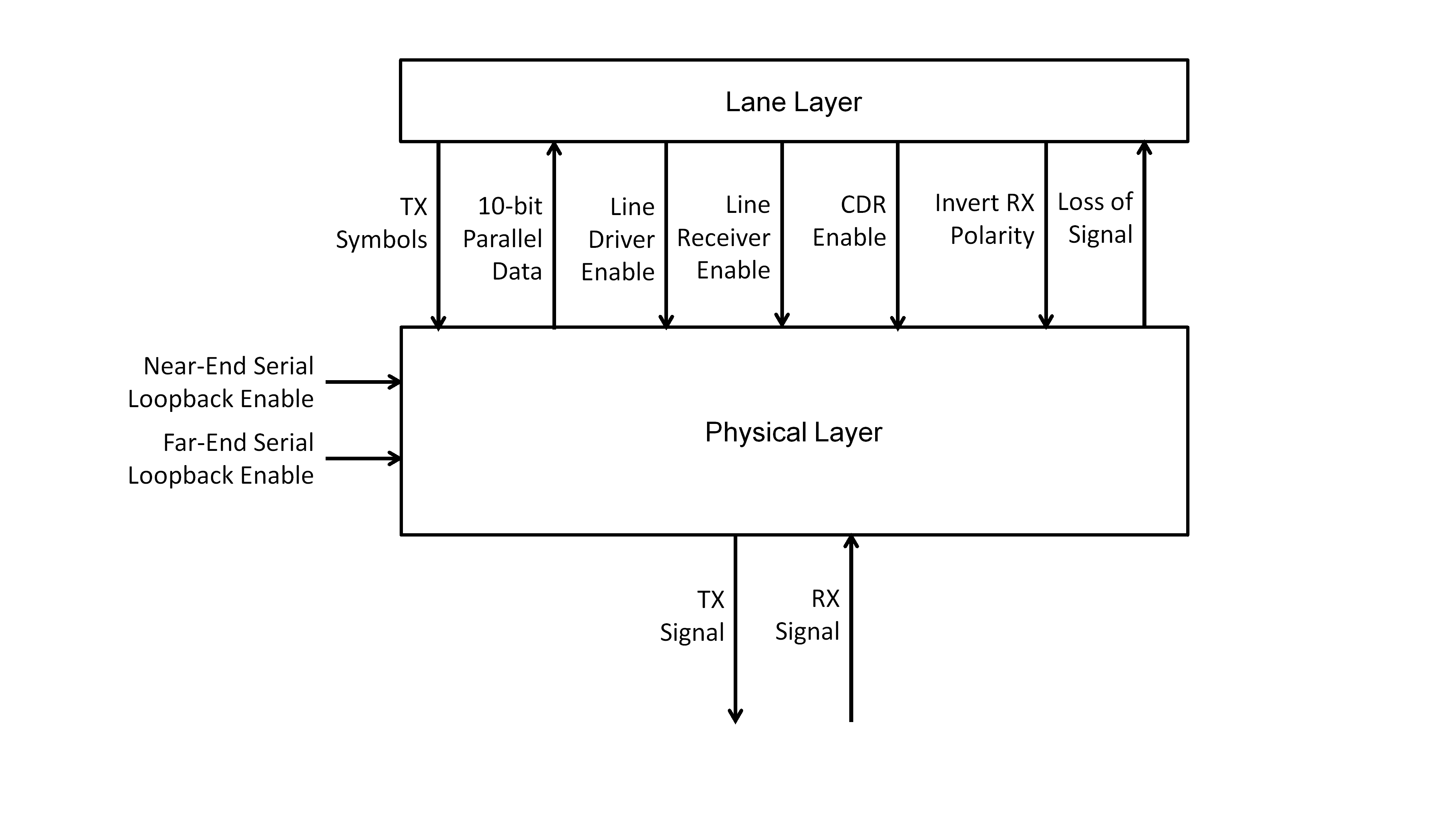 Figure 58: Interfaces to the Physical layer
Serialisation
Serialiser/deserialiser
10-bit symbols shall be transmitted serially over the physical medium.
A serialiser shall be used to convert each parallel 10-bit symbol for transmission into a serial bit stream with each bit of the symbol being sent one after the other.
One, two or four symbols are provided to the serialiser in parallel.
The least significant bit of the 10-bit symbol shall be transmitted first.
The received digital signal from the line receiver shall be sampled by a clock-data recovery circuit to recover the serial bit stream.
The clock-data recovery circuit should indicate, in a status register, when bit synchronisation is achieved.
This is for status information only.
The recovered serial bit stream shall be converted to 10-bit parallel form by a deserialiser.
The deserialiser does not necessarily produce a stream of 10-bit symbols because the boundary of the symbols is not known by the deserialiser. One, two or four sets of 10-bit parallel data are provided by the deserialiser, depending upon the implementation.
When a valid serial bit stream appears on the input of the de-serialiser, it shall be ready to start recovering data from that serial bit stream after no more than 150000 bits have been received.
- 1 This assumes that any PLL or similar circuit related to the clock-data recovery is locked.
- 2 It takes around a further 42000 bits after bit synchronization has been achieved for a lane to reach the Active state. The initialisation time-out timer is set to the time it takes to send 200000 bits (5000 words). 200000 – 42000 bits leads to the 150000 bit requirement.
When Invert RX Polarity is asserted, each bit of the 10-bit parallel output from the deserialiser shall be inverted.
It is possible to do this by inverting the serial data entering the deserialiser or inverting each bit on the output of the deserialiser.
Serial loopback
A serial loopback facility should be provided in the SpaceFibre port for test purposes.
The near-end serial loopback shall connect the bit stream output from the serialiser in the transmitter, directly into the serial input of the deserialiser in the receiver.
The far-end serial loopback shall connect the digital signal from the output of the line receiver directly to the input of the line driver.
Data signalling rates
The data signalling rate for a SpaceFibre lane shall be the same, ±0,01% in each direction of the lane.
The data signalling rate for a SpaceFibre lane shall be one of the following: 1 Gbit/s, 1,25 Gbit/s, 2 Gbit/s, 2,5 Gbit/s, 3,125 Gbit/s, 5 Gbit/s or 6,25 Gbit/s within ±0,01%.
The data signalling rate for a SpaceFibre lane may be any rate, provided that the two ends of the lane are at the same data signalling rate, ±0,01%.
A multi-lane implementation has each lane running at the same data signalling rate from the same clock or reference clock, see clause 5.6.2.
Loss of signal
When the level of the RX Signal received by the Physical layer is below the minimum threshold value of the receiver or when the transition density is below a certain value, NoSignal shall be asserted.
When a receiver does not provide a loss of signal indication, the NoSignal signal may either:
- Be always de-asserted indicating that there is always a signal present at the receiver.
- Have its value determined in some other way.
For example, the value of NoSignal can be determined by counting the number of bit transitions at the output of the receiver in a given period of time and asserting NoSignal when the bit transition density is above a suitable threshold.
Electrical physical layer
General
The electrical physical layer shall comprise a line driver, electrical cable assembly or PCB track, and line receiver.
One direction of the Physical layer is illustrated in Figure 59.
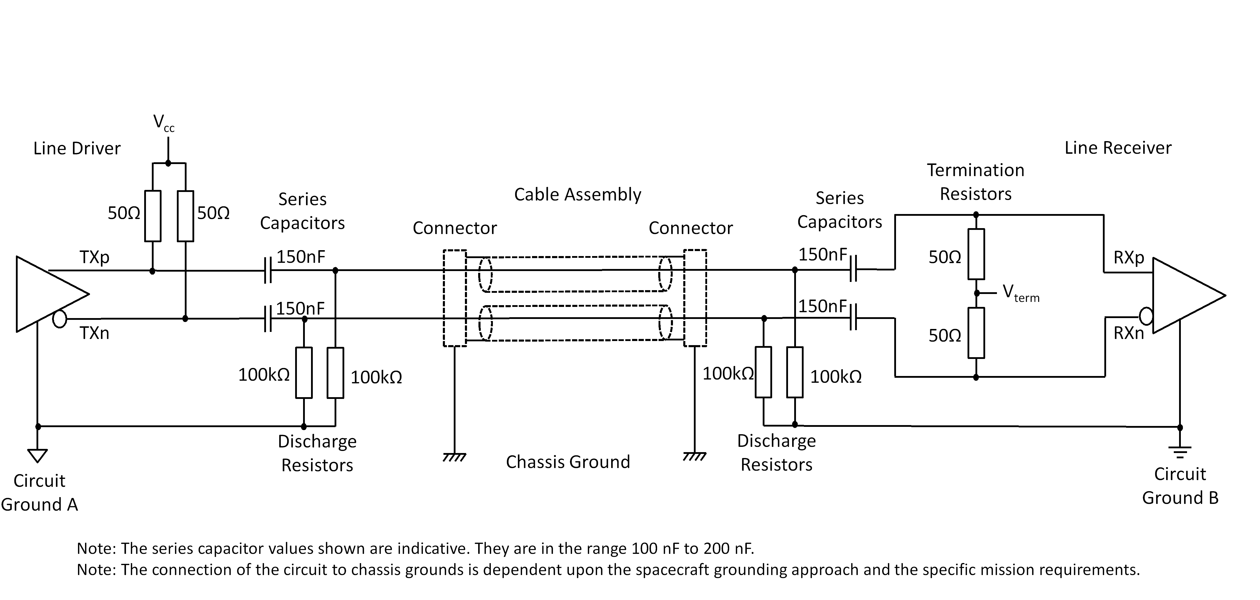 Figure 59: One direction of electrical Physical layer, showing series capacitors, discharge resistors, and different grounds
Electrical serial output
The serial output shall generate the differential signals listed in Table 513.
Table 513: Serial output interface
|
Signal
|
Function
|
|
TXp
|
Positive side of the differential serial output.
|
|
TXn
|
Negative side of the differential serial output.
|
The serial output shall be AC coupled using 100 nF to 200 nF series capacitors on both transmit signals, TXp and TXn.
AC coupling protects the driver and receiver in the event of a failure that results in a high DC voltage on the signal lines. It helps to prevent fault propagation. It also prevents DC ground loops. The serial input is also AC coupled on the input side, see clause 5.4.3.3.
If a particular SerDes requires different AC coupling capacitors, values outside the 100 nF to 200 nF range may be used.
100 kohm ±10% discharge resistors shall be connected from the connector side of the series coupling capacitors to local circuit ground on both transmit signals, TXp and TXn.
The series capacitors and discharge resistors are illustrated in Figure 59.
The serial output line driver shall use Current Mode Logic, CML.
The differential CML output signal is illustrated in Figure 510. It is possible to convert Voltage Mode Logic, VML, to CML using a resistor network. For example, see Nick Holland, “Interfacing Between LVPECL, VML, CML, and LVDS Levels”, Texas Instruments, Application Report SLLA120, December 2002.
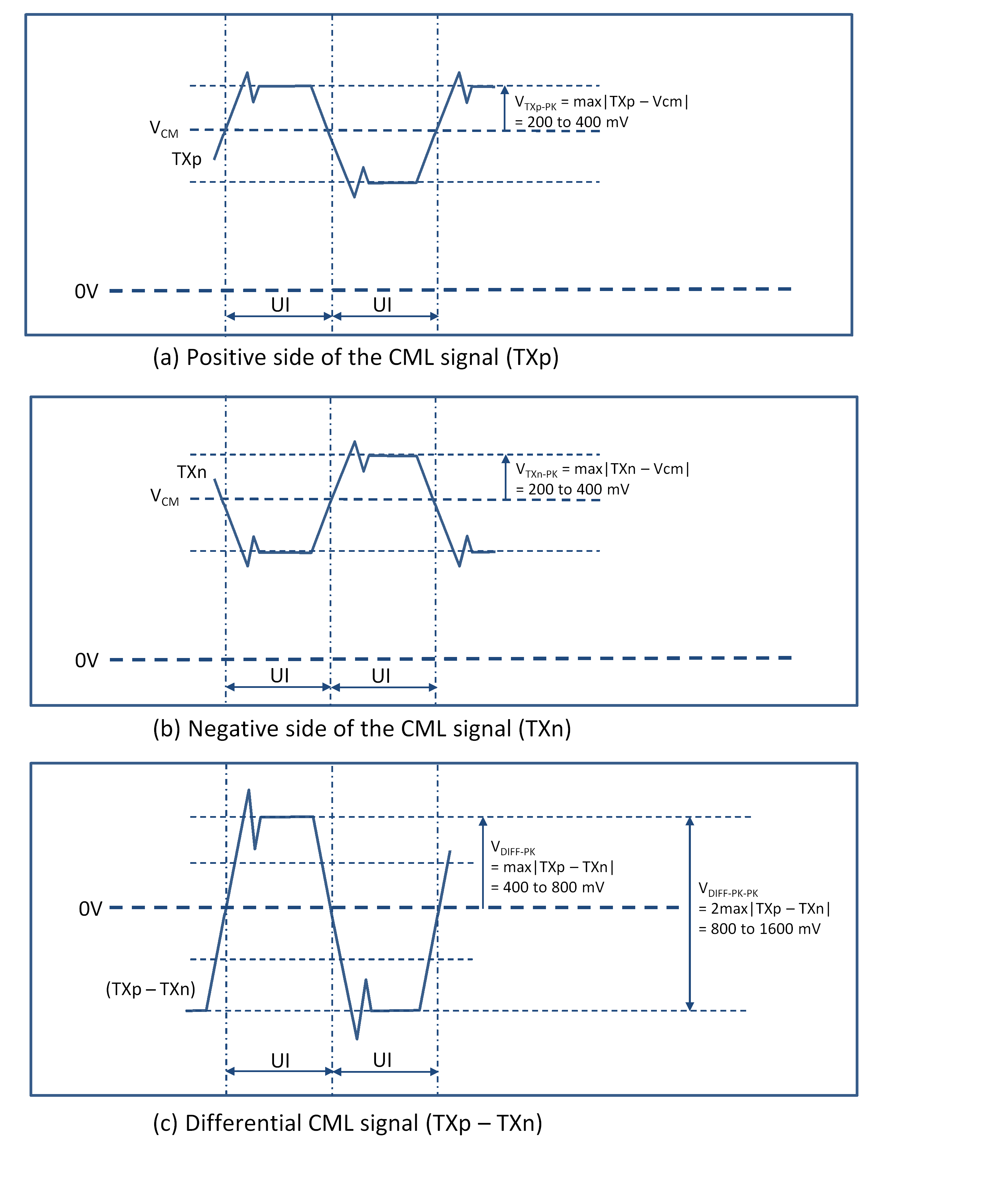 Figure 510: Serial output signals
When a SerDes serial interface in an FPGA or ASIC uses a different type of driver technology than CML, the serial output line drive may use that different technology other than CML provided that it meets the signal specifications in requirements 5.4.3.2g to 5.4.3.2k
When terminated by a pair of 50 Ω ±1 Ω termination resistors, as shown in Figure 511, and measured using a wide bandwidth oscilloscope with a combined bandwidth of at least three times the bit rate, the output signals shall conform to the following:
- Amplitude of each signal, VTXp-PK and VTXn-PK individually, of between 0,2 Volt and 0,4 Volt.
- Differential peak-to-peak amplitude, VDIFF-PK-PK, which is twice the maximum, absolute value of TXp minus TXn, of between 0,8 Volt and 1,6 Volt.
- Jitter of less than 35 % of the bit interval, Jitter ≤ ±0,175UI.
The corresponding eye pattern masks for the near-end differential signals are illustrated in Figure 512.
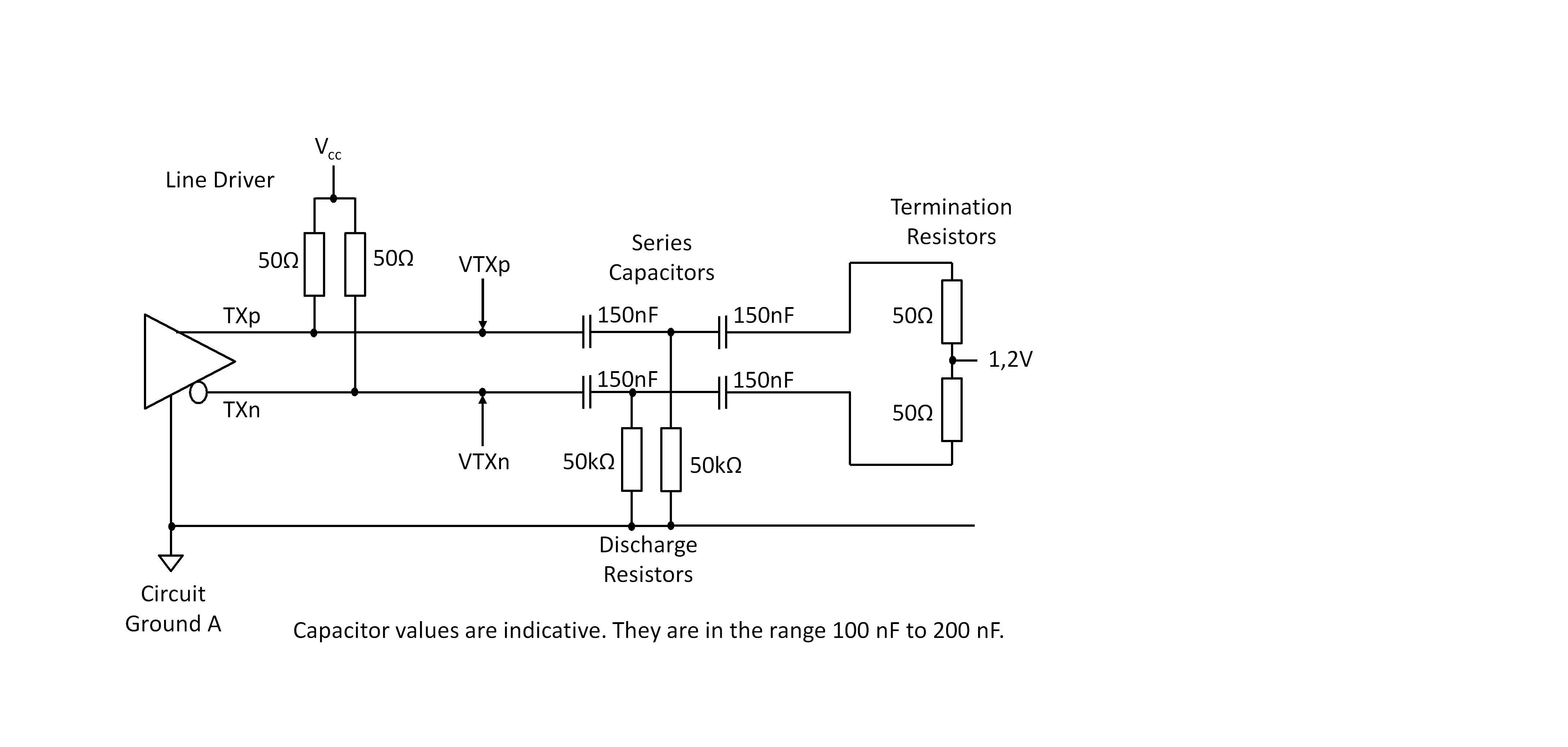 Figure 511: Serial output test circuit
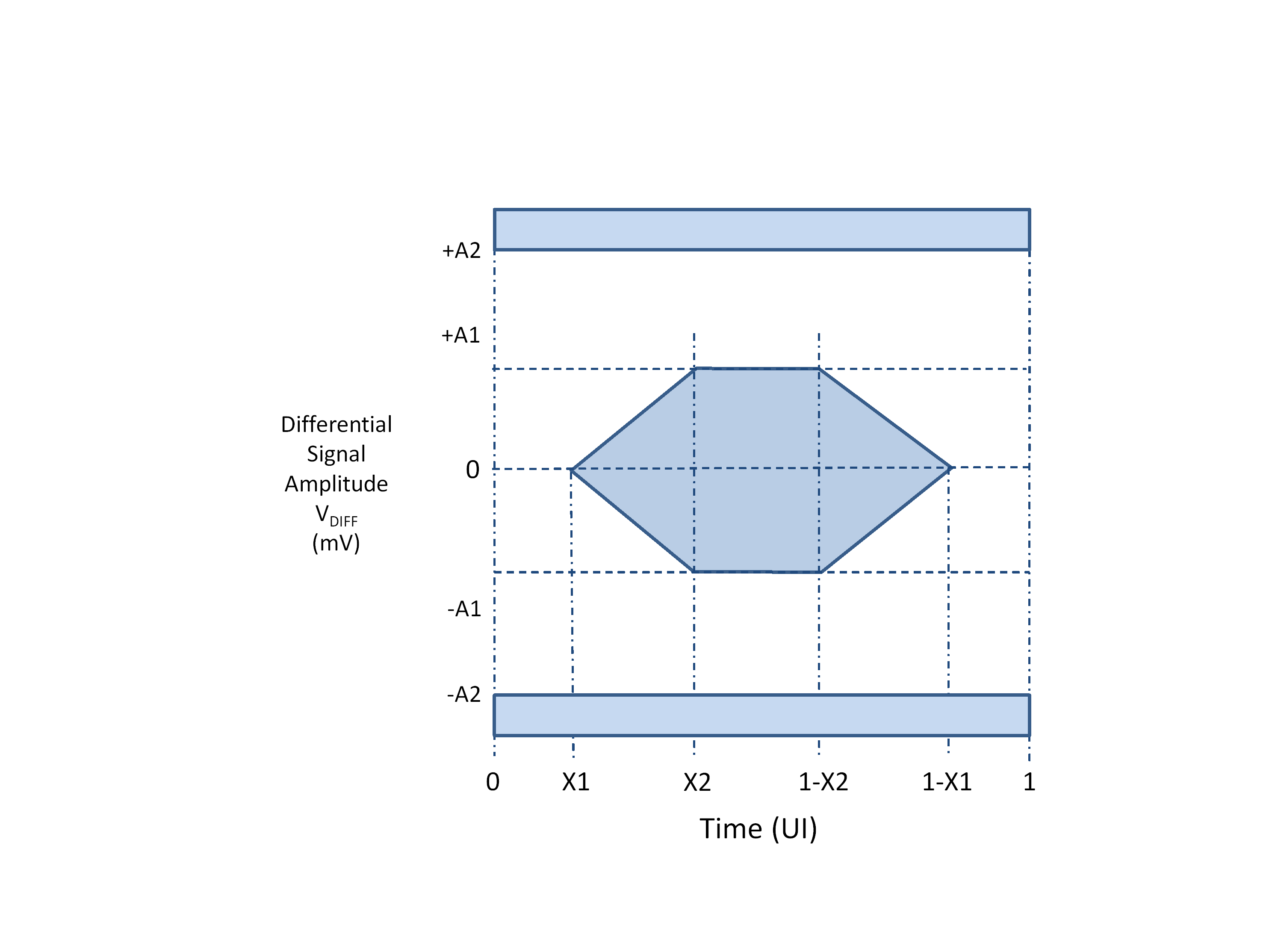 Figure 512: Serial eye pattern mask
For data signalling rates in the range 1 Gbit/s to 3,125 Gbit/s, the serial eye pattern mask shall have the intervals specified in Table 514.
The near-end values are measured at the transmitter outputs and the far-end values are measured at the receiver inputs.
Table 514: Serial eye pattern mask intervals 1 Gbit/s to 3,125 Gbit/s
|
Symbol
|
Near-End Value
|
Far-End Value
|
Units
|
|
X1
|
0,175
|
0,275
|
UI
|
|
X2
|
0,390
|
0,400
|
UI
|
|
A1
|
400
|
100
|
mV
|
|
A2
|
800
|
800
|
mV
|
For data signalling rates in the range above 3,125 Gbit/s to 6,25 Gbit/s, the serial eye pattern mask shall have the intervals specified in Table 515.
When operating between 3,125 Gbit/s and 6,125 Gbit/s and the receiver has a lower input threshold voltage, the far-end value of A1 may be 50 mV.
This allows greater distances to be covered using electrical media, when the receiver is capable of detecting smaller signals.
Table 515: Serial eye pattern mask intervals above 3,125 Gbit/s to 6,25 Gbit/s
|
Symbol
|
Near-End Value
|
Far-End Value
|
Units
|
|
X1
|
0,165
|
0,3
|
UI
|
|
X2
|
0,4
|
0,5
|
UI
|
|
A1
|
400
|
100
|
mV
|
|
A2
|
800
|
800
|
mV
|
The driver characteristics shall have the values listed in Table 517 and Table 518.
Jitter is specified in terms of total jitter (TJ) and deterministic jitter (DJ). The random component of the jitter can be determined and related to the required BER using the following formulae and Table 516.
Jp-p = 2Jm-p
where: Jp-p is the peak to peak jitter and Jm-p is the mean to peak jitter.
TJp-p ≤ DJp-p – RJp-p
RJp-p = αRJrms
where α is given by
Values of α are tabulated for various BER in Table 516.
For further information refer to the following application notes from Maxim Integrated: HFAN-4.0.2, HFAN-4.0.3 and HFAN-4.0.4.
Table 516: Coefficient α for different values of BER
|
BER
|
α
|
|
10-5
|
8.530
|
|
10-6
|
9.507
|
|
10-7
|
10.399
|
|
10-8
|
11.224
|
|
10-9
|
11.996
|
|
10-10
|
12.723
|
|
10-11
|
13.412
|
|
10-12
|
14.069
|
|
10-13
|
14.698
|
|
10-14
|
15.301
|
|
10-15
|
15.883
|
|
10-16
|
16.444
|
Pre-emphasis or de-emphasis of the differential transmit signals may be used, when the transmitter supports them.
Pre-emphasis compensates for the “RC” effect of a cable in the transmitter, opening the eye pattern at the receiver. De-emphasis reduces the signal level of subsequent bits which have the same value as the current bit. De-emphasis reduces inter-symbol interference.
Table 517: Driver and receiver characteristics 1 Gbit/s to 3,125 Gbit/s
|
Parameter
|
Value
|
Comment
|
|
Bit rate
|
1 Gbit/s ± 0,01%
|
These are the standard bit rates. Other bit rates in the range 1 Gbit/s to 3,125 Gbit/s are possible
|
|
Unit Interval
|
1000 ps
|
1 Gbit/s
|
|
Output Amplitude Differential Peak-to-Peak
|
1600 mV max
|
|
|
Input Threshold Differential
|
±100 mV max
|
The specific threshold is dependent on the SerDes being used.
|
|
Load
|
80 to 120 ohm
|
100 ohm nominal
|
|
Jitter
|
≤ ±0,175 UI peak from mean
|
The total jitter figure is for a BER of 10-12, i.e. with this level of jitter, a BER of10-12 can be expected. |
|
Signal coupling
|
AC
|
100-200 nF capacitor at the near-end and at the far-end.
|
|
Differential input return loss
|
≥ 10 dB
|
100 ohm reference
|
|
Common mode input return loss
|
≥ 6 dB
|
25 ohm reference
|
Table 518: Driver and receiver characteristics above 3,125 Gbit/s to 6,25 Gbit/s
|
Parameter
|
Value
|
Comment
|
|
Bit rate
|
4 Gbit/s ± 0,01%
|
These are the standard bit rates. Other bit rates are possible.
|
|
Unit Interval
|
250 ps
|
4 Gbit/s
|
|
Output Amplitude Differential Peak-to-Peak
|
1600 mV max
|
|
|
Input Threshold Differential
|
±100 mV max
|
The specific threshold is dependent on the SerDes being used.
|
|
Load
|
80 to 120 ohm
|
100 ohm nominal
|
|
Output Jitter
|
≤ ±0,165 UI peak from mean
|
The total jitter figure is for a BER 10-12 i.e. with this level of jitter a BER 10-12 can be expected. |
|
Signal coupling
|
AC
|
100-200 nF capacitor at the near-end and at the far-end.
|
|
Differential input return loss
|
≥ 8 dB
|
100 ohm reference
|
|
Common mode input return loss
|
≥ 6 dB
|
25 ohm reference
|
A positive differential signal at the output of the line driver, VTXp > VTXn, shall be used to transmit a logic 1.
A negative differential signal at the output of the line driver, VTXp < VTXn, shall be used to transmit a logic 0.
The line driver shall be operational when the line driver enable signal is asserted.
When the line driver supports a low-power, non-operational state, the line driver shall enter the low-power, non-operational state when the line driver enable signal is de-asserted.
Electrical serial input
The serial input shall accept the differential signals listed in Table 519.
Table 519: Serial input interface
|
Signal
|
Function
|
|
RXp
|
Positive side of the differential serial input.
|
|
RXn
|
Negative side of the differential serial input.
|
The receiver characteristics shall have the values listed in Table 517 and Table 518.
The serial input shall be AC coupled using 100 nF to 200 nF series capacitors on both the receive signals, RXp and RXn.
AC coupling protects the driver and receiver in the event of a failure that results in a high DC voltage on the signal lines. It helps to prevent fault propagation. It also prevents DC ground loops. The serial output is also AC coupled on the output side, see clause 5.4.3.2.
If a particular SerDes requires different AC coupling capacitors, values outside the 100 nF to 200 nF range may be used.
100 kohm ±10% discharge resistors shall be connected from the connector side of the series coupling capacitors to local circuit ground on both receive signals, RXp and RXn.
Each half of the serial input differential signal shall be terminated by a 50 ohm ±20 % impedance to a termination voltage of 0 Volt to 2,5 Volt.
- 1 The limitation of the termination voltage is to prevent a high voltage spike on the line when the unit is switched on/off. In practice the termination voltage is determined by the receiver circuit.
- 2 This is illustrated in Figure 59.
An equivalent form of termination of the input signal may be used, when needed by a particular receiver device.
For example, see Nick Holland, “Interfacing Between LVPECL, VML, CML, and LVDS Levels”, Texas Instruments, Application Report SLLA120, December 2002.
Post-emphasis of the differential receive signals may be used, when the receiver supports post-emphasis.
Post-emphasis compensates for the low-pass characteristics of the cable in the receiver, opening the eye pattern at the receiver.
A differential signal (RXp – RXn) greater than +100 mV shall result in logic 1 at the line receiver output.
The differential receive signal and its components are illustrated in Figure 513.
A differential signal (RXp – RXn) less than -100 mV shall result in logic 0 at the receiver output.
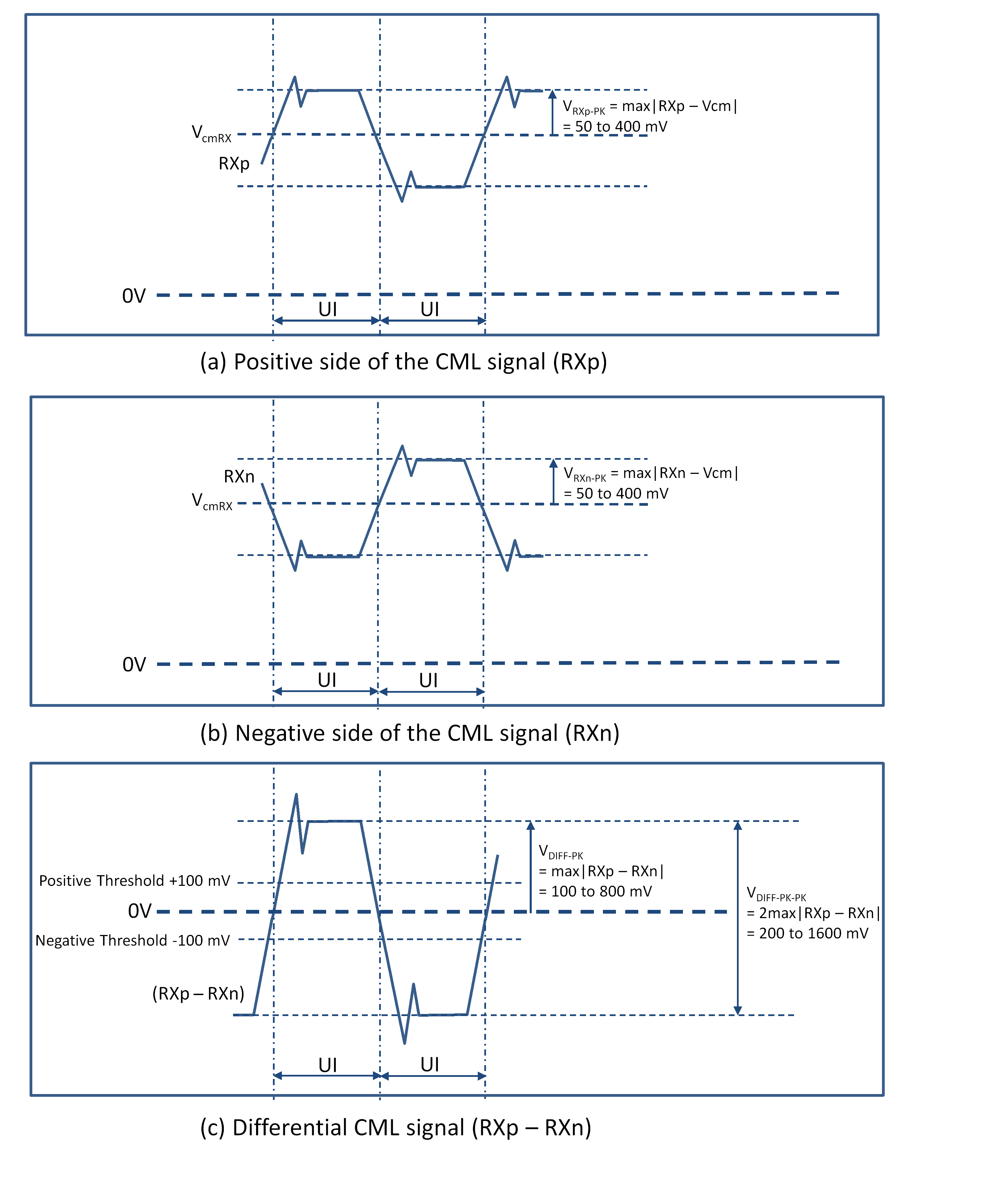 Figure 513: Serial input signals
A differential signal that does not meet the ±100 mV minimum input differential voltage may be used, provided that the received differential voltage is sufficient for the receiver and the maximum signal level at the receiver is not greater than the receiver can tolerate.
TLK2711-SP has a min differential signal of 220 mV and a maximum of 1600 mV. This equates to ±220 mV threshold and a maximum signal level of ±1600 mV.
When measured at the inputs to the line receiver using a wide bandwidth oscilloscope with differential probes and a combined bandwidth of at least three times the bit rate, the receiver shall operate correctly under the far-end conditions listed in Table 514 and Table 515.
The differential signal requirements for the receiver are illustrated in the eye pattern mask of Figure 512.
When access to the inputs of the line receiver is restricted, the receive eye pattern may be measured within 1 cm of the receiver pins on the integrated circuit or further away provided that compensation for the signal difference between the measurement point and the receiver inputs is applied.
The receiver shall have a differential return loss of more than 10 dB from 100 MHz to the maximum operating frequency of the link.
The maximum operating frequency of a link is half the bit rate, i.e. a 3,125 Gbit/s link has a maximum operating frequency of 1,5625 GHz.
The receiver shall have a common mode return loss of more than 6 dB from 100 MHz to the maximum operating frequency of the link.
The line receiver shall be operational when the line receiver enable signal is asserted.
When the line receiver supports a low-power, non-operational state, the line receiver shall enter the low-power, non-operational state when the line receiver enable signal is de-asserted.
Electrical serial lane budget
The SpaceFibre electrical connection from line driver to line receiver, including PCB traces, connectors and cable assemblies, shall have an insertion loss of less than 12 dB, at three times the frequency corresponding to the maximum specified operating bit rate.
- 1 This corresponds to the minimum transmit signal level of ±400 mV being reduced to the minimum acceptable signal level at the receiver, ±100 mV. The frequency corresponding to a maximum specified bit rate of 5 Gbit/s is 2,5 GHz.
- 2 A insertion loss of 12 dB results in a maximum cable length of 3,6 m, using Type-B connectors and cable assemblies as defined in clause 5.4.4.4.
When a line driver provides a higher signal level, the acceptable insertion loss may be higher than 12 dB.
Electrical medium
General
The differential characteristic impedance of the electrical medium shall be 100 ohm ±10% from 100 MHz to twice the frequency corresponding to the maximum bit rate.
If the bit rate is 3,125 Gbit/s, the frequency corresponding to this is 1,5625 GHz and twice this frequency is 3,125 GHz.
PCB tracks
The PCB tracks for electrical SpaceFibre shall be 100 ohm ±10 ohm differential impedance.
Two pairs of differential PCB tracks shall be used for a bi-directional SpaceFibre lane, one pair for each direction.
Type-A flight electrical medium
Type-A flight electrical connectors
For flight equipment and cable assemblies, Type-A connections conforming to ESCC Specification 3409/001 shall be used.
Male two-way connectors shall conform to ESCC 3409/001 variant 10.
A two-way connector has two pairs of contacts, one pair for each direction, and a total of four contacts.
Female two-way connectors shall conform to ESCC 3409/001 variant 11.
Female two-way PCB panel mounting connectors shall conform to ESCC Specification ESCC 3401/090 variant 7.
Type-A flight cable
Flight cable shall be coaxial cable that conforms to the cable specification in ESCC Generic Specification 3409 and ESCC Detailed Specification 3409/001.
Type-A flight cable assemblies
Male two-way connectors conforming to clause 5.4.4.3.1 shall be used on flight cable assemblies.
The flight cable assembly shall use the coaxial cable specified in clause 5.4.4.5.2.
The connector contacts for Type-A flight cable assemblies shall be terminated as shown in Table 520.
This is illustrated in Figure 514.
The length of the coaxial cables used in the flight cable assembly shall be of the same length within ±2 mm.
Table 520: Type-A electrical flight cable assembly connector contact terminations
|
Signal at A end
|
Pin at A end
|
Connections
|
Pin at B end
|
Signal at B end
|
|
A-TXp
|
1
|
Coaxial (i) Signal Wire
|
4
|
B-RXp
|
|
A-TXn
|
2
|
Coaxial (ii) Signal Wire
|
3
|
B-RXn
|
|
A-RXn
|
3
|
Coaxial (iii) Signal Wire
|
2
|
B-TXn
|
|
A-RXp
|
4
|
Coaxial (iv) Signal Wire
|
1
|
B-TXp
|
|
A-braids, shields of the 4 signal wires
|
Shell
|
Coaxial Shields
|
Shell
|
B-braids, shields of the 4 signal wires
|
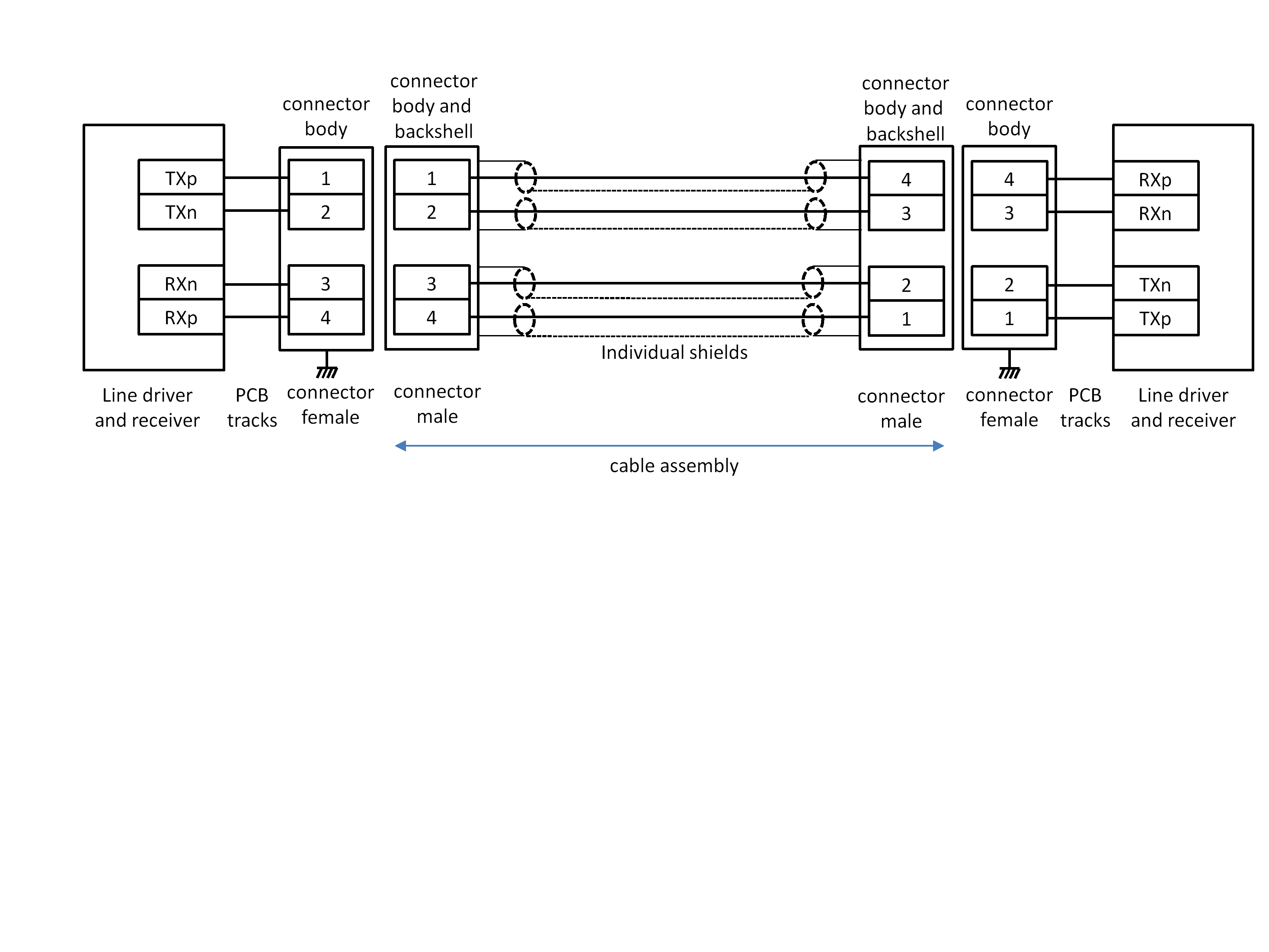 Figure 514: Type-A electrical flight cable assembly
Type-A flight connector savers
One male two-way connector and one female two-way connector conforming to clause 5.4.4.3.1 shall be used on flight connector savers.
The flight connector saver shall use the coaxial cable specified in clause 5.4.4.3.2 to wire between the connectors.
The connector contacts for Type-A flight connector savers shall be terminated as shown in Table 521.
This is illustrated in Figure 515.
The length of the coaxial cables used in the flight connector saver shall be of the same length within ±1 mm and of maximum length 100 mm.
Table 521: Type-A electrical flight connector saver connector contact terminations
|
Signal at A end
|
Pin at A end
|
Connections
|
Pin at B end
|
Signal at B end
|
|
A-TXp
|
1
|
Coaxial (i) Signal Wire
|
1
|
B-TXp
|
|
A-TXn
|
2
|
Coaxial (ii) Signal Wire
|
2
|
B-TXn
|
|
A-RXn
|
3
|
Coaxial (iii) Signal Wire
|
3
|
B-RXn
|
|
A-RXp
|
4
|
Coaxial (iv) Signal Wire
|
4
|
B-RXp
|
|
A-braids, shields of the 4 signal wires
|
Shell
|
Coaxial Shields
|
Shell
|
B-braids, shields of the 4 signal wires
|
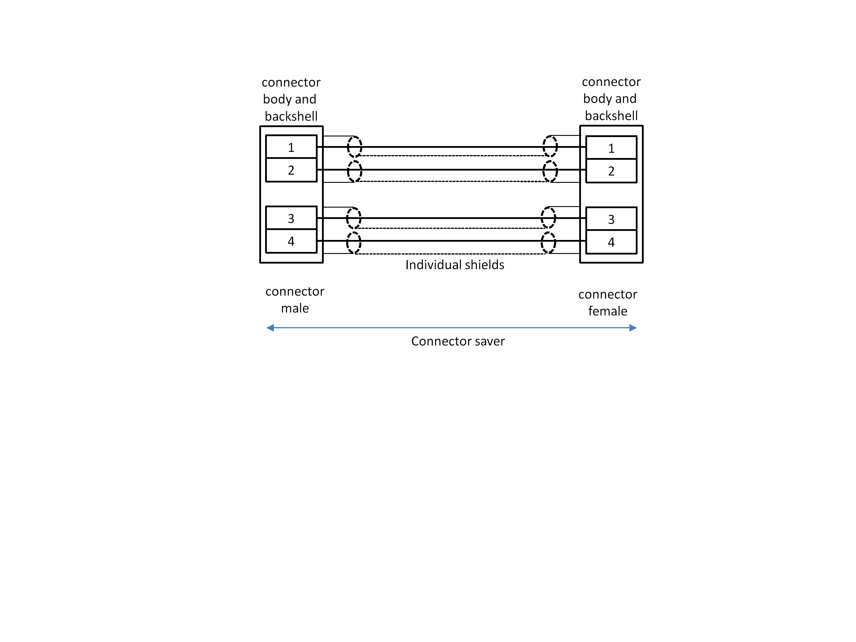 Figure 515: Type-A electrical flight connector saver
Type-B flight electrical medium
General
Type-B flight electrical medium from and including the Type-B connector at one end of a lane to and including the Type-B connector at the other end of that lane, shall:
- Maintain a signal path of 50 ohm ±5 ohm single-ended impedance or 100 ohm ±10 ohm differential impedance.
- Have an insertion loss of less than 2,2 dB/m plus 2 dB per connector pair at a maximum operating bit rate specified for the SpaceFibre electrical medium.
- Have a return loss of more than 10 dB.
- Have a near-end crosstalk isolation of better than 35 dB.
- Have a far-end crosstalk isolation of better than 35 dB.
- Have a signal skew between TXp and TXn, measured at the receiving end of a lane, of less than the larger of:
- ±20 ps.
- ±10 % of the shortest bit interval that the medium is used for.
±20 ps corresponds to a difference in path length of around ±2 mm. 10 Gbit/s = 100 ps bit time, which is around 15 mm signal length. 10 % of this length is 1,5 mm which is difficult to manufacture.
A specific Type-B flight electrical medium shall be referred to by a unique descriptive name based on the type of connector used in the following format: SpFi-TypeB-Connector, where Connector is the name or type of the connector.
For example, a Type-B flight electrical medium using SMA connectors has the name SpFi-TypeB-SMA.
Type-B flight electrical connectors
Type-B flight electrical connectors shall be of matched impedance of either of the following:
- 50 ohm ±5 ohm single–ended impedance, for single signal contacts.
- 100 ohm ±10 ohm differential impedance, for differential signal contacts.
Male connectors shall be used for Type-B cable assemblies.
Female connectors shall be used for Type-B EGSE to flight adaptor cable assemblies.
Female PCB panel mounting connectors or female PCB mounting connectors shall be used for connecting to a PCB.
Type-B flight cable
Type-B flight cable shall be either
- 50 ohm ± 5 ohm single–ended impedance.
- 100 ohm ± 10 ohm differential impedance.
Cable with single-ended impedance is cable with a single signal conductor and shield, such as coaxial cable. Two of these cables make a differential pair. Cable with differential impedance is cable with signal wires arranged in pairs, such as twisted pair or twin-axial cable.
Flight cable shall contain one or several signal wires or pairs of signal wires with individual shields or an overall shield or both individual and overall shields.
Type-B flight cable assemblies
Type-B flight cable assemblies shall carry the following four signals: TXp, TXn, RXp, RXn, for each lane supported by the cable assembly.
Type-B flight cable assemblies shall carry one or more lanes.
Male connectors conforming to clause 5.4.4.4.2 shall be used on Type-B flight cable assemblies.
When a Type-B flight cable assembly has the same kind of connector at each end, that cable assembly should be referred to by a unique name in the following format: SpFi-TypeB-Connector where Connector is the kind of connector used at each end of the cable assembly.
A cable assembly using SMA connectors is referred to as SpFi-TypeB-SMA.
A Type-B flight cable assembly may use different kinds of connector at each end of the cable assembly.
When Type-B flight cable assembly has different kinds of connector at each end, that cable assembly should be referred to by a unique name in the following format: SpFi-TypeB-ConnectorA-ConnectorB, where ConnectorA is the kind of connector used at one end of the cable assembly and ConnectorB is the kind of connector used at the other end of the cable assembly.
A cable assembly using SMA connectors at one end and a 38999 connector at the other end is referred to as SpFi-TypeB-SMA-38999.
The Type-B flight cable assembly shall use the cable specified in clause 5.4.4.4.3.
The connector contacts for each lane of a Type-B flight cable assembly shall be terminated as shown in Table 522.
The length of the coaxial cables used in the Type-B flight cable assembly shall be of the same length within ±2 mm.
Table 522: Type-B electrical flight cable assembly connector contact terminations
|
Signal at A end
|
Connections
|
Signal at B end
|
|
A-TXp
|
Signal Wire (i)
|
B-RXp
|
|
A-TXn
|
Signal Wire (ii)
|
B-RXn
|
|
A-RXp
|
Signal Wire (iii)
|
B-TXp
|
|
A-RXn
|
Signal Wire (iv)
|
B-TXn
|
|
Connector Shell
|
Shields
|
Connector Shell
|
Type-C EGSE electrical medium
Type-C EGSE electrical connectors
For electrical ground support equipment, EGSE, external serial ATA connectors shall be used as specified in Serial ATA Revision 3.0:2009, clause 6.5.1.
Type-C EGSE cable
For electrical ground support equipment, EGSE, external serial ATA cable shall be used, as specified in Serial ATA Revision 3.0:2009, clause 6.6.1.
Type-C EGSE cable assemblies
For electrical ground support equipment, EGSE, a crossover external serial ATA cable shall be used.
The EGSE cable assembly shall be terminated at each end by an External Serial ATA cable receptacle as specified in Serial ATA Revision 3.0:2009, clause 6.5.1 and Figure 93 of the specification.
The EGSE cable assembly shall use the external serial ATA cable specified clause 5.4.4.5.2.
The connector contacts for Type-C EGSE cable assemblies shall be terminated as shown in Table 523.
This is illustrated in Figure 516.
Table 523: Type-C electrical EGSE cable assembly connector contact terminations
|
Signal at A end
|
Pin at A end
|
Connections
|
Pin at B end
|
Signal at B end
|
|
GND
|
1
|
Shields Pairs 1 & 2
|
7
|
GND
|
|
A-TXp
|
2
|
Pair 1 Signal Wire (i)
|
6
|
B-RXp
|
|
A-TXn
|
3
|
Pair 1 Signal Wire (ii)
|
5
|
B-RXn
|
|
GND
|
4
|
Shields Pairs 1 & 2
|
4
|
GND
|
|
A-RXn
|
5
|
Pair 2 Signal Wire (i)
|
3
|
B-TXn
|
|
A-RXp
|
6
|
Pair 2 Signal Wire (ii)
|
2
|
B-TXp
|
|
GND
|
7
|
Shields Pairs 1 & 2
|
1
|
GND
|
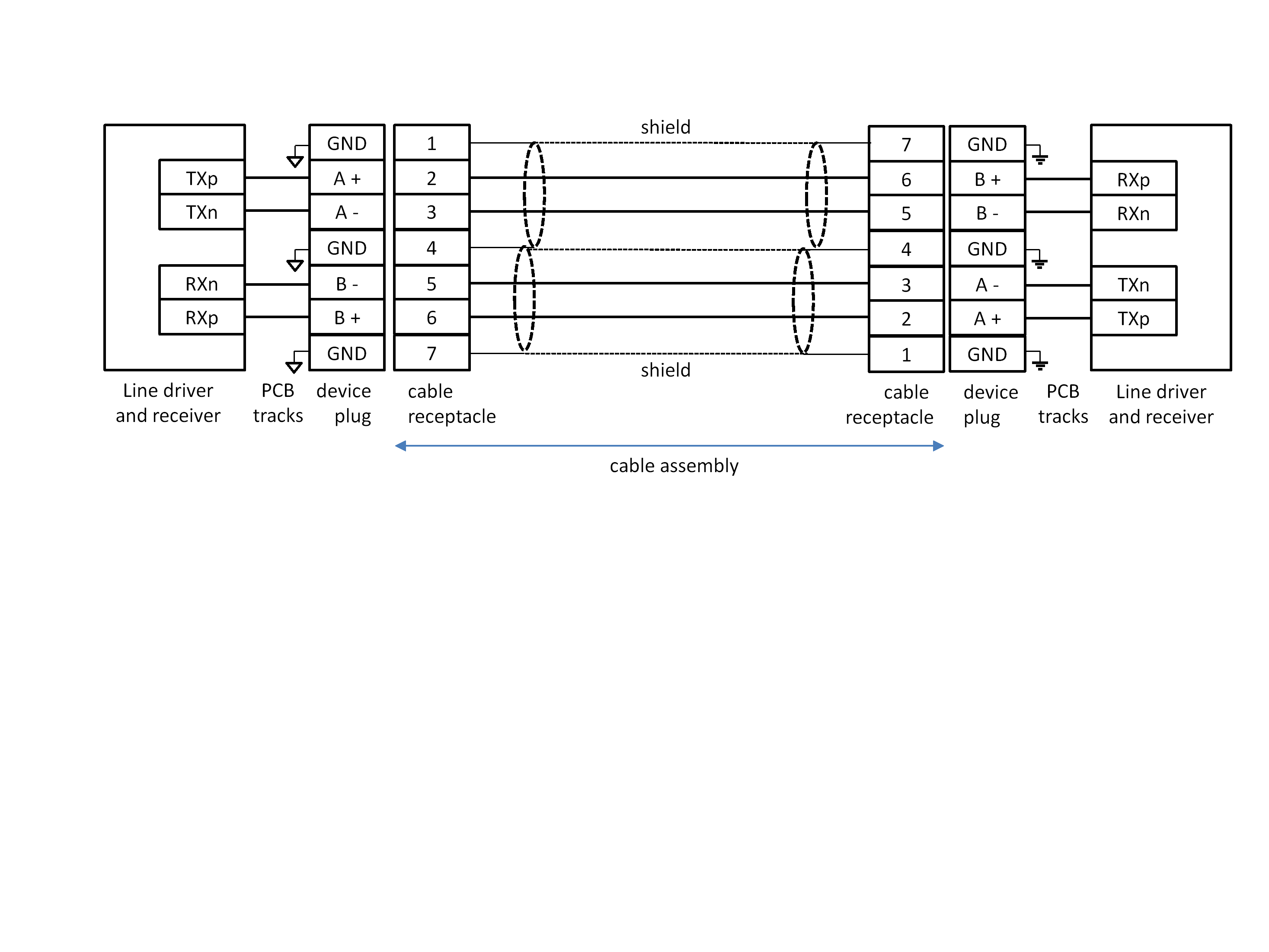 Figure 516: Type-C electrical EGSE cable assembly
Type-C EGSE to flight adaptor cable assemblies
The EGSE to flight adaptor cable assembly shall allow a SpaceFibre EGSE unit to connect to a flight cable assembly.
One end of the EGSE to flight adaptor cable assembly shall be terminated by an External Serial ATA cable receptacle as specified in Serial ATA Revision 3.0:2009, clause 6.5.1 and Figure 93 of that specification.
The other end of the EGSE to flight adaptor cable assembly shall be terminated by a female 2-way connector conforming to clause 5.4.4.3.1.
The EGSE to flight adaptor cable assembly shall use the cable specified in clause 5.4.4.5.2
The connector contacts for Type-C EGSE to flight adaptor cable assemblies shall be terminated as shown in Table 524 and illustrated in Figure 517.
Table 524: Type-C electrical EGSE to flight adaptor cable assembly connector contact terminations
|
Signal at A end
|
Pin at A end
|
Connections
|
Pin at B end
|
Signal at B end
|
|
GND
|
1
|
Coaxial (i) Shield
|
Shell
|
|
|
A-TXp
|
2
|
Coaxial (i) Signal Wire
|
1
|
B-RXp
|
|
A-TXn
|
3
|
Coaxial (ii) Signal Wire
|
2
|
B-RXn
|
|
GND
|
4
|
Coaxial (ii) & (iii) Shields
|
Shell
|
|
|
A-RXn
|
5
|
Coaxial (iii) Signal Wire
|
3
|
B-TXn
|
|
A-RXp
|
6
|
Coaxial (iv) Signal Wire
|
4
|
B-TXp
|
|
GND
|
7
|
Coaxial (iv) Shield
|
Shell
|
|
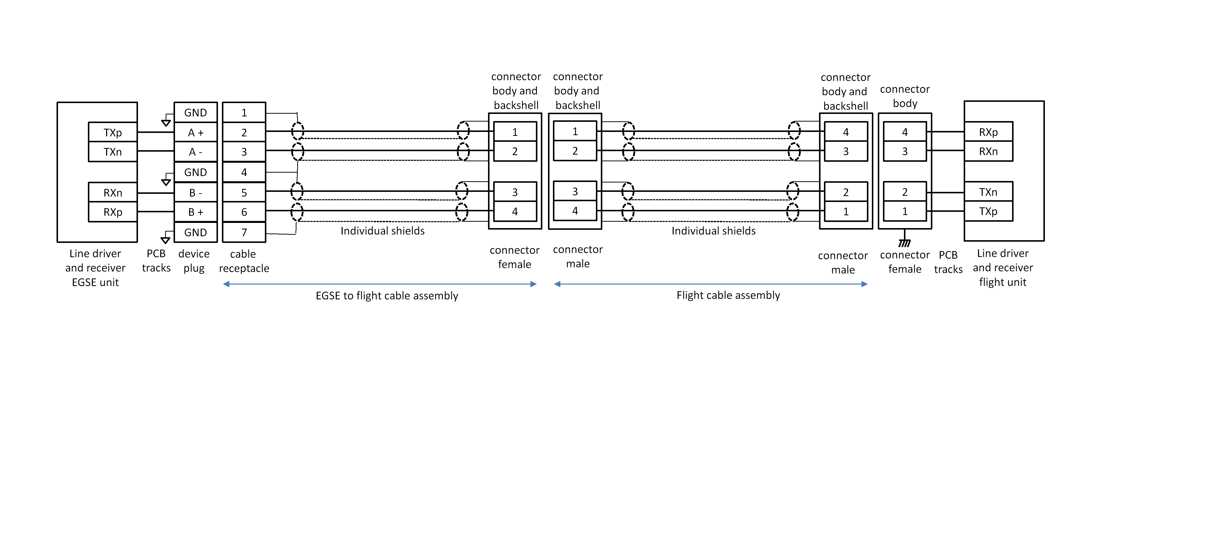 Figure 517: Type-C electrical EGSE to flight adaptor cable assembly
Type-D EGSE electrical medium
General
Type-D EGSE electrical medium from and including the Type-D connector at one end of a lane to and including the Type-D connector at the other end of that lane, shall:
- Maintain a signal path of 50 ohm ± 5 ohm single-ended impedance or 100 ohm ± 10 ohm differential impedance.
- Have an insertion loss of less than 2,2 dB/m plus 2 dB per connector pair at a maximum operating bit rate specified for the SpaceFibre electrical medium.
- Have a return loss of more than 9 dB.
- Have a near-end crosstalk isolation of better than 30 dB.
- Have a far-end crosstalk isolation of better than 30 dB.
- Have a signal skew between TXp and TXn of less than the larger of:
- ±20 ps.
- ±10% of the shortest bit interval that the medium is used for.
±20 ps corresponds to a difference in path length of around ±2 mm and is Signal skew 10 Gbit/s = 100 ps bit time, around 15 mm signal length, 10 % is 1,5 mm which is difficult to manufacture.
A specific Type-D EGSE electrical medium shall be referred to by a unique descriptive name based on the type of connector used in the following format: SpFi-TypeD-Connector, where Connector is the name or type of the connector.
For example, a Type-D EGSE electrical medium using SMA connectors has the name SpFi-TypeD-SMA.
Type-D EGSE electrical connectors
Type-D EGSE electrical connectors shall be of matched impedance of either of the following:
- 50 ohm ±5 ohm single–ended impedance, for single signal contacts.
- 100 ohm ±10 ohm differential impedance, for differential signal contacts.
Male connectors shall be used for Type-D EGSE cable assemblies.
Female connectors shall be used for Type-D EGSE to flight adaptor cable assemblies.
Female PCB panel mounting connectors or female PCB mounting connectors shall be used for connecting to a PCB.
Type-D EGSE cable
Type-D EGSE cable shall be either:
- 50 ohm ±5 ohm single–ended impedance.
- 100 ohm ±10 ohm differential impedance.
Cable with single-ended impedance is cable with a single signal conductor and shield, such as coaxial cable. Two of these cables make a differential pair. Cable with differential impedance is cable with signal arranged in pairs, such as twisted pair or twin-axial cable.
Type-D EGSE cable shall contain one or several signal wires or pairs of signal wires with individual shields or an overall shield or both individual and overall shields.
Type-D EGSE cable assemblies
Type-D EGSE cable assemblies shall carry the following four signals: TXp, TXn, RXp, RXn, for each lane supported by the cable assembly.
Type-D EGSE cable assemblies shall carry one or more lanes.
Male connectors conforming to clause 5.4.4.6.2 shall be used on Type-D EGSE cable assemblies.
When a Type-D EGSE cable assembly has the same kind of connector at each end, that cable assembly should be referred to by a unique name in the following format: SpFi-TypeD-Connector where Connector is the kind of connector used at each end of the cable assembly.
A cable assembly using SMA connectors is referred to as SpFi-TypeD-SMA.
A Type-D EGSE cable assembly may use different kinds of connector at each end of the cable assembly.
When a Type-D EGSE cable assembly has different kinds of connector at each end, that cable assembly should be referred to by a unique name in the following format: SpFi-TypeD-ConnectorA-ConnectorB, where ConnectorA is the kind of connector used at one end of the cable assembly and ConnectorB is the kind of connector used at the other end of the cable assembly.
A cable assembly using SMA connectors at one end and a 38999 connector at the other end is referred to as SpFi-TypeD-SMA-38999.
The Type-D EGSE cable assembly shall use the cable specified in clause 5.4.4.6.3.
The connector contacts for each lane of a Type-D EGSE cable assembly shall be terminated as shown in Table 525.
Table 525: Type-D electrical EGSE cable assembly connector contact terminations
|
Signal at A end
|
Connections
|
Signal at B end
|
|
A-TXp
|
Signal Wire (i)
|
B-RXp
|
|
A-TXn
|
Signal Wire (ii)
|
B-RXn
|
|
A-RXp
|
Signal Wire (iii)
|
B-TXp
|
|
A-RXn
|
Signal Wire (iv)
|
B-TXn
|
|
Connector Shell
|
Shields
|
Connector Shell
|
The lengths of the signal wires used in the Type-D EGSE cable assembly should be matched to within ±2 mm.
Fibre optic physical layer
General
The fibre optic physical layer shall comprise one of the following sets of components:
- A fibre optic transmitter, fibre optic connector, fibre optic cable assembly, connector and fibre optic receiver.
- An active optical cable with an electrical connector, fibre optic transmitter, fibre optic cable, fibre optic receiver, and electrical connector.
One direction of each of these alternatives for the fibre optic Physical layer is illustrated in Figure 518 and Figure 519.
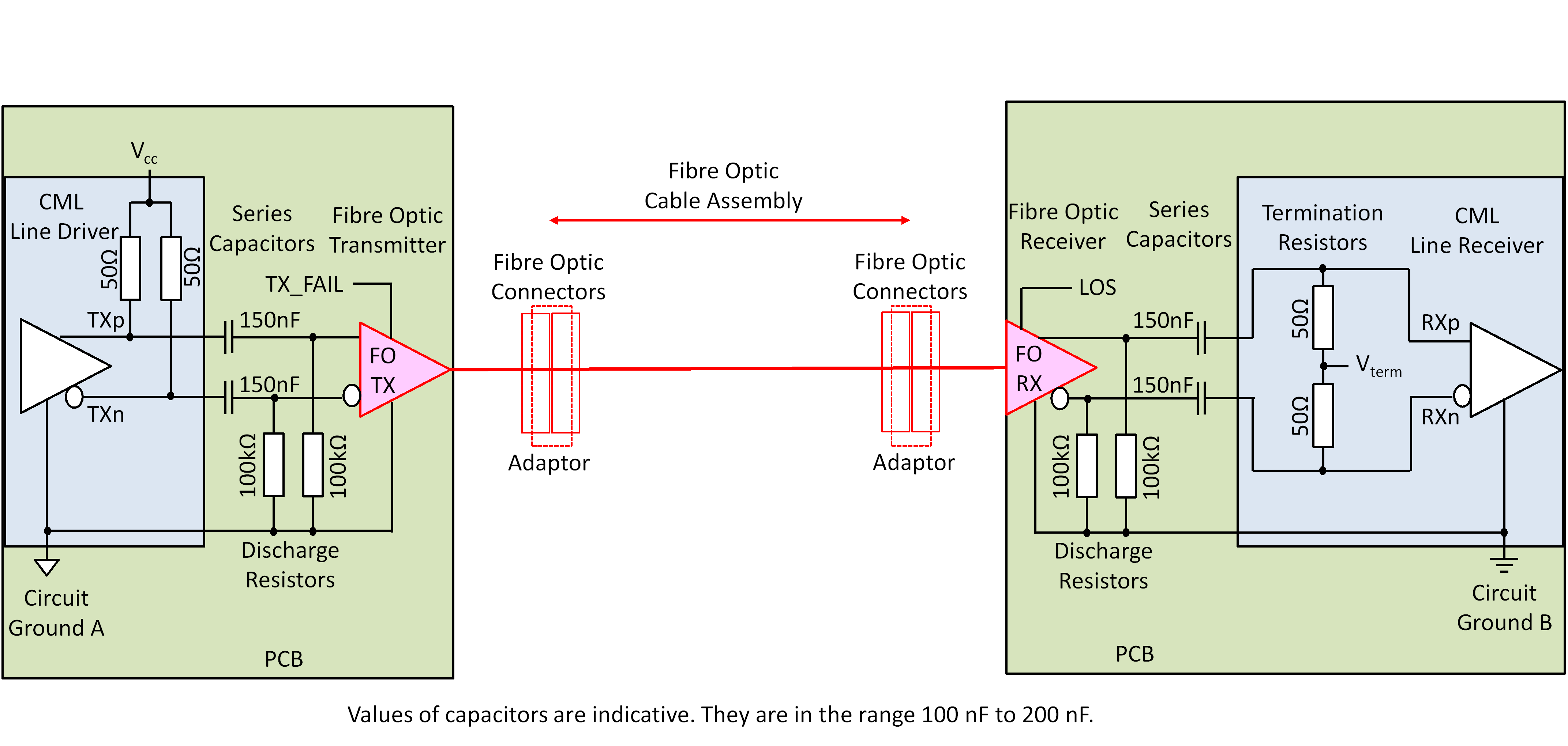 Figure 518: One direction of fibre optic Physical layer, showing fibre optic transmitter, receiver, connectors and cable
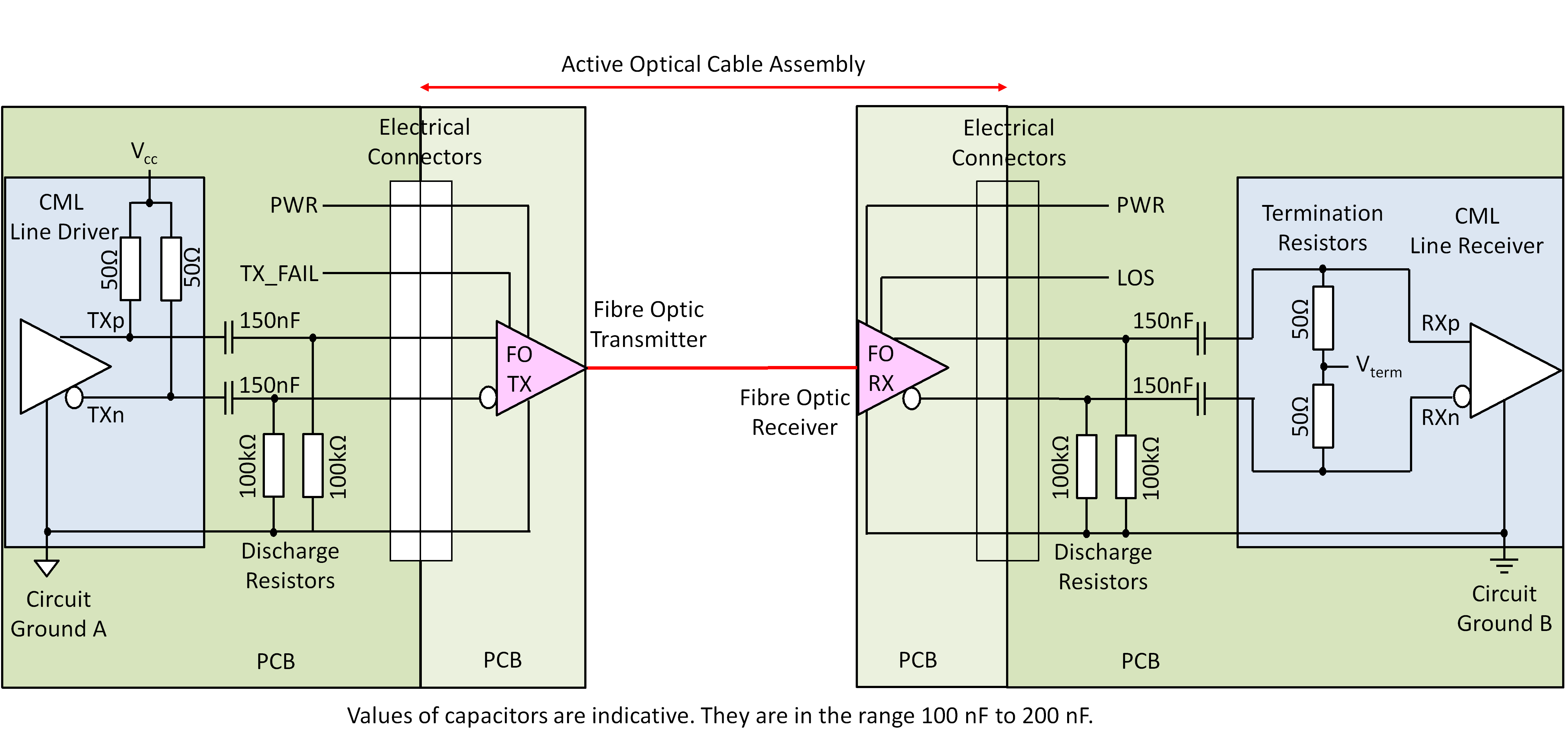 Figure 519: One direction of active optical cable type of fibre optic Physical layer
Fibre optic serial output
The fibre optic transmitter shall have CML inputs, TXp and TXn, for the serial data to be transmitted over the optical lane, as specified in clause 5.4.3.3.
The fibre optic transmitter should provide a Transmitter Failed indication, which is asserted when failure of the transmitter is detected.
This signal is useful for diagnostic purposes. It is not necessary for the operation of the SpaceFibre protocol, because a failed transmitter is detected by the receiver at the far-end of the link. Since the SpaceFibre link is bidirectional, this results in the LOST_SIGNAL control word being sent back to the near-end. The Transmitter Failed indication can be implemented using LVTTL, LVCMOS, or open drain signals, or using I2C or a similar serial control and monitoring status interface.
When a fibre optic transmitter has an I2C or similar serial control and status monitoring interface, this interface may be used to provide the Transmitter Failed indication in place of a dedicated signal.
The fibre optic transmitter shall support a nominal operating wavelength of 830 nm to 860 nm, 850 nm nominal.
Normally the fibre optic transmitter uses a VCSEL which is able to achieve the target bandwidth with an OM3 fibre. In line with current state of practice in the industry the term “Driver” is used to refer to the electrical amplifier used to drive the VCSEL, whereas “Transmitter” includes the “driver” as well as the VCSEL laser diode.
The fibre optic transmitter shall have an average output power of between 0,25 mW and 2 mW, -6 dBm to 3 dBm.
- 1 The average output power is for the 8B/10B encoding used in SpaceFibre. The values 0,25 mW and 2 mW, -6 dBm to 3 dBm, are in line with current state of practice for VCSEL-based transceivers.
The fibre optic transmitter shall support the operating data signalling rate of the link.
The bandwidth of the fibre optic transmitter shall be sufficient for sending an 8B/10B encoded signal at the operating data signalling rate.
For example, a data signalling rate of 3,125 Gbit/s requires a maximum frequency of greater than 0,7 times the data rate which is 2,2 GHz and a minimum frequency of less than 312,5 MHz. The lower operating frequency results from the fact that there is a maximum of 5 consecutive ones or 5 consecutive zeros in an 8B/10B encoded data stream. It is necessary to allow these consecutive bits to pass through the fibre optic transceiver.
The fibre optic transmitter shall tolerate an optical return loss of 12 dB without reduction in jitter performance.
The fibre optic transmitter shall have the characteristics as specified in Table 526 or Table 527. according to its operating data rate.
- 1 The corresponding eye patterns are illustrated in Figure 520 and Figure 521.
- 2 The Differential Input requirements for the fibre optic transmitter are defined in clause 5.4.3.3.
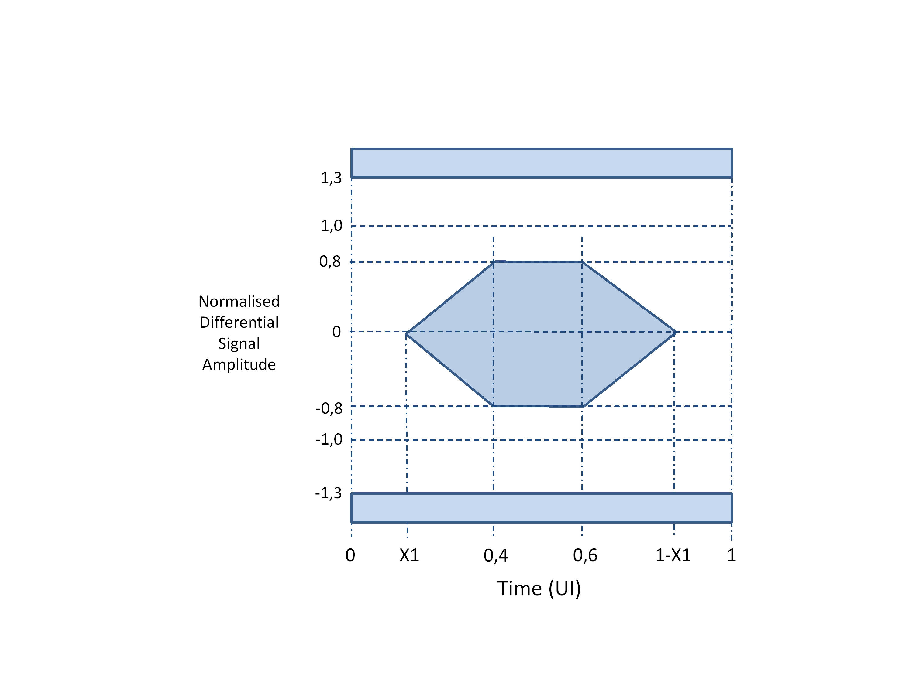 Figure 520: Electro-optical eye pattern for 1 Gbit/s to 5 Gbit/s transmitters
Table 526: Electro-optical characteristics for 1 Gbit/s to 5 Gbit/s transmitters
|
Parameter
|
Symbol
|
Min
|
Type
|
Max
|
Units
|
Note
|
|
Optical Output Power
|
POUT
|
-6,5
|
-5
|
+3
|
dBm
|
850nm VCSEL
|
|
Extinction Ratio, 1 or 1,25 Gbit/s
|
ER
|
7
|
10
|
|
dB
|
Exceeds OMA for GbE, 1FC
|
|
Extinction Ratio, 2, 2,5 and 3,125 Gbit/s
|
ER
|
5
|
|
|
dB
|
Exceeds OMA for 2FC
|
|
Extinction Ratio, 5 Gbit/s
|
ER
|
5
|
|
|
dB
|
Exceeds OMA for 4FC
|
|
Optical Wavelength
|
λOUT
|
830
|
850
|
860
|
nm
|
|
|
Spectral Width, r.m.s.
|
Δλ
|
|
|
0,85
|
nm
|
|
|
Relative Intensity Noise
|
RIN
|
|
|
-117
|
dB/Hz
|
1000BASE-S Standard (IEEE 802.3 Clause 38.3)
|
|
Transmitter Differential Input Impedance
|
Zin
|
90
|
100
|
110
|
ohm
|
AC coupled Internally
|
|
Differential Input Voltage
|
Vin_d
|
250
|
|
2200
|
mVp-p
|
CML, 100 ohm
|
|
Eye mask jitter definition, 1 and 1,25 Gbit/s
|
X1
|
|
|
0,135
|
UI p-p
|
Jp-p = 2*X1 in transmitter mask diagram.
|
|
Eye mask jitter definition, 2, 2,5 and 3,125 Gbit/s
|
X1
|
|
|
0,15
|
UI p-p
|
Jp-p = 2*X1 in transmitter mask diagram.
|
|
Eye mask jitter definition, 5 Gbit/s
|
X1
|
|
|
0,175
|
UI p-p
|
Jp-p = 2*X1 in transmitter mask diagram.
|
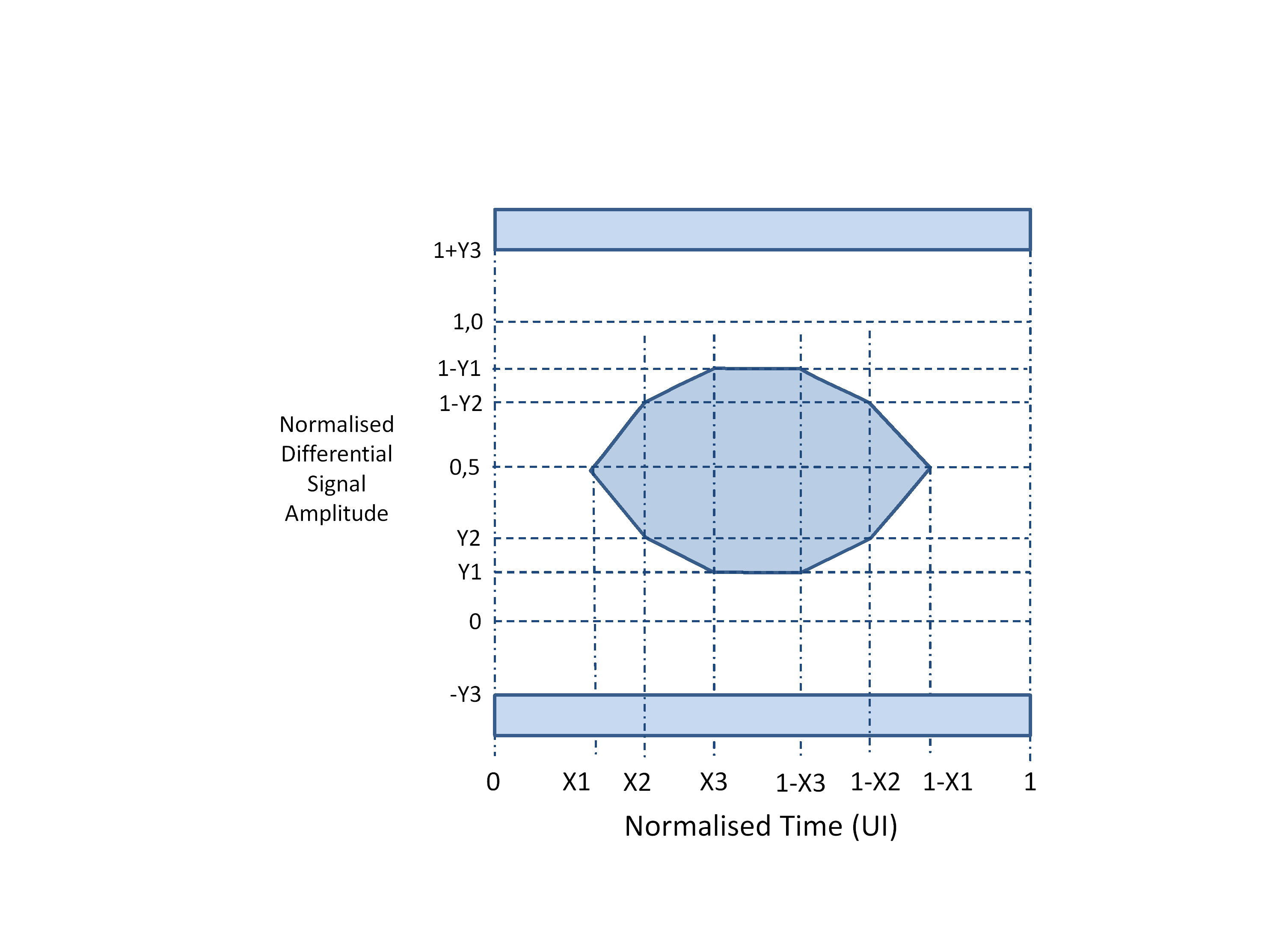 Figure 521: Electro-optical eye pattern for 1 Gbit/s to 10 Gbit/s transmitters
Table 527: Electro-optical characteristics for 1 Gbit/s to 10 Gbit/s transmitters
|
Parameter
|
Symbol
|
Min
|
Type
|
Max
|
Units
|
Notes
|
|
Optical Output Power, Avg
|
POUT
|
-5
|
|
+3
|
dBm
|
850nm VCSEL, 10GBASE-SR @ 10,3125 Gbit/s
|
|
Optical Output Power – OFF CONDITION
|
POUT-OFF
|
|
|
-30
|
dBm
|
IEEE 802.3 Clause 52.5
|
|
Optical Return Loss Tolerance
|
|
|
|
12
|
dB
|
IEEE 802.3ae Clause 52.5 Compliant
|
|
Extinction Ratio
|
Er
|
3
|
5
|
|
dB
|
IEEE802.3 Clause 52.5
|
|
Optical Wavelength
|
λOUT
|
840
|
850
|
860
|
nm
|
IEEE802.3 Clause 52.5
|
|
Spectral Width, r.m.s.
|
Δλ
|
|
|
0.4
|
nm
|
|
|
Relative Intensity Noise
|
RIN
|
|
|
-128
|
dB/Hz
|
IEEE802.3 Clause 52.5
|
|
Transmitter Differential Input Impedance
|
ZIN
|
90
|
100
|
110
|
ohm
|
AC coupled Internally
|
|
Differential Input Voltage
|
Vin_d
|
180
|
|
800
|
mVp-p
|
CML, 100 ohm
|
|
Transmitter eye mask definition
|
(X1, X2, X3, Y1, Y2, Y3)
|
|
|
(0,25, 0,40, 0,45, 0,25, 0,28, 0,40)
|
|
Actual mask values, not maximum values
|
A transmitter operating over the 1 Gbit/s to 10 Gbit/s range shall comply with 10GBASE-SR jitter and eye-mask margin at 10,3125 Gbit/s as specified in IEEE802.3 Clause 52.5.
Multi-rate transmitters operating over the range 1 Gbit/s to 10 Gbit/s, shall follow the specifications for 10 Gbit/s transmitters.
Fibre optic serial input
The fibre optic receiver shall have CML outputs, RXp and RXn, for the serial data received over the optical lane, as specified in clause 5.4.3.2.
The fibre optic receiver should provide a NoSignal indication, which is asserted when the optical signal at the receiver is at the specified level below the minimum specified receiver sensitivity level needed for reliable detection of the optical signal.
The NoSignal indication shall be de-asserted when the optical input signal level is above the specified sensitivity level of the receiver.
The NoSignal, indication can be implemented using LVTTL, LVCMOS, or open drain signals, or using I2C or a similar serial control and monitoring status interface.
When NoSignal is asserted the CML outputs of the fibre optic receiver should remain fixed at a value representing a logic 1 or logic 0, see requirement 5.4.3.2l and 5.4.3.2m.
The fibre optic receiver shall support a nominal operating wavelength of 840 nm to 860 nm, 850 nm nominal, as specified in IEEE802.3 Clause 52.5.
The fibre optic receiver shall support the operating data signalling rate of the link.
The bandwidth of the fibre optic receiver shall be sufficient for receiving an 8B/10B encoded signal at the operating data signalling rate.
The fibre optic receiver shall have a sensitivity as specified in Table 528 or Table 529 according to its operating data rate.
It is quite difficult to have one design that is truly optimized for a wide range of data rates. Table 528 provides values for individually-optimized receiver units. Note that the electrical differential output requirements for the fibre optic receiver are defined in clause 5.4.3.2.
Table 528: Electro-optical characteristics for 1 Gbit/s to 5 Gbit/s receivers
|
Parameter
|
Symbol
|
Min
|
Type
|
Max
|
Units
|
Notes
|
|
Receiver Sensitivity
|
|
|
|
|
|
|
|
Sensitivity, BER 10-12, PRBS 2-7-1, Er 10 dB
|
PIN
|
|
-22,5
|
-19
|
dBm
|
PIN PD @ 1,25 Gbit/s
|
|
Sensitivity, BER 10-12, PRBS 2-7-1, Er 10 dB
|
PIN
|
|
-22,5
|
|
dBm
|
PIN PD @ 2,5 Gbit/s
|
|
Sensitivity, BER 10-12, PRBS 2-7-1, Er 10 dB
|
PIN
|
|
-18,5
|
|
dBm
|
PIN PD @ 3,2 Gbit/s
|
|
Sensitivity, BER 10-12, PRBS 2-7-1, Er 10 dB
|
PIN
|
|
-18
|
|
dBm
|
PIN PD @ 4,25Gbit/s
|
|
Sensitivity, BER 10-12, PRBS 2-7-1, Er 10 dB
|
PIN
|
|
-17,5
|
-16
|
dBm
|
PIN PD @ 5 Gbit/s
|
|
Overload, BER 10-12, PRBS 2-7-1
|
PIN
|
-1
|
|
|
dBm
|
@1,25Gbit/s or @ 5 Gbit/s
|
|
Optical Wavelength
|
λIN
|
770
|
|
860
|
nm
|
IEEE802.3 Clause 38.3
|
|
Receiver Differential Output Impedance
|
Zout
|
|
100
|
|
ohm
|
AC coupled internally
|
|
Differential Output Voltage Swing
|
Vout_d
|
600
|
|
1200
|
mVp-p
|
CML, 100 ohm
|
|
NoSignal Assert Level
|
NOSIG
|
-30
|
-24
|
|
dBm
|
@ 1,25Gbit/s
|
|
NoSignal Hysteresis
|
NOSIGHYS
|
1,25
|
2,3
|
|
dB
|
@ 1,25Gbit/s
|
Table 529: Electro-optical characteristics for 1 Gbit/s to 10 Gbit/s receivers
|
Parameter
|
Symbol
|
Min
|
Type
|
Max
|
Units
|
Notes
|
|
Receiver Sensitivity
|
|
|
|
|
|
|
|
Sensitivity, BER 10-12, PRBS 2-7-1, Er 5 dB
|
PIN
|
|
-14
|
-11
|
dBm
|
PIN PD @ 10,3 Gbit/s
|
|
Overload, BER 10-12, PRBS 2-7-1
|
PIN
|
0
|
|
|
dBm
|
|
|
Optical Wavelength
|
λIN
|
830
|
|
860
|
nm
|
|
|
Receiver Differential Output Impedance
|
Zout
|
|
100
|
|
ohm
|
AC coupled internally
|
|
Differential Output Voltage Swing
|
Vout_d
|
300
|
|
850
|
mVp-p
|
CML, 100 ohm
|
|
NoSignal Assert Level
|
NOSIG
|
-30
|
-19
|
|
dBm
|
@ 10,3 Gbit/s
|
|
NoSignal Hysteresis
|
NOSIGHYS
|
0,5
|
2,0
|
|
dB
|
|
Optical loss budget
The optical loss over the optical link from transmitter to receiver at the data rate specified for the SpaceFibre link shall be less than the worst case transmitter output minus the worst case receiver sensitivity minus the 3 dB margin at end of life.
- 1 The optical loss budget includes for example the following: connection loss for each connector pair, cable loss and cable installation loss i.e. degradation due to squeezing, and routing of cable.
- 2 This takes into account degradation due to temperature, aging and radiation.
The overall return loss shall be more than 12 dB at beginning of life.
Fibre optic medium
Type-A fibre optic medium
Type-A fibre optic connector
The Type-A fibre optic connector shall be a mini AVIM connector as specified in Optical fibre cable assemblies based on Type Mini-Avim ESCC Detail Specification: ESCC 3420/001:2017.
The Type-A fibre optic adaptor shall be a mini AVIM adaptor as specified in Optical fibre cable assemblies based on Type Mini-Avim ESCC Detail Specification: ESCC 3420/001:2017.
The Adaptor allows two mini AVIM connectors to be connected together to provide a through connection.
The adaptor may be incorporated in the housing of the transceiver.
Type-A fibre optic cables
The Type-A fibre optic cable shall contain a single multi-mode, graded index, 50/125 µm fibre as specified in MIL-PRF-49291/1-01:2014.
The minimum quality level shall be IEC 60793-2-10 A1a.2:2015.
These correspond to OM3 respectively. This is needed to achieve 10 Gbit/s over a link length of 300 meters (IEEE802.3:2012 Clause 52.5). Optical Multi-mode (OM) describes the modal bandwidth of the fibre by quantifying the modal dispersion characteristics of the optical fibre.
The Type-A fibre shall have an attenuation of less than 5 dB per km at beginning of life.
This gives an operating link of 100 m length at end of life, after taking into account effects due to radiation and temperature.
The buffer and jacket of the Type-A fibre optic cable shall use materials suitable for space applications as specified in the following ECSS standards:
- ECSS-Q-ST-70-02 Thermal vacuum outgassing test for the screening of space materials.
- ECSS-Q-ST-70-21 Flammability testing for the screening of space materials.
- ECSS-Q-ST-70-29 The determination of off-gassing products from materials and assembled articles to be used in a manned space vehicle crew compartment.
Type-A fibre optic cable assemblies
Male connectors conforming to requirements from clause 5.4.6.1.1 shall be used on Type-A flight fibre optic cable assemblies.
The Type-A flight cable assembly shall use the fibre optic cable specified in clause 5.4.6.1.2.
The Type-A flight cable assembly shall comprise a Type-A cable with Type-A connectors fitted to each end.
The Type-A fibre optic cable assembly shall meet the specifications specified in Optical fibre cable assemblies ESCC Generic Specification: ESCC 3420:2017.
A Type-A fibre optic cable assembly contains a single fibre. A bidirectional SpaceFibre lane has two of these cable assemblies, one for each direction.
The Type-A fibre optic cable assembly shall follow the test procedures specified in Evaluation Test programme for optical fibre cable assemblies ESCC Basic Specification: ESCC 2263420:2017.
The Type-A fibre optic cable assembly shall have a minimum bend radius of less than 25 mm.
The Physical layer of a SpaceFibre lane using Type-A cable assemblies shall comprise two cable assemblies connected as specified in Table 530.
The Physical layer of a SpaceFibre lane using Type-A fibre optic cable assemblies is illustrated in Figure 522.
Table 530: Connection of SpaceFibre lane using Type-A flight fibre optic cable assemblies
|
Signal at A end
|
Connection
|
Signal at B end
|
|
A-TX1
|
- Connection -
|
B-RX1
|
|
A-RX1
|
- Connection -
|
B-TX1
|
|
A-TX2
|
- Connection -
|
B-RX2
|
|
A-RX2
|
- Connection -
|
B-TX2
|
|
A-TX3
|
- Connection -
|
B-RX3
|
|
A-RX3
|
- Connection -
|
B-TX3
|
|
…
|
…
|
…
|
|
A-TXy
|
- Connection -
|
B-RXy
|
|
A-RXy
|
- Connection -
|
B-TXy
|
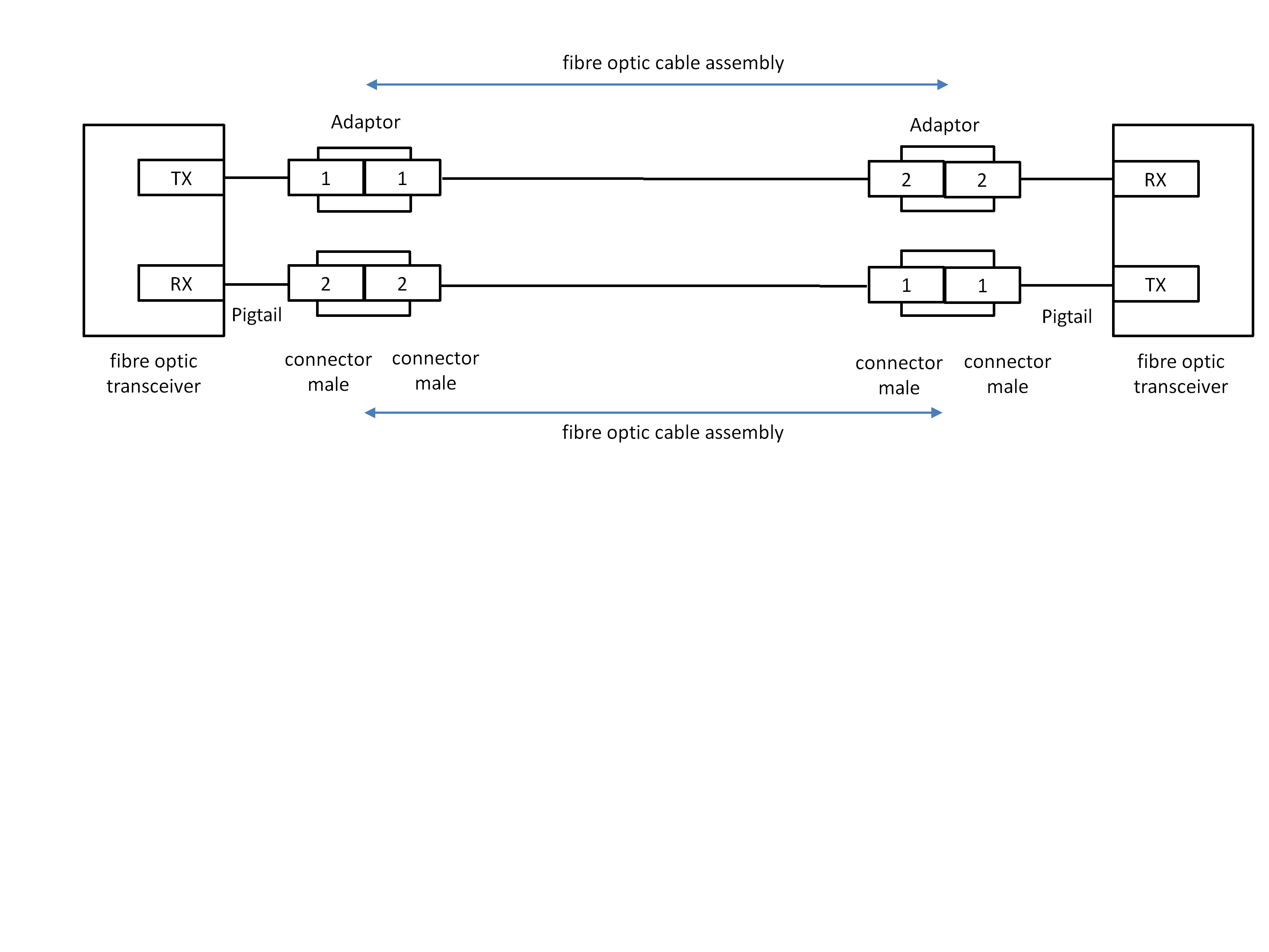 Figure 522: SpaceFibre lane comprising two Type-A fibre optic flight cable assemblies, one for each direction
Type-B fibre optic medium
General
A specific Type-B flight fibre optic medium shall be referred to by a unique descriptive name based on the type of insert and connector used in the following format: SpFi-TypeB-Insert-Connector, where Insert is the type of insert and Connector is a unique name for the type of connector and its specific contact allocation.
- 1 For example, a Type-B flight fibre optic medium using MT inserts in a 38999 connector with a specific contact allocation (D) is given the name SpFi-TypeB-MT-38999D.
- 2 The Type-B fibre optic medium is intended to be a generic specification of a cable assembly without defining the insert or connector body to be used.
Type-B fibre optic connector
The Type-B fibre optic connector shall use a rugged fibre optic connector.
Expanded beam should be used.
This technique gives better performance.
When a Type-B fibre optic connector uses one or more MT ferrule contacts they shall be as specified in mechanical specification IEC 61754-5:2005 and optical interface specification IEC 61755-3-31:2015 or IEC 61755-3-32:2015 which cover two different materials.
The IEC 61754-5:2005, IEC 61755-3-31:2015 and 61755-3-32:2015 definitions give the worst case performance.
Type-B fibre optic cables
The Type-B fibre optic cable shall contain two or more multi-mode, graded index, 50/125 µm fibres as specified in MIL-PRF-49291/1-01:2014.
The minimum quality level shall be IEC 60793-2-10 A1a.2:2015.
This corresponds to OM3, which achieve 10 Gbit/s over a link length of 300 m (IEEE802.3:2012 Clause 52.5) in a commercial grade fibre optic cable assembly.
The Type-B fibre shall have an attenuation of less than 5 dB per km.
The buffer and jacket of the Type-B fibre optic cable shall use materials suitable for space applications as specified in the following ECSS standards:
- ECSS-Q-ST-70-02 Thermal vacuum outgassing test for the screening of space materials.
- ECSS-Q-ST-70-21 Flammability testing for the screening of space materials.
- ECSS-Q-ST-70-29 The determination of off-gassing products from materials and assembled articles to be used in a manned space vehicle crew compartment.
Type-B fibre optic cable assemblies
Male connectors conforming to clause 5.4.6.2.2 shall be used on Type-B flight fibre optic cable assemblies.
The Type-B flight cable assembly shall use the fibre optic cable specified in clause 5.4.6.2.3.
The Type-B fibre optic cable assembly shall contain one or more pairs of fibre with each pair connected as specified in Table 531.
A Type-B fibre optic cable assembly containing two fibres is illustrated in Figure 523.
Table 531: Type-B flight fibre optic cable assembly connector contact terminations for each SpaceFibre lane
|
Signal at A end
|
Connection
|
Signal at B end
|
|
A-TX1
|
- Connection -
|
B-RX1
|
|
A-TX2
|
- Connection -
|
B-RX2
|
|
…
|
…
|
…
|
|
A-TXy
|
- Connection -
|
B-RXy
|
|
…
|
…
|
…
|
|
A-RXy
|
- Connection -
|
B-TXy
|
|
…
|
…
|
…
|
|
A-RX2
|
- Connection -
|
B-TX2
|
|
A-RX1
|
- Connection -
|
B-TX1
|
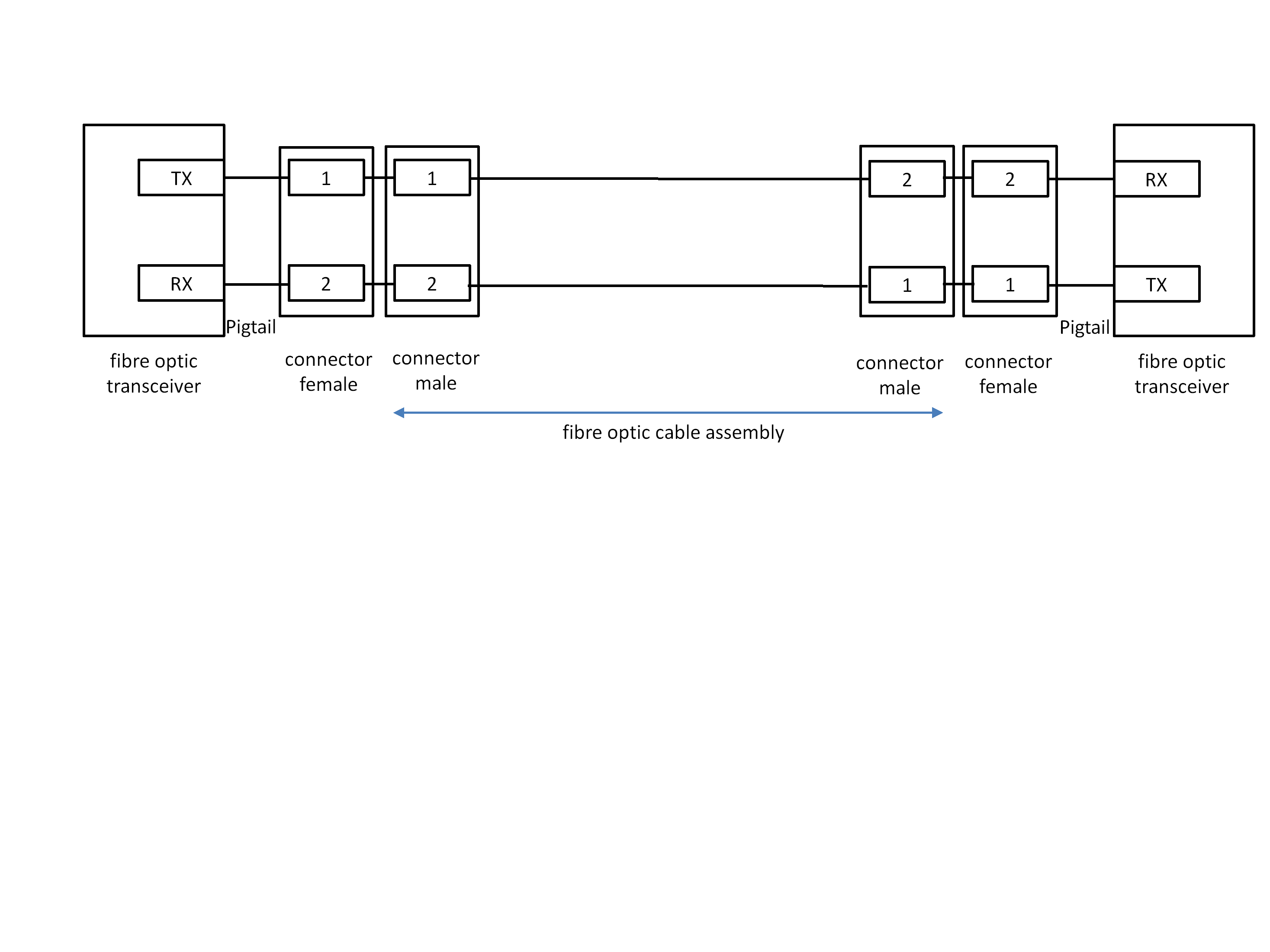 Figure 523: Type-B fibre optic flight cable assembly with one lane
A Type-B fibre optic cable assembly comprising several pairs should put the transmit signals at one side of the fibre optic cable assembly and the receive signals on the other side.
This is illustrated in the Type-B fibre optic cable assembly of Figure 524.
A Type-B fibre optic cable assembly comprising several pairs where only some pairs are being used should place the unused fibres between the transmit fibres and the receive fibres.
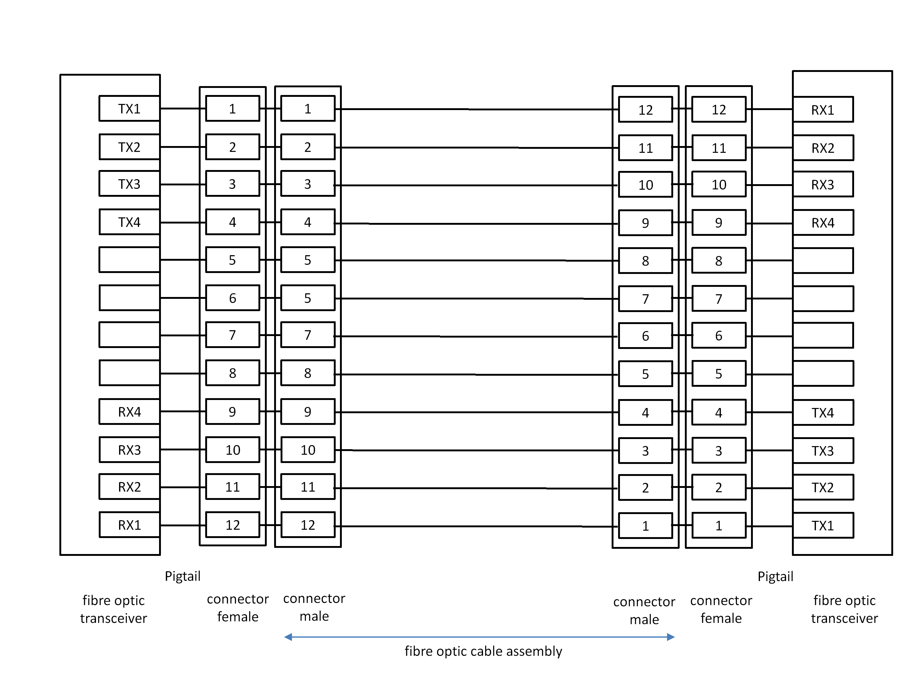 Figure 524: Type-B fibre optic flight cable assembly with several lanes
A Type-B fibre optic cable assembly being used for an asymmetric, multi-lane SpaceFibre interface shall be asymmetric with more fibres operating in one direction than in the other direction.
This is illustrated in the Type-B fibre optic cable assembly of Figure 525.
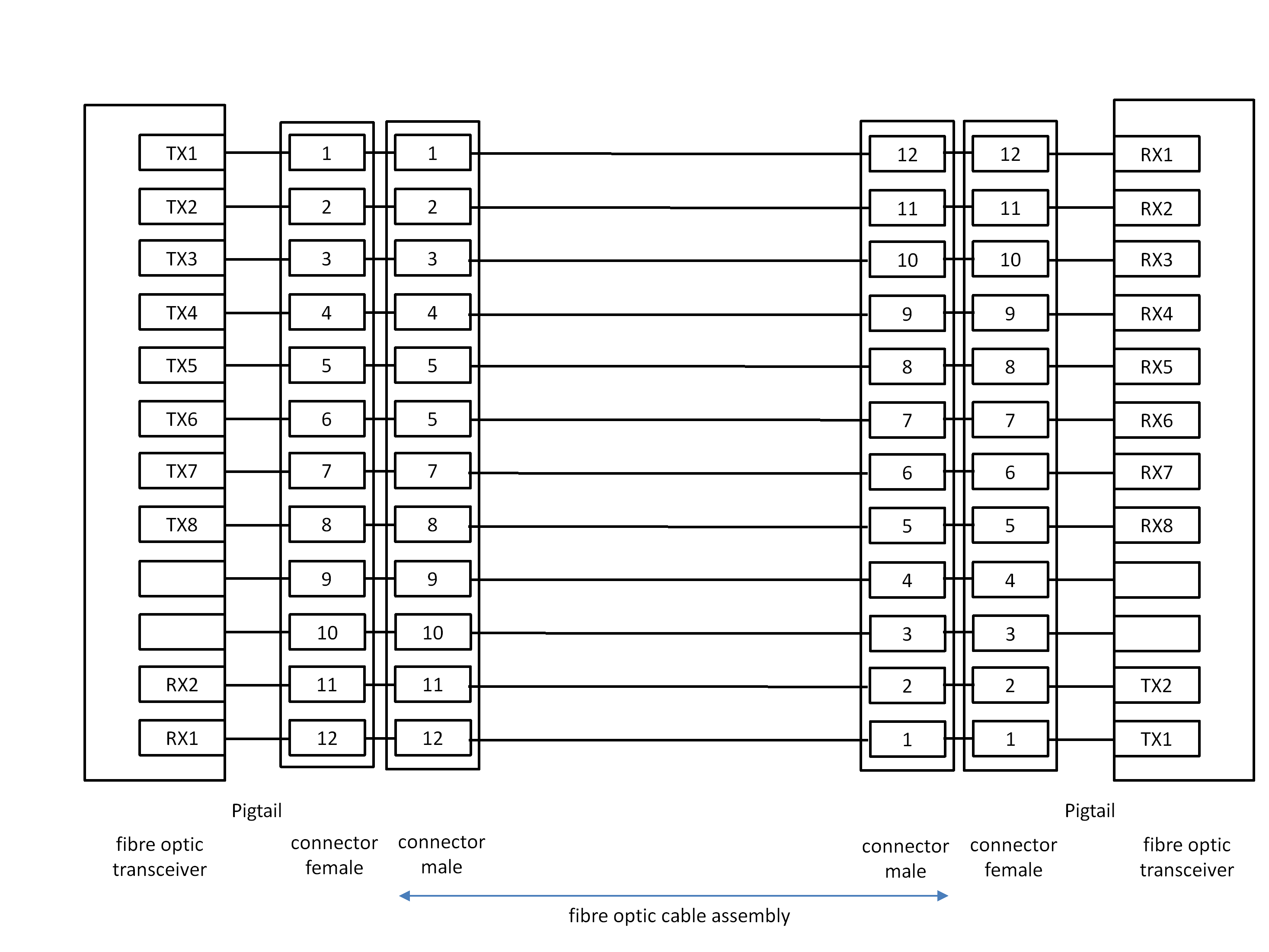 Figure 525: Type-B fibre optic flight cable assembly for an asymmetric link
The Type-B fibre optic cable assembly shall meet the specifications specified in Optical fibre cable assemblies ESCC Generic Specification: ESCC 3420:2017.
The Type-B fibre optic cable assembly shall follow the test procedures specified in Evaluation Test programme for optical fibre cable assemblies ESCC Basic Specification: ESCC 2263420:2017.
The Type-B fibre optic cable assembly should have a minimum bend radius of less than 25 mm.
Type-C Active Optical Cable
General
The Type-C active optical cable shall include the fibre optic transceiver in the male connector on the cable assembly.
This means that the connectors are electrical connectors and all the fibre optic components are integrated in the cable assembly. This makes assembly, integration and test much simpler.
Type-C fibre optic connector
The Type-C fibre optic connector shall provide the electrical signals listed in Table 532.
The Type-C fibre optic connector is not defined. It provides an electrical interface. The Type-C cable assembly is an active optical cable assembly with fibre optic transceivers incorporated in the connector housing of the cable assembly.
Table 532: Type-C flight active optical cable connector terminations for each SpaceFibre lane
|
Signal Name
|
Signal Type
|
Signal Function
|
|
TXp
|
CML +
|
Serial Data Transmit +
|
|
TXn
|
CML -
|
Serial Data Transmit -
|
|
RXp
|
CML +
|
Serial Data Receive +
|
|
RXn
|
CML -
|
Serial Data Receive -
|
|
NOSIG
|
LVTTL/LVCMOS
|
NoSignal Indication
|
|
TX FAIL
|
LVTTL/LVCMOS
|
Transmitter Fault Indication
|
|
TX_EN
|
LVTTL/LVCMOS
|
Transmitter Enable
|
|
RX_EN
|
LVTTL/LVCMOS
|
Receiver Enable
|
|
PWR
|
3,3 Volt Power
|
3,3 Volt ±10 %, 1 Watt Power Supply
|
|
GND
|
Ground
|
Ground
|
When more than one lane is provided in an active optical cable assembly, it shall provide one set of the signals listed in Table 532 for each lane.
When more than one lane is provided in an active optical cable assembly, the NOSIG and TX FAIL indications may be accessed by a shared interface.
For example, using I2C or a similar serial interface.
When more than one lane is provided in an active optical cable assembly, the power connection may be shared provided that it can provide sufficient power for all of the transceivers.
The Type-C connector on the equipment shall be a female connector.
Type-C active optical cable assemblies
Male connectors conforming to clause 5.4.6.3.2 shall be used on Type-C flight active optical cable assemblies.
The Type-C fibre optic cable assembly shall contain one or more pairs of fibre with each pair connected as specified in Table 533.
A Type-C fibre optic cable assembly containing two fibres is illustrated in Figure 526.
When more than one lane is provided in an active optical cable assembly, it shall provide one set of the connections listed in Table 533 for each lane.
Table 533: Type-C flight active optical cable assembly connector contact terminations for each SpaceFibre lane
|
Signal as A end
|
Connection
|
Signal at B end
|
|
TXp
|
- Connection -
|
RXp
|
|
TXn
|
- Connection -
|
RXn
|
|
RXp
|
- Connection -
|
TXp
|
|
RXn
|
- Connection -
|
TXn
|
|
NOSIG end A
|
No Connection
|
NOSIG end B
|
|
TX FAIL end A
|
No Connection
|
TX FAIL end B
|
|
PWR end A
|
No Connection
|
PWR end B
|
|
GND end A
|
No Connection
|
GND end B
|
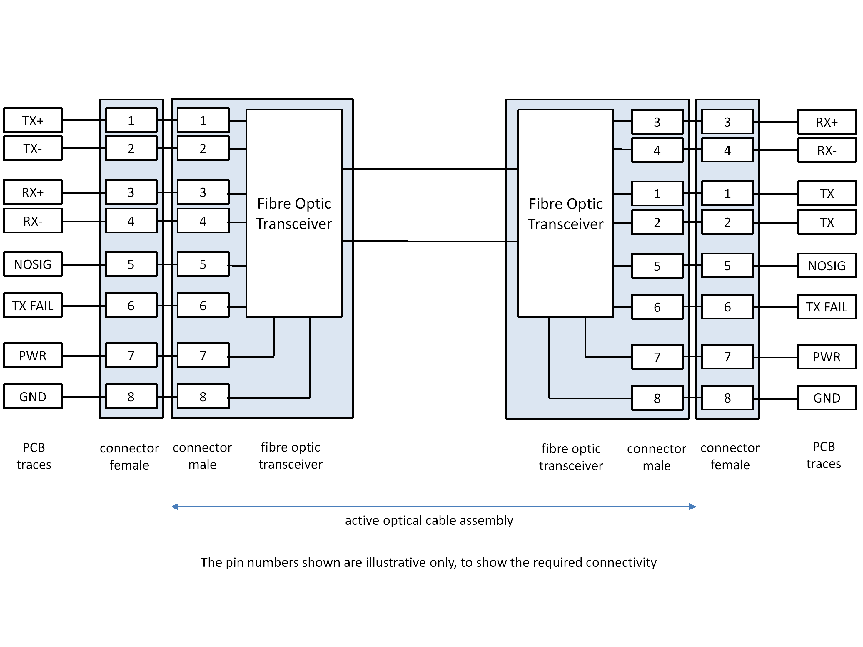 Figure 526: Type-C flight active optical cable assembly
The Type-C active optical cable assembly shall have a minimum bend radius of less than 25 mm.
The Type-C active optical cable assembly shall use materials suitable for space applications as specified in the following ECSS standards:
- ECSS-Q-ST-70-02 Thermal vacuum outgassing test for the screening of space materials.
- ECSS-Q-ST-70-21 Flammability testing for the screening of space materials.
- ECSS-Q-ST-70-29 The determination of off-gassing products from materials and assembled articles to be used in a manned space vehicle crew compartment.
The specific form of the Type-C fibre optic cable is not defined. Any fibre optic cable is acceptable provided that it meets the requirements for the Type-C active optical cable assemblies.
Lane layer
Lane layer responsibilities
The Lane layer shall establish communications across a SpaceFibre lane, encode data and control words into symbols, send and receive symbols over the lane, decode the received symbols into data and control words, and re-establish communications across the lane after errors that occur on the lane.
From the perspective of the implementation and the layers of the OSI Model, the Lane layer is a sub-layer of the Data Link layer.”
For a single lane link, the Lane layer shall receive data words and Data Link layer control words from the Data Link layer.
For a single lane link, the Lane layer shall pass data words and Data Link layer control words to the Data Link layer.
For a multi-lane link, the Lane layer shall receive data words, Multi-Lane control words and Data Link layer control words from the Multi-Lane layer.
For a multi-lane link, the Lane layer shall pass data words, Multi-Lane layer control words and Data Link layer control words to the Multi-Lane layer.
The Lane layer shall accept LaneReset commands from the Data Link or Multi-Lane layers.
The Lane layer shall accept near-end capability control information from the Data Link or Multi-Lane layer.
The Lane layer shall report far-end capability information received in the INIT3 Capability field to the Data Link or Multi-Lane layer.
The Lane layer shall accept RxOnly, TxOnly and FarEndActive lane control information from the Multi-Lane layer.
The Lane layer shall provide lane state information to the Multi-Lane layer or to the Data Link layer in the case of a single-lane link.
The Lane layer shall pass transmit symbols to the Physical layer.
The Lane layer shall receive 10-bit parallel data from the Physical layer.
The Lane layer shall control the Physical layer using the following signals:
- Line driver enable.
- Line receiver enable.
- Line clock data recovery enable.
- Invert RX polarity.
The Lane layer shall be informed by the Physical layer when there is no signal present at the receiver input, NoSignal.
The Lane layer shall be controlled by the following management parameters from the Management Information Base, where i is the lane number: - LaneStart(i).
- AutoStart(i).
- LaneReset(i).
- Parallel Loopback(i), when implemented.
- Standby reason(i). The Lane layer shall provide the following status information to the Management Information Base:
- Lane State(i).
- Error Information(i).
- Loss of Signal Information(i).
- Far End Capabilities (i).
- Receive Polarity(i).
The interfaces to and from the Lane layer are illustrated in Figure 527 for a single lane link and in Figure 528 for a multi-lane link.
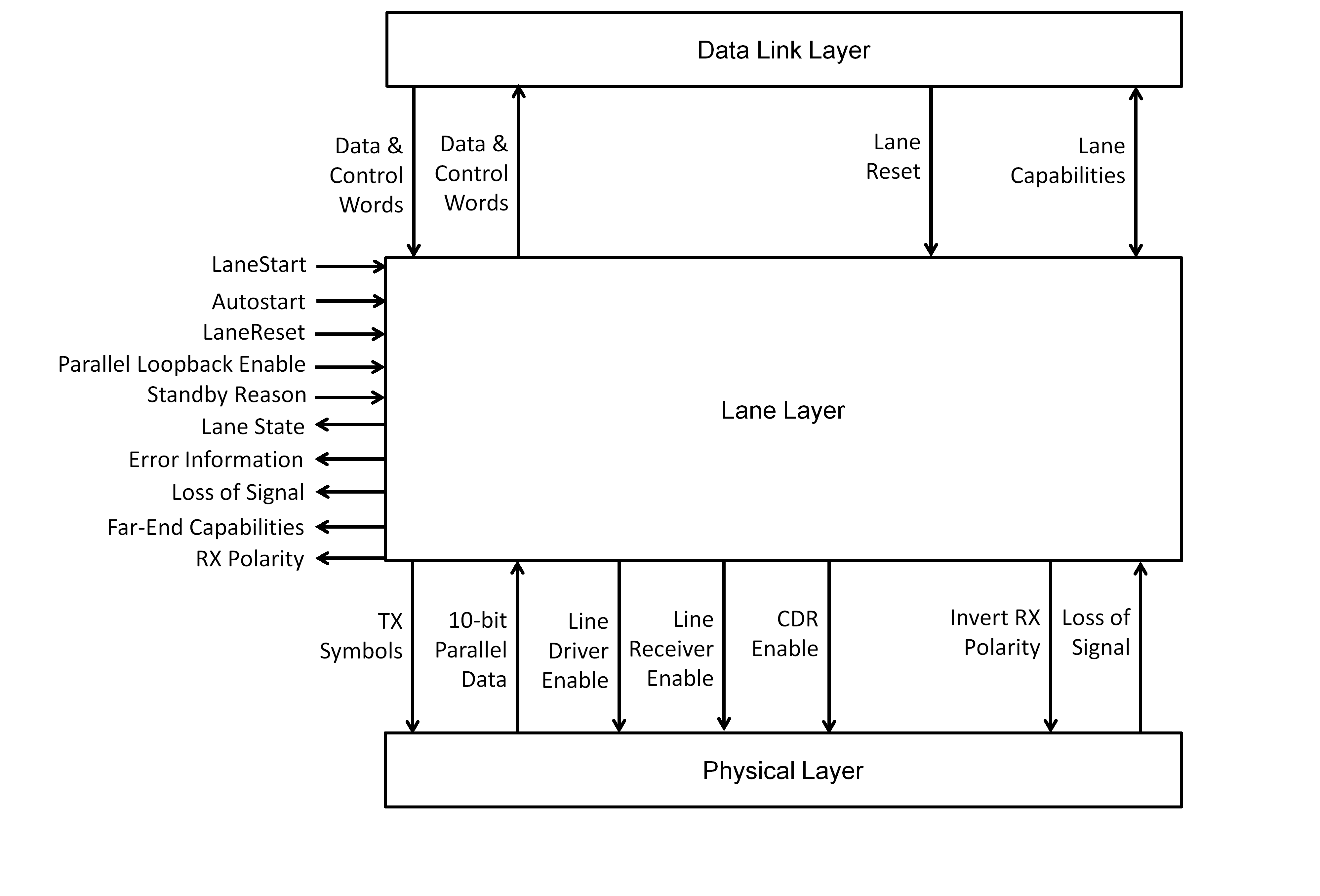 Figure 527: Interfaces to the Lane layer for a single lane link
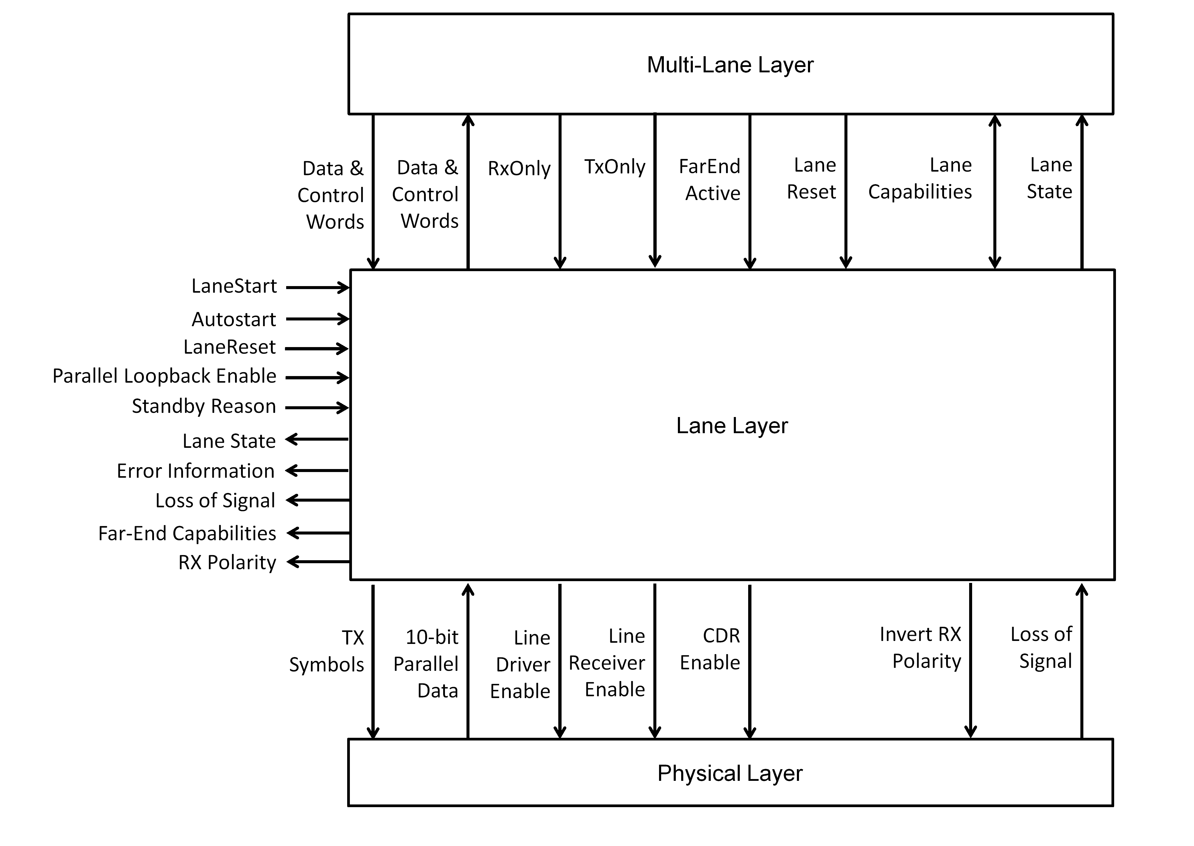 Figure 528: Interfaces to the Lane layer for a multi-lane link
Lane initialisation and standby management
General
The Lane Initialisation state machine shall control the initialisation of a SpaceFibre lane: establishing the connection and responding to standby management requests.
- 1 The state diagram for the lane initialisation state machine is illustrated in Figure 529.
- 2 As is normal for a state machine, the conditions that result in transitions in the lane initialisation state machine, e.g. Start, AutoStart, RxOnly, TxOnly and the values of the management parameters, are evaluated continuously.
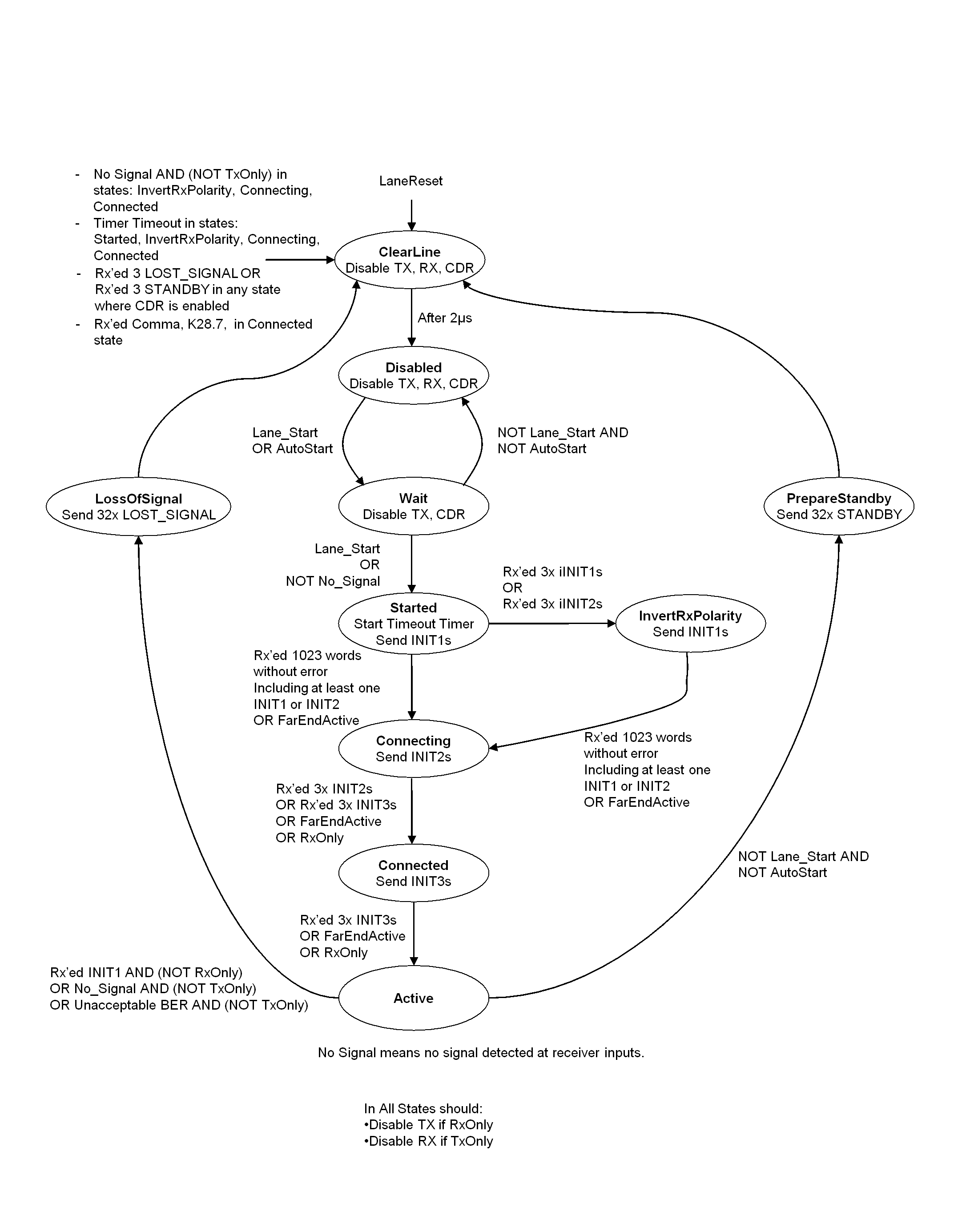 Figure 529: Lane initialisation state machine
RXERR word counter
An RXERR word counter shall be used to check the BER on the lane.
On LaneReset the value of the RXERR word counter shall be zero.
The way in which the RXERR words counter operates is detailed in clause 5.5.2.11.
FarEndActive
A FarEndActive indication shall be provided for each lane.
FarEndActive for a lane shall be asserted when the Lane Initialisation state machine at the far-end of that lane is in the Active state, as determined by a valid ACTIVE control word received by any lane at the near-end.
See clause 5.6.9.2.
For a single lane link FarEndActive shall be de-asserted.
ClearLine state
The Lane Initialisation state machine shall enter the ClearLine state on one of the following conditions:
- On LaneReset command.
- From the Started state, when the initialisation timeout timer expires.
- From the InvertRxPolarity state, when the initialisation timeout timer expires.
- From the Connecting state, when the initialisation timeout timer expires.
- From the Connected state, when the initialisation timeout timer expires.
- From the Connected state, when a comma, K28.7, is received.
- From any state where clock-data recovery (CDR) is enabled when 3 consecutive LOST_SIGNAL words are received.
- From any state where CDR is enabled when 3 consecutive STANDBY words are received.
- From the InvertRxPolarity state, when NoSignal is detected at the receiver and the TxOnly signal is not asserted.
- From the Connecting state, when NoSignal is detected at the receiver and the TxOnly signal is not asserted.
- From the Connected state, when NoSignal is detected at the receiver and the TxOnly signal is not asserted.
- From the PrepareStandby state, after sending 32 STANDBY control words.
- From the LossOfSignal state, after sending 32 LOST_SIGNAL control words.
The initialisation timeout timer is started in the Started state and stopped in the Active state. It times out if initialisation takes longer than the time to send 5000 words. The time to transmit 5000 words allows plenty of time for the receive clock-data recovery at the far-end of the lane to lock onto the transmitted signal, a response to be generated and returned to the near-end.
When in the ClearLine state the Lane Initialisation state machine shall initiate the following actions:
- Start a 2 µs timeout timer.
- Do NOT reset the Lane management parameter registers.
- Switch off receiver bit inversion.
- Disable the transmitter driver. When in the ClearLine state the Lane Initialisation state machine should disable the receiver and receive clock-data recovery circuitry.
This is to save power and also resets the clock recovery logic in case there has been a problem causing the SerDes to fail and the lane to disconnect in consequence.
The Lane Initialisation state machine shall leave the ClearLine state on the following condition:
- When the 2 µs timeout timer expires, move to the Disabled state.
This is more than long enough for signals to propagate through the longest permitted fibre optic cable, 100m, and back again, and to allow time for the signals to be processed at each end of the cable.
Disabled state
The Lane Initialisation state machine shall enter the Disabled state on the following condition:
- From the ClearLine state, after waiting there for 2 μs.
When in the Disabled state the Lane Initialisation state machine should disable the transmitter driver, receiver and related receive clock-data recovery (CDR).
The Lane Initialisation state machine shall leave the Disabled state on one of the following conditions, which are evaluated in the order given: - When LaneReset is asserted, move to the ClearLine state.
- When LaneStart or AutoStart is asserted, move to the Wait state.
Wait state
The Lane Initialisation state machine shall enter the Wait State on the following condition:
- From the Disabled state, when LaneStart or AutoStart is asserted. When in the Wait State the Lane Initialisation state machine shall initiate either one of the following actions:
- Enable the receiver including the NoSignal detection circuit.
- Enable only the NoSignal detection circuit. When in the Wait state the Lane Initialisation state machine should disable the transmitter driver.
This is to save power.
When in the Wait state, the Lane Initialisation state machine should disable the receiver clock-data recovery, CDR, circuit.
When in the Wait state and TxOnly is asserted, the Lane Initialisation state machine should disable the receiver.
The Lane Initialisation state machine shall leave the Wait State on one of the following conditions, which are evaluated in the order given:
- When LaneReset is asserted, move to the ClearLine state.
- When LaneStart and AutoStart are both de-asserted, move to the Disabled state.
- When LaneStart is asserted or No_Signal is de-asserted, move to the Started state.
Started state
The Lane Initialisation state machine shall enter the Started state on the following condition:
- From the Wait state, when LaneStart is asserted or No_Signal is de-asserted. When in the Started state the Lane Initialisation state machine shall initiate the following actions:
- On entry to the state, start an initialisation timeout timer, set to the time needed to transmit 5000 words.
- When RxOnly is not asserted, enable the transmitter driver.
- When TxOnly is not asserted, enable the receiver and CDR.
- Send INIT1 control words.
- Receive Lane layer control words, LLCW.
The time to transmit 5000 words allows plenty of time for the receive clock-data recovery at the far-end of the lane to lock onto the transmitted signal, a response to be generated and returned to the near-end.
When in the Started state and RxOnly is asserted the Lane Initialisation state machine should disable the transmitter driver.
This is to save power.
When in the Started state and TxOnly is asserted, the Lane Initialisation state machine should disable the receiver and the CDR.
When in the Started state the Lane Initialisation state machine may repeatedly send an INIT1 control word followed by up to 64 pseudo-random data words.
Replacing the stream of INIT1s by INIT1s followed by up to 64 pseudo-random data words reduces EM emissions during initialisation and supports adaptive equalisation which is likely to be necessary for data signalling rates above 5 Gbit/s.
The Lane Initialisation state machine shall leave the Started state on one of the following conditions, which are evaluated in the order given:
- When LaneReset is asserted, move to the ClearLine state.
- When the FarEndActive condition is asserted, move to the Connecting state.
- When a total of 1023 words, including at least one INIT1 or INIT2 control word, are received without any intervening RXERR control words, move to the Connecting state.
- When three inverse INIT1 or three inverse INIT2 control words are received without any intervening RXERR control words, move to the InvertRxPolarity state.
- When the initialisation timeout timer expires, move to the ClearLine state.
- When three consecutive LOST_SIGNAL or three consecutive STANDBY control words have been received, move to the ClearLine state.
The FarEndActive condition is received from a bi-directional lane of a multi-lane link, see clause 5.6.9.2. For a single lane link FarEndActive is de-asserted.
InvertRxPolarity state
The Lane Initialisation state machine shall enter the InvertRxPolarity state on one of the following conditions:
- From the Started state, when three inverse INIT1 control words are received without any intervening RXERR control words.
- From the Started state, when three inverse INIT2 control words are received without any intervening RXERR control words. When in the InvertRxPolarity state the Lane Initialisation state machine shall initiate the following actions:
- When RxOnly is not asserted, enable the transmitter driver.
- When TxOnly is not asserted, enable the receiver and CDR.
- Invert received bits.
- Send INIT1 control words.
- Receive Lane layer control words, LLCW.
When in the InvertRxPolarity state and RxOnly is asserted the Lane Initialisation state machine should disable the transmitter driver.
When in the InvertRxPolarity state and TxOnly is asserted, the Lane Initialisation state machine should disable the receiver and CDR.
This requirement has been added for symmetry with the other states, but the InvertRxPolarity state cannot be reached when TxOnly is asserted, as nothing can be received.
When in the InvertRxPolarity state the Lane Initialisation state machine may repeatedly send an INIT1 control word followed by up to 64 pseudo-random data words.
The Lane Initialisation state machine shall leave the InvertRxPolarity state on one of the following conditions, which are evaluated in the order given:
- When LaneReset is asserted, move to the ClearLine state.
- When NoSignal is detected at the receiver inputs and the TxOnly signal is not asserted, move to the ClearLine state.
- When the FarEndActive condition is asserted, move to the Connecting state.
- When a total of 1023 words, including at least one INIT1 or INIT2 control word, are received without any intervening RXERR control words, move to the Connecting state.
- When the initialisation timeout timer expires, move to the ClearLine state.
- When three consecutive LOST_SIGNAL or three consecutive STANDBY control words have been received, move to the ClearLine state.
Connecting state
The Lane Initialisation state machine shall enter the Connecting state on one of the following conditions:
- From the Started state, when FarEndActive is asserted.
- From the Started state, when a total of 1023 words, including at least one INIT1 or INIT2 control word, are received without any intervening RXERR control words.
- From the InvertRxPolarity state, when FarEndActive is asserted.
- From the InvertRxPolarity state, when a total of 1023 words, including at least one INIT1 or INIT2 control word, are received without any intervening RXERR control words. When in the Connecting state the Lane Initialisation state machine shall initiate the following actions:
- When RxOnly is not asserted, enable the transmitter driver.
- When TxOnly is not asserted, enable the receiver and CDR.
- Send INIT2 control words.
- Receive Lane layer control words, LLCW.
When in the Connecting state and RxOnly is asserted the Lane Initialisation state machine should disable the transmitter driver.
When in the Connecting state and TxOnly is asserted, the Lane Initialisation state machine should disable the receiver and CDR.
When in the Connecting state the Lane Initialisation state machine may repeatedly send an INIT2 control word followed by up to 64 pseudo-random data words.
The Lane Initialisation state machine shall leave the Connecting state on one of the following conditions, which are evaluated in the order given: - When LaneReset is asserted, move to the ClearLine state.
- When NoSignal is detected at the receiver inputs and the TxOnly signal is not asserted, move to the ClearLine state.
- When RxOnly is asserted, move to the Connected state.
- When the FarEndActive condition is asserted, move to the Connected state.
- When three INIT2 control words are received without any intervening RXERR control words, move to the Connected state.
- When three INIT3 control words are received with the same initialisation parameters and without any intervening RXERR control words, move to the Connected state.
- When the initialisation timeout timer expires, move to the ClearLine state.
- When three consecutive LOST_SIGNAL or three consecutive STANDBY control words have been received, move to the ClearLine state.
Connected state
The Lane Initialisation state machine shall enter the Connected state on one of the following conditions:
- From the Connecting state, when FarEndActive is asserted.
- From the Connecting state, when RxOnly is asserted.
- From the Connecting state, when three INIT2 control words are received without any intervening RXERR control words.
- From the Connecting state, when three INIT3 control words are received with the same initialisation parameters and without intervening RXERR control words. When in the Connected state the Lane Initialisation state machine shall initiate the following actions:
- When RxOnly is not asserted, enable the transmitter driver.
- When TxOnly is not asserted, enable the receiver and CDR.
- Send INIT3 control words with the initialisation parameters set in the most significant character, the Capability field, as follows:
- Bit 0: the INIT3LinkResetFlag.
- Bit 1: the INIT3LaneStart Flag.
- Bit 2: the INIT3DataScrambled Flag.
- Bit 3: the INIT3Multi-LaneCapable Flag.
- Bit 4: the INIT3RoutingSwitch Flag.
- Bits 5 to 7: reserved bits that are set to zero when transmitted and ignored when received.
- Receive Lane layer control words, LLCW.
- Store the initialisation parameters supplied by the INIT3 control word most significant character, the Capability field.
- When three INIT3 control words are received with the same initialisation parameters and without any intervening RXERR control words, pass the INIT3 Capability field value to the Data Link or Multi-Lane layer and to the Management Information Base.
- Clear the RXERR words counter to zero.
When in the Connected state and RxOnly is asserted the Lane Initialisation state machine should disable the transmitter driver.
When in the Connected state and TxOnly is asserted, the Lane Initialisation state machine should disable the receiver and CDR.
The Lane Initialisation state machine shall leave the Connected state on one of the following conditions, which are evaluated in the order given: - When LaneReset is asserted, move to the ClearLine state.
- When NoSignal is detected at the receiver inputs and the TxOnly signal is not asserted, move to the ClearLine state.
- When RxOnly is asserted, move to the Active state.
- When the FarEndActive condition is asserted and at least one INIT3 control word has been sent, move to the Active state.
- When three INIT3 control words are received with the same initialisation parameters and without any intervening RXERR control words and at least three INIT3 control words have been sent, move to the Active state.
- When the initialisation timeout timer expires, move to the ClearLine state.
- When three consecutive LOST_SIGNAL or three consecutive STANDBY control words have been received, move to the ClearLine state.
- When a Comma, K28.7, is received, move to the ClearLine state.
Requirement 5.5.2.10.e.8 reduces the error recovery time when INIT3 control words are lost for any reason. Since LOST_SIGNAL and STANDBY both start with a Comma, requirement 5.5.2.10.e.8 will preempt requirement 5.5.2.10.e.7. Requirement 5.5.2.10.e.7 is therefore strictly unnecessary but is retained for clarity, since LOST_SIGNAL and STANDBY are valid control words rather than an error condition.
Active state
The Lane Initialisation state machine shall enter the Active state on the following conditions:
- From the Connected state, when FarEndActive is asserted and at least one INIT3 control word has been sent.
- From the Connected state, when RxOnly is asserted.
- From the Connected state, when three INIT3 control words with the same Capability field value have been received without intervening RXERR control words and at least three INIT3 control words have been sent.
The Lane Initialisation state machine enters the Active state when initialisation is complete.
When in the Active state the Lane Initialisation state machine shall initiate the following actions:
- Stop the initialisation timeout timer.
- When RxOnly is not asserted, enable the transmitter driver.
- When TxOnly is not asserted, enable the receiver and CDR.
- Enable transmission of data and control words from the Multi-Lane or Data Link layer.
- Pass received data and control words up to the Multi-Lane or Data Link layer.
- Increase the RXERR words counter by one every time an RXERR is received.
- Decrease the RXERR words counter by one every time 15000 to 16384 more words have been received.
- When a LOST_SIGNAL, STANDBY or INIT1 control word is received, pass an RXERR word up to the Multi-Lane or Data Link layer.
- Filter out Lane control words, see Table 53, so that they are not passed up to the Multi-Lane or Data Link layer.
Lane control words are used by the Lane Initialisation state machine and nothing is passed up to the Multi-Lane layer or Data Link layer in their place.
When in the Active state and RxOnly is asserted the Lane Initialisation state machine should disable the transmitter driver.
When in the Active state and TxOnly is asserted, the Lane Initialisation state machine should disable the receiver and CDR
The Lane Initialisation state machine shall leave the Active state on one of the following conditions, which are evaluated in the order given:
- When LaneReset is asserted, move to the ClearLine state.
- When NoSignal is asserted indicating that there is a loss of signal at the receiver and TxOnly is not asserted, move to the LossOfSignal state.
- When the RXERR words counter reaches 255 and TxOnly is not asserted, move to the LossOfSignal state.
- When an INIT1 control word is received and RxOnly is not asserted, move to the LossOfSignal state.
- When the LaneStart and AutoStart signals are both de-asserted, move to the PrepareStandby state.
- When three consecutive LOST_SIGNAL or three consecutive STANDBY control words have been received, move to the ClearLine state.
- When leaving this state, pass at least one RXERR word up to the Multi-Lane or Data Link layer.
If the RXERR words error counter reaches 255, the bit error rate in the lane is very high and the lane is reinitialised to try to recover correct operation.
PrepareStandby state
The Lane Initialisation state machine shall enter the PrepareStandby state on the following condition:
- From the Active state, when LaneStart and AutoStart signals are both de-asserted. When in the PrepareStandby state the Lane Initialisation state machine shall initiate the following action:
- When RxOnly is not asserted, enable the transmitter driver.
- When TxOnly is not asserted, enable the receiver and CDR.
- Send 32 STANDBY control words.
- 1 32 STANDBY control words are sufficient to make sure that three STANDBY control words have passed through the receive pipeline and receive elastic buffer at the far-end of the lane, before the subsequent NoSignal at receiver, caused by the near-end of the lane entering the ClearLine state, is detected by the far-end receiver.
- 2 When the near-end of a SpaceFibre lane enters the PrepareStandby state, the far-end enters the ClearLine state due to reception of three STANDBY control words and not via the LossOfSignal state due to detecting NoSignal.
When in the PrepareStandby state and RxOnly is asserted the Lane Initialisation state machine should disable the transmitter driver.
When in the PrepareStandby state and TxOnly is asserted, the Lane Initialisation state machine should disable the receiver and CDR.
The Lane Initialisation state machine shall leave the PrepareStandby state on one of the following conditions, which are evaluated in the order given: - When LaneReset is asserted, move to the ClearLine state.
- When 32 STANDBY control words have been sent, move to the ClearLine state.
- When three consecutive LOST_SIGNAL or three consecutive STANDBY control words have been received, move to the ClearLine state.
LossOfSignal state
The Lane Initialisation state machine shall enter the LossOfSignal state on the following conditions:
- From the Active state when an INIT1 is received and RxOnly is NOT asserted.
- From the Active state when NoSignal at Receiver signal is asserted, indicating that there is no signal present on the receiver inputs, and TxOnly is NOT asserted.
- From the Active state when the RXERR words counter overflows and TxOnly is NOT asserted.
A counter increases its value every time an RXERR word is received, and periodically decreases its value. This type of counter is known as a leaky-bucket counter. The overflow of this counter causes the exit condition from Active state and an indication of a persistent error.
When in the LossOfSignal state the Lane Initialisation state machine shall initiate the following action:
- When RxOnly is not asserted, enable the transmitter driver.
- When TxOnly is not asserted, enable the receiver and CDR.
- Send 32 LOST_SIGNAL control words.
When the near-end of the SpaceFibre lane enters the LossOfSignal state and sends LOST_SIGNAL control words, the far-end of the link enters the Clearline state due to reception of three LOST_SIGNAL control words and not due to detecting No_Signal.
When in the LossOfSignal state and RxOnly is asserted the Lane Initialisation state machine should disable the transmitter driver.
When in the LossOfSignal state and TxOnly is asserted, the Lane Initialisation state machine should disable the receiver and CDR.
This requirement has been added for symmetry with the other states, but technically if it is in LossOfSignal the lane cannot be TxOnly, as it was receiving symbols.
The Lane Initialisation state machine shall leave the LossOfSignal state on one of the following conditions, which are evaluated in the order given:
- When LaneReset is asserted, move to the ClearLine state.
- When 32 LOST_SIGNAL control words have been sent, move to the ClearLine state.
- When three consecutive LOST_SIGNAL or three consecutive STANDBY control words have been received, move to the ClearLine state.
Data signalling rate compensation
The transmitters at each end of a lane shall send data at the same nominal data signalling rate.
The maximum permitted difference in the data signalling rates, when each end of the lane is operating at nominally the same data signalling rate, shall be ± 0,01 %.
The data signalling rate of a transmitter at one end of a lane and a receiver at the other end of a lane can be different due to differences in the local clocks being used at each end of the lane. Since crystal oscillators are normally specified in parts per million, ppm, note that ± 0,01 % is equal to ±100 parts per million. Typical crystal oscillators are better than ±100 parts per million.
A receive elastic buffer shall be used to compensate for differences in the data signalling rate at each end of the lane.
SKIP control words shall be inserted every 5000 words in the transmit data stream, once the lane state machine has reached the Active state.
The SKIP control word shall be used to compensate for any slight difference in the data signalling rate between the two ends of the lane.
IDLE words
When there is no other data or control word to send, an IDLE word shall be sent.
It is essential not to have gaps in the data being sent because the CDR in the receiver has to maintain lock on the incoming data stream.
When received, IDLE control words shall be discarded when they are read out of the receive elastic buffer.
Parallel loopback
When a serial loopback is not provided, see clause 5.4.2.2, a parallel loopback facility shall be provided in the SpaceFibre port for test purposes.
When a serial loopback is provided, a parallel loopback facility may also be provided in the SpaceFibre port for test purposes.
When enabled, the near-end parallel loopback shall replace the words in the receive stream, after data rate adjustment, with the words from the transmit stream.
When enabled, the far-end parallel loopback shall replace the words in the transmit stream, with the words from the receive stream after data rate adjustment.
Symbol synchronisation
The boundary between symbols shall be determined by detecting the comma sequences.
The Positive Comma sequence shall be 0011111.
The Negative Comma sequence shall be 1100000.
At least all 7-bits of the bit comma sequence are used for symbol synchronisation.
Both positive and negative commas shall be detected and used for synchronisation.
Synchronisation may be performed on only positive commas or only negative commas when using legacy SerDes devices.
The 10-bit wide input stream shall be aligned or realigned to form a stream of correctly aligned symbols so that each 10-bit group contains one complete symbol.
The 10-bit wide input stream shall be realigned every time a comma sequence is detected in a different position to the position of the last comma detected.
Word synchronisation
A symbol word shall comprise four symbols.
The first symbol to be transmitted in a symbol word shall be the least significant symbol.
A comma shall only occur in the least significant symbol position of a symbol word.
Word synchronisation shall be performed whenever a comma sequence is received.
Word synchronisation shall be achieved by selecting symbols in consecutive groups of four so that the comma sequence appears in the least significant symbol position.
On word synchronisation, the first word shall comprise a comma control symbol in the least significant symbol position, together with the following three symbols.
Each subsequent group of four symbols shall form each of the following symbol words.
Word realignment shall occur when any of the following conditions occur:
- The 10-bit wide data stream is realigned, see requirement 5.5.6g.
- A comma occurs in any position other than the least significant symbol position of a word.
When word realignment occurs, the current word being received shall be set to the RXERR control word.
If a disparity error occurs, it shall be indicated to the receive synchronisation state machine and the current symbol set to Rx Error, K0.0.
If an unrecognised symbol is received then a symbol error shall be indicated to the receive synchronisation state machine and the current symbol set to Rx Error, K0.0.
If a word contains an Rx Error, K0.0, symbol indicating an error, that word together with the previous word shall be set to the RXERR control word.
An 8B/10B disparity error is detected in the next symbol that has disparity of ±2. All control words have at least one symbol with ±2 disparity with the exception of the EDF control word where the disparity depends on the specific values of the symbols following the EDF symbol in the EDF control word. It is therefore possible for the EDF control word to have zero disparity. The SpaceFibre protocol ensures that an EDF is always followed by a control word with at least one symbol with ±2 disparity. When an error is detected using disparity, both the word in which the error occurred and the previous word are changed to RXERR. This ensures that data frames containing an error are not passed to the upper layers without an error being flagged.
Receive synchronisation state machine
General
A receive synchronisation state machine shall be used to determine when incoming symbols and words are synchronised.
The state diagram for the receive synchronisation state machine is illustrated in Figure 530.
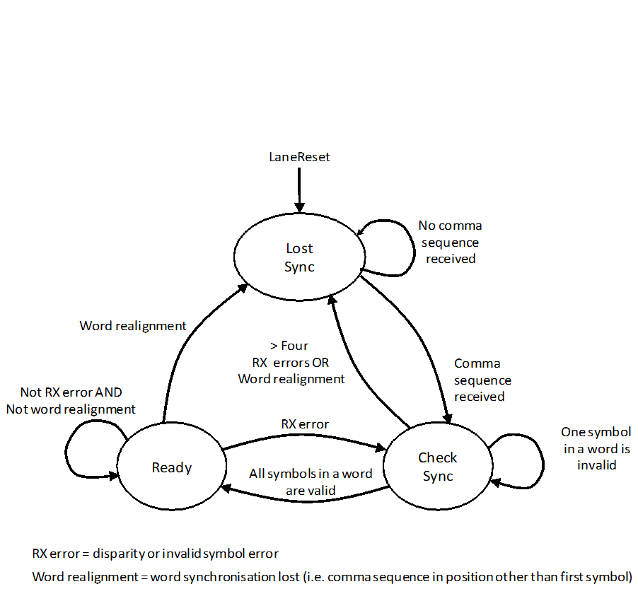 Figure 530: Receive synchronisation state machine
LostSync State
The LostSync state shall be entered on one of the following conditions:
- LaneReset command.
- From the CheckSync state, when word realignment occurs or when a total of more than four symbols are received that are invalid or contain a disparity error.
- From the Ready state, when word realignment occurs. When in the LostSync state the Receive Synchronisation state machine shall initiate the following action:
- Replace any received data and control words with RXERR control words. The Receive Synchronisation state machine shall leave the LostSync State on the following condition:
- When a comma sequence is received, move to the CheckSync state.
CheckSync State
The CheckSync state shall be entered on one of the following conditions:
- From the LostSync state, when a comma sequence is received.
- From the Ready state, when a disparity error occurs or an invalid symbol is detected. When in the CheckSync state the Receive Synchronisation state machine shall initiate the following actions:
- Receive symbols.
- Count the number of words received that contain an invalid symbol or contain a disparity error. The Receive Synchronisation state machine shall leave the CheckSync State on one of the following conditions, which are evaluated in the order given:
- When LaneReset is asserted, move to the LostSync state.
- When word realignment occurs, move to the LostSync state.
- When a total of more than four words are received that contain an invalid symbol or contain a disparity error, move to the LostSync state.
- When all symbols within a word are valid, move to the Ready state.
Ready State
The Ready state shall be entered on the following condition:
- From the CheckSync state, when all symbols within a word are valid. When in the Ready state the Receiver Synchronisation state machine shall initiate the following action:
- Receive symbols. The Receiver Synchronisation state machine shall leave the Ready state on one of the following conditions, which are evaluated in the order given:
- When LaneReset is asserted, move to the LostSync state.
- When a disparity error occurs or an invalid symbol is received, move to the CheckSync state.
- When word realignment occurs, move to the LostSync state.
Multi-Lane layer
Multi-Lane layer responsibilities
The Multi-Lane layer shall coordinate the operation of multiple lanes as a single SpaceFibre link, and, when possible, recover from lane failures.
From the perspective of the implementation and the layers of the OSI Model, the Multi-Lane layer is a sub-layer of the Data Link layer.
The Multi-Lane layer shall send and receive data words and Data Link layer control words over several lanes operating together as a single link.
The Multi-Lane layer allows several lanes to operate together to provide higher bandwidth than a single lane can provide.
The Multi-Lane layer shall receive data words and Data Link layer control words from the Data Link layer.
The Multi-Lane layer shall pass data words and Data Link layer control words received from the Lane layer to the Data Link layer.
The Multi-Lane layer shall pass data words and Data Link and Multi-Lane layer control words to the Lane layer.
The Multi-Lane layer shall receive data words and Data Link and Multi-Lane layer control words from the Lane layer.
The Multi-Lane layer shall inform the Lane layer when the lane is a transmit only lane, TxOnly.
The Multi-Lane layer shall inform the Lane layer when the lane is a receive only lane, RxOnly.
The Multi-Lane layer shall inform the Lane layer when the far-end of the lane is in the Active state, FarEndActive.
In a single lane link FarEndActive is de-asserted.
The Multi-Lane layer shall be able to assert LaneReset individually to one or more near-end lane interfaces.
The Multi-Lane layer is then able to perform a LaneReset on each lane in the Lane layer independently.
The Multi-Lane layer shall be informed by the Lane layer of the state of each lane.
See clause 5.6.9.
The Multi-Lane layer shall accept near-end capability control information from the Data Link.
The Multi-Lane layer shall report far-end capability information for all lanes, which is received in the INIT3 Capability field, to the Data Link layer.
The Multi-Lane layer shall pass near-end capability control information to the Lane layer.
The Multi-Lane layer shall receive far-end capability information, which is received in the INIT3 Capability field for each lane, from the Lane layer.
The Multi-Lane layer shall have a management parameter which determines which lanes are allowed to send, TxEn, and receive, RxEn.
The Multi-Lane layer shall provide the following status information to the Management Information Base:
- Data-sending lanes.
- Data-receiving lanes.
- Alignment state.
The interfaces to and from the Multi-Lane layer are illustrated in Figure 531.
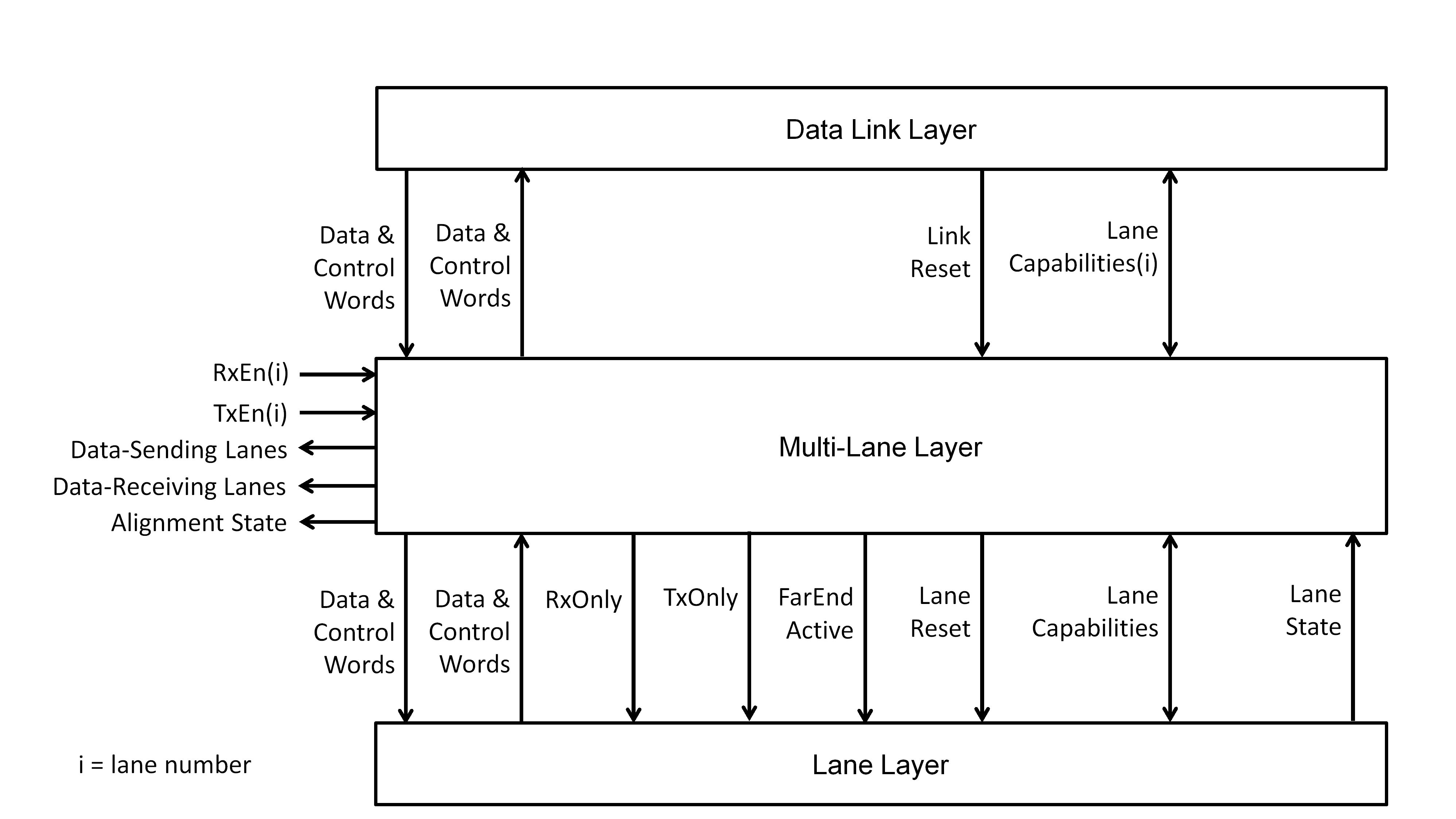 Figure 531: Interfaces to Multi-Lane layer
Multi-Lane link
A multi-lane SpaceFibre link shall contain two or more lanes that operate together to provide greater bandwidth than a single lane can provide.
Each lane in a Multi-Lane layer shall have a lane number, starting at 0 and incrementing for each lane.
So if there are four lanes they are numbered 0, 1, 2 and 3.
The maximum number of lanes shall be 16.
Lane number L at one end of the link shall be connected to lane number L at the other end of the link.
A multi-lane interface with a given number of lanes shall be able to be connected to a multi-lane interface with a different number of lanes, provided that lanes of the same number are connected together.
A multi-lane link with different number of lanes at each end of the link is illustrated in Figure 532.
All lanes in a multi-lane link shall operate at the same data signalling rate from the same clock or reference clock.
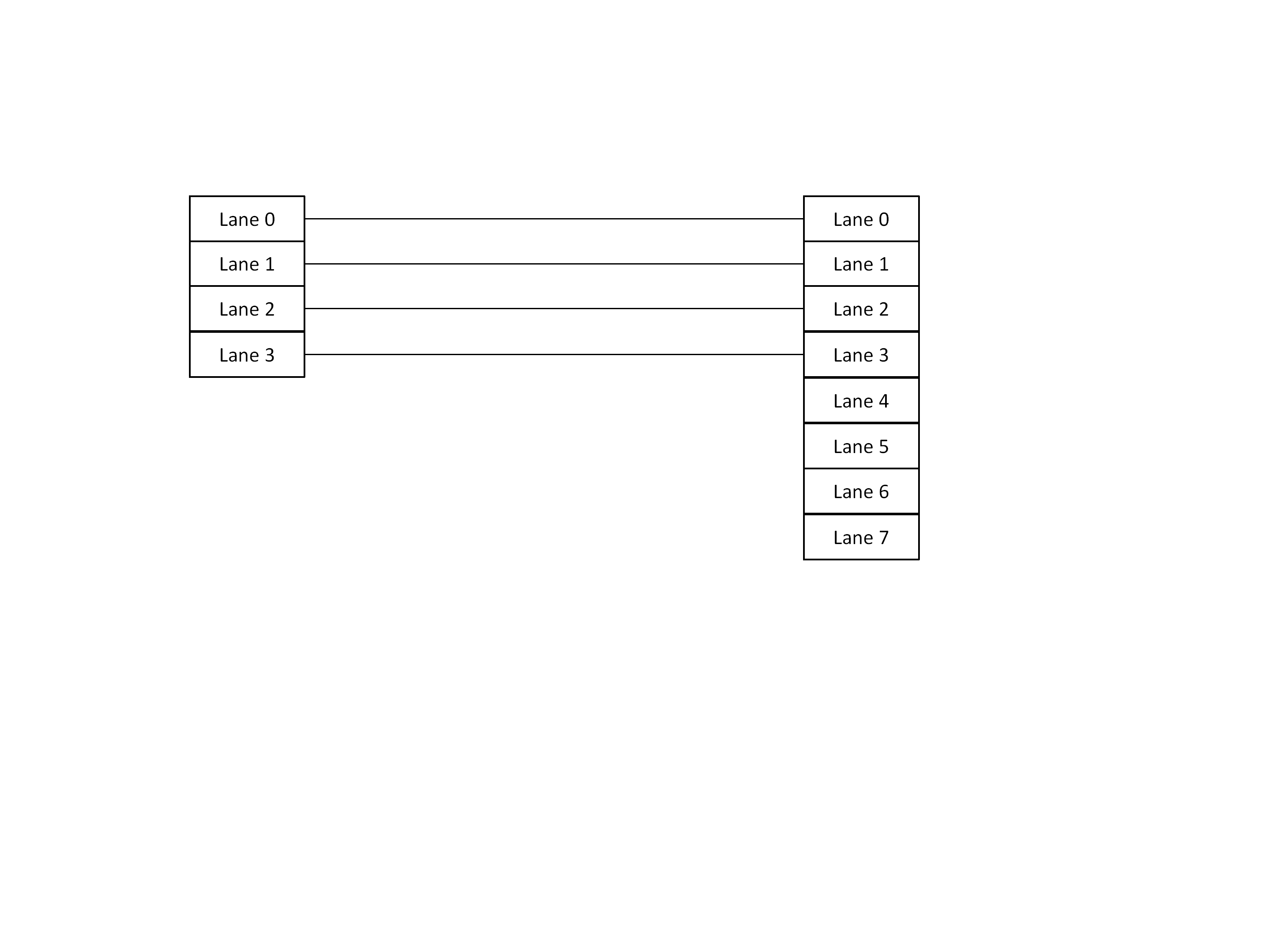 Figure 532: Multi-Lane link with different number of lanes at each end
Multi-Lane bypass
Multi-Lane operation shall be able to be switched off or bypassed, so that the SpaceFibre link operates over one lane only.
Multi-Lane distribution
Multi-Lane rows
Data and control words to be sent over a multi-lane link shall be distributed across the data-sending lanes of the link.
The set of data and control words passed, one to each data-sending lane, shall together form a row of words across the data-sending lanes.
Multi-Lane distribution is illustrated in Figure 533. There are three active data-sending lanes in this example and one which is not active. The word numbering is for data words from data frames. Control words from the Lane layer are replicated across all lanes.
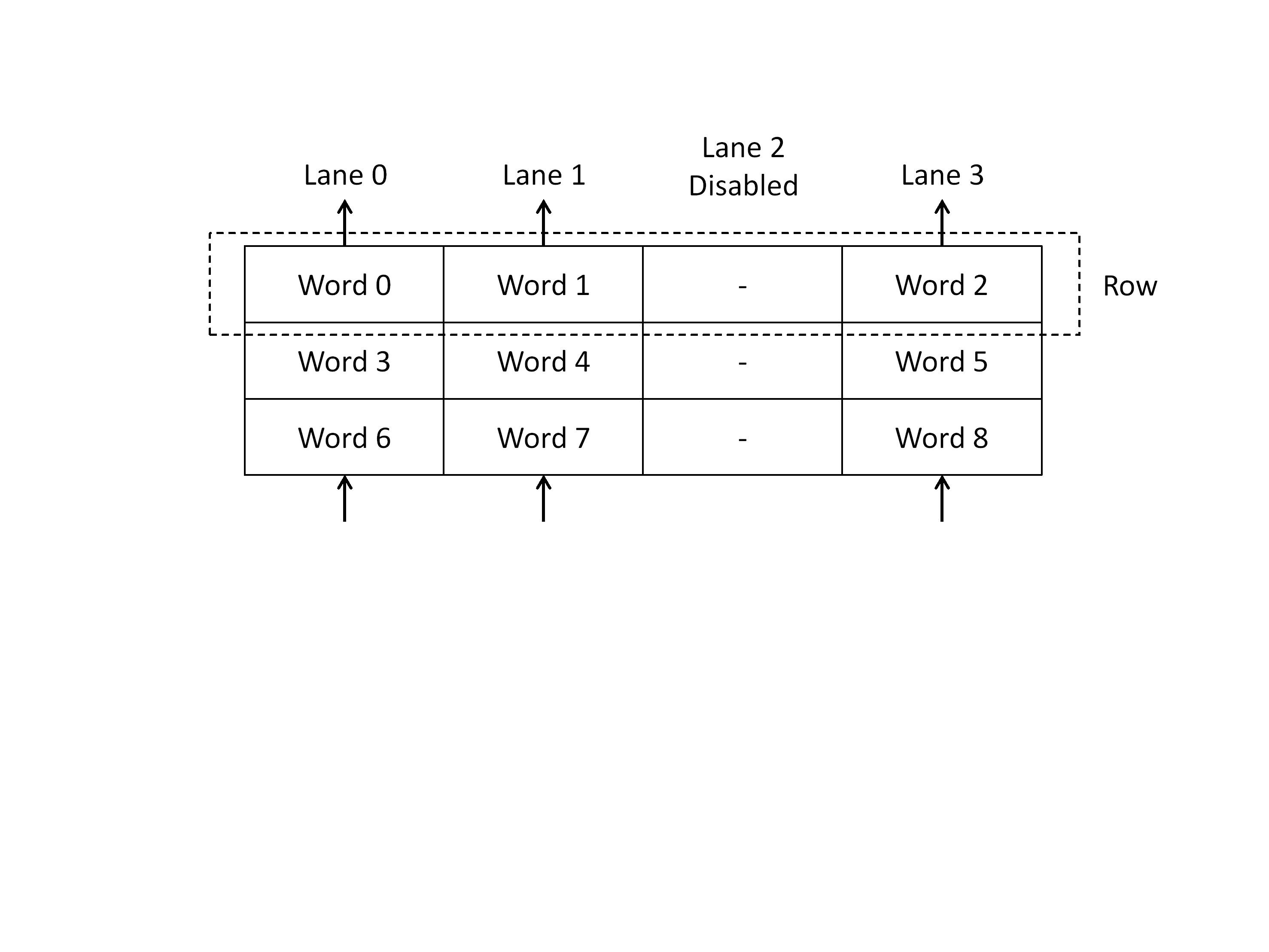 Figure 533: Words forming a row across a multi-lane link
A row shall comprise a set of L words where L is the number of data-sending lanes.
When sending data link control words, each data link control word shall be replicated and sent over all data-sending lanes forming a row filled with the same control word, with the exception of the EDF control words which have different CRC values.
- 1 The data link control words can then be generated and processed at a rate that is independent of the number of lanes being used. This lower, fixed rate simplifies the implementation.
- 2 The CRC16 field of an EDF is different for each lane according to the data sent in that lane.
When receiving the replicated Data Link control words sent over all data-sending lanes forming a row, any one of them shall be selected and passed to the Data Link layer.
Laning of data frames
A sequence of data words including EOPs, EEPs and Fills from a data frame shall be spread across the sending row, so that the first data word goes over the lowest number data-sending lane, the next over the following lowest number data-sending lane, up to the highest number data-sending lane.
This is illustrated in Figure 534. The lowest number data-sending lane transfers the first data word of the row, the next data-sending lane the next data word of the row, and so on to the highest number data-sending lane which transfers the last data word of the row.
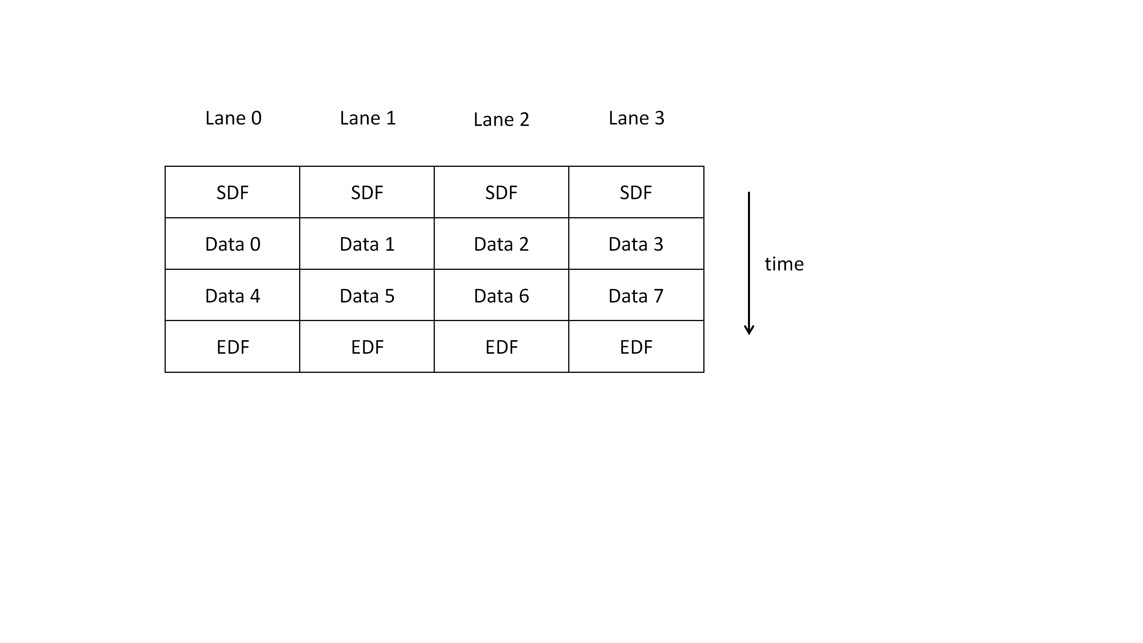 Figure 534: Spreading data across a multi-lane link
If the size of a data frame is not a multiple of the number of data-sending lanes, PAD control words shall be used for padding any unused words in the sending row at the end of the data frame, prior to the EDF, with the number of PAD control words being less than the number of data-sending lanes.
An example is shown in Figure 535.
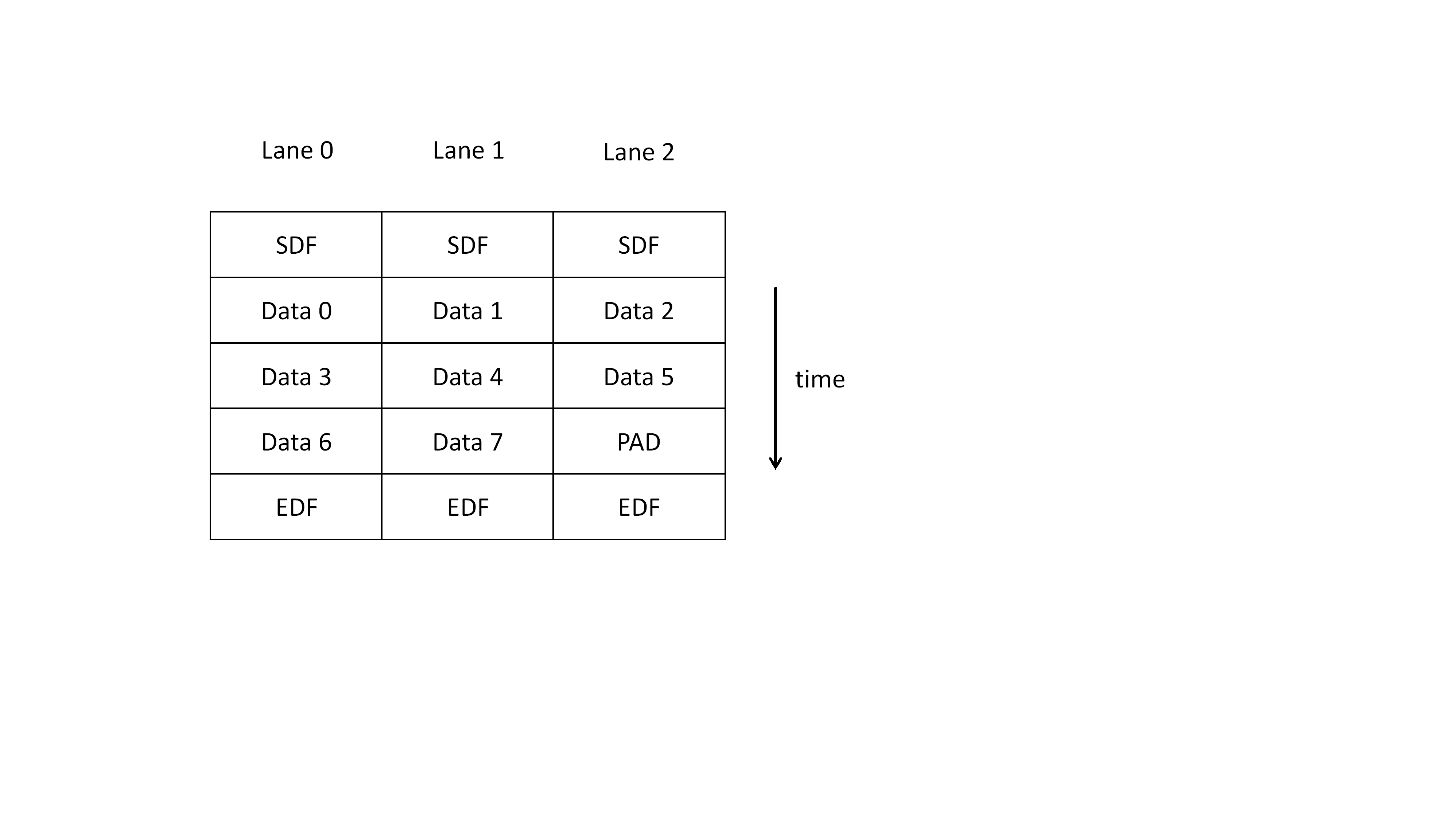 Figure 535: PAD control words in a multi-lane link
Data scrambling shall be applied over each data-sending lane independently.
The 16-bit CRC shall be computed over each data-sending lane independently.
- 1 This simplifies the computation of the 16-bit CRC of a data frame for a multi-lane link. It does mean that the 16-bit CRC does not detect if data words are read in a different lane order than they were sent. This is not an issue because the alignment state machine is defined to be robust against multiple receive errors and any number of lanes being added and removed at any time.
- 2 The independent computation per lane keeps the same burst error detection capabilities of the CRC16 used in a single lane. If CRC16 is computed across the row, detection of two consecutive bitflip/symbol errors in one lane is not guaranteed.
EOP, EEP and Fill control characters shall be included in the 16-bit CRC computed for each column of data in the data frame, with only the data field of the K-code being included and the K-flag being ignored.
The column of data being the data in a particular lane.
PAD words shall not be included in the 16-bit CRC computed for each column of data in the data frame.
A PAD is not part of the original data frame generated in the Data Link layer so it is not included in the 16 bit CRC, which is defined in the Data Link layer.
At the end of a data frame, when the EDF control word is placed in each Active lane, the 16-bit CRC computed independently for each data-sending lane shall be placed in the CRC_LS and CRC_MS fields of the EDF control words.
The generation and checking of the 16-bit CRC may be done in the Lane or Multi-Lane layer.
The maximum number of words in a data frame shall be N×64, where N is an integer less than or equal to the "maximum number of data-sending lanes" parameter.
This increases the data frame size when using multi-laning so the protocol overhead does not increase due to the replication of control words.
Laning of broadcast messages
A data word from a broadcast frame shall be replicated and sent over all data-sending lanes in the same sending row.
This means that broadcast messages in a multi-lane system occupy L times the bandwidth that they occupy in a single lane configuration, where L is the number of data-sending lanes.
Laning of idle frames
Each PRBS data word in an idle frame shall be replicated and sent over all data-sending lanes in the same sending row.
Laning of Lane layer control words
The Multi-Lane layer shall indicate to all lanes simultaneously when a SKIP control word is sent.
The SKIP control words are then sent over all lanes simultaneously, i.e. all active lanes contain a SKIP control word.
IDLE control words shall not be sent from any of the active lanes.
The Multi-Lane layer shall always pass words to the active lanes, so that there is no need for the Lane layer to insert an IDLE control word.
An implementation may send IDLE control words from active lanes provided they are sent over all active lanes simultaneously.
A complete row of IDLE control words is then sent.
Multi-Lane concentration
A set of alignment FIFOs, one for each lane, shall be responsible for ensuring that data and control words received by each lane are correctly aligned into rows before they are read.
Alignment is necessary in case one lane has a slightly longer delay than the other lanes in a multi-lane link. The word it is transferring can be delayed and end up in the wrong row.
When a data or control word arrives over a lane, it shall be placed in its alignment FIFO.
When receiving data words from a data frame, the lowest number data-receiving lane shall receive the first data word of the row, the next data-receiving lane the next data word of the row, and so on to the highest number data-receiving lane which receives the last data word of the row.
When information in the alignment FIFOs is aligned, data or control words shall be read out in parallel, a row at a time, from the alignment FIFOs of all the data-receiving lanes.
Only one Data Link layer control word from a receiving row of identical Data Link layer control words shall be passed to the Data Link layer.
When a receiving row is invalid or contains an RXERR, the entire row shall be discarded and a single RXERR control word passed to the Data Link layer.
Lane Alignment
General
Lane Alignment shall ensure that each of the active lanes of a link are correctly aligned so that when information is read from the lanes the words of a complete row are read together.
Slight differences in delay through the various lanes of a link can result in one lane having its word in a row available slightly earlier or later than words in the same row from other lanes. This can result in the wrong data being read for a row. Row alignment ensures that the delay differences are compensated and that all the words of a row are lined up ready to be read together.
After Alignment the first row read shall contain the first set of L words received, the next row the next set of L words, and so on.
Row alignment is illustrated in Figure 536.
Valid and invalid receiving rows
A valid receiving row shall fulfil one of the following conditions:
- Contain only data words or a mix of data words and PAD control words.
- Contain only control words without any PAD control words.
- 1 See clause 5.6.4.2 for details of Pads.
- 2 It is possible that some invalid rows, for example "SDF SDF EDF", is considered a valid row even if it is not legal. However, in this case, detecting this sequence as invalid row is not necessary because the error is detected later in the Data Link layer. Control words are only received from one of the lanes. In this example, if first lane or third lane is used, everything is fine and no retry is needed. If the second lane is used, the word identification state machine detects the error. Therefore, it is not necessary to check that control words in all lanes are equivalent, which requires increasing logic when the number of lanes is increased.
An invalid receiving row shall fulfil both of the following condition: - Contain one or more data words or PAD control words.
- Contain one or more control words other than a PAD.
EOP, EEP and Fill are control characters that can appear in a data frame. They are not control words.
ACTIVE and ALIGN control words
ACTIVE control words shall be sent by each end of a multi-lane link to signal to the other end of the link which lanes are active lanes.
An ACTIVE control word shall be valid when two consecutive ACTIVE control words are received with the same value.
ALIGN control words shall be used to align a row across the active lanes.
When the link needs to align its lanes it shall repeatedly send over all active lanes seven ACTIVE control words followed by one ALIGN control word, until all the lanes in the link are aligned.
See clause 5.6.7.
A received ALIGN control word shall be correct when it has an iLANES field which is the bitwise inverse of its LANES field.
An incorrectly received ALIGN control word shall be ignored, not used for word alignment and no error flagged.
The incorrectly received ALIGN control word is in fact treated the same as any other word, other than correctly received ALIGN or ACTIVE words.
A correctly received ALIGN control word shall be valid when all of the following conditions are fulfilled:
- The #Lanes field of the ALIGN control word is equal to the number of active lanes with receive enable (RxEn asserted) at the end of the link receiving the ALIGN control word.
- The lane number contained in the Lane Number field of the ALIGN control word is the same as the lane number of the lane in which the ALIGN control word is received. A correctly received ALIGN control word shall be invalid when any of the following conditions are fulfilled:
- The #Lanes field of the ALIGN control word is NOT equal to the number of active lanes with receive enable (RxEn asserted) at the end of the link receiving the ALIGN control word.
- The lane number contained in the Lane Number field of the ALIGN control word is NOT the same as the lane number of the lane in which the ALIGN control word is received. When a receiving row is not full of ACTIVE words but contains one or more ACTIVE words, that receiving row shall be discarded and an RXERR control word passed to the Data Link layer
Alignment FIFO
One alignment FIFO shall be provided for each lane.
Each alignment FIFO shall be able to store three or four words.
A row with ALIGNs is sent one in 8 words. Limiting the size of the alignment FIFO to less than 8 words avoids mixing the reception of ALIGNs sent in different rows. Typical skew is 1 or 2 words maximum.
When a data or control word arrives from the Lane layer, it shall be placed in the alignment FIFO for that lane.
When the next word to be read out of the alignment FIFO is a valid ALIGN control word, it shall not be read from the alignment FIFO, unless the next word to be read from all the data-receiving lanes is a valid ALIGN control word.
When the next word to be read is a data word or a control word other than a valid ALIGN control word, that word shall be read from the alignment FIFO.
When the next word to be read from the alignment FIFO of every data-receiving lane is a valid ALIGN control word, the row is fully aligned and all the ALIGN control words shall be read out of the alignment FIFO simultaneously.
When the row is fully aligned and the ALIGN control words have been read, each following row contains aligned data and control words and each row shall be read, until a misalignment condition occurs and the Alignment state machine enters the Not Ready state.
- 1 See clause 5.6.7 for the specification of the Alignment state machine.
- 2 The Alignment of a row is illustrated in Figure 536.
- 3 The misalignment condition is specified in requirement 5.6.7.1c.
 Figure 536: Row alignment across a multi-lane link
If one alignment FIFO is full when a word is written to it, all alignment FIFOs shall be flushed.
This can occur when one ALIGN control was lost and replaced by an RXERR control word.
When a lane enters the Active state, the alignment FIFO for that lane shall be flushed.
This is to ensure that the alignment FIFO does not contain words from the past, when the lane was previously receiving, as it starts the alignment process.
Alignment state diagram
General
The alignment state machine shall be responsible for ensuring that the row of data from all the active lanes is aligned before any word is passed to or from the Data Link layer.
The state diagram for the Alignment state machine is illustrated in Figure 537.
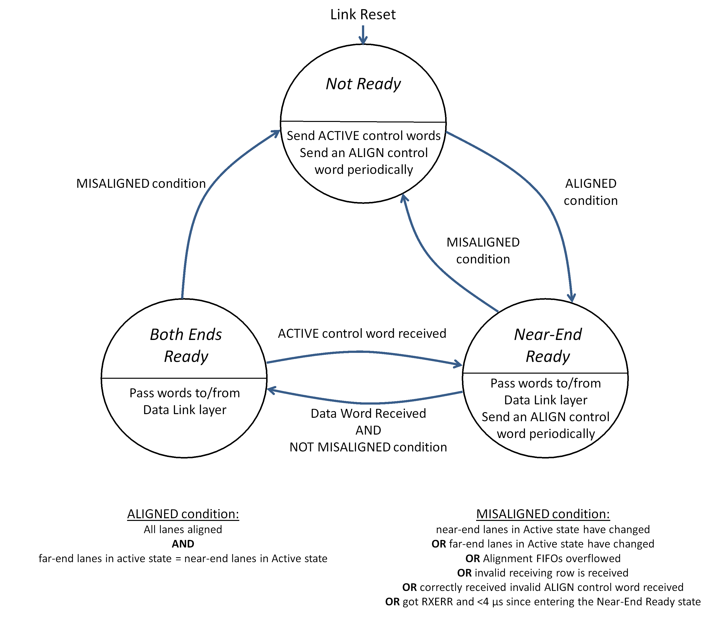 Figure 537: Alignment state machine
The Aligned condition shall arise when all of the following conditions occur:
- All lanes are aligned.
- The far-end lanes in the active state are the same as the near-end lanes in the active state.
Lane alignment is specified in requirement 5.6.6.4f.
The Misaligned condition shall arise when one or more of the following conditions occur:
- The near-end lanes in the Active state have changed.
- The far-end lanes in the Active state have changed.
- An alignment FIFO overflows.
- A correctly received, invalid ALIGN control word is received.
- An invalid receiving row is received.
- An RXERR occurs within 4 µs of entering the Near-End Ready state.
When the Near-End Ready state is entered it is important not to lose words, which are replaced by RXERR control words until the worst case round trip delay elapses, 4 µs with a 100 meter cable. After the round-trip delay time, the near-end receives words from the far-end that were generated after the far-end received the indication that the near-end is ready. Only then can it be allowed to receive RXERRs that possibly replace ACTIVE control words sent. Before that time, it is important to receive any ACTIVE control word sent by the far-end or get an RXERR and assume the worst case and move to Not Ready.
Not Ready state
The Alignment state machine shall enter the Not Ready state on one of the following conditions:
- Link Reset.
- From Near-End Ready state, when the Misaligned condition occurs.
- From the Both Ends Ready state, when the Misaligned condition occurs. When in the Not Ready state the Alignment state machine shall perform the following actions:
- Repeatedly send seven ACTIVE control words on all active lanes followed by one ALIGN control word on those lanes.
- Pass RXERR words to the Data Link layer.
No data words are sent in the Not Ready state.
The Alignment state machine shall leave the Not Ready state and move to the Near-End Ready state when the Aligned condition is fulfilled.
Near-End Ready state
The Alignment state machine shall enter the Near-End Ready state on one of the following conditions:
- From the Not Ready state, when the Aligned condition is fulfilled.
- From the Both Ends Ready state, when an ACTIVE control word is received. When in the Near-End Ready state the Alignment state machine shall perform the following actions:
- Receive data words and Data Link layer control words from the Data Link layer and pass them to the active lanes for sending.
- Receive data words and Data Link layer control words from the active lanes and pass them up to the Data Link layer.
- Repeatedly send one ALIGN control word every seven data or control words on each near-end, active lane. The Alignment state machine shall leave the Near-End Ready state on one of the following conditions, which are evaluated in the order given:
- When Link Reset is asserted, move to the Not Ready state.
- When the Misaligned condition occurs, move to the Not Ready state.
- When a data word is received in one or more lanes and the active lanes are aligned, NOT Misaligned, move to the Both-Ends Ready state.
Both-Ends Ready state
The Alignment state machine shall enter the Both-Ends Ready state from the Near-End Ready state, when all of the following conditions occur:
- A data word is received in one or more lanes.
- The active lanes are NOT Misaligned. When in the Both-Ends Ready state the Alignment state machine shall initiate the following actions:
- Receive data words and Data Link layer control words from the Data Link layer and pass them to the active lanes for sending.
- Receive data words and Data Link layer control words from the active lanes and pass them up to the Data Link layer.
ACTIVE or ALIGN control words are not sent in the Both-Ends Ready state.
The Alignment state machine shall leave the Both-Ends Ready state on one of the following conditions, which are evaluated in the order given:
- When Link Reset is asserted, move to the Not Ready state.
- When the Misaligned condition occurs, move to the Not Ready state.
- When an ACTIVE control word is received, move to the Near-End Ready state.
Asymmetric links
A link shall be able to have some lanes that are unidirectional, sending information in one direction only, provided that at least one lane is able to send information in both directions.
So that unidirectional lanes can be correctly initialised, each link containing one or more unidirectional lanes has at least one lane which is a bi-directional lane.
One end of a unidirectional link shall be transmit only and the other end of that link receive only.
A multi-lane link incorporating some unidirectional lanes is illustrated in Figure 538.
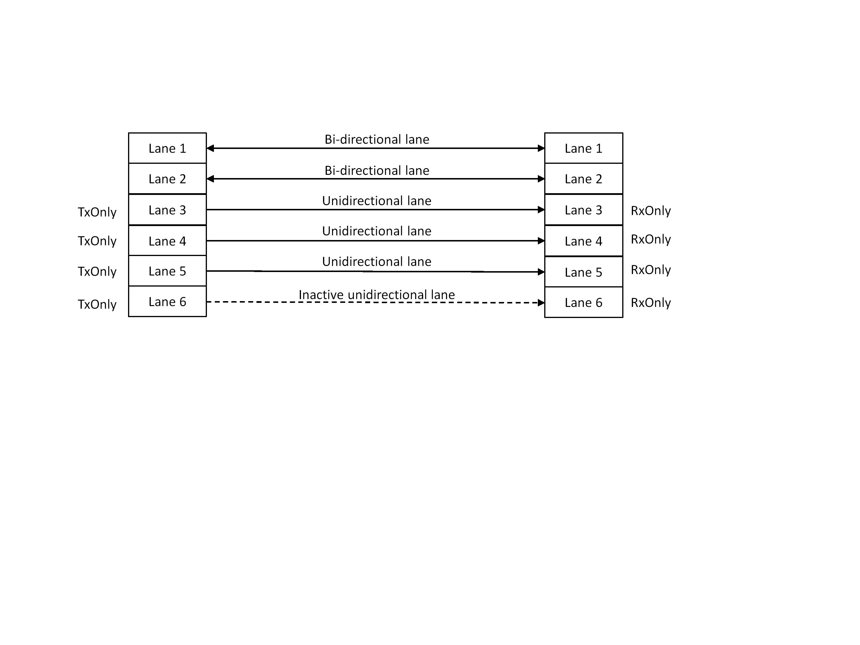 Figure 538: Multi-Lane link incorporating some unidirectional lanes
Each end of a lane shall have a send enable TxEn and receive enable RxEn management parameter with the following function:
- When TxEn = 1 and RxEn = 1 the end of the lane operates as a bi-directional lane.
- When TxEn = 1 and RxEn = 0, the end of the lane operates as a transmit only, unidirectional lane, sending from the end with the TxEn parameter set to 1.
- When TxEn = 0 and RxEn = 1, the end of the lane operates as a receive only, unidirectional lane, receiving data at the end with the RxEn parameter set to 1.
- When TxEn = 0 and RxEn = 0, the end of the lane is disabled and neither sends nor receives information.
Initialisation of unidirectional lanes
General
The ACTIVE control word shall be used to indicate to the far-end of a link, the lanes at the near-end which are in the Active state, with bit L of the ACT field in the ACTIVE control word indicating the state of lane L as follows:
- Bit L = 0, indicates that lane L is not in the Active state.
- Bit L = 1, indicates that lane L is in the Active state. The ACTIVE control word shall be sent by all bi-directional and transmit only lanes.
The ACTIVE control word is also used to indicate when an RxOnly lane has detected an error and exited the Active state so that the other end of the lane, that is a TxOnly lane, is notified and reset.
The Multi-Lane layer shall pass the following information to each lane in the Lane layer for use in initialising unidirectional lanes:
- TxOnly, which instructs the lane to operate as a transmit only lane.
- RxOnly, which instructs the lane to operate as a receive only lane.
- FarEndActive, which informs the lane initialisation state machine of a transmit only lane that the initialisation state machine at the far-end of the link has locked to the initialisation information and has reached the Active state.
FarEndActive
When a valid ACTIVE control word is received with bit L = 1, the FarEndActive corresponding to lane L shall be set to 1.
When a valid ACTIVE control word is received with bit L = 0, the FarEndActive corresponding to lane L shall be cleared to 0.
When the lane initialisation state machine for lane L is in the ClearLine state, the FarEndActive corresponding to lane L shall be cleared to 0.
TxOnly
TxOnly for lane L, TxOnly(L), shall be asserted when either of the following conditions occur:
- LaneState(L) is not ClearLine AND TxEn(L) = 1 AND RxEn(L) = 0.
- LaneState(L) = Started AND FarEndActive(L). TxOnly for lane L, TxOnly(L), shall be de-asserted when any of the following conditions occur:
- TxEn(L) = 0.
- RxEn(L) = 1.
- LaneState(L) = ClearLine.
RxOnly
RxOnly for lane L, RxOnly(L), shall be asserted when all of the following conditions occur:
- At least one bi-directional lane in the asymmetric, multi-lane link is in the Active state.
- TxEn(L) = 0 AND RxEn(L) = 1. RxOnly for lane L, RxOnly(L), shall be de-asserted when any of the following conditions occur:
- TxEn(L) = 1.
- RxEn(L) = 0.
LaneReset
The reset for lane L, LaneReset(L), shall be asserted when any of the following conditions occur:
- LinkReset is asserted.
- LaneState(L) = Active AND TxOnly(L) is asserted AND FarEndActive(L) is not asserted.
- LaneState(L) = Active AND TxOnly(L) is asserted AND there is not a bidirectional lane in active state. The reset for lane L, LaneReset(L), shall be de-asserted when the following condition occurs:
- LaneState(L) = ClearLine AND LinkReset is de-asserted.
Hot redundant lanes
To support rapid switching to a redundant lane in the event of a lane failure, it shall be permitted to include one or more hot redundant lanes in a multi-lane link.
The number of hot redundant lanes can be different on each side of the link. This is so that hot redundancy can be provided in asymmetric links.
A hot redundant lane shall initialise in the same way as a normal lane.
Once initialised a hot redundant lane shall send Lane layer and Multi-Lane layer control words, and not send any Data Link layer word.
If the number of active transmitting lanes is less than or equal to the value of the “maximum number of data-sending lanes” configuration parameter, all active transmitting lanes shall be data-sending lanes.
If the number of active transmitting lanes is greater than the value of the “maximum number of data-sending lanes” configuration parameter, the active transmitting lanes shall be configured as follows:
- The active transmitting lanes with the lowest lane numbers are data-sending lanes, where the number of data-sending lanes is the maximum specified in the “maximum number of data-sending lanes” configuration parameter.
- The other active transmitting lanes, with higher lane numbers, are hot redundant lanes. The Data Link layer shall only pass information to data-sending lanes.
- 1 A hot redundant lane is an active lane that is not a data-sending lane.
- 2 Data, Broadcast and Idle frames are not sent over the hot redundant lane, to simplify the logic needed for mapping the stream of data from the Data Link layer to the several lanes.
A hot redundant lane shall send a PRBS sequence with the polynomial and initial seed value specified in requirements 5.7.6.2.3b, 5.7.6.2.3c, 5.7.6.2.3d, unless it has Lane layer or Multi-Lane layer control words to send.
The PRBS minimises EM emissions.
Hot redundant lanes shall have higher lane numbers than active lanes that are not hot redundant.
When an ALIGN control word is sent by a hot redundant active lane, its fields LANES and iLANES shall be both set to zero.
This indicates that the lane is a hot redundant lane.
When an ALIGN control word is received by an active lane, that lane shall be a data-receiving lane, unless the LANES and iLANES fields of the ALIGN control word are both zero, in which case the lane is NOT a data-receiving lane.
Only lanes that are data-receiving lanes are permitted or expected to receive Data Link layer words. If a lane is not a data-receiving lane it means that the far-end of the lane is a hot redundant lane.
A lane that is NOT a data-receiving lane shall only act on the Lane layer and Multi-Lane layer control words it receives, and any other received word is discarded.
If the far-end of the lane is an active transmitting lane, it is a hot redundant lane. In this case, the PRBS words received are discarded.
When a data-sending lane fails and is disconnected, the Multi-Lane layer shall automatically promote the hot redundant lane with the lowest lane number to a data-sending lane.
- 1 This is much faster than activating a cold redundant lane which requires time for the lane to initialise.
- 2 When a data-sending lane fails, a new alignment occurs and the new ALIGN control words indicate to the far-end of the link which lanes are data-receiving lanes and are therefore expected to receive Data Link layer words.
Data Link layer
Data Link layer responsibilities
The Data Link layer shall manage the flow of information over the link, send and receive N-Chars and Fills, send and receive broadcast messages, provide quality of service, and, when possible, recover from errors that occur on the link.
The Data Link layer shall receive N-Chars and Fills and Broadcast Messages from the Network layer.
The Data Link layer shall pass N-Chars and Fills and Broadcast Messages to the Network layer.
The Data Link layer shall receive information identifying the current time-slot from the Network layer.
The Data Link layer shall pass data and control words to the Multi-Lane or Lane layer.
The Data Link layer shall receive data and control words from the Multi-Lane or Lane layer.
The Data Link layer shall control the Multi-Lane or Lane layer using the following signals:
- Link Reset, for the Multi-Lane layer.
- LaneReset, for the Lane layer.
The Data Link layer shall pass near-end capability control information to the Multi-Lane or Lane layer.
The Data Link layer shall receive far-end capability information, which is received in the INIT3 Capability field for each lane, from the Multi-Lane or Lane layer.
The Data Link layer shall be controlled by the following management parameters from the Management Information Base: - QoS parameters for each virtual channel.
- Normalised Expected Broadcast Bandwidth parameter.
- DataScrambled.
- Link Reset.
- Interface Reset.
Reset of a link can be commanded via the Management Information Base. The link reset can also be automatically executed when the other end indicates that it has been link reset.
The Data Link layer shall provide the following status information to the Management Information Base:
- Virtual channel status for each virtual channel.
- Error Information.
- FarEndLinkReset.
The interfaces to and from the Data Link layer are illustrated in Figure 539 and Figure 540.
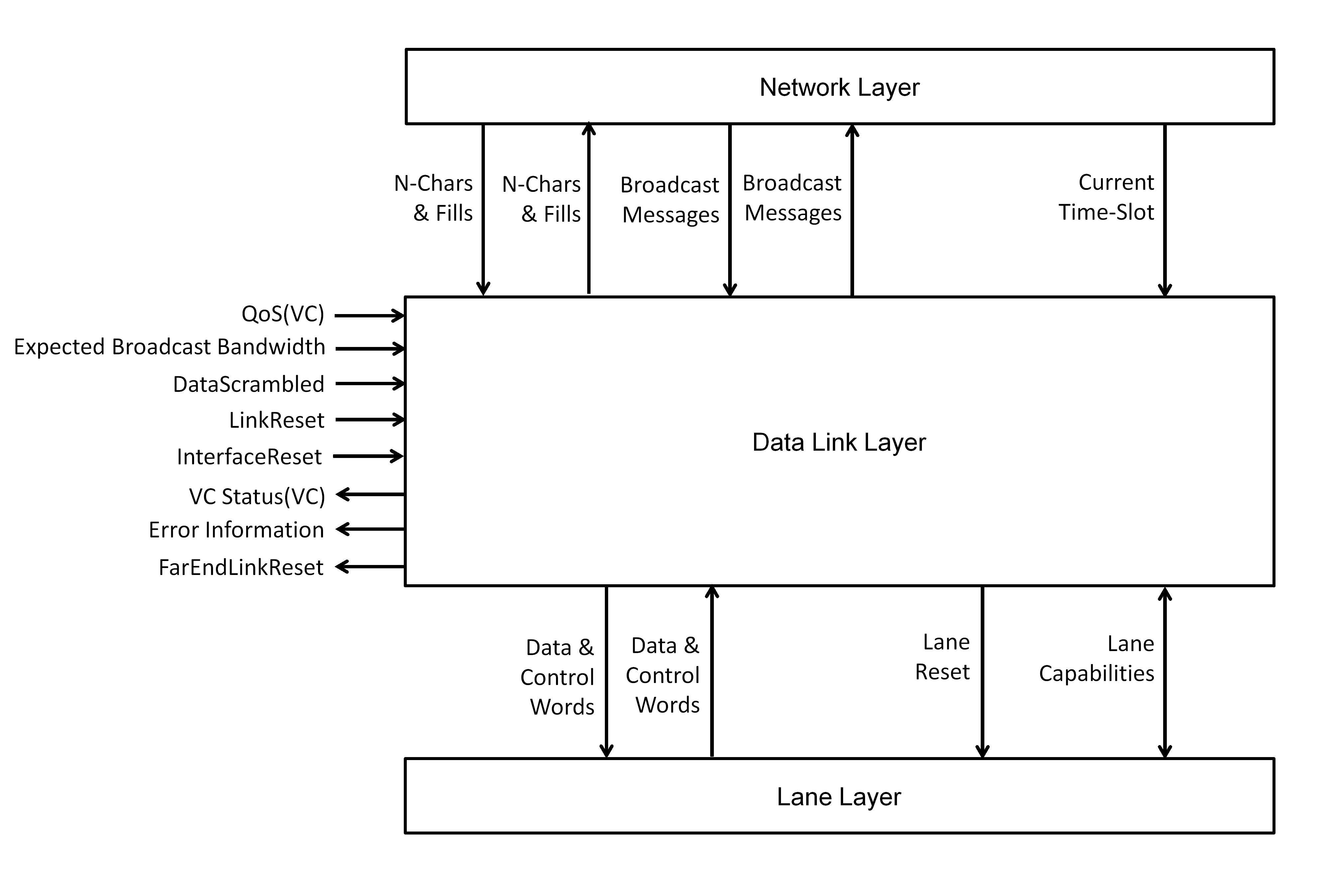 Figure 539: Interfaces to the Data Link layer for a single lane link
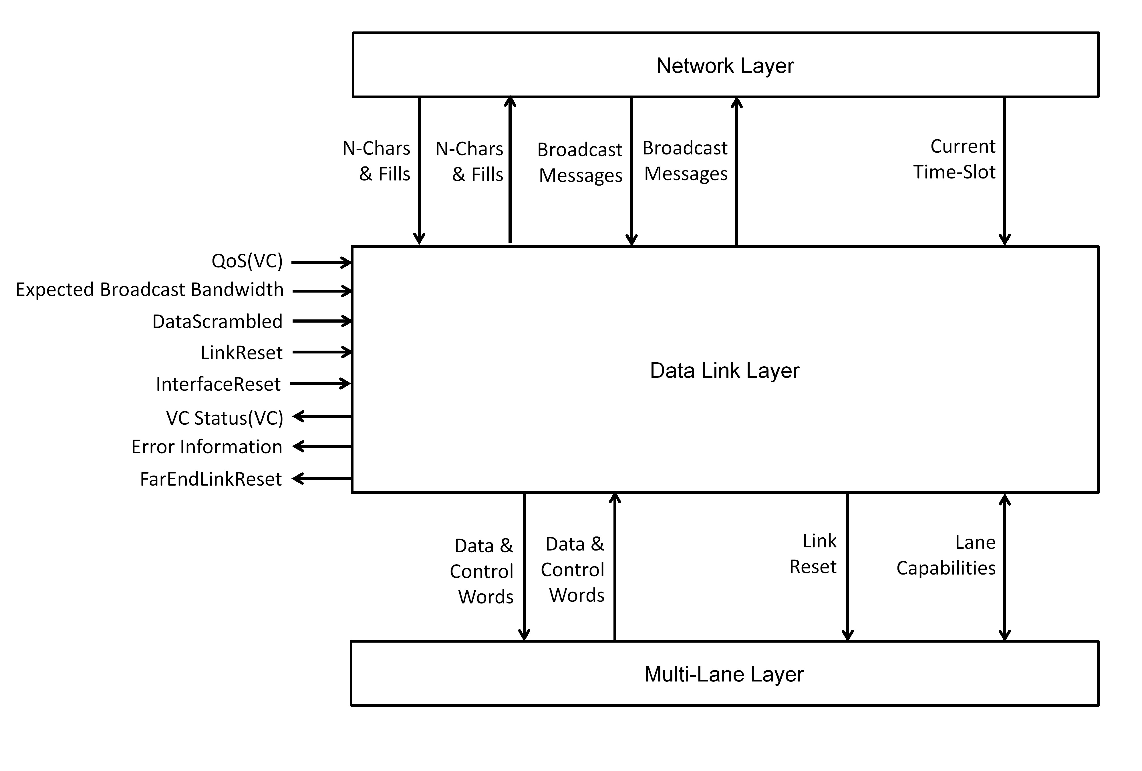 Figure 540: Interfaces to the Data Link layer for a multi-lane link
Virtual channels
General
The network layer interface to the SpaceFibre port shall comprise one or more output virtual channel buffers and one or more input virtual channel buffers.
Normally, there is the same number of output and input virtual channel buffers.
A SpaceFibre port shall have a maximum of 32 virtual channels.
Each virtual channel shall have a unique number in the range 0 to 31.
Virtual channel numbers 32 to 255 shall be reserved.
Virtual channels in a SpaceFibre port shall be numbered consecutively starting from zero.
A particular virtual channel shall be identified by its virtual channel number.
Each virtual channel should have an output virtual channel buffer and an input virtual channel buffer.
Output virtual channel buffer
An output virtual channel buffer should be large enough to hold at least 256 SpaceFibre N-Chars or Fills.
This corresponds to one full SpaceFibre data frame when using a single-lane link. To support high data rates or long cable lengths for a particular virtual channel, the size of the output virtual channel buffer is made larger. Normally, the buffer size is sufficient for at least 512 SpaceFibre N-Chars and Fills.
To send a SpaceFibre packet over a particular virtual channel, the Data Link layer shall accept the N-Chars and Fills forming the SpaceFibre packet from the Network layer, placing them into the virtual channel buffer, starting with the leading N-Chars or Fills of the SpaceFibre packet.
If the output virtual channel buffer becomes full, the Data Link layer shall not accept more N-Chars or Fills from the Network layer for that virtual channel, until there is more room in the output virtual channel buffer.
SpaceFibre packets can be any length. Packets greater than the size of the output virtual channel buffer cannot fit into the buffer and are written into the buffer when space is made available as data is read out and sent over the SpaceFibre link.
As soon as one SpaceFibre packet has been written into the output virtual channel buffer, the next SpaceFibre packet to be sent over that virtual channel shall start to be written to that output virtual channel buffer, provided that there is room in the output virtual channel buffer for at least one more N-Char or Fill.
This means that it is possible to have many small packets waiting for transmission in the output virtual channel buffer.
SpaceFibre packets shall be sent over a virtual channel in the order in which they are written into the output virtual channel buffer for that virtual channel.
N-Chars and Fills written into an output virtual channel buffer at one end of a SpaceFibre link shall be transferred via the SpaceFibre link to the input virtual channel buffer at the other end of the SpaceFibre link with the same virtual channel number.
When Link Reset is asserted, the following actions shall take place:
- All output virtual channel buffers are flushed.
- For each output virtual channel buffer, if the last character written by the user application was not an EOP, EEP or Fill, all new data characters are discarded up to and including the next EOP or EEP.
This is similar to SpaceWire error handling, which spills the current packet being transmitted when a disconnection error occurs. This ensures that the receiver does not get an incomplete packet with an invalid header.
A continuous mode of operation should be included which is activated individually for each virtual channel by a configuration parameter, Continuous Mode (VC).
When the virtual channel of the output virtual channel buffer is configured to be in continuous mode and either the buffer is going to become full, or there is no lane in the Active state and the buffer is not empty, the following actions shall take place:
- The output virtual channel buffer is flushed.
- An EEP is placed in the output virtual channel buffer.
- If the last character written by the user application was not an EOP, EEP or Fill, all new data characters are discarded up to and including the next EOP or EEP.
- 1 A virtual channel in continuous mode is always able to accept N-Chars and Fills from the Network layer and prevents packets from being stuck due to a lane failure, a persistent lack of space at the destination or an unexpected low bandwidth utilisation.
- 2 Loss of data could occur when a virtual channel is configured in continuous mode. In this case, newer data is considered more important than older data.
Input virtual channel buffers
When segments of SpaceFibre packets are received, they shall be placed in the input virtual channel buffer for the virtual channel that they were sent over.
SpaceFibre N-Chars appear in an input virtual channel buffer in the same order in which they were written into the corresponding output virtual channel buffer at the other end of the link.
An input virtual channel buffer shall be large enough to hold at least 256 SpaceFibre N-Chars or Fills.
This value is implementation dependent. To support high data rates or long cable lengths for a particular virtual channel, the size of the input virtual channel buffer is made larger. Normally, the buffer size is sufficient for at least 1024 SpaceFibre N-Chars and Fills.
When there are N-Chars available in an input virtual channel buffer, the Data Link layer shall inform the Network layer that there is data available to read from that input virtual channel buffer.
When Link Reset is asserted, the following actions shall take place:
- All input virtual channel buffers are flushed.
- If the last character read from an input virtual channel buffer was not an EOP, EEP or Fill character, an EEP is the next character read from the input virtual channel buffer.
This is equivalent to SpaceWire error handling, which uses the EEP to indicate at the receiver side that the link was disconnected and that the last packet provided was incomplete and in error.
Flow control
Output virtual channel flow control
Each output virtual channel buffer shall keep track of the space available in the corresponding input virtual channel at the far-end using an FCT credit counter, which indicates how much more data it is permitted to send.
An output virtual channel buffer shall indicate to the medium access controller that it has a data segment ready to send when both of the following conditions are fulfilled:
- The FCT credit counter is greater than zero.
- The output virtual channel buffer contains N×64 data words or it contains an EOP or EEP, or it is full, where N×64 is the maximum number of data words allowed in a data frame for that virtual channel and N is an integer less than or equal to the "maximum number of data-sending lanes" parameter.
See clause 5.3.8.2 for further information on the data frame.
When a host is able to provide words continuously at the full transmit rate with no gaps, the host may inform an output virtual channel buffer of this condition and the output virtual channel buffer then indicates to the medium access controller that it has frames ready to send.
This allows the latency to be reduced when a continuous stream of packets or a large packet is sent.
When informed that it is now permitted to send another data segment over the SpaceFibre link, an output virtual channel buffer shall pass up to N×64 data words to the medium access controller for sending over the SpaceFibre link, where N is an integer less than or equal to the "maximum number of data-sending lanes" parameter.
If the port between the SpaceFibre interface and the host system is larger than 32 data bits, more Fills can be needed for filling to maintain packet cargo word alignment.
On LinkReset, the FCT credit counter shall be set to zero.
On LaneReset, the FCT credit counter shall not be modified.
When an FCT is received for a particular virtual channel, M×64 shall be added to the FCT credit counter for that virtual channel, where M is the value of the Multiplier field in the FCT plus 1.
The FCT indicates that the virtual channel buffer at the far-end of the link is able to accept another M×64 data words, see clause 5.3.5.2.
When a data segment is sent by a particular virtual channel to the medium access controller, the number of data words sent shall be subtracted from the FCT credit counter.
If the FCT credit counter overflows, the FCT credit counter shall remain unchanged, saturated to its maximum value, and the error reported in a status register.
The size of the FCT credit counter shall be at least 1×64×M, corresponding to one FCT.
The size of the FCT credit counter should be at least 4×64×M, corresponding to four FCTs.
At 2,5 Gbit/s data signalling rate a 4×64×M buffer allows the maximum data rate to be achieved over 100 m with that virtual channel. At 6,25 Gbit/s six FCTs are needed.
Input virtual channel flow control
When a data segment is received, the data words it contains shall be placed in the appropriate input virtual channel buffer.
An input virtual channel buffer shall request an FCT to be sent after LinkReset for each M×64 data words of space in the input virtual channel buffer, where M is the value of the Multiplier field in the FCT plus 1.
After link reset this can result in several FCTs being sent for a virtual channel, if its input buffer can hold more than M×64 data words, see clause 5.3.5.2.
An input virtual channel buffer shall request an FCT to be sent when the network layer reads M×64 data words from the input virtual channel buffer, where M is the value of the Multiplier field in the FCT plus 1.
- 1 These M×64 data words can be read over a period of time, i.e. not all at the same time.
- 2 If a frame contains an EOP or EEP, it is possible that as well as N-Chars it contains some Fills which are used to pad out the number of N-Chars to a multiple of four, i.e. complete data word. At the link level these Fills are treated in the same way as N-Chars and are transferred across the link and placed in the input virtual channel buffer at the far-end of the link.
- 3 An FCT is effectively exchanged for M×64 data words, where M is the value of the Multiplier field in the FCT plus 1, see clause 5.3.5.2.
- 4 When there are more than 8 lanes in a multi-lane link, two FCTs are sent because the FCT multiplier, see 5.3.4.2e, has a maximum value of 8. This means the protocol overhead increases slightly when there are more than 8 lanes in a link.
When FCTs are being requested to be sent simultaneously for several different virtual channel buffers, they shall be arbitrated fairly.
If an input virtual channel buffer overflows, the SpaceFibre link shall be reset and an error reported.
An input virtual channel buffer should never overflow. This condition indicates a fatal error for which the only option is to reset the link.
Medium access controller
Medium access control
A medium access controller shall determine which virtual channel is allowed to send the next data segment.
Only output virtual channel buffers indicating that they have data ready to form a data segment, shall be permitted to compete for sending the next data segment.
Only virtual channels whose FCT credit counter indicates that its input virtual channel buffer at the far-end of the SpaceFibre link has room to accept the data words to be sent in the next data segment shall be permitted to compete for sending the next data segment.
Each output virtual channel buffer, with data words ready to send in its output virtual channel buffer and space available in its input virtual channel buffer at the far-end of the SpaceFibre link, a ready virtual channel, shall compete for sending the next data segment, if it is allowed to do so in the current time-slot.
Clause 5.7.4.3 provides details of time-slots and permission to send in a time-slot.
Quality of service
Each virtual channel shall support the following qualities of service: priority, bandwidth reservation and scheduled.
When hardware resources are extremely limited and there are no more than two virtual channels in a link, bandwidth reservation or scheduled QoS may be not supported.
This limits the usefulness and interoperability of the device and means that babbling node protection is not provided.
The quality of service parameters of each virtual channel shall be able to be set individually so that different qualities of service can be applied to different virtual channels.
Scheduled QoS
Time shall be split into 64 time-slots of equal duration specified at the system level.
Typical time-slot duration is in the range 100 μs to 16 ms and is application dependent. The number of time-slots, 64, is backwards compatible with SpaceWire time-codes.
The network layer shall provide an indication of when one time-slot finishes and the next one starts, together with the number of that time-slot.
In this way, the network layer is able to synchronise the scheduled QoS in each routing switch or node.
The schedule shall indicate in which time-slots a particular virtual channel is permitted to send data frames.
For each virtual channel there is a list of time-slots in which it is allowed to send data.
Several virtual channels shall be able to be scheduled to send data in the same time-slot.
If two or more virtual channels are scheduled to send data in the same time-slot, the medium access controller shall send data from the virtual channel with the highest precedence
See clause 5.7.4.4 for information on precedence.
When a time-slot starts, for which a specific virtual channel is scheduled to send data, has data ready to send in its output virtual channel buffer and has space in its input virtual channel buffer at the far-end of the SpaceFibre link, it shall compete with other virtual channels for sending data frames over the link based on its precedence.
A virtual channel that is not scheduled in the current time-slot shall not be allowed to compete for sending data over the link.
At the end of the time-slot, any virtual channel sending data segments shall cease sending them after the current data segment has been sent, unless that particular virtual channel buffer is also scheduled to send data in the next time-slot.
The scheduling of traffic from virtual channels over the SpaceFibre link has to leave room for any data segment left to be sent over the link from the previous time-slot, i.e. started being sent but not finished before the end of the time-slot.
When a SpaceFibre network is not needed to use the scheduling quality of service, the schedule for each virtual channel shall be set to use all time-slots.
Precedence
A virtual channel shall compete with other virtual channels for sending segments over the link, based on the current precedence of the virtual channel and its schedule.
The medium access controller shall use the precedence of each virtual channel to determine which ready virtual channel is permitted to send a data segment.
The precedence of the virtual channels shall be compared when the last word of the previous data segment is being read from the output virtual channel buffer by the medium access controller.
The virtual channel buffer that is ready and which has the highest precedence shall be permitted to send the next data segment.
The precedence of a virtual channel shall be determined by its quality of service parameters and its bandwidth credit.
The precedence of a virtual channel shall be calculated as the sum of the priority precedence plus the current value of bandwidth credit for that virtual channel.
- 1 Precedence = Priority Precedence + Bandwidth Credit
- 2 The priority precedence for a virtual channel is derived directly from its priority level parameter.
- 3 Precedence is calculated taking into account the quality of service mechanisms outlined in Table 534.
- 4 If the bandwidth credit is below the Minimum Bandwidth Credit Threshold, the Priority Precedence is set to zero, see clause 5.7.4.5.
Table 534: Precedence for different qualities of service
|
Quality of Service
|
Precedence
|
|
Priority
|
A priority virtual channel is normally only allowed to send data when no other virtual channel with a higher priority setting is ready to send data.
|
|
Bandwidth Reserved
|
Bandwidth reservation determines the precedence of a virtual channel based on the link bandwidth reserved for that virtual channel and its recent link utilisation.
|
|
Scheduled
|
Scheduled quality of service provides a means of ensuring fully deterministic allocation of SpaceFibre network resources.
|
Bandwidth credit
Each output virtual channel shall maintain a measurement of the Bandwidth Credit for that virtual channel.
The Bandwidth Credit shall be updated every time a data segment has been sent on any virtual channel.
If no data segment is sent, the Bandwidth Credit shall be updated after an interval approximately equal to the time it takes to send a full data frame, or less.
When no data is sent the Used Bandwidth is zero, see requirement 5.7.4.5g.
The Available Bandwidth shall be measured for the SpaceFibre link as the number of data or control words sent over the SpaceFibre link from all virtual channels, since the Bandwidth Credit was last updated.
When specifying a bandwidth allocation for a virtual channel, it is useful to think in terms of the percentage of overall link capacity being allocated. It is then straightforward to allocate a percentage of the bandwidth to each virtual channel, leaving some spare capacity for possible broadcast messages and general contingency. When setting the bandwidth allocations each virtual channel is allocated a little bit more bandwidth than it is expected to use, so that the counter is nominally saturated, and the sum of all virtual channel bandwidth allocations is less than 100%, to leave some margin for broadcasts, ACKs, FCTs, etc.
A virtual channel shall be allocated a portion of the Link Bandwidth that it expects to use, its Normalised Expected Bandwidth, which includes the overhead due to the use of frame delimiters and other control words.
- 1 This information is provided, using management parameters, for all virtual channels regardless of the quality of service they are providing.
- 2 The Normalised Expected Bandwidth assigned to each virtual channel has to account for any protocol overhead. When data is being sent in one direction only, the transmit side sends SDF-DATA-EDF, the receive side sends FCT-ACK, the transmit side replies with an ACK to the receive side FCT. This means that the best-case protocol overhead for unidirectional transmission is: 2+1/64+2+1 ~ 4% or 64/64+2+1 ~ 96% of effective bandwidth. For a link with a data signalling rate of 2,5 Gbit/s this results in a maximum user data throughput of 1,91 Gbit/s. When data is being sent in both directions at the same time, the transmit side sends the following control words in addition to those sent over a unidirectional link: an ACK for the receive-side data frame and its corresponding FCT to allocate more data space. This means that the best-case protocol overhead for bidirectional transmission is: 2+1+2/64+2+1+2 ~ 7% or 64/64+2+1+2 ~ 93% of effective bandwidth. For a link with a data signalling rate of 2,5 Gbit/s this results in a maximum user data throughput of 1,86 Gbit/s. When sending small data frames or many broadcast messages, the overhead can be higher.
Used Bandwidth shall be the number of data frame words sent by a particular virtual channel, including frame delimiters, since the last time the Bandwidth Credit was updated.
This is zero for all virtual channels except for the one that sent a data frame.
Bandwidth Credit shall be calculated independently for each virtual channel as follows:
![]() where
where ![]() is summation over previous frames or words, n is an integer representing the series of frames or words sent previously, and c is the virtual channel number of the virtual channel for which BandwidthCredit is being calculated.
is summation over previous frames or words, n is an integer representing the series of frames or words sent previously, and c is the virtual channel number of the virtual channel for which BandwidthCredit is being calculated.
The Bandwidth Credit value obtained by this formula saturates at plus or minus the Bandwidth Credit Limit, see requirement 5.7.4.5j. This means that the Bandwidth Credit represents the recent history of the virtual channel utilisation.
When there is an advantage to be gained in efficiency, another method of determining the bandwidth credit may be used provided that it gives equivalent results as 5.7.4.5g.
When the Normalised Expected Bandwidth is zero, the virtual channel shall not be permitted to send any data.
Bandwidth Credit shall be permitted to go negative.
A negative value indicates that the virtual channel is using more than its expected amount of link bandwidth.
Bandwidth Credit shall saturate at plus or minus the Bandwidth Credit Limit.
- 1 Therefore, when the Bandwidth Credit exceeds the Bandwidth Credit Limit, it is set to the value of the Bandwidth Credit Limit.
- 2 The specific value of the Bandwidth Credit Limit is implementation dependent. If the Bandwidth Credit Limit was set to the Link Bandwidth, that virtual channel reaches positive saturation after 1 second when no data is being sent by that virtual channel. After this period of time no further credit is given to the virtual channel until its Bandwidth Credit drops below the limit. Setting the Bandwidth Credit limit to Link Bandwidth/1000 means that the virtual channel starts to forget how much data it has sent after 1 ms. This gives a less accurate measurement of Bandwidth Credit, but requires counters with fewer bits. It makes the overuse mechanism kick in earlier.
When the Bandwidth Credit for a virtual channel reaches the Positive Bandwidth Credit Limit and stays at that value for at least the Virtual Channel Idle Time Limit, the virtual channel shall indicate in a status register that it is idle and using much less bandwidth than expected. - 1 A network management application is able to use this information to check correct utilization of link bandwidth by its various virtual channels.
- 2 The Virtual Channel Idle Time Limit is a configuration parameter that applies to all virtual channels. A typical value is 1 ms.
A Minimum Bandwidth Credit Threshold shall be set, below which a virtual channel is deemed to be using more than its allocated bandwidth.
The Minimum Bandwidth Credit Threshold shall be set at approximately 90 % of the value of the Negative Bandwidth Credit Limit.
When the Bandwidth Credit for a virtual channel reaches the Minimum Bandwidth Credit Threshold it shall indicate in a status register that the virtual channel is using more bandwidth than expected.
When the Bandwidth Credit value for a virtual channel is below the Minimum Bandwidth Credit Threshold, it shall temporarily set the priority precedence of that virtual channel to zero, until its Bandwidth Credit value goes above the minimum bandwidth credit threshold.
This prevents a virtual channel with high priority from hogging much more bandwidth that it is expected to use.
Bandwidth Credit shall be set to zero on interface reset.
Upon interface reset, the Normalised Expected Bandwidth for virtual channel zero, VC0, shall be set to approximately 10% and all the other virtual channels set to their minimum value.
- 1 After interface reset the local application or a remote application can set the Normalised Expected Bandwidth of each virtual channel as needed.
- 2 Virtual channel zero, VC0, is used for configuration, control and monitoring of the SpaceFibre network. See requirements 5.8.3z, 5.8.3aa, 5.8.3bb
Priority
A SpaceFibre port shall support Q priority levels numbered 0 to Q-1, where 0 is the priority level with the highest precedence.
A SpaceFibre port shall have a minimum of four priority levels: 0 to 3, where priority level 0 has the highest precedence and 3 has the lowest precedence.
A SpaceFibre port may support more than four priority levels.
Each priority level shall have a Priority Precedence value of 2B(Q1R)+B, where Q is the number of priority levels, R is the priority level, and B is equal to the Bandwidth Credit Limit.
- 1 Precedence = Priority Precedence + Bandwidth Credit
- 2 A precedence at one priority level cannot overlap with that of an adjacent priority level, regardless of the current Bandwidth Credit value.
- 3 For example in an implementation with 16 priority levels, priority level 15 has a Priority Precedence value of B, priority level 14 has a Priority Precedence value of 3B, and priority level 0 has a Priority Precedence value of 31B.
Each virtual channel shall be able to be assigned any of the priority levels.
More than one virtual channel shall be able to be set to the same priority level.
When more than one virtual channel has the same priority level, the one with the highest Bandwidth Credit value shall have the highest precedence.
Upon interface reset, the quality of service for each virtual channel shall be set to lowest priority.
Integrated quality of service
When a particular time-slot arrives, virtual channels that are scheduled to send data in that particular time-slot and are ready to send, shall compete with other virtual channels that are also scheduled to send in that time-slot, based on their precedence.
When a particular time-slot arrives, virtual channels that are scheduled to send data in that particular time-slot, are ready to send, and have the same Priority Precedence, compete based only on the bandwidth credit of that virtual channel. If all virtual channels use the same priority level, bandwidth reserved quality of service is used. If a virtual channel exceeds its allocated bandwidth, babbling node protection sets its priority to the lowest level.
Broadcast flow control
A Broadcast Bandwidth Credit Counter shall be associated with the broadcast mechanism to monitor and limit the amount of link bandwidth used by broadcast messages.
The medium access controller shall have one Broadcast Bandwidth Credit Counter for all the broadcast channels.
The Broadcast Bandwidth Credit Counter shall monitor and control the aggregate bandwidth of all the broadcast channels.
On link reset the Broadcast Bandwidth Credit Counter shall be set to zero.
The Broadcast Bandwidth Credit Counter shall be decreased by one every time a broadcast frame has been sent.
The broadcast frame has a fixed size of four words so for the Broadcast Bandwidth Credit the measurement unit is 4 words or a broadcast frame.
A management parameter, called the Normalised Expected Broadcast Bandwidth, shall specify a portion of the Link Bandwidth that is reserved for the broadcast messages, including the overhead of the broadcast frame delimiters.
The Broadcast Bandwidth Credit Counter shall saturate at the Broadcast Bandwidth Credit Limit.
Therefore, when the Broadcast Bandwidth Credit exceeds the Broadcast Bandwidth Credit Limit, it is set to the value of the Broadcast Bandwidth Credit Limit.
The Broadcast Bandwidth Credit Limit shall be a constant set to 256 broadcast frames.
This allows up to 256 broadcast messages to be sent by a broadcast channel before it is inhibited, preventing broadcast messages being sent until more credit has been accumulated. 256 broadcast frames is 1024 words.
The Broadcast Bandwidth Credit Counter shall never be allowed to go negative.
When the Broadcast Bandwidth Credit Counter is zero, no broadcast frames shall be sent.
The Broadcast Bandwidth Credit shall be increased by one after the interval equal to the time it takes to send the number of words of 4 divided by the Normalised Expected Broadcast Bandwidth.
Framing
Data encapsulation
Data segments shall be encapsulated in a data frame with an SDF being added before the data segment and an EDF being added afterwards, prior to them being passed to the Lane or Multi-Lane layer.
Broadcast messages shall be encapsulated in a broadcast frame with an SBF being added before the broadcast message and an EBF being added afterwards, prior to them being passed to the Lane or Multi-Lane layer.
When a link reset condition occurs, the current data frame or broadcast frame shall stop being passed to the Lane or Multi-Lane layer and a new data frame or broadcast frame started.
EM emission mitigation
Data scrambling
When the DataScrambled management parameter is set, the data words of data frames shall be scrambled prior to transmission of the frame by bit-wise multiplication of the data with a sequence of random numbers produced from a scrambling polynomial.
- 1 Bit-wise multiplication is the XOR function.
- 2 This scrambler belongs to the family of the additive scramblers. The scrambler is illustrated in Figure 541, which is included for clarity. The scrambler can be implemented in other ways.
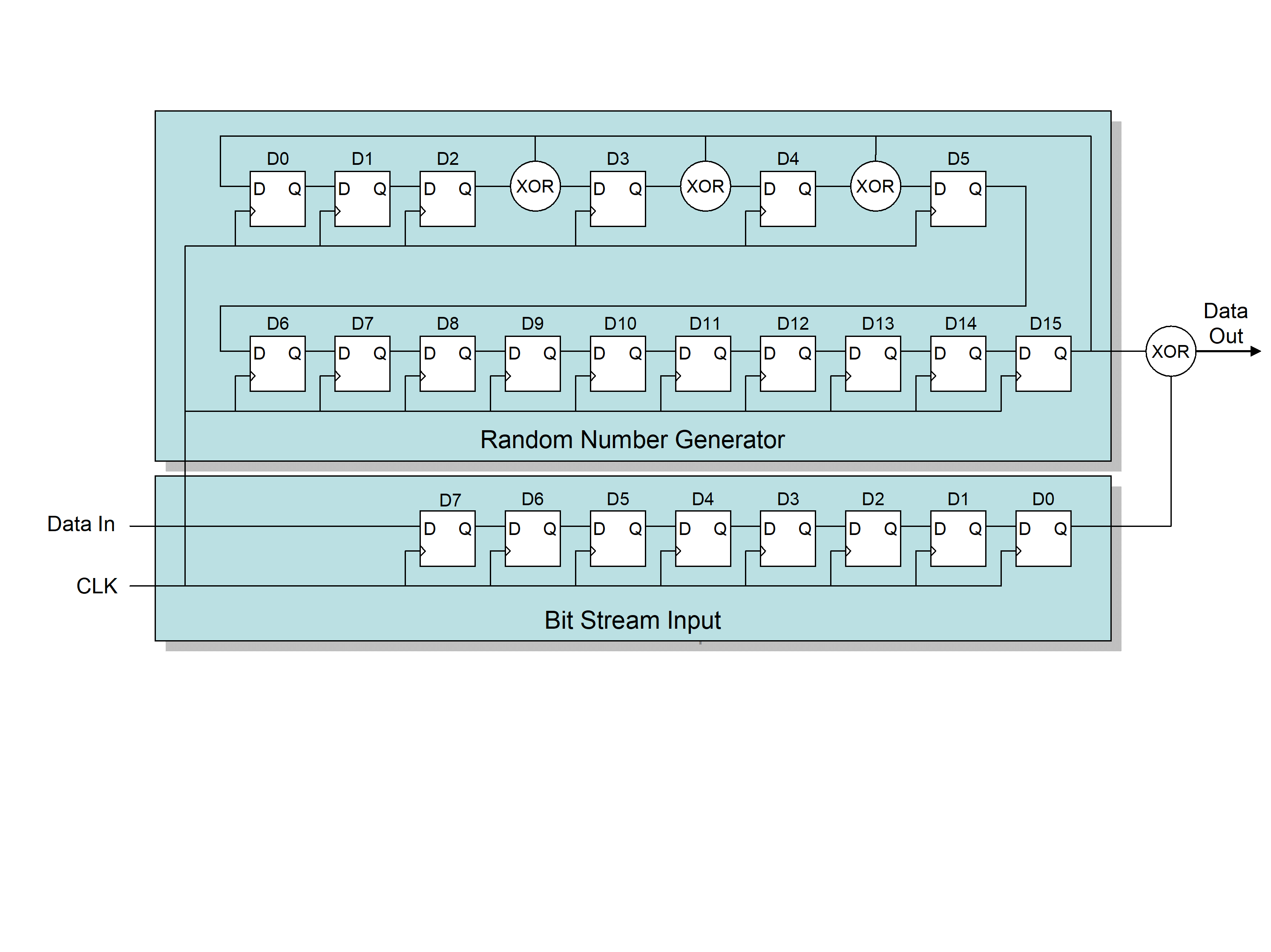 Figure 541: Scrambler / de-scrambler
The scrambling polynomial to use shall be G(x) = X16 + X5 + X4+ X3+ 1.
The seed for the scrambler shall be 0xFFFF.
0xFFFF results in all flip-flops in the random number generator being set to one.
The scrambler shall be re-seeded at the start of every new data frame.
The single bit output sequence from the random number generator shall be XORed with the bit sequence from the data word.
The random number generator only generates bits when there are data bits to be scrambled, i.e. the random number generator stops when no data is being XORed. For example, when an FCT is interleaved within a data frame, the random number generator only runs for the data in the data frame.
The least-significant bit of the least-significant character in each word shall be scrambled first.
When an EOP or EEP or Fill occurs in the data it shall not be replaced by scrambled data, although the random number generator continues to generate random numbers normally as if the EOP or EEP or Fill were a data character.
- 1 If the data value is scrambled while maintaining the K-flag, invalid K-codes are generated from the EOP/EEP/Fill characters. Scrambling of a K-code is likely to result in an invalid K-code which cannot be encoded by the 8B/10B encoder.
- 2 Figure 542 shows an example of a not scrambled data frame and the corresponding scrambled data frame. The top table shows the not scrambled data frame and bottom table shows the corresponding scrambled data frame. When data is scrambled the CRC is calculated on the scrambled data.
|
0 7
|
8 15
|
16 23
|
24 31
|
|
COMMA
|
SDF
|
0x00
|
0x00
|
|
0x00
|
0x01
|
0x02
|
0x03
|
|
0x04
|
0x05
|
0x06
|
0x07
|
|
0x08
|
EOP
|
Fill
|
Fill
|
|
EDF
|
0x22
|
0x28
|
0xA8
|
|
Original (not scrambled) data frame
| |||
|
0 7
|
8 15
|
16 23
|
24 31
|
|
COMMA
|
SDF
|
0x00
|
0x00
|
|
0xFF
|
0x16
|
0xC2
|
0x17
|
|
0xB6
|
0xE2
|
0x04
|
0x85
|
|
0x7A
|
EOP
|
Fill
|
Fill
|
|
EDF
|
0x22
|
0x98
|
0xDA
|
|
Scrambled data frame
| |||
Figure 542: Example of scrambling of a short data frame
Data Unscrambling
When data frames are received and the INIT3DataScrambled flag from the Lane layer is set, indicating that the data received is scrambled, the data shall be unscrambled by multiplying, XORing, the received data with the same scrambling sequence as was used for scrambling.
The control characters representing EOP or EEP or Fill shall not be unscrambled.
Idle frame scrambling
The PRBS field of idle frames shall be filled with a pseudo-random bit sequence produced from a pseudo-random bit sequence generation polynomial.
This PRBS sequence spreads the EM emission spectrum from the idle frames. It can also be used to help measure transmitter and receiver eye patterns when the lane is idle and just sending idle frames.
When a new idle frame is started, the PRBS generator for idle frames shall not be re-seeded.
The pseudo-random bit sequence generation polynomial to use shall be
On link reset, the initial seed for the PRBS generator shall be 0xFFFF.
0xFFFF results in all flip-flops in the random number generator being set to one.
The initial seed value 0xFFFF shall be used to calculate the first idle word after link reset.
After link reset, the first idle frame contains the values specified in Figure 543.
|
BYTE 1
|
BYTE 2
|
BYTE 3
|
BYTE 4
|
|
COMMA
|
SIF
|
SEQ_NUM
|
CRC
|
|
0xFF
|
0x17
|
0xC0
|
0x14
|
|
0xB2
|
0xE7
|
0x02
|
0x82
|
|
0x72
|
0x6E
|
0x28
|
0xA6
|
Figure 543: Effect of scrambling on an idle frame
The single bit output sequence from the random number generator shall form the PRBS in the idle frame.
The least-significant bit of the least-significant character in each word shall be filled with PRBS first.
The random number generator shall stop temporarily when a control word is embedded in the idle frame.
For example, when an FCT is embedded in the idle frame.
A PRBS field in an idle frame which does not follow the needed PRBS sequence shall not cause an error.
Sequence Numbering
Sequence Numbers on transmission
A single 7-bit Transmit Sequence Counter shall be maintained in the transmit side of the SpaceFibre port to hold the 7-bit Sequence Count in the SEQ_NUM of the last data frame, broadcast frame or FCT control word that was sent.
The 7-bit Transmit Sequence Counter shall operate modulo 128.
A Transmit Polarity Flag shall be associated with the 7-bit Transmit Sequence Counter together forming the Sequence Number, SEQ_NUM.
See clause 5.7.7.3 for information on the Transmit Polarity Flag and what it is used for.
The Transmit Sequence Counter shall be cleared to zero on link reset of the SpaceFibre port.
The Transmit Polarity Flag shall be cleared to zero on link reset of the SpaceFibre port.
The Transmit Polarity Flag shall be inverted each time a new error recovery operation begins.
The Transmit Sequence Counter and associated polarity flag shall provide Sequence Numbers for data frames, FCTs, broadcast frames, idle frames and FULL words.
Immediately prior to an end of data frame, end of broadcast frame, or FCT control word being passed from the Data Link layer to the Lane layer, or to the Multi-Lane layer, the current value of the Transmit Sequence Counter shall be incremented and the new value together with the current value of the polarity flag placed in the Sequence Number, SEQ_NUM, field of the end of data frame, end of broadcast frame, or FCT control word.
- 1 Every 128 sequence numbers the counter rolls over repeating the series of sequence numbers.
- 2 The first frame, typically an FCT, sent after link reset has SEQ_NUM set to +1 because of this clause, i.e. the Sequence Counter is reset to zero and then incremented to +1 immediately before the EDF, EBF, or FCT is sent.
When a FULL control word or an idle frame is passed from the Data Link layer to the Lane layer, or to the Multi-Lane layer, the current value of the Transmit Sequence Counter together with the current value of the polarity flag shall be placed in the Sequence Number, SEQ_NUM, field of the start of idle frame, SIF or FULL control word.
Sequence Numbers on reception
A single 7-bit Receive Sequence Counter shall be maintained in the receive side of the SpaceFibre port to hold the 7-bit Sequence Count in the SEQ_NUM of the last data frame, broadcast frame or FCT control word that was received correctly.
The 7-bit Receive Sequence Counter shall operate modulo 128.
A Receive Polarity Flag together with the 7-bit Receive Sequence Counter form the Receive Sequence Number, the value of which shall be checked against received Sequence Numbers, SEQ_NUM.
The Receive Polarity Flag shall be determined by the Receive Error state machine.
The Receive Sequence Counter shall be cleared to zero on link reset of the SpaceFibre port.
The Receive Polarity Flag shall be cleared to zero on link reset of the SpaceFibre port.
The Receive Sequence Counter shall not be modified on LaneReset of the SpaceFibre port.
The Receive Polarity Flag shall not be modified on LaneReset of the SpaceFibre port.
The 7-bit Receive Sequence Counter together with the Receive Polarity Flag shall be used to check the sequence numbers of data frames, FCTs broadcast frames, idle frames and FULL control words.
When an EDF, EBF, SIF, FCT, or FULL control word with a valid CRC passes into the Data Link layer from the Lane or Multi-Lane layer, its Sequence Number, SEQ_NUM, shall be checked against the current value of the Receive Sequence Counter and Receive Polarity Flag.
If the Sequence Count of the SEQ_NUM of a received EDF, EBF or FCT is one more than the Receive Sequence Counter and the polarity flag of the SEQ_NUM matches the Receive Polarity Flag, the data frame, broadcast frame or FCT shall be accepted.
If the Sequence Number, SEQ_NUM, of a received SIF or FULL has the same value as the Receive Sequence Counter and the polarity flag of the SEQ_NUM matches the Receive Polarity Flag, the idle frame or FULL shall be accepted.
An idle or FULL frame carries the Sequence Number of the last data frame, broadcast frame or FCT transmitted.
When a data frame, FCT or broadcast frame is accepted, the Receive Sequence Counter shall be incremented.
If the Sequence Count of the SEQ_NUM of a received EDF, EBF or FCT is not one more than the Receive Sequence Counter or the polarity flag of the SEQ_NUM is not the same as the Receive Polarity Flag, a sequence error has occurred and the data frame, FCT or broadcast frame shall be discarded.
A sequence error occurs when the Sequence Count in a SEQ_NUM of a data frame, broadcast frame or FCT is not one more, using modulo 128 arithmetic, than the value in the Receive Sequence Counter or the polarity flag is different. It also occurs when the Sequence Number of an idle frame or FULL control word does not match the value of the Receive Sequence Number. See clause 5.7.7.2.2 for information on what happens when a sequence error occurs. See clause 5.7.7.3 for more information about the value of the polarity flag of the Receive Sequence Number.
If the Sequence Count of the SEQ_NUM of a received SIF or FULL is not the same as the Receive Sequence Counter or the polarity flag of the SEQ_NUM is not the same as the Receive Polarity Flag, a sequence error has occurred and the idle frame or FULL shall be discarded.
When a data frame, FCT or broadcast frame is discarded, the Receive Sequence Counter shall not be incremented.
CRC for data frame
A 16-bit CRC checksum shall be applied to data frames.
A single bit error on the line does not result in a CRC error in the data frame because an RXERR occurs and the data frame is discarded before the CRC is checked. A CRC error in a data frame therefore indicates that a multi-bit error occurred. See requirement 5.5.7j It is possible that a disparity error in a frame is not detected until the word following an EDF. The word where the disparity error is detected and the previous word, i.e. the EDF, are both set to RXERR, see requirement 5.5.7l, so the single bit error in a data frame is always detected by disparity not by the CRC.
The CRC shall cover an entire data frame, from and including the comma in the start of data frame control word, up to and including the Sequence Number in the end of data frame control word.
The CRC covers the entire data frame in a single-lane link. In a multi-lane link there is a separate CRC for each lane covering the part of the data frame sent over that lane.
The K-flag shall not be included in the CRC calculation, only the data value of K-codes and D-codes is used.
For example, the comma code K28.7 is replaced by D28.7 in the CRC calculation.
When an EOP or EEP or Fill occurs in the data, the data value of the K-code representing the EOP or EEP or Fill shall be included in the CRC generation.
For example, an EOP is represented by K29.7 so the value D29.7 is included in the CRC calculation. Including an EOP or EEP or Fill in the CRC calculation means that they are protected by the CRC checksum.
When the data in the frame is scrambled, the CRC shall be calculated using the scrambled data.
The ITU polynomial X16+X12+X5+1 shall be used to generate the 16-bit CRC for each data frame.
The 16-bit CRC seed shall be 0xFFFF.
The least-significant bit of the least-significant character in each word shall be computed first.
- 1 This implies that the CRC computed is the reflected value of the register bits in the LFSR, when a LFSR is used to calculate the CRC, see Figure 545.
- 2 If the CRC generation procedure is applied to the bytes covered by the CRC including the two CRC bytes, the output of the CRC generation procedure is zero if no errors have been detected and non-zero if an error has been detected.
- 3 The examples provided in Figure 544 give some short data frames with their CRC values. Each word has D/K codes of 8 bits plus the K flag bit. The K flag bit is not included in the computation of the CRC. The leftmost D/K code is computed first, e.g. comma K28.7. The CRC is computed starting from bit 0. For each data or CRC value the leftmost hexadecimal character contains the most significant bit. The CRC value is 0x978A in the first example. The data is usually scrambled under normal operation. Scrambling has been disabled in this example for clarity.
- 4 The ordering of bits is important for the CRC calculation. Figure 545 shows the bit ordering during calculation of the CRC.
When an implementation can be simplified, the 16-bit CRC calculation may be carried out in the Multi-Lane or Lane layer.
From the perspective of the implementation, the Multi-Lane and Lane layers are effectively sub-layers forming part of the Data Link layer.
|
0 7
|
8 15
|
16 23
|
24 31
|
|
COMMA
|
SDF
|
0x02
|
0x00
|
|
0x00
|
0x00
|
0x00
|
0x00
|
|
EOP
|
Fill
|
Fill
|
Fill
|
|
EDF
|
0x41
|
0x8A
|
0x97
|
|
0 7
|
8 15
|
16 23
|
24 31
|
|
COMMA
|
SDF
|
0x01
|
0x00
|
|
0x00
|
EOP
|
Fill
|
Fill
|
|
EDF
|
0x7D
|
0x3D
|
0x35
|
|
0 7
|
8 15
|
16 23
|
24 31
|
|
COMMA
|
SDF
|
0x01
|
0x00
|
|
0x00
|
0x01
|
0x02
|
EOP
|
|
EDF
|
0x7E
|
0xA1
|
0xB7
|
Figure 544: Examples of CRC calculation for a short data frame
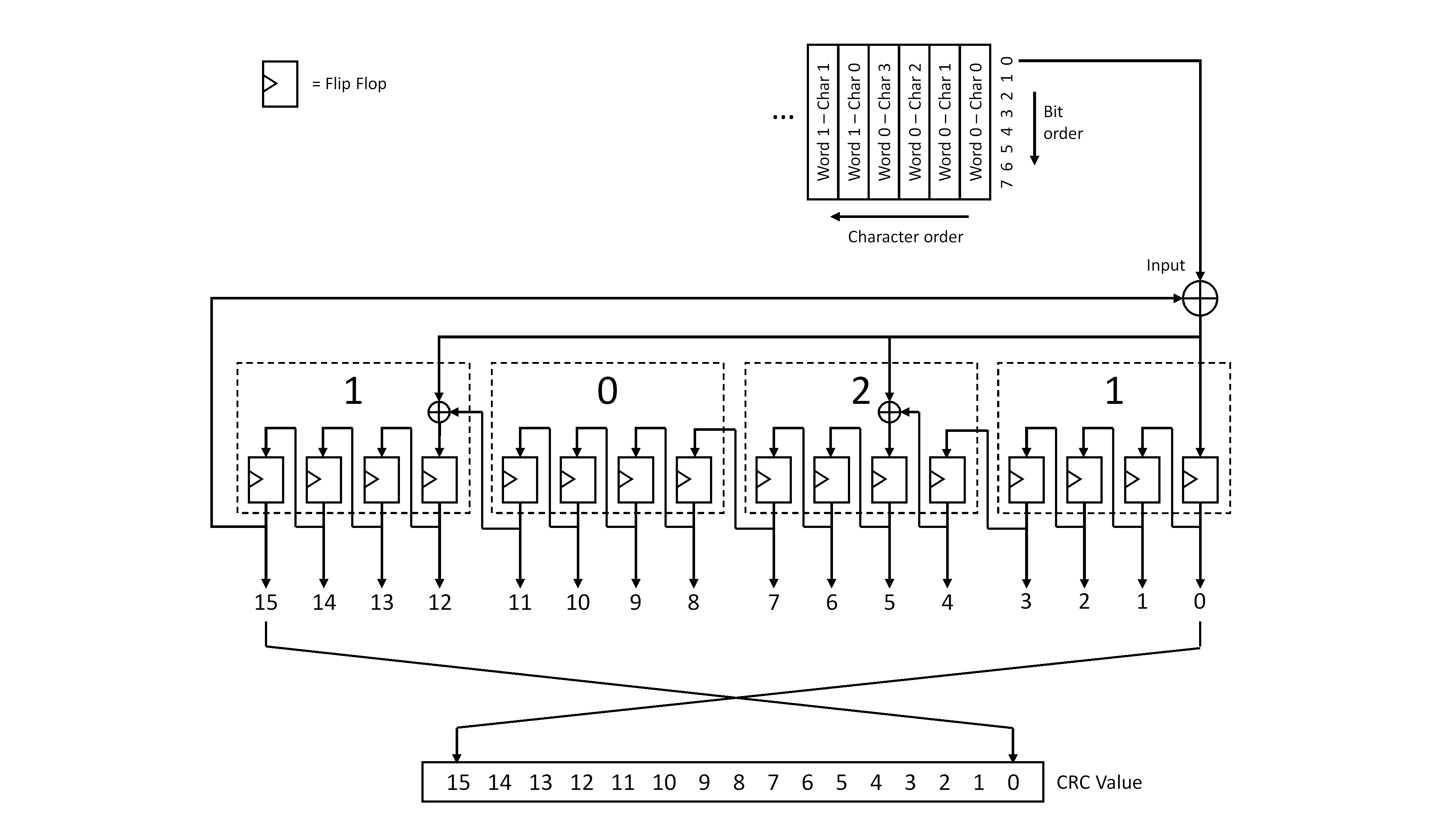 Figure 545: Illustration of bit ordering during 16-bit CRC calculation
CRC for broadcast frame, FCT, ACK, NACK and SIF
An 8-bit CRC checksum shall be applied to broadcast frames, SIFs, FCTs, FULLs, ACKs and NACKs.
The 8-bit CRC shall cover an entire broadcast frame, from and including the comma in the start of broadcast frame control word, up to and including the Sequence Number in the end of broadcast frame control word.
When a control character is included in the CRC calculation, its corresponding data value shall be used.
For example, K28.7 the comma code is replaced by D28.7 in the CRC calculation.
The 8-bit CRC calculation procedures shall:
- use modulo 2 arithmetic for polynomial coefficients.
- use a systematic binary (n+16,n) block code, where (n+8) is the number of bits of the code word
 and n is divisible by 8; n is the number of bits covered by the CRC.
 - use the following generating polynomial:

- use byte format as input and output, for which the bits are represented as:
 where
where  is the most significant bit and
  is the least significant bit.The 8-bit CRC generation procedure shall behave as follows:
 - The procedure accepts an n-bit input which is used to construct
 , where:
- the n-bit input is defined to be the set of bits
 grouped into
  bytes where
  is the byte index and
  is the bit index.
 - the
input bytes correspond to the fields covered by the CRC excluding the CRC byte; the first byte transmitted has index
 ; the last byte transmitted has index
  .
.
- is a polynomial
 having binary coefficients
  .
.
- can be represented as an n-bit vector where coefficient
 of the highest power of
  is the most significant bit and coefficient
  of the lowest power of
is the least significant bit.
of the lowest power of
is the least significant bit. - the bit vector representation of
is formed by concatenating the
bytes of the input in transmission order, where the least significant bit
of each byte is taken first and the most significant bit
of each byte is taken last:


- the n-bit input is defined to be the set of bits
- The procedure generates the remainder polynomial
 given by the equation:
 where
where  and
and  are binary coefficients.* The Header and Data CRC are formed from the 8-bit vector representation of
; the least significant bit
of the CRC byte is coefficient
are binary coefficients.* The Header and Data CRC are formed from the 8-bit vector representation of
; the least significant bit
of the CRC byte is coefficient  of the highest power of
, while the most significant bit
of the CRC byte is coefficient
of the highest power of
, while the most significant bit
of the CRC byte is coefficient  of the lowest power of
:
of the lowest power of
:

- 1 The codeword
 is formed by concatenating the bit vector representations of
and
.
is formed by concatenating the bit vector representations of
and
. - 2 When a Galois version of a Linear Feedback Shift Register is used for CRC generation, its initial value is zero.
The 8-bit CRC seed shall be 0x00.
If the CRC generation procedure is applied to the bytes covered by the CRC excluding the CRC byte, the generated CRC shall be compared directly with the expected CRC byte.
If the generated and expected CRC bytes specified in requirement 5.7.6.5g are equal, no errors shall be detected.
If the generated and expected CRC bytes specified in requirement 5.7.6.5g are different, an error shall be detected.
If the CRC generation procedure is applied to the bytes covered by the CRC including the CRC byte, the output of the CRC generation procedure shall be zero if no errors have been detected and non-zero if an error has been detected. - 1 When the codeword
 is input to the CRC generator then the remainder is the syndrome:
  .
. - 2 The codeword
is the concatenation of the Header or Data bytes covered by the CRC, followed by the CRC byte.
- 3 The example provided in Figure 546 gives a broadcast frame with its CRC value. Each word has D/K codes of 8 bits plus the K flag bit. The K flag bit is not included in the computation of the CRC. The leftmost D/K code is computed first, e.g. comma K28.7. The CRC is computed starting from bit 0. For each data or CRC value the leftmost hexadecimal character contains the most significant bit.
- 4 The ordering of bits for the 8-bit CRC calculation is illustrated in Figure 547.
When an implementation can be simplified, the 8-bit CRC calculation may be carried out in the Multi-Lane or Lane layer.
From the perspective of the implementation, the Multi-Lane and Lane layers are effectively sub-layers forming part of the Data Link layer.
|
0 7
|
8 15
|
16 23
|
24 31
|
|
COMMA
|
SBF
|
0x00
|
0x00
|
|
0x00
|
0x00
|
0x00
|
0x00
|
|
0x01
|
0x01
|
0x01
|
0x01
|
|
EBF
|
0x00
|
0x41
|
0x29
|
|
0 7
|
8 15
|
16 23
|
24 31
|
|
FCT
|
0x01
|
0x01
|
0x4F
|
Figure 546: Examples of CRC calculation for a broadcast frame and FCT
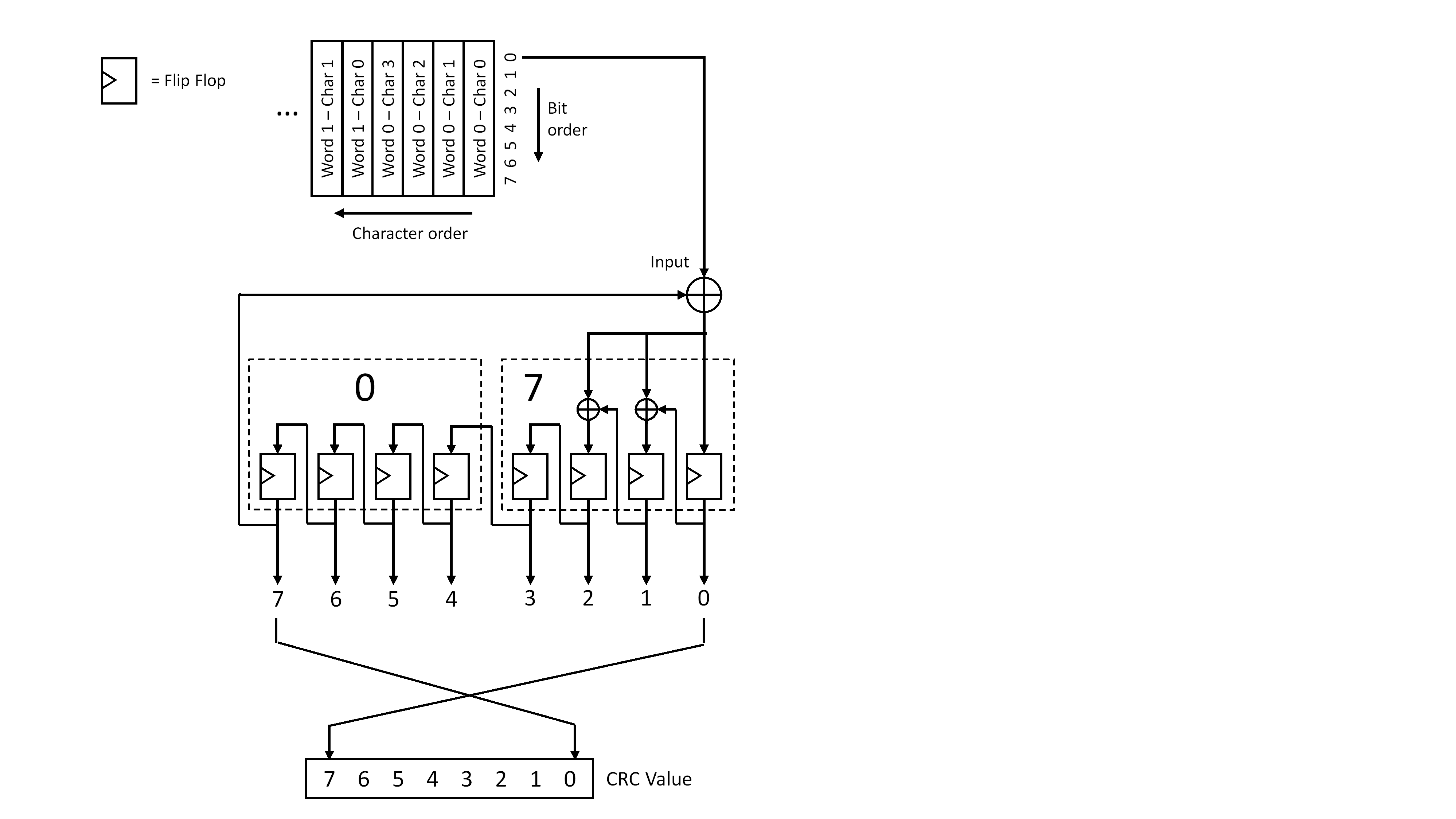 Figure 547: Illustration of bit ordering during 8-bit CRC calculation
Idle frames
Idle frames shall be generated when there are no data frames, FCTs, broadcast frames or FULLs to send.
The Sequence Number field in the start of idle frame shall be set to the current value of the Transmit Sequence Number, including the polarity flag.
After a link reset this counter is set to zero so if an idle frame is the first frame sent after link reset, its Sequence Number field is zero. If a data frame, FCT, or broadcast frame is the first frame sent after a link reset its Sequence Number field is one.
The start of idle frame control word shall be followed by a series of pseudo-random data words which forms a pseudo random bit sequence when transmitted as specified in clause 5.7.6.2.3.
Frame reception
When a complete data frame is received without a CRC error and in the correct sequence, as indicated by its sequence number, the data segment contained in that data frame shall be written into the appropriate input virtual channel buffers, as determined by its virtual channel number.
When a data frame is received with a CRC error or out of sequence, it shall be discarded.
When a complete broadcast frame is received without a CRC error and in the correct sequence, as indicated by its sequence number, the broadcast message contained in that broadcast frame shall be written to the broadcast message interface.
When a broadcast frame is received with a CRC error or out of sequence, it shall be discarded.
When an FCT is received without a CRC error and in the correct sequence, as indicated by its sequence number, the FCT shall be passed to the output flow control mechanism of the virtual channel indicated by the virtual channel number in the FCT.
When an FCT is received with a CRC error or out of sequence, it shall be discarded.
Error recovery
Error recovery buffer
Data segments, FCTs and broadcast messages shall be temporarily placed in an error recovery buffer prior to passing them to the Multi-Lane or Lane layer for sending over the SpaceFibre link, so that they can be resent if an error occurs.
The error recovery buffer shall be able to store at least one FCT regardless of how many data segments and broadcast messages it contains.
The error recovery buffer shall be able to store at least one broadcast message regardless of how many data segments and FCTs it contains.
The total number of frames or FCT words that can be stored in the error recovery buffer after they are sent is less than 128, because of the size of SEQ_NUM.
The data segments, FCTs and broadcast messages in the error recovery buffer shall be referenced by the Sequence Number, SEQ_NUM, given to them when they are sent over the SpaceFibre link.
Sequence numbering is specified in clause 5.7.6.3.
When the contents of the error recovery buffer are resent, the broadcast frames shall always be sent before FCT and data frames, even if the broadcast frames were not sent before the NACK was received.
The frame precedence specified in clause 5.3.10 prevails.
When a small size, limited functionality SpaceFibre interface is needed and the sending and receiving of low latency broadcast messages is not important, the contents of the error recovery buffer may be resent in any order.
When the contents of the error recovery buffers are resent they shall be given new Sequence Numbers following on from the last correctly received Sequence Number at the far-end, as indicated by the SEQ_NUM field received in the NACK control word, plus one and incrementing with each frame/FCT that is retried or otherwise sent.
The data frames, FCTs, and broadcast frames that are resent have the polarity flag in the SEQ_NUM set to the new polarity value of the Transmit Polarity Flag determined in clause 5.7.6.3.1.
On link reset, the error recovery buffer shall be emptied.
On LaneReset, the error recovery buffer shall not be emptied.
The number of error recovery attempts shall be incremented when a RETRY control word is sent.
The number of error recovery attempts shall be recorded and made available in a status register.
The number of error recovery attempts shall be cleared by power-on reset or interface reset, or by command from the Management Information Base.
The size of the error recovery buffer shall be implementation dependent.
- 1 An appropriate size for the error recovery buffer is long enough to hold all the data and control words that can fit on the line for as long as it takes to send them and receive an ACK in reply.
- 2 When multiple lanes are used, proportionally more data can be held on the line.
The error recovery buffer shall be considered as full when there is insufficient space in the buffer to store either an FCT, broadcast frame or all or part of a data frame.
When the error recovery buffer becomes full, or when a total of 127 frames or FCTs are waiting to be acknowledged, no more data segments, FCTs and broadcast messages shall be accepted.
When the error recovery buffer is full, only FULLs, ACKs and NACKs shall be sent by the Data Link layer.
When the error recovery buffer is full, FULL control words shall be sent. - 1 Control word precedence is specified in clause 5.3.10.
- 2 The control word precedence of requirement 5.3.10c means that a broadcast frame is sent before a FULL, when there is no space to store a data frame, but there is space to store a broadcast frame.
When a total of 127 frames or FCTs are pending to be acknowledged FULL words shall be sent.
127 is the maximum number of frames or FCTs that can be outstanding due to the size of the Sequence Number.
When an RXERR or CRC error occurs, a FULL control word should be sent if all of the following conditions occur:
- All output virtual channel buffers are empty.
- There are no data frames, FCTs or broadcast frames to send.
- The error recovery buffer is not empty.
If an ACK control word is not received because of an error, a new ACK will be received only if a new data frame, broadcast frame or FCT is sent. This clause guarantees that in this situation a new ACK is received and the error recovery buffer is emptied.
ACK/NACK control
Sending ACKs
When a data frame, broadcast frame, FCT or FULL is received without a sequence error or CRC error, an ACK shall be requested to be sent.
ACKs shall be sent as soon as possible after being requested, while respecting control word precedence.
- 1 Control word precedence is specified in clause 5.3.10.
- 2 ACKs are not buffered before they are sent.
After an ACK is sent, a minimum of 15 words shall be sent before another ACK is sent.
This ensures that the bandwidth reserved quality of service works independently of the size of data frames.
If another data frame, broadcast frame, FCT or FULL is received while an ACK is pending, only one ACK shall be sent.
An ACK can cover one or more data frames, broadcast frames, FCTs or FULLs.
When an ACK is sent, it shall contain the current value of the Receive Sequence Counter and the Receive Polarity Flag.
When a NACK is requested to be sent, any pending ACK shall be cancelled and not sent.
Sending NACKs
A NACK shall be requested to be sent under any of the following conditions:
- The Data Word Identification state machine is in the RxDataFrame, RxBroadcastFrame, or RxData&BroadcastFrame state and an RXERR control word is received or a CRC error occurs.
- When a sequence error is detected in a control word with a valid CRC.
- 1 The intention is only to send a NACK when an error recovery operation is needed. Therefore, a NACK is not sent when the Data Word Identification state machine is in the RxNothing or RxIdle state, even when an error is detected.
- 2 The Sequence Number of the FULL control word or idle frame ought to have the same sequence number as the last correctly received data frame, FCT, or broadcast frame i.e. be the same as the current value of the Receive Sequence Counter. If this is not the case, a sequence error has occurred indicating that a frame that has been sent has not been received. A NACK is then sent to indicate to the far-end the last correctly received data frame, FCT or broadcast frame.
- 3 When an idle frame is received that has the correct Sequence Number there is no need to send an ACK. The correct Sequence Number indicates that the last data frame, FCT or broadcast frame has been received correctly. If the ACK sent for this frame has gone missing, it does not matter unless the frame error recovery buffer fills up which does not happen unless more data frames, FCTs or broadcast frames are sent. In which case other ACKs are sent.
A NACK shall not be requested to be sent if an unrecognized control word is received.
This is to permit forward compatibility with future versions of the SpaceFibre standard.
A NACK requested to be sent shall be sent as soon as possible, while respecting control word precedence.
- 1 A NACK that is requested to be sent which cannot be sent immediately means that a NACK is pending to be sent. The pending NACK is sent as soon as possible.
- 2 See clause 5.3.9 for the specification of precedence.
When a NACK is sent, it shall use the current value of the Receive Sequence Counter with the Receive Polarity Flag determined by the Receive Error state machine.
See clause 5.7.7.3 which specifies the value of the Receive Polarity Flag.
When an ACK is requested to be sent, any pending NACK shall be cancelled and not sent.
Receiving ACKs
When an ACK is received it shall be checked for errors using its CRC.
An ACK shall be considered valid when it has a valid CRC and the polarity flag of its Sequence Number has the same value as the Transmit Polarity Flag.
When a valid ACK is received, all data frames, broadcast frames, and FCTs sent with a Sequence Count less than or equal to the Sequence Count in the ACK shall be deleted from the error recovery buffer, including counter roll over effects using modulo 128 arithmetic.
When a valid ACK is received with a Sequence Count that is different to the Sequence Count of the previous valid ACK or NACK received, and there is no data frame, FCT or broadcast frame in the error recovery buffer with the Sequence Count of the ACK, the SpaceFibre link shall be reset and the Link Reset Caused by Protocol Error status parameter asserted.
Receiving NACKs
When a NACK is received it shall be checked for errors using its CRC.
A NACK shall be considered valid when it has a valid CRC and the polarity flag of its Sequence Number has the same value as the Transmit Polarity Flag.
When a valid NACK is received the following actions shall be executed in the specified order:
- Delete all data frames, FCTs and broadcast frames, sent with a Sequence Count less than or equal to the Sequence Count in the NACK, from the frame error recovery buffer, including counter roll over effects using modulo 128 arithmetic.
- Set the Transmit Sequence Counter to the value of the NACK sequence Count.
- Send a RETRY word before the contents of the error recovery buffer are sent.
- Invert the polarity flag of the Transmit Sequence Number.
- Follow the precedence indicated in clause 5.3.10 when resending data frames, FCTs and broadcast messages.
- Resend the data frames, FCTs or broadcast frames left in the error recovery buffer since the NACK has signalled that they have not been received correctly.
- Give new sequence numbers to the data frames, broadcast frames and FCTs, when they are resent.
- 1 The data frames, FCTs or broadcast frames left in the error recovery buffer are those which have a Sequence Count greater than that of the NACK.
- 2 See clause 5.7.7.2.2 for reasons why a NACK is transmitted.
A NACK received with the polarity flag in the Sequence Number, SEQ_NUM, which is different to the Transmit Polarity Flag shall be ignored and not cause error recovery.
This prevents an error from causing multiple error recovery attempts.
When a valid NACK is received with a Sequence Count that is different to the Sequence Count of the previous valid ACK or NACK received, and there is no data frame, FCT or broadcast frame in the error recovery buffer with the Sequence Count of the NACK, the SpaceFibre link shall be reset and the Link Reset Caused by Protocol Error status parameter asserted.
Receive Error state machine
General
The Receive Error state machine shall be used to determine the state of the Receive Polarity Flag field of the Receive Sequence Number.
The state diagram for the Receive Error state machine is illustrated in Figure 548
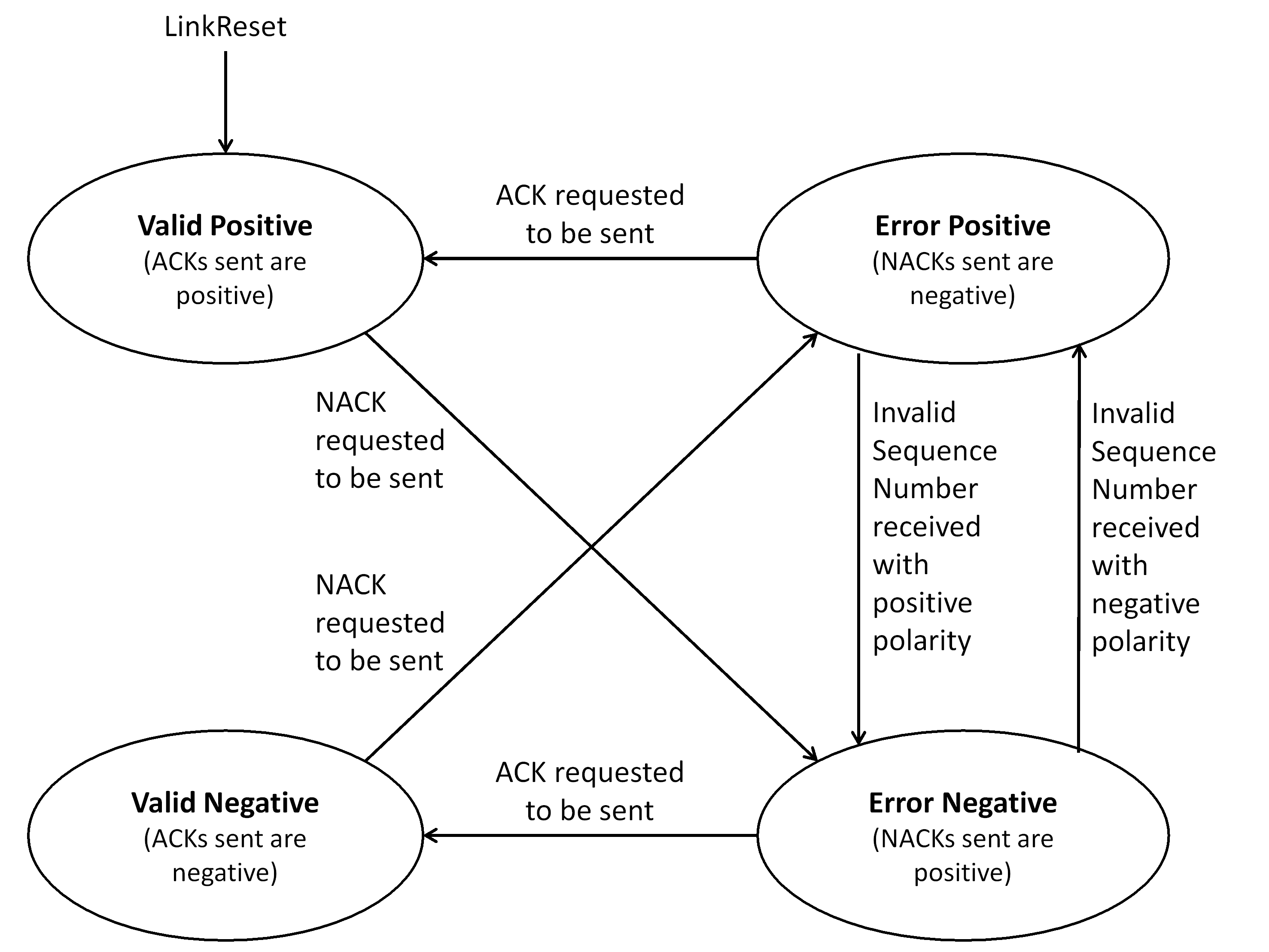 Figure 548: Receive Error state machine
Valid Positive State
The Valid Positive state shall be entered on the following conditions:
- LinkReset command.
- From the Error Positive state, when an ACK is requested to be sent. When in the Valid Positive state, the Receive Polarity Flag shall be positive.
ACKs are therefore sent with a positive Sequence Number.
The Receive Error state machine shall leave the Valid Positive state on the following conditions:
- When a NACK is requested to be sent, move to the Error Negative state, before sending the NACK.
Note the NACK is therefore sent with a positive Sequence Number, because NACKs are sent with the opposite polarity of that indicated by the Receive Error state machine.
Valid Negative State
The Valid Negative state shall be entered on the following conditions:
- From the Error Negative state, when an ACK is requested to be sent. When in the Valid Negative state, the Receive Polarity Flag shall be negative.
ACKs are therefore sent with a negative Sequence Number.
The Receive Error state machine shall leave the Valid Negative state on the following conditions:
- When a NACK is requested to be sent, move to the Error Positive state, before sending the NACK.
Note the NACK is therefore sent with a negative Sequence Number.
Error Positive State
The Error Positive state shall be entered on the following conditions:
- From the Valid Negative state, when a NACK is requested to be sent.
- From Error Negative state, when an invalid Sequence Number is received with negative polarity. When in the Error Positive state, the Receive Polarity Flag shall be positive.
NACKs are therefore sent with negative Sequence Numbers as NACKs are sent with the opposite polarity to that indicated by the Receive Error state machine.
The Receive Error state machine shall leave the Error Positive state on the following conditions:
- When an ACK is requested to be sent, move to the Valid Positive state, before sending the ACK.
- When a data frame, broadcast frame, FCT, SIF or FULL is received containing a positive Sequence Number but an incorrect, out of sequence, Sequence Count, move to the Error Negative state, before sending any NACK in response to this error.
Note the ACK is therefore sent with a positive Sequence Number.
Error Negative State
The Error Negative state shall be entered on the following conditions:
- From the Valid Positive state, when a NACK is requested to be sent.
- From Error Positive state, when an invalid Sequence Number is received with positive polarity. When in the Error Negative state, the Receive Polarity Flag shall be negative.
NACKs are therefore sent with positive Sequence Numbers.
The Receive Error state machine shall leave the Error Negative state on the following conditions:
- When an ACK is requested to be sent, move to the Valid Negative state, before sending the ACK.
- When a data frame, broadcast frame, FCT, SIF or FULL is received containing a negative Sequence Number but an incorrect, out of sequence, Sequence Count, move to the Error Positive state, before sending any NACK in response to this error.
Note the ACK is therefore sent with a negative Sequence Number.
Data word identification state machine
General
The Data Word Identification state machine shall be used to identify which type of frame a data word belongs to, in order to support de-multiplexing of different frame types.
The state diagram for the Data Word Identification state machine is illustrated in Figure 549.
Unknown control words shall not cause an error when received.
Unknown control words are ignored which ensures forwards compatibility with future developments of SpaceFibre.
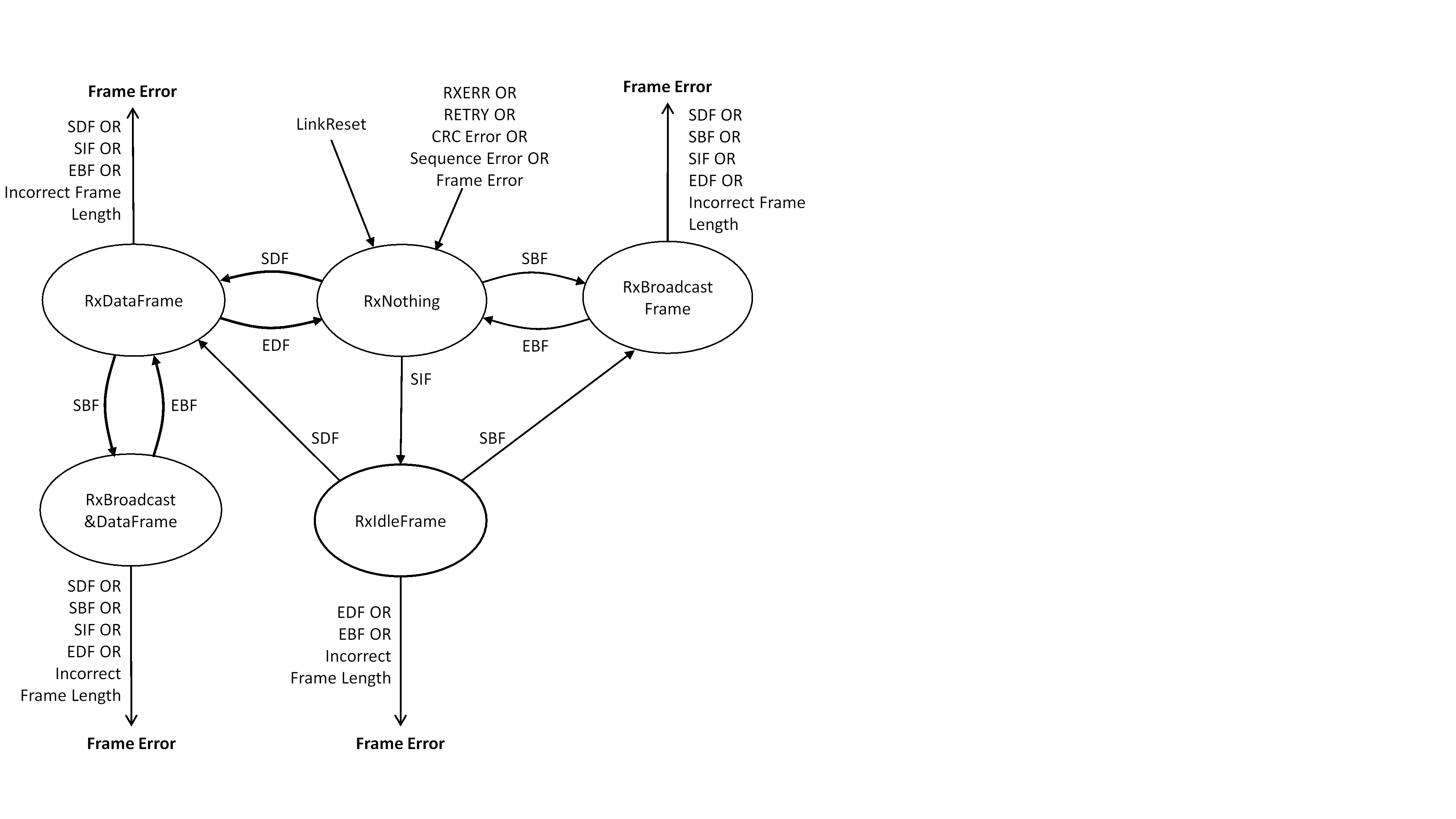 Figure 549: Data Word Identification state machine
RxNothing state
The RxNothing state shall be entered on one of the following conditions:
- Following a link reset.
- From the RxDataFrame state, when an EDF is received.
- From the RxBroadcastFrame state, when an EBF is received.
- From any state when an RXERR, a RETRY, a sequence error, a CRC error or an unexpected control word or incorrect frame length is received.
- 1 A sequence error occurs when the Sequence Count in a SEQ_NUM of a data frame, FCT or broadcast frame is not one more, using modulo 128 arithmetic, than the value in the Receive Sequence Counter or the polarity flag is different to the Receive Polarity flag. It also occurs when the Sequence Number of an idle frame or a FULL word does not match the value of the Receive Sequence Number.
- 2 Unexpected control words are valid control words at an unexpected time. Therefore, unexpected control words are handled differently to unknown control words.
When in the RxNothing state the Data Word Identification state machine shall initiate the following actions: - Indicate that no frame data is being received.
- Discard any EBF and EDF that are received. The Data Word Identification state machine shall leave the RxNothing State on one of the following conditions:
- When an SBF is received, move to the RxBroadcastFrame state.
- When an SDF is received, move to the RxDataFrame state.
- When an SIF is received, move to the RxIdleFrame state.
No action is taken in the RxNothing state when an EDF or EBF is received.
RxDataFrame state
The RxDataFrame state shall be entered on one of the following conditions:
- From the RxNothing state, when an SDF is received.
- From the RxIdleFrame state, when an SDF is received.
- From the RxBroadcast&DataFrame state, when an EBF is received. When in the RxDataFrame state the Data Word Identification state machine shall initiate the following actions:
- Indicate that data words being received belong to a data frame.
- Count the number of data words being received in the data frame. The Data Word Identification state machine shall leave the RxDataFrame state on one of the following conditions, which are evaluated in the order given:
- When a RETRY is received, move to the RxNothing state.
- When an RXERR is received, move to the RxNothing state.
- When a CRC error is detected, move to the RxNothing state.
- When a sequence error is detected, move to the RxNothing state.
- When an SBF is received move to the RxBroadcast&DataFrame state.
- When an EDF is received, move to the RxNothing state.
- When one or more of the following conditions occurs, flag a Frame Error and move to the RxNothing state:
- an SDF is received.
- an SIF is received.
- an EBF is received.
- the data word counter exceeds the maximum permitted amount of data in a data frame.
The maximum permitted amount of data in a data frame is L×64, where L is the value of "maximum number of data-sending lanes" parameter.
RxBroadcastFrame state
The RxBroadcastFrame state shall be entered on one of the following conditions:
- From the RxNothing state, when an SBF is received.
- From the RxIdleFrame state, when an SBF is received. When in the RxBroadcastFrame state the Data Word Identification state machine shall initiate the following actions:
- Indicate that data words being received belong to a broadcast frame.
- Count the number of data words being received in the broadcast frame. The Data Word Identification state machine shall leave the RxBroadcastFrame state on one of the following conditions, which are evaluated in the order given:
- When a RETRY is received, move to the RxNothing state.
- When an RXERR is received, move to the RxNothing state.
- When a CRC error is detected, move to the RxNothing state.
- When a sequence error is detected, move to the RxNothing state.
- When an EBF is received and the broadcast word counter is equal to the permitted number of data words in a broadcast frame, move to the RxNothing state.
- When one or more of the following conditions occurs, flag a Frame Error and move to the RxNothing state:
- an SDF is received.
- an SBF is received.
- an SIF is received.
- an EDF is received.
- an EBF is received and the broadcast word counter is not equal to the permitted number of data words in a broadcast frame.
- the broadcast word counter exceeds the permitted number of data words in a broadcast frame.
RxBroadcast&DataFrame state
The RxBroadcast&DataFrame state shall be entered on the following condition:
- From the RxDataFrame state, when an SBF is received. When in the RxBroadcast&DataFrame state the Data Word Identification state machine shall initiate the following actions:
- Indicate that data words being received belong to a broadcast frame.
- Count the number of data words being received in the broadcast frame. The Data Word Identification state machine shall leave the RxBroadcast&DataFrame state on one of the following conditions, which are evaluated in the order given:
- When a RETRY is received, move to the RxNothing state.
- When an RXERR is received, move to the RxNothing state.
- When a CRC error is detected, move to the RxNothing state.
- When a sequence error is detected, move to the RxNothing state.
- When an EBF is received and the broadcast word counter is equal to the permitted number of data words in a broadcast frame, move to the RxDataFrame state.
- When one or more of the following conditions occurs, flag a Frame Error and move to the RxNothing state:
- an SDF is received.
- an SBF is received.
- an SIF is received.
- an EDF is received.
- an EBF is received and the broadcast word counter is not equal to the permitted number of data words in a broadcast frame.
- the broadcast word counter exceeds the permitted number of data words in a broadcast frame.
RxIdleFrame state
The RxIdleFrame state shall be entered on one of the following conditions:
- From the RxNothing state, when an SIF is received. When in the RxIdleFrame state the Data Word Identification state machine shall initiate the following actions:
- Indicate that data words being received belong to an idle frame.
- Count the number of data words being received. The Data Word Identification state machine shall leave the RxIdleFrame state on one of the following conditions, which are evaluated in the order given:
- When a RETRY is received, move to the RxNothing state.
- When an RXERR is received, move to the RxNothing state.
- When a CRC error is detected, move to the RxNothing state.
- When a sequence error is detected, move to the RxNothing state.
- When an SBF is received, move to the RxBroadcastFrame state.
- When an SDF is received, move to the RxDataFrame state.
- When one or more of the following conditions occurs, flag a Frame Error and move to the RxNothing state:
- an EDF is received.
- an EBF is received.
- the data word counter exceeds the maximum permitted amount of data in an idle frame.
When an SIF is received, the Data Word Identification state machine remains in the RxIdleFrame state.
Control Words
FCT, ACK, NACK, FULL and RETRY control words shall be able to be received in any state.
Unknown control words shall be ignored and no action taken when they are received.
This is to maintain compatibility with future developments of the SpaceFibre standard.
Link Reset state machine
General
The Link Reset state machine shall be used to ensure that both ends of a link are reset, when one or other end of that link is reset.
The state diagram for the Link Reset state machine is illustrated in Figure 550.
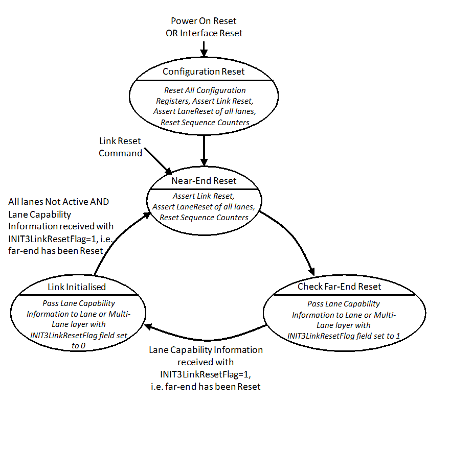 Figure 550: Link Reset state machine
Configuration Reset state
The Configuration Reset state shall be entered on one of the following conditions:
- When Power On Reset is asserted.
- When the Interface Reset management parameter is set. When in the Configuration Reset state the Link Reset state machine shall initiate the following action:
- Reset all the configuration parameters.
- Assert Link Reset.
- Assert LaneReset of all lanes.
The sequence counters and related logic are reset when Link Reset is asserted, see requirement 5.3.5.1.2c for example.
The Link Reset state machine shall leave the Configuration Reset state unconditionally and move to the Near-End Reset state.
Near-End Reset state
The Near-End Reset state shall be entered on one of the following conditions:
- Unconditionally from the Configuration Reset state.
- When the Link Reset management parameter is set.
- From the Link Initialised state, when all lanes are NOT Active and Lane Capability information is received from the Lane or Multi-Lane layer, with the INIT3LinkResetFlag field set to 1, indicating that the far-end has been reset. When in the Near-End Reset state, the Link Reset state machine shall initiate the following actions:
- Assert Link Reset.
- Assert LaneReset of all lanes.
- Reset the sequence counters and related logic. The Link Reset state machine shall leave the Near-End Reset state on one of the following conditions, which are evaluated in the order given:
- When Power On Reset is asserted, move to the Configuration Reset state.
- When the Interface Reset management parameter is set, move to the Configuration Reset state.
- Unconditionally, move to the Check Far-End Reset state.
Check Far-End Reset state
The Check Far-End Reset state shall be entered on the following condition:
- Unconditionally from the Near-End Reset state. When in the Check Far-End Reset state the Link Reset state machine shall initiate the following actions:
- Pass Lane Capability information to the Lane layer or Multi-Lane layer with the INIT3LinkResetFlag field set to 1. The Link Reset state machine shall leave the Check Far-End Reset state on one of the following conditions, which are evaluated in the order given:
- When Power On Reset is asserted, move to the Configuration Reset state.
- When the Interface Reset management parameter is set, move to the Configuration Reset state.
- When the Link Reset management parameter is set, move to the Near-End Reset state.
- When Lane Capability information is received from the Lane or Multi-Lane layer with the INIT3LinkResetFlag field set to 1, indicating that the far-end has been reset, move to the Link Initialised state.
Link Initialised state
The Link Initialised state shall be entered on the following condition:
- From the Check Far-End Reset state, when Lane Capability information is received from the Lane or Multi-Lane layer with the INIT3LinkResetFlag field set to 1, indicating that the far-end has been reset. When in the Link Initialised state, the Link Reset state machine shall initiate the following actions:
- Pass near-end Lane Capability information to the Lane layer or Multi-Lane layer with the INIT3LinkResetFlag field set to 0. The Link Reset state machine shall leave the Link Initialised state on one of the following conditions, which are evaluated in the order given:
- When Power On Reset is asserted, move to the Configuration Reset state.
- When the Interface Reset management parameter is set, move to the Configuration Reset state.
- When the Link Reset management parameter is set, move to the Near-End Reset state.
- When all lanes are NOT active and Lane Capability information is received from the Lane or Multi-Lane layer with the INIT3LinkResetFlag field set to 1, indicating that the far-end has been reset, move to the Near-End Reset state.
Link reset
When link reset is asserted the following actions shall take place, for all virtual channels operating over the link:
- All packets being written to output virtual channels of the link stop being written to the output virtual channel.
- The data inside the output virtual channel buffers are flushed.
- The remainder of the packets not yet written to the output virtual channels are discarded.
- All packets being read from input virtual channels of the link stop being read from the input virtual channels.
- The data inside the input virtual channel buffer is flushed.
- The part of the packet that has already been read from each virtual channel of the link is terminated with an EEP, indicating that the rest of the packet was not received.
- If the last character read out of the input virtual channel by the user when the link became inoperative was an EOP, EEP or Fill, an EEP is not added to that packet. When link reset is asserted, the following actions shall take place:
- Stop passing the current data frame or broadcast frame to the Lane or Multi-Lane layer.
- Set the Broadcast Bandwidth Credit Counter to zero as per requirement 5.7.5d.
- Set the initial seed for the PRBS generator to 0xFFFF and use this value to calculate the first idle word after link reset as per requirements 5.7.6.2.3d and 5.7.6.2.3e.
- Clear the Transmit Sequence Counter to zero as per requirement 5.7.6.3.1d.
- Clear the Transmit Polarity Flag to zero as per requirement 5.7.6.3.1e.
- Clear the Receive Sequence Counter to zero as per requirement 5.7.6.3.2e.
- Clear the Receive Polarity Flag to zero as per requirement 5.7.6.3.2f.
- Empty the error recovery buffer as per requirement 5.7.7.1h.
- Move the Data Word Identification state machine to the RxNothing state as per requirement 5.7.8.2a.1.
- Move the Link Reset state machine to the Near-End Reset state as per requirement 5.7.9.3a.2.
Network layer
Network layer responsibilities
The SpaceFibre network layer shall transfer SpaceFibre packets, and broadcast messages over a SpaceFibre network.
The interfaces to and from the Network layer are illustrated in Figure 551.
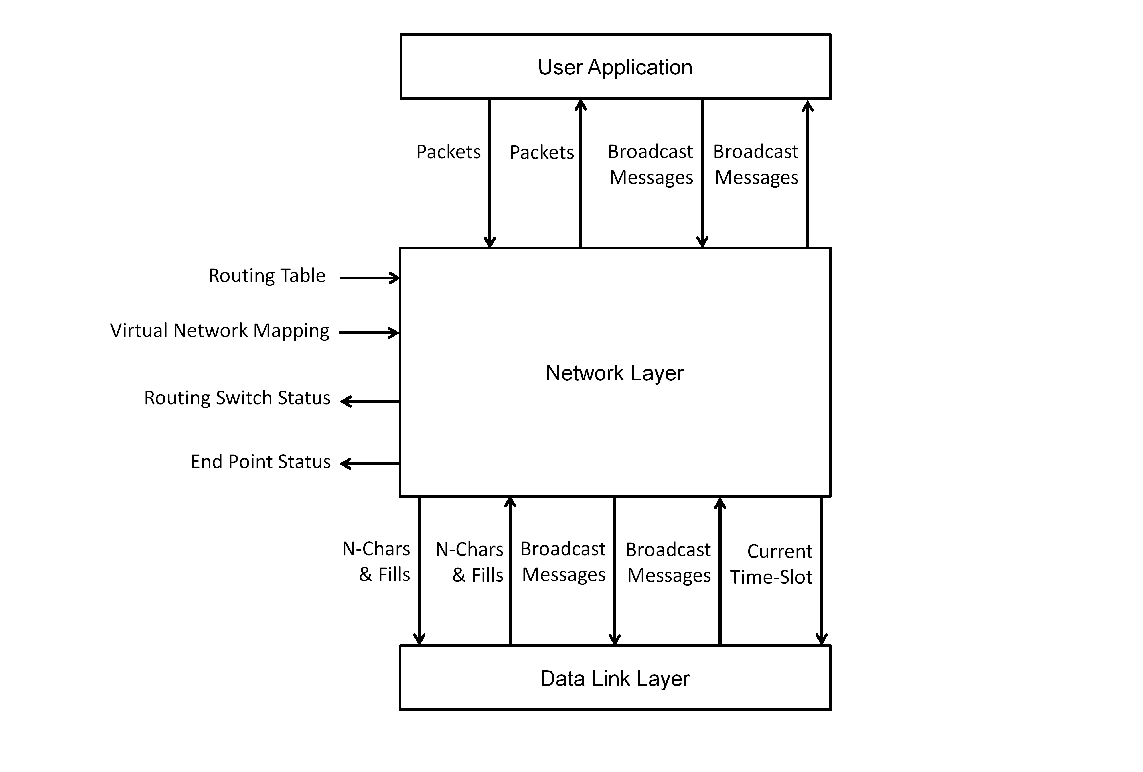 Figure 551: Interfaces to the Network layer
The Network layer shall receive Packets and Broadcast Messages from the User Application, for sending over the SpaceFibre network.
The Network layer shall pass Packets and Broadcast Messages that have been received over the SpaceFibre network, to the User Application layer.
The Network layer shall pass N-Chars and Fills to the Data Link layer for sending over a virtual channel of a link in the network.
The Network layer shall receive N-Chars and Fills from the Data Link layer that have been received through a virtual channel of a link in the network.
The Network layer shall pass Broadcast Messages for sending over the SpaceFibre network to the Data Link layer.
The Network layer shall receive Broadcast Messages that have travelled over the SpaceFibre network from the Data Link layer.
The Network layer shall pass the current time-slot to the Data Link layer.
The Network layer shall be controlled by the following management parameters from the Management Information Base:
- Routing switch virtual network to virtual channel mapping.
- Routing switch routing table. The Network layer shall provide the following status information to the Management Information Base:
- Routing switch status.
- End-point status.
SpaceFibre network
Components of a SpaceFibre network
A SpaceFibre network shall comprise one or more nodes and zero or more routing switches interconnected with SpaceFibre links.
The UML diagram in Figure 552 illustrates the components of a SpaceFibre network.
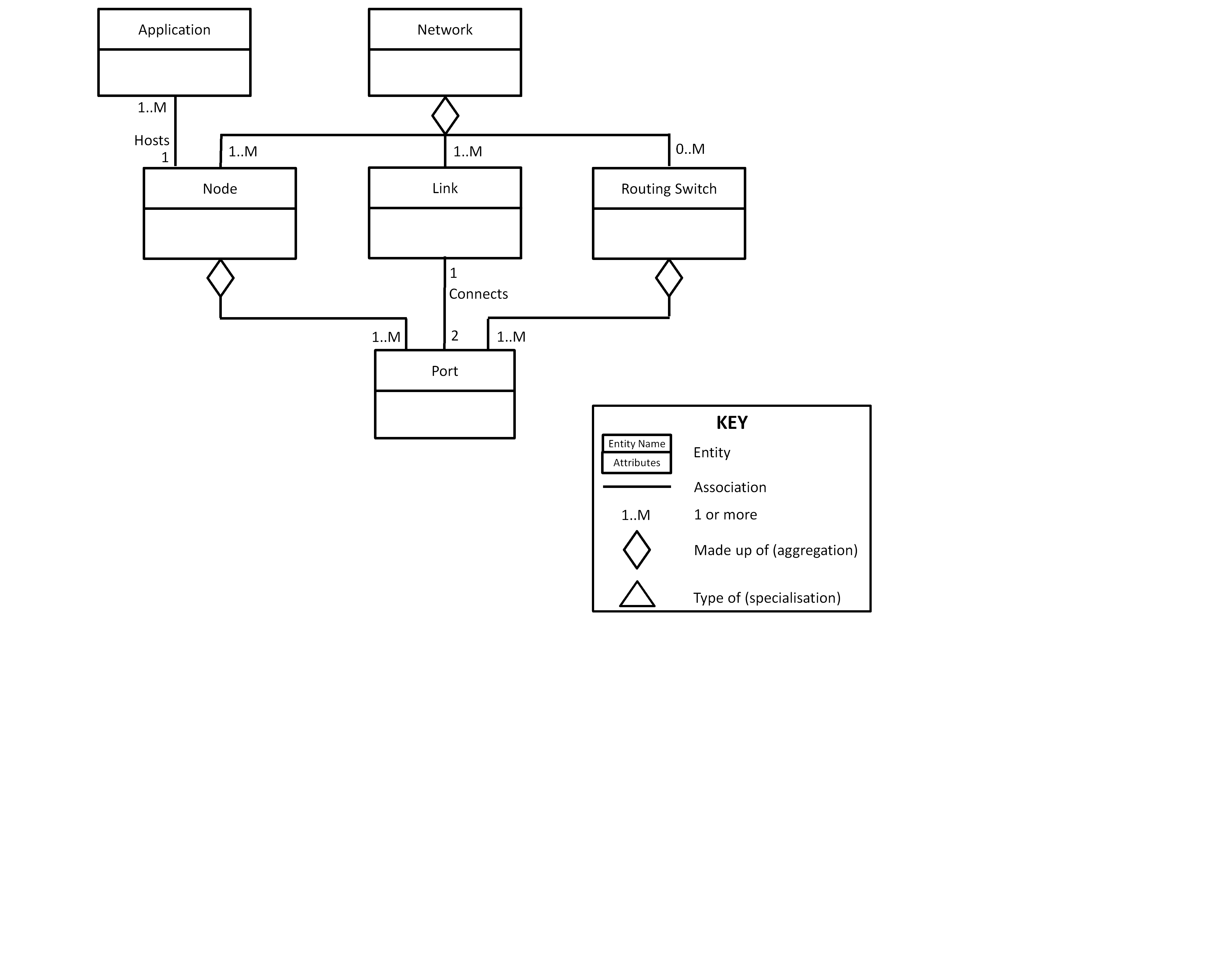 Figure 552: Components of a SpaceFibre network
The SpaceFibre ports of nodes and SpaceFibre routing switches shall be interconnected with links.
Links
A link shall connect two ports together, on the same or different SpaceFibre devices.
Nodes
Nodes shall host the applications using the services of a SpaceFibre network.
Nodes shall transfer packets and broadcast messages from one or more applications over one or more SpaceFibre ports.
End-points and Broadcast Interfaces shall provide the interface between the user application and the SpaceFibre network.
Routing Switch
A routing switch shall be used to interconnect many nodes together so that they can communicate, one with another, without having to have a dedicated point to point link from each node to every other node that it wishes to communicate with.
A SpaceFibre routing switch shall transfer packets from the input port of the switch where the packet arrives, to one or more output ports determined by an address carried at the front of the packet, together with the routing table.
Network
A SpaceFibre network shall transfer packets from source nodes to destination nodes.
Packets from a source node shall travel across a SpaceFibre link to a routing switch or a destination node.
Packets from a routing switch shall travel across SpaceFibre links to other routing switches or to destination nodes.
A SpaceFibre network shall support the broadcast of broadcast messages across the network.
Virtual networks
One or more virtual networks shall run over a SpaceFibre network.
The relationships of a virtual network are illustrated in Figure 553.
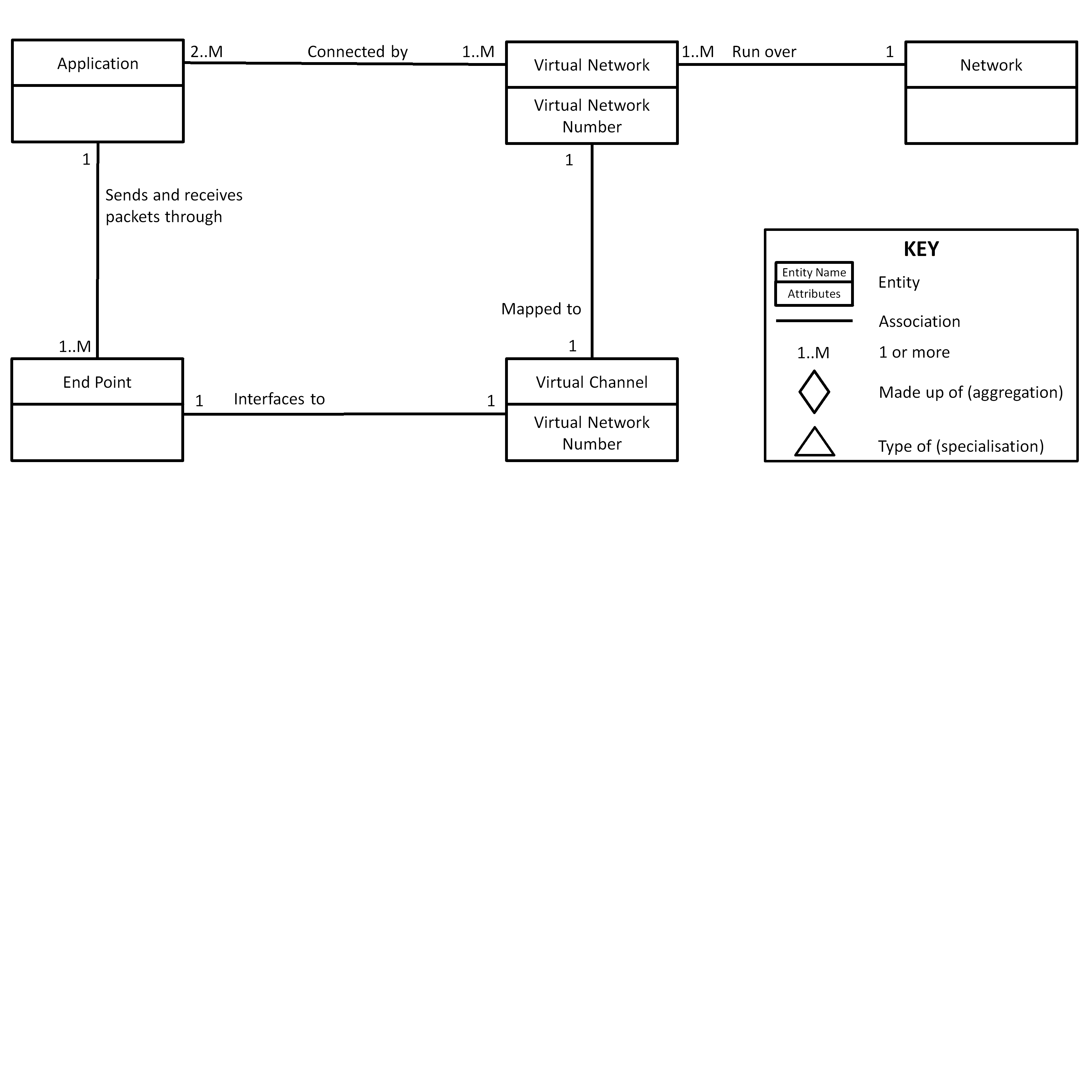 Figure 553: Relationships of a SpaceFibre virtual network
Two or more applications shall be interconnected and communicate via a virtual network.
It shall be possible to connect an application to one or more virtual networks.
An application shall send packets to and receive packets from any other application, that it is interconnected to, via a virtual network.
Packets shall travel within a single virtual network.
Packets shall be sent from an application through an end-point and across a virtual network.
Packets shall be received by an application over a virtual network through an end-point.
Each end-point shall provide an interface to one virtual channel.
A virtual channel shall be configured to belong to a virtual network, by giving it a virtual network number.
The virtual network number maps the virtual channel to a virtual network.
A virtual network shall support the transfer of packets from one end-point on that virtual network to any other end-point on that virtual network.
Each virtual network shall have an identifier from VN0 to VN63.
Virtual network identifiers VN64-VN255 are reserved and shall not be used.
Packets sent over a virtual network shall travel over only that virtual network from source end-point to destination end-point.
Packets are not permitted to travel over different virtual networks from source end-point to destination end-point.
Each virtual network shall operate independently from the other virtual networks.
Each virtual network behaves like a separate SpaceWire network.
In a virtual network, N-Chars from one packet shall not be interleaved with N-Chars from another packet.
The N-Chars in packets flowing over different virtual networks are interleaved at the data link level to provide appropriate QoS for each virtual network.
A virtual network shall use some or all of the links in a SpaceFibre network.
A virtual network shall comprise one virtual channel on each of the links it uses in a SpaceFibre network.
The virtual channels on the links used by the virtual network are each a part of the virtual network.
A virtual network shall use one and only one virtual channel in each of the links used by the virtual network.
A virtual network shall be mapped to one virtual channel on each output port of a node or a routing switch, connected to a link that the virtual network uses.
For example, virtual network VN1 can be mapped to VC3 of port 1 of a routing switch, to VC3 of port 2 and to VC 2 of port 4, and not mapped to any of the other ports.
A virtual network shall only send packets over the virtual channels on the links that are part of the virtual network.
Continuing with the previous example, virtual network VN1 can send packets through port 1, 2 and 4 but not port 3.
A virtual network shall not send packets over virtual channels that are not part of the virtual network.
A virtual network shall not send packets over links that are not part of the virtual network.
A virtual network shall be permitted to be mapped to different virtual channels on different SpaceFibre links used by the virtual network.
For example, virtual network VN1 can be mapped to VC3 of one link and VC6 of another link. In a routing switch each output port has a virtual network to virtual channel mapping. A packet arriving on a specific virtual network of an input port can be switched to any of the output ports that have a mapping to that virtual network (see clause 5.8.8.3). For example, a routing switch configured with VN1 mapped to VC1 on port 2, VN1 mapped to VC4 on port 3 and VN1 mapped to VC 2 on port 4, is able to route a packet arriving on VN1 on port 2 to port 3 (VC4) and port 4 (VC2).
The QoS of a virtual channel on a particular link in a network shall define the QoS of the corresponding virtual network at that point in the network.
It shall be possible for the QoS of a virtual channel, used by a virtual network on one link, to be different to that of other virtual channels on other links used by that same virtual network.
Virtual network VN0 shall be used for sending network control, configuration and housekeeping information to and from SpaceFibre nodes and routing switches.
When a node has a limited number of virtual channels available, virtual network VN0 may be used for control, configuration and housekeeping information for other equipment attached to that node.
Virtual network VN0 shall be mapped to virtual channel VC0.
Virtual network VN0 is not permitted to be mapped to any other virtual channel.
Links
A link shall connect two ports of the same type together.
A link shall comprise one or more lanes.
A link shall contain two or more virtual channels.
When a link is being used in a simple point to point link application or is being used for configuration, control and monitoring purposes only, it may contain one virtual channel.
A virtual channel shall have the same virtual channel number at each end of the link.
A virtual channel has the quality of service defined by the Data Link layer management parameters.
Packet format
A SpaceFibre packet shall comprise one or more data characters followed by an end of packet marker, EOP, or error end of packet marker, EEP.
The format of a SpaceFibre packet is illustrated in Figure 554. It is identical to the format of a SpaceWire packet.
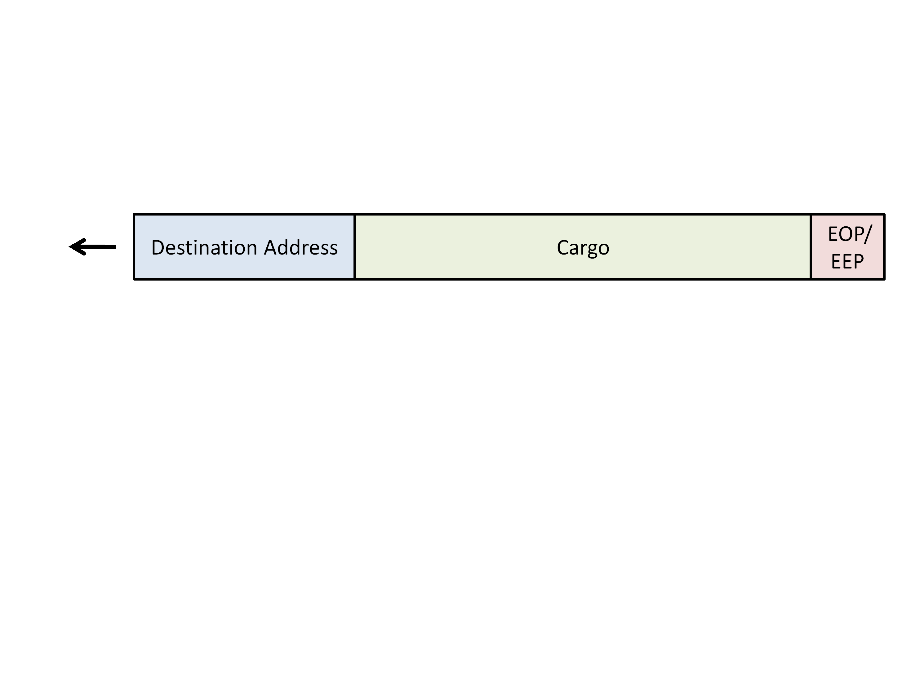 Figure 554: SpaceFibre packet format
The start of a packet shall be either:
- The first data character placed in a virtual channel after a link is reset.
- The data character that immediately follows an EOP or EEP on a virtual channel.
The data character that immediately follows an EOP or EEP is the first data character after the end of the previous packet.
The end of a packet shall be indicated by an EOP or EEP.
The packet shall contain one or more data characters.
A packet may contain zero data characters.
This can happen, for example, if the header is deleted from a packet containing just one data character. In this case, the zero length packet is discarded by the first routing switch that it encounters.
Zero or more data characters at the front of a packet shall form a destination address.
The remaining data characters, following the destination address and up to the EOP or EEP, shall form the cargo.
Sending a packet
To send a SpaceFibre packet over a virtual network, the network layer shall write the N-Chars forming the SpaceFibre packet to an end-point on that virtual network, starting with the leading N-Chars of the SpaceFibre packet.
If the end-point on the virtual network becomes temporarily unable to accept more N-Chars, the network layer shall wait until the end-point is able to accept more N-Chars.
After one SpaceFibre packet has been written to the end-point on a virtual network, the next SpaceFibre packet to be sent over that virtual network shall start to be written, provided that the end-point is able to accept more N-Chars.
Receiving a packet
When N-Chars are received at an end-point on a virtual network, the network layer shall be informed that there is data available to read from that end-point.
The network layer shall read data from an end-point at any time, provided that there is data available at that end-point.
When Link Reset is asserted and the last character read from an end-point was not an EOP, EEP or Fill character, an EEP shall be the next character read from that end-point.
This is equivalent to SpaceWire error handling, which uses the EEP to indicate at the receiver side that the link was disconnected and that the last packet provided was incomplete and in error.
Routing switch
Routing switch
A SpaceFibre routing switch shall forward a packet, arriving at one port, towards its needed destination, through another port or, when self-addressing is enabled, back through the same port as determined by the first data character of the packet and the contents of the routing table.
A packet can be forwarded through two or more ports when packet multicast is being used, see clause 5.8.11.
A SpaceFibre routing switch shall always forward a packet over the same virtual network as that on which the packet arrived at the routing switch.
A SpaceFibre routing switch shall comprise:
- Three to 32 ports, which include SpaceFibre ports that interface to the SpaceFibre network and parallel ports that provide a parallel interface into the routing switch.
- A switch matrix, which connects virtual channels in input ports to virtual channels in output ports.
- A routing table, which together with the leading byte of a packet, the destination address, determines the port a packet is forwarded through.
- A configuration node, which is accessible through the routing switch using port address 0 and which is used to configure the routing switch including the routing table and parameters for each SpaceFibre port.
- One broadcast mechanism, which validates and broadcasts broadcast messages.
- 1 To item 1: The minimum of three ports covers two ports plus a configuration port. A parallel port is the means by which parallel interfaces of various forms can be connected into the router, including large FIFO interfaces, DMA and parallel buses.
- 2 The UML diagram in Figure 555 illustrates the components of a SpaceFibre routing switch.
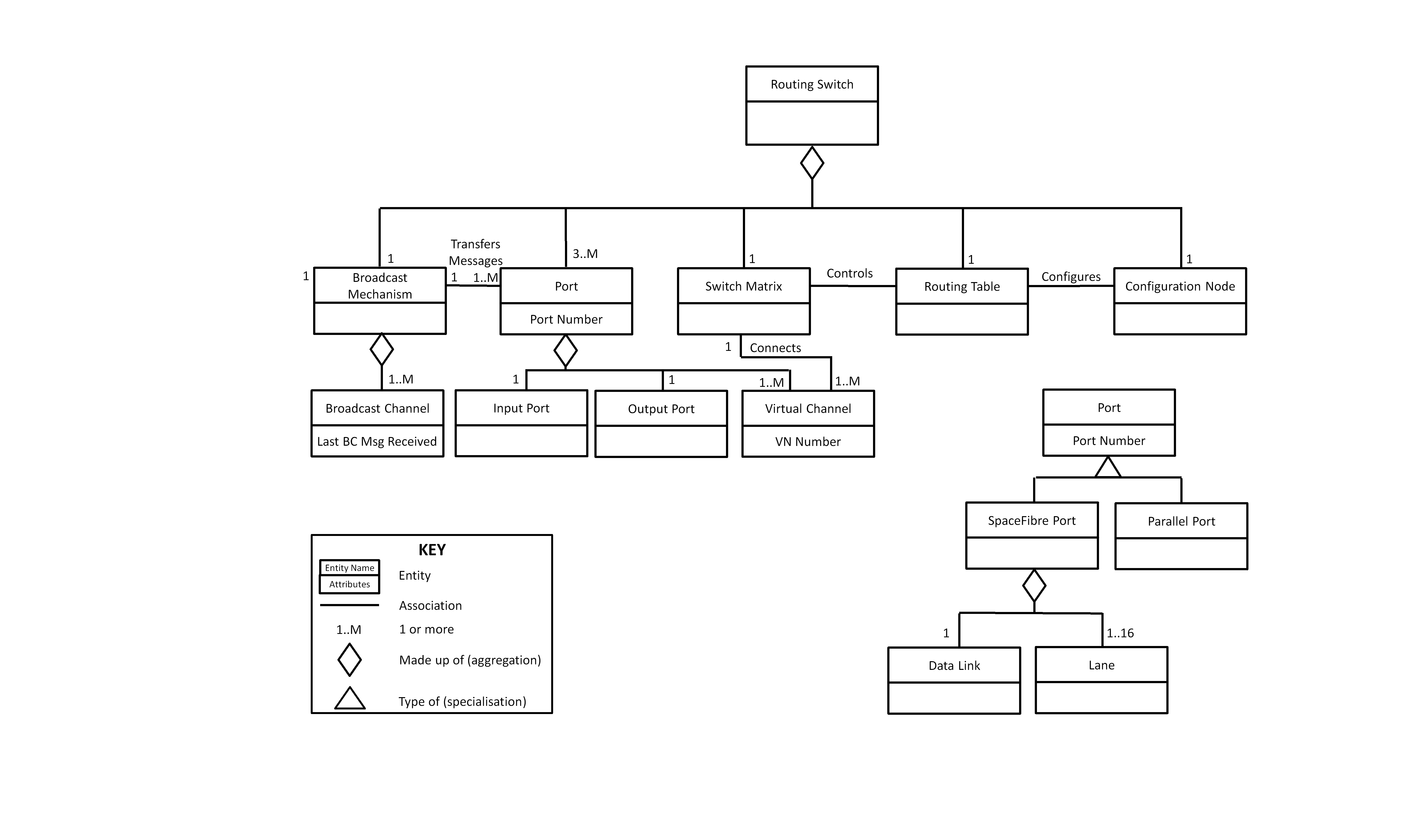 Figure 555: Components of a SpaceFibre routing switch
A port in a routing switch shall be bi-directional and contain an input port, an output port and one or more virtual channels.
A SpaceFibre port shall be made up of one data link and between one and sixteen lanes.
A virtual channel shall be configured to belong to a virtual network, by giving it a virtual network number.
The virtual network number maps the virtual channel to a virtual network.
A virtual channel shall pass packets received from the virtual network, associated with that virtual channel, to the switch matrix.
The switch matrix shall forward a packet to a virtual channel in the same or another port connected to the switch matrix.
The switch matrix shall only pass packets between virtual channels belonging to the same virtual network.
Virtual channels belonging to the same virtual network have the same virtual network number.
A virtual channel shall accept packets from the switch matrix for sending over the virtual network associated with that virtual channel.
All ports, except for the configuration port, shall contain at least two virtual channels in a port.
A port shall have a maximum of 32 virtual channels.
It shall be possible for the number of virtual channels in one port to be different from the number of virtual channels in another port.
A configuration node in the routing switch shall be used to configure, control and monitor the status of the routing switch.
When a routing switch is embedded in a unit, the configuration node in the routing switch may be used to configure, control and monitor the status of other equipment associated with the routing switch.
It is permitted for the configuration port of a routing switch embedded in some unit to be used to configure, control and monitor the unit, as well as configuring, controlling and monitoring the routing switch.
The configuration node in a routing switch shall be accessed via port 0, the configuration port, which is connected to the switch matrix.
The configuration port shall have only one virtual channel which is given the virtual network number VN0.
A routing switch configuration port shall be accessed using path addressing only.
The broadcast mechanism shall contain one or more broadcast channels.
Routing table
A routing switch shall use the leading data character of a packet to determine which output port the packet is forwarded through.
A routing table within the routing switch shall specify the mapping from the value of the leading data character to the output port or ports and also whether the leading data character is removed before the packet is switched to the output port.
The routing table shall interpret the leading data character of a SpaceFibre packet as specified in Table 535.
A leading data character with a value of 0 results in the packet being routed to the routing switch configuration port. A leading data character with a value of 6 results in the packet being routed to output port 6. A leading data character with a value of 49 results in the packet being routed to the output port that is referred to in location 49 of the routing table within the routing switch.
Table 535: Routing switch addresses
|
Leading data character
|
Address type
|
Port packet is routed to
|
Leading data character deletion
|
|
0
|
Path
|
Internal Configuration Port.
|
Always deleted.
|
|
1-31
|
Path
|
Physical Output Ports 1-31 respectively.
|
Always deleted.
|
|
32-254
|
Logical
|
A look-up table specifies the mapping from the leading data character, logical address, to the output port or ports the packet is forwarded through. There is one entry in this table for each value of the logical address, 32-255. Each entry is configured to specify the output port or ports to be used for each possible logical address.
|
A logical address is not normally deleted, unless it is part of a regional logical address, see clause 5.8.9.3. The leading data character is deleted if the physical output port is a gateway between distinct regions. The leading data character can also be deleted on final link to a node.
|
|
255
|
Logical
|
Reserved logical address, which is treated in the same way as any other logical address.
|
Treated in the same way as a logical address.
|
A configuration port shall be assigned port address 0.
SpaceFibre and parallel ports shall be assigned port addresses 1-31, so that there is a maximum of 31 external ports on a routing switch.
An invalid routing table entry shall be one that is undefined or not yet configured.
Address 255 is reserved for future use and shall not be used.
Routing switch operation
When a packet arrives at a routing switch the output port that it is forwarded through shall be determined from the leading data character of the packet and the routing table.
A packet shall be switched to the virtual channel in the specified output port that has the same virtual network number as the virtual channel on which the packet arrived in the routing switch input port.
The packet, therefore, remains within the same virtual network.
If the virtual channel in the output port is not currently transmitting a packet, it shall be allocated to transmit the newly arrived packet.
Allocating the packet to the output port effectively connects the input virtual channel to the output virtual channel.
Once a connection has been made between the input port virtual channel and the output port virtual channel, N-Chars and Fills shall be forwarded from the input virtual channel to the output virtual channel as they arrive, provided that the output virtual channel is able to accept them and considering Fill deletion.
Fill deletion is specified in clause 5.3.7.2.
If the output virtual channel is not able to accept more N-Chars and Fills, the input virtual channel shall hold them until the output virtual channel becomes ready to accept more N-Chars and Fills.
The connection between a virtual channel in an input port and a virtual channel in an output port shall not change until the packet that is currently being transmitted has finished being sent or is terminated following an error.
If a virtual channel in an input port is waiting for packet characters to arrive, the virtual channel in the output port that it is connected to shall also wait.
If the virtual channel in the needed output port is busy sending a packet from another input port, the newly arrived packet shall wait at the input port until the assigned output port is free to transmit the new packet.
If two or more input ports are waiting to send a packet to the same virtual channel in an output port, arbitration shall be used to determine which input port is allowed to send the next packet to that output virtual channel.
After a virtual channel in an output port has accepted the EOP or EEP at the end of a packet, that virtual channel output port shall be available to accept a packet from another input port.
If the specified output port does not have a virtual channel with the same virtual network number as that on which the packet arrived in the input port, the packet shall be discarded and an invalid output port error recorded by the routing switch.
A routing switch receiving an empty packet, shall discard it by deleting the second EOP or EEP.
An EOP or EEP received immediately after an EOP or EEP represents an empty packet which does not have a destination address.
Virtual channel time-out
A configurable virtual channel time-out shall be used by all virtual channels to detect a packet that has become stuck.
When available logic resources permit, a separate configurable virtual channel time-out may be used for each virtual channel.
A packet shall be regarded by a virtual channel as being stuck when the following conditions are all fulfilled:
- The first data character of the packet has been passed to the output virtual channel.
- The EOP or EEP for that packet has not yet been passed to the output virtual channel.
- The time since the last data character was sent from the input virtual channel to the output virtual channel is longer than the virtual channel time-out period. When a packet is stuck in a routing switch, the following actions shall be taken to clear the stuck packet:
- The packet currently being transferred is discarded by the input virtual channel.
- An EEP is placed in the output virtual channel. When a packet is stuck in a routing switch with virtual channel time-outs enabled, a stuck packet error condition should be registered.
The fact that this error has occurred can then be read via the routing switch configuration port.
The virtual channel time-out shall be able to be disabled, so that it does not time-out when a packet is stuck.
Routing switch reset
On reset of a routing switch the following shall occur:
- All ports are reset.
- Entries in the routing table for all logical addresses are set to not valid, so that a packet arriving with that logical address is discarded, until the corresponding entry in the routing table is configured.
- Virtual network to virtual channel mapping is set to default values.
- All configuration parameters are set to their default values.
- Header deletion for regional logical addressing is disabled.
- Group adaptive routing is disabled.
- Packet multicast is disabled.
Virtual network mapping is specified in clause 5.8.3. Default configuration parameters are detailed in clause 5.9.3. Group adaptive routing is specified in clause 5.8.10 and packet multicast in clause 5.8.11.
Packet addressing
Path addressing
A path address shall describe the path through the SpaceFibre network from the source of the packet to its destination.
Table 535 summarises the function of each type of address.
A path address shall comprise one or more data characters at the start of a packet, with each data character in the range 0-31.
The first data character specifies the output port of the first routing switch encountered by the packet, the second data character the output port of the second routing switch, and so on for all the routing switches on the path through the network from source to destination.
When the leading data character of a packet has a value of 0, the packet shall be routed to the routing switch configuration port.
When a SpaceFibre packet arrives at a routing switch and the leading data character is in the range 0 to 31, the leading data character shall be removed and replaced by the Fill character, and the packet switched out of the port indicated by that data character.
For example, a leading data character with a value of 6 results in the packet being routed to port 6. Removing the leading path address character after it has been used exposes the next path address character for use at the next router on the path to the destination.
If, after the leading data character has been removed and replaced by a Fill character, the first word of a packet contains only Fill characters, it shall be deleted.
The complete path address shall comprise a sequence of data characters, one for each router to be encountered on the path from the packet source to the packet destination.
A SpaceFibre routing switch shall support path addressing.
Logical addressing
A logical address shall comprise a single data character at the start of a packet, with a value in the range 32 to 255.
The logical address shall be used by all routing switches on the path from source to destination to look up the needed output port numbers in their routing tables.
Table 535 summarises the function of each type of address.
When a SpaceFibre packet arrives at a routing switch and the leading data character is in the range 32 to 255, the leading data character shall be used as an index into a routing table in the routing switch to determine which port the packet is forwarded through.
For example, a leading data character with a value of 49 results in entry 49 of the routing table specifying the output port that the packet is forwarded through. If entry 49 contains the value 7, the packet is forwarded through port 7.
Address 255 shall be reserved and not used.
The logical address shall not be removed from the packet when the packet is forwarded.
If regional logical address deletion is being used, see clause 5.8.9.3, it is possible to have more than one logical address at the start of a packet.
A SpaceFibre routing switch should support logical addressing.
Regional logical addressing
SpaceFibre shall also support regional logical addressing which is a special case of logical addressing.
A routing switch shall be configurable to remove the logical address character at the start of a packet and replace it with a Fill character when a packet is forwarded.
- 1 The deletion of a logical address is used to expand the number of nodes that can be accessed using logical addressing. A large network is divided into regions where a logical address applies. When crossing a boundary between regions, the logical address is deleted exposing a new logical address that applies to the next region. Regions using logical addressing can be connected to regions using path addressing. This mechanism enables more than 223 nodes to be accessed using a series of logical addresses.
- 2 A regional logic address can be used wherever a logical address is used.
When a leading character is deleted by a routing switch only one data character shall be deleted by that routing switch.
Addressing errors
If a port with a specific number does not exist in the routing switch, a packet arriving with a leading data character that references that non-existent port shall be discarded.
A packet arriving with a leading data character that references a non-existent port should result in an invalid address error being registered.
If the leading data character is a logical address that refers to an entry in the routing table that has not been configured or has been configured to refer to a port that does not exist in the routing switch, all the N-Chars in the packet shall be discarded as they are received by the routing switch.
A packet arriving with a leading data character that references an entry in the routing table which does not contain a valid port number should result in an invalid address error being registered.
The default behaviour of logical address 255 is the same as other logical addresses.
If an output port referenced by the leading data character of a packet does not have a virtual channel configured to the same virtual network as that on which the packet arrived, the packet shall be discarded and an invalid address error and invalid virtual network error registered.
Group adaptive routing
Group adaptive routing shall be optional in a routing switch.
A routing switch that supports group adaptive routing shall be able to route a packet with a logical address to one of several ports which is known as group adaptive routing.
A routing switch that supports group adaptive routing shall:
- Have entries for each logical address in the routing table which specify one or more output ports that a packet with that logical address is able to be routed to.
- Route a packet arriving with a leading data character that is a logical address to one port, from the set of ports specified in the routing table, which is ready to send packets, where the virtual channel, with the same virtual network number as that on which the packet arrived, is not currently being used to send a packet.
- When all of the set of output ports specified for a logical address are already sending packets over their virtual channels that have the same virtual network number as that on which the packet arrived, arbitrate between all the input ports waiting to use the specified set of output ports as each of the virtual channels in the output ports becomes free.
- When an input port wins the arbitration, connect its input virtual channel to the output virtual channel in the output port that it competed for. A routing switch shall not support group adaptive routing for path addresses.
Packet multicast
Packet multicast, sending of a particular packet to several destinations, shall be optional in a source node.
- 1 It is not necessary for a source node to implement packet multicast.
- 2 Use packet multicasting with extreme care, as it introduces many new ways to block or deadlock sections of a virtual network.
Packet multicast in a routing switch shall be optional.
It is not necessary for a routing switch to implement packet multicast.
A routing switch that supports packet multicast shall provide that support as follows:
- The routing table in the routing switch specifies the set of ports, the multicast set, that a packet with a particular logical address is sent through concurrently.
- When a packet arrives with a logical address that is configured for multicast, the packet is sent to each of the output ports in the multicast set.
- The packet to be multicast is sent to the designated output ports only when all of them are ready to accept a new packet.
- If one or more of the output ports in the multicast set is not ready, all the output ports wait and the packet is not sent to any of the multicast output ports until they are all ready.
When one or more of the ports in the multicast set are disabled, the routing switch should continue to forward packets to other ports in that multicast set.
Only virtual channels on the same virtual network shall be used for packet multicast.
Virtual channels are on the same virtual network when they are configured with the same virtual network number.
Broadcast messages
Broadcast channels
256 broadcast channels should be supported by each SpaceFibre router.
Each broadcast channel shall be identified by a broadcast channel number.
A broadcast message shall remain in the broadcast channel in which it was introduced in the network.
A broadcast channel shall be associated with one node or routing switch configuration node only.
The node or routing switch configuration node that is associated with a broadcast channel shall be the sole source of broadcast messages on that broadcast channel.
This means that a total of 256 nodes or routing switches can be sources of broadcast messages. Other nodes that are not sources of broadcast messages can be included in the network. The broadcast channel number indicates the source of the broadcast message.
It shall be possible for a node to not be associated with a broadcast channel, in which case that node is unable to send broadcast messages but is able to receive them.
Broadcast mechanism
When a broadcast message arrives at a routing switch, the port on which it arrived, port of arrival, shall be compared to the port on which the previous broadcast message arrived for the same broadcast channel, previous port of arrival.
The broadcast message shall be accepted to be broadcasted on any of the following conditions:
- It is the first broadcast message on that broadcast channel following reset of the routing switch.
- The port of arrival is the same as the previous port of arrival of the last accepted broadcast.
- It has been longer than the broadcast time-out interval since the last broadcast message on the same broadcast channel was accepted, and the LATE flag of the broadcast message is clear, indicating that the broadcast message is not late.
This method guarantees that the same broadcast message cannot be received more than once by the same node. It also does not limit the rate at which broadcast messages with the same channel can be generated, except in the case of a permanent link error or network topology change, in which case, the node has to wait for the duration of the broadcast time-out interval before sending a new broadcast message to ensure that the broadcast is not discarded.
The broadcast time-out interval shall be set to slightly longer than the time needed for a broadcast message to travel through the longest path of the network when all links in the network are operating.
A broadcast message shall be broadcast through the ports of the routing switch, excluding the port on which the broadcast message arrived.
A broadcast message shall only be broadcast through active ports of a routing switch which are enabled for message broadcasting.
SpaceFibre nodes
A SpaceFibre node shall act as any of the following:
- A source of packets and broadcast messages sent over a SpaceFibre network.
- A destination for packets and broadcast messages received over a SpaceFibre network.
- Both a source and destination of packets and broadcast messages. A SpaceFibre node shall comprise the following:
- One or more SpaceFibre ports or parallel ports, which each contain one or more virtual channels.
- One or more end-points, each of which provides an interface between a virtual channel of a port and the host system.
- Zero or one broadcast mechanism, which broadcasts broadcast-messages over the ports and broadcast-interface of the node.
- Zero or one broadcast interface, which provides the interface from applications hosted by the node to the broadcast mechanism.
The UML diagram in Figure 556 illustrates the components and specialisations of a SpaceFibre node.
 Figure 556: Components and specialisations of a SpaceFibre node
A port shall be bi-directional and contain an output port, an input port and one or more virtual channels.
An asymmetric multi-lane link, with more lanes in one direction than in the other, is still a bi-directional link and hence the ports at each end are bi-directional ports.
An end-point shall provide the means by which an application is able to interface to a virtual channel in a port and send and receive SpaceFibre packets over a network.
An end-point shall belong to the same virtual network as the virtual channel with which the end-point is associated.
To send a packet out of a port over a specific virtual network, the host system shall pass the packet to the port’s end-point that has its virtual channel mapped to the specific virtual network.
To receive a packet from a port sent over a specific virtual network, the host system shall read the packet from the port’s end-point that has its virtual channel mapped to the specific virtual network.
A SpaceFibre node shall support virtual network number VN0 and at least one other virtual network.
When logic resources are extremely limited, a SpaceFibre node may support only one virtual network.
A node with only one virtual network is not recommended, as many of the benefits of SpaceFibre are lost when only one virtual network is supported.
A configuration node shall have only one virtual channel which is assigned the virtual network number VN0.
A broadcast interface shall accept broadcast messages from an application for broadcasting over the SpaceFibre network using a broadcast channel.
A broadcast interface shall pass broadcast messages received over a broadcast channel from the SpaceFibre network to applications on the node.
SpaceFibre units
A SpaceFibre unit shall comprise zero or more nodes and zero or more routing switches.
A SpaceFibre unit shall comprise at least one node or routing switch.
The components of a SpaceFibre unit are illustrated in the UML diagram of Figure 557.
 Figure 557: Components and specialisations of a SpaceFibre unit
A SpaceFibre unit shall contain one or more applications which use the services of a SpaceFibre network.
Examples of a SpaceFibre unit include a routing switch, an instrument with a SpaceFibre interface, a processor with a SpaceFibre interface and a mass memory with either an internal SpaceFibre network connecting memory modules or external SpaceFibre interfaces.
Management Information Base
Management Information Base responsibilities
The SpaceFibre Management Information Base shall configure, control and monitor the operation of the other SpaceFibre layers.
Network management
The Remote Memory Access Protocol, (RMAP) in compliance with the ECSS-E-ST-50-52, shall be used for remote configuration, control and monitoring of SpaceFibre networks.
Network configuration, control and monitoring should be carried out using virtual network VN0 only.
Network configuration, control and monitoring shall only be carried out by network managers.
Only network managers shall be permitted to be RMAP initiators on virtual network VN0.
Since only VN0 is used for network configuration, control and monitoring and only network managers can be RMAP initiators on VN0, this prevents any other node from inadvertently accessing the configuration, control and monitoring space of the routing switches and nodes in a SpaceFibre network.
Configuration parameters
Configuration parameters shall be readable and writable via the management interface.
The configuration parameters listed in Table 536 shall be provided.
The configuration parameters shall be set to the value provided in Table 536 upon power-on or interface reset.
When an application requires specific default values, upon interface reset the configuration parameters may be set to values different to values specified in Table 536.
Table 536: SpaceFibre configuration parameters
|
Layer
|
Parameter
|
Description
|
Reset value
|
|
Network
|
Routing Table
|
Routing switch routing table which specifies for each logical address the port or ports that a packet is forwarded through.
|
All ports mapped to “invalid” indicating the logical address has not been programmed and a packet arriving with that logical address is discarded.
|
|
|
Router Virtual Network Mapping
|
Routing switch virtual network to virtual channel mapping for each port.
|
VN0 mapped to VC0, VN1 to VC1, and so on with VNy mapped to VCy.
|
|
Data Link
|
Priority level (VC)
|
Priority level assigned to a particular virtual channel.
|
The priority level with the lowest precedence which is supported by the implementation, e.g. 4 if there are four priority levels.
|
|
|
Normalised Expected Bandwidth (VC)
|
The fraction of overall link bandwidth assigned to a particular virtual channel.
|
See requirement 5.7.4.5r.
|
|
|
Allocated Time Slots (VC)
|
The time-slots in which a particular virtual channel is permitted to send data frames.
|
All ones
|
|
|
Virtual Channel Idle Time Limit
|
Determines the maximum time a channel can be idle without sending data before the underuse indication is raised. The period value can be hardcoded or can be provided by an optional configuration parameter for all VC channels or for each VC channel independently.
|
1 ms
|
|
Data Link
|
Bandwidth Credit Limit
|
Determines the maximum credit that can be accumulated by a virtual channel. When the maximum credit is reached the Bandwidth Credit Counter saturates and starts to forget the previous bandwidth utilisation of the link. The Bandwidth Credit Limit consequently determines how long the Bandwidth Credit Counter remembers previous use of bandwidth. This parameter is normally hardwired. If an implementation includes it as a management parameter, one value serves all virtual channels.
|
Implementation dependent
|
|
|
Normalised Expected Broadcast Bandwidth
|
The fraction of the overall link bandwidth assigned to broadcast messages.
|
10%
|
|
|
Continuous Mode (VC)
|
Indicates whether the virtual channel is set in Continuous mode (see requirement 5.7.2.2.h).
|
Not in Continuous Mode
|
|
|
DataScrambled
|
Determines whether data frames travelling over the SpaceFibre link are scrambled or not.
|
Scrambled
|
|
|
FCT Multiplier (M)
|
FCT Multiplier (M) is an integer in the range 1 to 8 which determines the value of each FCT. This parameter is normally hardwired. If an implementation includes it as a management parameter, it is only updated when the link is reset, i.e. when the Link Reset State Machine is not in Link Initialised state.
|
Set to 1, when the Multi-Lane layer is not implemented. Otherwise set to the value of the Maximum Number of Data-Sending Lanes parameter.
|
|
|
Data Segment Multiplier (N)
|
Data Segment Multiplier (N) is an integer less than or equal to the number of data-sending lanes in a link, including both active lanes and inactive lanes. This parameter is normally hardwired. If an implementation includes it as a management parameter, it is only updated when the link is reset, i.e. when the Link Reset State Machine is not in Link Initialised state.
|
Set to 1, when the Multi-Lane layer is not implemented. Otherwise set to the value of the Maximum Number of Data-Sending Lanes parameter.
|
|
Data Link
|
Link Reset
|
Performs a link reset, for example, when the link is disconnected from a device and then connected to a different device.
|
De-asserted
|
|
|
Interface Reset
|
Resets the link and all configuration parameters
|
N/A
|
|
Multi-Lane layer
|
Maximum Number of Data-Sending Lanes
|
The maximum number of data-sending lanes that are permitted in a link. This parameter is only acted upon following a link reset.
|
Implementation dependent
|
|
|
RxEn(lane)
|
Lanes that are able to receive.
|
Asserted for all lanes capable of receiving
|
|
|
TxEn(lane)
|
Lanes that are able to transmit.
|
Asserted for all lanes capable of transmitting
|
|
Lane Layer
|
Start mode (lane)
|
Asserts or de-asserts LaneStart for the corresponding lane.
|
De-asserted
|
|
|
Autostart (lane)
|
Asserts or de-asserts AutoStart for the corresponding lane.
|
Asserted
|
|
|
LaneReset (lane)
|
Asserts or de-asserts LaneReset for the corresponding lane.
|
De-asserted
|
|
|
Parallel Loopback (lane)
|
Enables or disables the parallel loopback for the corresponding lane.
|
De-asserted
|
|
|
Standby Reason (lane)
|
Reason for setting lane to standby. It sets bits 4 to 7 of the Standby Reason Field in the STANDBY control words. The values used are up to the user or implementation.
|
Bits 4 to 7 of the Standby Reason field are set to zero.
|
|
Physical Layer
|
Near-End Serial Loopback (lane)
|
Enables or disables the near-end serial loopback for the corresponding lane.
|
De-asserted
|
|
|
Far-End Serial Loopback (lane)
|
Enables or disables the far-end serial loopback for the corresponding lane.
|
De-asserted
|
Status parameters
Status parameters shall be readable via the management interface.
The mandatory status parameters shall be as listed in Table 537.
Implementations may provide additional status information for debugging purposes.
The way the status parameters are cleared shall be implementation dependent.
The status parameters shall be cleared on Link Reset Command.
Table 537: SpaceFibre status parameters
|
Layer
|
Parameter
|
Description
|
|
Network
|
Node End-Point Status
|
Status information for each end-point in a node.
|
|
Routing Switch Status
|
Status information for a routing switch.
| |
|
Data Link
|
BW over use (VC)
|
Indicates that the virtual channel is using much more bandwidth than expected and has reached the minimum bandwidth credit value.
|
|
|
BW under use (VC)
|
Indicates that the virtual channel is using less bandwidth than expected and that the bandwidth credit has remained at its maximum value for a certain time, the Virtual Channel Idle Time Limit.
|
|
|
Has Credit (VC)
|
Indicates that there is space in the input buffer at the other end of the link, the destination.
|
|
|
Input buffer overflow (VC)
|
Indicates that an input buffer is receiving data when it is full. This ought not to happen and indicates a fatal protocol error.
|
|
|
FCT Credit Counter overflow (VC)
|
Indicates that the FCT credit counter for a particular virtual channel has overflowed.
|
|
|
16-bit CRC error
|
Set when a 16-bit CRC error has occurred. This indicates that one or multiple lanes are receiving multiple bit errors, which is not expected under nominal operation.
|
|
|
Frame Error
|
Set when a Frame error has occurred as indicated by the Data words identification state machine.
|
|
|
CRC-8 error
|
Set when a CRC-8 error occurs. This can occur under nominal operation.
|
|
|
Sequence error
|
Set when a sequence error occurs. This can occur under nominal operation.
|
|
|
Error recovery buffer empty
|
Set when the error recovery buffer is empty. This indicates that all data frames, broadcast frames and FCTs that have been sent have been acknowledged.
|
|
Data Link
|
Number of error recovery attempts
|
The number of error recovery attempts made by the SpaceFibre port. Incremented by one for every error recovery attempt that is initiated.
|
|
|
Link Reset Caused by Protocol Error
|
Set when an ACK or NACK is received with an inconsistent Sequence Count.
|
|
|
Far-End Link Reset
|
Set when the Link Reset state machine at the near-end of the link, moves from the Link Initialised state to the Near-End Reset state, because the Lane Capability information is received from the Lane or Multi-Lane layer with the INIT3LinkResetFlag field set to 1.
|
|
Multi-Lane Layer
|
Data-sending lanes
|
Indicates which lanes are data-sending lanes
|
|
|
Data-receiving lanes
|
Indicates which lanes are data-receiving lanes
|
|
|
Alignment State
|
State of Alignment state machine.
|
|
Lane Layer
|
Lane State (lane)
|
Indicates the current state of the Lane Initialisation state machine in a lane.
|
|
|
RXERR Counter (lane)
|
Value of the RXERR word counter. Can be used to obtain the current BER.
|
|
|
RXERR Overflow (lane)
|
Set when RXERR word counter overflows in Active state.
|
|
|
Far-End Standby (lane)
|
Set when the STANDBY words are received from the far-end of the link, indicating that the far-end is going into standby. Optionally, the Standby Reason can be provided.
|
|
|
Timeout (lane)
|
Set when a connection timeout occurs.
|
|
|
Far-End Lost Signal (lane)
|
Set when LOST SIGNAL control words are received from the far-end of the link, indicating that the far-end has lost the signal from the near-end. Optionally, the value of the Reason field of the LOST SIGNAL control words can be provided.
|
|
|
Far-End Capabilities (lane)
|
Reports the value of the Capabilities field of the last correctly received INIT3 control word.
|
|
|
RX Polarity
|
Set when the receiver polarity is inverted.
|
|
Physical Layer
|
NoSignal (lane)
|
Asserted when no signal is detected at the receiver.
|
|
|
Bit-synchronisation (lane)
|
Indicates when bit synchronisation is achieved.
|
Service interfaces
Overview
Clause 6 provides the service interfaces to the OSI layers of the SpaceFibre standard, which are the Network layer, Data-Link layer and Physical layer. Note that in the OSI model the Multi-Lane layer and Lane layer are sub-layers of the Data Link layer so do not have service interfaces. A service interface to the Management Information Base is also provided.
Network layer service interface
Network layer services
The services that shall be associated with the Network layer are:
- Packet Transfer service.
- Broadcast message service.
Packet Transfer service
Service primitives
The service primitives that shall be associated with the Packet Transfer service are:
- SEND_PACKET.request.
- READ_PACKET.indication.
SEND_PACKET.request
Function
The SEND_PACKET.request primitive shall be used to send a SpaceFibre packet across a SpaceFibre network through a virtual network.
Semantics
The SEND_PACKET.request primitive shall provide the following parameters:
- SEND_PACKET.request (Virtual Network, SpaceFibre Packet).
When generated
When the user has a packet to send over the SpaceFibre network, it shall generate a SEND_PACKET.request primitive to request to send a SpaceFibre packet over the network using a specific virtual network.
Effect on receipt
On receipt of the SEND_PACKET.request primitive the SpaceFibre node receiving the request shall send the SpaceFibre packet over the SpaceFibre network using the specified virtual network.
READ_PACKET.indication
Function
A SpaceFibre node receiving a SpaceFibre packet shall pass a READ_PACKET.indication primitive to the Read SpaceFibre Packet Transfer service user to indicate that a SpaceFibre packet has arrived over a particular virtual network and is waiting to be read.
Semantics
The READ_PACKET.indication primitive shall have the following parameters:
- READ_PACKET.indication (Virtual Network, SpaceFibre Packet, Terminated by EEP).
When generated
The READ_PACKET.indication primitive shall be passed to the Read Packet Transfer service user when a SpaceFibre packet is received.
Effect on receipt
The effect on receipt of the RX_PACKET.indication primitive by the Read Packet Transfer service user shall be that the service user reads the received SpaceFibre packet.
Broadcast message service
Service primitives
The service primitives that shall be associated with the broadcast message service are:
BROADCAST_MESSAGE.request.BROADCAST_MESSAGE.indication.#### BROADCAST_MESSAGE.request
Function
The BROADCAST_MESSAGE.request primitive shall be used by the SpaceFibre network layer to request a SpaceFibre node to send a broadcast message over the SpaceFibre network.
Semantics
The BROADCAST_MESSAGE.request primitive shall provide the following parameters:
- BROADCAST_MESSAGE.request (Broadcast Channel, Broadcast Type, Message).
When generated
When the SpaceFibre user has a broadcast message to send it shall generate a BROADCAST_MESSAGE.request primitive to request a SpaceFibre node to send the broadcast message of a particular type over a specific broadcast channel.
Effect on receipt
On receipt of the BROADCAST_MESSAGE.request primitive the SpaceFibre node shall send the broadcast message over the specified broadcast channel immediately, subject to link priority rules.
BROADCAST_MESSAGE.indication
Function
The function of the BROADCAST_MESSAGE.indication primitive shall be to indicate to the SpaceFibre user that a broadcast message has arrived over a particular broadcast channel and to pass that message to the SpaceFibre user.
Semantics
The BROADCAST_MESSAGE.indication primitive shall have the following parameters:
- BROADCAST_MESSAGE.indication (Broadcast Channel, Broadcast Type, STATUS, Message).
When generated
The BROADCAST_MESSAGE.indication primitive shall be passed to the SpaceFibre user, when a valid broadcast message is received.
Effect on receipt
The effect on receipt of the BROADCAST_MESSAGE.indication primitive by the SpaceFibre user shall be for the user to read the broadcast message.
Data Link layer service interface
Data Link layer services
The services that shall be associated with the Data Link layer are:
- Virtual Channel service.
- Broadcast Message service.
- Schedule synchronisation service.
Virtual Channel service
Service primitives
The service primitives that shall be associated with the Virtual Channel service are:
- TX_N-CHAR.request.
- RX_N-CHAR.indication.
TX_ N-CHAR.request
Function
The TX_N-CHAR.request primitive shall be used to send an N-Char or Fill through a Virtual Channel of a SpaceFibre link.
Semantics
The TX_N-CHAR.request primitive shall provide the following parameters:
- TX_N-CHAR.request (Virtual Channel, N-Char/Fill).
When generated
When the user has an N-Char or Fill to send over a specific virtual channel of the SpaceFibre link, it shall generate a TX_N-CHAR.request primitive to request to send the N-Char or Fill over that Virtual Channel.
Effect on receipt
On receipt of the TX_N-CHAR.request primitive, the SpaceFibre interface shall send the N-Char or Fill over the specified Virtual Channel as soon as permitted by the SpaceFibre medium access controller.
RX_N-CHAR.indication
Function
The SpaceFibre interface shall pass an RX_N-CHAR.indication primitive to the SpaceFibre network layer to indicate that an N-Char or Fill has arrived over a particular Virtual Channel.
Semantics
The RX_N-CHAR.indication primitive shall have the following parameters:
- RX_N-CHAR.indication (Virtual Channel, N-Char/Fill).
When generated
The RX_N-CHAR.indication primitive shall be passed to the SpaceFibre network layer when an N-Char or Fill is received.
Effect on receipt
The effect on receipt of the RX_N-CHAR.indication primitive by the SpaceFibre network layer shall be that the received N-Char or Fill is read from the specified Virtual Channel by the SpaceFibre network layer.
Broadcast message service
Service primitives
The service primitives that shall be associated with the broadcast channel service are:
- TX_BROADCAST.request.
- RX_BROADCAST.indication.
TX_BROADCAST.request
Function
The TX_BROADCAST.request primitive shall be used by the SpaceFibre network layer to request the SpaceFibre interface to send a broadcast message through a SpaceFibre broadcast channel.
Semantics
The TX_BROADCAST.request primitive shall provide the following parameters:
- TX_BROADCAST.request (Broadcast Channel, Broadcast Type, STATUS, Message).
When generated
When the SpaceFibre network layer has a broadcast message to send it shall generate a TX_BROADCAST.request primitive to request the SpaceFibre interface to send the broadcast message over a specific broadcast channel.
Effect on receipt
On receipt of the TX_BROADCAST.request primitive the SpaceFibre interface shall send the broadcast message over the specified broadcast channel as soon as the current word has been sent or, when a broadcast frame is already being sent, at the end of that broadcast frame.
RX_BROADCAST.indication
Function
The function of the RX_BROADCAST.indication primitive shall be to indicate to the SpaceFibre network layer that a broadcast message has arrived over a particular broadcast channel and to pass that message to the SpaceFibre network layer.
Semantics
The RX_BROADCAST.indication primitive shall have the following parameters:
- RX_BROADCAST.indication (Broadcast Channel, Broadcast Type, STATUS, Message).
When generated
The RX_BROADCAST.indication primitive shall be passed to the SpaceFibre network layer, when a valid broadcast message is received.
Effect on receipt
The effect on receipt of the RX_BROADCAST.indication primitive by the SpaceFibre network layer shall be for the network layer to validate and forward valid broadcast messages.
Schedule synchronisation service
Service primitives
The service primitives that shall be associated with the schedule synchronisation service are:
- SCHEDULE.request.
SCHEDULE.request
Function
The SCHEDULE.request primitive shall be used by the SpaceFibre network layer to pass current time-slot information to the Data Link layer in order to synchronise the scheduled QoS in each Data Link of a network.
Semantics
The SCHEDULE.request primitive shall provide the following parameters:
- SCHEDULE.request (Time-Slot).
When generated
When a routing switch or node receives new time-slot information within a broadcast message, the SpaceFibre network layer shall generate a SCHEDULE.request primitive to inform the Data Link layer of the value of the new time-slot.
Effect on receipt
On receipt of the SCHEDULE.request primitive the Data Link layer shall use the time-slot information to end the previous time-slot and start the next one.
Physical layer service interfaces
Physical layer services
The services that shall be associated with the Physical layer are:
- Transfer Symbols service.
- Control service.
Transfer symbols service
Service primitives
The service primitives that shall be associated with the Transfer Symbols service are:
- TX_SYMBOL.request.
- RX_10BITS.indication.
TX_SYMBOL.request
Function
The Lane layer shall pass a TX_SYMBOL.request primitive to the Physical layer to send a symbol over the SpaceFibre link.
Semantics
The TX_SYMBOL.request primitive shall provide the following parameters:
- TX_SYMBOL.request (Symbol).
When generated
The TX_SYMBOL.request primitive shall be passed to the Physical layer when the Lane layer has a symbol to send over the SpaceFibre link.
Effect on receipt
On receipt of the TX_SYMBOL.request primitive the Physical layer shall serialise the symbol and send it over the SpaceFibre link.
RX_10BITS.indication
Function
The Physical layer shall pass an RX_10BITS.indication primitive to the Lane layer to indicate that a symbol has been received and de-serialised.
Semantics
The RX_10BITS.indication primitive shall have the following parameters:
- RX_10BITS.indication (10-bits).
When generated
The RX_10BITS.indication primitive shall be passed to the Lane layer when a symbol is received over the SpaceFibre link and de-serialised.
Effect on receipt
The effect on receipt of the RX_10BITS.indication primitive by the Physical layer shall be that the symbol is passed to the Lane layer.
Control service
Service primitives
The service primitives that shall be associated with the Control service are:
- PHYSICAL_CONTROL.request.
- PHYSICAL_STATUS.indication.
PHYSICAL_CONTROL.request
Function
The Lane layer shall pass a PHYSICAL_CONTROL.request primitive to the Physical layer to control the operation of the Physical layer.
Semantics
The PHYSICAL_CONTROL.request primitive shall provide the following parameters:
- PHYSICAL_CONTROL.request (Enable TX, Enable RX, Invert RX Polarity).
When generated
The PHYSICAL_CONTROL.request primitive shall be passed to the Physical layer when the Lane layer needs to control the operation of the Physical layer.
Effect on receipt
On receipt of the PHYSICAL_CONTROL.request primitive the Physical layer shall set the operating mode of the Physical layer according to the control parameters passed in the PHYSICAL_CONTROL.request primitive.
PHYSICAL_STATUS.indication
Function
The Physical layer shall pass a PHYSICAL_STATUS.indication primitive to the Lane layer to indicate that the status of the Physical layer has changed.
Semantics
The PHYSICAL_STATUS.indication primitive shall have the following parameters:
- PHYSICAL_STATUS.indication (LossOfSignal).
When generated
The PHYSICAL_STATUS.indication primitive shall be passed to the Lane layer when the Physical layer status has changed.
Effect on receipt
On receipt of the PHYSICAL_STATUS.indication primitive the Lane layer shall react depending on the Physical layer status.
Management Information Base service interface
Management Information Base services
The services that shall be associated with the Management Information Base are:
- Link Management service.
Link Management service
Service primitives
The service primitives that shall be associated with the Link Management service are:
- SET_MANAGEMENT_PARAMETER.request.
- GET_MANAGEMENT_PARAMETER.request.
SET_MANAGEMENT_PARAMETER.request
Function
The function of the SET_MANAGEMENT_PARAMETER.request primitive shall be to set a management parameter of a SpaceFibre node or routing switch on the SpaceFibre network.
Semantics
The SET_MANAGEMENT_PARAMETER.request primitive shall provide parameters as follows:
- SET_MANAGEMENT_PARAMETER.request (Parameter Identifier, New Parameter Value).
When generated
The SET_MANAGEMENT_PARAMETER.request primitive shall be generated to change a management parameter in the SpaceFibre port.
Effect on receipt
The effect on receipt of the SET_MANAGEMENT_PARAMETER.request primitive shall be to update the specified management parameter with the new value provided in the request.
GET_MANAGEMENT_PARAMETER.request
Function
The function of the GET_MANAGEMENT_PARAMETER.request primitive shall be to get the value of a management parameter from the SpaceFibre interface.
Semantics
The GET_MANAGEMENT_PARAMETER.request primitive shall provide parameters as follows:
- GET_MANAGEMENT_PARAMETER.request (Parameter Identifier).
When generated
The GET_MANAGEMENT_PARAMETER.request primitive shall be generated to read the value of a management parameter in the SpaceFibre interface.
Effect on receipt
The effect on receipt of the GET_MANAGEMENT_PARAMETER.request primitive shall be for the SpaceFibre interface to provide the value of the specified management parameter.
Bibliography
|
ECSS-ST-S-00
|
ECSS system - Description, implementation and general requirements
|
|
ECSS-E-ST-50-12
|
Space engineering - SpaceWire - Links, nodes, routers and networks
|
|
HFAN-4.0.2
|
Maxim Integrated Application Note HFAN-4.0.2, Converting between RMS and Peak-to-Peak Jitter at a Specified BER, Rev.2, April 2008.
|
|
HFAN-4.0.3
|
Maxim Integrated Application Note HFAN-4.0.3, Jitter in Digital Communication Systems, Part 1, Rev.1, April 2008.
|
|
HFAN-4.0.4
|
Maxim Integrated Application Note HFAN-4.0.4, Jitter in Digital Communication Systems, Part 2, Rev.0, March 2002.
|
|
Texas Instruments, Application Report SLLA120, December 2002, N. Holland
|
Interfacing Between LVPECL, VML, CML, and LVDS Levels
|