
Space engineering
Space data links - Telemetry synchronization and channel coding
Foreword
This Standard is one of the series of ECSS Standards intended to be applied together for the management, engineering and product assurance in space projects and applications. ECSS is a cooperative effort of the European Space Agency, national space agencies and European industry associations for the purpose of developing and maintaining common standards. Requirements in this Standard are defined in terms of what shall be accomplished, rather than in terms of how to organize and perform the necessary work. This allows existing organizational structures and methods to be applied where they are effective, and for the structures and methods to evolve as necessary without rewriting the standards.
This Standard has been prepared by the ECSS-E-ST-50-01C Working Group, reviewed by the ECSS Executive Secretariat and approved by the ECSS Technical Authority.
Disclaimer
ECSS does not provide any warranty whatsoever, whether expressed, implied, or statutory, including, but not limited to, any warranty of merchantability or fitness for a particular purpose or any warranty that the contents of the item are error-free. In no respect shall ECSS incur any liability for any damages, including, but not limited to, direct, indirect, special, or consequential damages arising out of, resulting from, or in any way connected to the use of this Standard, whether or not based upon warranty, business agreement, tort, or otherwise; whether or not injury was sustained by persons or property or otherwise; and whether or not loss was sustained from, or arose out of, the results of, the item, or any services that may be provided by ECSS.
Published by: ESA Requirements and Standards Division
ESTEC, ,
2200 AG Noordwijk
The
Copyright: 2008 © by the European Space Agency for the members of ECSS
Change log
|
ECSS-E-50-01A
|
First issue
|
|
ECSS-E-50-01B
|
Never issued
|
|
ECSS-E-ST-50-01C
|
Second issue
|
Scope
This Standard establishes a common implementation of space telemetry channel coding systems.
Several space telemetry channel coding schemes are specified in this Standard. The specification does not attempt to quantify the relative coding gain or the merits of each scheme, nor the design requirements for encoders or decoders. However, some application profiles are discussed in Annex D. Performance data for the coding schemes specified in this Standard can be found in CCSDS 130.1G1. Annex G describes the related mission configuration parameters.
Further provisions and guidance on the application of this standard can be found in the following publications:
ECSS-E-ST-50, Communications, which defines the principle characteristics of communication protocols and related services for all communication layers relevant for space communication (physical- to application-layer), and their basic relationship to each other.
The handbook ECSS-E-HB-50, Communications guidelines, which provides information about specific implementation characteristics of these protocols in order to support the choice of a certain communications profile for the specific requirements of a space mission.
Users of this present standard are invited to consult these documents before taking decisions on the implementation of the present one.
This standard may be tailored for the specific characteristics and constraints of a space project in conformance with ECSS-S-ST-00.
Normative references
The following normative documents contain provisions which, through reference in this text, constitute provisions of this ECSS Standard. For dated references, subsequent amendments to, or revisions of any of these publications, do not apply. However, parties to agreements based on this ECSS Standard are encouraged to investigate the possibility of applying the most recent editions of the normative documents indicated below. For undated references the latest edition of the publication referred to applies.
|
ECSS-S-ST-00-01
|
ECSS system - Glossary of terms
|
Terms, definitions and abbreviated terms
Terms from other standards
For the purpose of this Standard, the terms and definitions from ECSSST0001 apply.
Terms specific to the present standard
category A
category of spacecraft having an altitude above the Earth’s surface less than 2 × 10⁶ km
category B
category of spacecraft having an altitude above the Earth’s surface equal to, or greater than 2 × 10⁶ km
octet
group of eight bits
- 1 The numbering for octets within a data structure starts with 0.
- 2 Refer to clause 3.4 for the convention for the numbering of bits.
physical channel
stream of bits transferred over a space link in a single direction
Abbreviations
For the purpose of this Standard, the abbreviated terms from ECSSSST0001and the following apply:
|
Abbreviation
|
Meaning
|
|
8PSK
|
phase shift keying of eight states
|
|
AOS
|
advanced orbiting systems
|
|
APP
|
a posteriori probability
|
|
ASM
|
attached sync marker
|
|
AWGN
|
additive white Gaussian noise
|
|
BER
|
bit error rate
|
|
BPSK
|
binary phase shift keying
|
|
CADU
|
channel access data unit
|
|
CCSDS
|
Consultative Committee for Space Data Systems
|
|
CRC
|
cyclic redundancy check
|
|
FER
|
frame error rate
|
|
GF(n)
|
Galois field consisting of exactly n elements
|
|
GMSK
|
Gaussian minimum shift keying
|
|
MSB
|
most significant bit
|
|
MS/S
|
mega symbols per second
|
|
NRZ-L
|
non-return to zero level
|
|
NRZ-M
|
non-return to zero mark
|
|
QPSK
|
quadrature phase shift keying
|
|
RS
|
Reed-Solomon
|
|
TCM
|
trellis-coded modulation
|
Conventions
3.4.1 bit 0, bit 1, bit N1
To identify each bit in an N-bit field, the first bit in the field to be transferred (i.e. the most left justified in a graphical representation) is defined as bit 0; the following bit is defined as bit 1 and so on up to bit N1.
 Figure 31: Bit numbering convention
3.4.2 most significant bit
When an N-bit field is used to express a binary value (such as a counter), the most significant bit is the first bit of the field, i.e. bit 0 (see Figure 31).
Overview
Introduction
Telemetry channel coding is a method of processing data that is sent from a source to a destination so that distinct messages are created that are easily distinguishable from one another and thus enable reconstruction of the data with low error probability, thus improve the performance of the channel.
Coding
Channel codes
A channel code is the set of rules that specify the transformation of elements of a source alphabet to elements of a code alphabet. The elements of the source alphabet and of the code alphabet are called symbols.
Depending on the code, the symbols can consist of one or more bits. The source symbols are also called information symbols. The code symbols are called channel symbols when they are the output of the last or only code applied during the encoding process.
Block encoding is a one-to-one transformation of sequences of length k source symbols to sequences of length n code symbols. The length of the encoded sequence is greater than the source sequence, so n> k.
The ratio k/n is the code rate, which can be defined more generally as the average ratio of the number of binary digits at the input of an encoder to the number of binary digits at its output.
A codeword of an (n,k) block code is one of the sequences of n code symbols in the range of the one-to-one transformation.
A codeblock of an (n,k) block code is a sequence of n channel symbols which are produced as a unit by encoding a sequence of k information symbols. The codeblock is decoded as a unit and, if successful, delivers a sequence of k information symbols.
A systematic code is one in which the input information sequence appears in unaltered form as part of the output codeword.
A transparent code has the property that complementing the input of the encoder or decoder results in complementing the output.
Connection vectors
Convolutional and turbo coding use connection vectors.
A forward connection vector is a vector which specifies one of the parity checks computed by the shift register(s) in the encoder. For a shift register with s stages, a connection vector is an s-bit binary number. A bit equal to "1" in position i (counted from the left) indicates that the output of the ith stage of the shift register is used in computing that parity check.
In turbo coding, a backward connection vector is a vector which specifies the feedback to the shift registers in the encoder. For a shift register with s stages, a backward connection vector is an s-bit binary number. A bit equal to "1" in position i (counted from the left) indicates that the output of the ith stage of the shift register is used in computing the feedback value, except for the leftmost bit which is ignored.
Convolutional codes
A convolutional code is a code in which a number of output symbols are produced for each input information bit. Each output symbol is a linear combination of the current input bit as well as some or all of the previous k1 bits, where k is the constraint length of the code. The constraint length is the number of consecutive input bits that are used to determine the value of the output symbols at any time.
The rate 1/2 convolutional code is specified in clause 5. Depending on performance requirements, this code can be used alone.
For telecommunication channels that are constrained by bandwidth and cannot accommodate the increase in bandwidth caused by the basic convolutional code, clause 5 also specifies a punctured convolutional code which has the advantage of a smaller bandwidth expansion.
A punctured code is a code obtained by deleting some of the parity symbols generated by the convolutional encoder before transmission. There is an increase in the bandwidth efficiency due to puncturing compared to the original code, however the minimum weight (and therefore its error-correcting performance) is less than that of the original code.
Reed-Solomon codes
The Reed-Solomon (R-S) code specified in clause 6 is a powerful burst error correcting code. In addition, the code has the capability of indicating the presence of uncorrectable errors, with an extremely low undetected error rate.
The Reed-Solomon code has the advantage of smaller bandwidth expansion than the convolutional code.
The Reed-Solomon symbol is a set of J bits that represents an element in the Galois field GF(2J), the code alphabet of a J-bit Reed-Solomon code. For the code specified in clause 6, J = 8 bits per RS symbol.
Concatenated codes
Concatenation is the use of two or more codes to process data sequentially, with the output of one encoder used as the input to the next.
In a concatenated coding system, the first encoding algorithm that is applied to the data stream is called the outer code.
The last encoding algorithm that is applied to the data stream is called the inner code. The data stream that is input to the inner encoder consists of the codewords generated by the outer encoder.
To achieve a greater coding gain than the one that can be provided by the convolutional code or Reed-Solomon code alone, a concatenation of the convolutional code as the inner code with the Reed-Solomon code as the outer code can be used for improved performance.
This Standard also specifies the concatenation of the Reed-Solomon code with the 4-dimensional 8PSK trellis-coded modulation (4D-8PSK-TCM) defined in ECSS-E-ST-50-05. In this case, the Reed-Solomon code with E=8 is the outer code and the 4D-8PSK-TCM is the inner code.
Turbo codes
A turbo code is a block code formed by combining two component recursive convolutional codes. A turbo code takes as input a block of information bits. The input block is sent unchanged to the first component code and bit-wise interleaved to the second component code. The interleaving process, called the turbo code permutation, is a fixed bit-by-bit permutation of the entire input block.
The output is formed by the parity symbols contributed by each component code plus a replica of the information bits.
The turbo codes specified in clause 7 can be used to increase the coding gain in cases where the environment tolerates the bandwidth overhead.
Synchronization and pseudo-randomization
The methods for synchronization specified in clause 8 apply to all telemetry channels, coded or uncoded. An attached sync marker (ASM) is attached to the codeblock or transfer frame. The ASM can also be used for resolution of data ambiguity (sense of ‘1’ and ‘0’) if data ambiguity is not resolved by the modulation method used.
Successful bit synchronization at the receiving end depends on the incoming signal having a minimum bit transition density. Clause 9 specifies the method of pseudo-randomizing the data to improve bit transition density.
Figure 41 and Figure 42 provide an overview of how pseudo-randomization and synchronization are combined with the different coding options at the sending and receiving end.
At the sending end, the order of convolutional encoding and modulation is dependent on the implementation. At the receiving end, the order of demodulation, frame synchronization and convolutional decoding are dependent on the implementation.
The figures do not imply any hardware or software configuration in a real system. When designing a communications system, the system designer usually takes into account radio regulations and modulation standardization requirements from other standards, such as ECSS-E-ST-50-05.
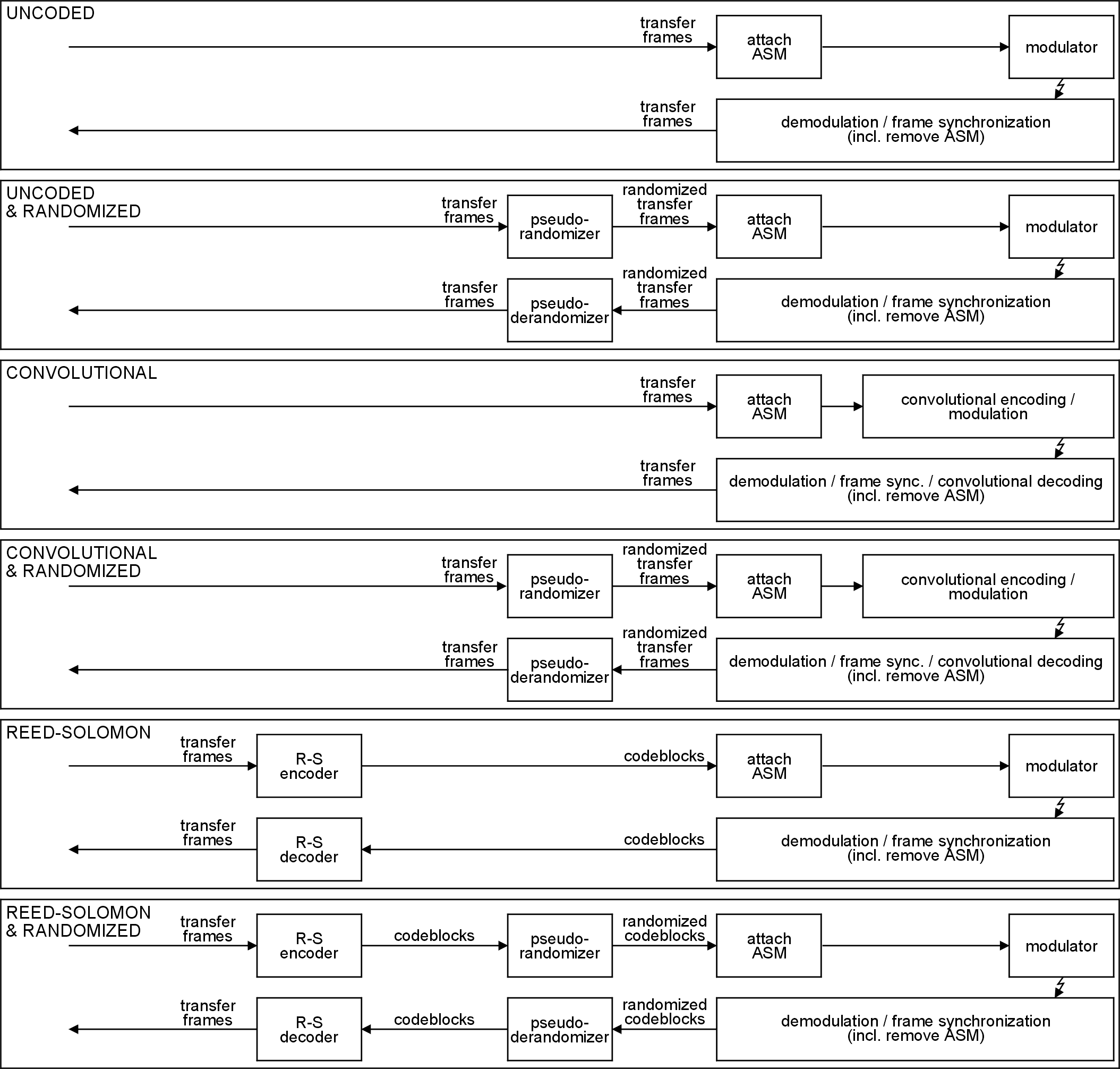 Figure 41: Coding, randomization and synchronization (1)
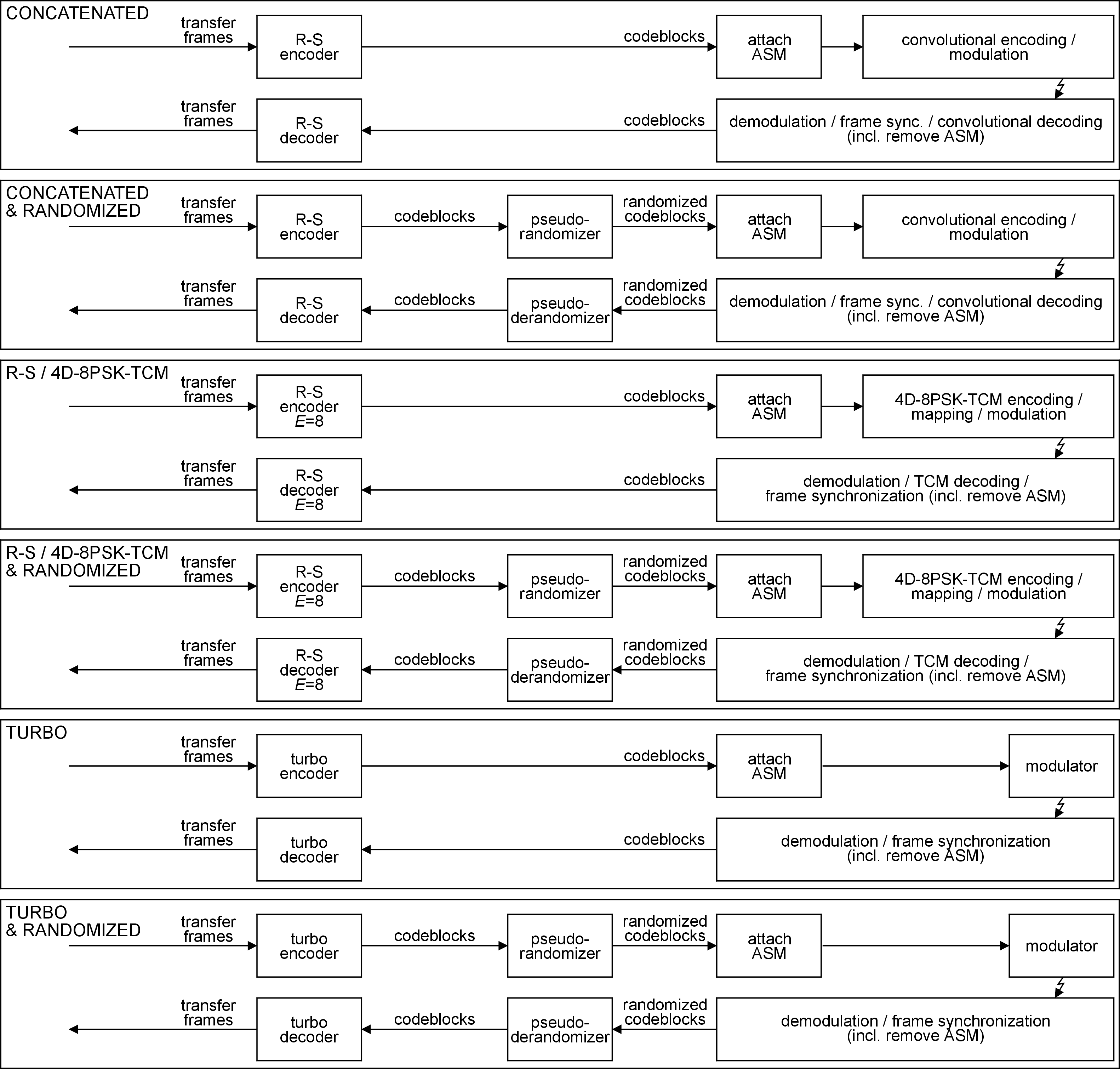 Figure 42: Coding, randomization and synchronization (2)
Convolutional coding
Properties
Convolutional coding is suitable for channels with predominantly Gaussian noise.
The basic convolutional code defined in clause 5.3 is a rate 1/2, constraint-length 7 transparent code. The basic code can be modified by puncturing, which removes some of the symbols before transmission, thus providing lower overhead and lower bandwidth expansion than the original code, but with reduced error correcting performance. The punctured convolutional codes are defined in clause 5.4
The codes are non-systematic. The convolutional decoder is a maximum-likelihood decoder using the Viterbi decoding scheme. Decoding failures are not signalled and produce error bursts.
The requirements in clause 5.2 apply to the basic and punctured convolutional codes.
The convolutional code, by itself, cannot guarantee sufficient symbol transitions when non-binary modulation schemes such as QPSK are used. The pseudo-randomizer defined in clause 9 can be used to increase the symbol transition density.
If the decoder's correction capability is exceeded, undetected burst errors can appear in the output. For this reason, when telemetry transfer frames are used, reference ECSS-E-ST-50-03 specifies that a cyclic redundancy check (CRC) field be used to validate the frame unless the Reed-Solomon code is used. Similarly, the CRC is used for the AOS transfer frames defined in CCSDS 732.0-B-2.
General
Soft bit decisions with at least 3-bit quantization shall be used for the decoder.
The frame synchronization defined in clause 8 shall be used.
If differential encoding (i.e. conversion from NRZ-L to NRZ-M) is used at the sending end, the conversions should be as follows:
the conversion is performed at the input to the convolutional encoder;
the corresponding conversion at the receiving end from NRZ-M to NRZ-L is performed at the output of the convolutional decoder.
- 1 This prevents avoidable link performance loss.
- 2 When suppressed-carrier modulation systems are used, NRZ-M or NRZ-L can be used as a modulating waveform. In NRZ-M a data "1" is represented by a change in level and a data "0" is represented by no change in level. In NRZ-L a data "1" is represented by one of two levels, and a data "0" is represented by the other level.
- 3 When a fixed pattern (the fixed part of the convolutionally encoded attached sync marker) in the symbol stream is used to provide node synchronization for the Viterbi decoder, the modulating waveform conversion can cause a modification of the pattern.
Basic convolutional code
The basic convolutional code shall have the characteristics shown in Table 51.
- 1 The encoding rule can be represented by the following equations:
s1(t) = i(t) + i(t1) + i(t2) + i(t3) + i(t6) modulo 2
s2(t) = i(t) + i(t2) + i(t3) + i(t5) + i(t6) + 1 modulo 2
where the equations use modulo 2 addition, and s1 is the first output symbol, s2 is the second output symbol and i(t) is the input information at time t.
- 2 An encoder block diagram is shown in Figure 51.
- 3 The output symbol sequence is:
C1(1), , C1(2), . . . .
Table 51: Basic convolutional code characteristics
|
Characteristic
|
Value
|
|
Nomenclature
|
Convolutional code with maximum-likelihood (Viterbi) decoding
|
|
Code rate
|
1/2 bit per symbol
|
|
Constraint length
|
7 bits
|
|
Connection vectors
|
G1 = 1111001 (171 octal); G2 = 1011011 (133 octal)
|
|
Symbol inversion
|
On output path of G2
|
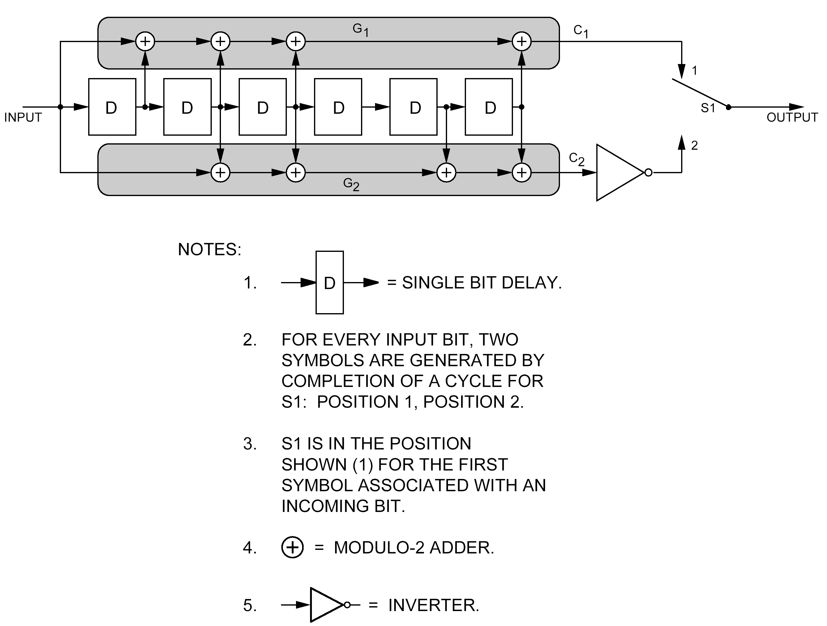 Figure 51: Convolutional encoder block diagram
Punctured convolutional code
The punctured convolutional code shall have the characteristics shown in Table 52.
- 1 A single code rate of 2/3, 3/4, 5/6 or 7/8 is selected when it provides the appropriate level of error correction and symbol rate for a given service or data rate.
- 2 Figure 52 depicts the punctured encoding scheme.
- 3 The punctured convolutional code does not include the symbol inverter associated with G2 in the rate 1/2 code defined above.
The puncturing patterns for each of the punctured convolutional code rates shall be the patterns defined in Table 53.
Table 52: Punctured convolutional code characteristics
|
Characteristic
|
Value
|
|
Nomenclature
|
Punctured convolutional code with maximum-likelihood (Viterbi) decoding.
|
|
Code rate
|
1/2, punctured to 2/3, 3/4, 5/6 or 7/8
|
|
Constraint length
|
7 bits
|
|
Connection vectors
|
G1 = 1111001 (171 octal); G2 = 1011011 (133 octal)
|
|
Symbol inversion
|
None
|
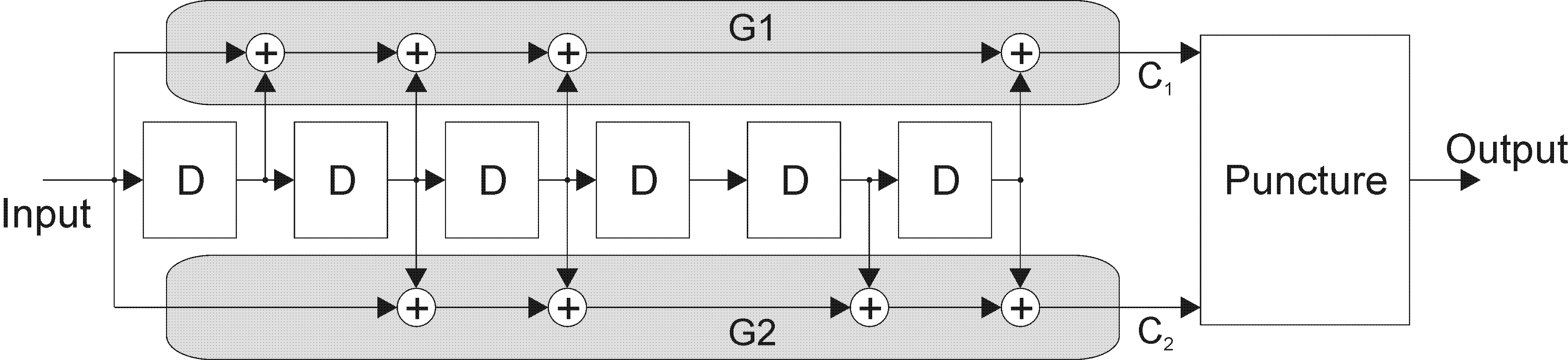 Figure 52: Punctured encoder block diagram
Table 53: Puncture code patterns for convolutional codes
|
Puncturing pattern (a)
|
Code rate
|
Output sequence (b)
|
|
C1: 1 0C2: 1 1
|
2/3
|
C1(1) C2(1) C2(2) ...
|
|
C1: 1 0 1C2: 1 1 0
|
3/4
|
C1(1) C2(1) C2(2) C1(3) ...
|
|
C1: 1 0 1 0 1C2: 1 1 0 1 0
|
5/6
|
C1(1) C2(1) C2(2) C1(3) C2(4) C1(5) ...
|
|
C1: 1 0 0 0 1 0 1C2: 1 1 1 1 0 1 0
|
7/8
|
C1(1) C2(1) C2(2) C2(3) C2(4) C1(5) C2(6) C1(7) ...
|
|
(a) 1 = transmitted symbol0 = non-transmitted symbol
| ||
Reed-Solomon coding
Properties
The Reed-Solomon code defined in this clause provides an excellent forward error correction capability in a burst-noise channel with an extremely low undetected error rate. This means that the decoder can reliably indicate whether it can make the proper corrections or not.
For this reason, when telemetry transfer frames are used, ECSS-E-ST-50-03 does not specify the use of a cyclic redundancy check (CRC) field to validate the frame when this Reed-Solomon Code is used.
The Reed-Solomon error correction and detection presupposes correct frame synchronization. The Reed-Solomon frame validation can only deliver a valid frame if the frame is correctly synchronized. If a frame is not correctly synchronized, then the Reed-Solomon decoder can perform a meaningless error correction of the frame and deliver it as valid.
The reliability of the Reed-Solomon error correction and detection depends on the correct operation of the pseudo-randomization defined in clause 9. If frames are
randomized and then not derandomized, or
not randomized and then derandomized,
then the Reed-Solomon decoder can perform meaningless error correction of a frame and deliver it as valid. In particular, this can happen when the Reed-Solomon interleaving depth, I, is 5.
The Reed-Solomon coding, by itself, cannot guarantee sufficient channel symbol transitions to keep receiver symbol synchronizers in lock. The pseudo-randomizer defined in clause 9 can be used to increase the symbol transition density.
General
For Reed-Solomon coding, the frame synchronization defined in clause 8 shall be used.
The reliability of the Reed-Solomon code depends on proper codeblock synchronization
To provide additional coding gain, the Reed-Solomon code may be concatenated with one of the convolutional codes defined in clause 5.
Used this way, the Reed-Solomon code is the outer code, while the convolutional code is the inner code. Figure 42 shows the order of the codes at the sending and receiving ends.
Specification
Parameters and general characteristics
The Reed-Solomon code shall have the following parameters and general characteristics:
J = 8, where J is the number of bits per R-S symbol.
E = 16, where E is the Reed-Solomon error correction capability, in symbols, within an RS codeword.
J, E, and I (the depth of interleaving) are independent parameters.
n = 2J1 = 255, where n is the number of symbols per RS codeword.
2E is the number of parity check symbols in each codeword. Therefore there are 32 parity check RS symbols in each 255-symbol codeword.
k = n2E, where k is the number of information symbols in each codeword. Therefore there are 223 information RS symbols in each 255-symbol codeword.
The specified Reed-Solomon code is a systematic code and results in a systematic codeblock.
Generator polynomials
The Reed-Solomon code shall have the following field generator polynomial over GF(2):
F(x) = x8 + x7 + x2 + x + 1
The Reed-Solomon code shall have the following code generator polynomial over GF(28), where F() = 0:
![]()
- 1 11 is a primitive element in GF(28).
- 2 For E=16, F(x) and g(x) characterize a (255,223) Reed-Solomon code.
- 3 Each coefficient of the code generator polynomial can be represented as a power of or as a binary polynomial in of degree less than 8, where F() = 0 (i.e. is one of the roots of the field generator polynomial F(x)). The two representations are given in Annex B.
Symbol interleaving depth
The interleaving depth, I, shall take one of the following values:
I = 1, 2, 3, 4, 5 or 8.
- 1 I=1 is equivalent to the absence of interleaving.
- 2 The maximum codeblock length Lmax, measured in RS symbols, depends on the value of I as follows:
Lmax = nI = (2J 1)I = 255I
The interleaving depth on a physical channel shall be fixed for a mission phase.
Symbol interleaving mechanism
Symbol interleaving is accomplished as shown functionally in Figure 61.
The physical implementation of an encoder can differ from this functional description.
Data bits to be encoded into a single Reed-Solomon codeblock enter at the port labelled "IN". Switches S1 and S2 are synchronized together and advance from encoder to encoder in the sequence 1,2, …, I, 1,2, …, I, …, spending one RS symbol time (8 bits) in each position.
One codeblock is formed from kI RS symbols entering "IN". In this functional representation, a space of 2EI RS symbols in duration occurs between each entering set of kI RS information symbols.
Due to the action of S1, each encoder accepts k of these symbols, each symbol spaced I symbols apart (in the original stream). These k symbols are passed directly to the output of each encoder. The synchronized action of S2 reassembles the symbols at the port labelled "OUT" in the same way as they entered at "IN".
Following this, each encoder outputs its 2E check symbols, one symbol at a time, as it is sampled in sequence by S2.
If, for I=5, the original symbol stream is
d. . . dd . . . d . . . d . . . d [2E × 5 ]
then the output is the same sequence with the [2E × 5] filled by the [2E × 5] check symbols as shown below:
p . . . p . . . p . . . p
where
d d . . . d p . . . p
is the RS codeword produced by the ith encoder.
If q virtual fill symbols (see clause 6.3.6) are used in each codeword, then replace k by (kq) in this functional description.
With this method of interleaving, the original kI consecutive information symbols that enter the encoder appear unchanged at the output of the encoder with 2EI RS check symbols appended.
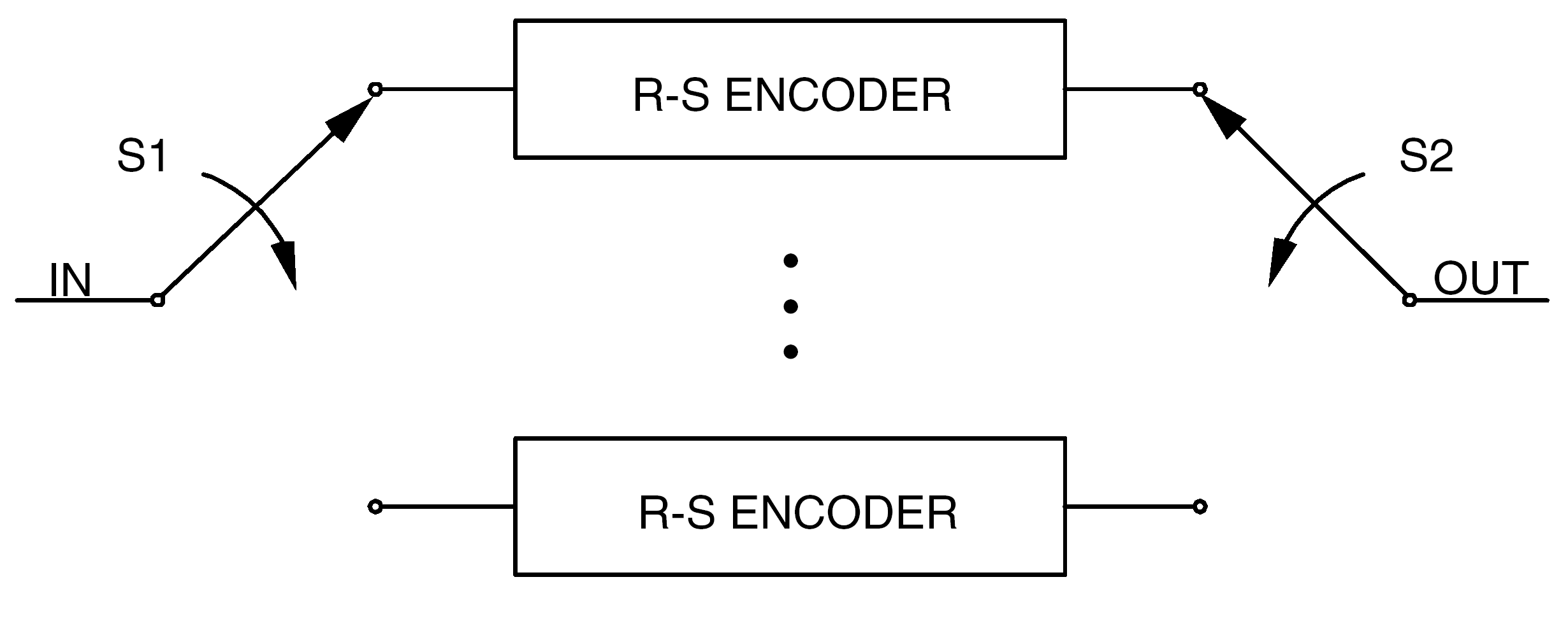 Figure 61: Functional representation of RS interleaving
Reed-Solomon codeblock partitioning
The RS codeblock is partitioned as shown in Figure 62.
The attached sync marker used with RS coding is a 32-bit pattern specified in clause 8 as an aid to synchronization. It precedes the transmitted codeblock. Frame synchronizers are therefore set to expect a marker at every transmitted codeblock + 32 bits.
The telemetry transfer frame is defined in ECSS-E-ST-50-03. When used with RS coding, only specified lengths can be contained within the codeblock’s data space. See Annex C for the maximum lengths, not including the 32-bit attached sync marker.
The Reed-Solomon check symbols consist of the trailing 2EI symbols (2EIJ bits) of the codeblock. For example, when E=16 and I=5, then the length occupied by the check symbols is always 1280 bits.
The transmitted codeblock consists of the telemetry transfer frame (without the 32-bit sync marker) and RS check symbols, which is the received data entity physically fed into the RS decoder. For example, when E=16, k=223 and I=5, the length of the transmitted codeblock is 10 200 bits, unless virtual fill is used. If virtual fill is used, the length of the transmitted codeblock is reduced by the length of the virtual fill.
A description of the use of virtual fill is provided in clause 6.3.6.
The logical codeblock is the logical data entity operated upon by the RS decoder. It can have a different length than the transmitted codeblock because it accounts for the amount of virtual fill that was introduced. For example, when E=16, k=223 and I=5, the logical codeblock always appears to be exactly 10 200 bits in length.
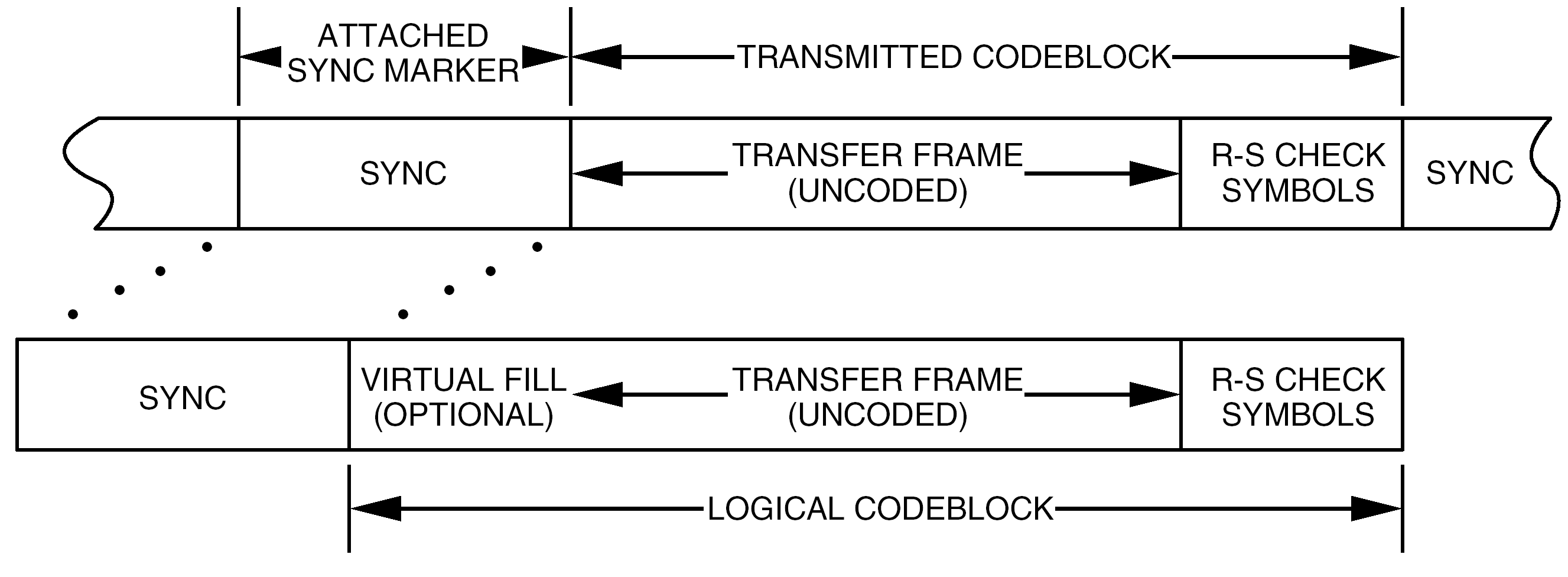 Figure 62: Reed-Solomon codeblock partitioning
Shortened codeblock length
Overview
In a systematic block code, a codeword can be divided into an information part and a parity (check) part. If the information part is k symbols long, a shortened code is created by taking only s (s < k) information symbols as input, appending a fixed string of length ks and then encoding in the normal way. This fixed string is called virtual fill.
Since the fill is a predetermined sequence of symbols, it is not transmitted over the channel, resulting in a shortened codeblock length. Thus the length of the transmitted codeblock is reduced by the length of the virtual fill.
At the receiving end, the decoder appends the same fill sequence before decoding. The transmitted codeblock together with the virtual fill forms the logical codeblock. Figure 62 illustrates the transmitted codeblock and the logical codeblock.
Shortening the transmitted codeblock length in this way changes the overall performance to a degree dependent on the amount of virtual fill used. Since it incorporates no virtual fill, the maximum codeblock length provides full performance.
General
A shortened codeblock length may be used to accommodate frame lengths smaller than the maximum.
Virtual fill shall be inserted only in integer multiples of 8I bits.
The virtual fill shall not change in length during a mission phase.
Virtual fill shall be inserted only at the beginning of the codeblock (i.e. after the attached sync marker but before the beginning of the transmitted codeblock).
Virtual fill shall not be transmitted.
Virtual fill is used to logically complete the codeblock.
Virtual fill shall consist of all zeros.
If virtual fill is used, the resulting rate of codeblocks per unit time shall be calculated to ensure that the maximum operating speed of the decoder is not exceeded.
As virtual fill in a codeblock is increased (at a specific bit rate), the number of codeblocks per unit time increases.
Use of virtual fill
Since the Reed-Solomon code is a block code, the decoder always operates on a full block basis. To achieve a full codeblock, virtual fill is added to make up the difference between the shortened block and the maximum codeblock length.
Successful decoding depends on the configuration of the encoder and decoder to insert the correct length of virtual fill. Otherwise, the decoding cannot be carried out properly.
When an encoder (initially cleared at the start of a block) receives kIQ symbols representing information (where Q, representing fill, is a multiple of I, and is less than kI), 2EI check symbols are computed over kI symbols, of which the leading Q symbols are treated as all-zero symbols. A (nIQ, kIQ) shortened codeblock results where the leading Q symbols (all zeros) are neither entered into the encoder nor transmitted.
Dual basis symbol representation and ordering
Each 8-bit Reed-Solomon symbol is an element of the finite field GF(256). Since GF(256) is a vector space of dimension 8 over the binary field GF(2), the actual 8-bit representation of a symbol is a function of the particular basis that is chosen.
One basis for GF(256) over GF(2) is the set ( 1, 1, 2, . . ., 7 ). This means that any element of GF(256) has a representation of the form
u77 + u66 + . . . + u11 + u00
where each ui is either a 0 or a 1.
Another basis over GF(2) is the set ( 1, 1, 2, . . ., 7) where = 117. To this basis there exists a so-called "dual basis" (l0, l1, . . ., l7). This has the property
|
Tr(lij ) = |
1, if i = j
|
|
0, otherwise
|
for each j = 0, 1, . . ., 7. The function Tr(z), called the "trace", is defined by
Tr(z) =
for each element z of GF(256). Each Reed-Solomon symbol can also be represented as
z0l0 + z1l1 + . . . + z7l7
where each zi is either a 0 or a 1.
The representation used in this Standard is the dual basis 8-bit string z0, z1, . . ., z7, transmitted in that order (i.e. with z0 first). The relationship between the two representations is given by the two equations
[z0, . . ., z7] = [u7, . . ., u0]
and
[u7, . . ., u0] = [z0, . . ., z7]
Further information relating the dual basis (Berlekamp) and conventional representations is given in Annex A. Also included is a scheme for transforming the symbols generated in a conventional encoder to the symbol representation used by this Standard.
Synchronization
Codeblock synchronization of the Reed-Solomon decoder is achieved by synchronization of the attached sync marker associated with each codeblock (see clause 8.)
Ambiguity resolution
The ambiguity between true and complemented data shall be resolved so that only true data is provided to the Reed-Solomon decoder.
Data in NRZL form is normally resolved using the 32-bit attached sync marker. NRZ-M data is self-resolving.
Reed-Solomon with E=8
Introduction
There is a Reed-Solomon code which has E=8 and which otherwise follows the specification in clauses 6.3.1 to 6.3.9. This alternative code has lower overhead with reduced performance and can correct 8 Reed-Solomon symbols per codeword.
For E=8:
2E, the number of parity check symbols in each codeword, is 16.
k, the number of information symbols in each codeword, is 239.
J = 8 and n = 255 as for the E=16 code in clause 6.3.1.
For E=8, the generator polynomials F(x) and g(x) specified in clause 6.3.2 characterize a (255,239) Reed-Solomon code.
In this Standard, the use is limited to links which have 4-dimensional 8PSK trellis-coded modulation (4D-8PSK-TCM). When Reed-Solomon with E=8 is used, then the requirements in clause 6.4.2 apply.
General
The Reed-Solomon code with E=8 shall only be used if the modulation scheme is 4D-8PSK-TCM.
The modulation scheme 4D-8PSK-TCM is defined in ECSS-E-ST-05.
The Reed-Solomon code with E=8 shall not be concatenated with one of the convolutional codes defined in clause 5.
For the Reed-Solomon code with E=8, the interleaving depth, I, shall take the value 8.
The error correction and detection capability of Reed-Solomon code with E=8 is limited and the output of a 4D-8PSK-TCM decoder is liable to burst errors. An interleaving depth of I=8 improves the combined error correction and detection capability of the Reed-Solomon code with 4D-8PSK-TCM.
Turbo coding
Properties
Turbo codes are binary block codes with large code blocks (hundreds or thousands of bits). They are systematic and inherently non-transparent. Phase ambiguities are resolved using frame markers, which are used for codeblock synchronization.
Turbo codes can be used to obtain even greater coding gain than those provided by concatenated coding systems.
Turbo coding, by itself, cannot guarantee sufficient bit transitions to keep receiver symbol synchronizers in lock. The pseudo-randomizer defined in clause 9 can be used to increase the symbol transition density.
Further details on the operational environment and performance of the specified turbo codes can be found in CCSDS 130.1-G-1.
While providing significant coding gain, turbo codes can still leave some residual errors in the decoded output. For this reason, when telemetry transfer frames are used, reference ECSS-E-ST-50-03 specifies that a cyclic redundancy check (CRC) field be used to validate the frame. Similarly, the CRC is used for the AOS transfer frames defined in CCSDS 732.0-B-2.
Implementers are informed that a wide class of turbo codes is covered by patent rights (see Annex H).
General
For turbo coding, the frame synchronization defined in clause 8 shall be used.
Differential encoding (i.e. NRZ-M signalling) after the turbo encoder should not be used.
Soft decoding implies the use of differential detection with considerable loss of performance. Differential encoding before the turbo encoder cannot be used because the turbo codes specified in this Standard are non-transparent. This implies that phase ambiguities are detected and resolved by the frame synchronizer.
Specification
General
A turbo encoder is a combination of two simple encoders. The input is a frame of k information bits. The two component encoders generate parity symbols from two simple recursive convolutional codes, each with a small number of states. The information bits are also sent uncoded. A key feature of turbo codes is an interleaver which permutes, bit-wise, the original k information bits before input to the second encoder.
The turbo code defined in this Standard is a systematic code.
Parameters and general characteristics
The turbo code shall have the following parameters and general characteristics:
- The code type is a systematic parallel concatenated turbo code.
- There are 2 component codes, and there is also an uncoded component to make the code systematic.
- The component codes are recursive convolutional codes.
- Each convolutional component code has 16 states.
The nominal code rate, r, shall be selected from one of the following values:
r = 1/2 or 1/4.
Due to trellis termination symbols (see clause 7.3.6), the true code rates (defined as the ratios of the information block lengths to the codeblock lengths in Table 72) are slightly smaller than the nominal code rates. In this Standard, code rate always refers to the nominal code rates, r = 1/2 or 1/4.
The information block length k shall be selected from one of the values specified in Table 71.
- 1 The lengths are chosen for compatibility with the corresponding Reed-Solomon interleaving depths, also shown in Table 71.
- 2 The corresponding codeblock lengths in bits, n=(k+4)/r, for the specified code rates are shown in Table 72.
- 3 An additional information block length of 16384 bits (2048 octets) is currently under study.
If the information block length of 1784 bits is used, the resulting rate of codeblocks per unit time shall be calculated to ensure that the maximum operating speed of the decoder is not exceeded.
A short block length can result in a high number of codeblocks per unit time. The decoding latency and performance are considered in this case.
Table 71: Specified information block lengths
|
Information block length k, bits
|
Corresponding Reed-Solomon interleaving depth I
|
|
1784 (=223 × 1 octets)
|
1
|
|
3568 (=223 × 2 octets)
|
2
|
|
7136 (=223 × 4 octets)
|
4
|
|
8920 (=223 × 5 octets)
|
5
|
Table 72: Codeblock lengths (measured in bits)
|
Information block length k, bits
|
Codeblock length n, bits
| |
|
rate 1/2
|
rate 1/4
| |
|
1784
|
3576
|
7152
|
|
3568
|
7144
|
14288
|
|
7136
|
14280
|
28560
|
|
8920
|
17848
|
35696
|
Turbo code permutation
The interleaver is a fundamental component of the turbo encoding and decoding process. The interleaver for turbo codes is a fixed bit-by-bit permutation of the entire block of data. Unlike the symbol-by-symbol rectangular interleaver used with Reed-Solomon codes, the turbo code permutation scrambles individual bits and resembles a randomly selected permutation in its lack of apparent orderliness.
The permutation for each specified block length k is given by a specific reordering of the integers 1, 2, . . ., k as generated by the following algorithm.
First, k is expressed as k=k1k2. The parameters k1 and k2 for the specified block sizes are given in Table 73.
Next, the following operations are performed for s=1 to s=k to obtain permutation numbers (s). In the equations below, x denotes the largest integer less than or equal to x, and pq denotes one of the following eight prime integers:
p1= 31; p2= 37; p3= 43; p4= 47; p5= 53; p6= 59; p7= 61; p8= 67
|
m |
= |
(s – 1) mod 2 |
|
i |
= |
|
|
j |
= |
– i k2 |
|
t |
= |
(19i + 1) mod |
|
q |
= |
t mod 8 + 1 |
|
c |
= |
(pq j + 21m) mod k2 |
|
(s) |
= |
2(t + c + 1) – m |
The interpretation of the permutation numbers is such that the sth bit read out on line "in b" in Figure 72 is the (s)th bit of the input information block, as shown in Figure 71.
Table 73: Parameters k1 and k2 for specified information block lengths
|
Information block length (bits)
|
k1
|
k2
|
|
1784
|
8
|
223
|
|
3568
|
8
|
223 × 2
|
|
7136
|
8
|
223 × 4
|
|
8920
|
8
|
223 × 5
|
 Figure 71: Interpretation of permutation
Backward and forward connection vectors
The backward connection vector for both component codes and all code rates is:
G0 = 10011.The forward connection vectors are shown in Table 74.
Table 74: Forward connection vectors
|
Rate
|
Components
|
Vectors
|
Puncturing
|
|
1/2
|
both codes
|
G1 = 11011
|
every other symbol from each component code
|
|
1/4
|
1st component code
|
G2 = 10101
|
none
|
|
2nd component code
|
G1 = 11011
|
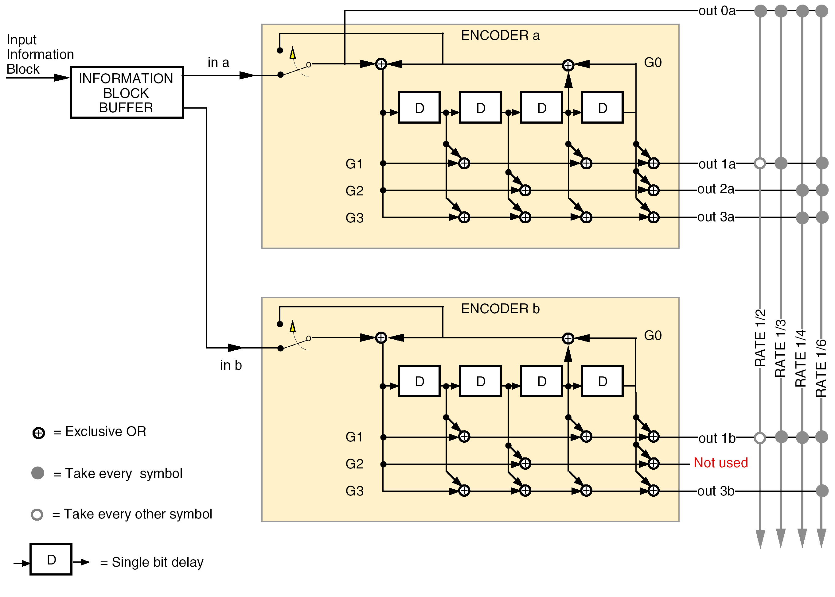 Figure 72: Turbo encoder block diagram
Turbo encoder block
In Figure 72 each input frame of k information bits is held in a frame buffer, and the bits in the buffer are read out in two different orders for the two component encoders. The first component encoder (a) operates on the bits in unpermuted order ("in a"), while the second component encoder (b) receives the same bits permuted by the interleaver ("in b"). The read-out addressing for "in a" is a simple counter, while the addressing for "in b" is specified by the turbo code permutation described in clause 7.3.3.
The component encoders are recursive convolutional encoders realized by feedback shift registers as shown in Figure 72. The circuits shown in this figure implement the backward connection vector, G0, and the forward connection vectors, G1, G2, G3, specified in Table 74.
The block diagram also shows the encoding for rate 1/3 and rate 1/6 codes which are not specified in this Standard.
A key difference between these convolutional component encoders and the standalone convolutional encoder specified in clause 5 is their recursiveness. In the figure this is indicated by the signal (corresponding to the backward connection vector G0) fed back into the leftmost adder of each component encoder.
Turbo codeblock specification
Both component encoders in Figure 72 are initialized with zeros in all registers, and both are run for a total of k+4 bit times, producing an output codeblock of (k+4)/r encoded symbols, where r is the nominal code rate.
For the first k bit times, the input switches are in the lower position (as indicated in the figure) to receive input data. For the final 4 bit times, these switches move to the upper position to receive feedback from the shift registers.
This feedback cancels the same feedback sent (unswitched) to the leftmost adder and causes all four registers to become filled with zeros after the final 4 bit times. Filling the registers with zeros is called terminating the trellis.
During trellis termination the encoder continues to output non-zero encoded symbols. In particular, the "systematic uncoded" output (line "out 0a" in the figure) includes an extra 4 bits from the feedback line in addition to the k information bits.
In Figure 72, the encoded symbols are multiplexed from top-to-bottom along the output line for the selected code rate to form the turbo codeblock.
For the rate 1/2 code, the output sequence is (out 0a, out 1a, out 0a, out 1b), repeated (k+4)/2 times. This pattern implies that puncturing is applied first to out 1b, second to out 1a, and so forth.
For the rate 1/4 code, the output sequence is (out 0a, out 2a, out 3a, out 1b). This sequence is repeated for (k+4) bit times.
The turbo codeblocks constructed from these output sequences are depicted in Figure 73 for the two nominal code rates.
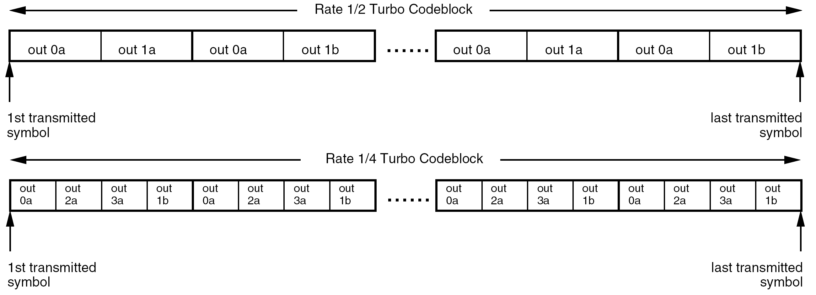 Figure 73: Turbo codeblocks for code rates 1/2 and 1/4
Turbo codeblock synchronization
Codeblock synchronization of the turbo decoder is achieved by synchronization of an attached sync marker (ASM) associated with each turbo codeblock. The ASM is a bit pattern specified in clause 8. The ASM precedes the turbo codeblock.
Frame synchronizers are set to expect a marker at a recurrence interval equal to the length of the ASM plus that of the turbo codeblock.
A diagram of a turbo codeblock with attached sync marker is shown in Figure 74.
The length of the turbo codeblock is inversely proportional to the nominal code rate r.
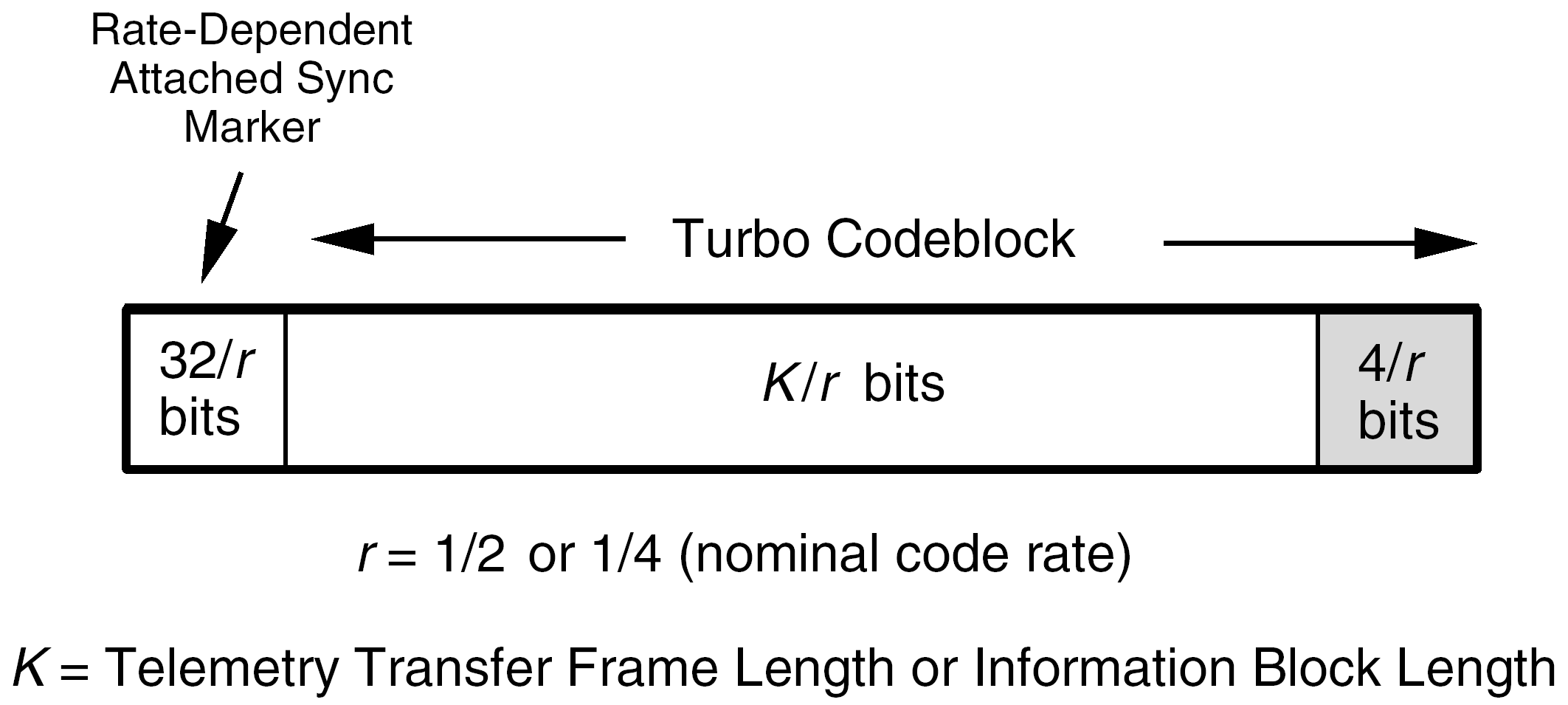 Figure 74: Turbo codeblock with attached sync marker
Frame synchronization
Introduction
Frame or codeblock synchronization is an essential part of the processing of the telemetry data stream. The following actions depend on accurate synchronization:
Correct decoding of Reed-Solomon codeblocks and turbo codeblocks.
Processing of the transfer frames.
Synchronization of the pseudo-random generator, if used (see clause 9).
It is also useful in assisting the node synchronization process of the Viterbi decoder for the convolutional code.
The attached sync marker (ASM)
Overview
Synchronization of the Reed-Solomon or turbo codeblock (or transfer frame, if the telemetry channel is not Reed-Solomon coded or turbo coded) is achieved by using a stream of fixed-length codeblocks (or transfer frames) with an attached sync marker (ASM) between them. The data unit that consists of the ASM and the Reed-Solomon or turbo codeblock or transfer frame is called the channel access data unit (CADU), as shown in Figure 81.
 Figure 81: Format of channel access data unit (CADU)
Figure 41 and Figure 42 show how synchronization is combined with the different coding options.
Synchronization is acquired at the receiving end by recognizing the specific bit pattern of the ASM in the telemetry channel data stream; synchronization is then customarily confirmed by making further checks.
Encoder side
If the telemetry channel is uncoded, Reed-Solomon coded, or turbo coded, the code symbols comprising the ASM shall be attached directly to the encoder output without being encoded by the Reed-Solomon or turbo code.
If an inner convolutional code is used in conjunction with an outer Reed-Solomon code, the ASM shall be encoded by the inner code but not by the outer code.
Decoder side
For a concatenated Reed-Solomon and convolutional coding system, the ASM may be acquired either in the channel symbol domain (i.e. before any decoding) or in the domain of bits decoded by the inner code (i.e. the code symbol domain of the Reed-Solomon code).
For a turbo coding system, the ASM shall be acquired in the channel symbol domain (i.e. the code symbol domain of the turbo code).
ASM bit patterns
The ASM for telemetry data that is not turbo coded shall consist of a 32-bit (4-octet) marker with the pattern shown in Figure 82.
The ASM for data that is turbo coded with nominal code rate r = 1/2 or 1/4 shall consist of a 32/r-bit (4/r-octet) marker with bit patterns shown in Figure 83 and Figure 84.
Table 81 shows the ASM bit patterns in hexadecimal notation.
 Figure 82 ASM bit pattern for non-turbo-coded data
 Figure 83: ASM bit pattern for rate 1/2 turbo-coded data
 Figure 84: ASM bit pattern for rate 1/4 turbo-coded data
Table 81: ASM bit patterns in hexadecimal notation
|
Data type
|
ASM in hexadecimal notation
|
|
non-turbo-coded data
|
1ACFFC1D
|
|
rate-1/2 turbo coded data
|
034776C7 272895B0
|
|
rate-1/4 turbo coded data
|
034776C7 272895B0 FCB88938 D8D76A4F
|
Location of ASM
The ASM shall be attached to, and immediately precede, the Reed-Solomon or turbo codeblock, or the transfer frame if the telemetry channel is not Reed-Solomon or turbo coded.
The ASM for one codeblock (or transfer frame) shall immediately follow the end of the preceding codeblock (or transfer frame).
This implies that there are no intervening bits (i.e. data or fill) preceding the ASM.
Relationship of ASM to Reed-Solomon and turbo codeblocks
The ASM shall not be presented to the input of the Reed-Solomon encoder or decoder.
- 1 This prevents the encoder from routinely regenerating a second, identical marker in the check symbol field under certain repeating data-dependent conditions (e.g. a test pattern of 01010101010…) which can cause synchronization difficulties at the receiving end.
- 2 The ASM is not a part of the encoded data space of the Reed-Solomon codeblock.
- 3 The relationship between the ASM, Reed-Solomon codeblock, and transfer frame is illustrated in Figure 62.
The ASM shall not be presented to the input of the turbo encoder or decoder.
The ASM is directly attached to the turbo codeblock as shown in Figure 74.
ASM for embedded data stream
Overview
For legacy reasons, this clause provides a description of the requirements which apply if an embedded data stream uses a different ASM pattern.
The embedded data stream described in this clause is not used for turbo coded transfer frames.
For example, a stream of transfer frames with ASMs can be recorded for later transmission. If the stream is played back in the forward direction and embedded in the data fields of a stream of real-time transfer frames, then the embedded ASM can cause synchronization problems at the receiving end. To avoid this, a different ASM pattern is used for the embedded ASM.
Embedded ASM
The embedded ASM shall not be used with turbo coded transfer frames.
If a stream of transfer frames is recorded for insertion in the forward direction into the data fields of the transfer frames of a real-time telemetry channel, then the recorded stream shall use the embedded ASM.
The embedded ASM shall consist of a 32-bit (4-octet) marker with the pattern shown in Figure 85.
This pattern is represented in hexadecimal notation as:
352EF853
 Figure 85: Embedded ASM bit pattern
Pseudo-randomizer
General
Overview
In order to maintain bit (or symbol) synchronization with the received telemetry signal, the data capture system depends on the incoming signal having a minimum bit transition density.
If the data stream is sufficiently random then the minimum bit transition density is achieved. The pseudo-randomizer defined in this clause is used to ensure sufficient randomness.
- 1 ECSS-E-ST-50-05 specifies values for the minimum transition density. System designer are advised to consult ECSS-E-ST-50-05 for the requirements on the use of the pseudo-randomizer on the telemetry link.
- 2 Problems with telemetry links have been encountered because this pseudo-randomizer was not used and sufficient randomness was not ensured by other means and properly verified.
Application
The presence or absence of pseudo-randomization shall be fixed for a physical channel.
The presence or absence of pseudo-randomization shall be managed, that is, its presence or absence is not signalled in the telemetry but shall be known, a priori, by the receiving system.
Pseudo-randomizer description
The method for pseudo-randomization is to exclusive-OR each bit of the codeblock or transfer frame with a standard pseudo-random sequence.
At the sending end, the method is applied to the codeblock or transfer frame after turbo encoding or R-S encoding (if either is used), but before convolutional encoding (if used).
Figure 91 shows the pseudo-randomizer configuration at the sending end. Figure 41 and Figure 42 show how pseudo-randomization is combined with synchronization and with the different coding options.
At the receiving end, the method is applied to derandomize the data after convolutional decoding (if used) and codeblock synchronization but before Reed-Solomon decoding or turbo decoding (if either is used).
Derandomization consists of either:
exclusive-ORing the pseudo-random sequence with the received bits of a transfer frame or a Reed-Solomon codeblock, or
inverting (or not inverting), according to the pseudo-randomizer bit pattern, the demodulator output of a turbo codeblock.
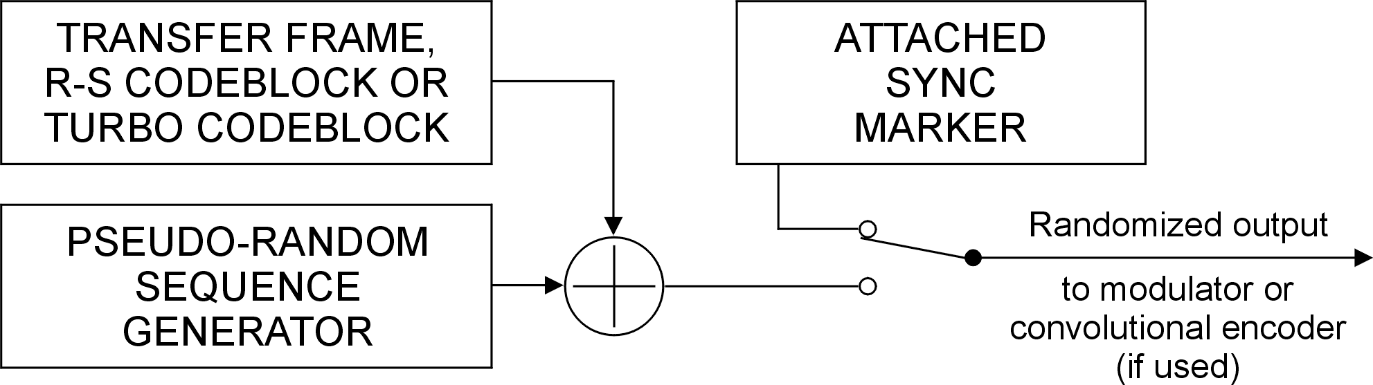 Figure 91: Pseudo-randomizer configuration
Synchronization and application of pseudo-randomizer
Overview
The attached sync marker (ASM) is already optimally configured for synchronization purposes and it is therefore used for synchronizing the pseudo-randomizer.
At the sending end, the pseudo-random sequence is applied starting with the first bit of the codeblock or transfer frame. At the receiving end, after locating the ASM in the received data stream, the pseudo-random sequence is applied to the data bits immediately following the ASM.
Application
The same pseudo-random sequence shall be used at the sending end and at the receiving end.
At the sending end, the codeblock or transfer frame shall be randomized as follows:
- Exclusive-ORing the first bit of the codeblock or transfer frame with the first bit of the pseudo-random sequence.
- Exclusive-ORing the second bit of the codeblock or transfer frame with the second bit of the pseudo-random sequence.
- Continuing until each bit of the codeblock or transfer frame is exclusive-ORed with the corresponding bit of the pseudo-random sequence. At the receiving end, the original codeblock or transfer frame shall be reconstructed as follows:
- Exclusive-ORing the first bit following the ASM with the first bit of the pseudo-random sequence.
- Exclusive-ORing the second bit following the ASM with the second bit of the pseudo-random sequence.
- Continuing until each bit of the randomized transfer frame is exclusive-ORed with the corresponding bit of the pseudo-random sequence. The pseudo-random sequence shall not be exclusive-ORed with the ASM.
Sequence specification
The pseudo-random sequence shall be generated using the following polynomial:
Equation h(x) = x8 + x7 + x5 + x3 + 1
- 1 Figure 92 contains an example of a pseudo-random sequence generator based on the specified polynomial.
- 2 Once initialized, a pseudo-randomizer using the specified polynomial generates a binary sequence that is periodic and repeats after 28-1 = 255 bits.
- 3 Except for high data rate telemetry (typically above 2 megasymbols/second), the period of the pseudo-random binary sequence based on the specified polynomial is compatible with the spectral lines and power flux density requirements in ECSS-E-ST-50-05. At the time of issue of this Standard, within ECSS, no randomization scheme has been agreed upon for high data rate telemetry. The frequency coordinator can provide advice in this case.
The sequence generator shall be initialized to the all-ones state at the start of each codeblock or transfer frame. - 1 The pseudo-random sequence output from the generator begins at the first bit of the codeblock or transfer frame, continuing until the end of the codeblock or transfer frame.
- 2 The first 40 bits of the pseudo-random sequence from the generator are: 1111 1111 0100 1000 0000 1110 1100 0000 1001 1010 . . . . The leftmost bit is the first bit of the sequence to be exclusive-ORed with the first bit of the codeblock or transfer frame; the second bit of the sequence is exclusive-ORed with the second bit of the codeblock or transfer frame, and so on.
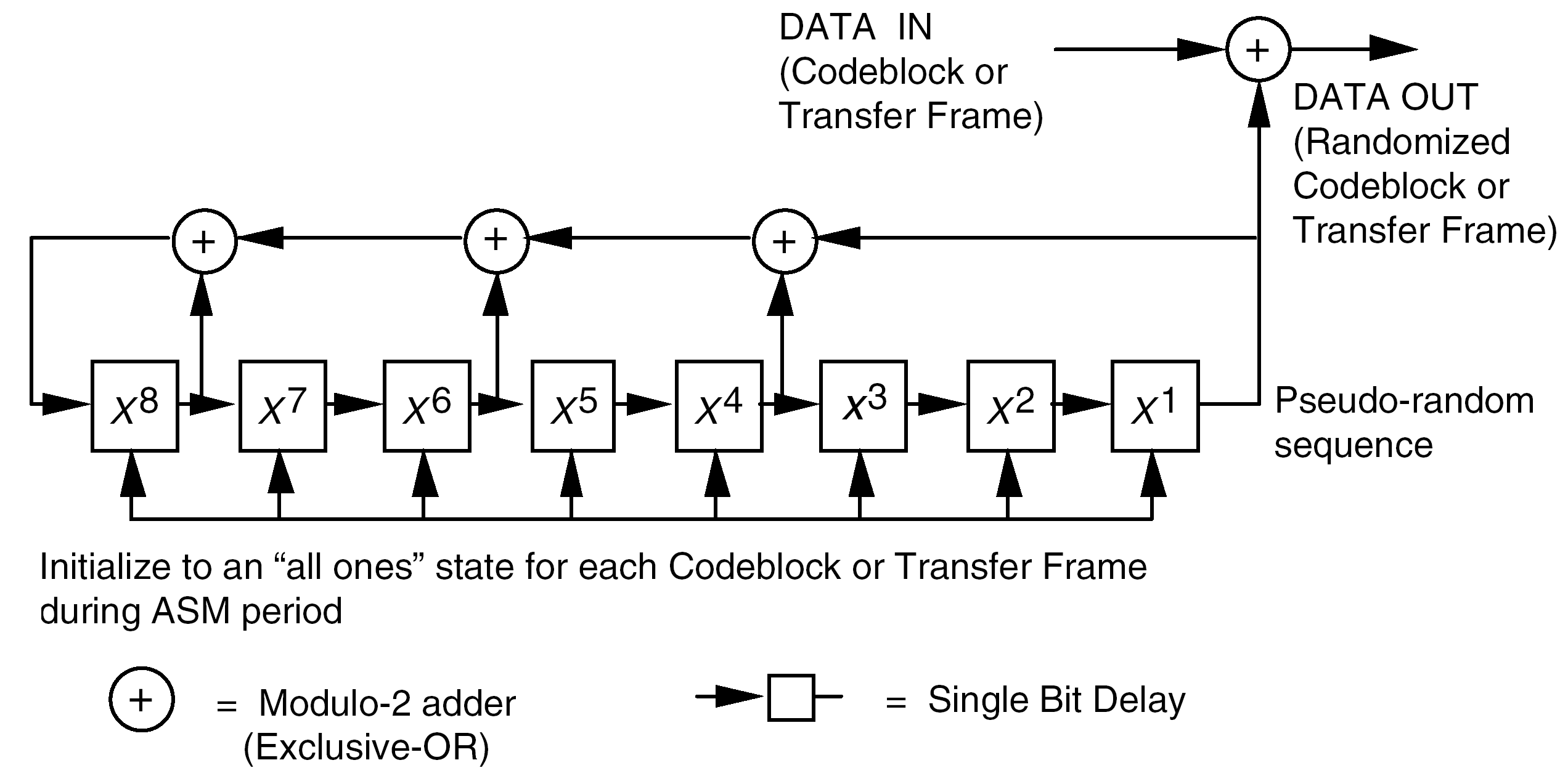 Figure 92: Pseudo-randomizer logic diagram
ANNEX(informative)Transformation between Berlekampand conventional representations
Overview
This annex provides information for users of the Reed-Solomon to transform between the Berlekamp (dual basis) and conventional representations. In addition, it shows where transformations are made so that a conventional encoder can produce the dual basis representation on which this Standard is based.
Transformation
General
Referring to Figure A-1, it can be seen that information symbols I entering and check symbols C emanating from the Berlekamp RS encoder are interpreted as
[z0, z1, ... , z7]
where the components zi are coefficients of li, respectively:
z0l0 + z1l1 + ... + z7l7
Information symbols I' entering and check symbols C' emanating from the conventional RS encoder are interpreted as
[u7, u6, ... , u0]
where the components uj are coefficients of j, respectively:
u77 + u66 + ... + u0
When using a conventional RS encoder, a pre- and post-transformation is applied.
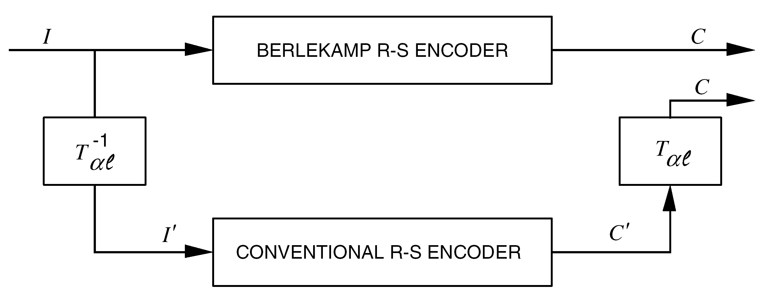 Figure: Transformational equivalence
Conventional and Berlekamp types of (255,k) Reed-Solomon encoders are assumed to have the same self-reciprocal generator polynomial whose coefficients appear in clause 6.3.2.
The representation of symbols associated with the conventional encoder are the polynomials in appearing in Table A-1. Corresponding to each polynomial in is the representation in the dual basis of symbols associated with the Berlekamp type encoder.
Given that:
i = u77 + u66 + ... + u0
where 0 i < 255 (and * denotes the zero polynomial, u7, u6, ... = 0, 0, ...), the corresponding element is:
z = z0l0 + z1l1 + ... + z7l7
where
[z0, z1, ..., z7] = [u7, u6, ..., u0] Tl
and
Tl =
Row 1, row 2, ... , and row 8 in Tl are representations in the dual basis of 7 (10 ... 0), 6 (010 ... 0), ... , and 0 (00 ... 01), respectively.
The inverse of Tl is:
T=
Row 1, row 2, ... , and row 8 in T are polynomials in corresponding to l0 (10 ... 0), l1 (010 ... 0), ... , and l7 (00, ... 01), respectively. Thus,
[z0, z1, ..., z7] T= [u7, u6, ..., u0]#### Example 1
Given information symbol I,
[z0, z1, ..., z7] = 10111001
then
T
[10111001] = [u7, u6, ..., u0] = 00101010 = I'
Note that the arithmetic operations are reduced modulo 2.
Also,
[z0, z1, ..., z7] = 10111001
and
[u7, u6, ..., u0] = 00101010 (213)
are corresponding entries in Figure A-1.
Example 2:
Given the check symbol C',
[u7, u6, ..., u0] = 01011001 (152)
Then,
Tl
[01011001] = [z0, z1, ..., z7] = 11101000 = C
Table: Equivalence of representations (Part 1 of 4)
|
Power
|
Polynomial
|
l01234567
|
Power
|
Polynomial
|
l01234567
|
|
*
|
00000000
|
00000000
|
31
|
11001101
|
01111010
|
|
0
|
00000001
|
01111011
|
32
|
00011101
|
10011110
|
|
1
|
00000010
|
10101111
|
33
|
00111010
|
00111111
|
|
2
|
00000100
|
10011001
|
34
|
01110100
|
00011100
|
|
3
|
00001000
|
11111010
|
35
|
11101000
|
01110100
|
|
4
|
00010000
|
10000110
|
36
|
01010111
|
00100100
|
|
5
|
00100000
|
11101100
|
37
|
10101110
|
10101101
|
|
6
|
01000000
|
11101111
|
38
|
11011011
|
11001010
|
|
7
|
10000000
|
10001101
|
39
|
00110001
|
00010001
|
|
8
|
10000111
|
11000000
|
40
|
01100010
|
10101100
|
|
9
|
10001001
|
00001100
|
41
|
11000100
|
11111011
|
|
10
|
10010101
|
11101001
|
42
|
00001111
|
10110111
|
|
11
|
10101101
|
01111001
|
43
|
00011110
|
01001010
|
|
12
|
11011101
|
11111100
|
44
|
00111100
|
00001001
|
|
13
|
00111101
|
01110010
|
45
|
01111000
|
01111111
|
|
14
|
01111010
|
11010000
|
(b)46
|
11110000
|
00001000
|
|
15
|
11110100
|
10010001
|
47
|
01100111
|
01001110
|
|
16
|
01101111
|
10110100
|
48
|
11001110
|
10101110
|
|
17
|
11011110
|
00101000
|
49
|
00011011
|
10101000
|
|
18
|
00111011
|
01000100
|
50
|
00110110
|
01011100
|
|
19
|
01110110
|
10110011
|
51
|
01101100
|
01100000
|
|
20
|
11101100
|
11101101
|
52
|
11011000
|
00011110
|
|
21
|
01011111
|
11011110
|
53
|
00110111
|
00100111
|
|
22
|
10111110
|
00101011
|
54
|
01101110
|
11001111
|
|
23
|
11111011
|
00100110
|
55
|
11011100
|
10000111
|
|
24
|
01110001
|
11111110
|
56
|
00111111
|
11011101
|
|
25
|
11100010
|
00100001
|
57
|
01111110
|
01001001
|
|
26
|
01000011
|
00111011
|
58
|
11111100
|
01101011
|
|
27
|
10000110
|
10111011
|
59
|
01111111
|
00110010
|
|
28
|
10001011
|
10100011
|
60
|
11111110
|
11000100
|
|
29
|
10010001
|
01110000
|
61
|
01111011
|
10101011
|
|
30
|
10100101
|
10000011
|
62
|
11110110
|
00111110
|
|
(a) Coefficients of the Polynomial in alpha column are listed in descending powers of , starting with 7.
| |||||
|
(b) The underlined entries correspond to values with exactly one non-zero element and match a row in the matrix.
| |||||
Table A-1: Equivalence of representations (Part 2 of 4)
|
Power
|
Polynomial
|
l01234567
|
Power
|
Polynomial
|
l01234567
|
|
63
|
01101011
|
00101101
|
95
|
10111010
|
10110010
|
|
64
|
11010110
|
11010010
|
96
|
11110011
|
11011100
|
|
65
|
00101011
|
11000010
|
97
|
01100001
|
01111000
|
|
66
|
01010110
|
01011111
|
98
|
11000010
|
11001101
|
|
67
|
10101100
|
00000010
|
99
|
00000011
|
11010100
|
|
68
|
11011111
|
01010011
|
100
|
00000110
|
00110110
|
|
69
|
00111001
|
11101011
|
101
|
00001100
|
01100011
|
|
70
|
01110010
|
00101010
|
102
|
00011000
|
01111100
|
|
71
|
11100100
|
00010111
|
103
|
00110000
|
01101010
|
|
72
|
01001111
|
01011000
|
104
|
01100000
|
00000011
|
|
73
|
10011110
|
11000111
|
105
|
11000000
|
01100010
|
|
74
|
10111011
|
11001001
|
106
|
00000111
|
01001101
|
|
75
|
11110001
|
01110011
|
107
|
00001110
|
11001100
|
|
76
|
01100101
|
11100001
|
108
|
00011100
|
11100101
|
|
77
|
11001010
|
00110111
|
109
|
00111000
|
10010000
|
|
78
|
00010011
|
01010010
|
110
|
01110000
|
10000101
|
|
79
|
00100110
|
11011010
|
111
|
11100000
|
10001110
|
|
80
|
01001100
|
10001100
|
112
|
01000111
|
10100010
|
|
81
|
10011000
|
11110001
|
113
|
10001110
|
01000001
|
|
82
|
10110111
|
10101010
|
114
|
10011011
|
00100101
|
|
83
|
11101001
|
00001111
|
115
|
10110001
|
10011100
|
|
84
|
01010101
|
10001011
|
116
|
11100101
|
01101100
|
|
85
|
10101010
|
00110100
|
117
|
01001101
|
11110111
|
|
86
|
11010011
|
00110000
|
118
|
10011010
|
01011110
|
|
87
|
00100001
|
10010111
|
119
|
10110011
|
00110011
|
|
88
|
01000010
|
01000000
|
120
|
11100001
|
11110101
|
|
89
|
10000100
|
00010100
|
121
|
01000101
|
00001101
|
|
90
|
10001111
|
00111010
|
122
|
10001010
|
11011000
|
|
91
|
10011001
|
10001010
|
123
|
10010011
|
11011111
|
|
92
|
10110101
|
00000101
|
124
|
10100001
|
00011010
|
|
93
|
11101101
|
10010110
|
125
|
11000101
|
10000000
|
|
94
|
01011101
|
01110001
|
126
|
00001101
|
00011000
|
Table A-1: Equivalence of representations (Part 3 of 4)
|
Power
|
Polynomial
|
l01234567
|
Power
|
Polynomial
|
l01234567
|
|
127
|
00011010
|
11010011
|
159
|
10000101
|
01101111
|
|
128
|
00110100
|
11110011
|
160
|
10001101
|
10010101
|
|
129
|
01101000
|
11111001
|
161
|
10011101
|
00010011
|
|
130
|
11010000
|
11100100
|
162
|
10111101
|
11111111
|
|
131
|
00100111
|
10100001
|
163
|
11111101
|
00010000
|
|
132
|
01001110
|
00100011
|
164
|
01111101
|
10011101
|
|
133
|
10011100
|
01101000
|
165
|
11111010
|
01011101
|
|
134
|
10111111
|
01010000
|
166
|
01110011
|
01010001
|
|
135
|
11111001
|
10001001
|
167
|
11100110
|
10111000
|
|
136
|
01110101
|
01100111
|
168
|
01001011
|
11000001
|
|
137
|
11101010
|
11011011
|
169
|
10010110
|
00111101
|
|
138
|
01010011
|
10111101
|
170
|
10101011
|
01001111
|
|
139
|
10100110
|
01010111
|
171
|
11010001
|
10011111
|
|
140
|
11001011
|
01001100
|
172
|
00100101
|
00001110
|
|
141
|
00010001
|
11111101
|
173
|
01001010
|
10111010
|
|
142
|
00100010
|
01000011
|
174
|
10010100
|
10010010
|
|
143
|
01000100
|
01110110
|
175
|
10101111
|
11010110
|
|
144
|
10001000
|
01110111
|
176
|
11011001
|
01100101
|
|
145
|
10010111
|
01000110
|
177
|
00110101
|
10001000
|
|
146
|
10101001
|
11100000
|
178
|
01101010
|
01010110
|
|
147
|
11010101
|
00000110
|
179
|
11010100
|
01111101
|
|
148
|
00101101
|
11110100
|
180
|
00101111
|
01011011
|
|
149
|
01011010
|
00111100
|
181
|
01011110
|
10100101
|
|
150
|
10110100
|
01111110
|
182
|
10111100
|
10000100
|
|
151
|
11101111
|
00111001
|
183
|
11111111
|
10111111
|
|
152
|
01011001
|
11101000
|
184
|
01111001
|
00000100
|
|
153
|
10110010
|
01001000
|
185
|
11110010
|
10100111
|
|
154
|
11100011
|
01011010
|
186
|
01100011
|
11010111
|
|
155
|
01000001
|
10010100
|
187
|
11000110
|
01010100
|
|
156
|
10000010
|
00100010
|
188
|
00001011
|
00101110
|
|
157
|
10000011
|
01011001
|
189
|
00010110
|
10110000
|
|
158
|
10000001
|
11110110
|
190
|
00101100
|
10001111
|
Table A-1: Equivalence of representations (Part 4 of 4)
|
Power
|
Polynomial
|
l01234567
|
Power
|
Polynomial
|
l01234567
|
|
191
|
01011000
|
10010011
|
223
|
01100100
|
10011010
|
|
192
|
10110000
|
11100111
|
224
|
11001000
|
10011000
|
|
193
|
11100111
|
11000011
|
225
|
00010111
|
11001011
|
|
194
|
01001001
|
01101110
|
226
|
00101110
|
00100000
|
|
195
|
10010010
|
10100100
|
227
|
01011100
|
00001010
|
|
196
|
10100011
|
10110101
|
228
|
10111000
|
00011101
|
|
197
|
11000001
|
00011001
|
229
|
11110111
|
01000101
|
|
198
|
00000101
|
11100010
|
230
|
01101001
|
10000010
|
|
199
|
00001010
|
01010101
|
231
|
11010010
|
01001011
|
|
200
|
00010100
|
00011111
|
232
|
00100011
|
00111000
|
|
201
|
00101000
|
00010110
|
233
|
01000110
|
11011001
|
|
202
|
01010000
|
01101001
|
234
|
10001100
|
11101110
|
|
203
|
10100000
|
01100001
|
235
|
10011111
|
10111100
|
|
204
|
11000111
|
00101111
|
236
|
10111001
|
01100110
|
|
205
|
00001001
|
10000001
|
237
|
11110101
|
11101010
|
|
206
|
00010010
|
00101001
|
238
|
01101101
|
00011011
|
|
207
|
00100100
|
01110101
|
239
|
11011010
|
10110001
|
|
208
|
01001000
|
00010101
|
240
|
00110011
|
10111110
|
|
209
|
10010000
|
00001011
|
241
|
01100110
|
00110101
|
|
210
|
10100111
|
00101100
|
242
|
11001100
|
00000001
|
|
211
|
11001001
|
11100011
|
243
|
00011111
|
00110001
|
|
212
|
00010101
|
01100100
|
244
|
00111110
|
10100110
|
|
213
|
00101010
|
10111001
|
245
|
01111100
|
11100110
|
|
214
|
01010100
|
11110000
|
246
|
11111000
|
11110010
|
|
215
|
10101000
|
10011011
|
247
|
01110111
|
11001000
|
|
216
|
11010111
|
10101001
|
248
|
11101110
|
01000010
|
|
217
|
00101001
|
01101101
|
249
|
01011011
|
01000111
|
|
218
|
01010010
|
11000110
|
250
|
10110110
|
11010001
|
|
219
|
10100100
|
11111000
|
251
|
11101011
|
10100000
|
|
220
|
11001111
|
11010101
|
252
|
01010001
|
00010010
|
|
221
|
00011001
|
00000111
|
253
|
10100010
|
11001110
|
|
222
|
00110010
|
11000101
|
254
|
11000011
|
10110110
|
ANNEX(informative)Expansion of Reed-Solomon coefficients
The equations for the Reed-Solomon coding are specified in clause 6. Table B-1 contains additional information for implementing the E=16 code and Table B-2 for implementing the E=8 code.
Table: Expansion for E=16
|
COEFFICIENTS OF g(x)
|
POLYNOMIAL IN
| |||||||||||
|
7
|
6
|
5
|
4
|
3
|
2
|
1
|
0
| |||||
|
G0
|
=
|
G32
|
=
|
0
|
0
|
0
|
0
|
0
|
0
|
0
|
0
|
1
|
|
G1
|
=
|
G31
|
=
|
249
|
0
|
1
|
0
|
1
|
1
|
0
|
1
|
1
|
|
G2
|
=
|
G30
|
=
|
59
|
0
|
1
|
1
|
1
|
1
|
1
|
1
|
1
|
|
G3
|
=
|
G29
|
=
|
66
|
0
|
1
|
0
|
1
|
0
|
1
|
1
|
0
|
|
G4
|
=
|
G28
|
=
|
4
|
0
|
0
|
0
|
1
|
0
|
0
|
0
|
0
|
|
G5
|
=
|
G27
|
=
|
43
|
0
|
0
|
0
|
1
|
1
|
1
|
1
|
0
|
|
G6
|
=
|
G26
|
=
|
126
|
0
|
0
|
0
|
0
|
1
|
1
|
0
|
1
|
|
G7
|
=
|
G25
|
=
|
251
|
1
|
1
|
1
|
0
|
1
|
0
|
1
|
1
|
|
G8
|
=
|
G24
|
=
|
97
|
0
|
1
|
1
|
0
|
0
|
0
|
0
|
1
|
|
G9
|
=
|
G23
|
=
|
30
|
1
|
0
|
1
|
0
|
0
|
1
|
0
|
1
|
|
G10
|
=
|
G22
|
=
|
3
|
0
|
0
|
0
|
0
|
1
|
0
|
0
|
0
|
|
G11
|
=
|
G21
|
=
|
213
|
0
|
0
|
1
|
0
|
1
|
0
|
1
|
0
|
|
G12
|
=
|
G20
|
=
|
50
|
0
|
0
|
1
|
1
|
0
|
1
|
1
|
0
|
|
G13
|
=
|
G19
|
=
|
66
|
0
|
1
|
0
|
1
|
0
|
1
|
1
|
0
|
|
G14
|
=
|
G18
|
=
|
170
|
1
|
0
|
1
|
0
|
1
|
0
|
1
|
1
|
|
G15
|
=
|
G17
|
=
|
5
|
0
|
0
|
1
|
0
|
0
|
0
|
0
|
0
|
|
|
|
G16
|
=
|
24
|
0
|
1
|
1
|
1
|
0
|
0
|
0
|
1
|
|
NOTE: G3 = G29 = G13 = G19
| ||||||||||||
Table: Expansion for E=8
|
COEFFICIENTS OF g(x)
|
POLYNOMIAL IN
| |||||||||||
|
7
|
6
|
5
|
4
|
3
|
2
|
1
|
0
| |||||
|
G0
|
=
|
G16
|
=
|
0
|
|
|
|
|
|
|
|
|
|
G1
|
=
|
G15
|
=
|
30
|
|
|
|
|
|
|
|
|
|
G2
|
=
|
G14
|
=
|
230
|
|
|
|
|
|
|
|
|
|
G3
|
=
|
G13
|
=
|
49
|
|
|
|
|
|
|
|
|
|
G4
|
=
|
G12
|
=
|
235
|
|
|
|
|
|
|
|
|
|
G5
|
=
|
G11
|
=
|
129
|
|
|
|
|
|
|
|
|
|
G6
|
=
|
G10
|
=
|
81
|
|
|
|
|
|
|
|
|
|
G7
|
=
|
G9
|
=
|
76
|
|
|
|
|
|
|
|
|
|
|
|
G8
|
=
|
173
|
|
|
|
|
|
|
|
|
ANNEX(informative)Compatible frame lengths
Overview
The purpose of this annex is to summarize the length constraints on frames imposed by the use of the channel codes specified in this Standard.
Frame, as used in this annex, includes the telemetry transfer frame defined in ECSS-E-ST-50-03 and the AOS transfer frame defined in CCSDS 732.0-B-2.
In this annex it is assumed that transfer frames constitute the information to be channel encoded. If processes, such as a security, are added between the production of a transfer frame and the synchronization and channel coding, then constraints on the length of transfer frames can be different.
ECSS-E-ST-50-03 specifies that any telemetry transfer frame not operating on a channel using the Reed-Solomon code of clause 6 includes a cyclic redundancy check (CRC) field to provide validation. Therefore a frame on an uncoded channel also carries the CRC field.
Frame lengths with convolutional coding
The convolutional codes of clause 5 are not block-oriented codes, so they do not impose any constraint on the length of the transfer frame. However, other length constraints are specified in ECSS-E-ST-50-03 and CCSDS 732.0-B-2.
Frame lengths with Reed-Solomon coding
With the Reed-Solomon codes specified in clause 6, only certain specific lengths of transfer frames can be contained within the codeblock's data space. In some cases these lengths can be shortened in discrete steps by using virtual fill with a small sacrifice in coding gain.
Since these RS codes have a symbol length of 8 bits, the length of the codeblock is a combined multiple of 8 bits and the interleaving depth. This gives octet compatibility. For 32-bit compatibility, to obtain high-speed efficiency (for example, with 32-bit processors), then the length of the codeblock is a multiple of 8 bits, the interleaving depth, and 32 bits.
For the Reed-Solomon code with E=16, Table C-1 gives the lengths for transfer frames when octet compatibility is sufficient. Maximum lengths are shown.
By using the concept of virtual fill, shorter lengths can be accommodated. The transmitted codeblock length can be shortened in discrete steps; the step sizes appear in the last column. Similarly, Table C-2 gives the maximum lengths for the Reed-Solomon code with E=8.
Table: Maximum frame lengths for E=16
|
Reed-Solomon Interleave Depth (I)
|
MaximumTransfer Frame Length
|
Maximum Transmitted Codeblock Length, E=16
|
Transfer Frame (and transmitted codeblock) can be shortened in multiples of
|
|
1
|
1784 (223)
|
2040 (255)
|
8 (1)
|
|
2
|
3568 (446)
|
4080 (510)
|
16 (2)
|
|
3
|
5352 (669)
|
6120 (765)
|
24 (3)
|
|
4
|
7136 (892)
|
8160 (1020)
|
32 (4)
|
|
5
|
8920 (1115)
|
10200 (1275)
|
40 (5)
|
|
8
|
14272 (1784)
|
16320 (2040)
|
64 (8)
|
|
NOTE: Lengths are given in bits with equivalent octets in (parentheses).
| |||
Table: Maximum frame lengths for E=8
|
Reed-Solomon Interleave Depth (I)
|
Maximum Transfer Frame Length
|
Maximum Transmitted Codeblock Length, E=8
|
Transfer Frame (and transmitted codeblock) can be shortened in multiples of
|
|
8
|
15296 (1912)
|
16320 (2040)
|
64 (8)
|
|
NOTE: Lengths are given in bits with equivalent octets in (parentheses).
| |||
Frame lengths with turbo coding
The turbo codes specified in clause 7 of this Standard are block codes. Therefore, the frame length is constrained to match the information block lengths for the selected turbo code.
The following information block lengths are specified in clause 7. Values are in bits.
1784, 3568, 7136, 8920Turbo codeblock lengths are specified in Table 72. Frame synchronizers are set to an interval which accounts for the length of the codeblock plus the length of the attached sync marker. The ASM pattern and length depend on the turbo code rate as shown in Figure 74.
ECSS-E-ST-50-03 specifies that any telemetry transfer frame not operating on a channel using the Reed-Solomon code of clause 6 includes a cyclic redundancy check (CRC) field to provide validation. Therefore a frame on a turbo coded channel also carries the CRC field.
ANNEX(informative)Application profiles
Overview
This annex provides guidelines for choosing a coding scheme and compares coding scheme performances.
Coding scheme selection
General
The selection of a coding scheme is based on a number of criteria:
Performance objectives (e.g. bit and frame error rates at output from the decoding process).
Characteristics and properties of the telemetry coding channel (e.g. statistics of error events that occur between the channel encoding and decoding processes).
Transmitter power available on board.
RF bandwidth limitations.
Implementation cost and ground support.
In this selection, the driving factor is the coding gain obtained with an error process (e.g. described by a model) representative of the statistics of errors that occur on the real coding channel in use.
The coding gain is maximized in order to ensure that the minimum power is consumed on board by the transmitter to achieve the specified link performances. The coding gain is obtained at the expense of an increase in symbol rate and occupied bandwidth (see Table D-2).
Errors on the coding channel occur not only from noise in the communication chain but can result from a variety of transmission impairments that are, in some cases, peculiar to the used communication techniques.
Depending on the frequency band used and mission category, the radio frequency bandwidth occupied by the telemetry channel can be subject to limitations (see ECSS E-ST-50-05). Code rate together with the spectral efficiency of the modulation scheme determines the maximum information bit rate that meets the bandwidth occupancy constraint.
The availability of equipment, on board and ground, to implement the telemetry channel is verified before finalizing coding scheme selection.
Preferred coding schemes
Bandwidth occupancy constraints are given in ECSS E-ST-50-05.
Telemetry transfer frame lengths are assumed to be less than or equal to 8920 bits. For frame lengths in this range, the minimum link performance acceptable by the telemetry link user is assumed to be a frame error rate (FER) ranging from 10-4 to 10-6.
Links that carry compressed data can have a maximum acceptable FER that is lower than 10-6 but guidelines for this case are outside the scope of this annex.
The coding channel between the output, from encoding, and input, into decoding, processes is assumed to produce low correlation between distinct symbol error events at input into the decoder so that it can be approximated as a discrete memory-less channel.
If the coding schemes are chosen as indicated in Table D-1, then these link performances can be achieved within bandwidth occupancy constraints with a signal-to-noise ratio at the receiver compatible with usual on-board power budget and RF chain performances.
The identification of preferred coding schemes in Table D-1 relies on the assumptions described in this clause. If the application of the coding schemes uses transmission or security techniques that deviate from these assumptions, then this is outside the scope of this annex.
The coding schemes in Table D-1 do not take into account the availability of equipment to implement the telemetry channel coding as these are network and time dependent. Therefore, the availability of these elements for a particular mission should always be confirmed before finalizing the choice of a coding scheme.
Table: Preferred coding schemes
|
Frequency band (MHz)
|
Category A (a)
|
Category B
|
|
2 200 – 2 290
|
Conv 1/2 + R-S (255, 223)(b)orConv 3/4 + R-S (255, 223)(e)orConv 7/8 + R-S (255, 223)(e)orR-S (255, 223)(f)
|
Frequency band not allocated to this mission category
|
|
2 290 – 2 300
|
Frequency band notallocated to this mission category
|
Turbo rate 1/2orTurbo rate 1/4 (b)orConv 1/2 + R-S (255, 223)(e)orConv 3/4 + R-S (255, 223)(c,e)
|
|
8025 – 8400with 4D-8PSK-TCM
|
R-S (255, 239), interleaving depth I=8,with 4D-8PSK-TCM(d)
| |
|
8025 – 8400with othermodulation
|
R-S (255, 223)orConv 7/8
| |
|
25 500 – 27 000
|
Preferred coding schemes for these bands are not defined at time of issue of this document
| |
|
37 000 – 38 000
| ||
|
31 800 – 32 300
|
Frequency band notallocated to this mission category
|
Turbo rate 1/2orTurbo rate 1/4orConv 1/2 + R-S (255, 223)(e)
|
|
(a) For the purpose of this table, Earth Exploration satellites with frequency assignments in the bands 2 200 - 2 290 MHz are considered to be Category A missions.
| ||
Coding scheme performances
Table D-2 shows coding gains and radio frequency bandwidths in comparison to an uncoded channel for most of the coding schemes in this Standard.
The coding gains are given for FER = 10-4 and 10-6, frame length = 8920 bits and under the assumption that the channel is additive white Gaussian noise (AWGN) and BPSK modulated.
The performance figures in Table D-2 are obtained by simulations, where the absence of synchronization losses has been assumed.
BPSK modulation has been assumed in the simulations, for the purpose of coding scheme performance comparison only. The conditions to determine the suitability or unsuitability of the BPSK modulation for use on a space channel are outside the scope of this document. The selection of a modulation scheme for use on a space channel usually takes into account radio regulations and modulation standardization requirements as addressed in ECSS-E-ST-50-05.
The coding gain figures in Table D-2 are given for the purposes of comparison. For a given FER value, coding gain varies with the frame size, the interleaving depth, the decoding algorithm and other factors.
The coding gain figures for the Reed-Solomon code (E=8) with 4D-8PSK-TCM are shown in a separate table, Table D-3, where the assumptions differ from Table D-2. In Table D-3 the coding gains are given for FER = 10-7, frame length = 15296 bits and the channel is 8PSK modulated.
The bit error rate (BER) performance of the various coding options over a range of signal to noise ratios is given in CCSDS 130.1-G-1.
Table: Coding gains and bandwidth expansions
|
Coding scheme
|
Bandwidth relative to uncoded channel (a)
|
Coding gain (b) for frame length = 8920 bits(dB)
| |
|
FER = 10-4
|
FER = 10-6
| ||
|
Uncoded
|
1
|
0 (c)
|
0 (d)
|
|
(255, 223) Reed-Solomon only
|
1,14
|
5,4
|
6,2
|
|
Punctured convolutional rate 7/8
|
1,14
|
3,8 (e)
|
3,9 (e)
|
|
Punctured convolutional rate 5/6
|
1,2
|
4,9 (e)
|
(i)
|
|
(255, 223) R-S and punctured convolutional rate 7/8
|
1,31
|
6,8 (e)
|
7,7 (e)
|
|
Punctured convolutional rate 3/4
|
1,33
|
5,3 (e)
|
5,4 (e)
|
|
(255, 223) R-S and punctured convolutional rate 5/6
|
1,37
|
7,5 (e.f)
|
8,4 (e,f,h)
|
|
Punctured convolutional rate 2/3
|
1,5
|
5,8 (e)
|
(i)
|
|
(255, 223) R-S and punctured convolutional rate 3/4
|
1,52
|
8,2 (f)
|
9,6 (f)
|
|
(255, 223) R-S and punctured convolutional rate 2/3
|
1,71
|
8,8 (e,f)
|
9,8 (e,f,h)
|
|
Turbo code rate 1/2 (information block length = 8920 bits)
|
2
|
10,8 (g)
|
11,6 (g)
|
|
Basic convolutional k=7, rate 1/2
|
2
|
6,1 (e)
|
6,6 (e)
|
|
(255, 223) R-S and basic convolutional rate 1/2
|
2,28
|
9,4 (e,f)
|
10,8 (e,f)
|
|
Turbo code rate 1/4 (information block length = 8920 bits)
|
4
|
11,7 (g)
|
12,5 (g)
|
|
(a) Ratio Wcoded/Wuncoded , where Wcoded and Wuncoded are, respectively, the radio frequency bandwidths required for transmission of same information bit rate, when a coding scheme / no coding is applied.
| |||
|
(b) All coding gains in this table are given relative to an uncoded channel and for the same modulation (i.e. BSPK).
| |||
|
(c) The theoretical value of the lowest bit-energy-to-noise ratio Eb/No to achieve an FER of 10-4 with frames of 8920 bits over a binary input AWGN channel using a BPSK modulation and no coding scheme is 11,9 dB (± 0,05 dB).
| |||
|
(d) The theoretical value of the lowest bit-energy-to-noise ratio Eb/No to achieve an FER of 10-6 with frames of 8920 bits over a binary input AWGN channel using a BPSK modulation and no coding scheme is 13,0 dB (± 0,05 dB)
| |||
|
(e) Performance obtained with 8-bit quantization soft decisions.
| |||
|
(f) Performance obtained with interleaving depth I = 5.
| |||
|
(g) Performance obtained with a turbo decoder having the following characteristics:
| |||
|
(h) Extrapolated value.
| |||
|
(i) Coding gain value not available at the time of publication.
| |||
Table: Coding gains for R-S(255, 239) and 4D-8PSK-TCM
|
Coding scheme
|
Bandwidth relative to uncoded channel
|
Coding gain (a) for frame length = 15296 bits(dB)FER = 10-7
|
|
Uncoded
|
1
|
0 (b)
|
|
(255, 239) R-S (I=8) and 4D-8PSK-TCM (2 b/c symb)
|
1,60
|
7,7
|
|
(255, 239) R-S (I=8) and 4D-8PSK-TCM (2.5 b/c symb)
|
1,28
|
6,2
|
|
(a) With TCM decoder soft-input, hard-output, branch metrics on 4 bits, path metrics on 6 bits and truncation length of 24 symbols.
| ||
ANNEX(informative)Changes from ESA-PSS-04-103
General
This annex describes some of the technical differences between this Standard and ESA-PSS-04-103 “Telemetry channel coding standard”, Issue 1, September 1989.
The main purpose of the annex is to assist in verifying the compatibility of existing systems.
The list of differences in this annex provides an indication of the differences in technical content between this Standard and PSS-04-103. However, it is not the purpose of this annex to provide a complete list, nor to provide full details on each item in the list, nor to describe the consequences of each item in the list. Refer to the relevant clauses of this Standard and to the PSS documents for further details.
Technical changes
ESA-PSS-04-103 includes the basic convolutional code. This Standard includes the basic convolutional code plus the punctured convolutional code with rates 2/3, 3/4, 5/6 and 7/8.
The Reed-Solomon code specified in this Standard is the same as the one specified in PSS-04-103 and is compatible with it. However, this Standard uses a different mathematical description of the code.
In ESA-PSS-04-103, the Reed-Solomon code can be concatenated with the basic convolutional code. In this Standard, the Reed-Solomon code can also be concatenated with the punctured convolutional code.
This standard includes the use of the Reed-Solomon code with E=8, restricted to the concatenation with 4D-8PSK-TCM. ESA-PSS-04-103 does not include the Reed-Solomon code with E=8.
PSS-04-103 does not include the turbo codes defined in clause 7 of this Standard.
ESA-PSS-04-103 specifies that when BPSK is used, then the pseudo-randomizer cannot be used with convolutional coding. This Standard does not include this restriction.
ANNEX(informative)Differences from CCSDS recommendations
General
This annex describes the technical differences between this Standard and the CCSDS recommendations for telemetry synchronization and channel coding defined in CCSDS 131.0-B-1.
The codes defined in this Standard are a subset of the codes in the CCSDS recommendations and are therefore CCSDS-compatible. However, for a system that is designed to support CCSDS missions in general, the differences shown in this annex are relevant.
This annex lists the differences of technical content between this Standard and the CCSDS recommendations indicated. However, it is not the purpose of this annex to provide complete details on each item in the list or to describe the consequences of each item in the list. Refer to the relevant clauses of this Standard and to the CCSDS recommendations for further details.
Differences
Reed-Solomon codes
The CCSDS recommendations include Reed-Solomon codes with E=16 and with E=8.
This Standard includes Reed-Solomon codes with E=16. This Standard also includes Reed-Solomon codes with E=8, but with the restrictions defined in clause 6.4.
Concatenated codes
This Standard and the CCSDS recommendations include concatenated codes, with the Reed-Solomon code as the outer code and the convolutional code as the inner code.
The additional Reed-Solomon codes in the CCSDS recommendations lead to a greater number of concatenated codes.
Turbo codes
The CCSDS recommendations include turbo codes with rates 1/2, 1/3, 1/4, and 1/6. This Standard only includes turbo codes with rates 1/2 and 1/4.
ANNEX(informative) configuration parameters
General
This annex provides a summary of the mission configuration parameters within the scope of this Standard.
This annex includes the options and values that can be taken by the parameters as specified in this Standard. designers are responsible for verifying the availability of support for the options and values selected for their mission.
Parameters of a physical channel
Overview
This clause describes the mission configuration parameters of a physical channel.
Channel coding scheme
The channel coding scheme is a mission configuration parameter of a physical channel. It is one of the following:
convolutional coding;
Reed-Solomon coding with E=16;
convolutional coding and Reed-Solomon coding with E=16 (i.e. concatenated coding);
Reed-Solomon coding with E=8 and 4D-8PSK-TCM;
turbo coding;
no coding (i.e. uncoded).
Frame length
The transfer frame length is a mission configuration parameter of a physical channel. Annex C provides details of the length constraints on frames imposed by the use of the channel codes specified in this Standard.
Pseudo-randomization
The presence or absence of pseudo-randomization is a mission configuration parameter of a physical channel.
ASM of embedded data stream
clause 8.6 defines a different ASM pattern that can be used for an embedded data stream.
The use of the different ASM pattern is a mission configuration parameter.
Additional parameters for convolutional coding
Overview
This clause describes the additional mission configuration parameters of a physical channel that uses convolutional coding, alone or concatenated with Reed-Solomon coding with E=16.
Code rate for convolutional coding
The code rate for convolutional coding takes one of the following values:
1/2,
2/3,
3/4,
5/6,
7/8,
Additional parameters for Reed-Solomon coding with E=16
Overview
This clause describes the additional mission configuration parameters of a physical channel that uses Reed-Solomon coding (E=16), alone or concatenated with convolutional coding.
Interleaving depth, I
The Reed-Solomon interleaving depth, I, is constant throughout a mission phase.
The interleaving depth is a configuration parameter of the physical channel for each mission phase.
Length of virtual fill
The Reed-Solomon code has an option for virtual fill. If this option is used, then the length of the transmitted codeblock is reduced by the length of the virtual fill, which is constant throughout a mission phase.
The length of the virtual fill is a configuration parameter of the physical channel for each mission phase.
The length of the information block for the Reed-Solomon code depends on the error correction capability, E, the interleaving depth, I, and the length of the virtual fill (if any).
Additional parameters for Reed-Solomon coding with E=8 and 4D-8PSK-TCM
Overview
This clause describes the additional mission configuration parameters of a physical channel that uses Reed-Solomon coding (E=8) with 4-dimensional 8PSK trellis-coded modulation (4D-8PSK-TCM).
In this Standard, the use of Reed-Solomon code with E=8 is restricted as specified in clause 6.4. It specifies that the interleaving depth, I, has the value 8.
Length of virtual fill
The Reed-Solomon code has an option for virtual fill. If this option is used, then the length of the transmitted codeblock is reduced by the length of the virtual fill, which is constant throughout a mission phase.
The length of the virtual fill is a configuration parameter of the physical channel for each mission phase.
The length of the information block for the Reed-Solomon code depends on the error correction capability, E, the interleaving depth, I, and the length of the virtual fill (if any).
Additional parameters for turbo coding
Overview
This clause describes the additional mission configuration parameters of a physical channel that uses turbo coding.
Code rate for turbo coding
The nominal code rate, r, for turbo coding takes one of the following values:
1/2,
1/4.
Length of information block
The length of the information block, k, for turbo coding is a configuration parameter of the physical channel. Table 71 shows the lengths specified in this Standard.
ANNEX(informative)Turbo code patent rights
Implementers are informed that a wide class of turbo codes is covered by a patent owned by France Télécom and Télédiffusion de France under US Patent 5,446,747 and its counterparts in other countries. Potential users can direct their requests for licenses to:
Mr. Christian HAMON
CCETT GIE/CVP
4 rue du Clos Courtel
BP59
35512 CESSON SEVIGNE Cedex
Tel: +33 2 99 12 48 05
Fax: +33 2 99 12 40 98
E-mail: christian.hamon@cnet.francetelecom.fr
Bibliography
|
ECSS-S-ST-00
|
ECSS system – Description, implementation and general requirements
|
|
ECSS-E-ST-50
|
Space engineering – Communications
|
|
ECSS-E-ST-50-03
|
Space engineering – Space data links - Telemetry transfer frame protocol
|
|
ECSS-E-ST-50-05
|
Space engineering – Radio frequency and modulation
|
|
ECSS-E-HB-50
|
Space engineering – Communications guidelines
|
|
CCSDS 130.1-G-1
|
TM Synchronization and Channel Coding, Summary of Concept and Rationale – Green Book, Issue 1, June 2006
|
|
CCSDS 131.0-B-1
|
TM Synchronization and Channel Coding – Blue Book, Issue 1, September 2003
|
|
CCSDS 732.0-B-2
|
AOS Space Data Link Protocol – Blue Book, Issue 2, July 2006
|
|
ESA-PSS-04-103
|
Telemetry channel coding standard, Issue 1, September 1989
|