
Space engineering
SpaceWire – Links, nodes, routers and networks
Foreword
This Standard is one of the series of ECSS Standards intended to be applied together for the management, engineering and product assurance in space projects and applications. ECSS is a cooperative effort of the European Space Agency, national space agencies and European industry associations for the purpose of developing and maintaining common standards. Requirements in this Standard are defined in terms of what shall be accomplished, rather than in terms of how to organize and perform the necessary work. This allows existing organizational structures and methods to be applied where they are effective, and for the structures and methods to evolve as necessary without rewriting the standards.
This Standard has been prepared by the ECSS E-ST-50-12C Working Group, reviewed by the ECSS Executive Secretariat and approved by the ECSS Technical Authority.
Disclaimer
ECSS does not provide any warranty whatsoever, whether expressed, implied, or statutory, including, but not limited to, any warranty of merchantability or fitness for a particular purpose or any warranty that the contents of the item are error-free. In no respect shall ECSS incur any liability for any damages, including, but not limited to, direct, indirect, special, or consequential damages arising out of, resulting from, or in any way connected to the use of this Standard, whether or not based upon warranty, business agreement, tort, or otherwise; whether or not injury was sustained by persons or property or otherwise; and whether or not loss was sustained from, or arose out of, the results of, the item, or any services that may be provided by ECSS.
The implementation of this Standard can touch on intellectual property covered by patent rights. ECSS is not responsible for identifying all the patents involving a license to implement the SpaceWire Standard. Furthermore, ECSS and ESA are not responsible for ensuring the existence or legal validity of any patent related to the SpaceWire Standard.
Published by: ESA Requirements and Standards Division
ESTEC, ,
2200 AG Noordwijk
The
Copyright: 2008 © by the European Space Agency for the members of ECSS
Change log
|
ECSS-E-50-12A
|
First issue
|
|
ECSS-E-50-12B
|
Never issued
|
|
ECSS-E-ST-50-12C
|
Second issue.
|
Introduction
General
SpaceWire technology has grown organically from the needs of onboard processing applications. This Standard provides a formal basis for the exploitation of SpaceWire in a wide range of future onboard processing systems.
One of the principal aims of SpaceWire is the support of equipment compatibility and reuse at both the component and subsystem levels. In principle a datahandling system developed for an optical instrument, for example, can be used for a radar instrument by unplugging the optical sensor and plugging in the radar one. Processing units, massmemory units and downlink telemetry systems developed for one mission can be readily used on another mission, reducing the cost of development, improving reliability and most importantly increasing the amount of scientific work that can be achieved within a limited budget.
Integration and test of complex onboard systems is also supported by SpaceWire with ground support equipment plugging directly into the onboard datahandling system. Monitoring and testing can be carried out with a seamless interface into the onboard system.
SpaceWire is the result of the efforts of many individuals within the European Space Agency, European Space Industry and Academia.
Purpose
This Standard addresses the handling of payload data and control information on board a spacecraft. It is a standard for a high speed data link, which is intended to meet the needs of future, high capability, remote sensing instruments and other space missions. SpaceWire provides a unified high speed datahandling infrastructure for connecting together sensors, processing elements, massmemory units, downlink telemetry subsystems and EGSE equipment.
The purpose of this Standard is:
to facilitate the construction of highperformance onboard datahandling systems;
to help reduce system integration costs;
to promote compatibility between datahandling equipment and subsystems;
to encourage reuse of datahandling equipment across several different missions.
SpaceWire has taken into consideration two existing standards, IEEE 1355-1995 and ANSI/TIA/EIA-644. SpaceWire is specifically provided for use onboard a spacecraft.
Guide to this Standard
This Standard begins with clause 1 which introduces the scope of the Standard. Clause 2 then gives a list of applicable documents. Clause 3 provides the necessary definitions of terms and abbreviations and explains the notation used throughout the document. A brief overview of the Standard is given in clause 4 to familiarize the reader with the basic SpaceWire concepts, prior to the detailed specification of subsequent clauses.
The body of this Standard is presented in clauses 5 to 11, which ascend through the various normative levels of the Standard.
Clause 5 (Physical Level) covers cables, connectors, cable assemblies and printed circuit board tracks.
Clause 6 (Signal Level) deals principally with electrical characteristics, and coding and signal timing.
Clause 7 (Character Level) describes how data and control characters are encoded.
Clause 8 (Exchange Level) presents the way in which a SpaceWire link operates including link initialization, normal operation, error detection and error recovery.
Clause 9 (Packet Level) describes the way in which data is encapsulated in packets for transfer across a SpaceWire network.
Clause 10 (Network Level) deals with the structure and operation of a SpaceWire network.
The error recovery scheme is described as a whole in clause 11, which brings together the error detection, error recovery and error reporting mechanisms from all the protocol levels to aid comprehension.
This Standard concludes in clause 12 with a list of conformance statements, highlighting those parts of the Standard to conform to for SpaceWire compatibility of a system.
There are three annexes:
Annex A : The differences between this Standard and IEEE Standard 1355-1995 [1].
Annex B : State exit conditions for encoderdecoder state machine.
Annex C : Availability of referenced documents including web addresses for electronic versions.
Finally, a list of informative references is included in the Bibliography.
Scope
This Standard specifies the physical interconnection media and data communication protocols to enable the reliable sending of data at highspeed (between 2 Mb/s and 400 Mb/s) from one unit to another. SpaceWire links are fullduplex, pointtopoint, serial data communication links.
The scope of this Standard is the physical connectors and cables, electrical properties, and logical protocols that comprise the SpaceWire data link. SpaceWire provides a means of sending packets of information from a source node to a specified destination node. SpaceWire does not specify the contents of the packets of information.
This Standard covers the following protocol levels:
Physical level: Defines connectors, cables, cable assemblies and printed circuit board tracks.
Signal level: Defines signal encoding, voltage levels, noise margins, and data signalling rates.
Character level: Defines the data and control characters used to manage the flow of data across a link.
Exchange level: Defines the protocol for link initialization, flow control, link error detection and link error recovery.
Packet level: Defines how data for transmission over a SpaceWire link is split up into packets.
Network level: Defines the structure of a SpaceWire network and the way in which packets are transferred from a source node to a destination node across a network. It also defines how link errors and network level errors are handled.
This Standard may be tailored for the specific characteristics and constraints of a space project in conformance with ECSS-S-ST-00.
Normative references
The following normative documents contain provisions which, through reference in this text, constitute provisions of this ECSS Standard. For dated references, subsequent amendments to, or revision of any of these publications do not apply, However, parties to agreements based on this ECSS Standard are encouraged to investigate the possibility of applying the more recent editions of the normative documents indicated below. For undated references, the latest edition of the publication referred to applies.
|
ECSS-S-ST-00-01
|
ECSS system — Glossary of terms
|
|
ECSS-Q-ST-70-08
|
Space product assurance — Manual soldering of highreliability electrical connections
|
|
ECSS-Q-ST-70-26
|
Space product assurance — Crimping of highreliability electrical connections
|
|
ANSI/TIA/EIA-644
|
1995 Telecommunications Industry Association, “Electrical Characteristics of Low Voltage Differential Signaling (LVDS) Interface Circuits”, March 1996
|
|
ESCC 3401/071
|
Connectors, Electrical, Rectangular, Microminiature, Solder Buckert Contacts with EMI Backshell, based on type MDM
|
|
ESCC 3902/003
|
Cable, “Spacewire”, Round, Quad using Symmetric Cables, Flexible, –200 to +180 °C
|
Terms, definitions and abbreviated terms
Terms from other standards
For the purpose of this Standard, the terms and definitions from ECSSSST0001 apply.
Terms and definitions specific to the present standard
acknowledge
indication that a message has been received successfully by its intended destination
binder
layer of tape wrapped around one or more cables to keep them together in a fixed position
The tape is usually PTFE and is wrapped in an overlapping spiral along the length of the cables to bind.
bit error rate
ratio of the number of bits received in error to the total number of bits sent across a link
byte
eight bits
cargo
data to encapsulate in packets and transfer from a source to a destination
character
control character or data character
character level
protocol level that deals with the encoding of data and control characters into a bitstream
coding
translation from one set of bits to another new set of bits
content addressable memory
memory array which is accessed by searching for a match between an input data value in the contents of the memory array, where the output from the memory array is the index of the location that holds the searched for value
control character
character that is used to pass control information across a link
Control characters include the LChars (ESC and FCT) and the end of packet markers (EOP and EEP).
control code
sequence of two control characters: NULL (ESC + FCT) which is used to keep a link active, and TimeCode (ESC + data character) which is used to distribute system time information over a SpaceWire network
data character
data byte encoded ready for transfer across a link
data rate
rate at which the application data is transferred across a link
data signalling rate
rate at which the bits constituting control and data characters are transferred across a link
datastrobe
encoding scheme in which a sequence of data bits and clock is encoded as the original data bit sequence, together with another bit sequence (strobe) which changes state whenever the data bit sequence does not
decoding
act of translating an encoded set of bits to the original set of bits prior to coding
deserialization
transformation of a serial bit stream into a sequence of control or data characters
destination
node or unit that a packet is being sent to
destination address
route to be taken by a packet in moving from source to destination (path address) or an identifier specifying the destination (logical address)
destination list
list of destination identifiers which forms the destination address of a packet
destination identifier
address, or partial address, of the packet destination
driver
electronic circuit design to transmit signals across a particular transmission medium
end of packet marker
control character which indicates the end of a packet
error recovery scheme
method for handling errors detected within a SpaceWire link
exchange level
protocol level that defines the mechanisms for link initialization, link flow control, link error detection and link error recovery
filler
cylindrical piece of PTFE used to fill the gap between insulated wires or cables being grouped together and formed into a larger cable, which enhances the structure of the cable helping to keep the constituent wires in a fixed position relative to one another
flow control token (FCT)
control character used to manage the flow of data across a link, indicating that there is space for 8 more normalcharacters in the receiver buffer
host receive buffer
buffer within a host system for receiving data from a link interface
host system
system that a link interface is connected to
It can be, for example, a computer, sensor or memory unit and need not contain a computer or processor.
host transmit buffer
buffer within a host system for holding data prior to transmission through a link interface
input port
receive side of a link interface on a routing switch
jitter
random errors in the timing of a signal
laylength
number of twists per foot expressed as the length between one complete turn of a single end in the cable
link
bidirectional connection of one unit to another unit for passing data and control information
linkcharacter
control character used to manage the flow of data across a link
In this Standard, only ESC and FCT are used as link characters. NULL is formed from a pair of linkcharacters (ESC followed by FCT).
link destination
end of the link that is receiving a particular set of data or control information
link interface
SpaceWire interface comprising a transmitter which takes data from a host system and transmits it across a SpaceWire link, and a receiver which accepts data from a SpaceWire link and passes it to the host system
link receiver
receiver at one end of a link
link source
end of the link that is sending a particular set of data or control information
link transmitter
transmitter at one end of a link
logical address
data character at the start of a packet, which identifies the destination for the packet
low voltage differential signalling
particular form of differential signalling using low voltage swing signals
Mb/s
1 000 000 bits per second
network
set of units connected together via links and routing switches
network level
protocol level that defines the SpaceWire network routers and defines how packets of data are transferred across the network from source node to destination node
node
source or destination of a packet, which can be a processor, memory unit, sensor, EGSE or some other unit connected to a SpaceWire network
normalcharacter
data character or control character (EOP or EEP) that is passed from the exchange level to the packet level
NULL
token sent to keep the data link active when there are no data or control characters to send
output port
transmit side of a link interface on a routing switch
packet
sequence of normalcharacters comprising a destination address, packet cargo and an end of packet marker
packet level
protocol level that defines how data is organized in packets ready for transfer across a link or network
packet cargo
data to transfer from a source to a destination
path address
series of one or more data characters at the start of a packet which define the route to be taken across a SpaceWire network
physical level
protocol level that specifies the physical interconnection medium, e.g. cables and connectors
pseudoECL (PECL)
emittercoupled logic (ECL) referenced to +5 V
receiver
electronic circuit designed to receive signals sent across a particular transmission medium
router
routing switch
routing switch
switch connecting several links that routes packets from one link to another where the destination address of each packet by the switch is used to determine which link a packet is sent out on
serialization
transformation of a sequence of control or data characters into a serial bit stream
signal
measurable quantity that varies with time to transfer information by propagating along a transmission medium
signal level
protocol level which defines the electrical signals used for SpaceWire together with the datastrobe encoding and signal timing
skew
difference in time between the edges of two signals which should ideally be concurrent
source
node or unit sending a packet
TimeCode
code used to distribute system time over a SpaceWire network, which comprises ESC followed by a single data character holding six bits of the system time and two reserved bits
transmission medium
medium over which data is transferred e.g. screened twisted pair cables
transmitter
electronic circuit designed to transmit signals across a particular transmission medium
unit
box, board or subsystem, that can have one or more SpaceWire interfaces
Abbreviated terms
For the purpose of this Standard, the abbreviated terms from ECSSSST0001 and the following apply:
|
Abbreviation
|
Meaning
|
|
ACK
|
acknowledge
|
|
API
|
application programming interface
|
|
AWG
|
American wire gauge
|
|
BER
|
bit error rate
|
|
|
content addressable memory
|
|
DC
|
direct current
|
|
DMA
|
direct memory access
|
|
DS
|
datastrobe
|
|
DSDE
|
datastrobe, differentially ended
|
|
|
NOTE: Used in IEEE Standard 1355-1995 [1] to indicate a link with differentially encoded data and strobe signals.
|
|
DSP
|
digital signal processing
|
|
ECL
|
emittercoupled logic
|
|
EEP
|
error end of packet
|
|
|
NOTE: Used to indicate that an error occurred in the current packet.
|
|
EGSE
|
electronic ground support equipment
|
|
EMC
|
electromagnetic compatibility
|
|
EMI
|
electromagnetic interference
|
|
EOP
|
end of packet marker
|
|
ESA
|
European Space Agency
|
|
ESC
|
escape character
|
|
|
NOTE: Escape character is defined in the Character Level.
|
|
ESD
|
electrostatic discharge
|
|
FCT
|
flow control token
|
|
FIFO
|
first in first out memory
|
|
LChar
|
linkcharacter
|
|
LSB
|
least significant bit
|
|
LVDS
|
low voltage differential signalling
|
|
Mb/s
|
Megabits per second
|
|
MSB
|
most significant bit
|
|
NChar
|
normalcharacter
|
|
PCB
|
printed circuit board
|
|
PECL
|
pseudoECL
|
|
PFA
|
Perfluoral oxide Copolymer
|
|
|
NOTE: A type of plastic used to cover wires and cables.
|
|
PTFE
|
Polytetrafluroethylene
|
|
|
NOTE: A type of plastic used to cover wires and cables.
|
|
SCI
|
scaleable coherent interface
|
Conventions
Signal naming
All electrical signals are shown in uppercase letters.
The two signals making up a differential pair are given the suffixes + and – to indicate the positive and negative components of the differential signal, respectively.
The SpaceWire differential signals are referred to as D+,D- and S+,S- for Data and Strobe, respectively. When considering the driven end of a SpaceWire link these signals may be designated Dout+, Dout- and Sout+ and Sout- for Data and Strobe, respectively. Similarly the signals at the input end of a SpaceWire link are Din+, Din- and Sin+, Sin-.
Packet formats
Packet formats are represented in two ways in this Standard. The first way is graphical and is shown in Figure 31. The field at the top is the one that is transmitted first.
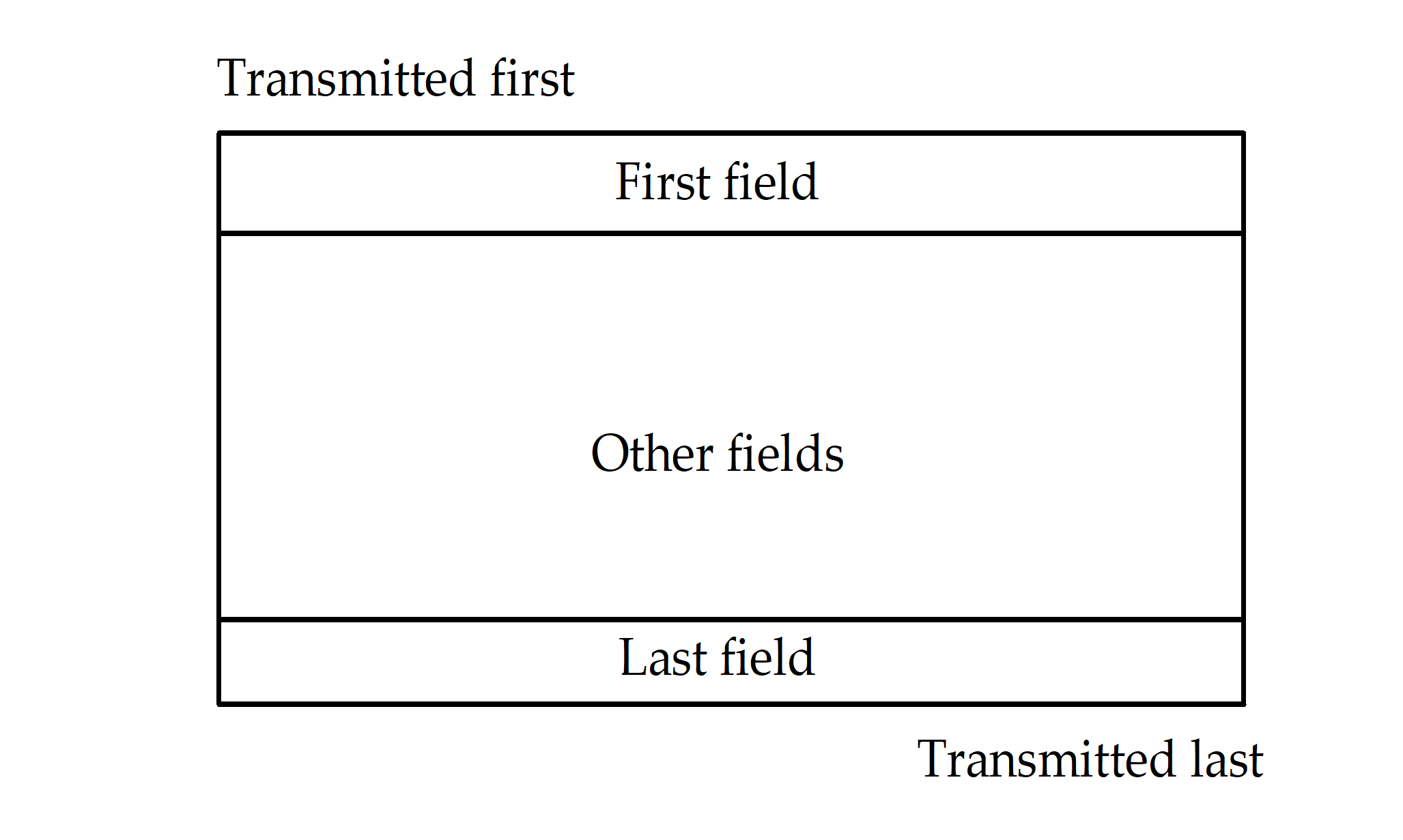 Figure 31: Graphical packet notation
The second packet representation is textual. Each field is enclosed in chevrons <>. The fields comprising a packet are written left to right in the order that they are transmitted. The example below is equivalent to that shown in Figure 31.
For example: <First field><Other fields><Last field>
State diagram notation
All state diagrams in this Standard use the style shown in Figure 32. States are represented by ellipses with the state name written inside the ellipse in bold. Actions to take while in a particular state are written in italics inside the ellipse underneath the state name. Transitions from one state to another are indicated by arrows. The event that causes a transition is written alongside the arrow. Unconditional transitions are indicated by arrows without an event name written next to it. Reset conditions are indicated by transition arrows that start in empty space. Transitions can be enabled by a guarded condition so that the transition only takes place if the guard condition is true. Guard conditions are written in square brackets alongside the transition they affect.
State names referred to in the text of the Standard are in italics e.g. FirstState.
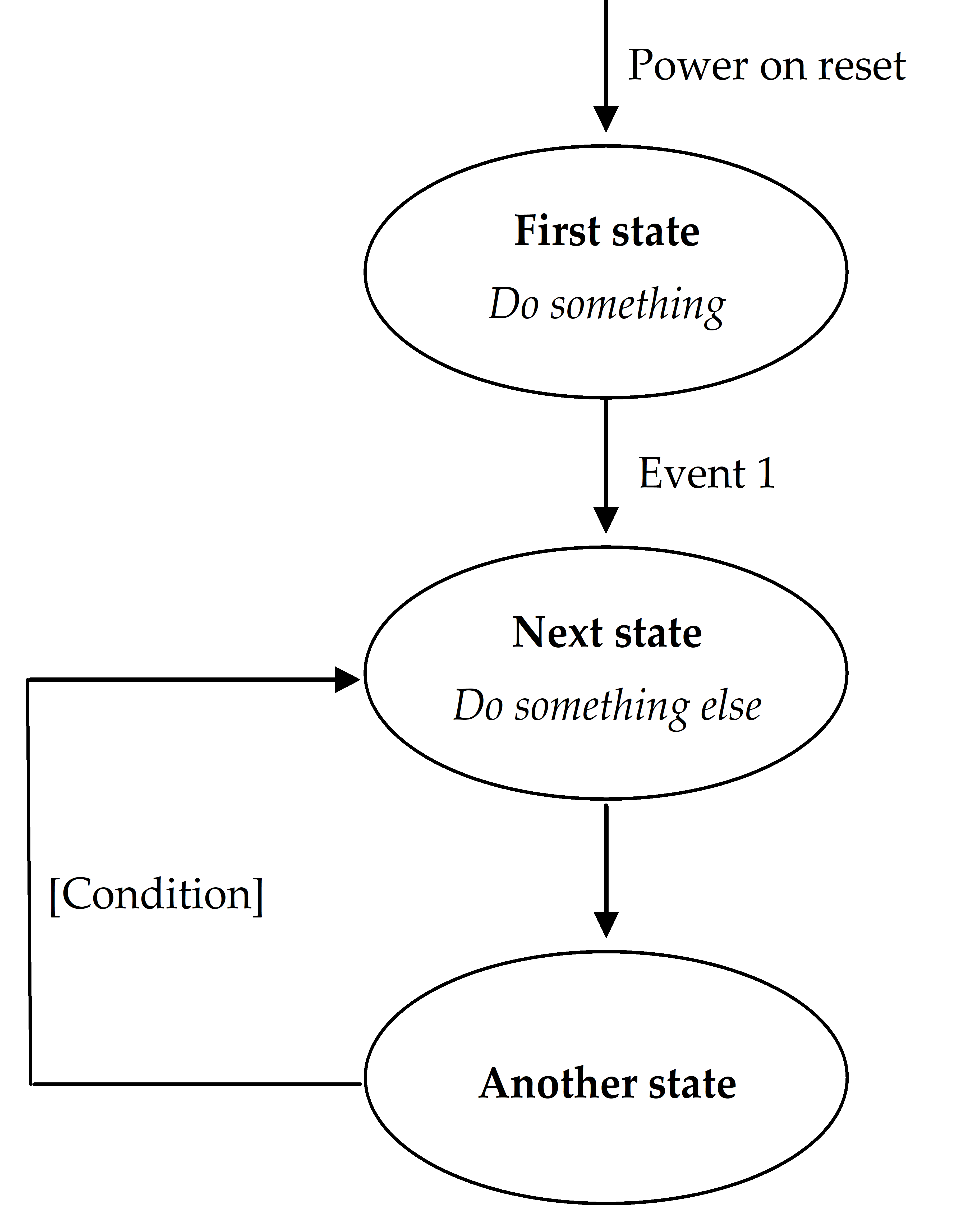 Figure 32: State diagram style
Overall description
Overview
This clause provides an overview of the Standard giving the rationale behind key decisions made in the development of the Standard.
SpaceWire takes into consideration the “DS-DE” part of IEEE Standard 1355-1995 [1], as well as ANSI/TIA/EIA-644 and IEEE Standard 1596.3-1996 [2] Low Voltage Differential Signalling (LVDS). See annex A for details of the main differences between SpaceWire and IEEE Standard 1355-1995 and the reasons for those differences.
SpaceWire is a fullduplex, bidirectional, serial, pointtopoint data link. It encodes data using two differential signal pairs in each direction. That is a total of eight signal wires, four in each direction.
Physical level
Overview
The physical level of the Standard covers cables, connectors, cable assemblies and printed circuit board (PCB) tracks. SpaceWire was developed to meet the EMC specifications of typical spacecraft.
Cables
The SpaceWire cable comprises four twisted pair wires with a separate shield around each twisted pair and an overall shield.
To achieve a high data signalling rate with SpaceWire over distances up to 10 m a cable with the following characteristics is used:
characteristic impedance matched to the line termination impedance;
low signalsignal skew between each signal in a differential pair and between Data and Strobe pairs;
low signal attenuation;
low crosstalk;
good EMC performance.
Connectors
The SpaceWire connector has eight signal contacts plus a screen termination contact. A ninepin microminiature Dtype is specified as the SpaceWire connector. This type of connector is available qualified for space use.
Cable assemblies
SpaceWire cable assemblies are made from SpaceWire cable up to 10 m in length terminated at each end by ninepin microminiature Dtype plugs.
Printed circuit board tracks
SpaceWire includes specifications for running SpaceWire signals over printed circuit boards including backplanes using pairs of tracks with 100 differential impedance.
Electromagnetic compatibility
SpaceWire was developed to meet the electromagnetic compatibility (EMC) specifications of typical spacecraft. EMC testing was performed by Patria Finavitec Oy with support from the following EMC specifications derived from the EMC specifications for the Rosetta [3] and other ESA missions. The testing covered:
Radiated emission, electric and magnetic fields;
Radiated susceptibility, electric and magnetic fields;
Conducted susceptibility;
Conducted emission;
Electrostatic discharge;
Signalling rate;
Bit error rate;
Fault isolation; and
Power consumption.
The EMC test results are provided in [4].
Signal level
Overview
The signal level part of this Standard covers signal voltage levels, noise margins and signal encoding.
Signal level and noise margins
Low voltage differential signalling or LVDS (ANSI/TIA/EIA644) is specified as the signalling technique to use in SpaceWire.
LVDS uses balanced signals to provide very highspeed interconnection using a low voltage swing (350 mV typical). The balanced or differential signalling provides adequate noise margin to enable the use of low voltages in practical systems. Low voltage swing means low power consumption at high speed. LVDS is appropriate for connections between boards in a unit, and unit to unit interconnections over distances of 10 m or more.
The signalling levels used by LVDS are illustrated in Figure 41.
 Figure 41: LVDS signalling levels
A typical LVDS driver and receiver are shown in Figure 42, connected by a media (cable or PCB traces) with 100 differential impedance.
Figure 42: LVDS operation
The LVDS driver uses current mode logic. A constant current source of around 3,5 mA provides the current that flows out of the driver, along the transmission medium, through the 100 termination resistance and back to the driver via the transmission medium. Two pairs of transistor switches in the driver control the direction of the current flow through the termination resistor. When the driver transistors marked “+” in Figure 42 are turned on and those marked “-” are turned off, current flows as indicated by the arrows on the diagram creating a positive voltage across the termination resistor. When the two driver transistors, marked “-”, are turned on and those marked “+” are turned off, current flows in the opposite direction producing a negative voltage across the termination resistor. LVDS receivers are specified to have high input impedance so that most of the current flows through the termination resistor to generate around 350 mV with the nominal 3,5 mA current source.
LVDS has several features that make it very attractive for data signalling [5]:
Near constant total drive current (+3,5 mA for logic 1 and -3,5 mA for logic 0) which decreases switching noise on power supplies.
High immunity to ground potential difference between driver and receiver - LVDS can tolerate at least 1 V ground difference.
High immunity to induced noise because of differential signalling normally using twistedpair cable.
Low EMI because small equal and opposite currents create small electromagnetic fields which tend to cancel one another out.
Not dependent upon particular device supply voltages.
Simple 100 termination at receiver.
Failsafe operation, i.e. the receiver output goes to the high state (inactive) whenever
the receiver is powered and the driver is not powered;
the inputs are short circuited;
input wires are disconnected.
Power consumption is typically 50 mW per driver - receiver pair for LVDS compared to 120 mW for ECL or PECL.
The following two standards deal with LVDS
ANSI/TIA/EIA-644 that defines the driver output characteristics and the receiver input characteristics only.
IEEE Standard 1596.3 that defines the signalling levels used and the encoding for packet switching used in SCI data transfers [2].
The signal levels and noise margins for SpaceWire are defined taking into consideration the ANSI/TIA/EIA-644 since this deals with LVDS only whereas IEEE Standard 1596.3 [2] is concerned with the use of LVDS specifically for SCI.
Data encoding
SpaceWire uses DataStrobe (DS) encoding. This is a coding scheme which encodes the transmission clock with the data into Data and Strobe so that the clock can be recovered by simply XORing the Data and Strobe lines together. The data values are transmitted directly and the strobe signal changes state whenever the data remains constant from one data bit interval to the next. This coding scheme is illustrated in Figure 43. The DS encoding scheme is also used in the IEEE Standard 1355-1995 [1] and IEEE 1394-1995 (Firewire) Standard [6].
The reason for using DS encoding is to improve the skew tolerance to almost 1bit time, compared to 0,5 bit time for simple data and clock encoding.
 Figure 43: DataStrobe (DS) encoding
A SpaceWire link comprises two pairs of differential signals, one pair transmitting the D and S signals in one direction and the other pair transmitting D and S in the opposite direction. That is a total of eight wires for each bidirectional link.
Character level
SpaceWire takes into consideration the character level protocol defined in IEEE Standard 1355-1995 [1], but it additionally includes TimeCodes to support the distribution of system time.
There are two types of characters:
Data characters which hold an eightbit data value, transmitted least significant bit first. Each data character contains a parity bit, a datacontrol flag and the eight bits of data. The parity bit covers the previous eight bits of a data character or two bits of a control character, the current parity bit and the current datacontrol flag. It is set to produce odd parity so that the total number of 1’s in the field covered is an odd number. The datacontrol flag is set to zero to indicate that the current character is a data character.
Control characters which hold two control bits. Each control character is formed from a parity bit, a datacontrol flag and two control bits. The datacontrol flag is set to one to indicate that the current character is a control character. Parity coverage is similar to that for a data character. One of the four possible control characters is the escape code (ESC). This can be used to form control codes. Two control codes are specified and valid which are the NULL code and the TimeCode.
NULL is formed from ESC followed by the flow control token (FCT). NULL is transmitted whenever a link is not sending data or control tokens, to keep the link active and to support link disconnect detection.
The TimeCode is used to support the distribution of system time across a network. A TimeCode is formed by ESC followed by a single datacharacter.
The data and control characters are illustrated in Figure 44.
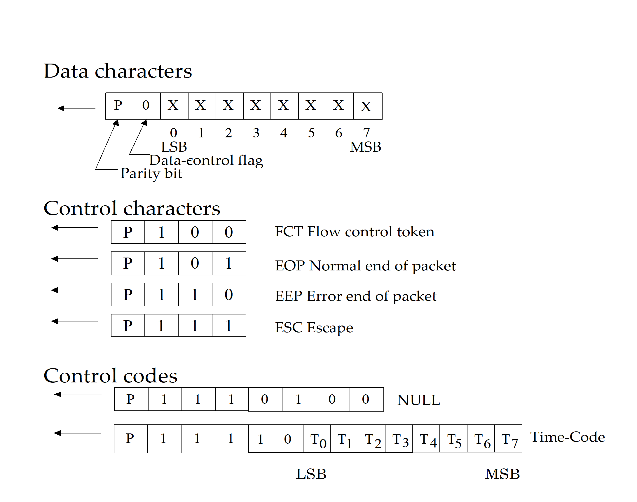 Figure 44: Data and control characters
Exchange level
The exchange level protocol is a significantly more capable version than that defined in IEEE Standard 1355-1995 [1] and provides the following services:
Initialization: Following reset the link output is held in the reset state until it is instructed to start and attempts to make a connection with the link interface at the other end of the link. A connection is made following a handshake that ensures both ends of the link are able to send and receive characters successfully. Each end of the link sends NULLs, waits to receive a NULL, then sends FCTs and waits to receive an FCT. Since a link interface cannot send FCTs until it has received a NULL, receipt of one or more NULLs followed by receipt of an FCT means that the other end of the link has received NULLs successfully and that full connection is achieved.
Flow control: A transmitter can only transmit NChars (normal characters, which are data characters, EOP or EEP) if there is space for them in the host system receive buffer at the other end of the link. The host system indicates that there is space for eight more NChars by requesting the link transmitter to send a flow control token (FCT). The FCT is received at the other end of the link (end B) enabling the transmitter at end B to send up to eight more NChars. If there is more room in the host receive buffer then multiple FCTs can be sent, one for every eight spaces in the receive buffer. Correspondingly, if multiple FCTs are received then it means that there is a corresponding amount of space available in the receiver buffer, e.g. four FCTs means that there is room for 32 NChars.
Detection of disconnect errors: Link disconnection is detected when following reception of a data bit no new data bit is received within a link disconnect timeout window (850 ns). Once a disconnection error is detected, the link attempts to recover from the error (see Figure 45).
Detection of parity errors: Parity errors occurring within a data or control character are detected when the next character is sent, since the parity bit for a data or control character is contained in the next character. Once a parity error is detected, the link attempts to recover from the error (see Figure 45).
Link error recovery: Following an error or reset the link attempts to resynchronize and restart using an “exchange of silence” protocol (see Figure 45). The end of the link that is either reset or that finds an error, ceases transmission. This is detected at the other end of the link as a link disconnect and that end stops transmitting too. The first link resets its input and output for 6,4 s to ensure that the other end detects the disconnect. The other end also waits for 6,4 s after ceasing transmission. Each link then waits a further 12,8 s before starting to transmit. These periods of time are sufficient to ensure that the receivers at both ends of the link are ready to receive characters before either end starts transmission. The two ends of the link go through the NULL or FCT handshake to reestablish a connection and ensure proper character synchronization.
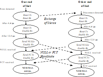 Figure 45: Link restart
Packet level
The packet level protocol follows the packet level protocol defined in IEEE Standard 1355-1995 [1]. It defines how data is encapsulated in packets for transfer from source to destination. The format of a packet is illustrated in Figure 46.
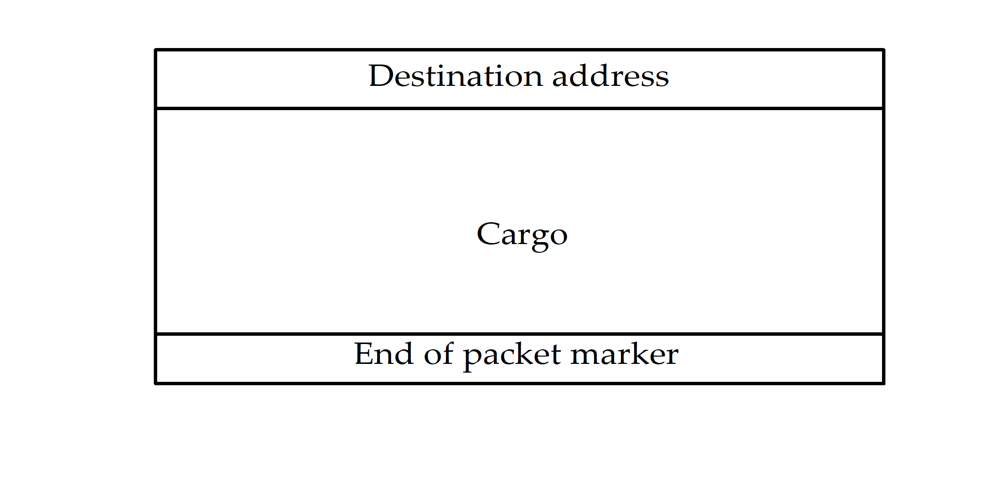 Figure 46: Packet format
The “destination address” is a list of zero or more data characters that represent the destination identity. This list of data characters represents either the identity code of the destination node or the path that the packet takes to get to the destination node.
The “cargo” is the data to transfer from source to destination.
The “end of packet marker” is used to indicate the end of a packet. Two end of packet markers are defined:
EOP normal end_of_packet marker - indicates end of packet;
EEP error end_of_packet marker - indicates that the packet is terminated prematurely due to a link error.
Since there is no start_of_packet marker, the first data character following an end_of_packet marker (either EOP or EEP) is regarded as the start of the next packet.
The packet level protocol provides support for packet routing via wormhole routing switches [7].
Network level
The network level defines what a SpaceWire network is, describes the components that make up, explains how packets are transferred across it, and details the manner in which it recovers from errors.
A SpaceWire network is made up of a number of SpaceWire nodes interconnected by SpaceWire routing switches. SpaceWire nodes are the sources and destinations of packets and provide the interface to the application systems. SpaceWire nodes can be directly connected together using SpaceWire links or they can be interconnected via SpaceWire routing switches using SpaceWire links to make the connection between node and routing switch. A SpaceWire routing switch has several link interfaces connected together by a switch matrix, which allows any link input to pass the packets that it receives on to any link output for retransmission.
Application programming interface
The application programming interface (API) is not defined in this Standard. However, a typical application interface comprises the following services:
Open link: Starts a link interface and attempts to establish a connection with the link interface at the other end of the link.
Close link: Stops a link and breaks the connection.
Write packet: Sends a packet out of the link interface.
Read packet: Reads a packet from the link interface.
Status and configuration: Reads the current status of the link interface and sets the link configuration.
Physical level (normative)
Overview
The physical level provides the actual interface between nodes including both the mechanical and electrical interface. This clause covers:
cable construction,
connectors,
cable assemblies, and
PCB and backplane tracking.
Cables
Generic
The SpaceWire cable shall be constructed according to ESCC 3902/003 and the specific details given in the following clauses.
The SpaceWire cable shall comprise four twisted pair wires with a separate shield around each twisted pair and an overall shield as illustrated in Figure 51.
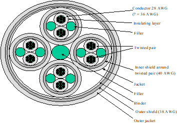 Figure 51: SpaceWire cable construction
Inner conductors
Conductor
Each signal wire shall be 28 AWG, constructed from seven strands of 36 AWG silvercoated, highstrength copper alloy.
The thickness of the silver coating shall be 2,0 m minimum.
Tensile characteristics
The minimum elongation of each strand shall be 6,0 %.
The tensile strength of each strand shall be at least 350 N/mm2.
Insulator
Each signal shall be insulated using expanded, microporous PTFE with only those additives for processing and pigmentation.
Insulator colour
The insulator around the signal wires shall be white.
Electrical characteristics
The maximum DC resistance of the inner conductor shall be 256 /km.
Twisted pair
Laylength
The laylength of the two insulated conductors comprising a differential signal pair shall not be less than 12 times and not more than 16 times the outside diameter of the unshielded twisted pair.
Fillers
Fillers shall be used with the differential signal pairs so as to ensure a smooth and uniform diameter under the shielding in order to contribute to a uniform impedance over the cable.
Filler material
The filler material as used for the differential signal pairs shall be expanded microporous PTFE with only those additives for processing.
Construction of filler
The filler material shall be extruded or wrapped from tapes to a diameter of 1,0 mm.
Shield
Each differential signal pair shall be shielded by a braided shield.
The braided shield type shall be of pushback type and provide not less than 90 % coverage.
Shield wire size
The shield wire size shall be 40 AWG.
Shield material
All strands used in the manufacture of the braided shield shall be silvercoated, soft or annealed oxygenfree high conductivity copper.
The thickness of silver shall be 2,5 m minimum.
Any strand shall show an elongation of 10 % minimum.
Protective sheath
The protective sheath for the shielded differential signal pairs shall be a layer of extruded fluorpolymer PFA with only those additives for processing and pigmentation.
Protective sheath wall thickness
The wall thickness of the protective sheath for the shielded differential signal pair shall be 0,15 mm nominal.
Protective sheath colour
The jacket colour of the differential signal pairs shall be white.
Characteristic impedance
The characteristic impedance of each differential signal pair shall be (100 6) differential impedance.
Skew
The skew between each signal in each differential signal pair shall be less than 0,1 ns/m.
Complete cable
Construction
Four sets of differential signal pairs shall be twisted together not less than 12 times and not more than 16 times the outside diameter of two shielded and jacketed differential signal pairs.
Filler
A filler shall be used in the centre of the four differential signal pairs so as to ensure a smooth and uniform diameter under the shielding in order to contribute to a uniform impedance over the cable.
Filler material
The filler material as used for the complete cable shall be microporous PTFE with only those additives for processing.
Construction of filler
The filler material shall be extruded or wrapped from tapes to a diameter of 1,0 mm.
Binder
A binder shall be applied over the four differential signal pairs and central filler to keep the signal pairs and filler together in a fixed position.
Binder material
The material shall be virgin, wrapped, expanded microporous PTFE with only those additives for processing.
Binder construction
The material shall be wrapped with an overlap of 50 % maximum.
Outer shield
The set of four jacketed and screened differential signal pairs shall be shielded by an outer braided shield.
The braided shield type shall be of pushback type and provide not less than 90 % coverage.
Outer shield wire size
The shield wire size shall be 38 AWG.
Outer shield material
All strands used in the manufacture of the braided shield shall be silvercoated, soft or annealed oxygenfree high conductivity copper.
The thickness of silver shall be 2,5 m minimum.
Any strand shall show an elongation of 10 % minimum.
Shield isolation
The twisted pair shields shall not make contact with one another nor with the outer shield.
Outer jacket
The outermost jacket over the four twisted screened and jacketed differential signal pairs shall be a layer of extruded Fluoropolymer PFA with only those additives for processing and pigmentation.
Outer jacket wall thickness
The wall thickness of the jacket for the shielded differential signal pair shall be 0,25 mm nominal.
Jacket colour
The colour of the jacket shall be white.
There shall be no identifying marking on the cable jacket.
Applying pressure to the cable during the marking process can adversely affect the electrical properties of the cable.
Signal skew
The skew between the parts of the differential signal in one differential signal pair shall be 0,1 ns/m maximum.
The skew between one differential signal pair and each other differential signal pair within the cable shall be 0,15 ns/m maximum.
Cable physical parameters
Cable diameter
The outside diameter of the complete cable shall be 7 mm maximum.
Cable minimum bend radius
The minimum bend radius of complete cable shall be 45 mm.
Adhesion of inner conductor
The minimum stripping force shall be 1,0 N.
Cable weight
The maximum weight of the SpaceWire cable shall be 80 g/m.
Cable maximum ratings
The maximum ratings defined in Table 1 shall be met.
The total temperature of the wire (i.e. ambient plus rise) shall not exceed the maximum operating temperature of the wire.
Table 51: SpaceWire cable maximum ratings
|
No.
|
Characteristics
|
Symbol
|
Maximum ratings
|
Unit
|
Remarks
|
|
1
|
Operating voltage (continuous)
|
Vop
|
200
|
Vrms
|
|
|
2
|
Current
|
I
|
1,5
|
A
|
|
|
3
|
Operating rate
|
FM
|
400
|
Mb/s
|
|
|
4
|
Operating temperature range
|
Top
|
-200 to +180
|
°C
|
Tamb a
|
|
5
|
Storage temperature range
|
Tstg
|
-200 to +180
|
°C
|
|
|
a The specified current generates a temperature rise of approximately 50 C above ambient temperature in a vacuum environment. See 5.2.5.5b for precautions to take on the total temperature of the wire.
| |||||
Connectors
General
The SpaceWire connector shall be a nine contact microminiature Dtype with solder contacts, as defined in ESCC 3401/071, or crimp contacts.
Receptacles
Receptacles shall be used on board and unit assemblies.
Receptacles shall be equipped with female contacts.
Receptacles with flying leads should be used for connection to a PCB rather than PCB mounting connectors to improve mechanical shock and vibration resistance of the unit.
Soldering shall conform to ECSS-Q-ST-70-08.
Crimping shall conform to ECSS-Q-ST-70-26.
Plugs
Plugs shall be used on cable assemblies.
Plugs shall be equipped with male contacts as follows:
- The SpaceWire conductors directly soldered or crimped to the contacts as described in clause 5.4.
- The overall shield of the SpaceWire connected to the shell via an EMI backshell.
Soldering shall conform to ECSS-Q-ST-70-08.
Crimping shall conform to ECSS-Q-ST-70-26.
Connector contact identification
The connector contact identification given in Table 52 and Figure 52 shall be used.
Table 52: Connector contact identification
|
Contact number
|
Signal name
|
|
1
|
Din+
|
|
2
|
Sin+
|
|
3
|
Inner shield
|
|
4
|
Sout-
|
|
5
|
Dout-
|
|
6
|
Din-
|
|
7
|
Sin-
|
|
8
|
Sout+
|
|
9
|
Dout+
|
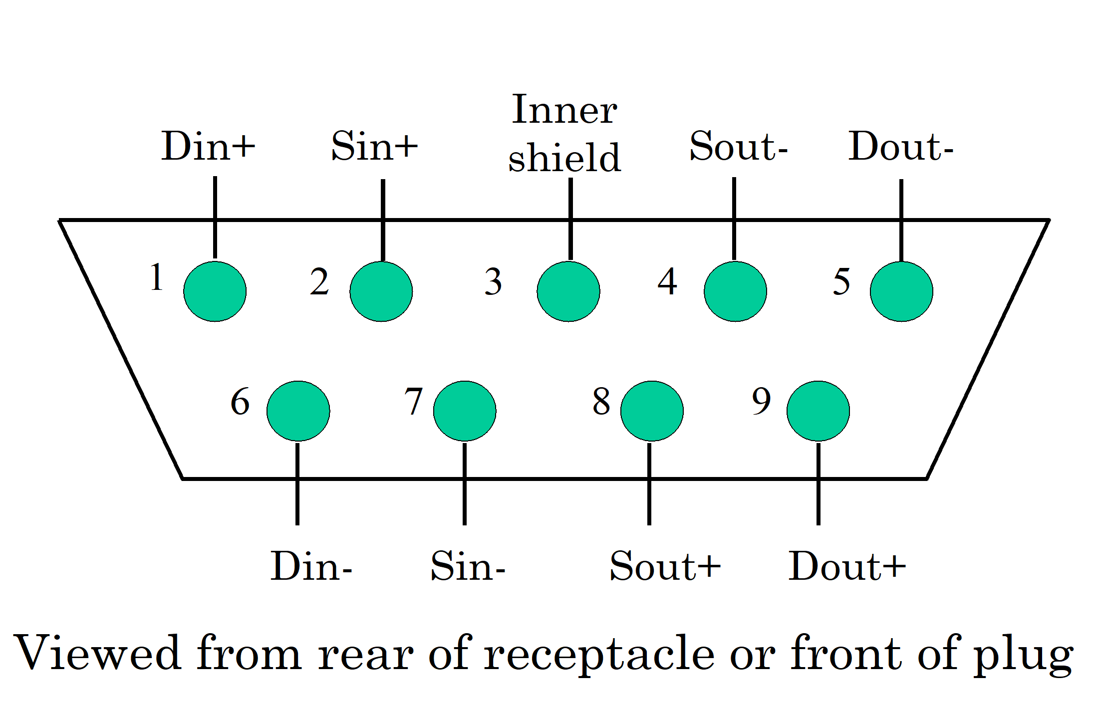 Figure 52: SpaceWire connector contact identification
Inner shield connection
The inner shield connection shall be connected to the inner shield of the SpaceWire cable.
This inner shield of the SpaceWire cable should be connected to signal ground according to the EMC requirements of the mission.
The connection referred in b. should be performed via a parallel resistor and capacitor.
See clause 5.4 for the cable connection to pin 3 of the connector.
Flying lead connectors
Flying lead connectors should be used for connection to a PCB.
Flying lead connectors used for connection to a PCB should have all the leads cropped to the same short length (less than 25 mm) and the wires comprising the differential signal pairs should be twisted together.
This helps to minimize the discontinuity in impedance caused by the connector.
PCB mounting connectors
PCB mounting rightangled connectors should not be used.
If a PCB mounting rightangled connector is used, signal path length compensation shall be performed by adjusting the length of tracks on the PCB, as follows.
If a PCB mounting rightangled connector is used, signals connected to the top row shall be given correspondingly shorter PCB track lengths than tracks going to the bottom row.
The reason is that the topmost row of pins on the rightangled connect have longer leads than the bottom row.
If a PCB mounting rightangled connector is used, track length compensation shall be performed at the connector end of the PCB tracks to maintain the differential signal across the PCB.
Cable assembly
Overview
Cable assemblies consist of two identical plug connectors joined by a length of cable.
Cable length
The maximum length of the cable assembly should be 10 m to ensure that the end to end skew and jitter introduced by the cable assembly does not exceed the maximum budget for the cable.
Longer length cables may be used at slow data signalling rates provided that the signal attenuation (see clause 6) and system jitter and skew limits are not violated at the operating data signalling rate (see clause 6.6.4).
Cable connections
The connector contacts shall be terminated as shown in Figure 53 and Table 53.
The cable signal wires cross over to achieve a transmit to receive interconnection, e.g. Dout+ is connected to Din+ .
The individual shields of the differential signal pairs carrying the output signals Dout+, Dout- and Sout+ and Sout- shall be connected together and to pin 3 of the connector.
The shields are terminated at the end of the cable from which the signals are being driven, following good EMC practice. In this way two of the differential pairs are connected at one end of the cable and the remaining two at the other end. A symmetrical arrangement results, avoiding the problem of having to know which end of the cable is which during installation.
A metal shell shall be used for each connector to provide necessary shielding of the connector.
The outer shield of the cable shall be bonded to the connector shell via a low impedance connection (less than 1 ).
The metal shell shall be bonded to the main body of the connector via a low impedance connection (less than 1 ).
 Figure 53: SpaceWire cable assembly
Table 53: Cable assembly signal wire connections
|
Signal at A end
|
Pin at A end
|
|
Pin at B end
|
Signal at B end
|
|
A-Din+
|
1
|
- Connection -
|
9
|
B-Dout+
|
|
A-Din-
|
6
|
- Connection -
|
5
|
B-Dout-
|
|
A-Sin+
|
2
|
- Connection -
|
8
|
B-Sout+
|
|
A-Sin-
|
7
|
- Connection -
|
4
|
B-Sout-
|
|
A- (Drains of pairs 5,9 and 4,8)
|
3
|
- No Connection -
|
3
|
B-(Drains of pairs 5,9 and 4,8)
|
|
A-Sout+
|
8
|
- Connection -
|
2
|
B-Sin+
|
|
A-Sout-
|
4
|
- Connection -
|
7
|
B-Sin-
|
|
A-Dout+
|
9
|
- Connection -
|
1
|
B-Din+
|
|
A-Dout-
|
5
|
- Connection -
|
6
|
B-Din-
|
|
A-Shield
|
Shell
|
- Connection -
|
Shell
|
B-Shield
|
PCB and backplane tracking
General
As well as routing SpaceWire signals through a cable, the signals can also be transmitted across a PCB or along a backplane.
Only point to point connections are supported on a PCB or backplane, not multidrop bus structures. Bus type structures are built from point to point connections between nodes on the backplane.
Differential signal pairs
Differential impedance
Differential pair signals shall run on a pair of close, parallel PCB tracks with a differential impedance of (100 6) .
This differential impedance can be achieved by adjusting the track thickness, width, separation and height above the ground plane.
Difference in track length for a differential pair
To avoid skew between the two parts of the differential signal, the difference in track length between the two signals from a differential pair shall be less than 5 % of the track length and no more than 5 mm.
Difference in track length for Data and Strobe
The skew introduced between the Data and Strobe (D and S) signals shall be minimized as specified here. For PCB tracks, skew is controlled by making the tracks all close to the same length.
The difference in track length between the Data and Strobe signals shall be less than 5 % of the track length and no more than 5 mm.
Signal level (normative)
Low voltage differential signaling (LVDS)
SpaceWire shall use low voltage differential signalling (LVDS) with electrical characteristics as defined in ANSI/TIA/EIA-644.
Failsafe operation of LVDS
When any of the following fault conditions occur, the receiver outputs shall not oscillate and shall be locked to high logic level provided that a noise threshold of 10 mV is not exceeded at the receiver input.
- Driver not powered.
- Driver disabled.
- Driver not connected to receiver.
- Receiver inputs open circuit (i.e. cable or wire in cable disconnected).
- Receiver inputs shorted together.
When the driver is not powered its output should be high impedance i.e. > 100 k.
When the receiver is not powered its input should be high impedance i.e. > 100 k.
Signal coding
Datastrobe (DS)
SpaceWire shall use DataStrobe (DS) encoding.
DS encoding is defined in clause 5.3.5 of IEEE Standard 1355-1995 [1] and also defined in IEEE Standard 1394-1995 [6]. See annex A for details of the differences between this Standard and IEEE Standard 1355-1995 and the reasons for those differences.
The data bit stream to transmit shall be encoded using two signals Data and Strobe as follows.
The Data signal shall follow the data bit stream, i.e. be high when the data bit is 1 and low when the data bit is 0.
The Strobe signal shall change state whenever the Data does not change from one bit to the next.
The DS encoding is illustrated in Figure 61.
Figure 61: DataStrobe (DS) encoding
Simultaneous transition on data and strobe signals
As data corruption following simultaneous transitions on the Data and Strobe lines is expected, the SpaceWire receiver shall be tolerant of simultaneous transitions on the Data and Strobe lines, i.e. the receiver shall not hang up.
When the SpaceWire transmitter is reset it shall be a controlled reset avoiding simultaneous transitions of Data and Strobe signals.
- 1 For example, after stopping transmission the Strobe signal can be reset first, followed by the Data signal.
- 2 Simultaneous transitions on the Data and Strobe lines are not part of the normal operation of SpaceWire. They can occur, however, either when a SpaceWire cable is plugged in while the transmitter is trying to make a connection, or when the LVDS driver or receiver circuits are enabled while the transmitter is trying to make a connection.
Differential DS
SpaceWire shall use low voltage differential signalling (LVDS) for the Data and Strobe signals.
SpaceWire link
A SpaceWire link shall comprise two pairs of differential signals, one pair transmitting the D and S signals in one direction and the other pair transmitting D and S in the opposite direction.
This is a total of eight wires for each bidirectional link.
Data signalling rate
Minimum data signalling rate
The minimum data signalling rate at which a SpaceWire link shall operate is 2 Mb/s.
- 1 The minimum data signalling rate is the lowest data signalling rate at which a SpaceWire link can operate.
- 2 The minimum data signalling rate is set by the disconnect timeout (clause 8.9.2.1 and 8.11.2) to greater than 1,18 Mb/s, i.e. 1/850 ns.
Maximum data signalling rate
The maximum data signalling rate shall be defined.
The maximum data signal rate is the highest data signalling rate at which a SpaceWire link can operate and is defined by consideration of signal skew and jitter (see clause 6.6.4).
Operational data signalling rate
The link in one direction can operate at a different data signalling rate to the same link in the opposite direction.
Links within a system can operate at different data signalling rates.
A SpaceWire link can operate at any data signalling rate between the minimum data signalling rate and the maximum possible data signalling rate.
Effects of skew and jitter
Skew and jitter overview
The maximum data signalling rate that can be achieved is different from one system to another, depending on several factors such as cable length, driverreceiver technology, and encoderdecoder design, and is limited by skew and jitter.
Figure 62 illustrates the effect of skew and jitter on the Data and Strobe signals, where the parameters are as follows:
tskew is the skew between the Data and Strobe signals.
tjitter is the jitter on the Data or Strobe signal. tjitter data = tjitter strobe since they follow identical signal paths (as close as possible).
tdclk is the delay in the receiver from the edge of the Data or Strobe signal, through the XOR operation which produces the clock signal, to the clocking in of the data in the input flipflop. This may be regarded as the setup time for the data input flipflop from the edge of the Data or Strobe signal.
thold is the hold time for the Data signal after the clocking of the data into the input flipflop.
tui is the unit interval or bit period. tui = 1/Fop, where Fop is the link operating data signalling rate.
The tdclk and thold parameters may be combined into a minimum specification for the separation of consecutive edges on the Data and Strobe signals at the input to the decoder, tds = tdclk + thold.
tmargin is the available margin. tmargin = tui – (tskew + 2*tjitter + tdclk + thold).
- 1 Figure 63 illustrates the contributors to skew and jitter in a typical system.
- 2 Table 61,
- Table 62 and Table 63 provide the example jitter and skew budgets at three different operating frequencies (100 Mb/s, 200 Mb/s and 400 Mb/s).
- 3 The example jitter and skew figures for 400 Mb/s operation (Table 63) assume that the LVDS driver or receiver are integrated in the same package as the encoderdecoder.
Timing margin
The maximum data signalling rate for a SpaceWire link shall be set so that the timing margin (tmargin) is greater than zero.
Initial operating data signalling rate
After a reset or disconnect (see clause 8.9.2.1) the SpaceWire link transmitter shall initially commence operating at a data signalling rate of (101) Mb/s.
The SpaceWire link transmitter shall operate at (101) Mb/s until commanded to operate at a different data signalling rate.
- 1 The aim is to provide all systems with a common, slow, initial data signalling rate so that system operation can be validated before switching to higher and possibly widely different data signalling rates.
- 2 This initial slow data signalling rate is applicable to all SpaceWire systems, but they need not be capable of higher data signalling rates.
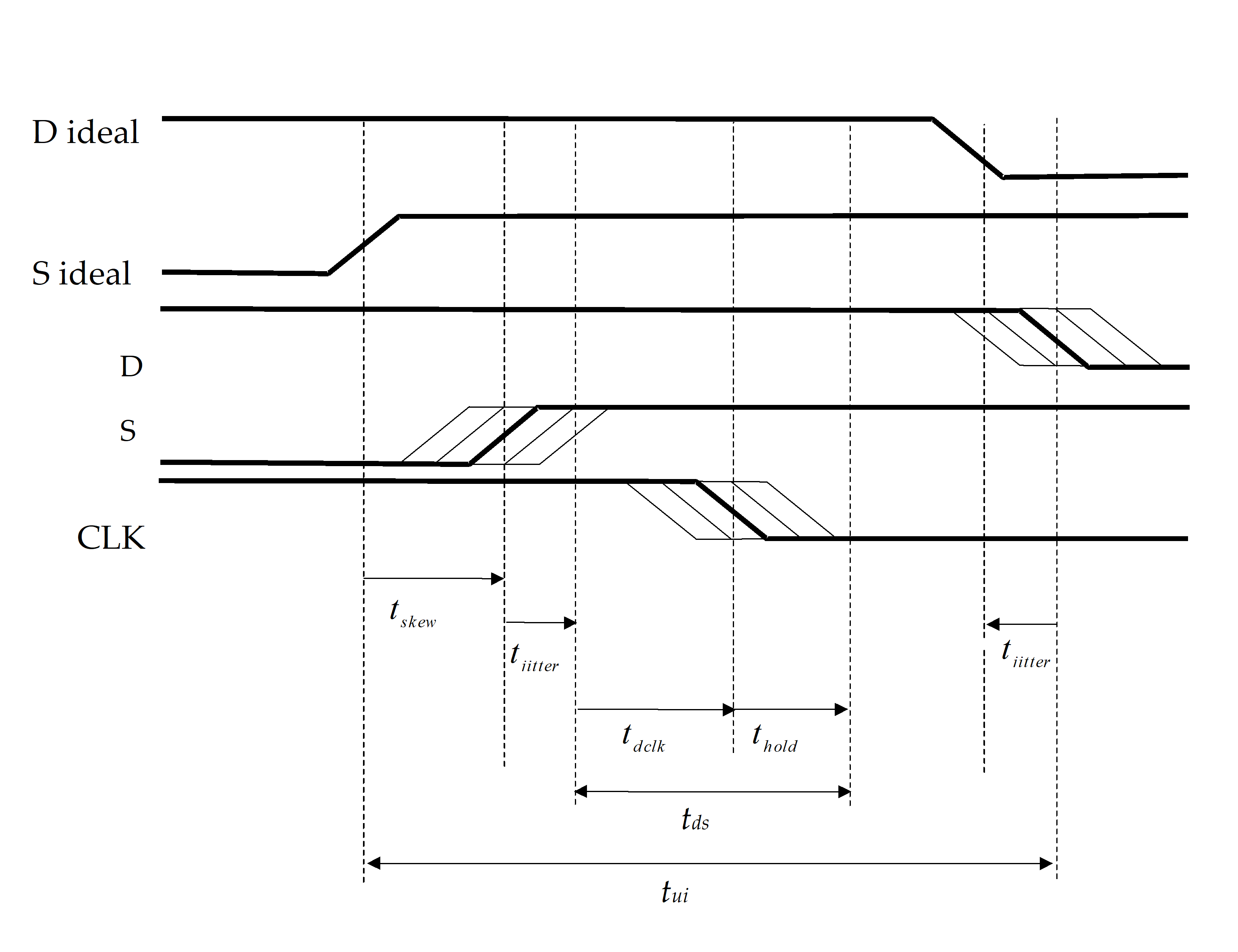 Figure 62: Skew and jitter
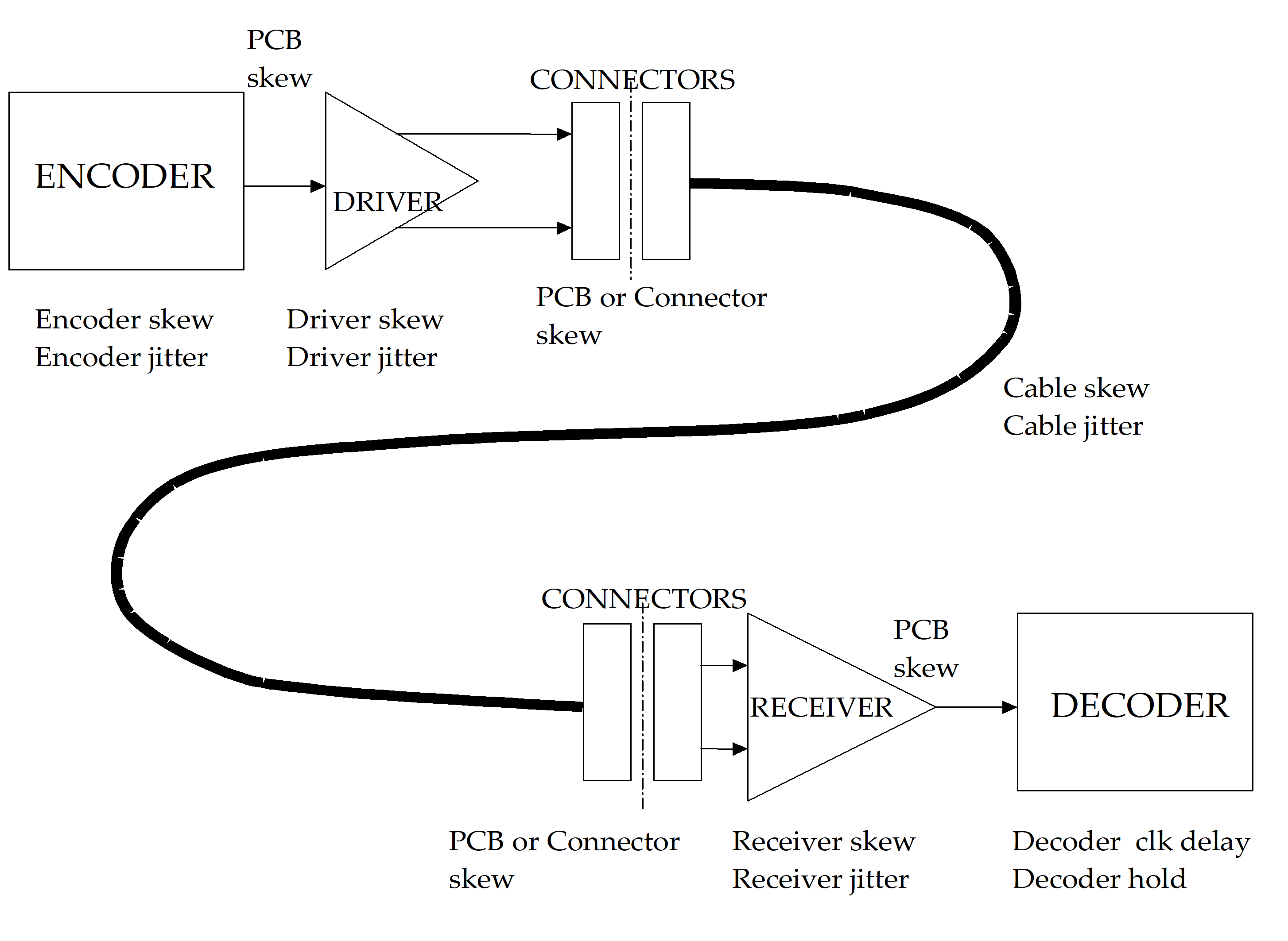 Figure 63: Contributors to skew and jitter
Table 61: Example jitter and skew budget at 100 Mb/s
|
|
Data jitter
|
Strobe jitter
|
Skew
|
Min edge separation
|
Total
|
|
Encoder skew
|
|
|
0,50
|
|
|
|
Encoder jitter
|
0,50
|
0,50
|
|
|
|
|
PCB skew
|
|
|
0,05
|
|
|
|
Driver skew
|
|
|
1,00
|
|
|
|
Driver jitter
|
0,50
|
0,50
|
|
|
|
|
PCB/connector skew
|
|
|
0,10
|
|
|
|
Total transmitter
|
1,00
|
1,00
|
1,65
|
|
3,65
|
|
Cable jitter |
0,50
|
0,50
|
|
|
|
|
Cable skew
|
|
|
1,00
|
|
|
|
Total cable
|
0,50
|
0,50
|
1,00
|
|
2,00
|
|
PCB/connector skew
|
|
|
0,10
|
|
|
|
Receiver skew
|
|
|
1,50
|
|
|
|
Receiver jitter
|
0,50
|
0,50
|
|
|
|
|
PCB skew
|
|
|
0,05
|
|
|
|
Decoder clock delay and hold
|
|
|
|
1,00
|
|
|
Total receiver
|
0,50
|
0,50
|
1,65
|
1,00
|
3,65
|
|
Total system
|
2,00
|
2,00
|
4,30
|
|
8,30
|
|
Margin
|
|
|
|
|
1,70
|
Table 62: Example jitter and skew budget at 200 Mb/s
|
|
Data jittertjitter (ns)
|
Strobejittertjitter (ns)
|
Skewtskew (ns)
|
Min edge separationtds (ns)
|
Total(ns)
|
|
Encoder skew
|
|
|
0,50
|
|
|
|
Encoder jitter
|
0,10
|
0,10
|
|
|
|
|
PCB skew
|
|
|
0,05
|
|
|
|
Driver skew
|
|
|
0,07
|
|
|
|
Driver jitter
|
0,20
|
0,20
|
|
|
|
|
PCB/connector skew
|
|
|
0,10
|
|
|
|
Total transmitter
|
0,30
|
0,30
|
0,72
|
|
1,32
|
|
Cable jitter
|
0,50
|
0,50
|
|
|
|
|
Cable skew
|
|
|
1,00
|
|
|
|
Total cable
|
0,50
|
0,50
|
1,00
|
|
2,00
|
|
PCB/connector skew
|
|
|
0,10
|
|
|
|
Receiver skew
|
|
|
0,12
|
|
|
|
Receiver jitter
|
0,20
|
0,20
|
|
|
|
|
PCB skew
|
|
|
0,05
|
|
|
|
Decoder clock delay and hold
|
|
|
|
1,00
|
|
|
Total receiver
|
0,20
|
0,20
|
0,27
|
1,00
|
1,67
|
|
Total system
|
1,00
|
1,00
|
1,99
|
1,00
|
4,99
|
|
Margin
|
|
|
|
|
0,01
|
Table 63: Example jitter and skew budgets at 400 Mb/s
|
|
Data jittertjitter (ns)
|
Strobejittertjitter (ns)
|
Skewtskew (ns)
|
Min edge separationtds (ns)
|
Total(ns)
|
|
Encoder skew
|
|
|
0,20
|
|
|
|
Encoder jitter
|
0,10
|
0,10
|
|
|
|
|
PCB/connector skew
|
|
|
0,05
|
|
|
|
Total transmitter
|
0,10
|
0,10
|
0,25
|
|
0,45
|
|
Cable jitter
|
0,35
|
0,35
|
|
|
|
|
Cable skew (5m max. length)
|
|
|
0,50
|
|
|
|
Total cable
|
0,35
|
0,35
|
0,50
|
|
1,20
|
|
PCB/connector skew
|
|
|
0,05
|
|
|
|
Receiver jitter
|
0,10
|
0,10
|
|
|
|
|
Decoder clock delay and hold
|
|
|
|
0,50
|
|
|
Total receiver
|
0,10
|
0,10
|
0,05
|
0,50
|
0,75
|
|
Total system
|
0,55
|
0,55
|
0,80
|
0,50
|
2,40
|
|
Margin
|
|
|
|
|
0,10
|
Altering data signalling rate
The transmitter operating rate shall not be changed before the link connection has been made fully.
I.e. the exchangelevel state machine is in the Run state; see clause 8. Once in the Run state (see clause 8.5) the transmitter operating rate can be set at any rate between the minimum (see clause 6.6.1) and the maximum data signalling rate (see clause 6.6.2).
Character level (normative)
Overview
The character level protocol defined in this clause takes into consideration the DSSE and DSDE character level encoding given in IEEE Standard 1355-1995 [1], but it additionally includes TimeCodes for sending system time information across a SpaceWire link. The host interface to the SpaceWire encoderdecoder is specified.
Data characters
As illustrated in Figure 71, a data character shall contain a parity bit, a datacontrol flag and eight bits of data as follows.
The datacontrol flag shall be set to zero to indicate that the current character is a data character.
The eightbit data value shall be transmitted least significant bit first.
Figure 71: SpaceWire data characters
Control characters and control codes
A control character shall be formed from a parity bit, a datacontrol flag and a twobit control code with the datacontrol flag set to one to indicate that the current character is a control character.
The different control characters are illustrated in Figure 72.
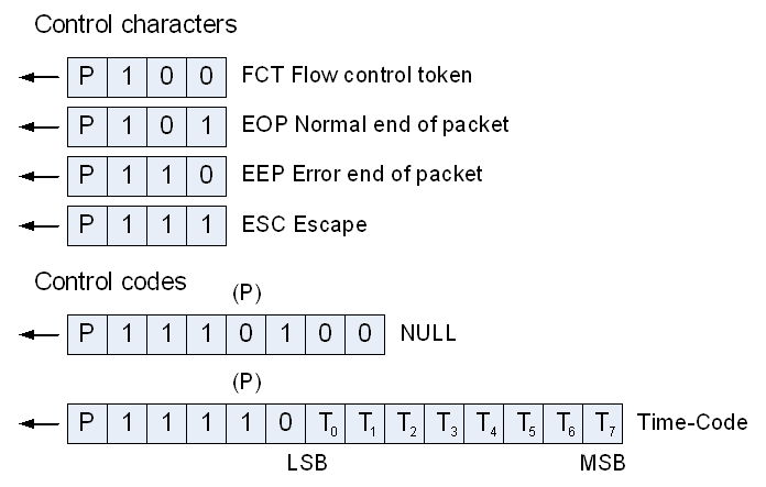 Figure 72: SpaceWire control characters and control codes
The NULL control code shall be formed from ESC followed by the flow control token (FCT).
- 1 The parity bit (P) in the middle of the control code is zero, in accordance with clause 7.4b).
- 2 NULL is transmitted whenever a link is not sending data or control tokens, to keep the link active and to support link disconnect detection (see clause 8).
The time control code (TimeCode) shall be formed from ESC followed by a single data character. - 1 The parity bit (P) in the middle of the TimeCode is one, in accordance with clause 7.4b).
- 2 The TimeCode is used to distribute system time information (see clause 8.12) and control flags isochronous with the timecode distribution.
Six bits of time information shall be held in the least significant six bits of the TimeCode (T0T5) and the two most significant bits (T6, T7) shall contain control flags that are distributed isochronously with the TimeCode.
An escape character (ESC) followed by ESC, EOP or EEP is an invalid sequence and shall be noted as an escape error (see clause 8.9.2.3).
Parity for error detection
A parity bit shall be assigned to each data or control character to support the detection of transmission errors.
The parity bit shall cover the previous eight bits of a data character or two bits of a control character, the current parity bit, and the current datacontrol flag.
The parity bit shall be set to produce odd parity so that the total number of 1’s in the field covered is an odd number.
The coverage of the parity bit is illustrated in Figure 73.
 Figure 73: Parity coverage
Transmit bit pattern after reset or link error
After reset or link error (while in the ErrorReset state, see clause 8) the Data and Strobe signals shall be set to zero.
When the transmitter is enabled after reset the first bit that is sent shall be a parity bit, this bit shall be set to zero so that the first transition shall be on the Strobe line.
This results in the patterns shown Figure 74 appearing when a link is started.
Figure 74: Data and strobe signals on link start
Host interface to transmitter and receiver
When the transmit and receive data interfaces to the host comprise eight data bits and one control flag, the coding given in Table 71 shall be used.
Thus, for example, any code with the control flag set to one and the least significant bit of the data set to zero represents an EOP. This prevents the transmitter being asked to send an invalid control code.
Table 71: Transmitter and receiver host data interface coding
|
Control flag
|
Data bits (MSB LSB)
|
Meaning
|
|
0
|
xxxxxxxx
|
8bit data
|
|
1
|
xxxxxxx0 (use 00000000)
|
EOP
|
|
1
|
xxxxxxx1 (use 00000001)
|
EEP
|
EEP may be written into the transmitter interface
A SpaceWire node is the source of a packet and does not normally send packets that are in error (indicated by termination with an EEP) so normally there is no need to write EEP into the transmitter interface, unless, for example, some exception occurs in the node during the transmission of a packet. As specified in clause 10.5.3, a SpaceWire Router forwards packets where an error has occurred (i.e. packets that are terminated by an EEP) so in the case of a router any EEP is written into the transmitter interface.
For the two control codes (EOP and EEP), Since only the least significant bit is decoded, the following bits should be set:
- when writing to the transmit interface, set to zero the remaining data bits.
- when receiving, set the seven most significant data bits to zero when the control bit is set.
Time interface
The time interface to the host system shall comprise two signals, TICK_IN and TICK_OUT, a sixbit time output port, a sixbit time input port, a twobit control flag input port and a twobit control flag output port.
When TICK_IN is asserted and the link interface is in the Run state (see clause 8.5) it shall cause the transmitter to send a TimeCode immediately after the current character has been transmitted.
TICK_OUT shall be asserted whenever the link interface is in the Run state and the receiver receives a valid TimeCode.
Only one node in a SpaceWire network should have an active TICK_IN signal.
All other nodes should keep the TICK_IN signal not asserted.
The node with the active TICK_IN signal provides the master time reference for the entire SpaceWire network.
A sixbit time output shall be provided from the link receiver to the local time counter.
The other two bits of the time output are the two controlflag outputs and are reserved for future use.
A sixbit time input shall be provided to the link transmitter from the local time counter.
The other two bits of the time input are the two controlflag inputs and are reserved for future use.
The two control flags are reserved for future use and shall both be set to zero.
Exchange level (normative)
Overview
The exchange level protocol takes into consideration the DSSE and DSDE exchange level protocol given in clause 5.7 of the IEEE Standard 1355-1995 [1], but it also includes additional features in the state machine in order to eliminate problems with the ResetLinkCommand and several ambiguities within the IEEE Standard 1355-1995 have been resolved. See annex A for details of the differences between SpaceWire and IEEE Standard 1355-1995 and the reasons for those differences.
The exchange level is responsible for making a connection across a link and for managing the flow of data across the link.
Linkcharacters and normalcharacters (normative)
Definitions
At the exchange level, data and control characters are separated into two types: linkcharacters (LChar) and normalcharacters (NChar).
LChars are those that are used in the exchange level and which are not passed on to the packet level. The flow control token (FCT) character and escape (ESC) character are LChars. The NULL control code (ESC + FCT) and the TimeCode (ESC + data character) are escape sequences and may be regarded as LChars. They are not passed on to the packet level.
NChars are the characters that are passed on to the packet level: data characters and endofpacket markers (EOP and EEP).
Actions
Only NChars shall be passed from the host interface to the link for transmission.
The link interleaves LChars and NChars during transmission, but passes only NChars on to the host interface on the receiving side.
A received character shall not be acted upon until its parity has been checked.
Flow control (normative)
To avoid host receive buffer overflow and subsequent loss of data, data flow across a link shall be controlled using flow control tokens sent from one end of the link (end A) to the other end (end B) to signify that end A is ready to receive some more data.
The FCT (flow control token) is defined in clause 7.3.
A FCT sent out by a link interface shall be used to indicate that there is space for eight more NChars in the host receive buffer.
For each FCT sent the host system shall reserve room in its receive buffer to accommodate eight NChars.
The receive buffer is typically a FIFO memory.
The transmitter shall not transmit any NChars until it has received one or more FCTs to indicate that the receiver is ready.
The transmitter shall keep a credit count of the number of NChars that it has been authorized to send, as follows:
- Each time a link interface receives an FCT its transmitter increments the credit count by eight.
- Whenever the transmitter sends an NChar it decrements the credit count by one.
If the credit count reaches zero the transmitter shall cease sending NChars until it receives another FCT increasing the credit count again to eight.
When the credit count is zero the transmitter shall continue to send LChars.
In state ErrorReset the credit count shall be set to zero.
If an FCT is received when the credit count is at or close to its maximum value (i.e. within eight of the maximum value) then the credit count shall not be incremented and a credit error shall be flagged (see clause 8.5.3.6 and 8.9.2.4).
The credit counter shall hold a maximum credit count of 56 (i.e. seven FCTs).
On reset (or after a link disconnect) the initial number of FCTs to transmit shall be set according to the size of the receive buffer (one FCT for every eight NChars that can be held in the receive buffer) up to a maximum of seven.
If the receive buffer has a capacity of more than 56 (seven FCTs worth) then the number of FCTs to transmit initially shall be set to seven. A maximum of seven FCTs can be outstanding at any time.
A link interface shall keep a count of the number of outstanding NChars it expects to receive, i.e. the number it has asked for by sending FCTs, as follows:
- Increment this outstanding count by eight each time an FCT is transmitted
- Decremented this outstanding count by one each time an NChar is received.
After a link reset or after a link disconnect, the initial value of the outstanding count shall be zero.
The outstanding counter shall contain a maximum count of 56, corresponding to seven FCTs.
An FCT shall not be transmitted unless there is room in the outstanding counter to record eight more outstanding NChars and there is room in the receive buffer to reserve space for those eight more NChars (see clause 8.4.8).
When transmission of a TimeCode or an FCT is requested then it shall be sent immediately, as soon as the transmitter has finished sending the current character (or NULL or TimeCode).
When no TimeCode or FCT is requested and NChars are available from the host interface and the flow control credit count is above zero, the transmitter shall send NChars.
If no TimeCode, FCT or NChar are sent, then the transmitter shall send NULL to indicate that the link is still active (and to prevent the disconnect detection mechanism from being triggered at the other end of the link).
The order of priority for transmission of characters shall be as follows: - TimeCode, highest priority;
- FCTs;
- NChars;
- NULL, lowest priority.
Encoderdecoder block diagram
Overview
An example block diagram of a SpaceWire encoderdecoder is illustrated in Figure 81.
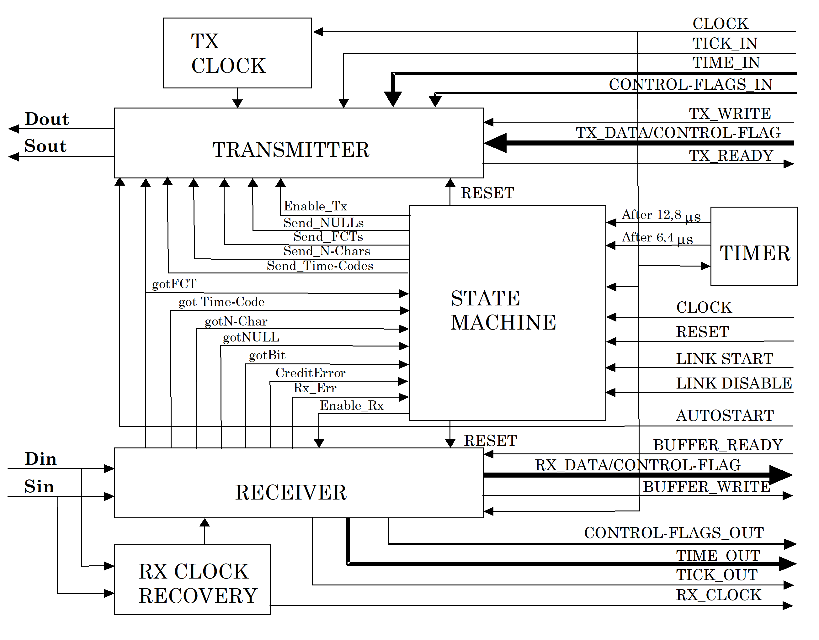 Figure 81: Example SpaceWire link interface block diagram
Transmitter
The transmitter is responsible for encoding data and transmitting it using the DS encoding technique. It receives NChars for transmission from the host system. If there is neither a TimeCode, FCT nor an NChar (data, EOP or EEP) to transmit, the transmitter sends NULL. The transmitter sends NChars only if the host system at the other end of the link (end B) has room in its host receive buffer. This is indicated by the link interface at end B sending an FCT, showing that it is ready to accept another 8 NChars. The transmitter is responsible for keeping track of the FCTs received and the number of NChars sent to avoid input buffer overflow at the other end of the link. To do this the transmitter holds a credit count of the number of characters it has been given permission to send.
The transmitter can be in one of four possible states:
Reset: The transmitter does nothing.
Send NULLs: It can only send NULL on the link. It does not read NChars from the Transmit Host Interface. It does not accept an order to send FCT from the Host System. It does not send TimeCodes.
Send FCTs or NULLs: It sends FCT or NULL but still does not read NChars from the Transmit Host Interface. It does not send TimeCodes.
Send TimeCodes, FCTs, NChars or NULLs: behaviour, sending NULLs, FCTs, TimeCodes and NChars.
The change of state is controlled by the State Machine (see clauses 8.4.6 and 8.5).
The transmitter is also responsible for sending FCTs whenever the local Host System has space to receive eight more N-Chars (see clause 8.4.8). The host system requests the transmitter to send FCTs when it has room for at least eight more N-Chars that have not already been reserved for data by requesting a previous FCT. The transmitter can only send an FCT when it is in state “Send FCTs or NULLs” or “Send TimeCodes. FCTs. NChars or NULLs”.
The transmitter can only send TimeCodes in state d. When the TICK_IN signal is asserted the transmitter sends out a TimeCode as soon as the transmitter has finished sending the current character or control code. The value of the TimeCode is the value of the TIME_IN and CONTROL-FLAGS_IN signals at the point in time when TICK_IN is asserted.
A typical interface between the host system and the transmitter comprises TX_READY, TX_WRITE and TX_DATA (see Figure 81). When the transmitter is ready to receive another NChar from the host system, it asserts the TX_READY signal. When the host system has an NChar to transmit and the TX_READY signal is asserted it may put the NChar onto the TX_DATA lines and assert the TX_WRITE signal. When the transmitter has registered the NChar data it deasserts the TX_READY signal.
Transmit clock
The transmitter can operate at any data signalling rate from the minimum to the maximum possible (see clause 6.6). The transmit clock is responsible for producing the variable data signalling clock signals used by the transmitter. The transmit clock signals are typically derived by dividing down the local system clock or a phase locked loop multiple of the local system clock.
Receiver
The receiver is responsible for decoding the DS signals (Din and Sin) to produce a sequence of NChars (data, EOP, EEP) that are passed on to the host system. It also receives NULLs, FCTs and TimeCodes. NULLs represent an active link. They are flagged to the exchangelevel state machine (see clause 8.5) but are ignored otherwise. When an FCT is received the receiver informs the transmitter so that it can update its credit count accordingly. All other control characters received are flagged to the state machine. The receiver ignores any NChars, LChars, parity errors or escape errors until the first NULL is received. The disconnection detection mechanism within the receiver is enabled as soon as the first bit arrives (i.e. first transition detected on D or S inputs to receiver).
TimeCodes hold system time information. A valid TimeCode causes the assertion of the TICK_OUT signal from the receiver. The value of the TimeCode is placed on the TIME_OUT and CONTROL_FLAGS_OUT outputs when the TICK_OUT signal is asserted. These signals are used by the host system to update or regulate its system clock.
The receiver is also responsible for detection of disconnect, parity, escape and credit errors and it flags these errors to the state machine.
The receiver can be in one of four states:
Reset: The receiver does nothing.
Enabled: The receiver is enabled and is waiting for the first bit to arrive.
GotBit: The receiver has received the first bit (First Bit Received) and disconnect error detection is enabled. The receiver is enabled to listen for NULLs only.
GotNULL: The receiver has received a NULL and is enabled to receive NULLs, FCTs, TimeCodes and NChars. Disconnect, parity and escape error detection is enabled.
The change of state from Reset to Enabled is controlled by the state machine (see clauses 8.4.6 and 8.5).
The receiver is responsible for receiving FCTs from the other end of the link and for passing these FCTs on to the credit counter in the transmitter.
A typical interface between the receiver and the host system comprises BUFFER_READY, BUFFER_WRITE and RX_DATA. When the host system is ready to receive another NChar from the receiver it asserts the BUFFER_READY signal. When the receiver has received an NChar and the BUFFER_READY signal is asserted it puts the NChar onto the RX_DATA lines and assert the BUFFER_WRITE signal. When the host system has registered the NChar data it deasserts the BUFFER_READY signal. If an NChar is received and the BUFFER_READY signal is not asserted then a credit error has occurred (see clause 8.5.3.6).
Receive clock recovery
The receive clock (RX_CLOCK) is recovered by simply XORing the received Data and Strobe signals together. The receive clock recovery circuit provides all the clock signals used by the receiver with the exception of the local clock signal use for disconnect timeout.
State machine
The state machine controls the overall operation of the link interface. It provides link initialization, normal operation and error recovery services. The operation of the state machine is described in the form of a state diagram in clause 8.5.
Timer
The timer provides the After 6,4 s and After 12,8 s timeouts used in link initialization. See the state diagram of Figure 82. The timer is started when the state machine moves into particular states. When the state machine moves into the ErrorReset state the After 6,4 s timer is started. When it moves into the ErrorWait state, Started state or the Connecting state the After 12,8 s timer is started.
Receive buffer data management
The host system is responsible for data buffer management. This makes the SpaceWire interface more versatile and eases partitioning of the error recovery mechanism (see clause 11.4) across the various levels of this Standard. Several different types of host receiver buffering may be implemented:
FIFO buffering – where the size of the FIFO buffer depends upon the particular application.
Memory buffering – where direct memory access (DMA) is used to transfer data to host system memory. As soon as the DMA channel has been set up, several FCTs can be requested immediately to allow the transfer of the data as fast as possible.
No buffering – where the host system is able to accept data at the highest rate that the link interface can provide it. In this case several FCTs can be sent initially, followed by one more every time eight normal characters are received.
Due to the NULL or FCT handshake used during initialization (see clauses 8.5 and 8.7), it is expected that the host system flags that it is ready to receive eight more NChars before or during link initialization (see clause 8.3m). If this is not the case, link initialization fails until the host system is ready to receive data – the link interface is not able to send an FCT. When the host systems at both ends of the link have indicated that they are ready to receive data, then the link connection is made.
Receive FIFO buffering
Most implementations of a SpaceWire interface are likely to include transmit and receive FIFOs. This clause describes one way in which these FIFOs can be used.
After system reset the transmit and receive FIFOs are empty. When link connection is made any data written to the transmit FIFO can be transmitted if FCTs have been received to enable transmission. The receive FIFO is able to accept data while it still has space available. Data is read from the receive FIFO by the host system.
Using a FIFO simplifies the interface to the host system. FIFO halffull or halfempty flags can be used to trigger DMA or processor intervention to read from or write to the FIFO before it becomes full or empty. This helps smooth the flow of data across a link and maintain high data throughput.
State Diagram (normative)
Overview
The complete state transition diagram for the SpaceWire link interface is illustrated in Figure 82.
The state diagram notation is explained in clause 3.4.3.
Figure 82: State diagram for SpaceWire link interface
Definition of states
Overview
A table listing the exit conditions from each state is included in Annex B for clarification purposes.
ErrorReset
The ErrorReset state shall be entered after a system reset, after link operation is terminated for any reason or if there is an error during link initialization.
In the ErrorReset state the Transmitter and Receiver shall all be reset.
When the reset signal is deasserted the ErrorReset state shall be left unconditionally after a delay of 6,4 s (nominal) and the state machine shall move to the ErrorWait state.
Whenever the reset signal is asserted the state machine shall move immediately to the ErrorReset state and remain there until the reset signal is deasserted.
ErrorWait
The ErrorWait state shall be entered only from the ErrorReset state.
In the ErrorWait state the receiver shall be enabled and the transmitter shall be reset.
This allows the receiver to start the disconnection detection mechanism (after registering a transition on the D or S line) and to begin looking for the arrival of a NULL.
If a NULL is received then the gotNULL condition shall be set.
This condition is acted upon in the Started state.
The ErrorWait state shall be left unconditionally after a delay of 12,8 s (nominal) and the state machine shall move to the Ready state.
If, while in the ErrorWait state, a disconnection error is detected, or if after the gotNULL condition is set, a parity error or escape error occurs, or any character other than a NULL is received, then the state machine shall move back to the ErrorReset state.
The ErrorReset and ErrorWait state with their 6,4 s and 12,8 s delays ensure that the receivers at both ends of a link are enabled before either end begins transmission, following an exchange of silence (see clause 8.9.4).
Ready
The Ready state shall be entered only from the ErrorWait state.
In the Ready state the link interface is ready to initialize as soon as it is allowed to do so. The receiver shall be enabled and the transmitter shall be reset.
If a NULL is received then the gotNULL condition shall be set.
This condition is acted upon in the Started state.
The state machine shall wait in the Ready state until the [Link Enabled] guard becomes true (see clause 8.6) and then it shall move on into the Started state.
If, while in the Ready state, a disconnection error is detected, or if after the gotNULL condition is set, a parity error or escape error occurs, or any character other than a NULL is received, then the state machine shall move to the ErrorReset state.
In the Ready state the two receivers are enabled and the state machine is waiting for the local host system to command the link to start.
Started
The Started state shall be entered from the Ready state when the link interface is enabled.
In the Started state the state machine begins making a connection with the link interface at the other end of the link by sending one or more NULLs.
When the Started state is entered a 12,8 s (nominal) timeout timer shall be started.
In the Started state the receiver shall be enabled and the transmitter shall send NULLs.
If a NULL is received then the gotNULL condition shall be set.
The state machine shall move to the Connecting state if the gotNULL condition is set.
The NULL that set the gotNULL condition can have been received in the ErrorWait, Ready or Started states.
In the Started state the sending from the transmitter of at least one NULL shall be requested before moving to the Connecting state.
If, while in the Started state, a disconnection error is detected, or if after the gotNULL condition is set, a parity error or escape error occurs, or any character other than a NULL is received, then the state machine shall move to the ErrorReset state.
If the 12,8 s timeout timer referred to in point b. above expires (i.e. no NULL received since leaving the ErrorReset state) then the state machine shall move to the ErrorReset state.
In the Started state the attempt to make a connection across the link is started. NULLs are transmitted and the receiver is waiting to receive a NULL.
Connecting
The Connecting state shall be entered from the Started state after a NULL is received (gotNULL condition set).
On entering the Connecting state a 12,8 s timeout timer shall be started.
In the Connecting state the receiver shall be enabled and the transmitter shall be enabled to send FCTs and NULLs.
If an FCT is received (gotFCT condition true) the state machine shall move to the Run state.
If, while in the Connecting state, a disconnect error, parity error or escape error is detected, or if any character other than NULL or FCT is received, then the state machine shall move to the ErrorReset state.
If the 12,8 s timeout referred to in point b. above occurs then the state machine shall move to the ErrorReset state.
The Connecting state is entered when the link interface (end A) receives a NULL, waiting then for the reception of an FCT indicating that the other end of the link (end B) has also received a NULL. When the link interface receives a NULL and an FCT it means that communication is established in both directions. If an FCT fails to arrive within 12,8 s then something is wrong with the link connection and so the link interface is reset once more (ErrorReset state) and connection is attempted once again.
Run
The Run state shall be entered from the Connecting state.
In the Run state the receiver is enabled and the Transmitter is enabled to send TimeCodes, FCTs, NChars and NULLs.
If the link interface is disabled, or if a disconnect error, parity error, escape error or credit error is detected (see clause 8.5.3), while in the Run state, then the state machine shall move to the ErrorReset state.
The Run state is the state for normal operation where link connection has been made and LChars and NChars can flow freely in both directions across the link. The link remains in the Run state until an error occurs or until the link is disabled.
Transitions types
Overview
Reset
Reset represents power on reset, other hardware reset or software commanded reset.
After t s
After 6,4 s or after 12,8 s represents a delay of the specified time measured from when the current state is entered. The actual time intervals are nominal delays (see clause 8.11).
[Link Enabled]
[Link Enabled] is a condition for the transition to occur (i.e. a guard). [Link Enabled] can be set true by software or hardware (see clause 8.6).
gotNULL
A gotNULL condition shall be asserted when a NULL is received.
GotNULL means that a NULL detection sequence (see Figure 83) has been received.
NULL detection shall be enabled whenever the receiver is enabled.
Any sequence of bits encountered after reset (ErrorReset state) prior to the first NULL being received shall be ignored.
NULL detection shall include all three parity bits related to the NULL, i.e. the parity bit that covers the datacontrol flag of the ESC character, the parity bit that covers the ESC character, and the parity bit that covers the FCT character.
Hence the NULL shall be detected and gotNULL asserted, when the 011101000 sequence of bits is received as illustrated in Figure 83.
During initialization the character following a NULL is a control character (either another NULL or an FCT) so the last parity bit of the NULL is zero.
If a parity error occurs within the NULL detection sequence then the gotNULL condition shall not be asserted.
Figure 83: NULL detection sequence
gotFCT
FCTs shall be valid only when received in the Connecting and Run states.
- 1 If received in any other state they represent an error.
- 2 gotFCT means that an FCT has been received.
gotNChar
An NChar received when the exchangelevel state machine is not in the Run state shall be interpreted as an error.
gotNChar means that an NChar has been received.
GotTimeCode
A timecode received when the exchangelevel state machine is not in the Run state shall be interpreted as an error.
gotTimeCode means that a timecode has been received.
[Link Disabled]
[Link Disabled] is a condition set by external hardware or software in order to disable and stop the link interface (see clause 8.6).
RxErr
Overview
RxErr or receiver error is shorthand for disconnect error, parity error or escape error.
Disconnect error
The disconnect error shall be detected by the receiver in the link interface.
Disconnect error is an error condition asserted when the length of time since the last transition on the D or S lines was longer than 850 ns nominal (see clause 8.11).
The disconnect detection mechanism shall be activated after leaving the ErrorReset state as soon as the first edge is detected on the D or S line.
Parity error
The parity error shall be detected by the receiver in the link interface.
The parity error event occurs if a parity error is detected (see clause 7.4).
Parity detection shall be enabled whenever the receiver is enabled after the first NULL is received.
Escape error
The Escape error shall be detected by the receiver in the link interface.
The escape error event occurs if an ESC character is followed by any control character other than an FCT (ESC followed by FCT is a NULL, see clause 7.3). ESC followed by a data character is a TimeCode (clause 7.3).
Escape error detection shall be enabled whenever the receiver is enabled after the first NULL is received.
Credit error
The credit error shall be detected by the receiver in the link interface.
Credit error occurs if data is received when the host system is not expecting any more data, i.e. when all the NChars expected, according to the requested eight more NChars and subsequent transmitted FCTs, have been received. A credit error also occurs if an FCT is received when the credit error is at or close to its maximum value (see clause 8.3i). A credit error indicates that some undetected error has occurred on the link, which has caused the corruption of the credit count.
Character sequence error
The character sequence error shall be detected by the state machine in the link interface.
Any characters received before a NULL is received shall be ignored.
Once a NULL is received, an FCT received before a NULL is sent shall indicate an error (i.e. FCT received in ErrorWait, Ready or Started state).
An NChar should only be expected after both a NULL and an FCT are received otherwise an error occurs (i.e. NChar can only be received in the Run state).
In the state diagram of Figure 82, the invalid gotFCT or gotNChar events are shown explicitly, rather than as a general character sequence error event.
AutoStart (normative)
A link interface should be able to be commanded to start automatically on receipt of a NULL.
In the case specified in 8.6a, the Link Enabled condition in the state machine should be set as follows:
Equation [Link Enabled] = ( NOT [Link Disabled]) AND ([LinkStart] OR ([AutoStart] AND gotNULL ))
Where:
LinkDisabled is the flag set by software or hardware to indicate that the link is disabled. This corresponds to the Link Disabled condition in the state diagram.
LinkStart is a flag set by software or hardware to start a link, i.e. to cause the transition from the Ready state to the Started state.
AutoStart is a flag set by software or hardware to request the link to start automatically on receipt of a NULL.
gotNULL is the flag indicating that the link interface has received a NULL detection sequence as defined in clause 8.5.3.2.
LinkStart and AutoStart should only be acted upon when the link interface is not disabled i.e. [LinkDisabled] = False.
The AutoStart facility enables the setting up of a system where one end (end A) of the link is held waiting for the other end (end B) to attempt connection. As soon as end B tries to connect end A responds immediately. This allows the control of the connection of a link from one end of the link only.
Link initialization
This clause explains how the state diagram given in clause 8.5 handles link initialization, going from the reset of one end of a link through to the link operating normally and sending data in both directions. The basic state diagram with the receiver error conditions removed is illustrated in Figure 84.
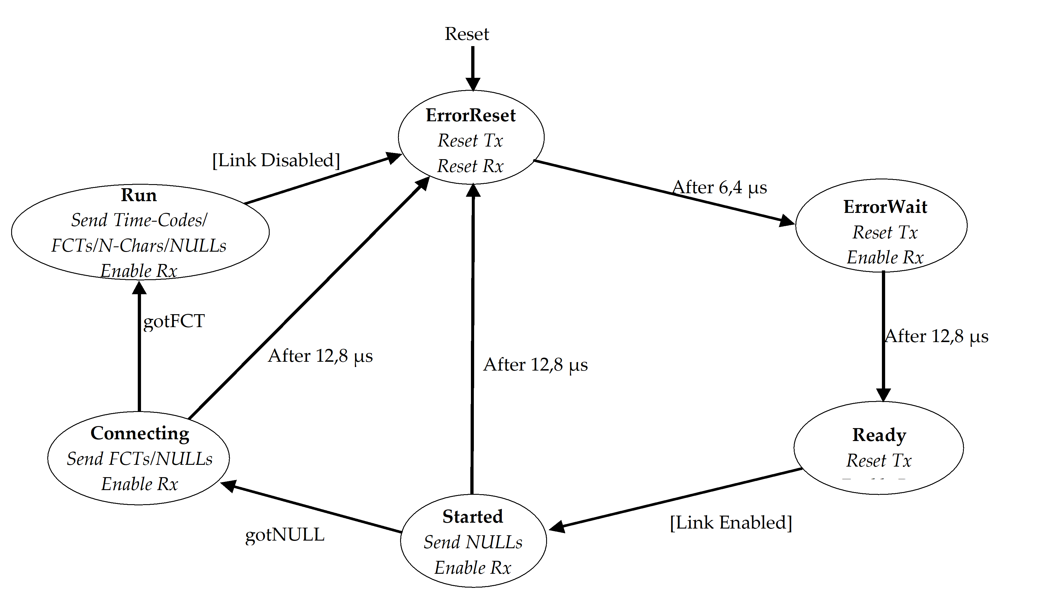 Figure 84: Basic state diagram for SpaceWire link interface
After a link interface (one end of a link) is reset, it enters the ErrorReset state where the transmitter and receiver are reset. The transmitter reset is a controlled reset, resulting first in the transmitter stopping transmission, followed by resetting of the Strobe signal and then the Data signal. This sequence avoids the simultaneous transition of both Data and Strobe signals.
The link interface remains in the ErrorReset state for approximately 6,4 s and then moves to the ErrorWait state. In the ErrorWait state the transmitter remains disabled, but the receiver is enabled so that it can begin searching for NULLs. `
The link interface remains in the ErrorWait state for 12,8 s and then moves into the Ready state. The 6,4 s delay from ErrorReset to ErrorWait and the 12,8 s delay from ErrorWait to Ready make sure that the receivers at both ends of a link are ready to receive characters before either end starts transmission.
The link interface can be enabled in many possible ways, for example by software command, automatically when the receiver detects a NULL, or the link can be permanently enabled (see clause 8.6). When a link interface is enabled the [LinkEnabled] condition becomes true. The link interface moves from the Ready state to the Started state as soon as the link is enabled.
In the Started state the link interface instructs the transmitter to start sending NULLs. It remains in this state until the receiver detects that a NULL is received over the link or until a connection timeout expires. The connection timeout is set to a nominal 12,8 s since this period is generated for the ErrorWait state timeout. If a NULL is received then the link interface moves to the Connecting state. If no NULL is received within 12,8 s it moves to the ErrorReset state. In the latter case the link interface goes through the reset sequence (ErrorReset, ErrorWait, Ready) and attempts to make a connection again a short time later.
In the Connecting state the link interface sends some FCTs (and NULLs) and waits for the reception of an FCT. If an FCT is received the link interface moves on to the Run state. If an FCT is not received within 12,8 s then link connection was not made properly, so the link interface moves back to the ErrorReset state. The link interface then goes through the reset sequence (ErrorReset, ErrorWait, Ready) and attempts to make a connection again a short time later.
When the link enters the Run state it starts normal operation, sending and receiving data and control characters. It remains in the Run state until the link is disabled. The link interface then moves through the reset sequence (ErrorReset, ErrorWait, Ready) and stays in the ready state until the link is enabled once more.
Table 81 and Figure 85 illustrate an example of an initialization sequence. Link interface A is at one end of the link and link interface B is at the other end.
A link only sends FCTs once it receives a NULL. So, when a link receives an FCT it knows that the link is connected in both directions. A NULL correlation (or any other method of synchronization through NULL detection) in the ErrorWait, Ready and Started states ensures proper character synchronization. The NULL or FCT handshake sequence ensures that the link is connected in both directions before normal link operation begins.
The time taken from a link being enabled in the Started state to normal operation in the Run state can be as little as the time taken to transfer two NULLs and an FCT. End A is enabled and sends a NULL. End B is autostart enabled when it receives the NULL from end A and sends a NULL followed by an FCT. End A receives the NULL from end B and sends an FCT. Both ends receive FCTs and move to the Run state. At a link data signalling rate of 10 Mb/s this can take just 2 s.
Table 81: Example of initialization sequence
|
Link interface end A
|
Link interface end B
|
Event or condition causing transition
|
|
ErrorReset
|
ErrorReset
|
End A times out after 6,4 s and moves to the ErrorWait state.
|
|
ErrorWait
|
ErrorReset
|
End B times out after 6,4 s and moves to the ErrorWait state.
|
|
ErrorWait
|
ErrorWait
|
End A times out after 12,8 s and moves to the Ready state.
|
|
Ready
|
ErrorWait
|
End A is link enabled so moves to the Started state.
|
|
Started
|
ErrorWait
|
End B detects NULL sent from end A. This is registered as gotNULL by end B. There is no state change.
|
|
Started
|
ErrorWait
|
End B times out after 12,8 s and moves to the Ready state.
|
|
Started
|
Ready
|
End B is link enabled so moves straight to the Started state.
|
|
Started
|
Started
|
End B sends a NULL. It has already detected a NULL (gotNULL) so can now move to the Connecting state.
|
|
Started
|
Connecting
|
End A detects NULL sent from end B (gotNULL) and can move to the Connecting state.
|
|
Connecting
|
Connecting
|
End A sends out FCTs (and NULLs).
|
|
Run
|
Connecting
|
End A sends out FCTs, NChars and NULLs.
|
|
Run
|
Run
|
Both ends are in the Run state and begin normal operation sending and receiving NChars, FCTs and NULLs.
|
Figure 85: Example of typical initialization sequence
Normal operation
In normal operation both ends of the link are in the Run state and are sending and receiving TimeCodes, FCTs, NChars and NULLs.
An example is a host system with buffer space sufficient to hold 16 NChars. This host system at one end of a link (end A) indicates that it is ready to receive NChars by twice flagging that it has room for 8 more characters to the link interface. The link interface sends two FCTs to the other end of the link (end B), which increments its credit count accordingly (from zero to 16). The link interface at end B indicates to its host system that it is ready to transmit data (NChars). When the host system at end B has data to transfer, it passes it to the link interface, which sends it across the link to end A. As each character is transmitted by the link interface (end B), it decrements its credit count until it reaches zero, at which point the link interface (end B) indicates to its host system that it is not ready to transfer any more data. The data received at end A is passed on to its host system, which places it in its 16 character buffer. As the host system uses the data out of this buffer it makes space for the reception of more data. As soon as there is space for another 8 more characters it flags this to the link interface, which then sends out another FCT informing end B that 8 more normal characters may be sent.
Error detection (normative)
General
Whenever one of the following errors occur both character synchronization and flowcontrol status shall cease to be valid: disconnect errors, parity errors, escape errors, credit errors and character sequence errors.
This are the five forms of receiver error that can be detected and acted upon at the exchange level.
The error detecting end shall be reset and reinitialized to recover character synchronization and flow control status.
This forces the remote end to do the same.
Empty packets, which can be received in addition to these errors, shall be discarded.
Handling receiver errors
Disconnect error
Overview
An operational link interface sends TimeCodes, FCTs, NChars or NULLs continuously, and thus the Data, Strobe or both signals are always changing.
Handling
The receiver shall detect a disconnection when the time interval from the last transition on either the Data or Strobe signal exceeds the disconnectdetection time.
The disconnectdetection time shall be 850 ns nominal.
See clause 8.11.2 for the disconnect timing specification. A disconnection cannot be detected unless the receiver has previously received at least one bit.
The detection of a disconnection shall provoke a disconnect error.
A disconnect error can either be caused when one end of the link is disabled or when the link is physically disconnected (intentionally or unintentionally).
If a physical disconnection is the cause of the disconnect error then both ends of the link shall try repeatedly to make a connection until the link is reconnected or until the link interfaces are disabled.
If a disconnect error is detected then the link interface shall follow the exchange of silence error recovery procedure described in clause 8.9.4.
If the disconnect error occurs in the Run state then the disconnect error shall be flagged up to the network level as a link error (see clause 8.9.5).
Parity error
When a parity bit is received it shall be checked (see clause 7.4).
If a parity error occurs after the first NULL is received, then the link interface shall follow the error recovery procedure described in clause 8.9.4.
If the parity error occurs in the Run state then the parity error shall be flagged up to the network level as a link error (see clause 8.9.5).
Escape error
An ESC character shall only be used to form either the NULL i.e. ESC followed by FCT, or the TimeCode, i.e. ESC followed by a single data character (see clause 7.3).
If a ESC character is received followed by any control character other than an FCT then the link interface shall follow the error recovery procedure described in clause 8.9.4.
If the escape error occurs in the Run state then the escape error shall be flagged up to the network level as a link error (see clause 8.9.5).
Credit error
A credit error shall be identified when in the Run state, a normal character is received when the host system is not expecting any NChars.
A credit error can be caused if an error occurs undetected by the parity bit (e.g. two bits in error) which results in one or more spurious FCTs.
In the event of a credit error the link interface shall follow the error recovery procedure described in clause 8.9.4.
If the credit error occurs in the Run state then the credit error shall be flagged up to the network level as a link error (see clause 8.9.5).
Character sequence error
Overview
During initialization it is possible for a link interface to receive FCTs or NChars when they are not expected. Any unexpected characters are caught by the exchangelevel state machine resulting in the link being reset and reinitialized (see Figure 84).
Handling
As a character sequence error can only occur during link initialization, it shall not be flagged up to the network level as a link error (see clause 8.9.5).
Handling empty packets
Overview
Empty packets, i.e. an EOP or EEP followed immediately by another EOP or EEP, are not expected, but they can occur if a packet terminated by an EEP comprises just the header and the EEP (see clause 11.4) and the header characters are stripped off as the packet progresses through a network leaving just the EOP (see clauses 10.1.2.7 and 10.2.3).
Handling
In the Run state, if the next NChar received after an EOP or EEP is received is another EOP or EEP, then the link interface may discard the second EOP or EEP (see clause 10.5.4.3).
This error shall not be flagged up to the network level as a link error (see clause 8.9.5).
In this way empty packets are discarded quietly.
Exchange of silence error recovery procedure
General
When one end of the link (end A) is disabled or detects an error, it ceases transmission. As described in clause 8.9.2.1, this causes a disconnect error at the other end of the link (end B). End B then ceases transmission, resulting in a disconnect error at end A. This procedure is known as an “exchange of silence” (see Figure 45).
Handling
After an exchange of silence, both ends of the link shall cycle through the reset sequence (ErrorReset, ErrorWait, Ready) ending up in the Ready state ready to begin operation once enabled, proceeding then as follows.
If both ends are enabled then they shall move to the Started state and reinitialize.
If one end (end A) is disabled and the other end (end B) is enabled then the following series of events shall continue until either end A is enabled or end B is disabled:
- end B, to move from the Ready state to the Started state, and send NULLs for 12,8 s.
- Since end A is disabled it cannot respond, but have started its disconnect timer and also have registered that a NULL was received.
- When end B completes the 12,8 s timeout, to move to the ErrorReset state and disconnect (stop its output).
- End A can detect the disconnection so end A to move also to the ErrorReset state.
- Both ends, to move once again through the reset sequence.
Reporting link errors to network level
Receiver errors (i.e. disconnect error, parity error, escape sequence error, character sequence error and credit error) during link initialization (i.e. ErrorReady, ErrorWait, Ready, Started and Connecting states) shall not be reported to the network level.
Once a link connection is established (Run state), a receiver error represents a failure of the link connection and shall be reported to the network level so that appropriate action for error recovery or reporting, as described in clause 10.5, can be taken.
A link error shall be reported to the network level whenever any of the following errors occur while a link interface is in the Run state: disconnect error, parity error, escape sequence error, or credit error.
The exclusion of character sequence error from this list is because a character sequence error can only occur during initialization.
Exception conditions
Overview
The following clauses describe the exception conditions where events do not follow the expected sequence.
Disconnect error while waiting to start
“Waiting to start” means that a link interface is in either the ErrorReset, ErrorWait, Ready or Started state. A disconnect error cannot be detected while waiting to start, unless the other end of the link (end B say) has sent at least one bit, so that the disconnect detect mechanism at end A can be activated. End B then gives up waiting for end A to send a NULL and moves to the ErrorReset state and stops its transmitter, thus causing the disconnect. An alternative possibility is that the link becomes physically disconnected. Table 82, Table 83, Table 84 and
Table 85 illustrate the various sequences of events starting from when end B has just moved to the ErrorReset state.
If a physical disconnection has occurred then both ends of the link continue to try to make a connection, cycling around the reset sequence, until they are disabled or until the connection is reestablished.
Table 82: End A in ErrorReset state
|
Link Interface end A
|
Link interface end B
|
Event or condition causing transition
|
|
ErrorReset
|
Started
|
End B times out while waiting to receive a NULL from end A or end B detects a disconnect. End B moves to the ErrorReset state.
|
|
ErrorReset
|
ErrorReset
|
End A and end B are both in the ErrorReset state. They then step through the reset sequence and start again when both ends are enabled.
|
Table 83: End A in ErrorWait state
|
Link interface end A
|
Link interface end B
|
Event or condition causing transition
|
|
ErrorWait
|
Started
|
End B times out while waiting to receive a NULL from end A or end B detects a disconnect. End B moves to the ErrorReset state.
|
|
ErrorWait
|
ErrorReset
|
End B stops transmission. This is detected at end A as a disconnect error. End A moves to the ErrorReset state.
|
|
ErrorReset
|
ErrorReset
|
Both ends step through the reset sequence and start again when both ends are enabled.
|
Table 84: End A in Ready state
|
Link interface end A
|
Link interface end B
|
Event or condition causing transition
|
|
Ready
|
Started
|
End B times out while waiting to receive a NULL from end A or end B detects a disconnect. End B moves to the ErrorReset state.
|
|
Ready
|
ErrorReset
|
End B stops transmission. This is detected at end A as a disconnect error. End A moves to the ErrorReset state.
|
|
ErrorReset
|
ErrorReset
|
Both ends step through the reset sequence and start again when both ends are enabled.
|
Table 85: End A in Started state
|
Link interface end A
|
Link interface end B
|
Event or condition causing transition
|
|
Started
|
Started
|
End B times out while waiting to receive a NULL from end A or end B detects a disconnect. End B moves to the ErrorReset state.
|
|
Started
|
ErrorReset
|
End B stops transmission. This is detected at end A as a disconnect error. End A moves to the ErrorReset state.
|
|
ErrorReset
|
ErrorReset
|
Both ends step through the reset sequence and start again when both ends are enabled.
|
Link connected in one direction but not in the other
A link can be connected in one direction and not in the other while a link is in the process of being plugged in or if there is a break in the link cable.
In this case events follow the sequence listed in the Table 86. For convenience it is assumed that both links are in the Started state and that end A is connected to end B, but end B is not connected to end A.
Table 86: Link connected in one direction (A to B) but not in other
|
Link interface end A
|
Link interface end B
|
Event or condition causing transition
|
|
Started
|
Started
|
End A is sending NULLs to end B and these are received, starting the disconnect timer of end B and registering as GotNULL at end B. End B moves therefore to the Connecting state.
|
|
Started
|
Connecting
|
End A is in the Started state waiting for NULLs to arrive. After waiting for 12,8 s end A times out and moves to the ErrorReset state.
|
|
ErrorReset
|
Connecting
|
End B continues to send NULLs and FCTs and is able to accept FCTs.
|
|
ErrorReset
|
ErrorReset
|
Both ends are in the ErrorReset state and they now cycle through the reset sequence (e.g. ErrorReset, ErrorWait, and Ready) until the link is properly connected or until one or both link interfaces are disabled.
|
Parity error while waiting to start
Parity errors are only recognized after a NULL is received. If a parity error occurs during link initialization the effect is identical to a disconnect error.
One end starts as other end disconnects
One end (end A) arrives at the Start state 12,8 s before the other end (end B) arrives at the Start state. The sequence of event is illustrated Table 87.
Table 87: One end starts as other end disconnects
|
Link interface end A
|
Link interface end B
|
Event or condition causing transition
|
|
Started
|
Ready
|
The timeout timer at end A expires (after 12,8 s) so end A moves to the ErrorReset state.
|
|
ErrorReset
|
Started
|
End B has already received a NULL from end A (gotNULL is TRUE) so moves straight on into the Connecting state.
|
|
ErrorReset
|
Connecting
|
End A stops transmitting and causes end B to detect a disconnect. End B then moves on into the ErrorReset state.
|
|
ErrorReset
|
ErrorReset
|
Both ends step through the reset sequence and start properly next time round.
|
D connected, S disconnected
If D is connected and S disconnected then the clock generated in the receiver follows the Data signal, i.e. there is a clock edge every time the Data signal changes. This results in a continuous sequence of 0101010101.
During initialization this sequence is ignored as it does not produce a NULL so initialization fails until the Strobe signal is properly connected. In this case the link interface cycles round ErrorReset, ErrorWait, Ready, Started until full link connection is achieved or until the link is disabled.
If S becomes disconnected after a NULL is received, this sequence produces a parity error for both control characters (4 bits) extracted from the 01010101010 sequence, but does not produce a parity error for data characters (10 bits).
If the disconnection occurs so that the 01010101010 sequence is regarded as control characters a parity error is detected and the link interface cycles through ErrorReset, ErrorWait, Ready and Started until S is connected or the link is disabled.
If the disconnection occurs so that the 010101010 sequence is regarded as data characters then no parity error is detected and the link interface receives a continuous series of data characters with the value AA hex (note that SpaceWire is least significant bit first).
S connected, D disconnected
If S is connected and D disconnected then the clock generated in the receiver follows the Strobe signal, i.e. there is a clock edge every time the Strobe signal changes. This results in a continuous sequence of 1111111111 since the Data signal input goes to 1 when the data line is disconnected. If the data line is shorted to ground then the continuous sequence 0000000000 is received.
During initialization either sequence is ignored as it does not produce a NULL so initialization fails until the Data signal is properly connected. In this case the link interface cycles round ErrorReset, ErrorWait, Ready, Started until full link connection is achieved or until the link is disabled.
If D becomes disconnected after a NULL is received the received data sequence quickly produces a parity error because the parity is even for both control characters (4 bits) and data characters (10 bits) extracted from the received sequence, whereas the expected parity is odd (see clause 7.4). The parity error causes the link interface to cycle through ErrorReset, ErrorWait, Ready and Started until D is connected or the link is disabled.
One side of differential pair disconnected
The effect of disconnecting one side of the differential pair depends upon the values of the internal bias resistors at the interface, on the length of cable and on the grounding arrangements. Three cases are possible:
The Data and Strobe signals are still received correctly but with a much reduced noise margin. The link then continues operating with a significant increase in the number of detected parity errors.
The Strobe signal sits at logic 0 or logic 1. This is similar in effect to the D connected, S disconnected case of clause 8.10.6
The Data signal sits at logic 0 or logic 1. This is similar in effect to the S connected, D disconnected case of clause 8.10.7.
Link timing (normative)
D and S reset timing
The delay between the reset of the Strobe signal and the Data signal shall be between 555 ns (i.e. the period of slowest permitted transmit clock, 2 MHz – 10 %) and the shortest clock cycle time for the transmitter (i.e. the period of maximum clock, dependent upon implementation).
Disconnect timing
The disconnect timeout of 850 ns nominal shall be from 727 ns (i.e. 8 cycles of 10 MHz + 10 % clock) to 1000 ns (i.e. 9 cycles of 10 MHz - 10 % clock).
Exchange timeout periods
The 6,4 s (nominal) timeout period shall be from 5,82 s (i.e. 64 cycles of 10 MHz + 10 % clock) to 7,22 s (i.e. 65 cycles of 10 MHz - 10 % clock).
The 12,8 s (nominal) timeout period shall be from 11,64 s (i.e. 128 cycles of 10 MHz + 10 % clock) to 14,33 s (i.e. 129 cycles of 10 MHz - 10 % clock).
System time distribution (normative)
Overview
As defined in clause 7.4, a TimeCode comprises the ESC character followed by a single 8bit data character. The data character contains two control flags and a sixbit timecount which can be the least significant six bits of system time.
Handling
Each node or router shall contain one sixbit time counter.
A single link interface shall manage the distribution of time.
The timemaster interface shall have a TICK_IN input, which is asserted periodically by its host system.
For example, every millisecond.
When the time master link interface receives a tick (TICK_IN asserted) it shall increment its timecounter and then send out a TimeCode with the sixbit time field of the data character set to the new value of the timecounter and the other two bits set to the value of the control flags.
The frequency at which the TICK_IN signal is driven is called the tick rate.
The TimeCode shall be sent out as soon as the current character or control code is transmitted.
TimeCodes shall not be sent out until a link interface is in the Run state
For the Run state, see clause 8.5.
When the link interface at the other end of the link receives the TimeCode, it shall update its associated timecounter with the new time and assert its TICK_OUT output signal and copy the values of the two control flags in the TimeCode to the controlflag outputs.
The new time should be one more than the timecounter’s previous timevalue.
This fact can be used for checking on TimeCode validity.
If a link interface receives a TimeCode that is equal to its current sixbit time value then it shall not emit a TICK_OUT output signal.
This prevents repeated TimeCode propagation in a circular network.
When a link interface on a router or node receives a TimeCode it shall check that it is one more (modulo 64) than its current time setting.
The router or node shall then increment the router’s timecount and emit a tick signal.
This tick signal propagates to all the output ports of the router so that they all emit the TimeCode. This TimeCode is the same value as that received by the router since the router timecounter has been incremented. If there is a circular connection then the router receives a TimeCode with the same time value as the router timecounter. The controlflags of the TimeCodes that are emitted are set to the control flag values of the received TimeCode that caused the subsequent emission of TimeCodes by the router.
If the router or node receives a TimeCode with the same time value as the router timecounter the TimeCode shall be ignored.
- 1 In this way, time flows forwards through a network reaching all nodes, but is suppressed if it flows backwards due to a circular connection.
- 2 With the provision of this basic timedistribution function, application level protocols can be used, for example, to distribute specific time values at full resolution (not just 6 bits) and to issue time dependent commands.
After reset or disconnectreconnect (state machine in ErrorReset state) the timecounter shall be set to zero and any controlflag outputs shall be set to zero.
If a received TimeCode is not one more than (modulo 64) or equal to the current timecount at the receiving link interface, then either the TimeCode or the timecount shall be considered invalid.
This can happen if a TimeCode is lost, or if a link is reset or restarted after a disconnect.
If the TimeCode is invalid then the timecount shall be updated to the new value but the tickoutput shall not be asserted.
- 1 This prevents propagation of invalid TimeCodes across a network. When the next TimeCode is received it is expected that the timecounter matches the TimeCode and normal operation resumes.
- 2 Nodes using the system time distribution function can either use the TICK_OUT signal as a periodic timing signal or use the value of the timecount as an indication of the least significant 6 bits of system time.
As a missing tick results in a timing discrepancy the following should be done: - The TICK_OUT signal not be used to increment a counter with the expectation that this counter corresponds to the system time.
- Rather a timelock or phaselock technique be used where a free running local timecounter is updated to be an exact multiple of the system tick rate every time the TICK_OUT signal is asserted.
- 1 The reason for this is that when using the TICK_OUT signal as a periodic timing signal the TimeCode can be missed so that a TICK_OUT signal is missed.
- 2 The accuracy with which system time can be distributed is dependant upon the number of links over which it is distributed and the operating rate of each of those links. A delay of at least 14 bitperiods (ESC + data character = (4 + 10) bits) is encountered for each link that the TimeCode traverses, due to the time taken for each link interface on the way to receive a TimeCode. This gives rise to a timeskew across a network of STskew = 14N/R, where N is the number of links traversed and R is the average link operating rate. Jitter is also introduced at each link interface due to the variation in time spent waiting for the transmitter to finish transmitting the current character or control code. At each link interface a delay of 0 bit periods to 10 bit periods can be encountered. Across a network, this gives rise to a total jitter of STjitter = 10N/R. For an average rate of 100 Mb/s and 10 links traversed, the time skew is 1,4 µs and the jitter 1,0 µs. The skew and jitter may be higher than indicated above depending on the implementation of the link interface. A time accuracy across a network of better than 10 µs can be difficult to achieve.
Packet level (normative)
Overview
The packet level protocol agrees with the principles of the DSSE and DSDE character level encoding given in clause 9 of the IEEE Standard 1355-1995 [1]. Some ambiguities in the IEEE Standard 1355-1995 are resolved in this Standard. See annex A for details of the differences between SpaceWire and IEEE Standard 1355-1995 and the reasons for the differences.
Packet composition
General
A packet shall comprise a destination address, a cargo and an end_of_packet (EOP or EEP) marker, i.e.
<destination address> <cargo> < end_of_packet >
Destination
The destination address shall consist of a list of zero or more destination identifiers (dest_id):
<destination address> = <dest_id1> <dest_id2> 0 <dest_idN>A destination identifier shall comprise one data character.
The destination identifier list shall not be delimited.
- 1 The case of zero destination identifiers in the destination list (i.e. the destination list is empty) is intended to support a network which is simply a single pointtopoint link from source to destination.
- 2 The case of one or more destination identifiers in the destination list is intended to support routing of a packet across a network.
Cargo
The cargo shall comprise the data characters that are to transfer from the source to the destination.
The cargo shall contain one or more characters.
Clause 8.9.3 describes what happens to empty packets.
Empty cargoes shall be allowed to move across the network.
A cargo can become empty if there is an error on the link.
End_of_Packet markers
There shall be two possible end_of_packet markers: EOP and EEP.
The EOP and EEP control character formats are described in clause 7.3 of this Standard.
EOP (end_of_packet) shall be used as the normal end of packet marker indicating the end of a packet.
EEP (error end_of_packet) shall be used to indicate the end of a packet in which an error occurs. The data in this packet can be valid, but the packet shall be prematurely terminated at the point that the error occurred.
The first data character following either end_of_packet marker shall be taken as the first character of the next packet.
NChar interleaving
NChars from one packet shall not be interleaved with NChars from another packet.
NChars can be interleaved with FCTs, NULLs and TimeCodes as explained in 8.3s.
Network level
Overview
Purpose
This clause describes the network level. First the basic concepts are described and then the SpaceWire routing switches, nodes and networks are defined. Network level errors are described and the network level error recovery protocol is defined.
Network and routing concepts
Purpose
In this clause the basic concepts of packet routing networks that apply to SpaceWire networks are introduced.
Networks
A network is made up of a number of links, nodes and routing switches. The nodes are the sources and destinations of packets. For example, a processor is a type of network node.
Links provide the means for passing packets from one node to another.
Nodes can be either directly connected by links or connected via routing switches. Usually a node can only support a few links (e.g. six links) and so can only be directly connected to a limited number of other nodes (e.g. six other nodes).
Routing switches connect together many nodes and provide a means of routing packets from one node to one of many other possible nodes.
An example network comprising several nodes and routing switches is illustrated in Figure 101. This figure is for illustrative purposes and does not show a practical network. Packets can be transferred from one node to another through one or more routing switches, or directly from node to node where direct connections exist.
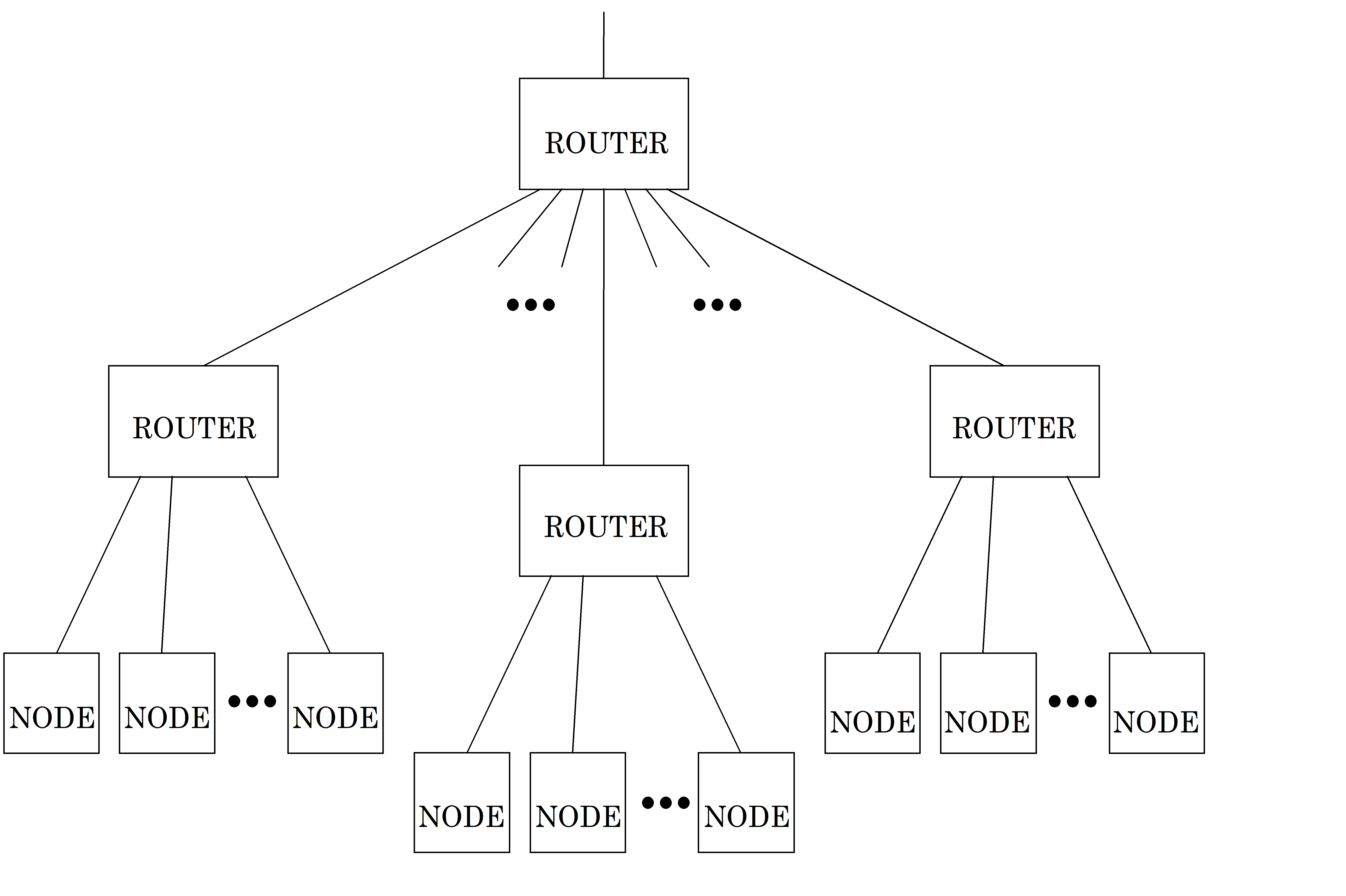 Figure 101: An example network
There are two types of routing switch: static and dynamic. A static routing switch sets up connections between nodes and does not change them very often. Dynamic switches change the routing frequently, usually on a packet by packet basis, and are consequently also known as packet routing switches. SpaceWire routing switches are dynamic, packet routing switches. Packets can be interleaved across data links and routing switches to provide many virtual communication channels across a few physical data links.
Packets
Data are split into packets so that it can be transported in manageable chunks across a network. Packets of data are the smallest elements of data that are handled at the network level. Packets are regarded as indivisible by the network level and are transported whole across a network.
SpaceWire packets have a simple packet structure (see clause 9):
Destination: the address of the destination node or task.
Cargo: the data to deliver.
End_of_Packet marker: a special character which indicates the end of a packet.
Flow control
Flow control is used to manage the movement of packets across a link connecting a node or a router to another node or router. A node or router accepts data only when buffer space for that data is available in the receiving node or router. When the receivebuffer becomes full the receiver stops the transmitting node from sending any more data.
SpaceWire uses flow control tokens to manage the flow of data across a link connecting one node or router to the next node or router (see clause 8.3).
Wormhole routing
Wormhole routing is a particular form of packet routing. Each packet contains a header which holds the destination node address either as the route through the network or as the identity of the destination node. As soon as the header for a packet is received the switch determines the output port to route the packet to by checking the destination address. If the requested output port is free then the packet is routed immediately to that output port. That output port is now marked as busy until the last character of the packet has passed through the switch – indicated by the end of packet marker being detected by the switch. Wormhole routing cuts down on the amount of buffering used within each switch, compared to a store and forward technique where an entire packet is first received and stored before it is sent out of the switch.
Wormhole routing is illustrated in Figure 102 which shows a packet being sent from one node to another through a routing switch (router). The header of the packet is marked as black and the rest of the packet as grey. As soon as the router receives the header it checks the requested output port. If the output port is free then the router makes a connection between the input port and the output port. The packet then flows through the router. When the end_of_packet (EOP or EEP) marker is received by the switch the router terminates the connection and frees the output port for its next packet which can come from any input port.
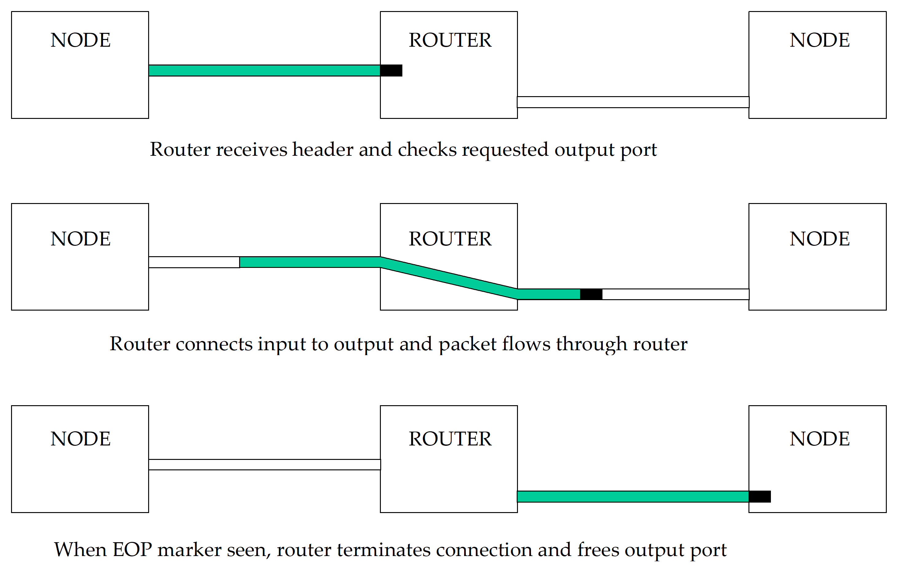 Figure 102: Wormhole routing
If a requested output port is busy then the input port halts the incoming packet until the output port becomes free. This is achieved by the input port ceasing to send flow control tokens to the source node. The link connecting the source node to the routing switch is then blocked until the routing switch output finishes transferring its current packet and becomes free to transmit the new packet.
Cascading
Direct connection between nodes can be used to interconnect a limited number of nodes (e.g. six nodes). A single routing switch can usually connect many more nodes depending on the size of the switch (e.g. 32 nodes). When larger networks are used, several switches can be cascaded to form larger networks (see Figure 101). So, to arrive at its destination a packet can travel through several switches.
Header deletion
Header deletion is a simple and effective technique designed to manage the transfer of packets across an arbitrary sized network. Header deletion is illustrated in Figure 103. The first header data character (destination identifier) of a packet is used to specify the router output port address. When a packet is received at a routing switch its first destination identifier is checked to determine the output port to route the packet through. The first destination identifier of the header is then deleted and the packet passes through the switch without this first destination identifier. The second destination identifier of the original header (now the first destination identifier) is used for any subsequent routing.
Figure 104 shows a packet passing through two routing switches. The destination address of the packet comprises three destination identifiers. At the first router the first destination identifier is used to determine the requested output port. This destination identifier is then stripped off. At the second router the second destination identifier is used and stripped off. Finally the packet arrives at the destination node with the third destination identifier at the front of the packet. This can be used to determine where the packet is to go within the destination node (see clause 10.1.2.8).
At each stage as the packet passes though the network, it can be regarded as a packet comprising a single destination identifier header, a cargo and an end of packet marker. When, at the first router this single destination identifier header is stripped off, the first data character of the cargo becomes the new destination identifier header. All stages treat the packet in the same way, using the first destination identifier to determine the destination (output port) and then deleting that first destination identifier before forwarding the packet.
Header deletion can be implemented in all routers in a network or at some selected routing devices only. The latter case cannot be performed appropriately by the router unless information is made available to it beforehand specifying the node addresses for which header deletion is applied (see clause 10.2.3 for requirements on this subject).
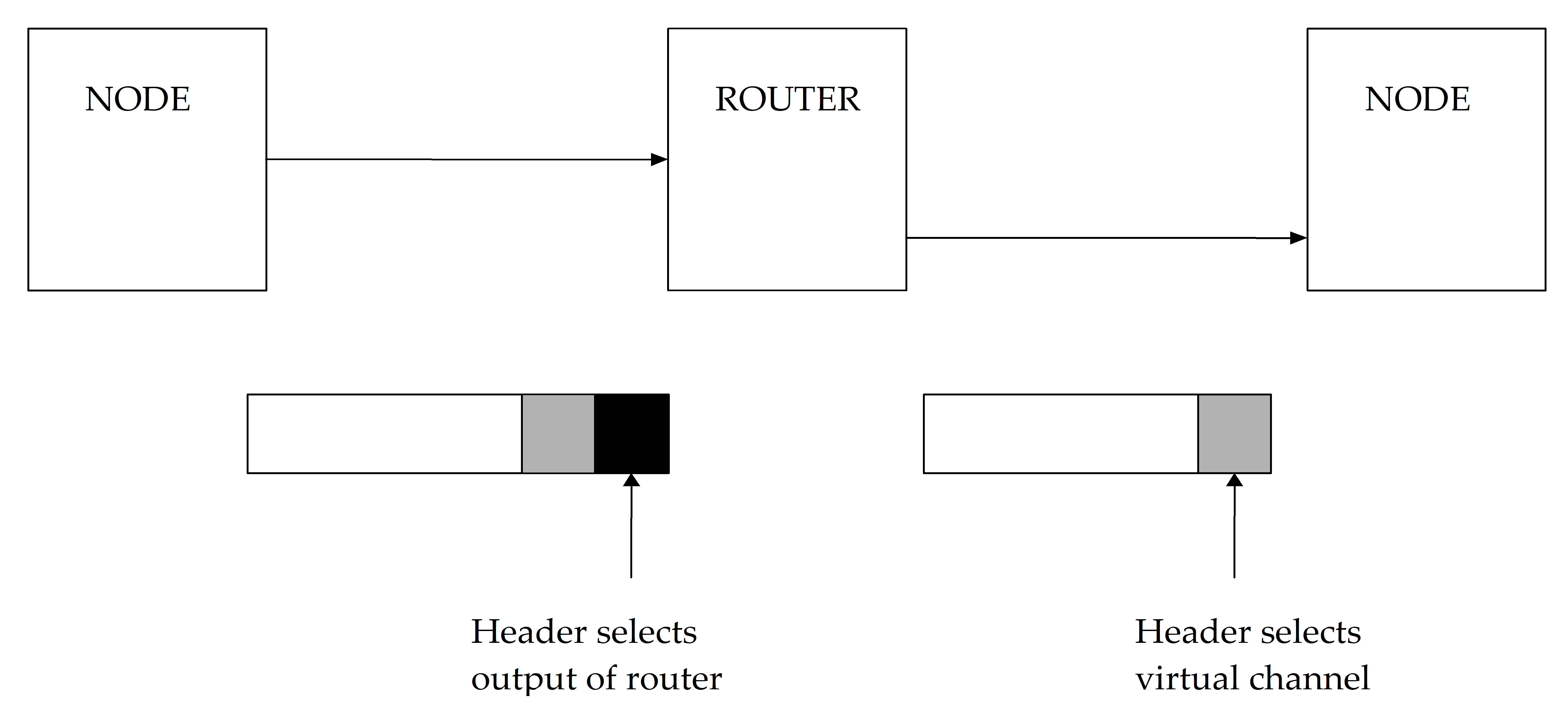 Figure 103: Header deletion
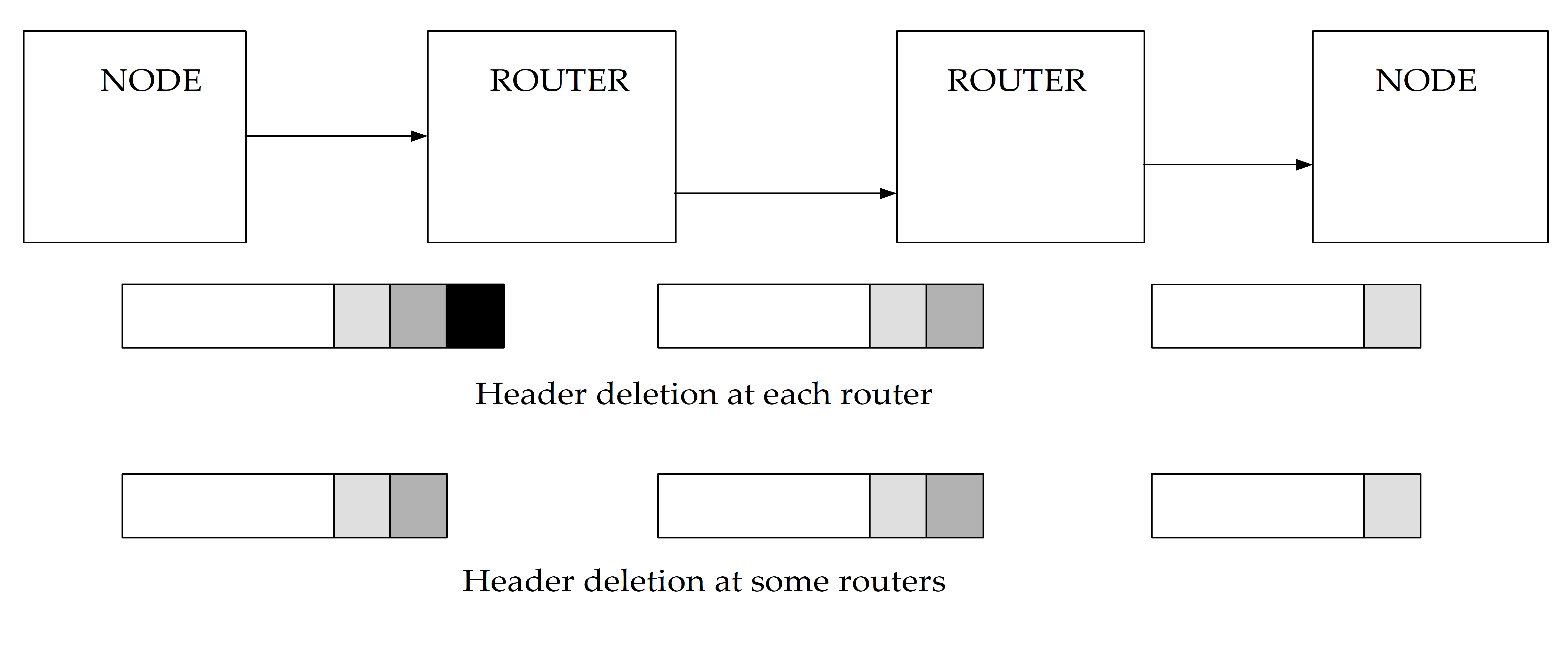 Figure 104: Header deletion across multiple switches
Virtual channels
Many packets from different sources and going to different destinations can be routed through a single data link. Each sourcedestination pair forms a virtual channel which is mapped on to the physical network comprising links and routing switches.
This concept can be extended within the source and destination nodes. An example is a processing device attached to a network. There can be several tasks running on the processor. These tasks can send or receive information to or from other tasks running on other processors within the network. When a packet arrives at a destination node its header (first data character) can be inspected to see what task it is intended for. The header is stripped off and the packet put in a buffer which can be accessed by the destination task.
Packet addressing
Purpose
In this clause several different packetaddressing schemes are considered and compared.
Path addressing
With path addressing the destination address is specified as a sequence of router output port numbers used to guide the packet across the network.
Path addressing is simple and uses comparatively few gates for implementation. Its drawback is that the destination address can become relatively large if several routing switches are traversed. Also the length of the destination address can vary depending on where the destination is located on the network relative to the source. The complexity of packet addressing is handled by the source node and the routing switches are comparatively simple.
Logical addressing
In logical addressing each destination has a unique number or logical address associated with it. These numbers can be assigned arbitrarily to nodes provided that no two nodes have the same logical address. When a source node transfers a message to a destination node it simply addresses the packet with the logical address. To support logical addressing each routing switch is provided with a routing table. This tells the router the output port to transfer a packet to, for each possible logical address. Figure 105 illustrates an example of a routing table.
|
Routing table
| |
|
Logical destination
|
Physical output port
|
|
1
|
8
|
|
2
|
1
|
|
3
|
3
|
|
4
|
1
|
|
…
|
…
|
Figure 105: Example routing table
In this example, when a packet is received with a logical address of 1 it is routed to output port 8 of the router. A packet with logical address of either 2 or 4 is routed to output port 1 and a packet with logical address 3 is routed to output port 3.
For a reasonable sized network the routing table can become fairly large. Initialization of the routing table can be done in several ways, for example using separate control or configuration links. With logical addressing the complexity of packet addressing is handled by the routing switches rather than by the source node, as is the case with path addressing.
Regional logical addressing
Logical addressing can be used in conjunction with header deletion. In this case the routing table also holds information about the headers to delete or to keep, for each logical address. This facilitates multiple level logical addressing schemes. For local addresses a single logical address is used whereas to send a packet to more remote locations a double logical address is used (or more logical addresses as appropriate for the network). In the latter case the first logical address represents the route from one region to the destination region and the second logical address represents the local address within the destination region. When the packet arrives at the destination region the routing switch that transfers the packet to the destination region strips off the first logical address making the local address visible for subsequent local routing.
Regional logical addressing can reduce the size of the routing switches used for logical addressing at the expense of a slightly longer address (two or more data characters), when packets are for transmission to logical addresses in remote regions.
Interval labelling
Interval labelling is based on logical addressing. Destinations are grouped together in contiguous intervals, e.g. 13, 49, 1032. Each interval is assigned to an output port of the routing switch so that, following the example, destinations 13 are all reached via one particular output port. Interval labelling was designed to reduce the size of the routing tables and to speed up the time taken to decode the destination address within a routing switch.
Interval labelling is more complex than logical addressing, but uses smaller routing tables.
Group adaptive routing
Group adaptive routing is a means of routing packets to a requested destination over different paths through a network. This is illustrated in Figure 106.
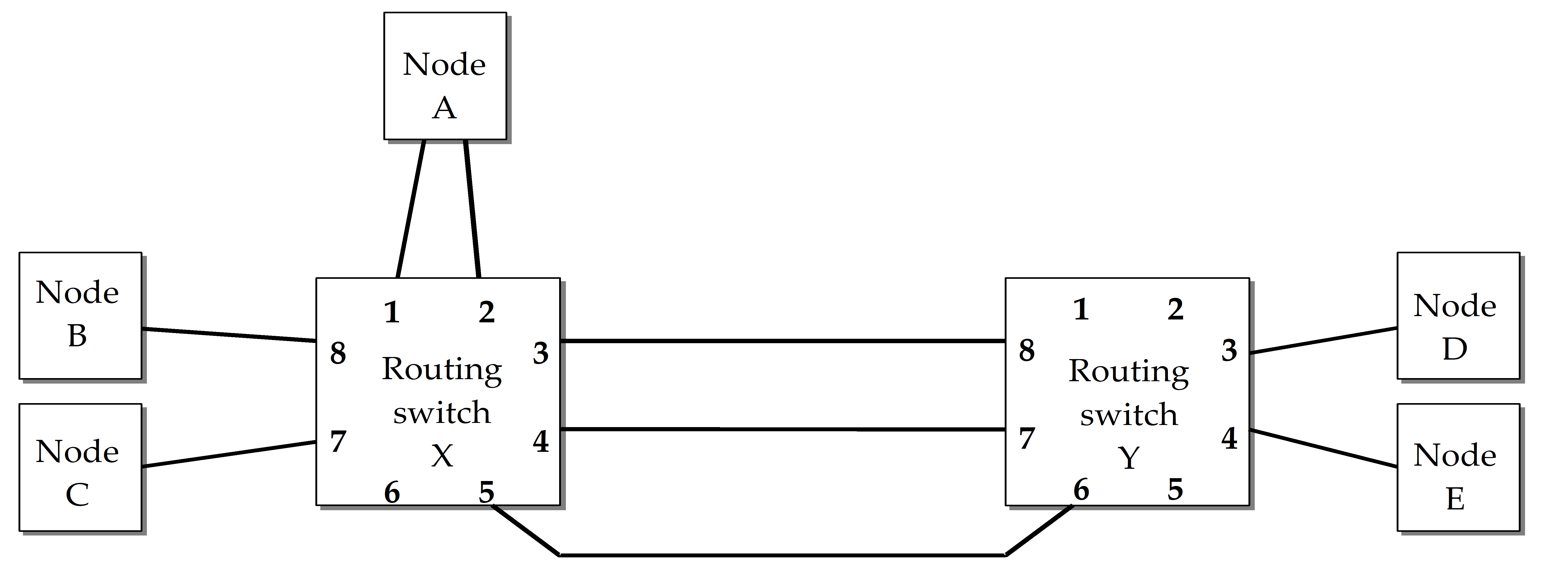 Figure 106: Group adaptive routing
Assume that node B wants to send a packet to node D and that logical addressing is being used. The packet is sent and subsequently arrives at routing switch X. The routing table inside routing switch X indicates output port 3 as output port to route the packet. Output port 3 is currently busy sending another packet, so the packet is stalled and remains waiting until output port 3 becomes free before it can move on.
There are three links that run from routing switch X to routing switch Y. Any of these three links that is free can be used to send the packet. Rerouting a packet out of one of several possible equivalent output ports is known as Group adaptive routing. Links that connect to the same destination (node or routing switch) are called a group. Any link in a group can be used to transfer data to their destination.
Group adaptive routing is an effective means of controlling allocation of link bandwidth, making sure that efficient use is made of the available network resources.
Group adaptive routing can be implemented relying on the configuration registers to hold information about equivalent output ports. When a packet is received it can be routed to any of the equivalent output ports that are currently free, or to whichever port become available first. Assignment of a packet to an output port involves also the consideration of any arbitration scheme that is implemented within the routing switch. In the event of several packets competing for a set of links, clause 10.2.5 specifies the means of arbitration when an output port becomes available, giving access to the newly freed output port to the packet with the highest priority destination address.
SpaceWire routing switches (normative)
Purpose
This clause defines SpaceWire routing switches.
Routing switch
A SpaceWire routing switch shall comprise a number of SpaceWire link interfaces (encoderdecoders) and a routing matrix.
The routing matrix enables the transfer of packets arriving at one link interface to another link interface on the routing switch, and the sending out from this link. Each link interface can be considered as comprising an input port (the link interface receiver) and an output port (the link interface transmitter).
A SpaceWire routing switch shall transfer packets from the input port of the switch where the packet arrives, to a particular output port determined by the packet destination address.
The destination address can comprise several data characters (see clause 9.2.2).
Routing scheme
A routing switch shall use the leading data character of a packet to determine the output port of the routing switch to route the packet.
The leading data character is the very first data character sent over a link or the first data character following the EOP or EEP that terminated the previous packet.
A SpaceWire routing switch shall either implement only path addressing, or a combination of path addressing, logical addressing and regional addressing.
A routing table within the routing switch shall hold the logicalphysical mapping and shall determine whether header deletion is applied (i.e. when a particular physical outputport represents a gateway between distinct regions).
The routing switch addresses shall be assigned as shown in Table 101.
- 1 A leading data character with a value of 0 results in the packet being routed to the routing switch configuration logic.
- 2 A leading data character with a value of 6 results in the packet being routed to output port 6.
- 3 A leading data character with a value of 49 results in the packet being routed to the output port that is referred to in location 49 of the routing table within the routing switch.
A NULL routing table entry shall mean that the routing table entry is undefined and if referenced shall lead to an invalid address error
See clause 10.5.4.
Path addressing shall be limited to 32 ports maximum (including the configuration port).
Routing switches with less than this maximum number may be used.
Accessing an output port that does not exist shall result in an invalid address error
See clause 10.5.4.
Logical addressing shall be limited to 224 logical addresses.
Regional addressing shall be used for larger networks with each cluster limited to a maximum of 224 logical addresses.
Regions using logical addressing can be connected to regions using path addressing.
Configuration ports shall be accessed using path addressing only.
A routing table cannot address the internal configuration port (address 0).
Header deletion shall always be applied to path addresses.
If header deletion applies then the leading data character (destination identifier) of each packet shall be deleted.
One and only one data character (destination identifier) shall be deleted by each routing switch with header deletion enabled, that is traversed by the packet.
For very large switches the two leading destination identifiers can be used by a single routing switch to determine the destination address This enables switches with up to 961 (31 31) physical links and with over 50,000 (224 224) logical addresses.
Logical address 255 is reserved for future use and should not be used.
Logical address 255 shall be treated in the same way as any other logical address.
Table 101: Routing switch addresses
|
Address range
|
Function
|
Header deletion
|
|
0
|
Internal configuration port
|
YES
|
|
131 (011F hex)
|
Physical output ports
|
YES
|
|
32-254 (20FE hex)
|
Logical addresses, which are mapped on to the physical output ports.
|
Optional on each output port. Header deleted if the physical output port is a gateway between distinct regions. Header can also be deleted on final link to a node.
|
|
255 (FF hex)
|
Reserved logical address, which is mapped on to physical output port. Treated in the same way as any other logical address (refer to 10.3.3 o.), but is reserved for future use (refer to 10.3.3 n.).
|
Optional on each output port. Header deleted if the physical output port is a gateway between distinct regions. Header can also be deleted on final link to a node.
|
Implementation of wormhole routing within SpaceWire routing switches
When a packet arrives at a routing switch the assigned output port shall be determined.
If the output port is free, i.e. not currently transmitting a packet, then the output port shall be allocated to transmit the newly arrived packet.
As each character of the packet arrives at the input port it shall be transferred immediately to the output port for transmission.
The output port shall not transmit any other packet until the packet that it is currently transmitting is sent or terminated following an error.
If the input port is waiting for packet characters to arrive then the output port shall also wait.
If the output port is waiting to transmit packet characters then the input port shall also wait.
If the assigned output port is busy then the newly arrived packet shall wait at the input port until the assigned output port is free to transmit the new packet.
When the output port finishes transmission of its current packet then it shall be available to accept a packet from another input port.
Arbitration
Two or more input ports can all be waiting to send data out of the same output port: SpaceWire routing switches shall provide a means of arbitrating between input ports requesting the same output port.
Priority based, roundrobin or random arbitration schemes can be implemented.
When the assigned output port becomes free the input port selected through arbitration shall transfer one packet to the output port.
An output port that has several input ports waiting to use it shall perform arbitration after the current packet is transmitted.
Clause 10.5.4 explains what happens if the destination address is invalid, i.e. not recognized by the routing switch.
Group adaptive routing
SpaceWire routing switches shall implement group adaptive routing for logical addresses and regional addresses.
SpaceWire routing switches can implement group adaptive routing for path addresses.
Group adaptive routing shall follow any arbitration scheme implemented within a routing switch.
The arbitration shall apply to all output ports within a group.
Packet distribution, broadcast and multicast
Overview
SpaceWire routing switches can implement packet distribution where data arriving at an input port is sent out of several output ports simultaneously.
Packet distribution is a restricted form of broadcast or multicast. The restriction is that a routing switch only distributes packets to output ports connected to nodes. This restriction is applied through use of appropriate network architectures and corresponding configuration of the routing switches in the network (see clause 10.4).
General broadcast or multicast implemented by a routing switch can give rise to system level problems when broadcast or multicast packets cycle round a circularly connected network indefinitely, resulting in a blocked network.
Broadcast and multicast can be implemented at a higher level by sending a packet to all (broadcast) or several (multicast) nodes on a network, one after the other.
Handling
Configuration registers within routing switches that implement packet distribution shall be used to specify the output ports to send packets.
The reset state of routing switches that implement packet distribution shall disable all packet distribution.
SpaceWire nodes (normative)
A SpaceWire node shall comprise one or more SpaceWire link interfaces (encoderdecoders) and an interface to the host system.
A SpaceWire node represents an interface between a SpaceWire network and an application system using the network services.
A SpaceWire node shall accept a stream of packets from the host system for transmission or provide a stream of packets to the host system after reception from the SpaceWire link, or do both.
SpaceWire network (normative)
A SpaceWire network shall comprise two or more SpaceWire nodes and zero or more SpaceWire routing switches.
SpaceWire nodes and SpaceWire routing switches shall be interconnected with SpaceWire links.
Packets shall be transferred from one SpaceWire node to another across SpaceWire links and through SpaceWire routing switches.
When packet distribution is used only output ports connected to nodes shall be used to forward the packets.
For packet distribution, see clause 10.2.7.
Network level error recovery (normative)
Overview: types of errors at packet level
The following types of error can occur at the packet level:
Link error, i.e. error detected at exchange level (see clause 8.9.5),
EEP received,
Invalid destination address.
Link error recovery
When a link error is detected within a link interface the following actions shall be taken at the network level to recover from the error.
If the error is detected at a source or destination node then the error shall be flagged up to the application level.
- 1 If the error is detected within a routing switch, then the error may be flagged to a pin on the routing switch device or to an internal status register within the routing switch.
- 2 Flagging to an external pin or internal status register can be useful for system debugging and monitoring.
The current packet being transmitted shall stop being transmitted, i.e. the part of the packet that is not yet transmitted shall not be transmitted, and therefore NChars up to and including the next EOP or EEP, shall be discarded by the link interface without being transmitted.
This is known as spilling the packet.
The current packet being received shall stop being received and the part of the packet that has been received already shall be terminated by an EEP.
If a complete packet has just been received when the error occurs, i.e. last character received before error was an EOP or EEP, then the link interface needs not add an EEP to the receive buffer, but one may be added.
In the following two cases the link shall not restart after an error until some NChars are read out of the receive buffer (to make room for at least 9 NChars):
- If the receiver buffer (e.g. FIFO) is full the EEP can be unable to be written into the receive buffer.
- If there is not room for at least 9 NChars (the EEP and 8 other NChars) then the link interface is not able to send an FCT.
This is a better solution than automatically starting after an error when the receive buffer remains full, because the link sends a few NChars and then become blocked again. If this happens, the link repeatedly blocks part of the network.
Since packets terminated by an EEP can flow through routing switches within a network (see clause 9.2.3), when an EEP is received at a destination node the application level shall be informed of the occurrence of the error indicated by the EEP.
- 1 The application level at a source node can resend the packet which was being sent when the link error was reported. The application level at a destination node can discard a packet terminated by an EEP, or can decide to use it.
- 2 Because the remainder of a packet is discarded after an error, very large packets can cause the link to halt for a long period of time while the packet is spilt. To bear this in mind is of particular importance when determining the size of packets to use in a particular application.
EEP received
Overview
An EEP at the end of a packet means that an error occurred within the transmitted packet and that the packet was consequently terminated prematurely. The data in the packet can be valid but the complete packet has not been transferred successfully.
If an EEP is received the action taken depends on whether the link interface is within a sourcedestination node or within a network routing switch, as described in the following clauses.
Routing switch
An EEP received by a routing switch shall be transferred through the routing switch in the same way as an EOP, i.e. EEP shall be treated in the same way as an EOP within routing switches.
Node
An EEP received by a link interface within a destination node shall be reported to the application level.
Invalid destination address
General
A logical address whose routing table entry refers to a nonexistent output port shall be regarded as an invalid address.
A destination address can be unrecognisable by a routing switch or node. For example, when a path address of 9 is specified in a routing switch with only eight output ports. A NULL logical address in a routing switch means that the location in the routing table is not configured, so is invalid.
Routing Switch
If a packet arriving at a routing switch has an invalid destination address then that packet shall be discarded (spilt) and the NChars arriving at the input port where the invalid destination address was detected be discarded until and including the next EOP or EEP.
The invalid destination address error may be flagged either to external status pins on the routing switch device or to a status register within the routing switch.
Node
If a packet arrives at a node with an unexpected destination address then that packet shall be discarded.
- 1 Whether a particular address is expected or not within a node depends upon the host system and its use of virtual channels.
- 2 The unexpected destination address may be flagged to the host system.
Double EOP or EEP
A routing switch receiving an empty packet shall discard it by deleting the second EOP or EEP.
An EOP or EEP received immediately after an EOP or EEP represents an empty packet which does not have a destination address.
Example networks
Overview
Several examples are provided in this clause to clarify the operation of packet routing and header deletion.
A SpaceWire network is illustrated in Figure 107. The SpaceWire nodes are numbered N1 to N9 and each has just one SpaceWire link interface. The SpaceWire routing switches are numbered R1 to R4 and each has four link interfaces.
 Figure 107: Example SpaceWire network
Path addressing
To transfer a cargo from node N1 to node N3 using path addressing the following packet is sent:
<3><cargo><EOP>
To transfer a cargo from node N1 to node N8 using path addressing the following packet is sent:
<4><3><2><cargo><EOP>
Logical addressing
To transfer a cargo from node N1 to node N3 using logical addressing the following packet is sent:
<43><cargo><EOP>
To transfer a cargo from node N1 to node N8 using logical addressing the following packet is sent:
<163><cargo><EOP>
The routing table contents are shown for each routing switch in Figure 108.
|
Routing table switch 1
|
|
Routing table switch 2
|
|
Routing table switch 3
|
|
Routing table switch 4
| ||||
|
…
|
|
|
…
|
|
|
…
|
|
|
…
|
|
|
41
|
1
|
|
41
|
4
|
|
41
|
4
|
|
41
|
`1
|
|
42
|
2
|
|
42
|
4
|
|
42
|
4
|
|
42
|
1
|
|
43
|
3
|
|
43
|
4
|
|
43
|
4
|
|
43
|
1
|
|
…
|
|
|
…
|
|
|
…
|
|
|
…
|
|
|
129
|
4
|
|
129
|
1
|
|
129
|
4
|
|
129
|
2
|
|
130
|
4
|
|
130
|
2
|
|
130
|
4
|
|
130
|
2
|
|
131
|
4
|
|
131
|
3
|
|
131
|
4
|
|
131
|
2
|
|
…
|
|
|
…
|
|
|
…
|
|
|
…
|
|
|
162
|
4
|
|
162
|
4
|
|
162
|
3
|
|
162
|
3
|
|
163
|
4
|
|
163
|
4
|
|
163
|
2
|
|
163
|
3
|
|
164
|
4
|
|
164
|
4
|
|
164
|
1
|
|
164
|
3
|
Figure 108: Example SpaceWire network routing table contents
Regional addressing
In this clause the SpaceWire network shown in Figure 107 is altered slightly to illustrate regional logical addressing i.e. logical addressing with header deletion on output ports that drive links between two regions. The altered SpaceWire network is shown in Figure 109. The network is split into two regions. The nodes in region 2 are renumbered to support the example, but the local logical address of each node is the same as before. The structure of the network is identical to that in Figure 109. A single data character is used to define the logical address within a region. Up to 224 nodes can be addressed within a single region. Some logical addresses within a region are used as the bridge (or route) to other regions. An unlimited number of regions can be supported.
To transfer a cargo from node N1 to node N3 (both in region 1) the following packet is sent:
<43><cargo><EOP>
To transfer a cargo from node N1 to node N5 (both in region 1) the following packet is sent:
<130><cargo><EOP>
To transfer a cargo from node N1 (region 1) to node N3 (region 2) the following packet is sent:
<109><162><cargo><EOP>
<109> is the logical address given to the link between region 1 and region 2 (R4 port 3 to R3 port 4). R4 deletes the header character on any packet leaving via port 3 or port 4. R3 deletes the header character on any packet leaving via port 4.
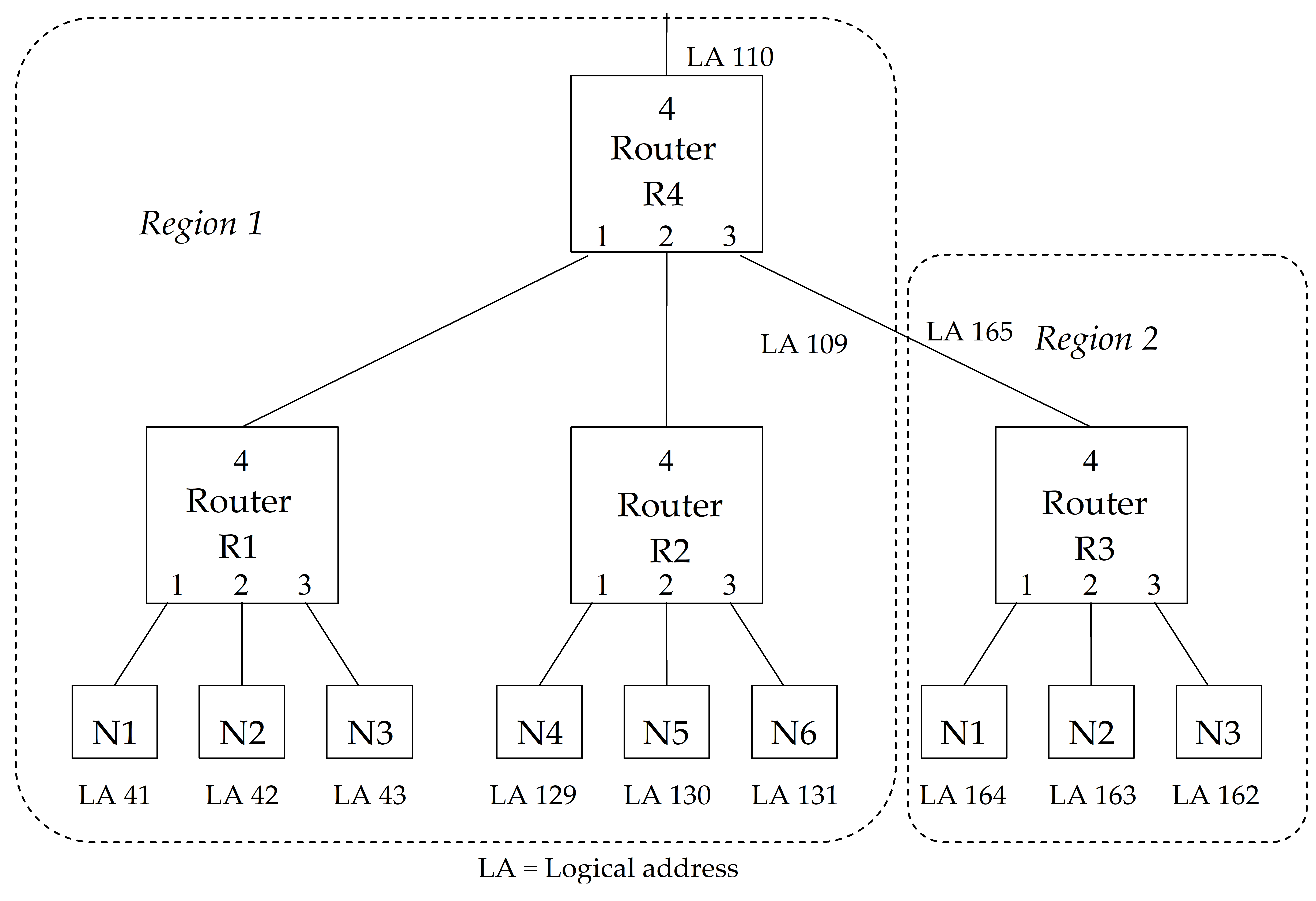 Figure 109: Example SpaceWire network with local logical address regions
Error recovery scheme
Purpose
The error recovery scheme is split across the exchange level and network level. This clause aims to describe the error recovery scheme as a whole, to aid comprehension.
Exchange level errors
The following errors (see clause 8.9) can be reported at the exchange level:
Disconnect error,
Parity error,
Escape sequence error,
Character sequence error,
Credit error.
The response to any of these errors is as follows:
Detect error,
Disconnect link,
Report error to network level,
Attempt to reconnect link if link interface still enabled.
Network level errors
General
The following errors (see clause 10.5) can be reported at the network level:
Link error (exchange level error),
EEP received,
Invalid destination address.
Link error
If a link error, i.e. error detected in exchange level, is reported to the network level then the network level responds as follows:
Error reported to network level.
Terminate current receive packet with EEP.
Spill current transmit packet until and including next EOP (or EEP).
If the error occurs in a link interface within a source or destination node then flag the error to the application layer.
If the error occurs in a link interface within a routing switch, then the error may be flagged to external status pins on the routing switch device or to a status register within the device.
This sequence of events is illustrated and described in more detail in clause 11.4.
EEP received
If an EEP is received the action taken depends on whether the link interface is within a destination node or within a network routing switch. In a destination node, the reception of an EEP is flagged to the application level. The packet terminated by the EEP is otherwise transferred as normal to the application level. In a routing switch no special action is taken when an EEP is received. The EEP is treated in exactly the same way as an EOP.
Invalid destination address
A packet that arrives at a routing switch with an invalid address, i.e. an address that is not recognized by the routing switch, is discarded.
Link error recovery
If any form of error is detected within the link interface then the following sequence of events occurs to recover from the error (see Figure 111):
Detect error (disconnect, parity, escape sequence, character sequence, credit).
Disconnect link.
If previous character was NOT EOP then add EEP (error end of packet) to the receiver buffer (i.e. the receive FIFO in Figure 111).
Delete data in the transmitter buffer (i.e. transmit FIFO in Figure 111) until the next EOP (End of Packet).
Reconnect.
Send next packet.
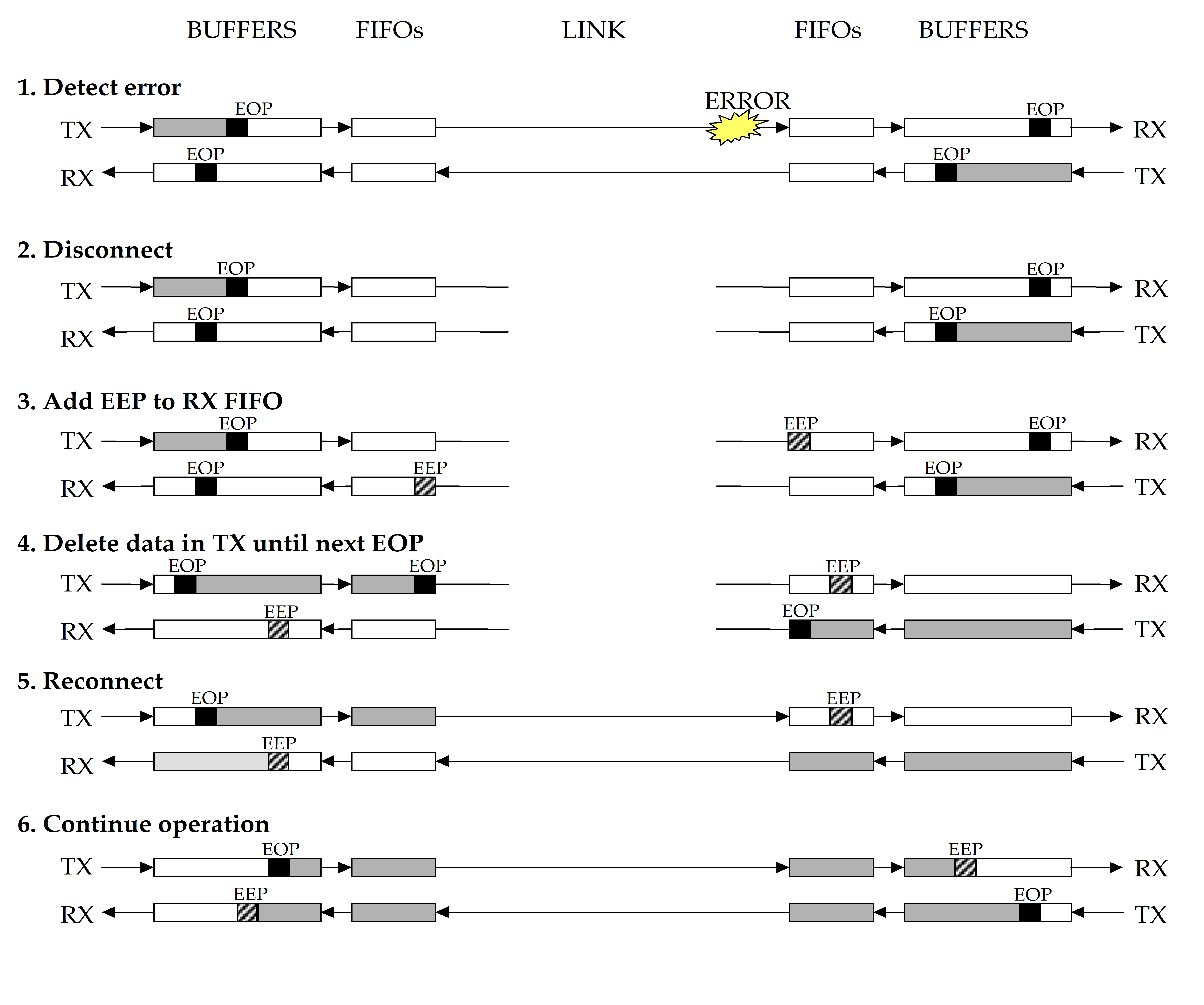 Figure 111: Link interface error detection and recovery operation
Figure 111 shows transmit and receive buffers and FIFOs. The reason for this is to illustrate a typical host system where buffering is used to hold outgoing and incoming data and FIFOs are used for data rate regulation. In this Standard both buffers and FIFOs are regarded as part of the host system. This is so that this Standard can be specified in a more general way than if the FIFOs were included within the Standard (see clause 8.4.8). It also simplifies the definition of the error recovery scheme with the link interface error recovery being defined by the exchange level and the FIFO and buffer management being defined by the network level.
The decision about what to do with the packet that terminates with the EEP is left up to the higher level application layer. For example if the packet is a line from an image the part of the packet that was received correctly can be used, or alternatively the packet can be thrown away and the process can carry on. If the packet was part of some important control information (e.g. program code) it is important that the packet is resent.
The above protocol works across networks comprised of a number of routing switches. Only the link on which the error occurs is reset (disconnect or reconnect). All the other links continue operation. Normally only the packet in which the error occurred is partly lost and all other packets remain valid. In some cases more than one packet can be lost due to the time taken for link disconnection.
If the header byte (i.e. first byte after an EOP or EEP) is corrupted then the entire packet is lost and the data is not propagated across a network. The routing switch simply disposes of the packet. This can cause a problem at the destination of the packet because the fact that a packet is missing is not reported. The application level ensures then that the proper sequence of packets is received. In the event of a receiver at a destination node detecting an error in a header byte it can report this fact to the application level.
If the error occurs in a EOP (or EEP) then two packets are affected – the one before the EOP where all the data are sent but no EOP is received, and the following one because the link transmitter “spills” the packet until the next EOP (or EEP).
If the error occurs in a NULL or FCT inserted in the data stream for a packet then the packet being sent is discarded from that point on. This is because it is not known what the character was before it was corrupted.
Application level error handling
General
The application interface is not defined in this Standard. However, a typical application interface comprises the following services:
Open link – Starts a link interface and attempts to establish a connection with the link interface at the other end of the link.
Close link – Stops a link and breaks the connection.
Write packet – Sends a packet out of the link interface.
Read packet – Reads a packet from the link interface.
Status and Configuration – Reads the current status of the link interface and sets the link configuration.
Several error checks can be implemented at the application level. These are described below.
Link initialization timeout error
When an application attempts to open a link, it can set a timeout period for link connection. If the link connection has not been established within the specified timeout period then the link can be considered unusable and an alternative link used for the requested communication.
Packet transmit timeout error
When an application tries to write a packet to a link interface, it can set a timeout period for transmission of the packet. If the complete packet has not been transmitted when the timeout period expires then the transmitter is assumed blocked. The link interface is then disabled to cause a disconnect error and reset of the link, and then enabled again to allow the link to start and reconnect.
Packet receive timeout error
When an application tries to read a packet from a link interface, it can set a timeout period for reception of the packet. If the complete packet has not been received when the timeout period expires then the receiver is assumed blocked. The link interface is then disabled to cause a disconnect error and reset of the link, and then enabled again to allow the link to start and reconnect.
Conformance criteria (normative)
Conformance statements
Several SpaceWire compatible subsets (products) can be identified each of which implements only a part of this Standard:
SpaceWire cable, i.e. unterminated cable.
SpaceWire connector, i.e. connectors for cable termination and PCB mounting.
SpaceWire cable assembly, i.e. cable terminated with connectors at each end.
SpaceWire interface, i.e. complete interface for connection of SpaceWire to some host system. The interface includes the encoder or decode device, the LVDS drivers and receivers and the SpaceWire connectors.
SpaceWire encoderdecoder, i.e. encoderdecoder device with CMOS level DS signals and with the LVDS drivers and receivers implemented by external sources.
SpaceWire LVDS encoderdecoder, i.e. encoderdecoder device with internal LVDS drivers and receivers.
SpaceWire routing switch, i.e. routing switch device with CMOS level DS signals and with the LVDS drivers and receivers implemented by external sources.
SpaceWire LVDS routing switch, i.e. routing switch device with internal LVDS drivers and receivers.
SpaceWire routing switch unit, i.e. routing switch unit including the LVDS drivers and receivers and the SpaceWire connectors.
SpaceWire network, i.e. system comprising SpaceWire links, nodes and routing switches.
Corresponding subsets of this Standard are defined to which implementations may claim conformance. The form of the conformance statement to use is the one given by the appropriate subset definition in the following clauses.
Definition of subsets
SpaceWire cable
An implementation of SpaceWire cable shall conform to all of the requirements given in all clauses listed in Table 121.
A cable meeting this specification may use the following conformance statement:
“This cable conforms to the SpaceWire cable specification ECSS-E-ST-50-12-.”
Table 121: SpaceWire cable conformance
|
Relevant clauses
|
Title
|
|
5.2
|
Cables
|
SpaceWire connector
An implementation of a SpaceWire connector shall conform to all of the requirements given in all clauses listed in Table 122.
A connector meeting this specification may use the following conformance statement:
“This connector conforms to the SpaceWire connector specification ECSS-E-ST-50-12.”
Table 122: SpaceWire connector conformance
|
Relevant clauses
|
Title
|
|
5.3
|
Connectors
|
SpaceWire cable assembly
An implementation of a SpaceWire cable assembly shall conform to all of the requirements given in all clauses listed in Table 123.
A cable assembly meeting this specification may use the following conformance statement:
“This cable assembly conforms to the SpaceWire cable assembly specification ECSS-E-ST-50-12.”
Table 123: SpaceWire cable assembly conformance
|
Relevant clauses
|
Title
|
|
5.2
|
Cables
|
|
5.3
|
Connectors
|
|
5.4
|
Cable assembly
|
SpaceWire interface
An implementation of a SpaceWire interface shall conform to all of the requirements given in all clauses listed in Table 124.
A product fitted with an interface meeting this specification may use the following conformance statement:
“This product conforms to the SpaceWire interface specification ECSS-E-ST-50-12.”
Table 124: SpaceWire interface conformance
|
Relevant clauses
|
Title
|
|
5.3
|
Connectors
|
|
5.5
|
PCB tracks
|
|
6
|
Signal level
|
|
7
|
Character level
|
|
8
|
Exchange level
|
|
9
|
Packet level
|
|
10.3
|
SpaceWire nodes
|
|
10.5
|
Network level errors
|
Together with the above conformance statement the following parameters shall be specified for the interface:
- Total transmitter datastrobe skew (worst case over process, temperature, voltage range and irradiation) measured at the interface connector (Dout to Sout skew).
- Total transmitter data jitter (worst case) measured at the interface connector (Dout jitter).
- Total transmitter strobe jitter (worst case) measured at the interface connector (Sout jitter).
- Total receiver minimum separation between Data and Strobe (worst case) measured at the interface connector (Din to Sin minimum separation). That includes all DS skew, D jitter and S jitter between the interface connector and the decoder device.
A detailed explanation of the above parameters is provided in clause 6.
If typical figures for the above parameters are also provided, the conditions applying for the figure measurements shall be clearly stated.
- 1 E.g. temperature, operating voltage.
- 2 If a SpaceWire encoderdecoder supports system time distribution as defined in clause 8.12 then the following conformance statement may be used:
“This product supports SpaceWire system time distribution according to ECSS-E-ST-50-12.”
SpaceWire encoderdecoder
An implementation of a SpaceWire encoderdecoder shall conform to all of the requirements given in all clauses listed in Table 125.
A product fitted with an interface meeting this specification may use the following conformance statement:
“This product conforms to the SpaceWire encoderdecoder specification ECSS-E-ST-50-12.”
Table 125: SpaceWire encoderdecoder conformance
|
Relevant clauses
|
Title
|
|
6.3
|
Signal coding
|
|
6.5
|
SpaceWire link
|
|
6.6
|
Data signalling rate
|
|
7
|
Character level
|
|
8
|
Exchange level
|
|
9
|
Packet level
|
Together with the above conformance statement the following parameters shall be specified for the interface:
- Encoder datastrobe skew (worst case over process, temperature, voltage range and irradiation) measured at the output of the encoder device.
- Encoder data jitter (worst case) measured at the output of the encoder device.
- Encoder strobe jitter (worst case) measured at the output of the encoder device.
- Decoder minimum separation between Data and Strobe (worst case) measured at the input of the decoder device.
A detailed explanation of the above parameters is provided in clause 6.
If figures for the above parameters are also provided, the conditions applying for the figure measurements shall be clearly stated
- 1 E.g. temperature, operating voltage.
- 2 If a SpaceWire encoderdecoder supports system time distribution as defined in clause 8.12 then the following conformance statement may be used:
“This product supports SpaceWire system time distribution according to ECSS-E-ST-50-12.”
SpaceWire LVDS encoderdecoder
An implementation of a SpaceWire encoderdecoder which include the LVDS drivers and receivers shall conform to all of the requirements given in all clauses listed in Table 126.
A product fitted with an interface meeting this specification may use the following conformance statement:
“This product conforms to the SpaceWire LVDS encoder decoder specification ECSS-E-ST-50-12.”
Table 126: SpaceWire LVDS encoderdecoder conformance
|
Relevant clauses
|
Title
|
|
6
|
Signal level
|
|
7
|
Character level
|
|
8
|
Exchange level
|
|
9
|
Packet level
|
Together with the above conformance statement the following parameters shall be specified for the interface:
- Encoder datastrobe skew (worst case over process, temperature, voltage range and irradiation) measured at the output of the encoder device.
- Encoder data jitter (worst case) measured at the output of the encoder device.
- Encoder strobe jitter (worst case) measured at the output of the encoder device.
- Decoder minimum separation between Data and Strobe (worst case) measured at the input of the decoder device.
A detailed explanation of the above parameters is provided in clause 6.
If figures for the above parameters are also provided, the conditions applying for the figure measurements shall be clearly stated
- 1 E.g. temperature, operating voltage.
- 2 If a SpaceWire LVDS encoderdecoder supports system time distribution as defined in clause 8.12 then the following conformance statement may be used:
“This product supports SpaceWire system time distribution according to ECSS-E-ST-50-12.”
SpaceWire routing switch
An implementation of a SpaceWire routing switch shall conform to all of the requirements given in all clauses listed in Table 127.
A routing switch meeting this specification may use the following conformance statement:
“This product conforms to the SpaceWire routing switch specification ECSS-E-ST-50-12.”
Table 127: SpaceWire routing switch conformance
|
Relevant clauses
|
Title
|
|
6.3
|
Signal coding
|
|
6.5
|
SpaceWire link
|
|
6.6
|
Data signalling rate
|
|
7
|
Character level
|
|
8
|
Exchange level
|
|
9
|
Packet level
|
|
10.2
|
SpaceWire routing switches
|
|
10.5
|
Network level errors
|
Together with the above conformance statement the following parameters shall be specified for the routing switch:
- SpaceWire link encoder datastrobe skew (worst case over process, temperature, voltage range and irradiation) measured at an output of the routing switch device.
- SpaceWire link encoder data jitter (worst case) measured at an output of the routing switch device.
- SpaceWire link encoder strobe jitter (worst case) measured at an output of the routing switch device.
- SpaceWire link decoder minimum separation between Data and Strobe (worst case) measured at an input of the routing switch device.
A detailed explanation of the above parameters is provided in clause 6.
If figures for the above parameters are also provided, the conditions applying for the figure measurements shall be clearly stated
- 1 E.g. temperature, operating voltage.
- 2 If a SpaceWire routing switch supports system time distribution as defined in clause 8.12 then the following conformance statement may be used:
“This product supports SpaceWire system time distribution according to ECSS-E-ST-50-12.”
SpaceWire LVDS routing switch
An implementation of a SpaceWire routing switch which includes the LVDS drivers and receivers shall conform to all of the requirements given in all clauses listed in Table 128.
A routing switch meeting this specification may use the following conformance statement:
“This product conforms to the SpaceWire LVDS routing switch specification ECSS-E-ST-50-12.”
Table 128: SpaceWire LVDS routing switch conformance
|
Relevant clauses
|
Title
|
|
6
|
Signal level
|
|
7
|
Character level
|
|
8
|
Exchange level
|
|
9
|
Packet level
|
|
10.2
|
SpaceWire routing switches
|
|
10.5
|
Network level errors
|
Together with the above conformance statement the following parameters shall be specified for the routing switch.
- SpaceWire link encoder datastrobe skew (worst case over process, temperature, voltage range and irradiation) measured at an output of the routing switch device.
- SpaceWire link encoder data jitter (worst case) measured at an output of the routing switch device.
- SpaceWire link encoder strobe jitter (worst case) measured at an output of the routing switch device.
- SpaceWire link decoder minimum separation between Data and Strobe (worst case) measured at an input of the routing switch device.
A detailed explanation of the above parameters is provided in clause 6.
If figures for the above parameters are also provided, the conditions applying for the figure measurements shall be clearly stated
- 1 E.g. temperature, operating voltage.
- 2 If a SpaceWire LVDS routing switch supports system time distribution as defined in clause 8.12 then the following conformance statement may be used:
“This product supports SpaceWire system time distribution according to ECSS-E-ST-50-12.”
SpaceWire routing switch unit
An implementation of a SpaceWire routing switch unit shall conform to all of the requirements given in all clauses listed in Table 129.
A routing switch unit meeting this specification may use the following conformance statement:
“This product conforms to the SpaceWire routing switch unit specification ECSS-E-ST-50-12.”
Table 129: SpaceWire LVDS routing switch unit conformance
|
Relevant clauses
|
Title
|
|
5.3
|
Connectors
|
|
5.5
|
PCB tracks
|
|
6
|
Signal level
|
|
7
|
Character level
|
|
8
|
Exchange level
|
|
9
|
Packet level
|
|
10.2
|
SpaceWire routing switches
|
|
10.5
|
Network level errors
|
Together with the above conformance statement the following parameters shall be specified for the routing switch:
- SpaceWire link encoder datastrobe skew (worst case over process, temperature, voltage range and irradiation) measured at an output of the routing switch device.
- SpaceWire link encoder data jitter (worst case) measured at an output of the routing switch device.
- SpaceWire link encoder strobe jitter (worst case) measured at an output of the routing switch device.
- SpaceWire link decoder minimum separation between Data and Strobe (worst case) measured at an input of the routing switch device.
A detailed explanation of the above parameters is provided in clause 6.
If figures for the above parameters are also provided, the conditions applying for the figure measurements shall be clearly stated
- 1 E.g. temperature, operating voltage.
- 2 If a SpaceWire routing switch unit supports system time distribution as defined in clause 8.12 then the following conformance statement may be used:
“This product supports SpaceWire system time distribution according to ECSS-E-ST-50-12.”
SpaceWire network
An implementation of a SpaceWire network shall conform to all of the requirements given in all clauses listed in Table 1210.
-
1 A network meeting this specification may use the following conformance statement:
“This network conforms to the SpaceWire network specification ECSS-E-ST-50-12.” -
2 If a SpaceWire network supports system time distribution as defined in clause 8.12 then the following conformance statement may be used:
“This network supports SpaceWire system time distribution according to ECSS-E-ST-50-12.”
Table 1210: SpaceWire network conformance
|
Relevant clause
|
Title
|
|
5
|
Physical level
|
|
6
|
Signal level
|
|
7
|
Character level
|
|
8
|
Exchange level
|
|
9
|
Packet level
|
|
10
|
Network level
|
ANNEX(informative) Differences between SpaceWire and IEEE Standard 1355-1995
General
There are several differences between SpaceWire and IEEE Standard 1355-1995 [1]. Improvements are made in the present Standard to improve ruggedness, power consumption, EMC performance, and to eliminate problems and ambiguities that exist with IEEE Standard 1355-1995. IEEE Standard 1355-1995 contains several substandards, the comparison here is with the DS part of IEEE Standard 1355-1995.
The differences between the two standards and the reasons for them are detailed in the following clauses, looking at each level of this Standard in turn.
Physical level
|
IEEE Standard 1355-1995
|
ECSS-E-ST-50-12 SpaceWire Standard
|
|
Cable is not suitable for space applications.
|
Cable is designed to be suitable for space applications.
|
|
Connector is not rugged enough for space use.
|
Connectors are 9way microminiature Dtype connectors which are used in space applications.
|
Signal level
|
IEEE Standard 1355-1995
|
ECSS-E-ST-50-12 SpaceWire Standard
|
|
PECL does not support failsafe operation.
|
LVDS adopted for SpaceWire provides improved electromagnetic emission characteristics compared to the PECL signals used in IEEE Standard 1355-1995.
|
|
LVDS supports failsafe operation.
| |
|
LVDS can be implemented in a range of semiconductor technologies. This enables integration of completed SpaceWire interfaces with other system functions.
| |
|
There are no requirements for tolerance of simultaneous transitions on Data and Strobe signals: this can lead to faults occurring within the interface.
|
The DS encoding used is identical to IEEE Standard 1355-1995 with the exception that SpaceWire interfaces are specified to be tolerant of simultaneous transitions on Data and Strobe signals.
|
|
Only considers skew.
|
The timing specification is tightened up compared to that in IEEE Standard 1355-1995.
|
|
Considers both jitter and skew.
|
Character level
|
IEEE Standard 1355-1995
|
ECSS-E-ST-50-12 SpaceWire Standard
|
|
|
The character level protocol for SpaceWire is in complete agreement with that in IEEE Standard 1355-1995.
|
|
It does not define any other use of the ESC sequence besides NULL. It leaves the use of ESC vague.
|
it uses ESC in the NULL control code (i.e. ESC or FCT), in the TimeCode and in the reserved ESC or NChar codes. It is specified not to use ESC in any other way.
|
Exchange level
|
IEEE Standard 1355-1995
|
ECSS-E-ST-50-12 SpaceWire Standard
|
|
Clause 5.7.2 states “Thereafter it shall send only NULLs unless and until at least one character has been received by the corresponding link input since reset. After the link output has been started and at least one character has been received by the corresponding link input since reset, the link shall begin normal operation.” The state diagram in Figure 511 and timing sequence diagram in Figure 512 show a different situation. Instead of one character being received it is specifically a NULL that is expected.
|
This ambiguity is resolved in clause 8.5 – a NULL is expected.
|
|
Clause 5.7.4.2 states “If a link interface detects a disconnect error before it has started, it shall start, transmit at least one character, and then halt, to ensure that a disconnection error is also detected by the other end 0.” The state diagram in Figure 511 shows a different reaction to a disconnect error before the link has started. The link is simply halted, it is NOT started and a character is NOT sent.
|
This ambiguity is resolved in this Standard by modification of the state machine (see clause 8.5). If a disconnect error is detected before the link has started then the link resets immediately – it does not send a character first. This implies modification to the state machine to work reliably.
|
|
Clause 5.7.2 states “After reset, a DSSE link output shall maintain both signals at their reset level until started, i.e., instructed to begin operation (note that receipt of a character by the corresponding link input can be taken as such an instruction).” The state diagram in Figure 511 specifies the LinkStart command even when a character (specifically a NULL) has been received. When a NULL is received in the Ready state the link moves to the NULLReceived state. It does not move on to the Run state until it receives the LinkStart command.
|
This Standard specifies the reception of the LinkEnable (equivalent to LinkStart) command before a link can move to the Run state (clause 8.6).
|
|
The state machine illustrated in Figure 511 hangs up if the ResetLinkCommand is given to both ends of the link while they are both in the Ready state. In the Ready state no characters have been sent so the disconnect timeout has not started (disconnect timeout is started only after a bit is received – clause 5.7.2). When the ResetLinkCommand is given the state machine moves to the WaitInStop state where it waits for a disconnect error – that cannot occur. Further application of the ResetLinkCommand does not resolve this problem, the state machine remains firmly stuck in the WaitInStop state until a PowerOnReset is applied.
|
This Standard has a modified state machine in the exchange level that resolves this problem. The WaitInStop state is removed completely and any Reset command causes a transition to the ErrorReset state.
|
|
A similar problem as above can occur if one end of the link (end A) starts (in Started state) and the other end (end B) is in the NULLsReceived state, but is not yet commanded to start. If end A receives a ResetLinkCommand it moves to the WaitInStop state. In the WaitInStop state the outputs are halted so end A stops transmitting NULLs and this is detected as a disconnect error at end B. End B then moves through the ErrorReset and ErrorWait states ending up in the Ready state. Meanwhile end A remains in the WaitInStop state unable to detect the disconnect error because it has not been sent a character.
|
The modified state machine specified in this Standard resolves this problem.
|
|
Allows the reception of an FCT before a NULL is received.
|
Specifies the reception of a NULL before an FCT is received.
|
|
|
It has been extended to include support for system time distribution using the TimeCode.
|
Packet level
|
IEEE Standard 1355-1995
|
ECSS-E-ST-50-12 SpaceWire Standard
|
|
Clause 9.2.1 is unclear in the case of a destination being null. It is not clear whether this means a destination address of zero, which is a valid destination address, or whether it means a nonexistent destination, i.e. the destination list is empty (contains zero destination identifiers).
|
The latter case for IEEE Standard 1355-1995 is the one specified in this Standard.
|
|
Clause 9.2.1 is also ambiguous in its definition of a dest_id. It is defined as a fixed size field, its size being known to the (sub)network. It is not clear whether a network comprising several subnetworks can have different size dest_ids. E.g. the first subnetwork encountered by a packet can expect a dest_id of 2 bytes and the next sub network encountered can expect a dest_id of 1 byte.
|
In this Standard it is specified that a destination list contains dest_ids of one datacharacter each. Each routing switch knows how many dest_ids to strip off. The packet source knows the destination address across the network. Alternative paths to the destination available to the source can have different format destination lists. Alternative paths to a destination determined by an intelligent routing device have the same format destination lists.
|
Network level
|
IEEE Standard 1355-1995
|
ECSS-E-ST-50-12 SpaceWire Standard
|
|
There is no network level.
|
Network level is described in clause 10.
|
Error recovery scheme
|
IEEE Standard 1355-1995
|
ECSS-E-ST-50-12 SpaceWire Standard
|
|
There is no error recovery Scheme defined.
|
Error recovery scheme is described in clause 11.
|
Other minor differences
|
IEEE Standard 1355-1995
|
ECSS-E-ST-50-12 SpaceWire Standard
|
|
FCT and FCC have been used interchangeably.
|
The name flow control token (FCT) is used consistently throughout this Standard.
|
|
EOP tokens are called EOP-1 and EOP-2.
|
The two EOP tokens of IEEE Standard 1355-1995 (EOP-1 and EOP-2) are renamed EOP (End of Packet) and EEP (Error End of Packet).
|
|
|
EOP of SpaceWire and EOP-1 of IEEE Standard 1355-1995 have the same function.
|
|
|
The EEP of SpaceWire is used specifically for error recovery purposes and terminates a packet that has ended prematurely due to a link error.
|
ANNEX(informative) State exit conditions for encoderdecoder state machine
The state exit conditions for encoderdecoder state machine are shown in Table B-1.
TableState exit conditions for encoderdecoder state machine
|
Current state and exit conditions
|
Comments
| ||||||||||
|
|
Entered when the link interface is reset, when the link is disabled [Link Disabled] in the Run state, or when error conditions occur in any other state.
| ||||||||||
|
Move to ErrorWait state when
|
|
||||||||||
|
After 6,4 s
|
|
|
|
|
|||||||
|
|
Entered from ErrorReset state after being in ErrorReset state for 6,4 s (After 6,4 s condition TRUE)
| ||||||||||
|
Move to ErrorReset state when
|
|
||||||||||
|
First Bit Received
|
AND
|
Disconnect Error
|
|
|
|||||||
|
OR
|
|
|
|
|
|||||||
|
First NULL Received
|
AND
|
Parity Error
|
OR
|
|
|||||||
|
|
|
Escape Error
|
OR
|
|
|||||||
|
|
|
gotFCT
|
OR
|
|
|||||||
|
|
|
gotNChar
|
OR
|
|
|||||||
|
|
|
gotTimeCode
|
|
|
|||||||
|
Move to Ready state when
|
|
||||||||||
|
After 12,8 s
|
|
|
|
|
|||||||
|
|
Entered from ErrorWait state after being in ErrorWait state for 12,8 s (After 12,8 s condition TRUE)
| ||||||||||
|
Move to ErrorReset state when
|
|
||||||||||
|
First Bit Received
|
AND
|
Disconnect Error
|
|
|
|||||||
|
OR
|
|
|
|
|
|||||||
|
First NULL Received
|
AND
|
Parity Error
|
OR
|
|
|||||||
|
|
|
Escape Error
|
OR
|
|
|||||||
|
|
|
gotFCT
|
OR
|
|
|||||||
|
|
|
gotNChar
|
OR
|
|
|||||||
|
|
|
gotTimeCode
|
|
|
|||||||
|
Move to Started state when
|
|
|
|||||||||
|
[Link Enabled]
|
|
|
|
|
|||||||
|
Started STATE
|
Entered from Ready state when [Link Enabled] guard is TRUE
| ||||||||||
|
Move to ErrorReset state when
|
|
||||||||||
|
After_12,8 s
|
|
|
|
GotNULL Timeout
| |||||||
|
OR
|
|
|
|
|
|||||||
|
First Bit Received
|
AND
|
Disconnect Error
|
|
|
|||||||
|
OR
|
|
|
|
|
|||||||
|
First NULL Received
|
AND
|
Parity Error
|
OR
|
|
|||||||
|
|
|
Escape Error
|
OR
|
|
|||||||
|
|
|
gotFCT
|
OR
|
|
|||||||
|
|
|
gotNChar
|
OR
|
|
|||||||
|
|
|
gotTimeCode
|
|
|
|||||||
|
Move to Connecting state when
|
|
||||||||||
|
GotNULL
|
|
|
|
|
|||||||
|
Connecting STATE
|
Entered from Started state on receipt of gotNULL (which also satisfies First Bit Received)
| ||||||||||
|
Move to ErrorReset state when
|
|
||||||||||
|
After_12,8 s
|
OR
|
|
|
gotFCT Timeout
| |||||||
|
Disconnect Error
|
OR
|
|
|
First Bit Received as part of the gotNULL
| |||||||
|
Parity Error
|
OR
|
|
|
First NULL Received is already true in order to enter this state
| |||||||
|
Escape Error
|
OR
|
|
|
First NULL Received is already true in order to enter this state
| |||||||
|
gotNChar
|
OR
|
|
|
First NULL Received is already true in order to enter this state
| |||||||
|
gotTimeCode
|
|
|
|
First NULL Received is already true in order to enter this state
| |||||||
|
Move to Run state when
|
|
||||||||||
|
GotFCT
|
|
|
|
|
|||||||
|
|
Entered from Connecting state when FCT received. First Bit Received and gotNULL conditions are TRUE since they were true in Connecting state.
| ||||||||||
|
Move to ErrorReset state when
|
|
||||||||||
|
Disconnect Error
|
OR
|
|
|
First Bit Received is already true since passed through
| |||||||
|
Parity Error
|
OR
|
|
|
First NULL Received is already true since passed through
| |||||||
|
Escape Error
|
OR
|
|
|
First NULL Received is already true since passed through
| |||||||
|
Credit Error
|
OR
|
|
|
First NULL Received is already true since passed through
| |||||||
|
Link Disabled
|
|
|
|
|
|||||||
ANNEX(informative) Availability of referenced documents
At the time of publication of this Standard, electronic copies of the normative references (see clause 2) can be found at:
ANSI publications: http://www.ansi.org.
ESCC publications: Hhttps://escies.orgH ESCC 3902/003 and ESCC 3401/071 are also posted at http://www.estec.esa.nl/tech/spacewire/literature
ECSS publications: http://www.ecss.nl
At the time of publication of this Standard, electronic copies of the bibliography documents can be found at:
IEEE publications: http://www.standards.ieee.org/
http://www.estec.esa.nl/tech/spacewire/literature
Paper copies of the documents referenced in this Standard are available as follows:
ANSI publications are available from the Sales Department, American National Standards Institute, 25 West, , 4th Fl., .
IEEE publications are available from the and Electronics Engineers, .
ESCC publications are available from the ESCC Secretariat, ESTEC TOS-QCS), , 2200 AG Noordwijk, The Netherlands.
ECSS publications are available, against a nominal charge, from ESA Publications Division, ESTEC, , 2200 AG Noordwijk, The Netherlands.
Bibliography
IEEE Computer Society, “IEEE Standard for Heterogeneous Interconnect (HIC) (LowCost, LowLatency Scalable Serial Interconnect for Parallel System Construction)”, IEEE Standard 1355-1995, IEEE, June 1996.
IEEE Computer Society, “IEEE Standard for LowVoltage Differential Signals (LVDS) for Scalable Coherent Interface (SCI)”, IEEE Standard 1596.3-1996, IEEE, July 1996.
Konig W, “Rosetta EMC Requirements Specification”, RO-DSS-RS-1002, Issue 2, Daimler-Benz Aerospace, January 1998.
Parkes SM, Allinniemi T and Rastetter P, ”Digital Interface Circuit Evaluation Study Final Report”, ESA Contract No. 12693/97/NL/FM, , March 2001.
Parkes SM, “HighSpeed, LowPower, Excellent EMC: LVDS for OnBoard Data Handling”, Proceedings of the 6th International Workshop on Digital Signal Processing Techniques for Space Applications, ESTEC, Sept. 1998.
IEEE Computer Society, “IEEE Standard for a High Performance Serial Bus”, IEEE Standard 1394-1995, IEEE, August 1996.
May MD, Thompson PW & Welch PH, “Networks, Routers & Transputers: Function, Performance and Application”, IOS Press, ISBN 90 5199 129 0, 1993.
ISO/IEC Directives, Part 3, Rules for the structure and drafting of International Standards, 3rd edition, 1997.