
Space engineering
Space data links - Telecommand protocols synchronization and channel coding
Foreword
This Standard is one of the series of ECSS Standards intended to be applied together for the management, engineering and product assurance in space projects and applications. ECSS is a cooperative effort of the European Space Agency, national space agencies and European industry associations for the purpose of developing and maintaining common standards. Requirements in this Standard are defined in terms of what shall be accomplished, rather than in terms of how to organize and perform the necessary work. This allows existing organizational structures and methods to be applied where they are effective, and for the structures and methods to evolve as necessary without rewriting the standards.
This Standard has been prepared by the ECSS-E-ST-50-04C Working Group, reviewed by the ECSS Executive Secretariat and approved by the ECSS Technical Authority.
Disclaimer
ECSS does not provide any warranty whatsoever, whether expressed, implied, or statutory, including, but not limited to, any warranty of merchantability or fitness for a particular purpose or any warranty that the contents of the item are error-free. In no respect shall ECSS incur any liability for any damages, including, but not limited to, direct, indirect, special, or consequential damages arising out of, resulting from, or in any way connected to the use of this Standard, whether or not based upon warranty, business agreement, tort, or otherwise; whether or not injury was sustained by persons or property or otherwise; and whether or not loss was sustained from, or arose out of, the results of, the item, or any services that may be provided by ECSS.
Published by: ESA Requirements and Standards Division
ESTEC, ,
2200 AG Noordwijk
The
Copyright: 2008 © by the European Space Agency for the members of ECSS
Change log
|
ECSS-E-50-04A
|
First issue
|
|
ECSS-E-50-04B
|
Never issued
|
|
ECSS-E-ST-50-04C
|
Second issue
|
Scope
This Standard specifies the data structures and protocols for a telecommand space data link and the procedure for physical layer operation.
Usually, the source of data on a telecommand space data link is located on the ground and the receiver is located in space. However, the Standard may also be used for space-to-space telecommand data links.
Further provisions and guidance on the application of this standard can be found, respectively, in the following documents:
The higher level standard ECSS-E-ST-50 “Communications”, which defines the principle characteristics of communication protocols and related services for all communication layers relevant for space communication (physical- to application-layer), and their basic relationship to each other.
The handbook ECSS-E-HB-50 “Communications guidelines”, which provides information about specific implementation characteristics of these protocols in order to support the choice of a certain communications profile for the specific requirements of a space mission.
Users of this present standard are invited to consult these documents before taking decisions on the implementation of the present one.
This standard may be tailored for the specific characteristics and constraints of a space project in conformance with ECSS-S-ST-00.
Normative references
The following normative documents contain provisions which, through reference in this text, constitute provisions of this ECSS Standard. For dated references, subsequent amendments to, or revisions of any of these publications, do not apply. However, parties to agreements based on this ECSS Standard are encouraged to investigate the possibility of applying the most recent editions of the normative documents indicated below. For undated references the latest edition of the publication referred to applies.
|
ECSS-S-ST-00-01
|
ECSS system - Glossary of terms
|
|
CCSDS 135.0-B-3Issue 3, October 2006
|
Space Link Identifiers – Blue Book
|
Terms, definitions and abbreviated terms
Terms from other standards
For the purpose of this Standard, the terms and definitions from ECSSSST0001 apply.
Terms specific to the present standard
mission phase
period of a mission during which specified telecommand characteristics are fixed
The transition between two consecutive mission phases can cause an interruption of the telecommand data link services.
octet
group of eight bits
- 1 The numbering for octets within a data structure starts with 0.
- 2 Refer to 3.4 for the convention for the numbering of bits.
packet
variable-length data structure consisting of higher layer user data encapsulated within standard header information
static
unchanged within a specific virtual channel
- 1 This Standard contains requirements on the invariability, throughout one or all mission phases, of certain characteristics of the data structures specified in it.
- 2 For virtual channel refer to 4.7.
physical layer operation procedure
procedure in the physical layer to activate and deactivate the physical communications channel by invoking RF carrier and modulation techniques
Abbreviated terms
For the purpose of this Standard, the abbreviated terms from ECSSST0001 and the following apply:
|
Abbreviation
|
Meaning
|
|
AD
|
acceptance check and data
|
|
ARQ
|
automatic repeat request
|
|
BC
|
bypass of acceptance check and control
|
|
BCH
|
Bose-Chaudhuri-Hocquenghem
|
|
BD
|
bypass of acceptance check and data
|
|
BER
|
bit error rate
|
|
BTG
|
bit transition generator
|
|
CCSDS
|
Consultative Committee for Space Data Systems
|
|
CLCW
|
communications link control word
|
|
CLTU
|
communications link transmission unit
|
|
CMM
|
carrier modulation mode
|
|
COP
|
communications operation procedure
|
|
FARM
|
frame acceptance and reporting mechanism
|
|
FDU
|
telecommand frame data unit
|
|
FECF
|
Frame Error Control Field
|
|
FOP
|
frame operation procedure
|
|
ID
|
identifier, or, identification
|
|
LLIF
|
lower layer interface
|
|
MAP
|
multiplexer access point
|
|
MSB
|
most significant bit
|
|
NRZ-M
|
non-return-to-zero-mark
|
|
NW
|
negative window
|
|
PAC
|
packet assembly controller
|
|
PLOP
|
physical layer operation procedure
|
|
PW
|
positive window
|
|
RF
|
radio frequency
|
|
SEC
|
single error correction
|
|
SS
|
Suspend_State
|
|
TC
|
telecommand
|
|
TED
|
triple error detection
|
|
TT
|
Timeout_Type
|
AC, CB and BD frames are defined in Table 63.
Conventions
Bit 0, bit 1, bit N−1
To identify each bit in an N-bit field, the first bit in the field to be transferred (i.e. the most left justified in a graphical representation) is defined as bit 0; the following bit is defined as bit 1 and so on up to bit N1.
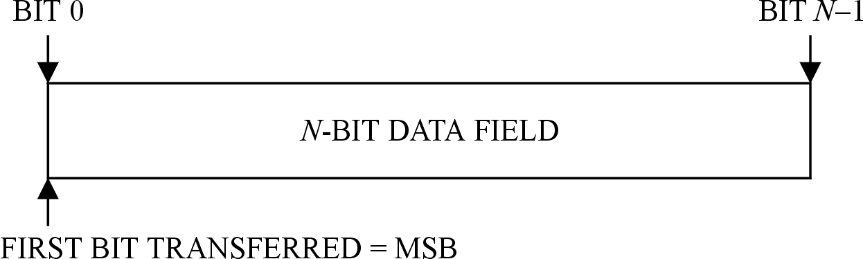 Figure 31: numbering convention
Most significant bit
When an N-bit field is used to express a binary value (such as a counter), the most significant bit is the first bit of the field, i.e. bit 0 (see Figure 31).
Use of capitals for the names of data structures and fields
In this Standard initial capitals are used for the names of data structures and fields.
This enables field names to be easily identified in the surrounding text.
For example, the field Frame Length is easier to see than frame length in text containing words such as frame and length. It also prevents ambiguity over where the name begins and ends.
Overview
Presentation
This Standard describes the data structures and protocols used in space missions to transmit data on telecommand space data links. It is designed to meet the requirements of space missions for the reliable transfer of telecommands over ground-to-space or space-to-space communications links.
Annex E describes the mission configuration parameters within the scope of this Standard.
The functions and protocols of the telecommand space link are grouped into layers and sublayers. The functions and protocols addressed in this Standard are grouped as follow:
the segmentation sublayer,
the transfer sublayer,
the synchronization and channel coding sublayer, and
the procedures in the physical layer at the sending end.
The segmentation sublayer, the transfer sublayer and the synchronization and channel coding sublayer are sublayers of the data link layer.
The layers and sublayers defined in this Standard provide a means for transferring data units on behalf of higher layers.
In general, the procedures, protocols and functions defined in this Standard are not concerned with the format, contents or applications of the higher layer data units. The only exception is the blocking function of the segmentation sublayer: the higher layer data units which use this function are restricted to certain packet types.
Protocol profiles
Figure 41 illustrates the following:
The relationship of the layers and sublayers specified in this Standard.
The data structures passed between the peer entities. The data structures are introduced in the overview clauses 4.3 to 4.5.
The protocol profile for a project can differ from the profile represented by Figure 41.
When defining the layers and sublayers in this Standard, reference is sometimes made to one of the other layers or sublayers, but such references are not intended to exclude differences from the profile represented by Figure 41.
The protocol profile in Figure 41 does not show any security sublayers. As part of the tailoring process described in Clause 1 a project with security requirements can insert security sublayers into the protocol profile of the telecommand space data link.
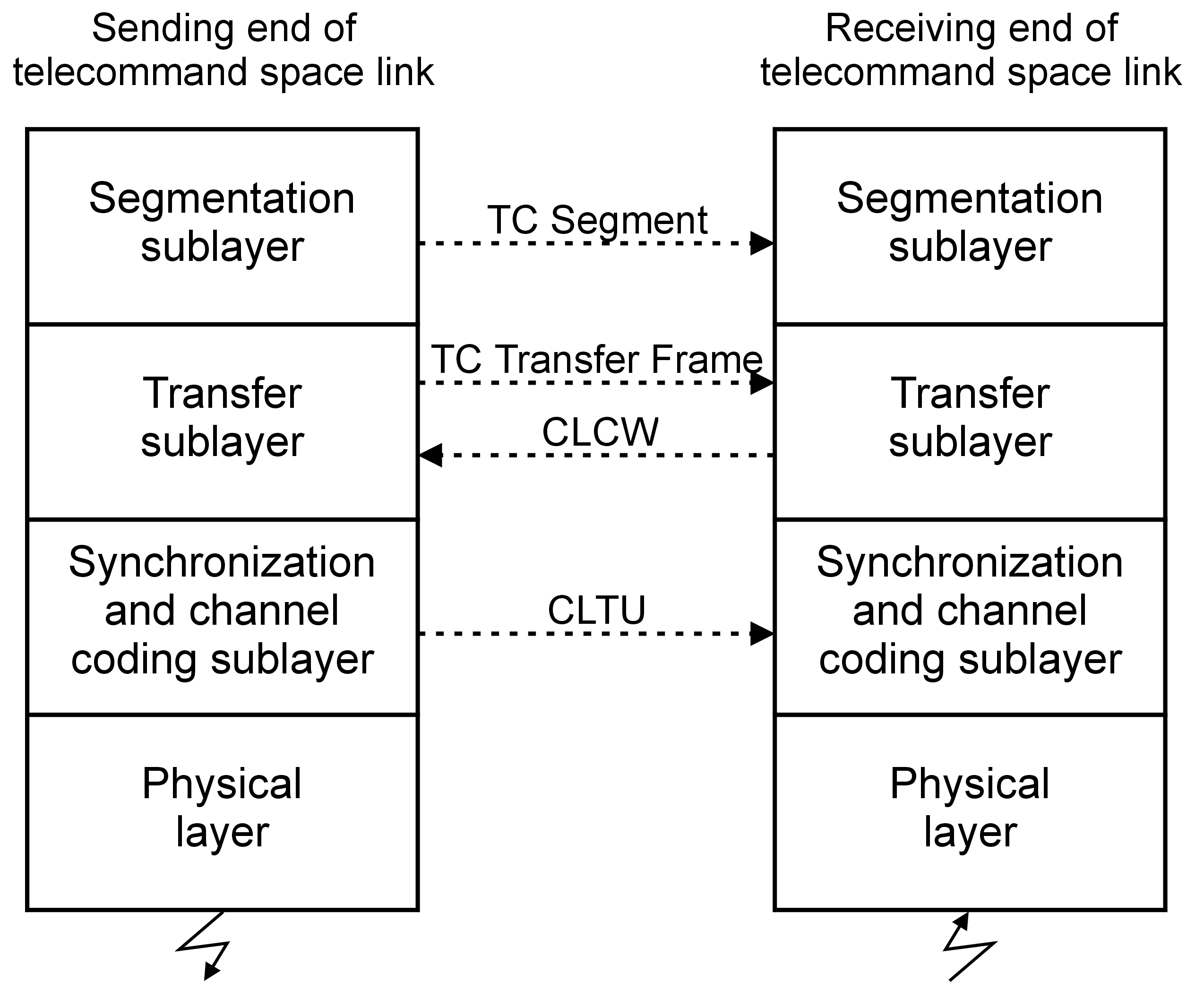 Figure 41: Layers and sublayers specified in this Standard
Segmentation sublayer
The TC segment contains fields to support two of the functions of the segmentation sublayer:
the segmentation function, and
a multiplexing function.
The segmentation function breaks long data units into smaller portions so that they are consistent with the limited length of the frames in the transfer sublayer. At the receiving end, the segmentation function reassembles the portions into the original data units.
The segmentation sublayer also includes a blocking function for packets so that multiple packets can be carried in a frame.
Clause 5 provides the specification of the segmentation sublayer and of the TC segment.
Transfer sublayer
The TC Transfer Frame is a variable-length data structure, designed for the efficient transfer of variable-length data units.
The transfer sublayer contains procedures for generating and processing TC Transfer Frames. The procedures include a multiplexing function.
The procedures are defined in Clause 6, which also includes the definition of the TC Transfer Frame.
The transfer sublayer includes the communications operation procedure (COP1), which operates the transmission protocol of the transfer sublayer. The detailed specification of COP-1 is given in Clause 7.
COP-1 supports two service types:
the sequence-controlled service, and
the expedited service.
COP-1 uses protocol status information which is passed from the transfer sublayer at the receiving end to the transfer sublayer at the sending end. The information is contained in a communications link control word (CLCW), which can be transmitted in a telemetry transfer frame.
Synchronization and channel coding sublayer
The synchronization and channel coding sublayer establishes an error-controlled data channel through which data can be transferred. The data is encoded, using a block code with error-correcting capabilities, to reduce the effects of noise on the data in the space channel.
The synchronization and channel coding sublayer includes procedures for information bit randomizing, to ensure frequent bit transitions in the communications channel. Synchronization for the codeblock and delimiting of the beginning of user data are provided by the communications link transmission unit (CLTU) data structure.
Clause 8 defines the synchronization and channel coding sublayer and also contains the definition of the CLTU.
In Annex D the performance of the coding and data structures in the synchronization and channel coding sublayer is discussed and the related frame error rates in the transfer sublayer.
Physical layer
The physical layer is the lowest layer of the telecommand space link. In this Standard the physical layer is designed to work together with the synchronization and channel coding sublayer. It accepts CLTUs from the synchronization and channel coding sublayer at the sending end. At the receiving end it supplies the synchronization and channel coding sublayer with a symbol stream containing the CLTUs.
Clause 9 defines the physical layer procedures, including the associated data structures.
Other aspects of the physical layer, such as radio frequency characteristics, are outside the scope of this Standard.
Virtual channels
The TC Transfer Frame supports the division of the physical channel into multiple logically-separate virtual channels by means of identifier fields in the header of a TC Transfer Frame. The identifier fields are the Virtual Channel Identifier and the Spacecraft Identifier. The virtual channel multiplexing is a procedure of the transfer sublayer.
This Standard does not specify the manner in which the virtual channels are multiplexed into a physical channel: the Spacecraft Identifier can be included as part of the multiplexing process in a given implementation. Clause 6.9 defines virtual channel multiplexing.
Segmentation sublayer
Overview
The segmentation sublayer accepts variable-length octet-aligned data units from the next higher layer or sublayer at the sending end and delivers them to the next higher layer or sublayer at the receiving end. Within the segmentation sublayer these data units are referred to as user data units.
The segmentation sublayer provides three functions: blocking, segmentation and multiplexing.
The blocking function combines multiple user data units so that they are carried in a single frame of the transfer sublayer. The user data units for the blocking function are limited to packets.
The segmentation function breaks long user data units into multiple shorter portions at the sending end and reassembles them at the receiving end.
User data units allocated to different multiplexer access points (MAPs) are multiplexed together so that they share one virtual channel of the transfer sublayer.
The principal data structure in the segmentation sublayer is the TC Segment. This is a variable-length data structure containing an integral number of octets. The TC Segment has fields in its header to support segmentation and MAP multiplexing.
If segmentation or MAP multiplexing is used for a virtual channel, then the virtual channel uses TC Segments.
If neither segmentation nor MAP multiplexing is used for a virtual channel, then the use of TC Segments on the virtual channel is optional. A physical channel can have some virtual channels that use TC Segments and some virtual channels that do not.
At the sending end, the data units generated by the segmentation sublayer are passed to the next lower sublayer:
It is assumed that the next lower sublayer accepts variable-length data units from the segmentation sublayer.
The next lower sublayer can set maximum length limitations for the data units it accepts from the segmentation sublayer.
When the segmentation function is in use, it is also assumed that the next lower sublayer can provide a service which ensures that the data units are delivered to the receiving end in sequence and without gaps or duplication.
TC Segment
General
The length of the TC Segment shall not exceed the maximum length accepted by the next lower sublayer below the segmentation sublayer.
- 1 The TC Segment is a variable-length data structure.
- 2 The maximum length accepted by the transfer sublayer can vary across different virtual channels.
The length of a TC Segment shall be an integer number of octets.
A TC Segment shall consist of two fields, positioned contiguously, in the following sequence: - Segment Header 8 bits
- Segment Data Field variable length
The format of the TC Segment is shown in Figure 51.
If the next lower sublayer below the segmentation sublayer is the transfer sublayer, and the segmentation sublayer at the sending end is generating TC Segments for a particular virtual channel, then all data units delivered by the transfer sublayer at the receiving end for that virtual channel shall be TC Segments.
TC Segments do not share a virtual channel with other data structures.
If the next lower sublayer below the segmentation sublayer is the transfer sublayer, then each TC Segment shall be placed in the Transfer Frame Data Field of a TC Transfer Frame such that the Transfer Frame Data Field contains exactly one complete TC Segment.
In this case, the length of the Transfer Frame Data Field is equal to the length of the TC Segment.
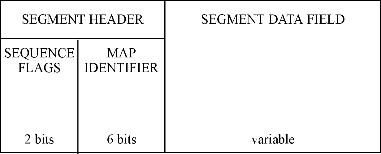 Figure 51: TC Segment
Segment Header
General
The Segment Header shall always be present in a TC Segment.
The Segment Header shall be contained in bits 0-7 of the TC Segment.
The Segment Header shall consist of two fields, positioned contiguously, in the following sequence:
- Sequence Flags 2 bits
- MAP Identifier 6 bits
Both fields are always present in a Segment Header.
Sequence Flags
The Sequence Flags shall always be present in a Segment Header.
The Sequence Flags shall be contained in bits 0-1 of the Segment Header.
The Sequence Flags shall be set as follows:
- ‘01’ for the first segment of a user data unit;
- ‘00’ for a continuing segment of a user data unit;
- ‘10’ for the last segment of a user data unit;
- ‘11’ no segmentation.
The Sequence Flags provide information about the sequential position of the segment to enable the receiving end to reassemble the user data units from a stream of segments. However, the flags do not provide a sequence count, so the reassembly process depends on the stream of segments being delivered in sequence and without omissions. The sequence-controlled service of the transfer sublayer can provide delivery in sequence and without omissions.
MAP Identifier
The MAP Identifier shall always be present in a Segment Header.
The MAP Identifier shall be contained in bits 2-7 of the Segment Header.
The six-bit MAP Identifier enables up to 64 MAPs, from MAP 0 to MAP 63, to be associated with each virtual channel of the transfer sublayer.
The MAP Identifier shall provide the identification of the MAP to which the TC Segment belongs.
- 1 There are no restrictions on the selection of MAP Identifiers. The MAPs need not be numbered consecutively. However, if the packet assembly controller defined in clause 5.5.4 is in use, then MAPs are handled in pairs and the additional requirements specified in clause 5.5.4.2 apply.
- 2 When a user data unit is placed in a sequence of TC Segments, then all the TC Segments for the user data unit have the same value for the MAP Identifier.
If MAP multiplexing is not used on a particular virtual channel of the transfer sublayer, the MAP Identifier shall have a constant value for all TC Segments on that virtual channel.
In this case the virtual channel has a single MAP.
Segment Data Field
The Segment Data Field shall always be present in a TC Segment, except as specified in 5.2.3e.
The Segment Data Field shall start at bit 8 of the TC Segment.
The maximum length of the Segment Data Field is one octet less than the maximum length of a TC Segment.
The length of the Segment Data Field is variable.
The length of the Segment Data Field shall be an integer number of octets.
If the packet assembly controller defined in clause 5.5.4 is in use, then the Segment Data Field may be absent from some TC Segments.
When the packet assembly controller is in use, some MAPs can carry control segments. A control segment is a special case of a TC Segment that has no Segment Data Field.
Transfer notification
Overview
The sequence-controlled service of the COP-1 protocol of the transfer sublayer uses acknowledgements to obtain positive confirmation that data units have arrived at the transfer layer at the receiving end. The data units are the frame data units carried in type-A TC Transfer Frames.
In the transfer notification (AD service) signal, COP-1 uses the Positive Confirm and Negative Confirm responses to provide information about the delivery status of a data unit. The transfer notification signal is defined in clause 7.4.3.3, along with explanations of the meaning of the confirm responses.
The segmentation sublayer at the sending end takes the information obtained from the confirm responses and makes it available to the next higher layer or sublayer. If a user data unit is carried in multiple segments, the segmentation sublayer combines the confirm responses for the individual segments.
The mechanism by which the segmentation sublayer makes the information available to the next higher layer of sublayer is outside the scope of this Standard.
The handling by the segmentation sublayer at the sending end of other responses from the transfer notification (AD service) signal, or of information provided by other COP-1 signals, is outside the scope of this Standard.
Requirements
If a user data unit of the segmentation sublayer is transferred using the sequence-controlled service of the transfer sublayer, then the segmentation sublayer at the sending end shall provide, to the next higher layer or sublayer, the information about the delivery of the user data unit specified in clauses 5.3.2b to 5.3.2d.
If a user data unit is not divided into multiple segments, then the segmentation sublayer shall provide a Positive Confirm or Negative Confirm to the next higher layer or sublayer, according to the response contained in the COP-1 signal relating to the transfer of the user data unit.
If a user data unit is divided into multiple segments, then the segmentation sublayer shall provide a Positive Confirm to the next higher layer or sublayer if COP-1 has signalled Positive Confirm responses for all the segments.
If a user data unit is divided into multiple segments, then the segmentation sublayer shall provide a Negative Confirm to the next higher layer or sublayer if COP-1 has signalled a Negative Confirm response for one or more of the segments.
If some segments of a user data unit have been signalled by a Positive Confirm but at least one segment has been signalled by a Negative Confirm, then the segmentation sublayer provides a Negative Confirm for the user data unit.
Blocking of packets
Overview
Blocking of packets is performed by a blocking function at the sending end and a deblocking function at the receiving end.
The blocking function blocks multiple packets into a single data unit. The function is constrained by the limitations on the length of the data unit. Figure 52 illustrates an example.
Additional constraints can apply to the way the segmentation sublayer uses the blocking function.
For example, an implementation can set a limit for the delay imposed on a packet while waiting for more packets to be blocked with it. The additional constraints and the mechanisms for ensuring transmission of all packets are implementation dependent and outside the scope of this Standard.
The deblocking function uses fields in the standard packet headers in order to extract the packets. The function therefore depends on knowledge of the position, size and meaning of certain fields in the headers.
Blocking can be used with or without TC Segments.
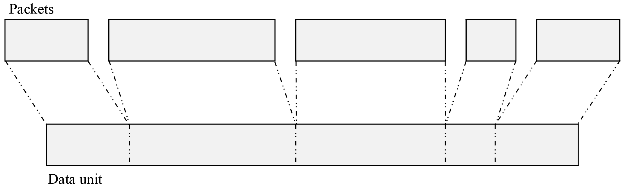 Figure 52: Example of blocking of packets
Virtual channels where TC Segments are used
The blocking and deblocking functions shall be conducted independently for each MAP.
The length of the data unit resulting from blocking shall not exceed the maximum length of the Segment Data Field of a TC Segment.
A virtual channel may have some MAPs where the blocking of packets is enabled and some MAPs where the blocking of packets is not enabled.
If the blocking of packets is enabled for a MAP, then all data units for that MAP, that are passed to the segmentation sublayer from the next higher layer or sublayer at the sending end, shall be packets with the properties defined in clause 5.4.4.
If the blocking function blocks multiple packets into a data unit, then the Sequence Flags of the TC Segment which carries the data unit shall be set to indicate no segmentation.
A data unit containing multiple packets is not divided into multiple segments by the segmentation function.
Virtual channels where TC Segments are not used
The blocking and deblocking functions shall be conducted independently for each virtual channel.
The length of the data unit resulting from blocking shall not exceed the maximum length of the data units accepted by the next lower sublayer below the segmentation sublayer.
A physical channel may have some virtual channels where the blocking of packets is enabled and some virtual channels where the blocking of packets is not enabled.
If the blocking of packets is enabled for a virtual channel, then all data units for that virtual channel, which are passed to the segmentation sublayer from the next higher layer or sublayer at the sending end, shall be packets with the properties defined in clause 5.4.4.
Packet properties
A packet handled by the blocking function shall have a defined Packet Version Number in conformance with CCSDS 135.0-B-3 clause 7.6 and with the definition of the related data structure specified in the same clause.
- 1 The Packet Version Number occupies the first three bits of the packet header.
- 2 CCSDS 135.0-B-3 clause 7.6 contains a list of the defined Packet Version Numbers, which are also referred to as authorized Packet Version Numbers. It provides also references to the documents that specify the related packet data structures.
- 3 For missions that use the blocking function, it is the responsibility of the mission designer to verify the availability of support by the telecommand transfer services for each defined Packet Version Number to be used by the mission.
Blocking function
Multiple complete packets may be placed contiguously into a data unit.
- 1 The blocking function is only applied to complete packets.
- 2 Due to other constraints, such as implementation-dependent time limits, the segmentation sublayer can choose not to block some packets.
The order of the packets shall not be changed to improve the blocking of the packets into the data units.
The order of arrival of the packets is preserved.
Packets with different Packet Version Numbers may be blocked into the same data unit.
If the blocking function processes packets for the sequence-controlled service and packets for the expedited service, then all packets that are blocked into the same data unit shall be for the same service.
The transfer sublayer supports the sequence-controlled service and the expedited service.
Deblocking function
The deblocking function shall extract the packets from the data units it receives.
To perform the extraction, the deblocking function shall use the packet length fields, together with the length of the received data unit.
The deblocking function inspects the Packet Version Number of each packet in order to locate and interpret the packet length field.
Segmentation
Overview
A segmenting function at the sending end breaks long user data units into multiple portions which are placed in a sequence of TC Segments. At the receiving end, a reassembly function reassembles the user data units. The functions are conducted independently for each MAP.
All TC Segments belonging to a specific user data unit have the same value for the MAP Identifier and use the same service (sequence-controlled service or expedited service) in the transfer sublayer.
Successful operation of the segmentation function relies on the stream of TC Segments being delivered in sequence and without omissions. The sequence-controlled service can provide delivery in sequence and without omissions.
Figure 53 illustrates an example of segmentation of a user data unit.
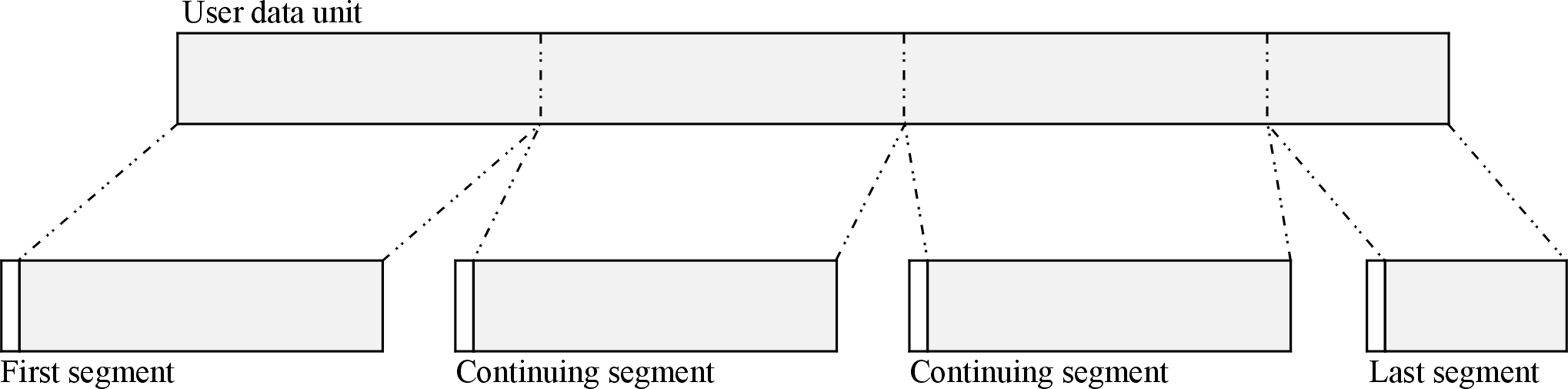 Figure 53: Example of segmentation of a user data unit
Segmenting function
The segmenting function shall be conducted independently for each MAP.
If a user data unit exceeds the maximum length of a Segment Data Field, the segmenting function shall split it as follows:
- For each portion, select the length of the portion such that it is an integer number of octets that does not exceed the maximum length of a Segment Data Field.
- Place the portions in order into a sequence of TC Segments.
- Place the first octet of the user data unit in the first octet of the Segment Data Field of the first TC Segment.
- Set the Sequence Flags of each TC Segment in the sequence to indicate whether it is a first, continuing or last segment.
- 1 The Segment Data Field in the first and continuing TC Segments can have a length equal to the maximum length of the Segment Data Field. The Segment Data Field in the last TC Segment has a length equal to the residue of the user data unit.
- 2 If a user data unit does not exceed the maximum length of a Segment Data Field, the complete user data unit is placed in a single TC Segment. In this case the Sequence Flags are set to indicate no segmentation.
Reassembly function
The reassembly function shall be conducted independently for each MAP.
The reassembly function shall reassemble the Segment Data Fields from a sequence of TC Segments to recreate the original user data unit.
To perform the reassembly, the reassembly function shall use the Sequence Flags together with the lengths of the TC Segments.
- 1 If a failure occurs during reassembly, the actions are undefined. The choice of whether to deliver the incomplete or faulty user data unit to the next higher layer or sublayer is implementation dependent.
- 2 The optional packet assembly controller defined in clause 5.5.4 specifies additional actions for the reassembly function, including the behaviour in the event of a reassembly failure.
Packet assembly controller
Overview
The packet assembly controller (PAC) can form part of the reassembly function at the receiving end of the segmentation function.
The reassembly function reassembles the segments for each MAP connection, in order to recreate the original user data units. The packet assembly controller carries out the reassembly, including the handling of exceptions.
When the PAC detects an exception it enters a lockout state. In the lockout state, the PAC does not reassemble user data units nor pass user data units to the next higher layer or sublayer. When it receives a MAP reset command, the PAC exits lockout state.
Despite the word “packet” in its name, the actions of the PAC apply to all user data units carried in TC Segments. The actions are not limited to any specific data structures. The name “packet assembly controller” is inherited from earlier standards.
If the segmentation function is not in operation, then the PAC is not used.
PAC for a pair of MAPs
There shall be one PAC for each pair of MAP connections.
A pair of MAP connections shall consist of one MAP for data and one MAP for control.
The MAP Identifier for the data MAP shall have the most significant bit set to ‘0’.
The MAP Identifier for the control MAP shall have the same value as the data MAP except that the most significant bit shall be set to ‘1’.
A TC Segment carrying user data shall have the MAP Identifier of the data MAP.
A TC Segment which is a PAC control segment shall have the MAP Identifier of the control MAP.
- 1 The MAP Identifier is a 6-bit value, carried in the Segment Header. Therefore, for a pair of MAPs:
- the data MAP has an identifier in the range 0 to 31;
- the control MAP has an identifier in the range 32 to 63;
- control MAP Identifier = data MAP Identifier + 32;
- the least significant 5 bits of the two MAP Identifiers are the same.
- 2 The PAC requirements on the use of the MAP Identifier apply in addition to the MAP Identifier specification in clause 5.2.2.3.
Reassembly of user data units
The PAC reassembly function shall use the Sequence Flags in the Segment Header of each TC Segment to reassemble the user data units.
- 1 The reassembly function implies that the number of octets in each segment is known by the
- 2 The PAC reassembly function does not use any knowledge of the structure of the user data units.
For example, it does not make use of any length fields contained in the user data units. If the user data units have length fields, then verification that the length of the reassembled data unit is consistent with the value in the length field is outside the scope of this Standard.
PAC state
The PAC shall enter a lockout state when it detects one of the following errors:
- an incorrect sequence of data segments, as indicated by the Sequence Flags;
- a control segment with an invalid format.
When the PAC is in a lockout state, it shall not reassemble user data units nor pass user data units to the next higher layer or sublayer.
When the PAC is in a lockout state, it shall remain in that state until it receives a valid control segment as specified in clause 5.5.4.6. - 1 The following is a list of the incorrect sequences of segments that causes the PAC to enter lockout state. The values for the Sequence Flags are shown in parentheses.
- A first segment (‘01’) followed by a first segment (‘01’).
- A first segment (‘01’) followed by a no segmentation (‘11’).
- A continuing segment (‘00’) followed by a first segment (‘01’).
- A continuing segment (‘00’) followed by a no segmentation (‘11’).
- A last segment (‘10’) followed by a continuing segment (‘00’).
- A last segment (‘10’) followed by a last segment (‘10’).
- A no segmentation (‘11’) followed by a continuing segment (‘00’).
- A no segmentation (‘11’) followed by a last segment (‘10’)
- 2 The lockout state of the PAC is unrelated to the FARM1 Lockout state defined in clause 7.2.3.2.
PAC status report
The PAC shall have a reassembly status flag set as follows:
- ‘0’ when the PAC has completed reassembly of a user data unit;
- ‘1’ when reassembly of a user data unit is in progress in the The PAC shall have a lockout status flag set as follows:
- ‘1’ when the PAC is in a lockout state;
- ‘0’ when the PAC is not in a lockout state. The PAC shall report its status to the sending end, including the following:
- the MAP Identifier of the data MAP, and
- the reassembly status flag, and
- the lockout status flag.
The correct operation of the PAC relies on the status of the PAC being known by the sending end. This Standard does not specify the format of the status information nor the mechanism to be used to transport it from the PAC to the appropriate entity at the sending end. It also does not specify any resulting behaviour at the sending end, such as the decision to send a control segment.
Control segment
A control segment shall have a length of one octet.
A control segment is a special case of a TC Segment. It has no Segment Data Field and therefore consists of a Segment Header only.
The Sequence Flags in the Segment Header of a control segment shall be set to ‘11’.
The MAP Identifier in the Segment Header of a control segment shall contain the MAP Identifier of a control MAP.
A valid control segment shall be considered to be a MAP reset command.
- 1 If the PAC receives a segment that has the MAP Identifier of a control MAP but the segment does not conform to the format rules the PAC enters lockout state.
- 2 This Standard does not specify any type of service (sequence-controlled service or expedited service) to be used for the transfer of a control segment.
MAP reset actions
When the PAC receives a MAP reset command and the PAC reassembly status flag is ‘1’, the PAC shall:
- discard the partially reassembled data unit, and
- set the reassembly status flag to ‘0’. When the PAC receives a MAP reset command and the PAC is in lockout state, the PAC shall exit lockout state.
The MAP reset command is used, for example, to recover from breaks in the sequence of TC Segments due to link difficulties or unplanned termination of transfer services.
MAP multiplexing
User data units allocated to different MAPs are multiplexed together so that they can share a virtual channel of the transfer sublayer. Each virtual channel can have up to 64 distinct MAPs (from MAP 0 to MAP 63) associated with it.
The MAP multiplexer selects a TC Segment depending on the priorities of the MAPs and the algorithm in use. This Standard does not specify any multiplexing algorithms. The type of priority scheme employed and the allocation of priorities to the individual MAPs is implementation dependent.
Although the multiplexing algorithms are implementation dependent, cross-support missions can specify the use of algorithms described in CCSDS 912.3-B-1.
If MAP multiplexing is in use, the order of arrival of user data units is not preserved across MAPs.
For example, a user data unit on a high-priority MAP can be processed before an earlier data unit on a low-priority MAP. Also, segments from user data units on different MAPs can be interleaved.
Transfer sublayer
Overview
Data structures in the transfer sublayer
The principal data structure in the transfer sublayer is the TC Transfer Frame, specified in clause 6.2. At the sending end, the transfer sublayer delivers TC Transfer Frames to the next lower sublayer.
The transfer sublayer accepts variable-length data units from the next higher sublayer at the sending end and delivers them to the next higher sublayer at the receiving end. Within the transfer sublayer, these data units are referred to as frame data units (FDUs) because each one is carried in the data field of a TC Transfer Frame. The transfer sublayer imposes constraints on the lengths of the data units.
The transfer sublayer at the receiving end accepts variable-length blocks containing an integral number of octets from the next lower sublayer. The transfer sublayer processes each received block as a candidate frame, to verify that it contains a valid TC Transfer Frame.
The operation of the transfer sublayer protocol uses status information which is passed from the receiving end to the sending end of the sublayer. The information is contained in a communications link control word (CLCW), which can be transmitted in a telemetry transfer frame. The format of the CLCW is defined in clause 6.3, and the processing for CLCWs in Clause 7.
Procedures in the transfer sublayer
Communications operation procedure
The transfer sublayer includes the communications operation procedure (COP), which operates the transmission protocol of the sublayer. A COP consists of a pair of synchronized procedures which execute within one virtual channel at the sending and receiving ends of the sublayer. This Standard defines one COP, called COP-1, whose detailed specification is contained in Clause 7. COP-1 supports two service types for data transfer: the sequence-controlled service and the expedited service.
Sending end
Table 61 shows the procedures in the transfer sublayer at the sending end.
At the sending end, the first procedure in the transfer sublayer is the frame operation procedure (FOP1), which is the sending end of COP-1.
The COP-1 procedures operate within a virtual channel so the transfer sublayer has an instance of FOP-1 for each virtual channel.
There are two procedures to complete the fields in each Transfer Frame:
the frame header procedure places values in the fields of the Transfer Frame Primary Header, and
the frame error control procedure then generates the frame check sequence and places it in the Frame Error Control Field.
The transfer sublayer includes virtual channel multiplexing. Because FOP-1 has an instance for each virtual channel, the virtual channel multiplexing is after FOP-1, but its position relative to the other two procedures is implementation dependent.
Table 61: Sending-end procedures in the transfer sublayer
|
Procedure
|
Clause
|
Position in the sequence of execution
|
(Peer procedureat the receiving end)
|
|
FOP-1
|
7
|
First procedure in the transfer sublayer
|
(FARM-1)
|
|
Frame headerprocedure
|
6.4
|
- After FOP-1
|
(Frame header validation procedure)
|
|
Frame error control procedure
|
6.5
|
After frame header procedure
|
(Frame error control procedure)
|
|
Virtual channel multiplexing
|
6.9
|
After FOP-1
|
(Virtual channel demultiplexing)
|
Receiving end
Table 62 shows the procedures in the transfer sublayer at the receiving end.
At the receiving end, the first procedure is the frame delimiting and fill removal procedure. This validates the length and removes any fill data from the end of each candidate frame.
The frame error control procedure verifies the frame check sequence in the Frame Error Control Field. The frame header validation procedure checks the remaining fields of the Transfer Frame Primary Header.
The last procedure is the frame acceptance and reporting mechanism (FARM-1), which is the receiving end of COP-1. The COP-1 procedures operate within a virtual channel so the transfer sublayer has an instance of FARM-1 for each virtual channel.
The transfer sublayer includes virtual channel demultiplexing, which is after the frame delimiting and fill removal procedure. Because FARM-1 has an instance for each virtual channel, the virtual channel demultiplexing is before FARM-1, but its position relative to the other two procedures is implementation dependent.
Table 62: Receiving-end procedures in the transfer sublayer
|
Procedure
|
Clause
|
Position in the sequence of execution
|
(Peer procedureat the sending end)
|
|
Frame delimiting and fill removal procedure
|
6.6
|
First procedure in the transfer sublayer
|
(none)
|
|
Frame error control procedure
|
6.7
|
- After frame delimiting and fill removal procedure
|
(Frame error control procedure)
|
|
Frame headervalidationprocedure
|
6.8
|
- After frame error control procedure- Before FARM-1
|
(Frame header procedure)
|
|
Virtual channel demultiplexing
|
6.9
|
- After frame delimiting and fill removal procedure- Before FARM-1
|
(Virtual channel multiplexing)
|
|
FARM-1
|
7
|
Last procedure in the transfer sublayer
|
(FOP-1)
|
TC Transfer Frame definition
General
The TC Transfer Frame shall consist of the major fields, positioned contiguously, in the following sequence:
- Transfer Frame Primary Header 5 octets
- Transfer Frame Data Field variable length
- Frame Error Control Field 2 octets
- 1 All three fields are always present in a TC Transfer Frame.
- 2 Figure 61 illustrates the detailed format of the TC Transfer Frame.
The length of a TC Transfer Frame shall be an integer number of octets. - 1 The TC Transfer Frame is a variable-length data structure.
- 2 The length of a TC Transfer Frame is indicated by the Frame Length field defined in clause 6.2.2.8. Because of constraints imposed by the Frame Length field, the length of a TC Transfer Frame does not exceed 1024 octets. For a mission, a value of less than 1024 octets can be selected for the length of the longest TC Transfer Frame that can be carried on a particular virtual channel.
- 3 The length of the Transfer Frame Data Field defined in clause 6.2.3 is not less than 1 octet. As a result, a TC Transfer Frame has a length which is not less than 8 octets.
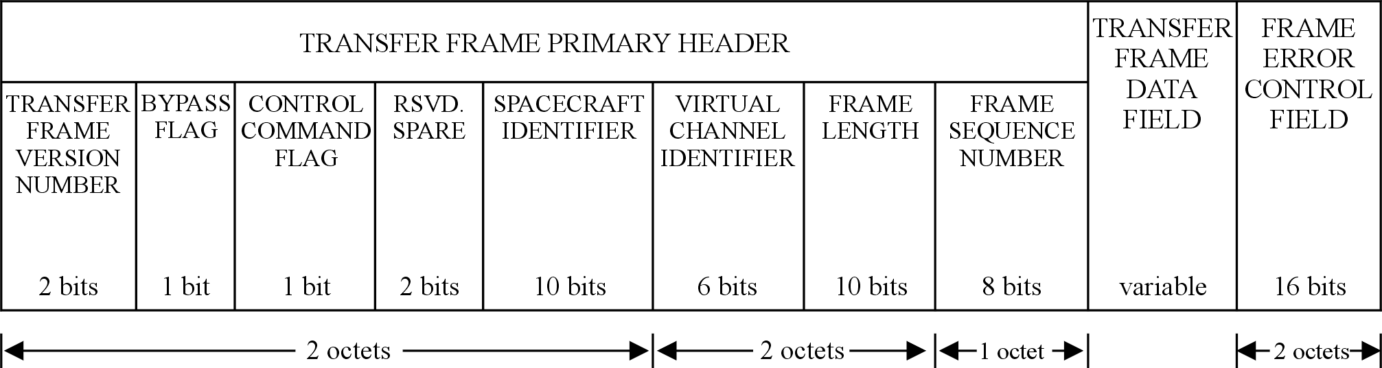 Figure 61: TC Transfer Frame format
Transfer Frame Primary Header
General
The Transfer Frame Primary Header shall always be present in a TC Transfer Frame.
The Transfer Frame Primary Header shall consist of eight fields, positioned contiguously, in the following sequence:
- Transfer Frame Version Number 2 bits
- Bypass Flag 1 bit
- Control Command Flag 1 bit
- Reserved Spare 2 bits
- Spacecraft Identifier 10 bits
- Virtual Channel Identifier 6 bits
- Frame Length 10 bits
- Frame Sequence Number 8 bits
All eight fields are always present in a Transfer Frame Primary Header.
Transfer Frame Version Number
The Transfer Frame Version Number shall always be present in a Transfer Frame Primary Header.
The Transfer Frame Version Number shall be contained in bits 0-1 of the Transfer Frame Primary Header.
The Transfer Frame Version Number shall be set to the binary value ‘00’.
The value '00' defines version 1 of the TC Transfer Frame. Other values of this field are reserved.
Bypass Flag
The Bypass Flag shall always be present in a Transfer Frame Primary Header.
The Bypass Flag shall be contained in bit 2 of the Transfer Frame Primary Header.
The Bypass Flag shall be set as follows:
- ‘0’ for a type-A Transfer Frame;
- ‘1’ for a type-B Transfer Frame. The Bypass Flag shall be interpreted in combination with the Control Command Flag as defined in Table 63.
- 1 When the Bypass Flag is set to ‘1’, the TC Transfer Frame bypasses the sequence control checks at the receiving end of the COP-1 procedures.
- 2 To operate the sequence-controlled service, a virtual channel carries type-A and type-B Transfer Frames.
Control Command Flag
The Control Command Flag shall always be present in a Transfer Frame Primary Header.
The Control Command Flag shall be contained in bit 3 of the Transfer Frame Primary Header.
The Control Command Flag shall be set as follows:
- ‘0’ for a type-D Transfer Frame, carrying data;
- ‘1’ for a type-C Transfer Frame, carrying a control command. The Control Command Flag shall be interpreted in combination with the Bypass Flag as defined in Table 63.
A control command is a protocol control instruction used in COP-1 to configure the procedures at the receiving end.
Table 63: Combined Bypass Flag and Control Command Flag
|
Bypass Flag
|
Control Command Flag
|
Interpretation
|
|
0
|
0
|
AD frame, carrying data in the sequence-controlled service
|
|
0
|
1
|
Reserved for future application
|
|
1
|
0
|
BD frame, carrying data in the expedited service
|
|
1
|
1
|
BC frame, carrying a control command
|
Reserved Spare
The spare field contained in bits 4-5 of the Transfer Frame Primary Header shall be set to ‘00’.
The use of this spare field is reserved for future applications.
Spacecraft Identifier
The Spacecraft Identifier shall always be present in a Transfer Frame Primary Header.
The Spacecraft Identifier shall be contained in bits 6-15 of the Transfer Frame Primary Header.
The Spacecraft Identifier shall provide the identification of the destination spacecraft for the TC Transfer Frame.
The Spacecraft Identifier shall be static throughout all mission phases.
- 1 The Secretariat of the CCSDS assigns Spacecraft Identifiers according to the procedures in CCSDS 320.0-B-4.
- 2 Different Spacecraft Identifiers can be assigned for normal operations and for development vehicles using the ground networks during pre-launch test operations, and for simulated data streams.
- 3 A single physical channel can carry virtual channels with different Spacecraft Identifiers. Therefore the Spacecraft Identifier forms part of the full identification of a virtual channel within the physical channel.
Virtual Channel Identifier
The Virtual Channel Identifier shall always be present in a Transfer Frame Primary Header.
The Virtual Channel Identifier shall be contained within bits 16-21 of the Transfer Frame Primary Header.
The Virtual Channel Identifier, together with the Spacecraft Identifier, shall identify the virtual channel to which the Transfer Frame belongs.
- 1 The Virtual Channel Identifier is also used in the CLCW defined in clause 6.3. As described in clause 6.3.6, the choice of values for the identifiers of the virtual channels can affect the risk of misidentifying the virtual channel for a CLCW.
- 2 The Spacecraft Identifier forms part of the identification of a virtual channel within a physical channel.
Frame Length
The Frame Length shall always be present in a Transfer Frame Primary Header.
The Frame Length shall be contained in bits 22-31 of the Transfer Frame Primary Header.
The Frame Length shall contain a binary number equal to the number of octets in the TC Transfer Frame minus 1.
The value contained in the Frame Length is in the range 7 to 1023, corresponding to TC Transfer Frame lengths of 8 to 1024 octets.
The value contained in the Frame Length may be variable.
Earlier definitions limited the TC Transfer Frame length to a maximum of 256 octets. In the earlier definitions, the Frame Length is contained in bits 24-31 of the Transfer Frame Primary Header, and is preceded by a 2-bit reserved field containing zeroes. Therefore, frames that conform to the earlier definition are valid under the current definition.
Frame Sequence Number
The Frame Sequence Number shall always be present in a Transfer Frame Primary Header.
The Frame Sequence Number shall be contained in bits 32-39 of the Transfer Frame Primary Header.
In type-A Transfer Frames the Frame Sequence Number shall contain the COP-1 value N(S).
- 1 Clause 7.9.2.6 specifies the setting of the COP-1 value N(S).
- 2 The value is used in the COP-1 procedures at the receiving end to check that incoming type-A Transfer Frames are in sequence.
In type-B Transfer Frames the Frame Sequence Number shall be set to zero.
The Bypass Flag defined in clause 6.2.2.3 indicates if a TC Transfer Frame is type-A or type-B.
Transfer Frame Data Field
The Transfer Frame Data Field shall always be present in a TC Transfer Frame.
The Transfer Frame Data Field shall follow, without gap, the Transfer Frame Primary Header.
The length of the Transfer Frame Data Field shall be an integral number of octets.
- 1 The length of the Transfer Frame Data Field is constrained by the length of the total TC Transfer Frame. The constraints on the length of a TC Transfer Frame are described in clause 6.2.1.
- 2 The length of the Transfer Frame Data Field is not less than 1 octet and does not exceed 1017 octets.
In type-D Transfer Frames the Transfer Frame Data Field shall contain a frame data unit.
The Transfer Frame Data Field of a type-D Transfer Frame contains exactly one frame data unit. The length of a frame data unit is therefore constrained to be a valid length for the field.
In type-C Transfer Frames the Transfer Frame Data Field shall contain a COP-1 control command.
The Control Command Flag defined in clause 6.2.2.3 indicates if a TC Transfer Frame is type-D or type-C. Clause 6.1.1 describes the frame data unit. The COP-1 control commands are specified in clause 7.8.
Frame Error Control Field
General
The Frame Error Control Field shall always be present in a TC Transfer Frame.
The Frame Error Control Field shall follow, without gap, the Transfer Frame Data Field.
The Frame Error Control Field shall have a length of two octets.
The error detection encoding and decoding procedures specified in clauses 6.2.4.2 and 6.2.4.3 shall be used.
- 1 This field provides a capability for detecting errors introduced into the frame during the transmission and data handling process. One reason for including this field in all TC Transfer Frames is to protect against residual errors after codeblocks are decoded in error-correcting mode as specified in clause 8.8.2.
- 2 When applied to an encoded block of less than 32 768 bits (4096 octets), the code has the following capabilities:
- All error sequences composed of an odd number of bit errors are detected.
- All error sequences containing two-bit errors anywhere in the encoded block are detected.
- If a random error sequence containing an even number of bit errors ( 4) occurs within the block, the probability that the error is undetected is approximately 2–15 (or 3 × 10⁻⁵).
- All single error bursts spanning 16 bits or less are detected provided no other errors occur within the block.
Encoding Procedure
The encoding procedure shall be as follows:
- The encoding procedure accepts an (n–16)-bit TC Transfer Frame, excluding the Frame Error Control Field, and generates a systematic binary (n,n16) block code by appending a 16-bit Frame Error Control Field as the final 16 bits of the codeblock.
- The equation for the contents of the Frame Error Control Field is: FECF = [(X16 M(X)) + (X(n16) L(X))] modulo G(X)
where
all arithmetic is modulo 2;
FECF is the 16-bit Frame Error Control Field and the first bit transferred is the most significant bit, taken as the coefficient of the highest power of X;
n is the number of bits in the encoded message;
M(X) is the (n16)-bit information message to be encoded expressed as a polynomial with binary coefficients, and the first bit transferred is the most significant bit M0 taken as the coefficient of the highest power of X;
L(X) is the presetting polynomial given by:
L(X) =
G(X) is the generating polynomial given by:
G(X) = X16 + X12 + X5 + 1
- 1 The X(n–16) L(X) term has the effect of presetting the shift register to all ‘1’ state prior to encoding.
- 2 The encoding has the characteristics of a cyclic redundancy code.
- 3 A sample implementation of an encoder is described in Annex A.
Decoding Procedure
The decoding procedure shall use an error detection syndrome, S(X), given by:
S(X) = [(X16 C*(X)) + (Xn L(X))] modulo G(X)
where
C*(X) is the received block, including the Frame Error Control Field, in polynomial form, with the first bit transferred being the most significant bit C0 taken as the coefficient of the highest power of X, and
S(X) is the syndrome polynomial, which is zero if no error is detected and non-zero if an error is detected, with the most significant bit S0 taken as the coefficient of the highest power of X.
A sample implementation of a decoder is described in Annex A.
The Frame Error Control Field shall not be used for error correction.
The code is intended for error detection purposes only.
CLCW definition
General
The length of a CLCW shall be 4 octets.
A CLCW shall consist of the fields shown in Table 64.
The table defines the position and length of each field. All the fields are always present in a CLCW. The format of a CLCW is shown in Figure 62.
Table 64: Fields in a CLCW
|
Field
|
Location (bits)
|
Length in bits
|
|
Control Word Type
|
0
|
1
|
|
CLCW Version Number
|
1-2
|
2
|
|
Status Field
|
3-5
|
3
|
|
COP in Effect
|
6-7
|
2
|
|
Virtual Channel Identification
|
8-13
|
6
|
|
Reserved Spare
|
14-15
|
2
|
|
No RF Available Flag
|
16
|
1
|
|
No Bit Lock Flag
|
17
|
1
|
|
Lockout Flag
|
18
|
1
|
|
Wait Flag
|
19
|
1
|
|
Retransmit Flag
|
20
|
1
|
|
FARM B Counter
|
21-22
|
2
|
|
Reserved Spare
|
23
|
1
|
|
Report Value
|
24-31
|
8
|
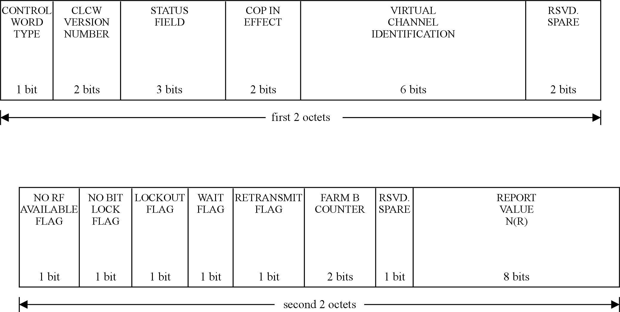 Figure 62: Format of a CLCW
A CLCW shall be conveyed in the Operational Control Field of a telemetry transfer frame.
The telemetry transfer frame can be a version 1 telemetry transfer frame as defined in ECSSEST-5003 or a version 2 telemetry transfer frame as defined in CCSDS 732.0-B-2.
A CLCW shall only be delivered to the FOP-1 if it has been extracted from an error-free telemetry transfer frame.
If any errors in the frame are successfully corrected, the frame is considered error-free.
A CLCW shall only be delivered to the FOP-1 of a virtual channel if it has been extracted from a telemetry transfer frame from the spacecraft to which that telecommand virtual channel belongs.
- 1 The purpose of a CLCW is to carry COP-1 protocol status information from the FARM-1 procedure at the receiving end to the FOP-1 procedure at the sending end.
- 2 The COP-1 procedures operate within a virtual channel. CLCWs are generated for each active virtual channel.
- 3 Although no reporting rate is specified, efficient operation of COP-1 can only be achieved if some minimum CLCW sampling rate is provided. The sampling rate is one of the factors used in selecting the FOP-1 timer value described in clause 7.2.2.9.
Control Word Type
The Control Word Type shall be set to the binary value ‘0’.
The Control Word Type is used to distinguish between a CLCW and other uses of the Operational Control Field. For a CLCW, this field is always zero.
CLCW Version Number
The CLCW Version Number shall be set to the binary value ‘00’.
The value zero indicates that the CLCW is a Version-1 CLCW. Other values of this field are reserved for future use.
Status Field
The use of the Status Field may be defined for mission-specific enhancements to telecommand operations.
If the use of the Status Field is not defined for a given mission, the Status Field shall be set to the binary value ‘000’.
COP in Effect
The COP in Effect shall be set to the binary value ‘01’.
The value 1 indicates that COP-1 is in effect. Other values of this field are reserved for future use.
Virtual Channel Identification
The Virtual Channel Identification shall identify the virtual channel to which the CLCW belongs.
- 1 The spacecraft identifier of the spacecraft that generated the CLCW also forms part of the identification of the virtual channel. The spacecraft identifier is not carried in the CLCW but is established by other means. The spacecraft identifier and the Virtual Channel Identification together identify the instance of the FOP-1 procedure which is the destination of the CLCW.
- 2 Telecommand virtual channel identifier values are assigned to maximize digital distance (i.e. hamming distance) between the values for the various virtual channels used by a spacecraft. This reduces the risk that an error introduced in a CLCW during on-board data handling changes the virtual channel identifier value into the value of another virtual channel used by the spacecraft.
- 3 A virtual channel identifier value consisting of all zeroes or all ones can be generated when a decoder fails or is powered off. Therefore virtual channel identifier values consisting of all zeroes or all ones are normally avoided.
- 4 The CLCW can be conveyed in a telemetry transfer frame, that contains a virtual channel identifier in its header. The field in the header identifies the telemetry virtual channel which carried the CLCW and is not related to the telecommand virtual channel described here.
Reserved Spare
The spare field contained within bits 14-15 of the CLCW shall be set to the binary value ‘00’.
The use of this spare field is reserved for future applications.
No RF Available Flag
The No RF Available Flag shall be set as follows:
- ‘0’ when the radio frequency physical connection is available through at least one of the spacecraft transponders;
- ‘1’ when the radio frequency physical connection is not available through any of the spacecraft transponders.
- 1 The value of this flag provides a logical indication of the ready status of the radio frequency elements within the physical data channel provided by the physical layer at the receiving end.
- 2 The presence of this flag in the CLCW fulfils an operational requirement. This does not preclude the transmission of telemetry data with more complete status information for monitoring purposes.
- 3 When the flag is ‘1’, TC Transfer Frames cannot be transferred without corrective action.
- 4 This flag is used by the physical layer procedures as defined in clause 9.3.
The No RF Available Flag shall always carry a true report of the status of the physical channel, even when other fields in the CLCW report the status of an inactive virtual channel.
The flag reports the status of the physical channel and therefore applies to all virtual channels.
No Bit Lock Flag
The No Bit Lock Flag shall be set as follows:
- ‘0’ when at least one of the spacecraft demodulation units for the physical channel has achieved bit lock;
- ‘1’ when none of the spacecraft demodulation units for the physical channel has achieved bit lock.
- 1 This flag provides an engineering measurement which indicates whether there is enough signal energy in the received data stream to achieve bit synchronization.
- 2 The presence of this flag in the CLCW fulfils an operational requirement. This does not preclude the transmission of telemetry data with more complete status information for monitoring purposes.
- 3 When the flag is ‘1’, this can indicate that the physical layer is not operating at the expected performance level and, as a result, that the TC Transfer Frame rejection rate can be abnormally high.
- 4 This flag is used by the physical layer procedures as defined in clause 9.3.
The No Bit Lock Flag shall always carry an actual report of the status of the physical channel, even when other fields in the CLCW report the status of an inactive virtual channel.
The flag reports the status of the physical channel and therefore applies to all virtual channels.
Lockout Flag
The Lockout Flag shall be set as follows:
- ‘1’ when the FARM-1 is in Lockout state;
- ‘0’ when the FARM-1 is not in Lockout state.
This flag is used by the COP-1 procedures as defined in clause 7.9.
Wait Flag
The Wait Flag shall be set as follows:
- ‘1’ when the FARM-1 is in Wait state;
- ‘0’ when the FARM-1 is not in Wait state.
This flag is used by the COP-1 procedures as defined in clause 7.9.
Retransmit Flag
The Retransmit Flag shall be set as follows:
- ‘0’ when the FARM-1 does not request retransmission;
- ‘1’ when the FARM-1 requests retransmission of type-A Transfer Frames, starting with the frame whose sequence number is indicated in the Report Value field of the CLCW.
This flag is used by the COP-1 procedures as defined in clause 7.9.
FARM-B Counter
The FARM-B Counter field of the CLCW shall contain the two least significant bits of the internal counter used by FARM-1 to count the accepted type-B Transfer Frames.
- 1 The FARM-1 maintains a counter which increments each time a type-B Transfer Frame is accepted.
- 2 This field can be used to verify that type-B Transfer Frames have been accepted. The verification process is not specified in this Standard. The field is not used by FOP-1.
- 3 The number of bits in the FARM-1 internal counter of accepted type-B Transfer Frames is implementation dependent. This field in the CLCW only carries the two least significant bits of the counter. This does not preclude the transmission in telemetry data of the full counter value.
Reserved Spare
The spare field contained in bit 23 of the CLCW shall be set to the binary value ‘0’.
The use of this spare field is reserved for future applications.
Report Value
The Report Value shall contain the COP-1 value N(R).
- 1 Clause 7.2.3.5 specifies the setting of this value.
- 2 This field informs the FOP-1 of the sequence number of the next frame expected at the FARM-1.
Frame header procedure
The frame header procedure is a procedure in the transfer sublayer at the sending end. The procedure places values in the fields of the Transfer Frame Primary Header of each TC Transfer Frame, so that when the frame leaves the procedure it is complete except for the Frame Error Control Field.
FOP-1 supplies the contents for the Transfer Frame Data Field. FOP-1 also supplies some of the values for the fields in the Transfer Frame Primary Header, as defined in clause 7.6.2.
The frame header procedure supplies the values for the remaining fields.
For example, it calculates the frame length from the length of the Transfer Frame Data Field.
Frame error control procedure at the sending end
The frame error control procedure at the sending end of the transfer sublayer generates the frame check sequence for the Frame Error Control Field.
Clause 6.2.4.2 defines the encoding procedure. The frame error control procedure executes the encoding procedure for each TC Transfer Frame and places the frame check sequence in the Frame Error Control Field.
A TC Transfer Frame is complete when it leaves the frame error control procedure.
Frame delimiting and fill removal procedure
Overview
The first procedure in the transfer sublayer at the receiving end is the frame delimiting and fill removal procedure, that validates the length of a candidate frame and removes any fill data.
Fill data can be present at the end of a candidate frame because of the behaviour of the next lower sublayer. In the synchronization and channel coding sublayer fill octets can be added to the end of a frame as defined in clause 8.6.2. The fill octets are not removed by the synchronization and channel coding sublayer at the receiving end, so fill removal is performed in the transfer sublayer.
Actions
If the length of the candidate frame is less than the minimum length of a TC Transfer Frame, then the candidate frame shall be discarded.
After comparison of the length of the candidate frame with the length indicated by the Frame Length field in the Transfer Frame Primary Header, the following actions shall be taken:
- If the length of the candidate frame is less than the length indicated by the Frame Length field, then discard the candidate frame.
- If the length of the candidate frame exceeds the length indicated by the Frame Length field, then remove the fill octets from the end of the candidate frame.
- 1 The minimum length of a TC Transfer Frame is 8 octets.
- 2 A candidate frame contains at most one TC Transfer Frame. The TC Transfer Frame is assumed to start at the beginning of the candidate frame.
- 3 For the purposes of finding the Frame Length field, the frame delimiting and fill removal procedure assumes that the candidate frame is a version 1 TC Transfer Frame, as defined in clause 6.2, although the Transfer Frame Version Number has not yet been validated.
- 4 Once a candidate frame has successfully passed the frame delimiting and fill removal procedure, it has the length indicated by the Frame Length.
Frame error control procedure at the receiving end
The frame error control procedure shall verify the frame check sequence in the Frame Error Control Field of each candidate frame it receives, using the decoding procedure defined in clause 6.2.4.3.
If the decoding procedure detects an error, the candidate frame shall be discarded.
Frame header validation procedure
Overview
The frame header validation procedure validates the fields in the Transfer Frame Primary Header of each candidate frame it receives.
The frame header validation checks are applied to a candidate frame, regardless of whether it is type-A or typeB.
Actions
For each candidate frame received from the frame error control procedure, the frame header validation procedure shall perform the following checks on the fields in the Transfer Frame Primary Header:
- The Transfer Frame Version Number has the expected value.
- The settings of the Bypass Flag and the Control Command Flag are a valid combination.
- The Spacecraft Identifier is the identifier of the receiving spacecraft.
- The Virtual Channel Identifier contains the identifier of a valid virtual channel.
- The Transfer Frame Primary Header does not contain any values that are inconsistent with the implemented features for the receiving spacecraft.
- 1 This Standard expects version 1 TC Transfer Frames, that have the Transfer Frame Version Number set to ‘00’.
- 2 Table 63 shows the valid combinations of the Bypass Flag and the Control Command Flag.
- 3 This requirement does not exclude implementations where some of the checks are performed by other procedures in the transfer sublayer.
- For example, the validity of the Virtual Channel Identifier can be checked as part of the virtual channel demultiplexing procedure.
If the candidate frame fails any of the checks, it shall be discarded.
If all the checks are successful, the candidate frame is considered to be a TC Transfer Frame.
Virtual channel multiplexing
Overview
The TC Transfer Frames support multiple virtual channels on a physical channel. The virtual channel multiplexing and demultiplexing take place within the transfer sublayer. See clauses 6.1.2.2 and 6.1.2.3 for a description of the position of the multiplexing and demultiplexing procedures relative to the other transfer sublayer procedures.
Multiplexing mechanism
The multiplexer selects a frame depending on the algorithm in use.
This Standard does not specify any multiplexing algorithms. Algorithms for cross-support missions can be found in CCSDS 912.3-B-1.
For a mission, the following depend on mission requirements:
the choice of multiplexing algorithm, and
where applicable, the allocation of priorities to the individual virtual channels.
Demultiplexing
As a result of the demultiplexing, the TC Transfer Frame is processed by the FARM-1 instance for the appropriate virtual channel.
This Standard describes the logical result of the virtual channel demultiplexing. It does not constrain the implementation mechanism.
For example, if virtual channels are used to support multiple telecommand units, then the demultiplexing can consist of discarding all frames that are not addressed to the unit in question.
COP-1
Overview
Scope
This clause contains the detailed specification of the logic of the Communications Operation Procedure-1 (COP-1) in the transfer sublayer.
COP-1 consists of a pair of synchronized procedures which execute within one virtual channel at the sending and receiving ends of the transfer sublayer. At the sending end, the Frame Operation Procedure-1 (FOP-1) is executed. At the receiving end, a corresponding Frame Acceptance and Reporting Mechanism-1 (FARM-1) is executed.
COP-1 is just one of the procedures performed within the transfer sublayer. It is the first procedure performed when a frame data unit (FDU) is received by the transfer sublayer at the sending end and the last one performed before the FDU is delivered to the next higher sublayer at the receiving end. Table 61 and Table 62 show the positions of the COP-1 procedures in the transfer sublayer.
Interfaces
In order to define the COP-1 services and protocols completely and clearly, some of the interactions on the COP-1 interfaces are also defined. The interactions are defined as signals which are passed across the interfaces. The purpose of the definitions is to ensure accountability of FDUs on the sequence-controlled service all the way from the next higher sublayer at the sending end to the destination spacecraft and back to the next higher sublayer.
Retransmission protocol
COP-1 is a closed-loop protocol that utilizes sequential “go-back-n” retransmission techniques. COP-1 ensures type-A Transfer Frames are only accepted by the spacecraft if they are received in strict sequential order (that is, there are no gaps or repetitions in the sequence) and their contents can be immediately passed on to the next higher sublayer.
Within COP-1, control of sequentiality is provided by FARM-1, and therefore frame sequence numbering is explicit. The Frame Sequence Number field in each type-A frame carries the sequence number. Type-A frames are transmitted by FOP-1 with their numbers arranged in strict increasing order. If one or more frames are missed, retransmission is initiated either in response to the Retransmit Flag in the communications link control word (CLCW) or to a timeout at the sending end. Window mechanisms prevent a new frame with the same sequence number as that of a missing frame from being transmitted or accepted.
Type-B frames, indicated by setting the Bypass Flag, are not subject to sequence checks. Valid type-B frames are always accepted.
Frames
This clause applies to the frames handled by COP-1. From the point of view of COP-1, a frame consists of an FDU plus the Transfer Frame Primary Header data generated by COP-1. The manner in which the frame is held in COP-1 is implementation dependent.
At the sending end, the values for the remaining fields of the TC Transfer Frame are generated by the frame header procedure and the frame error control procedure defined in clauses 6.4 and 6.5. The format of the TC Transfer Frame is specified in clause 6.2.
Services
Overview
COP-1 provides two distinct data transfer services to the next higher sublayer:
the sequence-controlled service, and
the expedited service.
The services are also referred to as service types.
Sequence-controlled service
The sequence-controlled service is also known as the AD service. This service concerns two types of frames:
AD frames carrying an FDU from the next higher sublayer;
BC frames carrying protocol control information for configuring COP-1.
The sequence-controlled service is based on an automatic repeat request (ARQ) procedure of the "go-back-n" type. It uses sequence-control mechanisms at the sending and receiving ends and relies on the presence of a standard report, the CLCW, returned in a telemetry frame.
At the sending end, the sequence-controlled service provides an interface for service management, by means of the directives defined in clause 7.4.2.2.
The service is initialised by one of the four initiate directives.
Two of these directives result in the transmission of a control command, contained in a type-BC frame. Each of the two control commands causes a well-defined action in FARM-1, which is then reflected in the CLCW. A timer is used to cause retransmission of the control command if the expected response is not received, with a limit on the number of automatic retransmissions before FOP-1 signals that there is a problem in initiating the AD service.
The other two directives start the AD Service without waiting for action by FARM-1, although one of them waits for receipt of a good CLCW.
Once the AD service has been initialised for the COP-1 on a particular virtual channel, FDUs are inserted into frames and transmitted on that virtual channel in the order in that they are presented to COP-1.
The retransmission mechanism ensures with a high probability of success the following:
no FDU is lost, and
no FDU is duplicated, and
no FDU is delivered out of sequence.
The AD service guarantees in-order delivery of FDUs on a single virtual channel. Because of retransmissions within a single virtual channel, there is no guarantee that FDUs on separate virtual channels, each using an AD service, are delivered to the next higher sublayer in the order initially transmitted.
For the transmission of type-AD frames, the automatic retransmission procedure makes use of several sequence variables, the most notable being:
Receiver_Frame_Sequence_Number, V(R);
Transmitter_Frame_Sequence_Number, V(S);
Next Expected Frame Sequence Number, N(R), contained in the Report Value of the CLCW;
Frame Sequence Number in the Transfer Frame Primary Header, N(S).
These variables are illustrated in Figure 71.
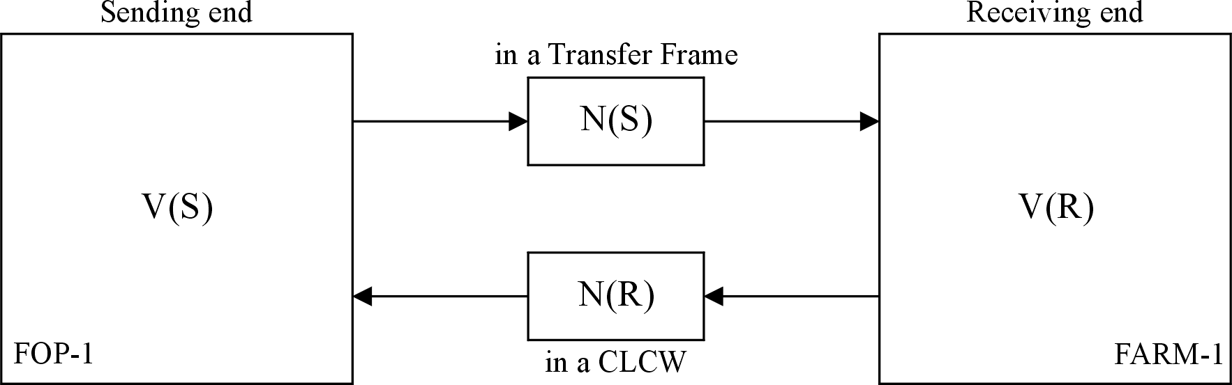 Figure 71: COP-1 sequence variables
The AD service also offers the wait system. This is a flow control mechanism that enables the receiving end to signal that it is not able to cope with the incoming rate of data.
For type-BC frames, the automatic retransmission procedure makes use of a very small number of variables; the most notable are
the Lockout Flag in the CLCW, used to confirm an Unlock control command, and
the value N(R) in the CLCW, used to confirm a Set V(R) control command.
Expedited service
The expedited service applies to type-BD frames and is also known as the BD service. Type-BD frames are used in exceptional operational circumstances, typically during spacecraft recovery operations. Although the BD service carries the name “expedited”, it does not provide a faster method for inserting a frame for immediate delivery into a stream of frames.
There is only one transmission for each type-BD frame (i.e. no retransmission). The expedited service delivers data in order and without duplication but with possible omissions.
At the sending end, type-BD frames are given immediate access, as specified by the FOP-1 state table. At the receiving end, the FDU carried by a type-BD frame is passed immediately to the next higher sublayer, even if the FARM-1 is in a Wait or Lockout state.
Also, in cases where the same buffer is used for FDUs carried by either type-AD or type-BD frames, then the data contained in incoming type-BD frames have priority.
Protocol machine
Each end of COP-1 is defined as a protocol machine that is described in a state table.
The basic operation principle of the protocol machine is that it remains in a state until an event occurs. When an event occurs, it is analyzed until it is fully identified and then the operations specified for the combination of that event and that state are executed. Finally, the state variable is updated with the new state value specified for the combination.
The FOP-1 protocol machine is described in the FOP-1 state table in Table 78 and the FARM-1 protocol machine in the FARM-1 state table in Table 79.
Internal variables
Overview
This clause describes the variables used by the COP-1 protocol machines at the sending and receiving ends. The complete meaning of these variables can only be fully understood in conjunction with a careful reading of the FOP-1 and FARM-1 state tables (Table 78 and Table 79). These tables contain the master definition of the COP-1 protocol.
These variables are defined as part of the protocol. Any implementation of the protocol machines is likely to have in addition many private, implementation-dependent variables.
FOP-1 Variables
List of variables
For each virtual channel the sending-end protocol machine maintains the following variables and data structures:
State
Transmitter_Frame_Sequence_Number (usually referred to as V(S))
Wait_Queue
Sent_Queue
To_Be_Retransmitted_Flag
AD_Out_Flag
BD_Out_Flag
BC_Out_Flag
Expected_Acknowledgement_Frame_Sequence_Number (usually referred to as NN(R))
Timer_Initial_Value (also known as T1_Initial)
Transmission_Limit
Timeout_Type (also known as TT)
Transmission_Count
FOP_Sliding_Window_Width (also known as K)
Suspend_State (also known as SS).
State
The State variable of FOP-1 represents the state of FOP-1 for the specific virtual channel. Each value of the State variable corresponds to a column in the FOP-1 state table in Table 78.
The State variable of FOP-1 has one of the following values:
Active (S1)
Active state (S1) is the normal state of the protocol machine when there are no recent errors on the link and no incidents have occurred leading to flow control problems.
Retransmit without Wait (S2)
The protocol machine is in the Retransmit without Wait state (S2) while the Retransmit Flag is on in the CLCW of the virtual channel but no other exceptional circumstances prevail.
Retransmit with Wait (S3)
The protocol machine is in the Retransmit with Wait state (S3) while the Wait Flag is on in the CLCW of the virtual channel. (The Wait Flag is set to ‘1’ only when at least one frame has been discarded; the missing frames are retransmitted later when the Wait Flag is cleared.) In this state the Retransmit Flag is also set to ‘1’, because frames have been lost.
Initialising without BC Frame (S4)
The protocol machine is in the Initialising without BC Frame state (S4) after receiving an Initiate AD Service (with CLCW check) directive while in the Initial state. A successful CLCW check then results in a transition to S1.
Initialising with BC Frame (S5)
The protocol machine is in the Initialising with BC Frame state (S5) after receiving an Initiate AD Service (with Unlock) directive or Initiate AD Service (with Set V(R)) directive while in the Initial state with BC_Out_Flag = Ready. A successful transmission of the type-BC frame and a subsequent clean CLCW status then results in a transition to S1.
Initial (S6).
The protocol machine is in the Initial state (S6) whenever an ongoing service is terminated. This happens when a Terminate AD Service directive is received or when an exception causes an Alert indication.
In principle, the Initial state is the first state entered by the protocol machine for a particular virtual channel. Although, in principle, all virtual channels remain open for the duration of the mission, COP-1 makes provision for interruptions of the physical link, for example when the sending end is switched between different ground stations. As a result, a protocol machine at the sending end can be started more than once during the lifetime of the mission.
The Initial state is also used when the AD service is suspended.
In the Initial state, FDUs can only be transmitted on the expedited service. To start the sequence-controlled service, one of the four Initiate AD Service directives is executed. If the directive is accepted and successfully executed, the protocol machine is then set to the Active state (S1). If the directive is not successfully executed (as is the case if the transmission of an Unlock BC frame is not confirmed in the CLCW reports after the maximum number of timer-initiated retransmissions), FOP-1 generates an Alert indication and re-enters the Initial state.
Transmitter_Frame_Sequence_Number, V(S)
The Transmitter_Frame_Sequence_Number, V(S), contains the value of the Frame Sequence Number, N(S), to be put in the Transfer Frame Primary Header of the next type-AD frame to be transmitted.
Wait_Queue
When a request is received from the next higher sublayer to transfer an FDU on the AD service, the FDU is held in the Wait_Queue until it can be accepted by FOP-1. The Wait_Queue has a maximum capacity of one FDU.
The Wait_Queue forms part of the mechanism which governs flow control for FDUs passing from the next higher sublayer to FOP-1. When an FDU is on the Wait_Queue, this means that FOP-1 has not yet issued an Accept Response for the corresponding transfer request.
Sent_Queue
The Sent_Queue is a data structure that holds the master copy of all type-AD and type-BC frames, between the time a copy of the frame is first passed to the lower procedures for transmission and the time FOP-1 has finished processing the frame.
FOP-1 has finished processing a type-AD or type-BC frame when one of the following occurs:
it receives via the CLCW a positive acknowledgement of receipt of the frame, or
an event causes FOP-1 to purge the Sent_Queue (i.e. an exception or a Terminate AD Service directive).
Once the processing is finished, the master copy of the frame is removed from the queue and discarded, and FOP-1 signals a Confirm Response (Positive or Negative) to report the (successful or not successful) transfer of the FDU.
To_Be_Retransmitted_Flag
The Sent_Queue has a To_Be_Retransmitted_Flag for each frame on the queue, with the following meaning:
If the flag is set to ‘1’, the frame is awaiting retransmission.
If the flag is set to ‘0’, the frame has been transmitted (or retransmitted) and is awaiting acknowledgement.
Events can cause FOP-1 to retransmit all the frames on the Sent_Queue. At the start of such a retransmission, the To_Be_Retransmitted_Flag is set to ‘1’ for each frame on the queue.
Upon receipt of an Accept Response from the lower procedures, these flags are used to determine which frame on the Sent_Queue, if any, to retransmit next. This strategy is employed to avoid shutting out all other FOP activity, such as processing of incoming CLCWs, during the possibly extended time it takes to retransmit all the frames on the queue.
AD_Out_Flag, BC_Out_Flag, and BD_Out_Flag
FOP-1 records whether a Transmit Request for Frame is outstanding for each of the three types of frames: AD, BC and BD.
Transmit Request for Frame is defined in clause 7.6.2.
There are therefore three flags:
AD_Out_Flag (for type-AD frames);
BC_Out_Flag (for type-BC frames);
BD_Out_Flag (for type-BD frames).
These take one of two values:
Ready, or
Not_Ready.
When FOP-1 issues a Transmit Request for Frame, it sets the appropriate Out_Flag to Not_Ready. When the transmit request is accepted by the lower procedures, FOP-1 sets the flag to Ready.
Expected_Acknowledgement_Frame_Sequence_Number, NN(R)
The Expected_Acknowledgement_Frame_Sequence_Number, NN(R), contains the sequence number of the oldest unacknowledged AD frame on the Sent_Queue. This value is often equal to the value of N(R) from the previous CLCW on that virtual channel.
Some directives set the value of NN(R).
The expression NN(R)–1 gives the value of the sequence number of the latest type-AD frame which FOP-1 can guarantee has arrived safely.
Because of the loop delay in the communications link, the value of NN(R) can lag behind the value of the onboard variable V(R), the Receiver_Frame_Sequence_Number.
Timer_Initial_Value (T1_Initial)
Whenever a type-AD or type-BC frame is transmitted, the timer is started or restarted with an initial value of Timer_Initial_Value (T1_Initial).
Each virtual channel has a timer which is started whenever a type-AD or type-BC frame is transmitted or retransmitted. If an acknowledgement is seen for the frame, and no subsequent frame has been transmitted, then the timer is cancelled. If the timer expires and the Transmission_Count has not reached the Transmission_Limit, this causes an event which initiates recovery action in the FOP-1 protocol machine. If the Timer expires and the Transmission_Count has reached the Transmission_Limit, an Alert [T1] is generated.
If a type-AD frame is lost on the physical link and no later type-AD frame is transmitted on that virtual channel, then the receiving end does not detect that the frame is missing. In this case, the timer provides a means for FOP-1 to discover that the frame has not arrived.
The generation of the Alert[T1] can be suppressed by setting the Timeout_Type variable as described in clause 7.2.2.10 below.
The timer is not used when a type-BD frame is transmitted.
The value to which the timer is set when it is started or restarted is referred to as T1_Initial and can be changed using the Set T1_Initial directive.
For normal operation, the smallest value of T1_Initial is the sum of the following delays for a given virtual channel:
The processing time of the layers and sublayers below FOP-1 at the sending end.
The time to transmit a maximum-length frame, including bits added by the layers and sublayers below, as a serial bit stream.
The link propagation time (one-way light time, including any relay satellite path).
The processing time of the layers and sublayers below FARM-1 at the receiving end.
The worst-case time to sample and encode FARM-1 status data as a CLCW in a telemetry frame.
The time to transmit a telemetry frame.
The return link propagation time (one-way light time, including relay satellite path).
The processing time to extract the CLCW from the telemetry frame and to deliver it to FOP-1.
A smaller value of T1_Initial can be useful for commanding with long round-trip light times. It can be used to force retransmission of the entire Sent_Queue a specified number of times prior to receipt of any acknowledgement CLCWs. Assuming Timeout_Type is set to ‘1’, FOP-1 is suspended once the maximum number of transmissions is made. When the acknowledgement CLCWs arrive, a Resume AD Service directive can resume FOP-1 operation to process the CLCWs.
In addition, a small value of T1_Initial can be used to send the Set V(R) control command without having to verify its acceptance via a CLCW before sending the type-AD frames. In this case FOP-1 signals an Alert notification once the maximum number of transmissions of the Set V(R) is made, and then the AD service can be started with an Initiate AD Service (without CLCW Check) directive.
Transmission count variables
When a type-AD or type-BC frame is lost, the normal recovery procedure is to retransmit it. If, however, there is a serious problem on the underlying physical link, no amount of retransmissions can cause an acknowledgement for the frame to appear in the CLCW for the virtual channel.
Therefore COP-1 has a transmission count limit which restricts the number of times a type-AD or type-BC frame is transmitted.
In order to keep from declaring that the link has failed when it is in fact successfully delivering frames to the destination spacecraft, the transmission count limit applies only to the first frame on the Sent_Queue. Once that frame is acknowledged, the count is reset, even though the remaining frames on the Sent_Queue have already been transmitted, possibly more than once. The effect is that the transmission count can be considered to be associated with the Sent_Queue, rather than with each frame. Therefore each frame can be transmitted at least a number of times corresponding to the value given by the Transmission_Limit.
There is a special case when Transmission_Limit is set to 1. In this case, no retransmission is tried and each frame is transmitted only once.
The following FOP-1 variables are used for controlling retransmissions:
Transmission_Limit,
Timeout_Type (TT), and
Transmission_Count.
The Transmission_Limit holds a value that represents the maximum number of times the first frame on the Sent_Queue may be transmitted. This includes the first transmission and any subsequent retransmissions of the frame. A frame in the Sent_Queue that moves from an intermediate position to the first position, can be transmitted more times than the value given by Transmission_Limit.
The value of the Transmission_Limit can be changed using the Set Transmission_Limit directive.
There are two sorts of events that can cause FOP-1 to initiate retransmission of type-AD frames:
arrival of a CLCW with Retransmit Flag = 1, and
timer expiry.
A CLCW with Retransmit Flag = 1 negatively acknowledges a frame. FOP-1 checks whether the value of the Transmission_Count has reached the value of the Transmission_Limit. If it has not, FOP-1 increments the count and initiates retransmission of the frames on the Sent_Queue. If it has, FOP-1 generates an Alert indication.
When the timer expires, this means that a CLCW positively acknowledging the most recently transmitted frame on the Sent_Queue has not been received within the specified time (i.e. at least one frame in the Sent_Queue is unacknowledged). FOP-1 checks whether the value of the Transmission_Count has reached the value of the Transmission_Limit, and one of the following two actions is performed:
If it has not, FOP-1 increments the count and initiates retransmission of the frames on the Sent_Queue.
If it has, FOP-1 selects one of two types of possible actions depending on the value of the Timeout_Type, TT:
If TT = 0, FOP-1 generates an Alert indication;
If TT = 1, FOP-1 suspends the AD service, which can be resumed later if requested.
There is only one sort of event that can cause FOP-1 to initiate retransmission of a type-BC frame: timer expiry.
When the timer expires, this means that a CLCW positively acknowledging the type-BC frame has not been received within the specified time. FOP-1 checks whether the value of the Transmission_Count has reached the value of the Transmission_Limit, and one of the following two actions is performed:
If Transmission_Count has not reached the value of Transmission_Limit, FOP-1 increments the count and initiates retransmission of the type-BC frame.
If Transmission_Count has reached the value of Transmission_Limit, FOP-1 generates an Alert indication.
When the AD service is initiated, the Transmission_Count is set to 1.
Whenever one or more frames are acknowledged and therefore removed from the Sent_Queue, the Transmission_Count is reset to 1. The Transmission_Count is also set to 1 when FOP-1 prepares a type-AD or type-BC frame for transmission and the Sent_Queue was previously empty. All these actions are defined in detail in clause 7.9.2 and in the FOP-1 state table in Table 78.
For the BD service, there is no Transmission_Count variable, because each type-BD frame is only transmitted once.
Suspend_State (SS)
The Suspend_State variable, SS, takes one of five values, from 0 to 4.
If SS = 0, the AD service is not suspended.
If SS > 0, the value in SS records the state that FOP-1 was in when the AD service was suspended. This is the state to which FOP-1 returns if the AD service is resumed.
FOP_Sliding_Window_Width (K)
Overview
The FOP sliding window is a mechanism to limit the number of frames transmitted ahead of the last acknowledged frame, i.e. before a CLCW report is received acknowledging some of the frames. This is to prevent a new frame being sent with the same sequence number as a rejected frame.
The value of K can be changed using the Set FOP_Sliding_Window_Width directive.
Requirements
The value of the FOP_Sliding_Window_Width, K, shall be set according to the following rule:
1 K PW
where PW is the FARM_Positive_Window_Width as defined in clause 7.2.3.8.2.
If the special case in clause 7.2.3.8.3 is in operation, the value of the FOP_Sliding_Window_Width, K, shall be set according to the following rule:
1 K PW
and
K < 256
where PW is the FARM_Positive_Window_Width as defined in clause 7.2.3.8.3.
Whatever the value of PW, the value of the FOP_Sliding_Window_Width (K) never exceeds 255.
FARM-1 variables
List of variables
For each virtual channel the receiving-end protocol machine maintains the following variables:
State
Lockout_Flag
Wait_Flag
Receiver_Frame_Sequence_Number (usually referred to as V(R))
Retransmit_Flag
FARM-B_Counter
FARM_Sliding_Window_Width (also known as W)
FARM_Positive_Window_Width (also known as PW)
FARM_Negative_Window_Width (also known as NW)
Buffer administration variables.
Finally, each virtual channel has some storage available for buffers. This implies the existence of data structures for administering the buffers.
State
The State variable of FARM-1 represents the state of FARM-1 for the specific virtual channel. Each value of the State variable corresponds to a column in the FARM-1 state table in Table 79.
The State variable of FARM-1 has one of the following values:
Open (S1)
In Open state, the protocol machine accepts in-sequence type-AD frames and passes the FDUs contained in them to the next higher sublayer.
Wait (S2)
In Wait state, there is no buffer space available in which to place any further received type-AD frames. The protocol machine enters the Wait state when it has received a type-AD frame but is unable to deliver the FDU contained in it because of a lack of buffer space. It exits the Wait state upon receipt of a buffer release signal.
Lockout (S3).
Lockout state is entered if the protocol machine receives a frame with sequence number N(S) outside the range expected if FOP-1 is operating correctly. This is a safe state because, when FARM-1 is in the Lockout state, it does not accept user data from type-AD frames nor transfer such data to the next higher sublayer. The protocol machine exits the Lockout state upon receipt of an Unlock control command.
FARM-1 always accepts type-BD frames and transfers the FDUs contained in them to the next higher sublayer. The action does not depend on the FARM-1 state.
Lockout_Flag
The Lockout_Flag is set as follows:
‘1’ whenever the FARM-1 protocol machine is in Lockout state;
‘0’ whenever the FARM-1 protocol machine is not in Lockout state.
When a CLCW is generated for the virtual channel, the value of this flag is inserted into the Lockout Flag field of the CLCW.
Wait_Flag
The Wait_Flag is set as follows:
‘1’ whenever the FARM-1 protocol machine is in Wait state;
‘0’ whenever the FARM-1 protocol machine is not in Wait state.
When a CLCW is generated for the virtual channel, the value of this flag is inserted into the Wait Flag field of the CLCW.
Receiver_Frame_Sequence_Number, V(R)
The Receiver_Frame_Sequence_Number, V(R), contains the sequence number of the next type-AD frame expected for the virtual channel.
When a valid type-AD frame arrives at FARM-1, it is not accepted unless the sequence number of the frame, N(S), is equal to V(R). If the frame is accepted, V(R) is incremented.
V(R) can also be set by a control command.
When a CLCW is generated for the virtual channel, N(R) is set equal to V(R) and is inserted into the Report Value field of the CLCW.
Retransmit_Flag
The Retransmit_Flag is set as follows:
‘1’ whenever the FARM-1 protocol machine knows that a type-AD frame has been lost;
‘0’ otherwise.
When a CLCW is generated for the virtual channel, the value of this flag is inserted into the Retransmit Flag field of the CLCW.
The Retransmit_Flag is set to ‘1’ whenever the protocol machine knows that a type-AD frame has been lost. Either the frame has been lost in transmission or has been discarded because there was no buffer space available. The flag is set to ‘0’ upon successful receipt of a frame with sequence number equal to V(R). The flag can also be set to ‘0’ by a control command.
When a CLCW with Retransmit_Flag = 1 arrives at FOP-1, it forms a negative acknowledgement of all transmitted frames with N(S) equal to or greater than the N(R) value carried in the Report Value field of the CLCW.
FARM-B_Counter
The FARM-B_Counter is incremented whenever a valid type-BD or type-BC frame arrives.
When a CLCW is generated for the virtual channel, the two least significant bits of the FARM-B_Counter are inserted into the FARM-B Counter field of the CLCW. The value of this variable is not otherwise used by the COP-1 protocol machines at either end of the link.
FARM sliding window variables
Overview
The sequence-controlled service uses sequence numbers that are modulo-256 counters. This means that frame n+256 carries the same sequence number as frame n.
One purpose of the sliding window mechanism is to prevent FOP-1 from transmitting frame n+256 before FARM-1 has accepted frame n. Another purpose of the mechanism is to protect FARM-1 against the unauthorized or uncontrolled transmission of frames caused by erroneous setup or malfunction of FOP-1.
Figure 72 illustrates the FARM sliding window concept with its different sections and actions.
The FARM sliding window is defined in terms of three variables:
its total width: FARM_Sliding_Window_Width, W;
the width of its positive part: FARM_Positive_Window_Width, PW;
the width of its negative part: FARM_Negative_Window_Width, NW.
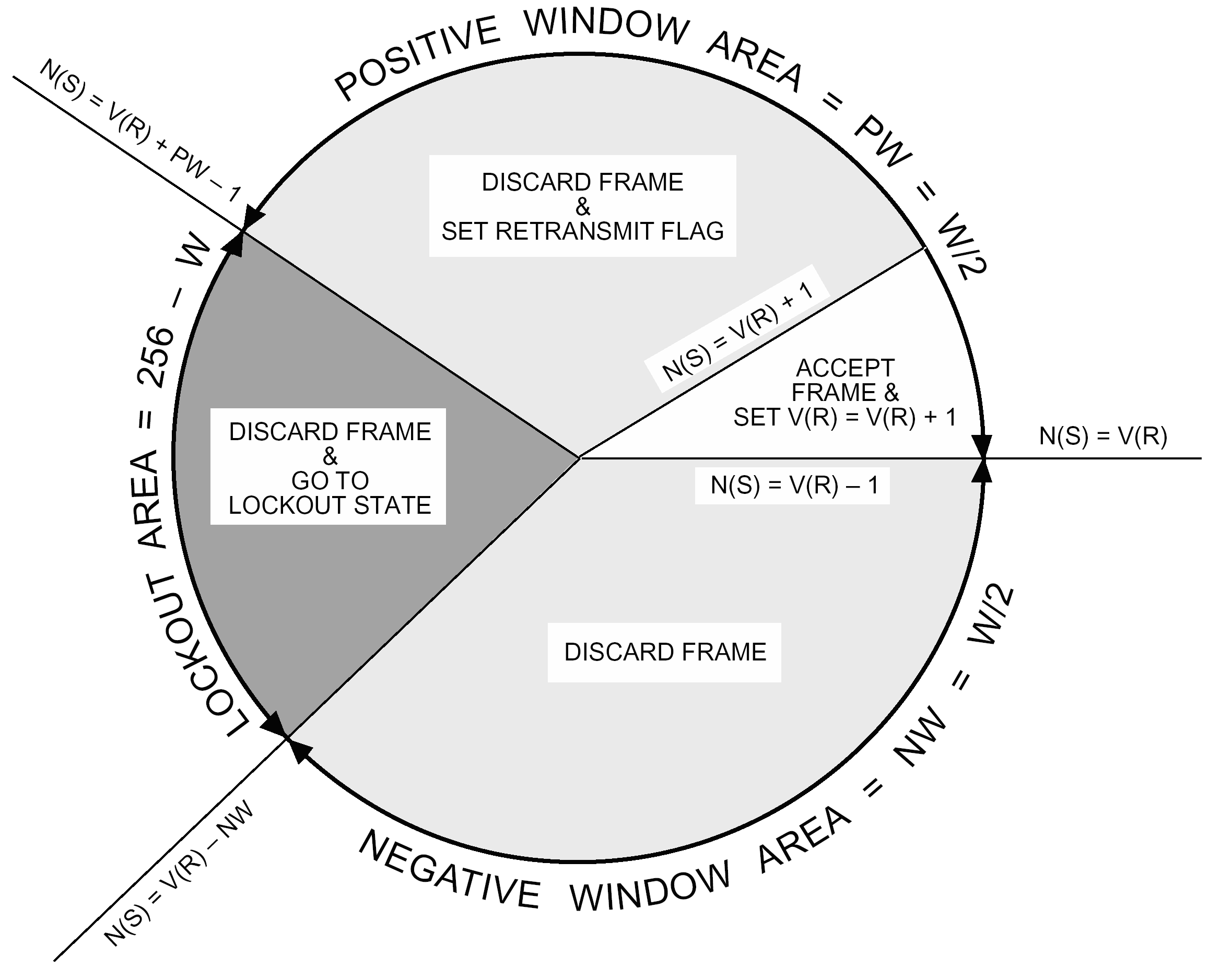 Figure 72: FARM sliding window concept
The FARM_Sliding_Window_Width, W, gives the range over which the Frame Sequence Numbers of received type-AD frames may vary without lockout occurring.
As shown in Figure 72, the FARM positive window area starts with V(R) and extends PW frames in the positive direction. The FARM negative window area starts at V(R)–1 (the number of the last accepted frame) and extends NW frames in the negative direction.
The area outside the FARM sliding window is the lockout area, which has a width of 256–W. A Frame Sequence Number, N(S), falls into the lockout area when the following conditions are met:
N(S) > V(R) + PW – 1
Equation and
N(S) < V(R) - NW
In this case, FARM-1 discards the frame, enters the Lockout state and sets the Lockout_Flag.
When N(S) falls inside the FARM sliding window, one of the following three cases occurs:
Case 1
N(S) = V(R)
The frame is in the positive window and contains the expected Frame Sequence Number; the frame is accepted. This is the case when COP-1 is operating correctly and no previous frames have been lost or discarded. It is also the case when retransmitted frames are received after they have been lost or discarded.
Case 2
N(S) > V(R)
and
N(S) V(R) + PW – 1
The frame is in the positive window and does not contain the expected Frame Sequence Number; the frame is discarded and the Retransmit_Flag is set to ‘1’, if it has not already been set to ‘1’.
This case occurs when a previous frame has been lost or discarded and any retransmission of the frame has not yet been received.
Case 3
N(S) < V(R)
and
N(S) V(R) – NW
The frame is in the negative window and is discarded without any other action being taken.
This case occurs if frames are retransmitted even though they have been accepted. This can happen, for example, if the FOP T1_Initial has been set to a too-small value or if there is a telemetry outage. It can occur during operations using the forced-retransmission mechanism.
Requirements
The value of W shall be set according to the following rules:
2 W 254
and
W is an even integer
The values of PW and NW shall be set according to the following rule:
PW = NW = W/2
The values of W, PW and NW shall be fixed for the duration of the mission except as specified in 7.2.3.8.2d.
There are no COP-1 control commands for changing the values.
For missions where commanding performance depends on different window widths for different mission phases, the values of W, PW and NW shall be fixed for a mission phase.
Special case
For a mission operating with the FOP-1 Transmission_Limit set to 1, PW may be set greater than NW, with, ultimately, NW = 0 and PW = W, where W is any integer between, and including, 1 and 256,. Thus:
PW W
and
1 W 256
and
1 PW 256
A given mission can opt to have only a single transmission of a sequence of type-AD frames in one COP-1 session (Transmission_Limit = 1), whether in the suspend/resume mode of operation or not. For such a mission, these different rules can be used for setting the sliding window variables.
Buffer Administration Variables
FARM-1 uses storage to process frames as they arrive and to contain data to be passed to the next higher sublayer. The actual storage allocation strategy is implementation dependent. However, the way FARM-1 is defined in the state table implies that certain aspects of this strategy are not implementation dependent. These are described here.
The FARM-1 state table implies the existence of the following FARM-1 buffers:
At least one front-end (i.e. input) buffer to contain one maximum-length frame, for use while FARM-1 processes the frame.
At least one back-end (i.e. output) buffer capable of receiving one maximum-length FDU (i.e. data from one frame) to be passed to the next higher sublayer.
If only one back-end buffer is provided, then an FDU from a type-BD frame has priority as defined in clause 7.5.4.
Features of COP-1 interfaces
Overview
The interactions on the COP-1 interfaces are defined as signals which are passed across the interfaces. Table 71 lists the interfaces.
In describing features of the interfaces, the other entities on the interfaces are sometimes mentioned. The following phrases are used:
The phrase “next higher sublayer” is used when discussing the transfer of FDUs on an upper interface of COP-1.
The phrase “management entities” is used to describe those parts of the system which are responsible for management functions, including the management of the sequence-controlled service and the handling of error events reported by COP-1.
The phrase “lower procedures” is used when discussing the transfer of frames on a lower interface of COP-1, and it refers to the procedures below COP-1 in the transfer sublayer. For historical reasons, the phrase “lower layer interface” (LLIF) also appears.
Table 71: COP-1 interfaces
|
Interface
|
Clause
|
|
Upper interface of COP-1 at the sending end
|
7.4
|
|
Upper interface of COP-1 at the receiving end
|
7.5
|
|
Lower interface of COP-1 at the sending end
|
7.6
|
|
Lower interface of COP-1 at the receiving end
|
7.7
|
Parameters
The definitions of the signals specify the associated parameters. The parameters are specified in an abstract sense and specify the information to be made available. The way in which this information is made available for an implementation is not constrained by the specification.
For example, a typical signal has the parameter “virtual channel identification”. The virtual channel identifier and the spacecraft identifier both form part of the identification of a virtual channel, and both values are made available to the entity that receives the signal. In a system where all virtual channels have the same spacecraft identifier, an implementation can pass the virtual channel identifier with the signal and the spacecraft identifier can already be known to the receiving entity.
In addition to the specified parameters, an implementation can provide other parameters (e.g. for controlling the configuration, monitoring performance, facilitating diagnosis, and so on).
Upper interface of COP-1 at the sending end
Overview
FOP-1 provides the following upper interfaces at the sending end:
Management of the sequence-controlled service;
FDU transfer on the sequence-controlled service;
FDU transfer on the expedited service.
Sequence-controlled service management interface
Overview
Management entities use the management interface to control the operation of COP-1 for a virtual channel. The interface includes directives, that manage the state of the sequence-controlled service and set its operating parameters, such as timer values and transmission limits.
The sequence-controlled service guarantee depends on the correct management and operation of the service. The following are examples of cases where the service guarantee does not apply:
The sequence numbers of the FOP-1 and FARM-1 are not synchronized at the start of a session.
Multiple instances of FOP-1 are sending frames at the same time to a single instance of FARM-1.
CLCWs are delivered to FOP-1 which come from the wrong spacecraft.
The management entity sends directive request signals to FOP-1 and FOP-1 sends directive notification signals containing the responses to the directives.
FOP-1 uses the asynchronous notification signal to report the status of a virtual channel to the management entity. The notification type can be Alert or Suspend.
Table 72 shows the signals defined for the sequence-controlled service management interface. In addition, FOP-1 supplies implementation-dependent status information as defined in clause 7.4.2.7.
Table 72: Signals for management interface
|
Signal
|
Type parameter
|
Clause
|
|
Directive request signal to FOP-1
|
Directive type,has values shown in Table 73
|
7.4.2.2
|
|
Directive notificationsignal from FOP-1
|
Notification type,gives response to a directive
|
7.4.2.3
|
|
Asynchronous notificationsignal from FOP-1
|
Notification type = Alert
|
7.4.2.4,7.4.2.5
|
|
Notification type = Suspend
|
7.4.2.4,7.4.2.6
|
Directive request signal
A directive request signal shall have the following parameters:
- Request identifier
- Virtual channel identification
- Directive type
- Directive qualifier. The management entity and FOP-1 shall share a common system of request identifiers for use when referring to a particular directive.
- 1 FOP-1 returns the request identifier as one of the parameters in the directive notification signal.
- 2 The system of request identifiers is implementation dependent.
The directive type shall be one of the directive types shown in Table 73. - 1 The FOP-1 actions on receipt of a directive are defined in the FOP-1 state table in the entries for events E23 to E40.
- 2 The following setup directives can be used while FOP-1 is not in state S6:
- Set FOP_Sliding_Window_Width,
- Set T1_Initial,
- Set Transmission_Limit, and
- Set Timeout_Type.
- 3 However, attention is drawn to the risk of using these directives in these circumstances. Changes are not limited to subsequent frames, but affect frames that are currently in the Sent_Queue.
The directive qualifier shall take the value appropriate to the directive type as shown in Table 73.
A directive with an invalid directive type or directive qualifier is handled as an invalid directive.
Table 73: FOP-1 directive types and qualifiers
|
Directive type
|
Directive qualifier
|
|
Initiate AD Service(without CLCW check)
|
(none)
|
|
Initiate AD Service(with CLCW check)
|
(none)
|
|
Initiate AD Service(with Unlock)
|
(none)
|
|
Initiate AD Service(with Set V(R))
|
V*(R), the new value for V(R)
|
|
Terminate AD Service
|
(none)
|
|
Resume AD Service
|
(none)
|
|
Set V(S) to V*(S)
|
V*(S), the new value for V(S)
|
|
Set FOP_Sliding_Window_Width
|
New value for width of FOP sliding window (K)
|
|
Set T1_Initial
|
New value for Timer_Initial_Value (T1_Initial)
|
|
Set Transmission_Limit
|
New value for Transmission_Limit
|
|
Set Timeout_Type
|
New value for Timeout_Type (TT)
|
Directive notification signal
A directive notification signal shall have the following parameters:
- Request identifier
- Virtual channel identification
- Notification type. Following receipt of a directive request signal, FOP1 shall asynchronously send a directive notification signal with the notification type set to one of the following responses:
- Accept Response to Directive
- Reject Response to Directive.
The response indicates whether FOP-1 tries to execute the directive.
After each Accept Response to Directive, but asynchronously from that response, FOP-1 shall send a directive notification signal with the notification type set to one of the following confirm responses:
-
Positive Confirm Response to Directive
-
Negative Confirm Response to Directive.
-
1 The confirm response indicates whether COP-1 (including FARM-1 for directives requiring receiving-end action) was able to complete the execution of the directive.
-
2 There can be a significant time period between the Accept Response to Directive and the related confirm response.
For example, an Initiate AD Service (with Unlock) directive includes sending a type-BC frame to FARM-1 and waiting for a CLCW to return. -
3 A Positive Confirm Response to Directive means that execution of the directive was successfully completed.
-
4 A Negative Confirm Response to Directive means that either the execution of the directive was not successfully completed, or it is not possible to determine whether it was successfully completed.
-
5 A Negative Confirm Response to Directive does not carry a parameter giving the reason for the failure to confirm. However, whenever a condition is detected that can give rise to the negative response, FOP-1 issues an Alert notification. The Alert provides a failure parameter.
Asynchronous notification signal
An asynchronous notification signal shall have the following parameters:
- Virtual channel identification
- Notification type
- Notification qualifier. The notification type shall be set to one of the following notifications:
- Alert notification
- Suspend notification.
Alert notification
Overview
FOP-1 issues an Alert notification following an exception or following receipt of a Terminate AD Service directive. When FOP-1 issues an Alert notification, it terminates the sequence-controlled service or any activity to initiate the sequence-controlled service, and enters Initial state (S6).
The Alert notification implies the end of the sequence-controlled service guarantee.
Requirements
When FOP-1 detects an exception condition, it shall send an asynchronous notification signal with the notification type set to indicate an Alert notification.
The notification qualifier parameter of the signal shall indicate the reason for the Alert, using one of the values given in Table 74.
In addition, an implementation can opt to include parameters giving the FOP-1 event number that caused the Alert and the FOP-1 state at the time of the event. The additional information can assist the management entities.
Following receipt of an Alert notification, the management entity should perform recovery actions to ensure that data is not lost, duplicated or erroneous.
Table 74: Reasons for an Alert notification
|
Reason
|
Causes
|
|
Alert[limit]
|
CLCW which negatively acknowledges a type-AD frame, when Transmission_Limit is set to 1
|
|
Alert[T1]
|
Timer expires when the allowed number of transmissions has been exhausted for a type-AD frame and Timeout_Type is set to ‘0’
|
|
Alert[lockout]
|
CLCW with Lockout Flag = 1 has arrived
|
|
Alert[synch]
|
CLCW with Retransmit Flag = 0 and = NN(R) has arrived, when last CLCW showed Retransmit Flag = 1
|
|
Alert[NN(R)]
|
CLCW with invalid N(R) has arrived
|
|
Alert[CLCW]
|
CLCW with Wait Flag = 1 and Retransmit Flag = 0 has arrived
|
|
Alert[LLIF]
|
FOP-1 and lower layer are out of synchronization. Lower layer rejects frame even though appropriate Out_Flag is set to Ready. (LLIF refers to the lower layer interface.)
|
|
Alert[term]
|
Terminate AD Service directive
|
Interpretation of an Alert notification
Alert[limit] and Alert[T1] can occur because of a break in the underlying physical link and can therefore be caused by problems outside the transfer sublayer.
With the exception of Alert[term], the other Alert notifications report a breakdown of the transfer sublayer protocol. This means that some part of the system is not operating to specification and therefore reports already received by the management entities can be incorrect.
In particular, an Alert notification carries the virtual channel identifier corresponding to the FOP-1 in which the error condition was detected; but, given that the protocol mechanism has broken down, the virtual channel identifier can be corrupted. A single failure can cause the same or different Alert notifications on more than one virtual channel.
Following an Alert notification, FOP-1 enters Initial state (S6). In this state, most exception conditions are ignored, so no further Alert notifications occur until the management entity causes a change of FOP-1 state by means of a directive. (An exception is Alert[LLIF], which can occur in S6.)
For example: if a CLCW with Lockout Flag = 1 causes an Alert[lockout], FOP-1 enters state S6, where all CLCWs are ignored. So later CLCWs with Lockout Flag = 1 do not cause repeated Alert[lockout] notifications.
Suspend notification
Overview
If the Transmission_Limit is reached and Timeout_Type is set to ‘1’, FOP-1 issues a Suspend notification and suspends the AD service.
When the AD service is suspended, FOP-1 enters Initial state (S6). The Sent_Queue and other FOP-1 variables are not cleared or reset. The management entity can then use the Resume AD Service directive to resume the service in the state indicated by the Suspend_State variable, SS.
By setting Timeout_Type to 1 and setting a small value of T1_Initial, FOP-1 can be forced to transmit a sequence of type-AD frames a specified number of times and then suspend its operation.
The Suspend notification notifies the management entity that the transmissions have been completed and that the operation has been suspended. A subsequent resume directive can then be used to resume the AD service, for example, once acknowledging CLCWs are available. This strategy can be useful for missions with a long round-trip delay.
The FOP-1 directives include the Terminate AD Service directive. This directive is not effective when the AD service is suspended. In this case, Accept and Positive Confirm responses are signalled for the directive, but the AD service remains suspended (e.g. Suspend_State remains different from zero, the queues are not purged).
To terminate a suspended AD service, the service can first be resumed with a Resume AD Service directive (and then a subsequent Terminate AD Service directive is effective) or initiated with one of the Initiate AD Service directives performing the Initialise action.
Requirements
When FOP-1 suspends the AD service, it shall send an asynchronous notification signal with the notification type set to indicate a Suspend notification.
- 1 The notification qualifier parameter of the signal is not used for a Suspend notification.
- 2 The Suspend_State variable, SS, takes a value corresponding to the state FOP-1 was in at the time it was suspended.
Additional status information
Additional status information should be passed from FOP-1 to the management entity for use in performance monitoring and problem diagnosis.
The additional status information is implementation dependent.
Sequence-controlled service data transfer interface
Overview
The function of the sequence-controlled service is to accept FDUs from the next higher sublayer at the sending end and deliver them to the next higher sublayer at the receiving end. The service transfers FDUs via type-AD frames.
An automatic retransmission mechanism prevents any gaps in the received stream of frames and, as described in clause 7.1.5.2, the service ensures a high probability of success that:
no FDU is lost, and
no FDU is duplicated, and
no FDU is delivered out of sequence.
This service guarantee applies to a virtual channel for the duration of a service session. From the point of view of the management entity, a session begins when the management entity receives a Positive Confirm Response to Directive for one of the Initiate AD Service directives. A session ends when the management entity receives an Alert notification.
The signals defined for the sequence-controlled service data transfer interface are given in Table 75.
Table 75: Signals for sequence-controlled service data transfer interface
|
Signal
|
Direction
|
Clause
|
|
Request to transfer FDU (AD service) signal
|
To FOP1
|
7.4.3.2
|
|
Transfer notification (AD service)signal
|
From FOP-1
|
7.4.3.3
|
The next higher sublayer uses the request to transfer FDU (AD service) signal to request FOP-1 to transfer an FDU on the sequence-controlled service. FOP-1 returns a transfer notification (AD service) signal containing a response which indicates acceptance or rejection of the request by FOP-1. If the response indicates acceptance, then FOP-1 later returns another response, called a confirm response. The confirm response provides information on the success or failure of the transfer.
A flow control mechanism operates on the interface between the next higher sublayer and FOP-1. When the next higher sublayer issues an FDU transfer request for the AD service, it then waits until it receives an accept or reject response before issuing another FDU transfer request for the AD service on the same virtual channel.
If FOP-1 receives a transfer request but is unable to transmit the FDU immediately, then it delays signalling acceptance of the request, even though it places the FDU in its Wait_Queue. At this time the FDU is deemed to be still under the control of the next higher sublayer. Later, when FOP-1 has transfer capacity available, it signals acceptance of the request, and the FDU is then deemed to be under the control of FOP-1.
From the point of view of the next higher sublayer, once a request has been accepted, the FDU is in a “grey area”. The next higher sublayer does not know if the FDU has been successfully transferred. If the next higher sublayer then receives a positive confirm response, the uncertainty is removed: the FDU has been successfully transferred.
However, if the next higher sublayer receives a negative confirm response, the uncertainty remains: the FDU can has been successfully transferred or not. Therefore, a negative confirm response signals a break in the sequence-controlled service guarantee.
If a transfer request has not yet been accepted, the FDU is deemed to be still under the control of the next higher sublayer and is not covered by the sequence-controlled service guarantee. Once FOP1 detects a problem leading to a break in the sequence-controlled service guarantee, it rejects the waiting transfer request. Therefore, an FDU which has not been accepted can never be in the “grey area”.
Request to transfer FDU (AD service) signal
A request to transfer FDU (AD Service) signal shall have the following parameters:
- Request identifier
- Virtual channel identification
- FDU. The next higher sublayer and FOP-1 shall share a common system of request identifiers for use when referring to a particular transfer request.
- 1 The request identifier therefore also refers to the particular FDU belonging to the request.
- 2 FOP-1 returns the request identifier as one of the parameters in the transfer notification (AD service) signals.
- 3 The system of request identifiers is implementation dependent.
The system of request identifiers shall be able to handle multiple requests awaiting confirm responses at the same time.
Transfer notification (AD service) signal
A transfer notification (AD service) signal shall have the following parameters:
- Request identifier
- Virtual channel identification
- Notification type. Following receipt of a request to transfer FDU (AD service), FOP-1 shall asynchronously send a transfer notification signal with the notification type set to one of the following responses:
- Accept Response to Request to Transfer FDU (AD Service)
- Reject Response to Request to Transfer FDU (AD Service).
The next higher sublayer shall not issue another request to transfer FDU (AD service) for the same virtual channel until the current request is accepted or rejected.
After each Accept Response to Request to Transfer FDU (AD service), but asynchronously from that response, FOP-1 shall send a transfer notification signal with the notification type set to one of the following confirm responses: - Positive Confirm Response to Request to Transfer FDU (AD Service)
- Negative Confirm Response to Request to Transfer FDU (AD Service).
- 1 The Positive Confirm Response to Request to Transfer FDU (AD Service) confirms that the FDU arrived at the receiving end and was acknowledged by a CLCW.
- 2 FOP-1 signals a Negative Confirm Response to Request to Transfer FDU (AD Service) when it is unable to guarantee that an FDU arrived at the receiving end, despite retry attempts. The negative confirm response does not carry a parameter giving the reason for the failure to confirm the requested data transfer service. However, whenever a condition is detected which can give rise to a negative confirm response, FOP-1 issues an Alert notification.
Expedited service data transfer interface
Overview
The function of the expedited service is to accept FDUs from the next higher sublayer at the sending end and deliver them to the next higher sublayer at the receiving end. The service transfers FDUs via type-BD frames.
As described in clause 7.1.5.3, there is no automatic retransmission mechanism; there is only one transmission for each type-BD frame. COP-1 does not include any error recovery to replace a type-BD frame lost in transmission.
Although the BD service carries the name “expedited”, it is does not provide a faster method for inserting a frame for immediate delivery into a stream of frames. If the link currently supports a reliable AD service then AD mode is used in such cases.
The signals defined for the expedited service data transfer interface are given in Table 76.
Table 76: Signals for expedited service data transfer interface
|
Signal
|
Direction
|
Clause
|
|
Request to transfer FDU (BD service) signal
|
To FOP1
|
7.4.4.3
|
|
Transfer notification (BD service)signal
|
From FOP-1
|
7.4.4.4
|
The next higher sublayer uses the request to transfer FDU (BD service) signal to request FOP-1 to transfer an FDU on the expedited service. FOP-1 returns a transfer notification (BD service) signal containing a response which indicates acceptance or rejection of the request by FOP-1.
Requirements for use of the expedited service
The operational conditions under which the expedited service can be used shall be defined for each mission.
In implementations where FARM-1 uses the same single back-end buffer for FDUs carried by type-AD and type-BD frames, the sending-end management entity shall terminate any ongoing AD service before starting a BD service on the same virtual channel.
As described in clause 7.5.4, this buffer implementation can cause frames to be overwritten.
Request to transfer FDU (BD Service) signal
A request to transfer FDU (BD Service) signal shall have the following parameters:
- Request identifier
- Virtual channel identification
- FDU. The next higher sublayer and FOP-1 shall share a common system of request identifiers for use when referring to a particular transfer request.
- 1 The request identifier therefore also refers to the particular FDU belonging to the request.
- 2 FOP-1 returns the request identifier as one of the parameters in the transfer notification (BD service) signal.
- 3 The system of request identifiers is implementation dependent.
Transfer notification (BD service) signal
A transfer notification (BD service) signal shall have the following parameters:
- Request identifier
- Virtual channel identification
- Notification type. Following receipt of a request to transfer FDU (BD Service), FOP-1 shall asynchronously send a transfer notification signal with the notification type set to one of the following responses:
- Accept Response to Request to Transfer FDU (BD Service)
- Reject Response to Request to Transfer FDU (BD Service).
- 1 If the sending-end lower procedures are capable of accepting the type-BD frame, the request is accepted and the FDU is transmitted. If the lower procedures cannot accept the type-BD frame, the request is rejected; there is no Wait_Queue for type-BD frames.
- 2 As no error recovery is performed by COP-1 for a type-BD frame, no copy of the data is kept by FOP-1 and no confirmation of acceptance of the frame by the receiving end is signalled on the interface.
Upper interface of COP-1 at the receiving end
Overview
At the receiving end, FARM-1 uses an FDU Arrived Indication to signal the arrival of an FDU to the next higher sublayer.
FARM-1 delivers the data in a back-end (output) buffer containing the accepted FDU. This Standard does not specify the mechanism used by the next higher sublayer, the management entities and FARM-1 for buffer management. However, the following aspects are specified:
Implementation of the wait system, and
The special case of a single back-end buffer.
Buffer management mechanism
The buffer management mechanism shall ensure that FARM-1 always knows whether a back-end buffer is available.
The buffer management mechanism shall supply a buffer release signal to FARM-1.
- 1 The buffer release signal causes event E10 in the FARM-1 state table. The signal indicates to FARM-1 that a back-end buffer is now available.
- 2 A back-end buffer is unavailable if it contains any FDU data that has not yet been read by the next higher sublayer.
The wait system
Overview
The wait system is part of the sequence-controlled service. It is a flow control mechanism that enables the buffer management mechanism to signal that the receiving end is not able to cope with the incoming rate of data.
FARM-1 enters the Wait state (S2) when it receives a type-AD frame but is unable to deliver the FDU contained in it to the next higher sublayer. The Wait Flag in a CLCW notifies FOP-1 that FARM-1 is in the Wait state. FARM-1 leaves the Wait state upon receipt of a buffer release signal from the buffer management mechanism.
When FARM-1 receives a valid type-AD frame with the expected sequence number, the action depends on the availability of a back-end buffer. The general principle is: if there is a buffer available, it is used, and if not, the frame is discarded.
A valid, in-sequence, type-AD frame arrives
If FARM-1 is in state S1 and a back-end buffer is available, then:
- FARM-1 shall copy the FDU from the frame into the back-end buffer.
- FARM-1 shall signal an FDU Arrived Indication, with the FDU aborted indication not set. If FARM-1 is in state S1 and a back-end buffer is not available, then:
- FARM-1 shall discard the type-AD frame.
- FARM-1 shall not signal an FDU Arrived Indication.
- 1 This clause corresponds to events E1 and E2 for state S1 in the FARM-1 state table. The state table defines additional actions for these events in S1.
- 2 This clause only applies to the behaviour when FARM-1 is in state S1. The FARM-1 state table defines the FARM-1 behaviour when these events occur in states S2 and S3.
- 3 The FDU Arrived Indication is defined in clause 7.5.5.
Single back-end buffer
Overview
The receiving end can have a FARM-1 implementation that provides only one back-end buffer for a virtual channel. The requirements in clause 7.5.4.2 apply in this case. In particular, the requirements specify the actions when the buffer is unavailable. The general principle is that when FARM-1 receives a valid type-BD frame, the new frame has priority.
Such an implementation can provide increased reliability through reduced complexity and lower resource consumption.
Requirement in clauses 7.4.4.2 and 7.4.4.2b also applies in this case.
The specification in clause 7.5.4.2 applies for all three FARM-1 states: S1, S2 and S3.
A valid type-BD frame arrives
If the back-end buffer is available, then FARM-1 shall:
- Copy the FDU from the frame into the back-end buffer.
- Signal an FDU Arrived Indication, with the FDU aborted indication not set. If the back-end buffer is not available, then FARM-1 shall:
- Copy the FDU from the frame into the back-end buffer, overwriting (and so erasing) the previous FDU.
- Signal an FDU Arrived Indication, with the FDU aborted indication set.
- 1 The previous FDU can have been received in a type-AD or a type-BD frame.
- 2 The previous FDU is erased without any indication to the ground in the CLCW. However, if the FDU was from a type-AD frame, it has already been acknowledged in a CLCW. This sequence of events therefore invalidates the sequence-controlled service guarantee.
FDU Arrived Indication
When FARM-1 has an FDU to deliver to the next higher sublayer, it shall signal an FDU Arrived Indication.
A type-BC frame contains a COP-1 control command which is executed inside FARM-1. It does not contain an FDU and does not result in an FDU Arrived Indication.
An FDU Arrived Indication shall carry the following parameters:
- FDU
- Virtual channel identification
- FDU aborted indication
- 1 The setting of the FDU aborted indication is specified in clauses 7.5.3.2 and 7.5.4.2 .
- 2 In addition, the parameters can include a type identifier to indicate which service (AD or BD) was used to transfer the FDU.
Lower interface of COP-1 at the sending end
Overview
The signals defined for the lower interface of FOP-1 are provided in Table 77.
Table 77: Signals for the interface of FOP-1 to the lower procedures
|
Signal
|
Direction
|
Clause
|
|
Transmit Request for Frame signal
|
From FOP1
|
7.6.2
|
|
Abort request signal
|
From FOP-1
|
7.6.3
|
|
Response signal
|
To FOP-1
|
7.6.4
|
FOP-1 uses a transmit request for frame signal to request the lower procedures to transfer data. Following receipt of a transmit request for frame signal, the lower procedures asynchronously send a response signal to indicate acceptance or rejection of the request.
FOP-1 uses an Abort request signal to request the lower procedures to delete queued frames. The extent of the action following an Abort request is implementation dependent; it can affect all sublayers and layers of the sending end of the telecommand link below FOP-1. The purpose of the Abort request is to prevent data being transmitted unnecessarily and therefore to preserve resources on the link. The lower procedures do not return any response to the Abort request.
Transmit Request for Frame signal
A Transmit Request for Frame signal shall have the following parameters:
- Type identifier (AD, BD or BC)
- Virtual channel identification
- Other frame contents including:
- Frame Sequence Number, N(S), for type-AD frames
- Transfer Frame Data Field contents (FDU or COP-1 control command)
The parameters may also include the value for the Transfer Frame Version Number field of the frame, or alternatively, this value may already be known to the lower procedures.
Clause 6.2.2.2 defines only one value for the Transfer Frame Version Number.
For each frame type (AD, BD or BC), at most one transmit request shall be outstanding, i.e. awaiting a response.
FOP1 uses the AD_Out_Flag, BD_Out_Flag and BC_Out_Flag defined in clause 7.2.2.7 to keep track of outstanding requests.
Abort request signal
An Abort request signal shall have the following parameter: Virtual channel identification.
On receipt of an Abort request the lower procedures should delete any type-BC or type-AD frames on that virtual channel that are awaiting transmission within the lower procedures or the sublayers and layers below.
- 1 Type BD frames are not deleted as a result of an Abort request.
- 2 Any action by the sublayers and layers below following receipt of an Abort request is implementation dependent.
If a frame (in the form of a CLTU) is currently being transmitted, the frame shall not be deleted and the transmission shall be allowed to continue to the end of the CLTU.
Response signal
A Response signal shall have the following parameters:
- Virtual channel identification
- Response type. Following receipt of a Transmit Request for Frame signal from FOP-1, the lower procedures shall asynchronously send a Response signal with the response type set to one of the following values:
- AD_Accept
- AD_Reject
- BC_Accept
- BC_Reject
- BD_Accept
- BD_Reject.
- 1 The response indicates acceptance or rejection of a request by the lower procedures. For example, AD_Accept means acceptance of a transmit request for a frame with type identifier AD.
- 2 The lower procedures delay sending an accept response until they are ready to receive the next transmit request for that frame type on that virtual channel.
- 3 The responses cause events E41 to E46 in the FOP-1 state table.
Lower interface of COP-1 at the receiving end
Overview
The Valid Frame Arrived Indication is used to deliver a frame from the lower procedures to FARM-1. No signals are specified from FARM-1 to the lower procedures.
Valid Frame Arrived Indication
When the lower procedures have a frame to deliver to FARM-1, they shall signal a Valid Frame Arrived Indication to FARM-1.
The Valid Frame Arrived Indication shall use one of the following procedures to deliver data to FARM-1:
- The lower procedures deliver the following parameters:
- Type identifier (AD, BD or BC)
- Virtual channel identification
- Frame Sequence Number, N(S), for type-AD frames
- Transfer Frame Data Field contents (FDU or COP-1 control command)
- The lower procedures deliver the complete frame, including the header.
The frame contains all the information in the parameters listed in clause 7.7.2.
Format of COP-1 control commands
Overview
Two COP-1 control commands are defined: Unlock and Set V(R). The commands are generated by FOP-1 following receipt of an Initiate AD Service (with Unlock) directive or an Initiate AD Service (with Set V(R)) directive.
The commands are transmitted from FOP-1 to FARM-1 in the Transfer Frame Data Field of type-BC frames, as defined in clause 6.2.3.
General
The Transfer Frame Data Field of a type-BC frame shall contain exactly one COP-1 control command.
The COP-1 control command contained in the Transfer Frame Data Field of a type-BC frame shall be one of the following:
- Unlock, or
- Set V(R).
All other uses of the Transfer Frame Data Field of a type-BC frame are reserved for future application.
Unlock
An Unlock control command shall consist of a single octet containing “all zeroes”.
Set V(R)
A Set V(R) control command shall consist of three octets.
The first octet of a Set V(R) control command shall contain the binary value ‘10000010’.
The second octet of a Set V(R) control command shall contain “all zeroes”.
The third octet of a Set V(R) control command shall contain the new value for V(R).
On receipt of the Set V(R) control command, FARM-1 sets the Receiver_Frame_Sequence_Number, V(R), to the value contained in the third octet.
Actions
Format of the state tables
Overview
For ease of reference, the state tables and state transition diagrams have all been placed together at the end of Clause 7.
Each state table describes the processing for one independent virtual channel.
The columns of the state table correspond to the states of the protocol machine. The rows correspond to events which cause actions and state changes.
The table entry at the intersection of a row with a column shows the actions and state change that are performed when the related event occurs in the related state. State transitions are indicated by state numbers in parentheses; thus (S2) indicates that the protocol machine goes to state number 2.
The use of the state tables is illustrated in Figure 73.
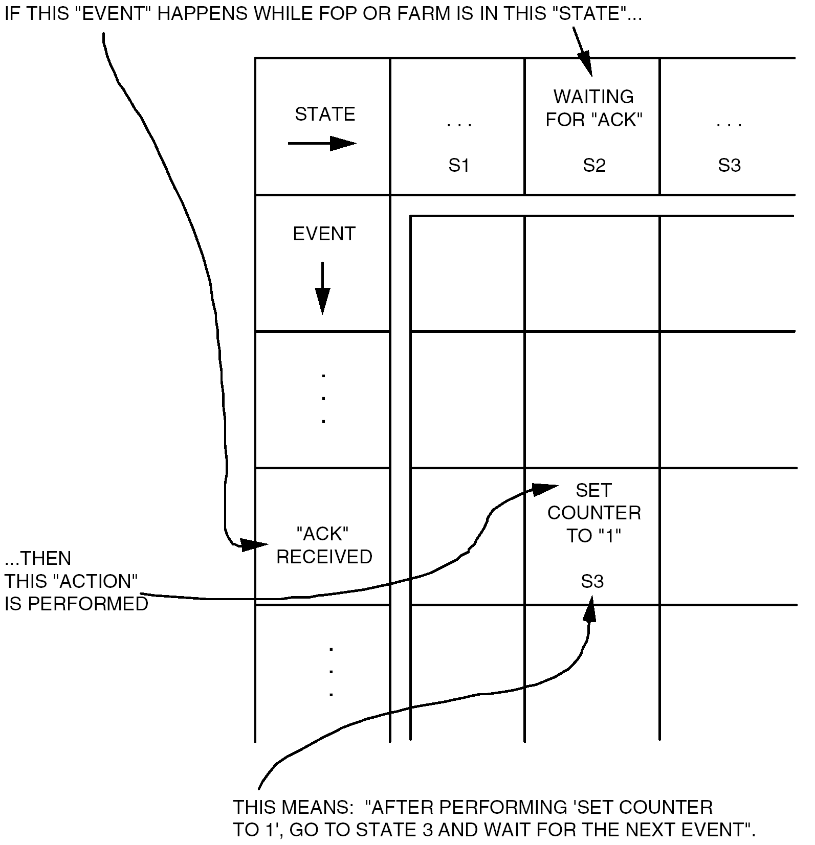 Figure 73: State table format
Execution
The actions for a table entry shall be completed before the state change is performed.
The actions and state change for one table entry shall be completed before processing the next event.
FOP-1
Overview
Table 78 contains the FOP-1 state table.
The protocol machine described in this Standard is the updated version, sometimes referred to as FOP-1 revision B or simply FOP-1B. The non-sequential numbering of some events arises from the revision.
The FOP-1 table is large and the state transitions complex. Therefore, three state transition diagrams are provided. The first one, in Figure 76, only shows the state changes relating to the main protocol. This covers the automatic handling of retransmissions and flow control using the timer, the Retransmit Flag and the Wait Flag. It does not cover initialisation, nor does it cover any events leading to an Alert or Suspend notification.
The second state transition diagram, in Figure 77, shows the initialisation protocol, which is used to initiate and terminate a session using the AD Service. The diagram groups the main protocol States (S1), (S2) and (S3) into a single circle. Apart from Alert[term], all events leading to an Alert or Suspend notification are included under “Exceptions”.
Finally, there is a complete FOP-1 state transition diagram in Figure 78.
Some sequences of actions appear in several entries in the state table. Each sequence has a name, such as “Transmit type-AD frame”, and the name is used in the table. The definitions of the sequences of actions are given in clauses 7.9.2.4 to 7.9.2.19
In the FOP-1 state table, references to the Lockout Flag, Wait Flag, Retransmit Flag or N(R) pertain to the values in the current CLCW.
Arrival of a CLCW
When a CLCW arrives, some of its fields are checked, including:
Control Word Type
CLCW Version Number
COP in Effect
Virtual Channel Identification
Spare fields in bits14-15 and 23.
If any of these fields do not contain the expected values, the CLCW is considered invalid (event E15 in the FOP-1 state table).
Otherwise, the following fields in the CLCW are checked to determine the event:
Lockout Flag
N(R)
Retransmit Flag
Wait Flag.
Modulo 256 arithmetic for FOP-1
All arithmetic concerning the COP-1 sequence number and the associated fields V(S), N(R) and NN(R) shall be performed modulo 256.
The COP-1 sequence number is an 8-bit field.
All comparisons concerning the COP-1 sequence number and the associated fields V(S), N(R) and NN(R) shall take account of the valid ranges of the sequence number.
In cases where K (FOP_Sliding_Window_Width) is greater then 127, a conventional modulo-256 comparison can deliver the wrong result.
Purging the Sent_Queue
Purging the Sent_Queue shall include the following for each frame on the queue:
- For a type-AD frame, generating a Negative Confirm Response to Request to Transfer FDU (AD Service).
- For a type-BC frame, generating a Negative Confirm Response to Directive.
- Deleting the frame.
Purging the Sent_Queue occurs as part of the termination or initialisation of the AD Service. It occurs at initialisation because FOP-1 can reach S6 via a Suspend action.
Purging the Wait_Queue
If the Wait_Queue is empty, no processing shall be performed for purging the Wait_Queue.
If the Wait_Queue is not empty, purging the Wait_Queue shall include:
- Generating a Reject Response to Request to Transfer FDU (AD Service) for the FDU on the Wait_Queue;
- Removing the FDU from the Wait_Queue.
Transmit type-AD frame
Transmit type-AD frame shall include the following:
- Inserting the current value of V(S) into the N(S) field of the frame and then incrementing V(S).
- Adding the master copy of the frame to the Sent_Queue, with the To_Be_Retransmitted_Flag set to ‘0’.
- If the Sent_Queue was previously empty, setting the Transmission_Count to 1.
- Starting the timer.
- Setting the AD_Out_Flag to Not_Ready.
- Passing a copy of the type-AD frame to the lower procedures as a parameter of a Transmit Request for Frame, with type identifier set to AD.
Transmit type-AD frame (i.e. for the sequence-controlled service) includes all the functions to prepare a frame for transmission.
Transmit type-BC frame
Transmit type-BC frame shall include the following:
- Adding the master copy of the frame to the Sent_Queue, with the To_Be_Retransmitted_Flag set to ‘0’.
- Setting the Transmission_Count to 1.
- Starting the timer.
- Setting the BC_Out_Flag to Not_Ready.
- Passing a copy of the type-BC frame to the lower procedures as a parameter of a Transmit Request for Frame, with type identifier set to BC.
- 1 Transmit type-BC frame (i.e. for a COP-1 control command) includes all the functions to prepare a frame for transmission.
- 2 When a type-BC frame is added to the Sent_Queue, the queue was previously empty.
Transmit Unlock type-BC frame
Transmit Unlock type-BC frame shall include the following:
- Creating a new frame with an Unlock control command in the Transfer Frame Data Field.
- Performing the Transmit type-BC frame action defined in clause 7.9.2.7 for the frame.
Transmit Set V(R) type-BC frame
Transmit Set V(R) type-BC frame shall include the following:
- Creating a new frame with a Set V(R) control command in the Transfer Frame Data Field.
- Performing the Transmit type-BC frame action defined in clause 7.9.2.7 for the frame.
Transmit type-BD frame
Transmit type-BD frame shall include the following:
- Setting the BD_Out_Flag to Not_Ready.
- Passing a copy of the type-BD frame to the lower procedures as a parameter of a Transmit Request for Frame, with type identifier set to BD.
Transmit type-BD frame (i.e. for the expedited service) includes all the functions to prepare the frame for transmission.
Initiate AD retransmission
Initiate AD retransmission shall include the following:
- Passing an Abort request to the lower procedures.
- Incrementing the Transmission_Count.
- Starting the timer.
- Setting the To_Be_Retransmitted_Flag for each frame on the Sent_Queue.
When an initiate AD retransmission occurs, the Sent_Queue consists of one or more type-AD frames.
Initiate BC retransmission
Initiate BC retransmission shall include the following:
- Passing an Abort request to the lower procedures.
- Incrementing the Transmission_Count.
- Starting the timer.
- Setting the To_Be_Retransmitted_Flag for the frame on the Sent_Queue.
When an initiate BC retransmission occurs, the Sent_Queue consists of one type-BC frame.
Remove acknowledged frames from Sent_Queue
Remove acknowledged frames from Sent_Queue shall include the following:
- Generating a Positive Confirm Response to Request to Transfer FDU (AD Service) for each acknowledged frame, and deleting the frame.
- Updating the value of NN(R).
- Setting the Transmission_Count to 1.
Alert
Alert shall include the following:
- Cancelling the timer.
- Purging the Sent_Queue.
- Purging the Wait_Queue.
- Issuing an Alert notification in accordance with clause 7.4.2.5.
Look for directive
Look for directive shall include the actions shown in Figure 74.
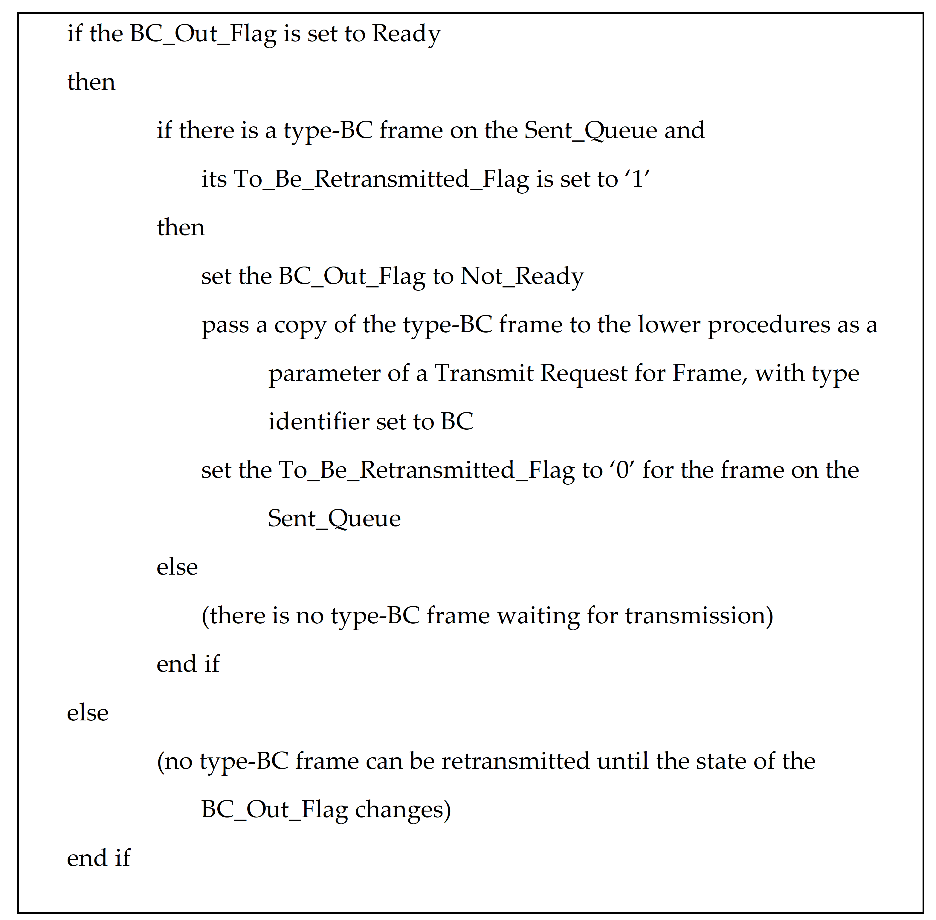 Figure 74: Actions for look for directive
Look for FDU
Look for FDU shall include the actions shown in Figure 75.
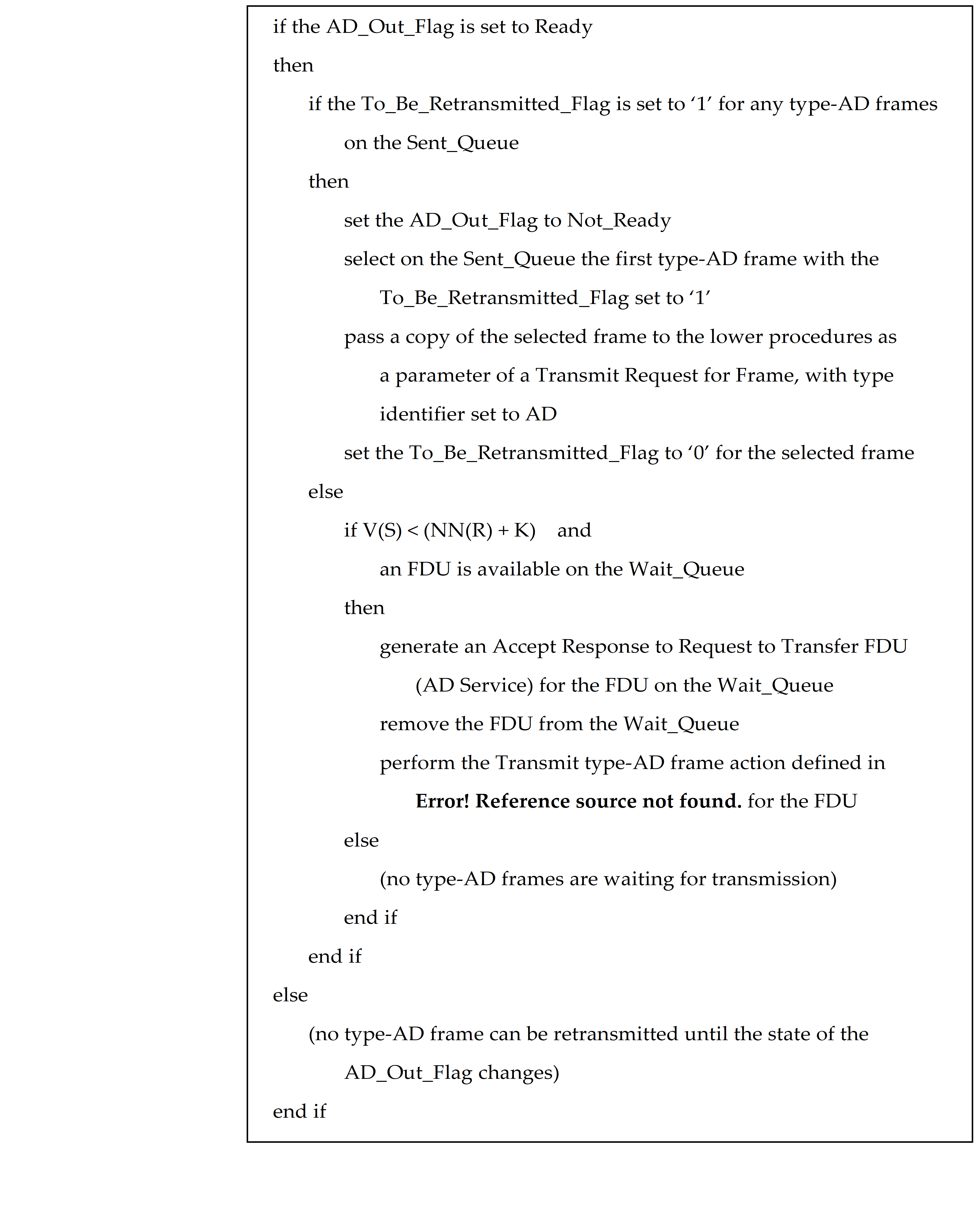 Figure 75: Actions for look for FDU
Initialise
Initialise shall include the following:
- Purging the Sent_Queue.
- Purging the Wait_Queue.
- Setting the Transmission_Count to 1.
- Setting Suspend_State (SS) to 0.
Suspend
Suspend shall include issuing a Suspend notification in accordance with clause 7.4.2.6.
Resume
Resume shall include the following:
- Starting the timer.
- Setting Suspend_State (SS) to 0.
FARM-1
Overview
The FARM-1 state table is given in Table 79, and a FARM-1 state transition diagram is represented in Figure 79.
FARM-1 constantly generates a standard report, the CLCW, which is made available to the spacecraft telemetry system at regular intervals (event E11 in the FARM-1 state table).
Sub clauses 7.9.3.2 to 7.9.3.6 contain provisions on some of the events and actions in the tables.
Modulo 256 arithmetic for FARM-1
All arithmetic concerning the COP-1 sequence number and the associated fields V(R), N(S), PW and NW shall be performed modulo 256.
The COP-1 sequence number is an 8-bit field.
All comparisons concerning the COP-1 sequence number and the associated fields V(R), N(S), PW and NW shall take account of the valid ranges of the sequence number.
In cases where PW or NW is greater then 127, a conventional modulo-256 comparison can deliver the wrong result.
Frame arrives
Events E1 to E9 happen when FARM-1 receives a Valid Frame Arrived Indication from the lower procedures as defined in clause 7.7.2. The frame has already been checked by the frame header validation procedure defined in clause 6.8.
FARM-1 uses the frame type (AD, BC or BD) and frame contents to determine the event.
For a type-BC frame, FARM-1 checks the control command in the Transfer Frame Data Field. A valid control command causes event E7 or E8, otherwise the frame causes event E9.
Accept for a type-AD frame
FARM-1 only accepts a type-AD frame if there is a back-end buffer available (event E1). When no back-end buffer is available (event E2), the frame is discarded. See clause 7.5.3.2.
Accept for a type-BD frame
FARM-1 always accepts a valid type-BD frame. The FDU from the frame is placed in the back-end buffer even if the buffer is not empty. See clause 7.5.4.2.
Execution of control commands
Events E7 and E8 are concerned with the execution of the COP-1 control commands, Unlock and Set V(R).
If a Set V(R) command arrives when FARM-1 is in Lockout state (S3), the command is not executed. (In this case, an Unlock command can be used to change the FARM-1 state so that a Set V(R) can be executed.) However, receipt of the frame is accounted for by means of the FARM-B_Counter since the frame contains a valid control command.
The Unlock and Set V(R) control commands result from initiate directives in FOP-1, and therefore can indicate a break in the sequence of sequence-controlled frames. The execution of a control command only resets the state of FARM-1. Therefore, the data management functions of the management entities can also include recovery actions, for example, to purge or reset buffers. Any mechanism to handle this case is implementation dependent and is beyond the scope of this Standard.
Table 78: FOP-1 state table
|
State Name |
ACTIVE |
RETRANSMIT WITHOUT WAIT |
RETRANSMIT WITH WAIT |
INITIALISING WITHOUT BC FRAME |
INITIALISING WITH BC FRAME |
INITIAL |
|
Main Feature of State |
Last CLCW showed: Lockout Flag = 0, Retransmit Flag = 0, Wait Flag = 0 |
Last CLCW showed: Lockout Flag = 0, Retransmit Flag = 1, Wait Flag = 0 |
Last CLCW showed: Lockout Flag = 0, Retransmit Flag = 1, Wait Flag = 1 |
Initiate AD Service (with CLCW check) Directive received and “clean” status not seen since |
frame transmitted and “clean” status not seen since |
Not configured for AD Service |
|
State Number |
S1 |
S2 |
S3 |
S4 |
S5 |
S6 |
|
Event Conditions |
|
|
|
|
Event Number |
|
|
|
|
|
|
|
|
|
CLCW arrives formed from a valid COP-1 pattern |
Lockout Flag = 0 |
N(R) = V(S) i.e.: Valid N(R) and all outstanding type AD frames acknowledged |
Retransmit Flag = 0 |
Wait Flag = 0 |
N(R) = NN(R) i.e.: no new frames acknowledged |
E1 |
|
Ignore |
Alert [synch] |
Alert [synch] |
Confirm, Cancel Timer |
Confirm, Release copy of type BC frame, Cancel Timer |
Ignore |
|
|
(S1) |
(S6) |
(S6) |
(S1) |
(S1) |
(S6) |
|||||||
|
N(R) < > NN(R) i.e.: some new frames acknowledged |
E2 |
|
Remove acknowledged frames from Sent_Queue, Cancel Timer, Look for FDU |
Remove acknowledged frames from Sent_Queue, Cancel Timer, Look for FDU |
Remove acknowledged frames from Sent_Queue, Cancel Timer, Look for FDU |
Not Applicable |
Not Applicable |
Ignore |
|||||
|
|
(S1) |
(S1) |
(S1) |
|
|
(S6) |
|||||||
|
Wait Flag = 1 |
E3 |
|
Alert [CLCW] |
Alert [CLCW] |
Alert [CLCW] |
Alert [CLCW] |
Alert [CLCW] |
Ignore |
|||||
|
|
(S6) |
(S6) |
(S6) |
(S6) |
(S6) |
(S6) |
|||||||
|
Retransmit Flag = 1 |
E4 |
|
Alert [synch] |
Alert [synch] |
Alert [synch] |
Alert [synch] |
Ignore |
Ignore |
|||||
|
|
(S6) |
(S6) |
(S6) |
(S6) |
(S5) |
(S6) |
|||||||
(Cont’d)
Table 78: FOP-1 state table (part 2)
|
|
|
|
|
|
|
State Name |
ACTIVE |
RETRANSMIT WITHOUT WAIT |
RETRANSMIT WITHWAIT |
INITIALISING WITHOUT BC FRAME |
INITIALISING WITH BC FRAME |
INITIAL |
|||
|
|
|
|
|
|
|
State Number |
S1 |
S2 |
S3 |
S4 |
S5 |
S6 |
|||
|
Continued: CLCW arrives formed from a valid COP-1 pattern |
Continued: Lockout Flag = 0 |
N(R) < V(S) and N(R) NN(R) i.e.: Valid N(R) and some outstanding type AD frames not yet acknowledged |
Retransmit Flag = 0 |
Wait Flag = 0 |
N(R) = NN(R) i.e.: no new frames acknowledged |
E5 |
|
Ignore |
Alert [synch] |
Alert [synch] |
Not Applicable |
Not Applicable |
Ignore |
||
|
|
(S1) |
(S6) |
(S6) |
|
|
(S6) |
|||||||||
|
N(R) < > NN(R) i.e.: some new frames acknowledged |
E6 Rev.B |
|
Remove acknowledged frames from Sent_Queue, Look for FDU |
Remove acknowledged frames from Sent_Queue, Look for FDU |
Remove acknowledged frames from Sent_Queue, Look for FDU |
Not Applicable |
Not Applicable |
Ignore |
|||||||
|
|
(S1) |
(S1) |
(S1) |
|
|
(S6) |
|||||||||
|
Wait Flag = 1 |
E7 Rev.B |
|
Alert [CLCW] |
Alert [CLCW] |
Alert [CLCW] |
Not Applicable |
Not Applicable |
Ignore |
|||||||
|
|
(S6) |
(S6) |
(S6) |
|
|
(S6) |
|||||||||
|
Retransmit Flag = 1 |
TransmissionLimit = 1 |
N(R) < > NN(R) i.e.: some new frames acknowledged |
E101 |
|
Remove acknowledged frames from Sent_Queue Alert [limit] |
Remove acknowledged frames from Sent_Queue Alert [limit] |
Remove acknowledged frames from Sent_Queue Alert [limit] |
Not Applicable |
Not Applicable |
Ignore |
|||||
|
|
(S6) |
(S6) |
(S6) |
|
|
(S6) |
|||||||||
|
N(R) = NN(R) i.e.: no new frames acknowledged |
E102 |
|
Alert [limit] |
Alert [limit] |
Alert [limit] |
Not Applicable |
Not Applicable |
Ignore |
|||||||
|
|
(S6) |
(S6_ |
(S6) |
|
|
(S6) |
|||||||||
|
Transmission Limit > 1 |
N(R) < > NN(R) i.e.: some new frames acknowl- edged |
Wait Flag = 0 |
E8 Rev.B |
|
Remove acknowledged frames from Sent_Queue, Initiate AD Retransmission, Look for FDU |
Remove acknowledged frames from Sent_Queue, Initiate AD Retransmission, Look for FDU |
Remove acknowledged frames from Sent_Queue, Initiate AD Retransmission, Look for FDU |
Not Applicable |
Not Applicable |
Ignore |
|||||
|
|
(S2) |
(S2) |
(S2) |
|
|
(S6) |
|||||||||
|
Wait Flag = 1 |
E9 Rev.B |
|
Remove acknowledged frames from Sent_Queue |
Remove acknowledged frames from Sent_Queue |
Remove acknowledged frames from Sent_Queue |
Not Applicable |
Not Applicable |
Ignore |
|||||||
|
|
(S3) |
(S3) |
(S3) |
|
|
(S6) |
|||||||||
(Cont’d)
Table 78: FOP-1 state table (part 3)
|
|
|
|
|
|
|
State Name |
ACTIVE |
RETRANSMIT WITHOUT WAIT |
RETRANSMIT WITHWAIT |
INITIALISING WITHOUT BC FRAME |
INITIALISING WITH BC FRAME |
INITIAL |
||||||||||||||||||
|
|
|
|
|
|
|
State Number |
S1 |
S2 |
S3 |
S4 |
S5 |
S6 |
||||||||||||||||||
|
Continued: CLCW arrives formed from a valid COP-1 pattern |
Continued: Lockout Flag = 0 |
Continued: N(R) < V(S) and N(R) NN(R) i.e.: Valid N(R) and some outstanding type AD frames not yet acknowledged |
Continued: Retransmit Flag = 1 |
Continued: Transmis-sion Limit > 1 |
N(R) = NN(R) i.e.: no new frames acknowledged |
Transmission_ Count < Transmission_ Limit |
Wait Flag = 0 |
E10 Rev.B |
|
Initiate AD Retrans- mission, Look for FDU |
Ignore |
Initiate AD Retrans- mission, Look for FDU |
Not Applicable |
Not Applicable |
Ignore |
|||||||||||||||
|
|
(S2) |
(S2) |
(S2) |
|
|
(S6) |
||||||||||||||||||||||||
|
Wait Flag = 1 |
E11 Rev.B |
|
Ignore |
Ignore |
Ignore |
Not Applicable |
Not Applicable |
Ignore |
||||||||||||||||||||||
|
|
(S3) |
(S3) |
(S3) |
|
|
(S6) |
||||||||||||||||||||||||
|
Transmission_ Count Transmission_ Limit |
Wait Flag = 0 |
E12 Rev.B |
|
Ignore |
ignore |
ignore |
Not Applicable |
Not Applicable |
Ignore |
|||||||||||||||||||||
|
|
(S2) |
(S2) |
(S2) |
|
|
(S6) |
||||||||||||||||||||||||
|
Wait Flag = 1 |
E103 |
|
Ignore |
Ignore |
Ignore |
Not Applicable |
Not Applicable |
Ignore |
||||||||||||||||||||||
|
|
(S3) |
(S3) |
(S3) |
|
|
(S6) |
||||||||||||||||||||||||
|
|
|
Invalid N(R) i.e.: N(R) < NN(R) or > V(S) |
E13 |
|
Alert [NN(R)] |
Alert [NN(R)] |
Alert [NN(R)] |
Alert [NN(R)] |
Ignore |
Ignore |
||||||||||||||||||||
|
|
(S6) |
(S6) |
(S6) |
(S6) |
(S5) |
(S6) |
||||||||||||||||||||||||
|
Lockout Flag = 1 |
E14 |
|
Alert [lockout] |
Alert [lockout] |
Alert [lockout] |
Alert [lockout] |
Ignore |
Ignore |
||||||||||||||||||||||
|
|
(S6) |
(S6) |
(S6) |
(S6) |
(S5) |
(S6) |
||||||||||||||||||||||||
|
CLCW arrives with pattern of bits invalid under COP-1 |
E15 |
|
Alert [CLCW] |
Alert [CLCW] |
Alert [CLCW] |
Alert [CLCW] |
Alert [CLCW] |
Ignore |
||||||||||||||||||||||
|
|
(S6) |
(S6) |
(S6) |
(S6) |
(S6) |
(S6) |
||||||||||||||||||||||||
|
Timer Expires |
Transmission_ Count < Transmission_ Limit |
Timeout_Type (TT) = 0 |
E16 Rev.B |
|
Initiate AD Retrans- mission, Look for FDU |
Initiate AD Retrans- mission, Look for FDU |
Ignore |
Alert [T1] |
Initiate BC Retrans- mission, Look for Directive |
Not Applicable |
||||||||||||||||||||
|
|
(S1) |
(S2) |
(S3) |
(S6) |
(S5) |
|
||||||||||||||||||||||||
|
Timeout_Type (TT) = 1 |
E104 |
|
Initiate AD Retrans- mission, Look for FDU |
Initiate AD Retrans- mission, Look for FDU |
Ignore |
SS: = 4 Suspend |
Initiate BC Retrans- mission, Look for Directive |
Not Applicable |
||||||||||||||||||||||
|
|
|
|
(S1) |
(S2) |
(S3) |
(S6) |
(S5) |
|
||||||||||||||||||||||
|
Transmission Count Trans-mission Limit |
Timeout_Type (TT) = 0 |
E17 Rev.B |
|
Alert [T1] |
Alert [T1] |
Alert [T1] |
Alert [T1] |
Alert [T1] |
Not Applicable |
|||||||||||||||||||||
|
|
(S6) |
(S6) |
(S6) |
(S6) |
(S6) |
|
||||||||||||||||||||||||
|
Timeout_Type (TT) = 1 |
E18 Rev.B |
|
SS: = 1 Suspend |
SS: = 2 Suspend |
SS: = 3 Suspend |
SS: = 4 Suspend |
Alert [T1] |
Not Applicable |
||||||||||||||||||||||
|
|
(S6) |
(S6) |
(S6) |
(S6) |
(S6) |
|
||||||||||||||||||||||||
(Cont’d)
Table 78: FOP-1 state table (part 4)
|
|
|
|
|
|
|
State Name |
ACTIVE |
RETRANSMIT WITHOUT WAIT |
RETRANSMIT WITHWAIT |
INITIALISING WITHOUT BC FRAME |
INITIALISING WITH BC FRAME |
INITIAL |
||||||||||
|
|
|
|
|
|
|
State Number |
S1 |
S2 |
S3 |
S4 |
S5 |
S6 |
||||||||||
|
Receive Request to Transfer FDU |
AD Service |
Wait_Queue empty |
E19 |
|
Add to Wait_Queue, Look for FDU |
Add to Wait_Queue, Look for FDU |
Add to Wait_Queue |
Reject |
Reject |
Reject |
||||||||||||
|
|
(S1) |
(S2) |
(S3) |
(S4) |
(S5) |
(S6) |
||||||||||||||||
|
Wait_Queue not empty |
E20 |
|
Reject |
Reject |
Reject |
Reject |
Reject |
Reject |
||||||||||||||
|
|
(S1) |
(S2) |
(S3) |
(S4) |
(S5) |
(S6) |
||||||||||||||||
|
BD Service |
BD_Out_Flag = Ready |
E21 Rev.C |
|
Transmit User Data type BD frame |
Transmit User Data type BD frame |
Transmit User Data type BD frame |
Transmit User Data type BD frame |
Transmit User Data type BD frame |
Transmit User Data type BD frame |
|||||||||||||
|
|
(S1) |
(S2) |
(S3) |
(S4) |
(S5) |
(S6) |
||||||||||||||||
|
BD_Out_Flag = Not_Ready |
E22 |
|
Reject |
Reject |
Reject |
Reject |
Reject |
Reject |
||||||||||||||
|
|
(S1) |
(S2) |
(S3) |
(S4) |
(S5) |
(S6) |
||||||||||||||||
|
Receive Directive from Management Function |
Initiate AD Service (without CLCW check) Directive |
E23 |
|
Reject |
Reject |
Reject |
Reject |
Reject |
Accept, Initialise, Confirm |
|||||||||||||
|
|
(S1) |
(S2) |
(S3) |
(S4) |
(S5) |
(S1) |
||||||||||||||||
|
Initiate AD Service (with CLCW check) Directive |
E24 |
|
Reject |
Reject |
Reject |
Reject |
Reject |
Accept, Initialise, Start Timer |
||||||||||||||
|
|
(S1) |
(S2) |
(S3) |
(S4) |
(S5) |
(S4) |
||||||||||||||||
|
Initiate AD Service (with Unlock) Directive |
BC_Out_Flag = Ready |
E25 Rev.B |
|
Reject |
Reject |
Reject |
Reject |
Reject |
Accept, Initialise, Transmit Unlock type BC Frame |
|||||||||||||
|
|
(S1) |
(S2) |
(S3) |
(S4) |
(S5) |
(S5) |
||||||||||||||||
|
BC_Out_Flag = Not_Ready |
E26 |
|
Reject |
Reject |
Reject |
Reject |
Reject |
Reject |
||||||||||||||
|
|
(S1) |
(S2) |
(S3) |
(S4) |
(S5) |
(S6) |
||||||||||||||||
(Cont’d)
Table 78: FOP-1 state table (part 5)
|
|
|
|
|
|
|
State Name |
ACTIVE |
RETRANSMIT WITHOUT WAIT |
RETRANSMIT WITHWAIT |
INITIALISING WITHOUT BC FRAME |
INITIALISING WITH BC FRAME |
INITIAL |
||||||||||||||||||
|
|
|
|
|
|
|
State Number |
S1 |
S2 |
S3 |
S4 |
S5 |
S6 |
||||||||||||||||||
|
Continued: Receive Directive from Manage-ment Function |
Initiate AD Service (with Set V(R)) Directive |
BC_Out_Flag = Ready |
E27 Rev.B |
|
Reject |
Reject |
Reject |
Reject |
Reject |
Accept, Initialise, V(S): = V*(R), NN(R): = V*(R), Transmit Set V(R) type BC Frame |
||||||||||||||||||||
|
|
(S1) |
(S2) |
(S3) |
(S4) |
(S5) |
(S5) |
||||||||||||||||||||||||
|
BC_Out_Flag = Not_Ready |
E28 |
|
Reject |
Reject |
Reject |
Reject |
Reject |
Reject |
||||||||||||||||||||||
|
|
(S1) |
(S2) |
(S3) |
(S4) |
(S5) |
(S6) |
||||||||||||||||||||||||
|
Terminate AD Service Directive |
E29 |
|
Accept, Alert [term], Confirm |
Accept, Alert [term], Confirm |
Accept, Alert [term], Confirm |
Accept, Alert [term], Confirm |
Accept, Alert [term], Confirm |
Accept, Confirm |
||||||||||||||||||||||
|
|
(S6) |
(S6) |
(S6) |
(S6) |
(S6) |
(S6) |
||||||||||||||||||||||||
|
Resume AD Service Directive |
SS = 0 |
E30 |
|
Reject |
Reject |
Reject |
Reject |
Reject |
Reject |
|||||||||||||||||||||
|
|
(S1) |
(S2) |
(S3) |
(S4) |
(S5) |
(S6) |
||||||||||||||||||||||||
|
SS = 1 |
E31 Rev.B |
|
Not Applicable |
Not Applicable |
Not Applicable |
Not Applicable |
Not Applicable |
Accept, Resume, Confirm |
||||||||||||||||||||||
|
|
|
|
|
|
|
(S1) |
||||||||||||||||||||||||
|
SS = 2 |
E32 Rev.B |
|
Not Applicable |
Not Applicable |
Not Applicable |
Not Applicable |
Not Applicable |
Accept, Resume, Confirm |
||||||||||||||||||||||
|
|
|
|
|
|
|
(S2) |
||||||||||||||||||||||||
|
SS = 3 |
E33 Rev.B |
|
Not Applicable |
Not Applicable |
Not Applicable |
Not Applicable |
Not Applicable |
Accept, Resume, Confirm |
||||||||||||||||||||||
|
|
|
|
|
|
|
(S3) |
||||||||||||||||||||||||
|
SS = 4 |
E34 Rev.B |
|
Not Applicable |
Not Applicable |
Not Applicable |
Not Applicable |
Not Applicable |
Accept, Resume, Confirm |
||||||||||||||||||||||
|
|
|
|
|
|
|
(S4) |
||||||||||||||||||||||||
(Cont’d)
Table 78: FOP-1 state table (part 6)
|
|
|
|
|
|
|
State Name |
ACTIVE |
RETRANSMIT WITHOUT WAIT |
RETRANSMIT WITHWAIT |
INITIALISING WITHOUT BC FRAME |
INITIALISING WITH BC FRAME |
INITIAL |
||||||||||||
|
|
|
|
|
|
|
State Number |
S1 |
S2 |
S3 |
S4 |
S5 |
S6 |
||||||||||||
|
Continued: Receive Directive from Manage- ment Function |
Set V(S) to V*(S) Directive |
E35 Rev.B |
|
Reject |
Reject |
Reject |
Reject |
Reject |
IF SS=0 Accept, V(S): = V*(S), NN(R): = V*(S), Confirm ELSE Reject |
|||||||||||||||
|
|
(S1) |
(S2) |
(S3) |
(S4) |
(S5) |
(S6) |
||||||||||||||||||
|
Set FOP_Sliding Window_Width Directive |
E36 |
|
Accept, Set K, Confirm |
Accept, Set K, Confirm |
Accept, Set K, Confirm |
Accept, Set K, Confirm |
Accept, Set K, Confirm |
Accept, Set K, Confirm |
||||||||||||||||
|
|
(S1) |
(S2) |
(S3) |
(S4) |
(S5) |
(S6) |
||||||||||||||||||
|
Set T1_Initial Directive |
E37 |
|
Accept, Set T1_Initial, Confirm |
Accept, Set T1_Initial, Confirm |
Accept, Set T1_Initial, Confirm |
Accept, Set T1_Initial, Confirm |
Accept, Set T1_Initial, Confirm |
Accept, Set T1_Initial, Confirm |
||||||||||||||||
|
|
(S1) |
(S2) |
(S3) |
(S4) |
(S5) |
(S6) |
||||||||||||||||||
|
Set Transmission_Limit Directive |
E38 |
|
Accept, Set Trans- mission_ Limit, Confirm |
Accept, Set Trans- mission_ Limit, Confirm |
Accept, Set Trans- mission_ Limit, Confirm |
Accept, Set Trans- mission_ Limit, Confirm |
Accept, Set Trans- mission_ Limit, Confirm |
Accept, Set Trans- mission_ Limit, Confirm |
||||||||||||||||
|
|
(S1) |
(S2) |
(S3) |
(S4) |
(S5) |
(S6) |
||||||||||||||||||
|
Set Timeout_Type Directive |
E39 |
|
Accept, Set TT, Confirm |
Accept, Set TT, Confirm |
Accept, Set TT, Confirm |
Accept, Set TT, Confirm |
Accept, Set TT, Confirm |
Accept, Set TT, Confirm |
||||||||||||||||
|
|
(S1) |
(S2) |
(S3) |
(S4) |
(S5) |
(S6) |
||||||||||||||||||
|
Invalid Directive |
E40 |
|
Reject |
Reject |
Reject |
Reject |
Reject |
Reject |
||||||||||||||||
|
|
(S1) |
(S2) |
(S3) |
(S4) |
(S5) |
(S6) |
||||||||||||||||||
(Cont’d)
Table 78: FOP-1 state table (part 7)
|
|
|
|
|
|
|
State Name |
ACTIVE |
RETRANSMIT WITHOUT WAIT |
RETRANSMIT WITHWAIT |
INITIALISING WITHOUT BC FRAME |
INITIALISING WITH BC FRAME |
INITIAL |
|||||||||||||||
|
|
|
|
|
|
|
State Number |
S1 |
S2 |
S3 |
S4 |
S5 |
S6 |
|||||||||||||||
|
Receive Response from Lower Layer |
AD_Accept |
E41 |
|
AD_Out_Flag = Ready, Look for FDU |
AD_Out_Flag = Ready, Look for FDU |
AD_Out_Flag = Ready |
AD_Out_Flag = Ready |
AD_Out_Flag = Ready |
AD_Out_Flag = Ready |
||||||||||||||||||
|
|
(S1) |
(S2) |
(S3) |
(S4) |
(S5) |
(S6) |
|||||||||||||||||||||
|
AD_Reject |
E42 |
|
Alert [LLIF] |
Alert [LLIF] |
Alert [LLIF] |
Alert [LLIF] |
Alert [LLIF] |
Alert [LLIF] |
|||||||||||||||||||
|
|
(S6) |
(S6) |
(S6) |
(S6) |
(S6) |
(S6) |
|||||||||||||||||||||
|
BC_Accept |
E43 |
|
BC_Out_Flag = Ready |
BC_Out_Flag = Ready |
BC_Out_Flag = Ready |
BC_Out_Flag = Ready |
BC_Out_Flag = Ready, Look for Directive |
BC_Out_Flag = Ready |
|||||||||||||||||||
|
|
(S1) |
(S2) |
(S3) |
(S4) |
(S5) |
(S6) |
|||||||||||||||||||||
|
BC_Reject |
E44 |
|
Alert [LLIF] |
Alert [LLIF] |
Alert [LLIF] |
Alert [LLIF] |
Alert [LLIF] |
Alert [LLIF] |
|||||||||||||||||||
|
|
(S6) |
(S6) |
(S6) |
(S6) |
(S6) |
(S6) |
|||||||||||||||||||||
|
BD_Accept |
E45 |
|
BD_Out_Flag = Ready, Accept |
BD_Out_Flag = Ready, Accept |
BD_Out_Flag = Ready, Accept |
BD_Out_Flag = Ready, Accept |
BD_Out_Flag = Ready, Accept |
BD_Out_Flag = Ready, Accept |
|||||||||||||||||||
|
|
(S1) |
(S2) |
(S3) |
(S4) |
(S5) |
(S6) |
|||||||||||||||||||||
|
BD_Reject |
E46 |
|
Alert [LLIF] |
Alert [LLIF] |
Alert [LLIF] |
Alert [LLIF] |
Alert [LLIF] |
Alert [LLIF] |
|||||||||||||||||||
|
|
(S6) |
(S6) |
(S6) |
(S6) |
(S6) |
(S6) |
|||||||||||||||||||||
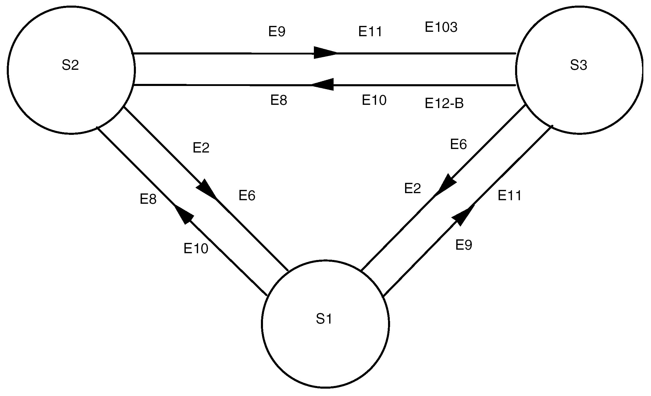 Figure 76: FOP-1 state transitions for main protocol
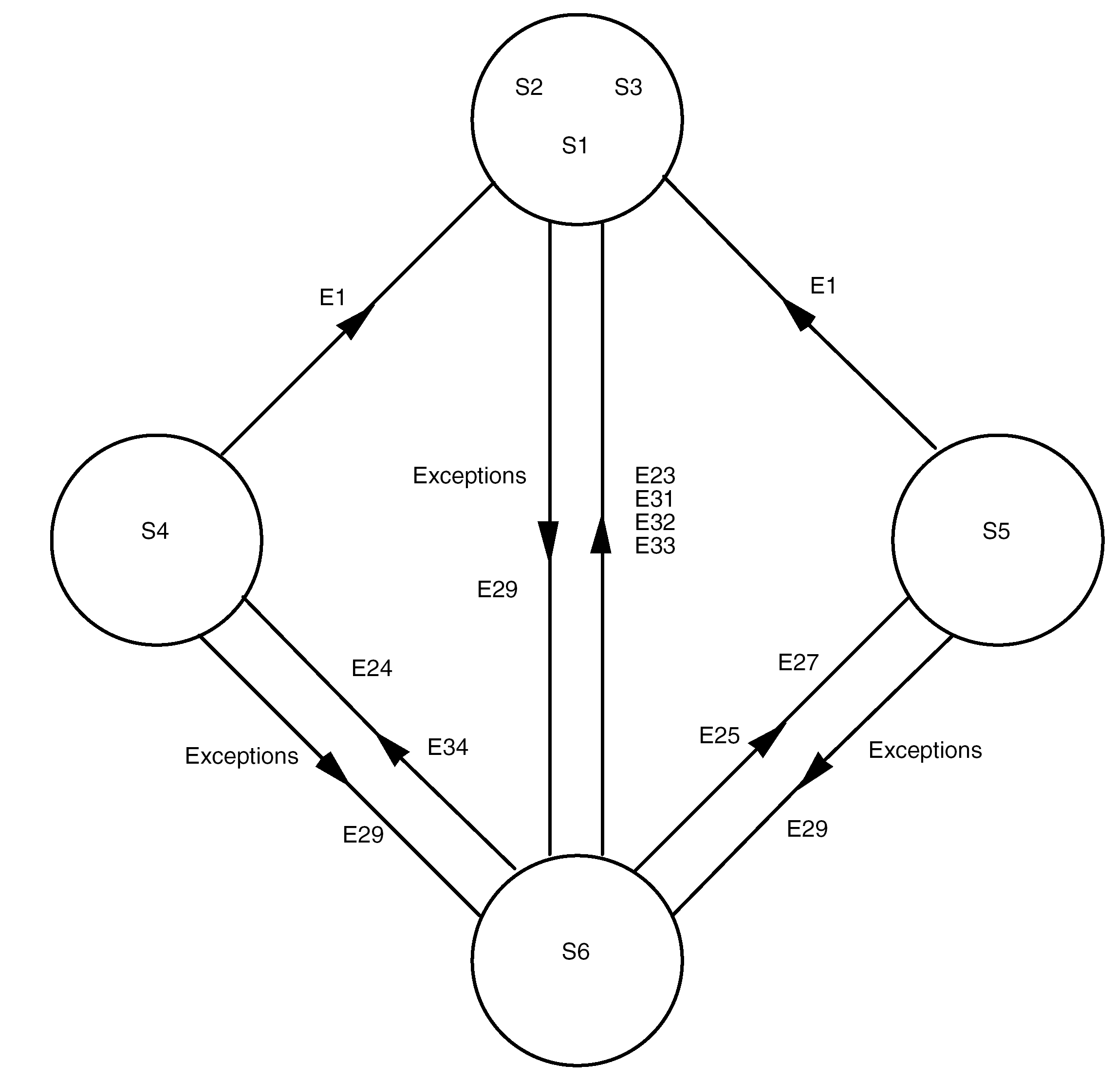 Figure 77: FOP-1 state transitions for initialisation protocol
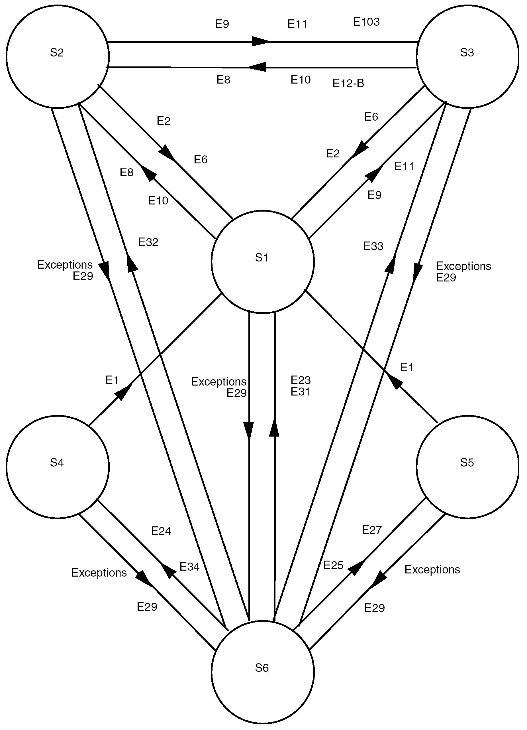 Figure 78: FOP-1 state transitions
Table 79: FARM-1 state table
|
|
|
State name
|
OPEN
|
WAIT
|
LOCKOUT
| |||
|
|
|
Mainfeature of state
|
Normal state to accept frames
|
Wait_Flag is on
|
Lockout_Flag is on
| |||
|
|
|
State Number
|
S1
|
S2
|
S3
| |||
|
Event conditions
|
EventNumber
|
|
|
|
||||
|
Validuserdatatype-AD framearrives
|
N(S)=V(R)
|
A buffer is available for this frame
|
E1
|
Accept frame,V(R):=V(R)+1,Retransmit_Flag:=0
|
Notapplicable
|
Discard
| ||
|
(S1)
|
|
(S3)
| ||||||
|
No buffer is available for this frame
|
E2
|
Discard,Retransmit_Flag:=1,Wait_Flag:=1
|
Discard
|
Discard
| ||||
|
(S2)
|
(S2)
|
(S3)
| ||||||
|
N(S) > V(R) andN(S) (V(R)+PW-1)i.e. inside positive part of sliding window and N(S) V(R)
|
E3
|
Discard,Retransmit_Flag:=1
|
Discard
|
Discard
| ||||
|
(S1)
|
(S2)
|
(S3)
| ||||||
|
N(S) < V(R) andN(S) (V(R)-NW)i.e. inside negative part of sliding window
|
E4
|
Discard
|
Discard
|
Discard
| ||||
|
(S1)
|
(S2)
|
(S3)
| ||||||
|
N(S) > (V(R)+PW-1) andN(S) < (V(R)-NW)i.e. outside of sliding window
|
E5
|
Discard,Lockout_Flag:=1
|
Discard,Lockout_Flag:=1
|
Discard
| ||||
|
(S3)
|
(S3)
|
(S3)
| ||||||
(Cont’d)
Table 79: FARM-1 state table (part 2)
|
|
|
State name
|
OPEN
|
WAIT
|
LOCKOUT
| |
|
|
|
State Number
|
S1
|
S2
|
S3
| |
|
Validusertype-BDframearrives
|
E6
|
Accept frame,Increment FARM-B_Counter
|
Accept frame,Increment FARM-B_Counter
|
Accept frame,Increment FARM-B_Counter
| ||
|
(S1)
|
(S2)
|
(S3)
| ||||
|
ValidUnlocktype-BCframearrives
|
E7
|
Increment FARM-B_Counter,Retransmit_Flag:=0
|
Increment FARM-B_Counter,Retransmit_Flag:=0,Wait_Flag:=0
|
Increment FARM-B_Counter,Retransmit_Flag:=0,Wait_Flag:=0,Lockout_Flag:=0
| ||
|
(S1)
|
(S1)
|
(S1)
| ||||
|
ValidSet V(R)type-BCframearrives
|
E8
|
Increment FARM-B_Counter,Retransmit_Flag:=0,V(R) := V*(R)
|
Increment FARM-B_Counter,Retransmit_Flag:=0,Wait_Flag:=0V(R) := V*(R)
|
Increment FARM-B_Counter
| ||
|
(S1)
|
(S1)
|
(S3)
| ||||
|
Invalidframearrives
|
E9
|
Discard
|
Discard
|
Discard
| ||
|
(S1)
|
(S2)
|
(S3)
| ||||
|
Bufferreleasesignal
|
E10
|
Ignore
|
Wait_Flag:=0
|
Wait_Flag:=0
| ||
|
(S1)
|
(S1)
|
(S3)
| ||||
|
CLCWreporttime
|
E11
|
Report value of V(R),Lockout_Flag,Wait_Flag,Retransmit_Flag,FARM-B_Counter
|
Report value of V(R),Lockout_Flag,Wait_Flag,Retransmit_Flag,FARM-B_Counter
|
Report value of V(R),Lockout_Flag,Wait_Flag,Retransmit_Flag,FARM-B_Counter
| ||
|
(S1)
|
(S2)
|
(S3)
| ||||
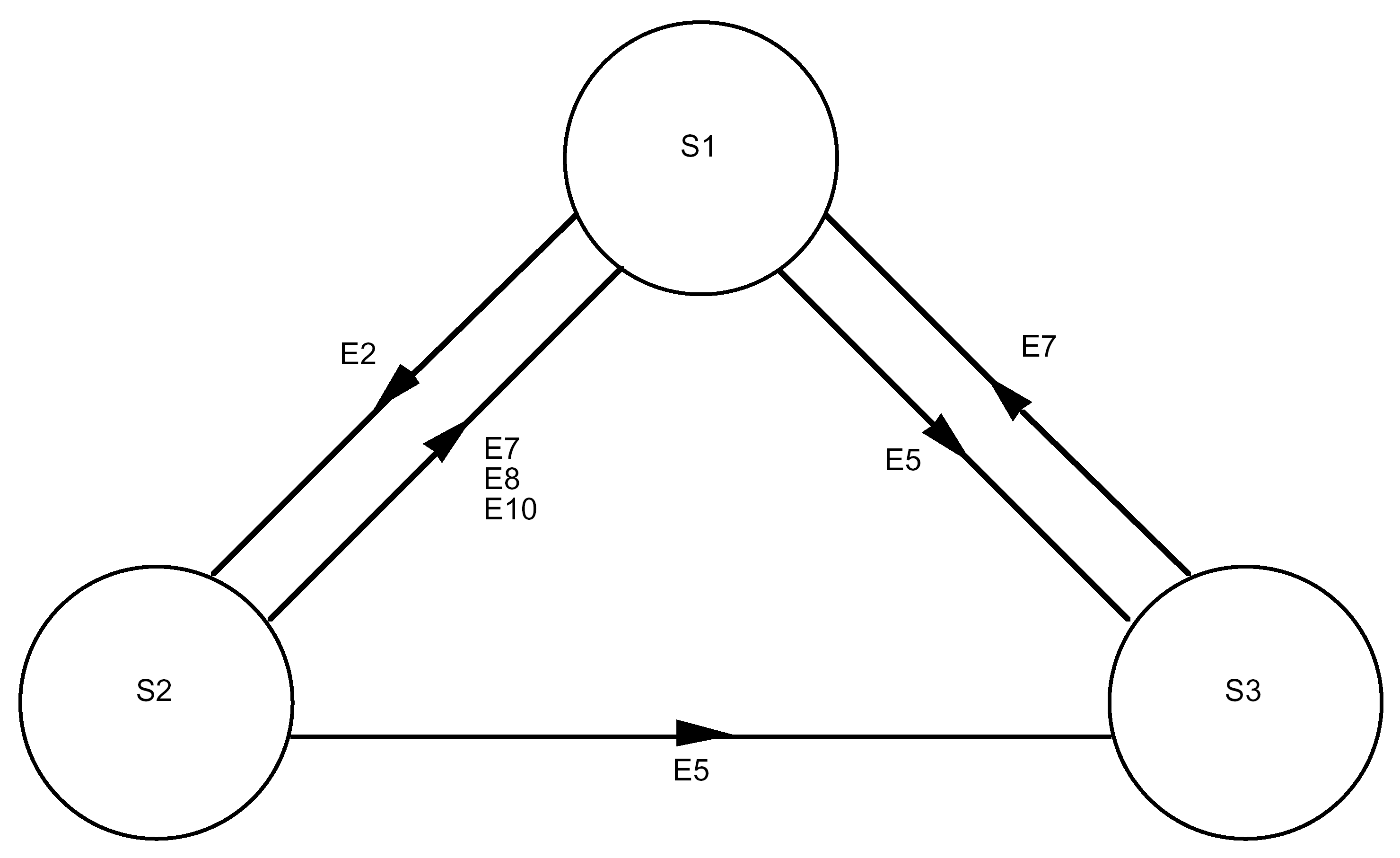 Figure 79: FARM-1 state transitions
Synchronization and channel coding sublayer
Overview
The synchronization and channel coding sublayer establishes an error-controlled data channel through which data can be transferred.
Annex D contains related performance data.
At the sending end, the data received by the synchronization and channel coding sublayer from the next higher sublayer are referred to as “input data”. The input data are encoded with a Bose-Chaudhuri-Hocquenghem (BCH) block code to reduce the effects on the data of noise in the physical channel.
The communications link transmission unit (CLTU) is the data structure that carries the input data from the synchronization and channel coding sublayer at the sending end to the same sublayer at the receiving end. The CLTU contains the input data as a contiguous series of encoded BCH codeblocks. The CLTU provides synchronization for the codeblocks and it delimits the beginning of the input data.
If the next higher sublayer is the transfer sublayer defined in Clause 6, then the input data consist of a TC Transfer Frame. In this case, a CLTU carries exactly one TC Transfer Frame.
The synchronization and channel coding sublayer also includes procedures for data randomizing.
The standard data structures within the sublayer are the BCH codeblock and the CLTU.
BCH codeblock
General
A BCH codeblock shall have a length of 8 octets (64 bits).
A BCH codeblock shall consist of two major fields, positioned contiguously, in the following sequence:
- Information 56 bits
- Error Control 8 bits
Both fields are always present. Figure 81 shows the format of a BCH codeblock.
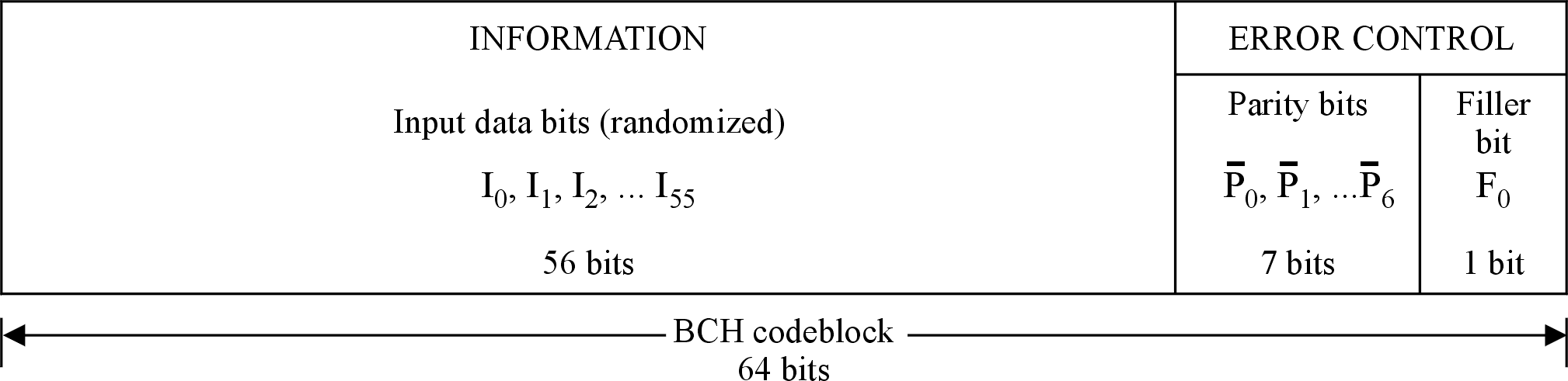 Figure 81: BCH codeblock format
Information
The Information field shall always be present in a BCH codeblock.
The Information field shall be contained in bits 0 to 55 of the BCH codeblock.
The Information field shall contain data bits from the input data, which shall be randomized as defined in clause 8.4.
The data can include fill bits as defined in clause 8.6.
Error Control
General
The Error Control field shall always be present in a BCH codeblock.
The Error Control field shall be contained in bits 56 to 63 of the BCH codeblock.
The Error Control field shall consist of two fields, positioned contiguously, in the following sequence:
- Parity bits 7 bits
- Filler bit 1 bit
Both fields are always present.
Parity bits
The Parity bits shall always be present in a BCH codeblock.
The Parity bits shall be contained in bits 56 to 62 of the BCH codeblock.
The Parity bits shall consist of the complements of the seven parity check bits, P0 through P6.
- 1 The encoding procedure for generating the parity bits is described in clause 8.4.4.
- 2 The complements are used to assist in maintaining bit synchronization and detection of bit slippage.
Filler Bit
The Filler bit, F0, shall always be present in a BCH codeblock.
The Filler bit shall be contained in bit 63 of the BCH codeblock.
The Filler bit shall always be set to zero.
The Filler bit provides an overall codeblock length that is an integer number of octets.
Communications link transmission unit (CLTU)
General
A CLTU shall consist of three major fields, positioned contiguously, in the following sequence:
- Start Sequence 16 bits
- Encoded Data variable length
- Tail Sequence� 64 bits
All three fields are always present. Figure 82 shows the format of a CLTU.
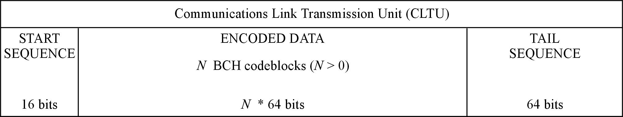 Figure 82: Format of a CLTU
Start Sequence
The Start Sequence field shall always be present in a CLTU.
The Start Sequence field shall be contained in bits 0 to 15 of the CLTU.
The Start Sequence field shall contain the bit pattern shown in Figure 83.
Expressed in hexadecimal, the bit pattern is EB90.
 Figure 83: Bit pattern of the Start Sequence
When searching for the Start Sequence in the bit stream at the receiving end, a bit sequence that matches the Start Sequence bit pattern with a one bit error shall be recognized as a Start Sequence.
- 1 The Start Sequence bit pattern has a high autocorrelation function following an idle or acquisition sequence. The Start Sequence:
- synchronizes the start of a CLTU;
- delimits the start of the first codeblock.
- 2 The Start Sequence of the CLTU is suitable for use to resolve ambiguity between true and complemented binary data (i.e. sense of ‘1’ and ‘0’) if this ambiguity is not resolved by other means (e.g. differential encoding) before CLTU processing.
Encoded Data
The Encoded Data field shall always be present in a CLTU.
The Encoded Data field shall start at bit 16 of the CLTU.
The Encoded Data field shall consist of an integral number of BCH codeblocks.
The Encoded Data field shall contain at least one BCH codeblock.
If the next higher sublayer above the synchronization and channel coding sublayer is the transfer sublayer defined in Clause 6, then the input data for the BCH codeblocks of a CLTU shall consist of a single TC Transfer Frame.
In this case, a CLTU carries exactly one TC Transfer Frame.
Tail Sequence
The Tail Sequence field shall always be present in a CLTU.
The Tail Sequence field shall
- Have a length of 8 octets.
- Be contained in the last 64 bits of the CLTU.
The first seven octets of the Tail Sequence field shall each contain the bit pattern 11000101 (hexadecimal C5).
The final octet of the Tail Sequence field shall contain the bit pattern 01111001 (hexadecimal 79). - 1 The total bit pattern for the Tail Sequence field is as follows:
11000101 11000101 11000101 11000101
11000101 11000101 11000101 01111001
- 2 The Tail Sequence field is constructed specifically to be a noncorrectable sequence which delimits the end of a CLTU by stopping the decoding process. The Tail Sequence field has the same length as a BCH codeblock.
Randomization procedure
Overview
Pseudo-randomization, referred to here as randomization, is a bandwidth-efficient technique of algorithmically translating the data bits to ensure frequent bit transitions in the communications channel. Bit (or symbol) synchronization with the received telecommand signal can only be maintained if the incoming signal provides a minimum bit transition density.
In randomization, a random sequence is exclusively ORed with the input data to increase the frequency of bit transitions. On the receiving end, the same random sequence is exclusively ORed with the decoded data, restoring the original data form. The random sequence is generated by the bit transition generator (BTG).
General
The randomizer defined here shall be used in all CLTUs passed to the physical layer.
Randomization shall be applied to the input data in a codeblock at the sending end before the encoding procedure for the codeblock is executed.
Random sequence
The random sequence shall be generated using the following polynomial:
h(x) = x8 + x6 + x4 + x3 + x2 + x + 1
This sequence repeats after 255 bits. The first 40 bits of the sequence are:
1111 1111 0011 1001 1001 1110 0101 1010 0110 1000
Increasing time-------------------------------------------->
The bit transition generator shall function according to the basic logical diagram in Figure 84.
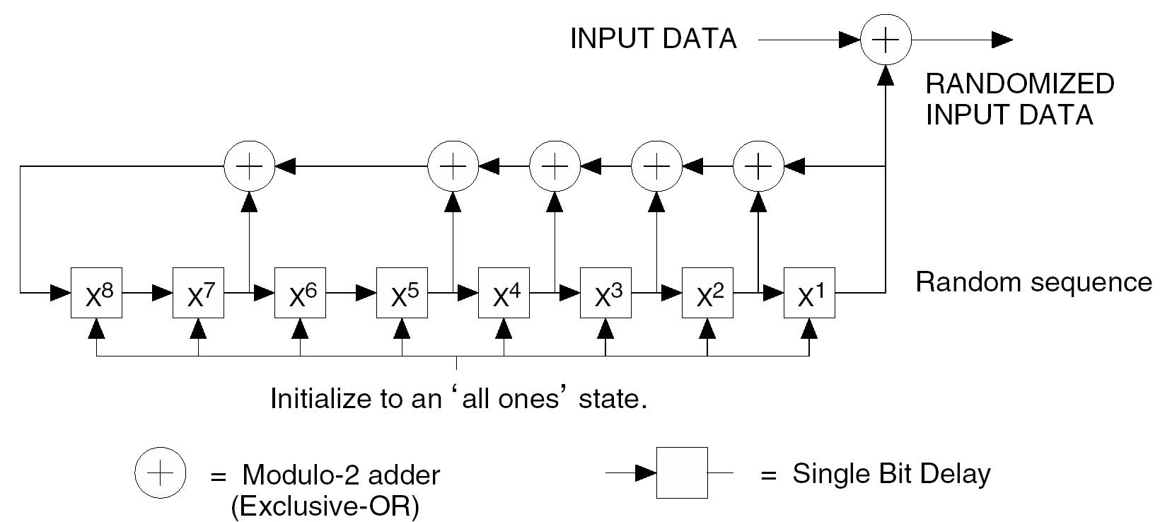 Figure 84: Bit transition generator logic diagram
Application of the randomizer
At the sending end, the randomization is applied to the input data. The BTG is preset to the "all-ones" state and then is exclusively ORed, bit by bit, with the input data until the end of the input data is reached.
The randomization can also be applied to the fill bits added after the end of the input data to complete the last codeblock of the CLTU.
The randomization is not applied to the Error Control field at the end of each BCH codeblock.
At the receiving end, the derandomization is applied to the successfully decoded data. The BTG remains in the "all-ones" state until the CLTU Start Sequence has been detected. The BTG pattern is exclusively ORed, bit by bit, to the successfully decoded data (after the Error Control bits have been removed) from each BCH codeblock.
The BTG is reset to the "all-ones" state following a failure of the decoder to successfully decode a BCH codeblock or if the telecommand channel becomes inactive.
At the receiving end, INPUT DATA in Figure 84 represents the successfully decoded data from a CLTU and RANDOMIZED INPUT DATA represents the restored original data that is output by the randomizer.
BCH codeblock encoding procedure
A systematic block coding procedure is used which always generates 7 parity check bits per codeblock and which is always computed from 56 information bits. The parity check bits are then complemented and placed into the codeblock as shown in Figure 81.
The code used is a (63,56) modified Bose-Chaudhuri-Hocquenghem (BCH) code which uses the following generator polynomial to produce the seven parity bits:
g(x) = x7 + x6 + x2 + 1
The code generator implementation is illustrated in Figure 85. Note that the shift registers are initialized to zero. The ganged switch is in:
Position 1 while the 56 telecommand data bits are being transmitted.
Position 2 for the seven parity bits.
Position 3 for the appended filler bit.
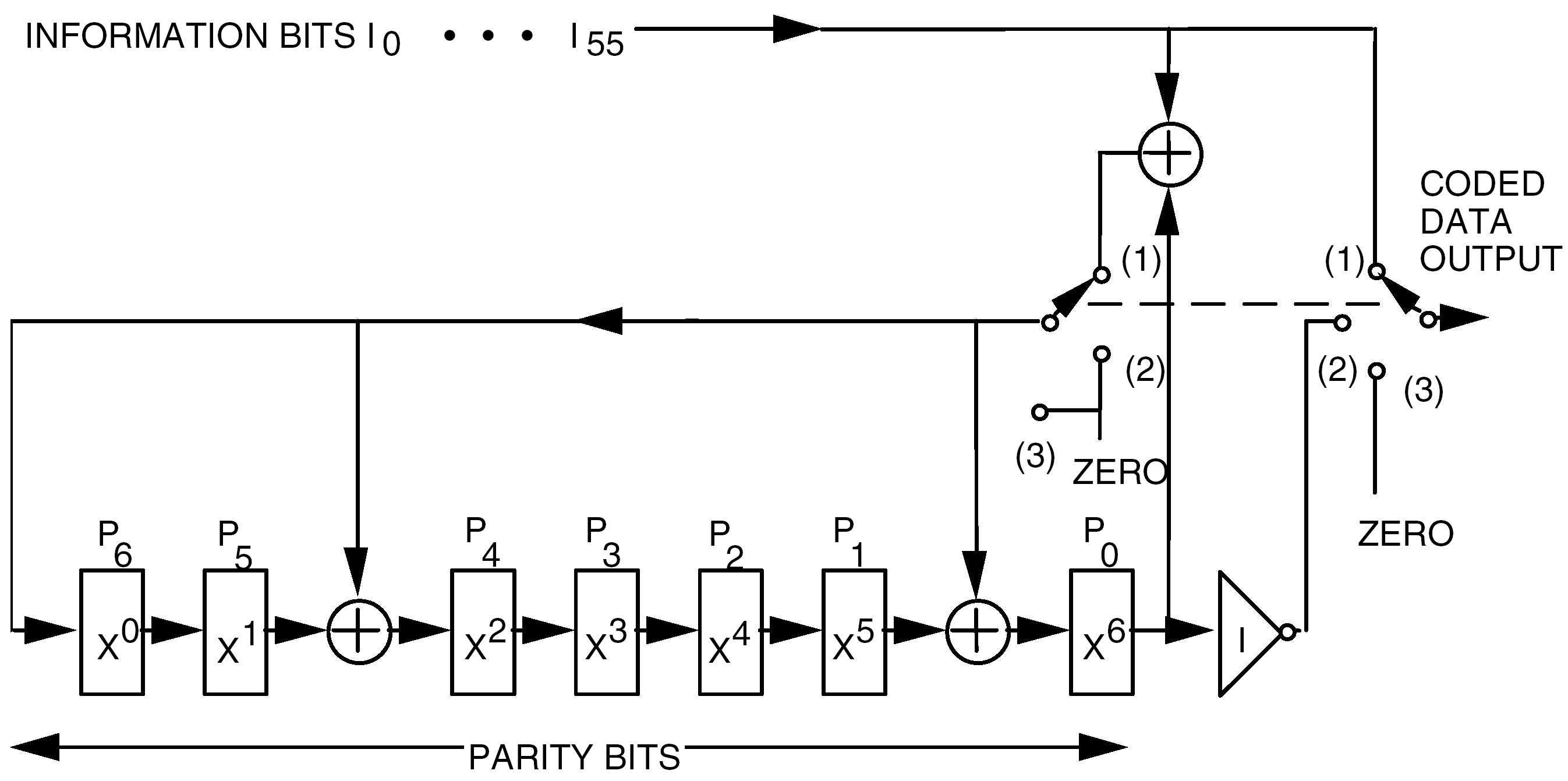 Figure 85: (63,56) Modified BCH code generator
Fill bits
Overview
If the input data does not fit exactly in an integral number of BCH codeblocks then fill bits are added to the last codeblock in a CLTU.
General
If a CLTU contains fill bits, then the fill bits shall be present only in the last BCH codeblock within a CLTU.
If a BCH codeblock contains fill bits, the fill bits shall be in the last octets of the Information field of the codeblock.
If a BCH codeblock contains fill bits, the length of the fill bits shall be an integral number of octets.
The pattern of the fill shall consist of a sequence of alternating "ones" and "zeroes" starting with a "zero".
- 1 The synchronization and channel coding sublayer can introduce fill bits at the sending end but they are not removed by the synchronization and channel coding sublayer at the receiving end. The transfer sublayer defined in Clause 6 includes the frame delimiting and fill removal procedure, which is responsible for the removal of fill bits from candidate frames received from the synchronization and channel coding sublayer.
- 2 Any fill octets added to the last codeblock of the CLTU are derandomized even if they are not randomized.
Channel logic at the receiving end
The logic for the channel at the receiving end of the synchronization and channel coding sublayer is presented as a state diagram in Figure 86. To support the state diagrams, a list of states and events is given in Table 81 and Table 82. There are three states and four events.
In state S3, if the number of codeblocks received exceeds an upper limit, then the CLTU is abandoned and state S2 is entered. The value for the upper limit for the number of codeblocks is implementation dependent.
If the channel is active in state S3 but no data are received due to loss of symbol clock, then the CLTU is abandoned and state S1 is entered.
Table 81: Channel states (receiving end)
|
State Number
|
State Name
|
State Definition
|
|
S1
|
Inactive
|
The telecommand channel is inactive, i.e.
|
|
S2
|
Search
|
The incoming bit stream is searched, bit by bit, for the Start Sequence pattern.
|
|
S3
|
Decode
|
BCH codeblocks, which are either free of error or that can be corrected, are received and decoded, and their contents are derandomized and transferred to the next higher sublayer.
|
Table 82: Channel events (receiving end)
|
Event Number
|
Event Name
|
Event Definition
|
|
E1
|
Channel activation
|
Bit modulation is detected and bit lock is achieved: telecommand bit stream is present.
|
|
E2
|
Channel deactivation
|
Bit lock is lost or telecommand signal is lost: telecommand bit stream is not present.
|
|
E3
|
Start sequence found
|
The Start Sequence pattern has been detected, signalling the beginning of the first codeblock of the CLTU.
|
|
E4
|
Codeblock rejection
|
The decoder has indicated uncorrected errors in a codeblock. No data from this codeblock is transferred to the next higher sublayer.
|
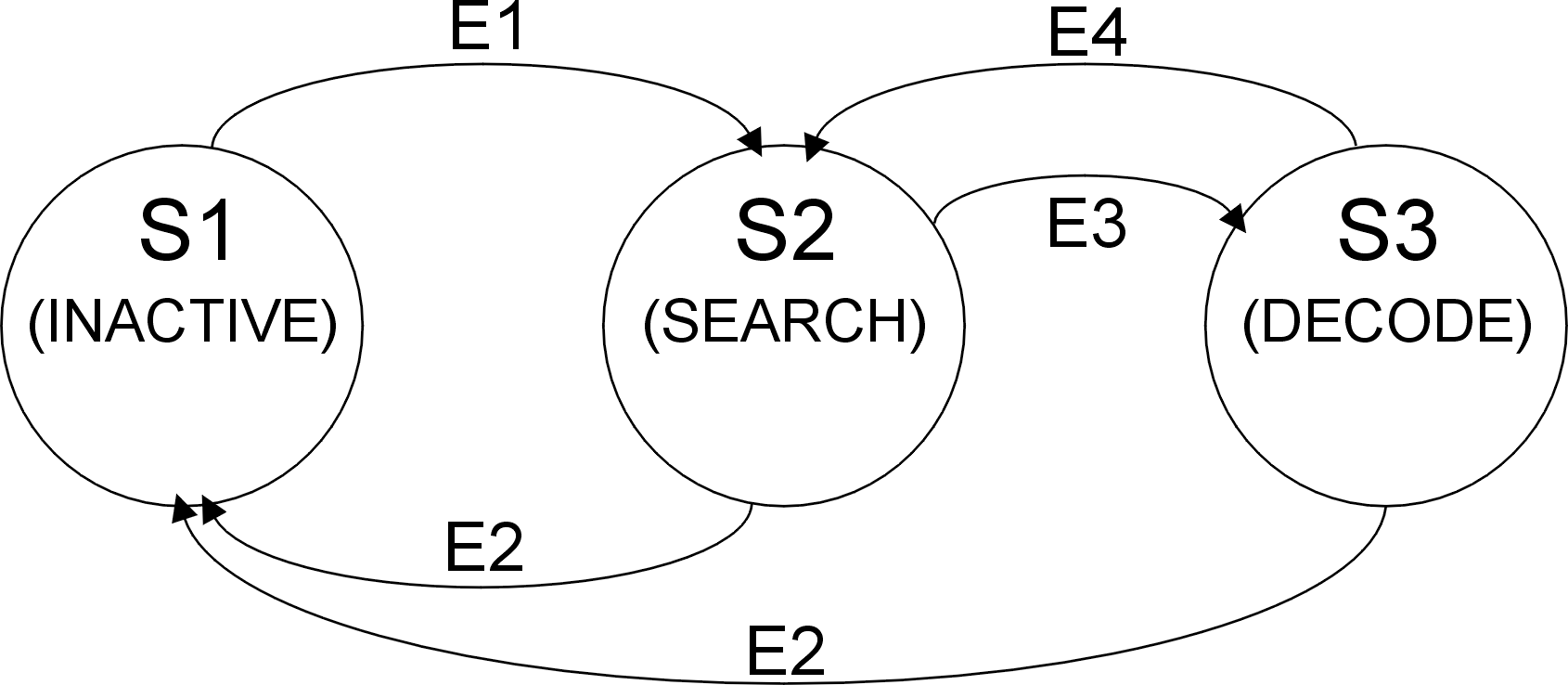 Figure 86: State diagram for the channel (receiving end)
BCH codeblock decoding procedures
Overview
Codeblocks that are encoded using the modified BCH code described in clause 8.4.4 are decoded in an error-correcting mode. One bit in error is corrected and two bits in error are detected. This mode is therefore also known as single-error correction (SEC).
The modified BCH code described in clause 8.4.4 also supports an error-detecting mode. In this case, one, two or three bits in error are detected within the codeblock (not counting the appended Filler bit) and the mode is therefore also known as triple-error detection (TED). This Standard does not specify the use of the error-detecting mode.
General
Codeblocks shall be decoded in error-correcting mode.
- 1 The Frame Error Control Field specified in clause 6.2.4 enables the detection of frames that have residual errors after the codeblocks are decoded in error-correcting mode.
- 2 This description of decoding assumes that the physical layer produces a hard decision output, so that the synchronization and channel coding sublayer receives a sequence of elements that are either ‘0’ or ‘1’. However, a physical layer which produces a soft decision output with more quantization levels is not excluded.
Physical layer
Overview
The physical layer provides the radio frequency data path and its associated physical layer operation procedure (PLOP). This clause is limited to the procedure aspects of the physical layer, including the related data structures. The radio frequency and modulation aspects of the physical layer are addressed in ECSS-E-ST-50-05.
The standard data structures within the layer are
the acquisition sequence,
the CLTU and
the idle sequence.
They are used to provide synchronization of the symbol stream.
Physical layer data structures
Acquisition sequence
The length of the acquisition sequence shall be at least 128 bits.
The pattern of the acquisition sequence shall be alternating "ones" and "zeroes", starting with either a "one" or a "zero".
- 1 The acquisition sequence is a data structure forming a preamble which provides for initial symbol synchronization within the incoming stream of detected symbols.
- 2 The length of the acquisition sequence is selected according to the mission telecommand link performance specifications.
- 3 The length of the acquisition sequence can be effectively increased by transmitting the idle sequence defined in clause 9.2.3.
CLTU
The CLTU as delivered to the physical layer shall be randomized as described in clause 8.4.
- 1 The CLTU is the data structure (symbol sequence) furnished from the next higher sublayer, and defined in clause 8.3. It contains the data symbols to be transmitted to the receiving end.
- 2 Each codeblock within the CLTU, that has the format specified in clause 8.2, provides at least two data transitions. Randomization is used to guarantee sufficiently frequent transitions for adequate symbol synchronization.
Idle sequence
The length of the idle sequence shall be at least 8 bits.
The maximum length of the idle sequence is an unconstrained number of bits.
The pattern of the idle sequence shall be alternating "ones" and "zeroes", starting with either a "one" or a "zero".
- 1 The idle sequence is the data structure that provides for maintenance of symbol synchronization in the absence of CLTUs.
- 2 Because of the improved performance of the tail sequence defined in clause 8.3.4, the idle sequence is not constrained to begin with a zero.
Physical layer procedures
Overview
Operations within the physical layer begin with the activation of the physical telecommand channel by invoking the radio frequency carrier and modulation techniques. These techniques include any command link subcarriers and data modulation provided in order to establish the physical connection from the transmitting end to the proper hardware at the receiving end.
Carrier modulation modes
Overview
Carrier modulation modes (CMMs) consist of different states of data modulation upon the RF carrier that creates the physical telecommand channel. The physical methods of modulating the carrier, which can be either spread spectrum or subcarrier techniques, are described in ECSS-E-ST-50-05. The carrier modulation modes are shown in Table 91.
Table 91: Carrier modulation modes
|
Mode
|
State
|
|
CMM-1
|
Unmodulated carrier only
|
|
CMM-2
|
Carrier modulated with acquisition sequence
|
|
CMM-3
|
Carrier modulated with telecommand data (e.g. CLTU)
|
|
CMM-4
|
Carrier modulated with idle sequence
|
|
NOTE: Unmodulated is defined as the state in which no telecommand modulation is present.
| |
CMM-1
Mode CMM-1 is concerned with the establishment of the radio-frequency part of the physical connection, as specified in ECSS-E-ST-50-05.
In operating the acquisition procedures, the sending end uses information on the lock status of the receiving spacecraft transponders. The information is carried by the No RF Available Flag in the communications link control word (CLCW) as specified in clause 6.3.8.
CMM-2
Mode CMM-2 is concerned with the establishment of the modulation part of the physical connection.
The sending end transmits an acquisition sequence with a minimum length of 128 bits, as defined in clause 9.2.1. The sending end uses information on the quality of the received bit stream. The information is carried by the No Bit Lock Flag in the CLCW as specified in clause 6.3.9. The flag provides the same service throughout CMM-3 and CMM-4.
CMM-3
Mode CMM-3 is concerned with the transmission of one CLTU on the physical connection.
CMM-4
Mode CMM-4 is concerned with the maintenance of the modulation part of the physical connection.
An idle sequence of at least 8 bits is transmitted between each CLTU and the next. The maximum length of the idle sequence is unconstrained and is dictated by the timing of the telecommand operations (e.g. when no CLTU is available).
Telecommand session
During a telecommand session, a series of CLTUs is transmitted to a remote spacecraft. The session begins with the initial application of the RF carrier (CMM-1) and ends with the removal of the carrier. The path is further controlled (activated or deactivated) by the physical layer operation procedure (PLOP).
Physical layer operation procedure (PLOP)
Overview
The PLOP consists of a sequential application of the various CMMs in order to activate and deactivate the physical telecommand channel. Two procedures, PLOP-2 and PLOP-1, are defined.
General
PLOP-2 should be used in preference to PLOP-1.
PLOP-2 supports a higher data throughput on the physical telecommand channel. PLOP-1 is included here for completeness and is used, for example, by ground systems and for cross support.
PLOP-2
PLOP-2 is a procedure whereby the physical telecommand channel is not deactivated after each transmitted CLTU. The termination of an individual CLTU is provided only through the data path, using the CLTU Tail Sequence and an idle sequence. This places the decoder in the search state (S2, defined in Table 81) after each CLTU. The decoder is forced into the inactive state (S1), by deactivating the physical telecommand channel only at the end of transmission of a series of CLTUs.
PLOP-2 invokes the sequence of CMMs shown in Figure 91.
When operating with PLOP-2, a minimum idle sequence of one octet is inserted between each CLTU to eliminate the small but finite risk of synchronization lockout. Such a lockout can occur if the start pattern of one CLTU is not detected (leaving the decoder in search state) and a start pattern exists over the last bits of the last codeblock of that CLTU and the first bits of its Tail Sequence. This creates an erroneous but temporary CLTU start (decode state), causing the true start of the following CLTU to be missed. The added idle sequence prevents this from happening.
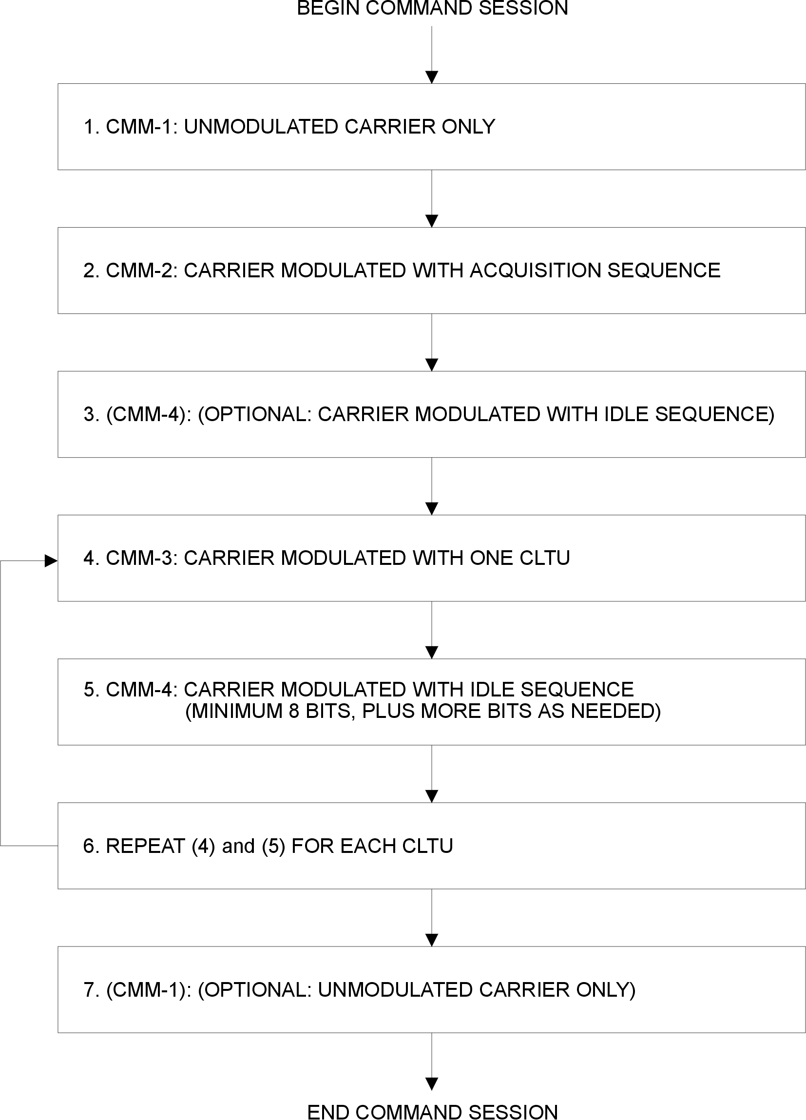 Figure 91: Sequence of CMMs comprising PLOP-2
PLOP-1
PLOP-1 is a procedure for individually radiating CLTUs, whereby the physical communications channel is deactivated after the end of transmission of each CLTU (or CLTU followed by an Idle Sequence). As a result, the decoder is forced into the inactive state (S1, defined in Table 81) after each CLTU,
PLOP-1 invokes the sequence of CMMs shown in Figure 92.
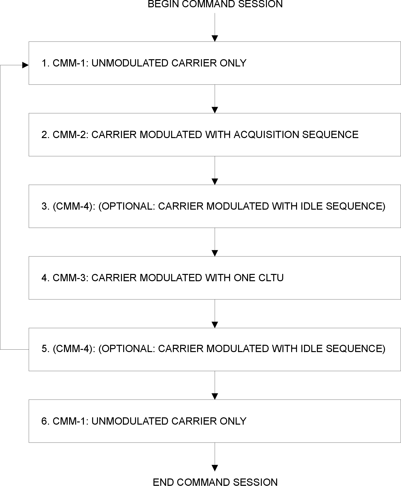 Figure 92: Sequence of CMMs comprising PLOP-1
ANNEX(informative)Frame error control
Overview
This annex describes example implementations of the encoding and decoding procedures for the cyclic redundancy code used for the Frame Error Control Field defined in clause 6.2.4.
The bit numbering convention specified in clause 3.4.1 applies in this annex.
Encoding
Figure A-1shows an arrangement for an encoder to generate the Frame Error Control Field value, FECF, as given in the equation in clause 6.2.4.2. For the 16-bit FECF value, the first bit transferred is the most significant bit P0 taken as the coefficient of the highest power of X.
The encoder uses a shift register and each small rectangle in the figure represents a bit in the shift register. For each frame, the shift register bits are initialized to “one” before the encoding.
For encoding, the position of the ganged switch is as follows:
1 when the (n16) information bits are being transferred;
2 when the encoder outputs the 16 bits of FECF.
 Figure: Encoder
Decoding
Figure A-2 shows an arrangement for a decoder to generate the syndrome polynomial, S(X), as given in the equation in clause 6.2.4.3.
The decoder uses a shift register and each small rectangle in the figure represents a bit in the shift register. For each frame, the shift register bits are initialized to “one” before the decoding.
The frame contains n bits, which consist of the (n-16) information message bits followed by the 16 bits, FECF, of the Frame Error Control Field.
To decode:
All the n bits of the frame are clocked into the input.
The contents of the shift register are then examined. For an error-free frame, all bits in the shift register are zero. A non-zero content indicates an erroneous frame.
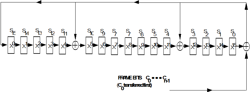 Figure: Decoder
ANNEX(informative)Changes from ESAPSS-04-107
Overview
This annex describes some of the technical differences between this Standard and ESAPSS-04-107, ESA Packet telecommand standard, Issue 2, April 1992.
The main purpose of the annex is to assist in checking compatibility of existing systems.
The list of differences in this annex provides an indication of some of the differences of technical content between this Standard and ESAPSS-04-107. However, it is not the purpose of this annex to provide a complete list nor to provide full details on each item in the list nor to describe the consequences of each item in the list. Refer to the contents of this Standard and to the PSS documents for further details.
ESAPSS-04-107 has a wider scope than this Standard. This annex only includes differences that are within the scope of this Standard.
Technical changes
The names of some of the layers have been changed. For example, the name “Segmentation Layer” in ESAPSS-04-107 is changed to “segmentation sublayer” in this Standard.
Segmentation sublayer:
This Standard includes a blocking function for packets so that multiple packets can be carried in a frame.
ESAPSS-04-107 does not include the function.
Segmentation sublayer:
In this Standard, there can be virtual channels which do not use TC Segments and, as a result, there can be frames which do not contain a Segment Header in the Transfer Frame Data Field.
In ESAPSS-04-107, TC Segments are used for all virtual channels.
Segmentation sublayer:
ESAPSS-04-107 assumes that the layer below the Segmentation Layer is the Transfer Layer.
This Standard makes some assumptions about the layer or sublayer below but does not assume that it is any specific layer or sublayer.
Segmentation sublayer:
ESAPSS-04-107 defines telecommand authentication. This is outside the scope of this Standard.
Also, ESAPSS-04-107 defines an optional Segment Trailer field in a TC Segment to accommodate the authentication data. The definition of the TC Segment in this Standard does not include the Segment Trailer.
Transfer sublayer:
In this Standard the maximum length of a TC Transfer Frame is 1024 octets.
In ESAPSS-04-107 the maximum length is 256 octets. Correspondingly, in this Standard the Frame Length field occupies bits 22-31; in ESAPSS-04-107 it occupies bits 24-31 (and bits 22-23 are reserved).
COP-1:
This Standard specifies a modified version of COP-1, known as COP-1B.
ESAPSS-04-107 specifies an older version which is now known as COP1A.
The differences only affect the sending end (FOP-1) not the receiving end (FARM-1).
COP-1:
In this Standard, the Status Field (bits 3-5) of a CLCW can be used for mission-specific purposes.
In ESAPSS-04-107, the field is always set to zero.
COP-1:
Efficient operation of COP-1 can only be achieved if some minimum CLCW sampling rate is provided via telemetry.
ESAPSS-04-107 specifies two methods to achieve this: Standard Insertion Scheme 1 and 2.
In this Standard, the sampling rates and the associated methods are project specific and they are not specified.
Synchronization and channel coding sublayer:
The bit pattern in the Tail Sequence of a CLTU is different.
Synchronization and channel coding sublayer:
This Standard includes randomization, which is not in ESAPSS-04-107.
Synchronization and channel coding sublayer:
This Standard uses the name BCH codeblock for the structure called a TC codeblock in ESAPSS04107.
Synchronization and channel coding sublayer:
This Standard only defines BCH codeblocks with a length of 64 bits.
ESAPSS-04-107 also defines lengths of 56, 48 and 40 bits.
Physical layer:
In ESAPSS-04-107, the acquisition sequence ends with “one” when followed by idle.
This Standard does not specify a value in this case.
Physical layer:
In ESAPSS-04-107 the idle sequence starts with “zero”.
In this Standard it may start with “zero” or “one”.
Physical layer:
This standard defines PLOP-1 and PLOP_2.
ESAPSS-04-107 only defines PLOP-2.
The differences in the names of fields in a TC Transfer Frame and in a CLCW, as shown in Table B-1.
In this Standard the word “Communications” is used rather than “Command” in forming names, as shown in Table B-2.
Table: Field name differences from ESAPSS-04-107
|
Datastructure
|
Name in ESAPSS-04-107
|
Name in this Standard
|
|
TC Transfer Frame
|
Frame Header
|
Transfer Frame Primary Header
|
|
Version Number
|
Transfer Frame Version Number
| |
|
Reserved Field A
|
Reserved Spare
| |
|
Reserved Field B
|
(part of Frame Length)
| |
|
Frame Data Field
|
Transfer Frame Data Field
| |
|
CLCW
|
Virtual Channel Identifier
|
Virtual Channel Identification
|
|
Reserved Field
|
Reserved Spare
| |
|
Report Type
|
Reserved Spare
|
Table: Names with “Communications” or “Command”
|
Name in this Standard
|
Abbreviation
|
Name in ESAPSS-04-107
|
|
Communications Operation Procedure-1
|
COP-1
|
Command Operation Procedure-1
|
|
Communications Link Control Word
|
CLCW
|
Command Link Control Word
|
|
Communications Link Transmission Unit
|
CLTU
|
Command Link Transmission Unit
|
ANNEX(informative)Differences from CCSDS recommendations
Overview
This annex describes the technical differences between this Standard and the related CCSDS recommendations:
CCSDS 231.0B1
CCSDS 232.0B1
CCSDS 232.1B1.
Many of the differences consist of additional options that are available in the CCSDS recommendations. These differences can be significant for systems, especially for ground segments, that provide cross-support for CCSDS-compatible missions.
This annex lists the differences of technical content between this Standard and the CCSDS recommendations indicated. However, it is not the purpose of this annex to provide complete details on each item in the list or to describe the consequences of each item in the list. Refer to the contents of this Standard and to the CCSDS recommendations for further details.
The CCSDS recommendations mentioned in C.1 have a wider scope than this Standard. This annex only includes the differences that are within the scope of this Standard.
Differences
The CCSDS recommendations assume that the sublayer below the segmentation sublayer is the transfer sublayer.
This Standard makes some assumptions about the sublayer below but does not assume that it is the transfer sublayer.
The CCSDS recommendations similarly assume that the next higher sublayer to the transfer sublayer is the segmentation sublayer.
This Standard includes the optional Packet Assembly Controller in the segmentation sublayer.
The CCSDS recommendations do not include the Packet Assembly Controller.
As a result, the minimum length of a TC Segment in this Standard is one octet and in the CCSDS recommendations the minimum length of a segment is two octets.
In the CCSDS recommendations, multiple Transfer Frames can be put in a single CLTU (see section 4.2.1 of CCSDS 231.0B1).
In this Standard, a CLTU contains exactly one frame.
In this Standard, all TC Transfer Frames include the Frame Error Control Field.
In the CCSDS recommendations this field is optional.
As a result, the minimum length of a TC Transfer Frame in this Standard is eight octets and in the CCSDS recommendations the minimum length of a TC Transfer Frame is six octets.
In this Standard, the receiving-end channel always accepts a CLTU Start Sequence with a one-bit error.
In the CCSDS recommendations this behaviour is optional (see the note following Table 4-2 in CCSDS 231.0B1).
In this Standard, the randomization in the synchronization and channel coding sublayer is always used.
In the CCSDS recommendations randomization is optional.
In this Standard, the codeblocks of a CLTU are always decoded in the error-correcting mode, known as single error correction (SEC).
In the CCSDS recommendations, the codeblocks can also be decoded in the error-detecting mode, known as triple error detection (TED).
In PLOP-2 in this Standard, the idle sequence between CLTUs is always used.
In PLOP-2 in the CCSDS recommendations, the idle sequence between CLTUs is optional (see Figure 6-2 of CCSDS 231.0B1).
In this Standard, the acquisition sequence always has a length of at least 128 bits.
The CCSDS recommendations have a preferred minimum length of 128 bits for the acquisition sequence.
In this Standard, the idle sequence always has a length of at least 8 bits.
The CCSDS recommendations have no minimum length for the idle sequence.
In the CCSDS recommendations, the use of the No Bit Lock Flag in a CLCW is optional and mission-specific.
In this Standard, the use of the flag is defined and it is always used.
In the CCSDS recommendations, some names of data structures and other entities are different. Some of the differences are shown in Table C-1.
Table: Name differences from CCSDS recommendations
|
Name in restructured CCSDS recommendations
|
Name in this Standard
|
|
Segment
|
TC Segment
|
|
Service Data Unit
|
user data unit
|
|
User Data
|
Segment Data Field
|
In this Standard, an FDU arrived indication from FARM-1 always has a parameter for the FDU aborted indication.
In CCSDS 232.1B1, this parameter is optional.
This Standard includes procedures for the behaviour of a FARM-1 implementation which provides only one back-end buffer for a virtual channel.
CCSDS 232.1B1 does not consider this special case.
ANNEX(informative)Performance issues
Introduction
One of the objectives of the procedures and data structures defined in this Standard is to provide reliable delivery of TC Transfer Frames.
The performance criteria for reliable delivery of TC Transfer Frames are measured in terms of:
Frame rejection rate, where a frame is lost or deleted because of errors on the channel;
Frame undetected error rate, where a frame containing one or more undetected bit errors is erroneously accepted.
This annex provides performance data on the procedures in the Standard, to enable system engineers to design the system so that the performance criteria are satisfied.
Throughout this annex, it is assumed that the physical layer operation procedure PLOP-2 is used. See CCSDS 230.1-G-1 for performance information in cases when PLOP-1 is used.
Throughout this annex, a binary symmetric channel with additive white Gaussian noise is assumed.
Performance statistics are shown for three different channel bit error rates: 104, 105 and 106.
In equations, the channel bit error rate is represented by the letter p.
For further performance data and background information on the issues covered in this annex, see CCSDS 230.1-G-1.
The validity of some of the performance data in this annex relies on the assumption that TC Transfer Frames are processed as defined in this Standard. If sublayers are added, such as a security sublayer between the transfer sublayer and the synchronization and channel coding sublayer, then the error detection and correction performance can change.
Performance components
To support the performance criteria, this Standard specifies the following procedures for handling the TC Transfer Frame and related structures:
PLOP-2 and the acquisition sequence to enable the receiving end to acquire bit synchronization.
Randomization to ensure that the receiving end can maintain bit synchronization.
Placing a Start Sequence at the start of each CLTU so that the CLTU reception procedure can delimit the beginning of the first BCH Codeblock (and therefore the beginning of the frame) in the CLTU.
BCH encoding/decoding of the codeblocks to provide error detection and correction;
Placing a Tail Sequence at the end of each CLTU so that the CLTU reception procedure can detect the end of the CLTU and thus start searching for the Start Sequence of the next CLTU.
A frame delimiting and fill removal procedure to delimit the end of the TC Transfer Frame in the data extracted from the CLTU.
A frame error control procedure to check the Frame Error Control Field, which provides additional protection against undetected errors.
A frame header validation procedure to check the fields in the header of each TC Transfer Frame.
Factors affecting frame rejection rate
Bit synchronization factor
The PLOP in the physical layer at the sending end transmits CMM-1 (unmodulated carrier mode) at the start of a communications session. The transponder in the physical layer at the receiving end locks onto the signal.
Then the PLOP transmits the acquisition sequence (CMM-2) with the length selected for the mission. The acquisition sequence, consisting of alternating 1 and 0 bits, has maximum transition density, to provide the fastest lock-up time for the on-board bit synchronizer.
The minimum length of 128 bits for the acquisition sequence is chosen to provide 0,9999 probability of acquisition of bit synchronization. The length can be increased to suit different hardware characteristics or channel bit error rates.
The choice of the minimum length is based on experience with a number of hardware implementations operating in conditions where the frame rejection rate was near 10-3.
Because the probability of achieving bit synchronization is primarily hardware dependent, it is not considered further in the performance analysis in this annex. The remainder of this annex assumes that bit synchronization is achieved whenever the acquisition sequence is transmitted.
CLTU Start Sequence factors
Overview
There are two CLTU Start Sequence factors:
The probability that the CLTU reception procedure misses a Start Sequence because it is not in SEARCH state (S2) when the Start Sequence is received.
The probability that the Start Sequence is not recognized by the CLTU reception procedure in SEARCH state (S2).
CLTU reception procedure not in SEARCH state
If the Start Sequence follows an acquisition sequence (plus an optional length of idle sequence), then the SEARCH state of the CLTU reception procedure depends on successfully achieving bit synchronization. As described in D.3.1, this performance analysis assumes that bit synchronization is achieved.
Otherwise, the Start Sequence follows the Tail Sequence of the previous CLTU, with a minimum of one octet of idle sequence between the Tail Sequence and the Start Sequence.
The idle sequence protects against the synchronization lockout described in clause 9.3.4.3. The probability that the CLTU reception procedure is not in SEARCH state when receiving the Start Sequence therefore depends on the probability of failing to recognize the Tail Sequence – see D.3.4.
There is a remote possibility that the proper Start Sequence is missed because of a false (premature) start when the Start Sequence is erroneously recognized in the acquisition sequence / idle sequence pattern. The Start Sequence has a distance of 6 bits from the acquisition sequence / idle sequence, so it would take 6 changed bits to convert a section of the acquisition sequence / idle sequence into a Start Sequence. A Start Sequence with one error is accepted, so a change of 5 bits can be enough to cause a premature start.
Start Sequence not recognized
The Start Sequence is a 16-bit synchronization pattern. The CLTU reception procedure in SEARCH state examines the received stream of bits, looking for the Start Sequence pattern.
The Start Sequence is accepted with a single error. This means that the received bit pattern is accepted as a valid Start Sequence if it exactly matches the expected bit pattern or if it differs by one bit from the expected bit pattern. In this case, the probability PSY of failing to recognize the Start Sequence is therefore the probability that two or more bit errors appear in the 16 bits of the Start Sequence:
Equation PSY = 1 - [(1-p)16+16p(1-p)15] D1
Table D-1 shows the values of the probability PSY for the three channel bit error rates.
Table: Probability of not recognizing the Start Sequence
|
BER
|
10–4
|
10–5
|
10–6
|
|
PSY
|
1,20 × 10⁻⁶
|
1,20 × 10⁻⁸
|
1,20 × 10⁻¹⁰
|
BCH Codeblock Factor
Codeblock rejection in SEC Mode for a single codeblock
Two of the values used in the decoding process are the error parity check, PAR, and the syndrome, SYND, shown in Table D-2. In SEC mode, the values are used to determine the actions of the decoder, and they lead to six possible cases, as shown in. Table D-3
Table: Meaning of decoding values
|
Error parity check
|
PAR=0
|
The number of errors is even, 0, 2, 4, 6, …
|
|
PAR=1
|
The number of errors is odd, 1, 3, 5, 7, …
| |
|
Syndrome
|
SYND=0
|
The received codeword is a valid codeword, though not necessarily the one that was transmitted
|
|
SYND>0
|
The received codeword is not valid, so errors are present
|
Table: Decoding cases in SEC mode
|
PAR
|
SYND
|
Action
|
Case
| |
|
0
|
0
|
Accept codeblock
|
A1
|
The received codeblock has no errors
|
|
A2
|
The received codeblock has an even number of errors (at least 4)
| |||
|
0
|
>0
|
Codeblockrejection
|
B
|
The received codeblock has an even number of errors (at least 2)
|
|
1
|
0
|
Codeblockrejection
|
C
|
The received codeblock has an odd number of errors (at least 3)
|
|
1
|
>0
|
Correct single error and accept codeblock
|
D1
|
The corrected codeblock has noerrors
|
|
D2
|
The corrected codeblock has an even number of errors
| |||
In cases A1 and D1, the SEC decoding is successful and delivers an error-free codeblock. Cases B and C lead to codeblock rejection. In cases A2 and D2, the SEC decoding delivers a codeblock containing errors.
The errors in cases A2 and D2 can result in undetected errors in a frame. The undetected error probabilities are considered further in D.4.
The probabilities PB and PC for cases B and C are given by:
Equation PB = P2 + P4 (1-R4) + P6 (1-R6) + …
Equation PC = P3 (1-R3) + P5 (1-R5) + …
where Pi is the probability of i errors and Ri is the portion of these errors that are not detected. Adding the two equations gives:
Equation PB + PC = P2 + P3 (1-R3) + P4 (1-R4) + P5 (1-R5) + P6 (1-R6) + …
To three significant figures, this gives similar results to the general expression for the probability of two or more errors in a codeblock.
Codeblock rejection for a CLTU in SEC Mode
The BCH Codeblocks of a CLTU are decoded one by one, as long as each codeblock is successfully decoded. If a BCH Codeblock causes a codeblock rejection, the remaining codeblocks of the CLTU are discarded.
The probability PCY of one of the BCH Codeblocks causing a codeblock rejection in a CLTU can be approximated by:
Equation PCY = 1 - [(1 - p)63 + 63p(1 - p)62]
where N is the number of codeblocks in the CLTU.
Equation D2 gives the probability that one or more codeblocks in the CLTU contains two or more errors. The equation ignores cases A2 and D2 described in D.3.3.1, where the errors do not lead to codeblock rejection. To three significant figures, this simplification does not affect the results given by the equation.
Note that a CLTU carrying a 1024-octet TC Transfer Frame has 147 codeblocks.
The probability of a codeblock rejection in a CLTU increases with the number of BCH Codeblocks in the CLTU. Table D-4 shows the values of the probability PCY for the three channel bit error rates.
Table: Probability of codeblock rejection for a CLTU during decoding in SEC mode
|
Number of CodeblocksN
|
Channel Bit Error Rate
| ||
|
10-4
|
10-5
|
10-6
| |
|
1 |
1,95 x 10⁻⁵
|
1,95 x 10⁻⁷
|
1,5 x 10⁻⁹
|
|
2 |
3,89 x 10⁻⁵
|
3,90 x 10⁻⁷
|
3,91 x 10⁻⁹
|
|
4 |
7,78 x 10⁻⁵
|
7,81 x 10⁻⁷
|
7,81 x 10⁻⁹
|
|
6 |
1,17 x 10⁻⁴
|
1,17 x 10⁻⁶
|
1,17 x 10⁻⁸
|
|
9 |
1,75 x 10⁻⁴
|
1,76 x 10⁻⁶
|
1,76 x 10⁻⁸
|
|
12 |
2,33 x 10⁻⁴
|
2,34 x 10⁻⁶
|
2,34 x 10⁻⁸
|
|
16 |
3,11 x 10⁻⁴
|
3,12 x 10⁻⁶
|
3,12 x 10⁻⁸
|
|
20 |
3,89 x 10⁻⁴
|
3,90 x 10⁻⁶
|
3,91 x 10⁻⁸
|
|
24 |
4,67 x 10⁻⁴
|
4,69 x 10⁻⁶
|
4,69 x 10⁻⁸
|
|
28 |
5,44 x 10⁻⁴
|
5,47 x 10⁻⁶
|
5,47 x 10⁻⁸
|
|
32 |
6,22 x 10⁻⁴
|
6,25 x 10⁻⁶
|
6,25 x 10⁻⁸
|
|
36 |
7,00 x 10⁻⁴
|
7,03 x 10⁻⁶
|
7,03 x 10⁻⁸
|
|
37 |
7,19 x 10⁻⁴
|
7,22 x 10⁻⁶
|
7,23 x 10⁻⁸
|
|
74 |
1,44 x 10⁻³
|
1,44 x 10⁻⁵
|
1,45 x 10⁻⁷
|
|
110 |
2,14 x 10⁻³
|
2,15 x 10⁻⁵
|
2,15 x 10⁻⁷
|
|
147 |
2,86 x 10⁻³
|
2,87 x 10⁻⁵
|
2,87 x 10⁻⁷
|
Tail Sequence factor
There is a risk of missing (failing to recognize) the Tail Sequence. If errors in the channel alter the Tail Sequence, the received sequence may be mistakenly accepted as a valid or correctable codeblock. Because the expected CODEBLOCK REJECTION does not occur, the Tail Sequence is missed. In this case, it is possible that the CLTU reception procedure is not in SEARCH state for the next CLTU and therefore the subsequent CLTU may be missed.
Two of the values in decoding the BCH code are the error parity check, PAR, and the syndrome, SYND, shown in Table D-2. When decoding in SEC mode:
the codeblock is accepted if PAR=0 and SYND=0
one error is corrected and the codeblock is accepted if PAR=1 and SYND>0
The PAR and SYND values for the Tail Sequence pattern with different numbers of errors, e= 0, 1, 2 or 3, are shown in Table D-5. If a value, t, in the table can lead to the mistaken acceptance of the Tail Sequence as a codeblock, then its contribution to the probability of a missed Tail Sequence is given by the expression:
Equation t pe (1 – p)63-e D3
Numbers of errors greater than three are not shown, because they do not affect the three significant figures for the probabilities in Table D-6.
Table: Parity and Syndrome when Tail Sequence has errors
|
|
Number of errors, e
| |||
|
e = 0
|
e = 1
|
e = 2
|
e = 3
| |
|
PAR=0, SYND=0
|
-
|
-
|
-
|
651
|
|
PAR=0, SYND>0
|
-
|
63
|
-
|
39060
|
|
PAR=1, SYND=0
|
1
|
-
|
-
|
-
|
|
PAR=1, SYND>0
|
-
|
-
|
1953
|
-
|
|
Total combinations
|
1
|
63
|
1953
|
39711
|
When there are no errors, the Tail Sequence gives PAR=1 and SYND=0, so it is rejected in SEC mode. With all 63 possible cases of a single error, the Tail Sequence gives PAR=0 and SYND>0 and is rejected in SEC mode.
There are 1953 combinations of two errors, which all give PAR=1 and SYND>0. These are erroneously corrected and accepted in SEC mode, causing a missed Tail Sequence. Most of the 39711 combinations of three errors cause the Tail Sequence to be rejected in SEC mode, but there are 651 combinations which give PAR=0 and SYND=0 and are accepted, causing a missed Tail Sequence.
Using expression D3, the probability PTY of missing the Tail Sequence in SEC mode is given by:
Equation PTY = 1953 p2 (1 – p)61 + 651 p3 (1 – p)60 D4
Table D-6 shows the values of PTY for the three channel bit error rates.
Table: Probability of missing the Tail Sequence
|
BER
|
10–4
|
10–5
|
10–6
|
|
PTY
|
1,94 × 10⁻⁵
|
1,95 × 10⁻⁷
|
1,95 × 10⁻⁹
|
Frames and CLTUs
The probabilities discussed in sections D.3.1 to D.3.4 affect CLTU rejection. However, in the performance criteria, the TC Transfer Frame is the accounting entity.
It is assumed that, as specified in Clause 8, there is only one TC Transfer Frame in a CLTU. In this case, the probability of frame rejection can be considered to be the same as the probability of CLTU rejection. Frames can be rejected when the Frame Error Control Field is validated, but the probabilities of this rejection do not affect the three significant figures for the probabilities in Table D-7
The properties of PLOP-2 contribute to the CLTU rejection probability. When the sending end is operating the PLOP-2 procedure as specified in this Standard, then the Start Sequence follows the Tail Sequence of the previous CLTU, with a minimum of one octet of idle sequence between the Tail Sequence and the Start Sequence. If the CLTU reception procedure fails to recognize the Tail Sequence of a CLTU, this can cause the subsequent CLTU to be missed.
In calculating the CLTU rejection probability, three events are considered:
The CLTU reception procedure is not in SEARCH state when the Start Sequence arrives, because the previous Tail Sequence was missed. The probability PTY of missing the Tail Sequence is shown in Table D-1.
The CLTU Start Sequence is not recognized. The probability PSY of not recognizing the Start Sequence is shown in Table D-1.
The CLTU Start Sequence is recognized but one of the codeblocks in the CLTU is rejected. The probability PCY of codeblock rejection for a CLTU is shown in Table D-4
For a frame which is the only frame in a CLTU, the frame rejection probability, PFY, is given by:
Equation PFY = PTY + (1 - PTY) ( PSY + (1 - PSY) PCY ) D5
Table D-7 shows the values of the probability PFY for the three channel bit error rates. Figure D-1 shows a graph of the PFY values.
Table: Frame rejection probability, PFY (PLOP-2)
|
Number of codeblocks in the CLTU
|
Frame length up to (octets)
|
Channel Bit Error Rate
| ||
|
10-4
|
10-5
|
10-6
| ||
|
1
|
7
|
4,01 x 10⁻⁵
|
4,02 x 10⁻⁷
|
4,03 x 10⁻⁹
|
|
16
|
112
|
3,32 x 10⁻⁴
|
3,33 x 10⁻⁶
|
3,33 x 10⁻⁸
|
|
37
|
259
|
7,40 x 10⁻⁴
|
7,43 x 10⁻⁶
|
7,43 x 10⁻⁸
|
|
74
|
518
|
1,46 x 10⁻³
|
1,47 x 10⁻⁵
|
1,47 x 10⁻⁷
|
|
110
|
770
|
2,16 x 10⁻³
|
2,17 x 10⁻⁵
|
2,17 x 10⁻⁷
|
|
147
|
1028
|
2,88 x 10⁻³
|
2,89 x 10⁻⁵
|
2,89 x 10⁻⁷
|
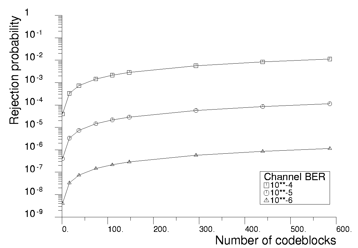 Figure: Frame rejection probability, PFY, in SEC mode using PLOP-2
Factors affecting frame undetected error rate
The second of the two performance criteria deals with the frame undetected error rate.
The use of SEC mode for codeblock decoding reduces the frame rejection rate but increases the probability of an undetected error in the frame. Section describes the different cases that arise during the decoding of BCH codeblocks. Table D-8 shows the cases that lead to undetected errors in the decoding process in SEC mode.
Table: Sources of undetected errors (SEC mode)
|
Case
|
Description
|
|
A2
|
The received codeblock has an even number of errors (at least 4) and the errors are not detected.
|
|
D2
|
The received codeblock has an odd number of errors (at least 3) and the SEC mode correction delivers a codeblock with an even number of errors (at least 2).
|
An upper bound for the occurrence of case A2 in a codeblock is given by adding the probabilities of 4, 6, 8, … errors occurring. Similarly, an upper bound for case D2 is given by adding the probabilities of 3, 5, 7, … errors occurring. As Table D-9 shows, the probabilities decrease rapidly as the number of errors increases, so the upper bound for case A2 can be considered to be the probability of four errors occurring in the codeblock and the upper bound for case D2 can be considered to be the probability of three errors occurring in the codeblock.
Table: Probability of n errors occurring in a codeblock
|
Number of errors, n
|
Channel Bit Error Rate
| ||
|
10-4
|
10-5
|
10-6
| |
|
1
|
6,26 x 10⁻³
|
6,30 x 10⁻⁴
|
6,30 x 10⁻⁵
|
|
2
|
1,94 x 10⁻⁵
|
1,95 x 10⁻⁷
|
1,95 x 10⁻⁹
|
|
3
|
3,95 x 10⁻⁸
|
3,97 x 10⁻¹¹
|
3,97 x 10⁻¹⁴
|
|
4
|
5,92 x 10⁻¹¹
|
5,95 x 10⁻¹⁵
|
5,96 x 10⁻¹⁹
|
|
5
|
6,99 x 10⁻¹⁴
|
7,02 x 10⁻¹⁹
|
7,03 x 10⁻²⁴
|
|
6
|
6,76 x 10⁻¹⁷
|
6,79 x 10⁻²³
|
6,79 x 10⁻²⁹
|
|
7
|
5,50 x 10⁻²⁰
|
5,53 x 10⁻²⁷
|
5,53 x 10⁻³⁴
|
|
8
|
3,85 x 10⁻²³
|
3,87 x 10⁻³¹
|
3,87 x 10-39
|
|
9
|
2,35 x 10⁻²⁶
|
2,37 x 10⁻³⁵
|
2,37 x 10-44
|
In a simulation of a decoder, all combinations of single, double, triple and quadruple errors were tested in SEC mode. The tests demonstrated that the decoder has an error-detection performance which is better than the upper bounds. The decoder performance is shown in Table D-10.
Table: Error detection performance when decoding a codeblock in SEC mode
|
Number of errors
|
Combinations
|
Performance in SEC
|
|
1
|
63
|
All corrected
|
|
2
|
1953
|
All detected
|
|
3
|
39711
|
651 detected
|
|
39060 undetected*
| ||
|
4
|
595665
|
585900 detected
|
|
9765 undetected
| ||
|
*In all these cases, the SEC correction delivers a codeblock with 4 errors.
| ||
The Frame Error Control Field gives protection against undetected errors. It is a 16-bit field providing a cyclic redundancy check (CRC) over the contents of the frame. At the receiving end, the Frame Error Control Field is validated by the frame error control procedure.
In the simulation, the performance of the CRC was analysed for the cases where the codeblock decoding delivers a codeblock with errors. The CRC performance for a frame with errors in more than one codeblock was also considered.
Table D-11shows the probabilities of an undetected error in a frame when the CRC is used. Figure D-2 shows a graph of the probabilities from Table D-11 and also shows the undetected error probabilities if the CRC is not used.
Table: Probability of undetected error in a frame, SEC mode, with CRC
|
Number of CodeblocksN
|
Channel Bit Error Rate
| ||
|
10-4
|
10-5
|
10-6
| |
|
2
|
2,55 x 10⁻²⁰
|
2,58 x 10⁻²⁶
|
2,58 x 10⁻³²
|
|
10
|
1,15 x 10⁻¹⁸
|
1,16 x 10⁻²⁴
|
1,16 x 10⁻³⁰
|
|
20
|
4,85 x 10⁻¹⁸
|
4,91 x 10⁻²⁴
|
4,91 x 10⁻³⁰
|
|
30
|
1,11 x 10⁻¹⁷
|
1,12 x 10⁻²³
|
1,12 x 10⁻²⁹
|
|
40
|
1,99 x 10⁻¹⁷
|
2,01 x 10⁻²³
|
2,02 x 10⁻²⁹
|
|
50
|
3,13 x 10⁻¹⁷
|
3,16 x 10⁻²³
|
3,17 x 10⁻²⁹
|
|
60
|
4,52 x 10⁻¹⁷
|
4,57 x 10⁻²³
|
4,58 x 10⁻²⁹
|
|
70
|
6,17 x 10⁻¹⁷
|
6,24 x 10⁻²³
|
6,24 x 10⁻²⁹
|
|
80
|
8,07 x 10⁻¹⁷
|
8,16 x 10⁻²³
|
8,17 x 10⁻²⁹
|
|
90
|
1,02 x 10⁻¹⁶
|
1,03 x 10⁻²²
|
1,04 x 10⁻²⁸
|
|
100
|
1,26 x 10⁻¹⁶
|
1,28 x 10⁻²²
|
1,28 x 10⁻²⁸
|
|
110
|
1,53 x 10⁻¹⁶
|
1,55 x 10⁻²²
|
1,55 x 10⁻²⁸
|
|
120
|
1,82 x 10⁻¹⁶
|
1,84 x 10⁻²²
|
1,85 x 10⁻²⁸
|
|
130
|
2,14 x 10⁻¹⁶
|
2,17 x 10⁻²²
|
2,17 x 10⁻²⁸
|
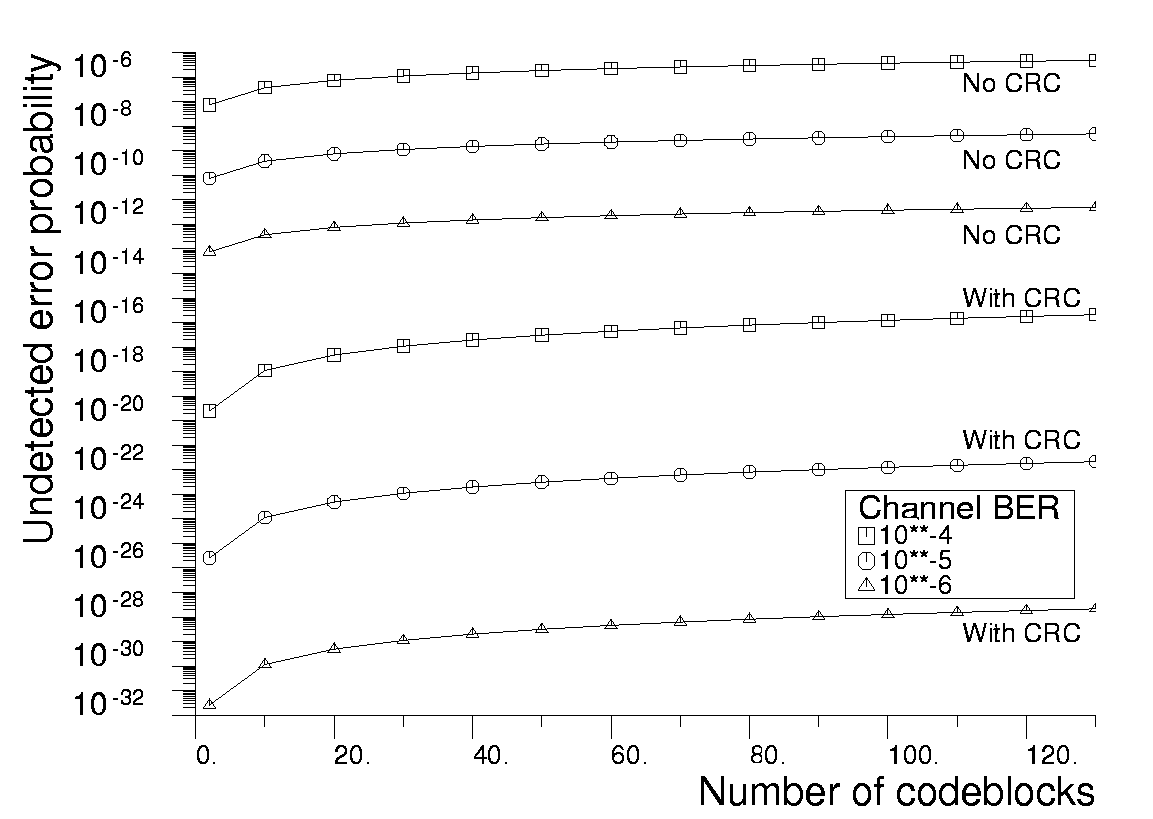 Figure: Probability of undetected error in a frame in SEC mode
ANNEX(informative) configuration parameters
Introduction
This annex provides a summary of the mission configuration parameters within the scope of this Standard.
This annex shows the options and values that can be taken by the parameters as specified in this Standard. It is the responsibility of mission designers to ensure the availability of support for the options and values selected for the mission.
Parameters of a physical channel
Overview
This clause describes the mission configuration parameters of a physical channel that carries TC Transfer Frames.
Fixed parameters
The following configuration parameters of a physical channel have values fixed by the requirements of this Standard:
A CLTU Start Sequence with a one-bit error is accepted.
The codeblocks of a CLTU are decoded in the error-correcting mode.
Pseudo-randomization is used.
A CLTU does not carry multiple TC Transfer Frames.
The Frame Error Control Field is present in all TC Transfer Frames.
Length of the acquisition sequence
The length of the acquisition sequence in the physical layer is a mission configuration parameter of a physical channel.
Physical layer operation procedure
This Standard defines two physical layer operation procedures, PLOP-2 and PLOP-1. The choice of the physical layer operation procedure is a mission configuration parameter of a physical channel.
If the physical layer operation procedure is PLOP-2, then the following configuration parameter of the physical channel has a value fixed by the requirements of this Standard:
In PLOP-2 the idle sequence between CLTUs is always used.
Transfer Frame Version Number
The Transfer Frame Version Number is a mission configuration parameter. For the TC Transfer Frames specified in this Standard it is set to '00', indicating a version 1 TC Transfer Frame. The value is constant for all frames of the physical channel.
A physical channel where the frames have any other value in the Transfer Frame Version Number is outside the scope of this Standard.
Maximum length of a TC Transfer Frame
The length of a TC Transfer Frame is an integer number of octets, up to 1024 octets. The maximum length of a frame is a mission configuration parameter of a physical channel.
Note that the maximum length of a CLTU and the maximum number of BCH codeblocks in a CLTU depend on the maximum length of a TC Transfer Frame.
Note also that the maximum frame length for the physical channel can be less than 1024 octets. However, it cannot be less than the maximum frame length for a virtual channel of the physical channel.
Virtual channels
A physical channel has one or more virtual channels. The list of identifier values for the virtual channels is a mission configuration parameter of the physical channel. Each virtual channel is identified by the Spacecraft Identifier (see also NOTE of clause 6.2.2.6) and the Virtual Channel Identifier fields of the TC Transfer Frame.
Use of the expedited service
There is a mission configuration parameter that defines the operational circumstances under which the expedited service of the transfer sublayer is used.
Multiplexing parameters
Issues concerning the multiplexing of virtual channels onto a physical channel, and the multiplexing of MAPs onto a virtual channel, are outside the scope of this Standard. Algorithms, priorities and other related parameters are mission dependent.
Parameters of a virtual channel
Overview
This clause describes the mission configuration parameters of a virtual channel.
Spacecraft Identifier and Virtual Channel Identifier
A virtual channel has specific values for the Spacecraft Identifier and the Virtual Channel Identifier of the TC Transfer Frame.
Maximum length of a TC Transfer Frame
The maximum length of a TC Transfer Frame is a mission configuration parameter of a virtual channel.
FOP-1 parameters
The values of the following FOP-1 parameters are mission configuration parameters for a virtual channel:
FOP_Sliding_Window_Width, K
Timer_Initial_Value, T1_Initial
Transmission_Limit
Timeout_Type, TT
The values can be set with the sequence-controlled service management interface defined in clause 7.4.2. The values can vary during a mission.
CLCW reporting rate
The CLCW reporting rate is a mission configuration parameter of a virtual channel. The rate can vary during a mission.
Status Field of CLCW
The use of the Status Field of a CLCW is a mission configuration parameter.
Fixed parameters
The following configuration parameters of a virtual channel have values fixed by the requirements of this Standard:
The CLCW Version Number is set to zero, indicating a Version-1 CLCW;.
The COP in Effect field of the CLCW is set to the value 1, indicating that COP-1 is in effect.
FARM-1 sliding window parameters
The values W, PW and NW for the FARM-1 sliding window are mission configuration parameters for a virtual channel. They can be fixed for the duration of the mission or for a mission phase.
Use of TC Segments
The use of TC Segments is a mission configuration parameter for a virtual channel.
Parameters of a virtual channel with TC Segments
Overview
This clause describes the additional mission configuration parameters of a virtual channel that uses TC Segments.
MAP Identifier values
A virtual channel with TC Segments uses up to 64 integer values for the MAP Identifier field of the TC Segments. The list of values is a mission configuration parameter of the virtual channel.
Parameters of a virtual channel without TC Segments
Overview
This clause describes the additional mission configuration parameters of a virtual channel that does not use TC Segments.
Use of the blocking function
The use of the blocking function is a mission configuration parameter of a virtual channel that does not use TC Segments.
If the virtual channel uses the blocking function then the higher layer data units which use the virtual channel are restricted to certain packet types. The mission configuration parameters for packet types are described inE.4.
Parameters of a MAP
Overview
This clause describes the mission configuration parameters of a MAP.
MAP Identifier
A MAP has a specific value for the MAP Identifier of the TC Segment.
Use of the blocking function
The use of the blocking function is a mission configuration parameter of a MAP. If the MAP uses the blocking function then the higher layer data units which use the MAP are restricted to specific packet types. The mission configuration parameters for packet types are described below.
Segmentation function
Use of the segmentation function
The use of the segmentation function is a mission configuration parameter of a MAP.
Maximum length of a user data unit
If a MAP uses the segmentation function, then it can carry user data units that are too long to fit in a single TC Transfer Frame. In this case, the maximum length of a user data unit is a mission configuration parameter of the MAP.
If the MAP does not use segmentation, then the maximum length of a user data unit is limited by the maximum length of the Transfer Frame Data Field of the TC Transfer Frames for the virtual channel.
If the MAP carries packets, then the maximum length applies to the packets.
Use of the packet assembly controller
If the MAP uses the segmentation function then the MAP can optionally use the packet assembly controller specified in clause 5.5.4 and the use of the packet assembly controller is a mission configuration parameter of the MAP.
Note that the packet assembly controller uses two MAP Identifiers.
Parameters for packet types
Overview
This clause describes the additional mission configuration parameters for packets on virtual channels and MAPs which use the blocking function.
Valid packet version numbers
The list of valid values for the Packet Version Number is a mission configuration parameter.
Bibliography
|
ECSS-S-ST-00
|
ECSS system – Description, implementation and general requirements
|
|
ECSS-E-ST-50
|
Space engineering - Communications
|
|
ECSS-E-ST-50-03
|
Space engineering – Space data links – Telemetry transfer frame protocol
|
|
ECSS-E-ST-50-05
|
Space engineering – Radio frequency and modulation
|
|
ECSS-E-HB-50
|
Space engineering – Communications guidelines
|
|
CCSDS 230.1G1
|
TC Synchronization and Channel Coding – Green Book, Issue 1, June 2006
|
|
CCSDS 231.0B1
|
TC Synchronization and Channel Coding – Blue Book, Issue 1, September 2003
|
|
CCSDS 232.0B1
|
TC Space Data Link Protocol – Blue Book, Issue 1, September 2003
|
|
CCSDS 232.1B1
|
Communications Operation Procedure-1 – Blue Book, Issue 1, September 2003
|
|
CCSDS 320.0-B-4
|
CCSDS Global Spacecraft Identification Field Code Assignment Control Procedures – Blue Book, Issue 3, January 2006
|
|
CCSDS 732.0-B-2
|
AOS Space Data Link Protocol – Blue Book, Issue 2, July 2006
|
|
CCSDS 912.3-B-1
|
Space Link Extension – Forward Space Packet Service Specification – Blue Book, Issue 1, November 2004
|
|
ESA-PSS-04-107
|
Packet telecommand standard, Issue 2, April 1992
|