
Space engineering
Gyro terminology and performance specification
Foreword
This Standard is one of the series of ECSS Standards intended to be applied together for the management, engineering and product assurance in space projects and applications. ECSS is a cooperative effort of the European Space Agency, national space agencies and European industry associations for the purpose of developing and maintaining common standards. Requirements in this Standard are defined in terms of what shall be accomplished, rather than in terms of how to organize and perform the necessary work. This allows existing organizational structures and methods to be applied where they are effective, and for the structures and methods to evolve as necessary without rewriting the standards.
This Standard has been prepared by the ECSS-E-ST-60-21C Working Group, reviewed by the ECSS Executive Secretariat and approved by the ECSS Technical Authority.
Disclaimer
ECSS does not provide any warranty whatsoever, whether expressed, implied, or statutory, including, but not limited to, any warranty of merchantability or fitness for a particular purpose or any warranty that the contents of the item are error-free. In no respect shall ECSS incur any liability for any damages, including, but not limited to, direct, indirect, special, or consequential damages arising out of, resulting from, or in any way connected to the use of this Standard, whether or not based upon warranty, business agreement, tort, or otherwise; whether or not injury was sustained by persons or property or otherwise; and whether or not loss was sustained from, or arose out of, the results of, the item, or any services that may be provided by ECSS.
Published by: ESA Requirements and Standards Division ESTEC, P.O. Box 299, 2200 AG Noordwijk The NetherlandsCopyright: 2017© by the European Space Agency for the members of ECSS## Change log
|
ECSS-E-ST-60-21C
|
First issue.
|
Introduction
This Standard is intended to support the variety of space borne gyros either available or under development, with the exception of the gyros used for the launch vehicles. Single-axis units are fully covered by this Standard and multiple-axes units are partially covered for axis level terminology, functional and performance specifications.
This standard defines the terminology and specifications for the functions and performance of gyros used on spacecraft. It focuses on the specific topics to be found in the gyros procurement specification documents and is intended to be used as a structured set of systematic provisions.
This standard is split in three main clauses:
Terminology (clause 3)
Functional requirements (clause 4)
Performance requirements (clause 5)
This standard does not contain textbook material on gyro technology. The readers and the users are assumed to possess general knowledge of gyro technology and its applications to space missions.
Scope
This Standard specifies gyros functions and performances as part of a space project. This Standard covers aspects of functional and performance requirements, including nomenclature, definitions, functions and performance metrics for the performance specification of space-borne gyros.
The Standard focuses on functional and performance specifications with the exclusion of mass and power, TM/TC interface and data structures. The Standard provides a general set of functional and performance specifications which are not depending on a particular gyro technology.
The requirements verification by test can be performed at qualification level only or also at acceptance level. It is up to the supplier, in agreement with the customer, to define the relevant verification approach in the frame of a specific procurement, in accordance with clause 5.2 of ECSS-E-ST-10-02.
The present standard does not cover gyro use for launch vehicles.
This standard may be tailored for the specific characteristics and constraints of a space project in conformance with ECSS-S-ST-00.
Normative references
The following normative documents contain provisions which, through reference in this text, constitute provisions of this ECSS Standard. For dated references, subsequent amendments to, or revision of any of these publications, do not apply. However, parties to agreements based on this ECSS Standard are encouraged to investigate the possibility of applying the more recent editions of the normative documents indicated below. For undated references, the latest edition of the publication referred to applies.
|
ECSS-S-ST-00-01
|
ECSS system - Glossary of terms
|
Terms, definitions and abbreviated terms
Terms from other standards
For the purpose of this Standard, the terms and definitions from ECSS-S-ST-00-01 apply, in particular the following terms:
acceptance
assembly
availability
configuration
failure
lifetime
performance
qualification
redundancy
Terms specific to the present standard
alignment reference frame (ARF)
frame that is fixed with respect to the gyro external optical cube where and whose origin is defined unambiguously with reference to the gyro external optical cube
- 1 The X, Y and Z axes of the ARF are a right-handed orthogonal set of axes which are defined unambiguously with respect to the normal of the faces of the external optical cube. Figure 31 schematically illustrates the definition of the ARF.
- 2 If the optical cube’s faces are not perfectly orthogonal, the X‐axis can be defined as the projection of the normal of the X‐face in the plane orthogonal to the Z‐axis, and the Y‐axis completes the RHR.
- 3 The ARF is the frame used to align the sensor during integration.
- 4 This definition does not attempt to prescribe a definition of the ARF, other than it is a frame fixed relative to the physical geometry of the sensor optical cube.
- 5 This term is defined in the present standard with a different meaning than in ECSS-E-ST-60-20. The term with the meaning defined herein is applicable only to the present standard.
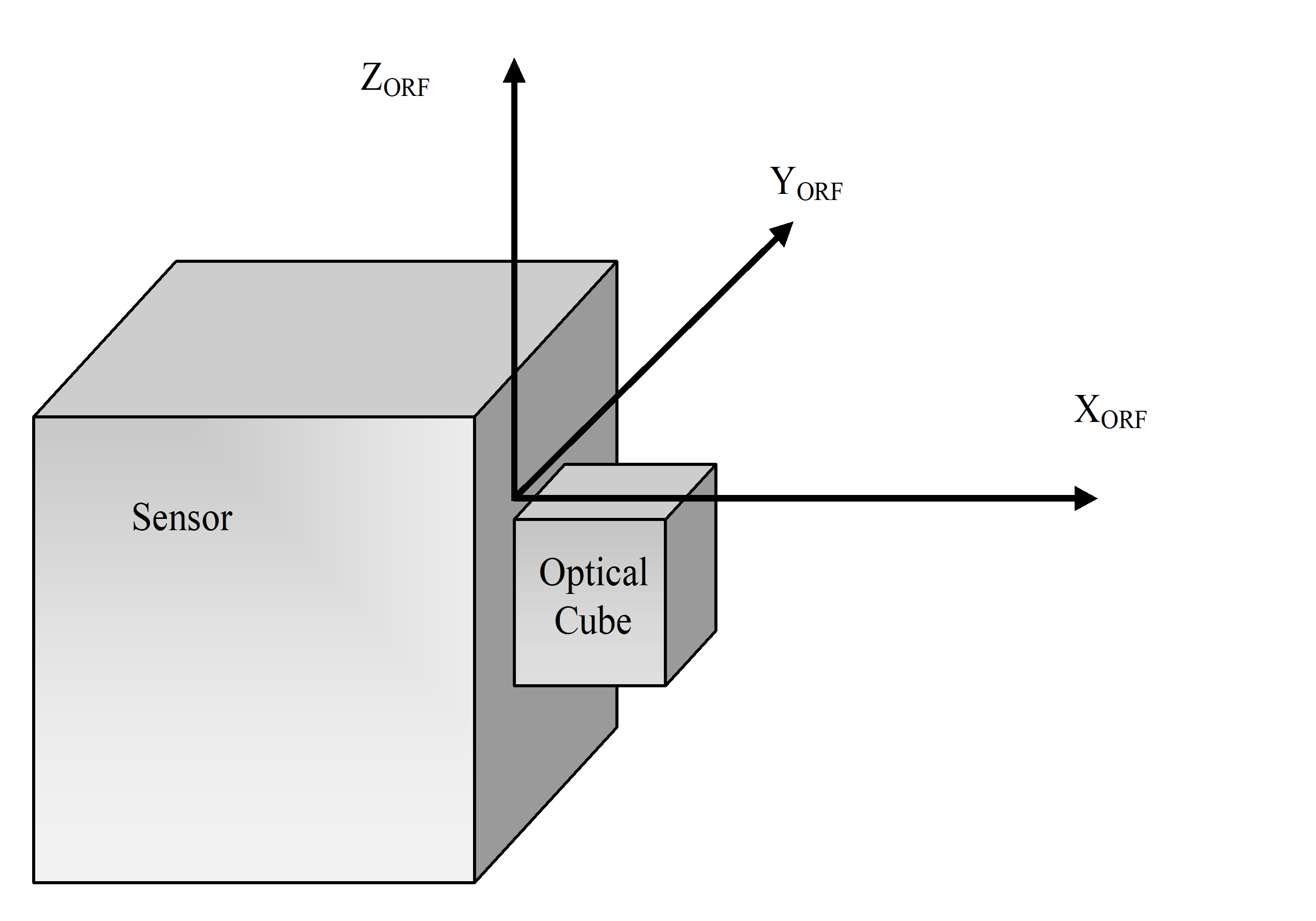 Figure 31: Example alignment reference frame
angle quantisation error
noise due to the discrete nature of the gyro internal processing and digital nature of the output
The angle quantisation noise has the same asymptotic behaviour than the AWN on Allan variance and PSD plots.
angular increment
angular rotation between two user requests or two consecutive gyro outputs
angular random walk (ARW)
white noise on the gyro rate output whose asymptotic behaviour corresponds to a -1 slope on the rate Allan variance plot, to a -1/2 slope on the rate Allan variance standard deviation plot and to a flat slope on the rate PSD plot
The plots are presented in log/log scale.
angular rate
time-rate of change of angular position of a rotating body
angular white noise (AWN)
white angle noise whose asymptotic behaviour corresponds to a -2 slope on the rate Allan variance plot, to a -1 slope on the rate Allan variance standard deviation plot and to a +2 slope on the rate PSD plot
The plots are presented in log/log scale.
anti-aliasing filter
filter implemented in the gyro in order to avoid the aliasing of the high frequency motion of the spacecraft input signal
bias
gyro measurement errors that are non-stochastic and not input rate dependant, computed as the average of the rate error value over a defined time period
This term is defined in the present standard with a different meaning than in ECSS-E-ST-60-20. The term with the meaning defined herein is applicable only to the present standard.
bias instability
low frequency noise component corresponding to flat slope on the rate Allan variance standard deviation plot and to a -1 slope on the rate PSD plot
- 1 The plots are presented in log/log scale.
- 2 Rate bias instability is also called rate flicker noise or pink rate noise.
calibration
set of activities based on a set of tests allowing to characterise the gyro non-random performance and, when relevant, to define the compensation parameters used to improve the performance
This term is defined in the present standard with a different meaning than in ECSS-S-ST-00-01. The term with the meaning defined herein is applicable only to the present standard.
configuration status
telemetry word indicating the states of the gyro tuneable settings
The configuration status scope is typically defined by the gyro supplier.
cumulated angular increments
summation of angular increments
cumulated increments data output do not correspond to an angular rotation between two requests but to a cumulated angular rotation. The customer typically manages the overflow. The use of cumulated angular increments is robust to transient data transmission losses.
deadband
input rotation range inside which the gyro output variation is less than a specified value of the movement applied variation
The specified value is normally expressed as a percentage of the movement applied variation.
frequency bandwidth
frequency range over which the sensor has the ability to provide a measurement of the signal
frozen outputs
situation occurring when the gyro output is erroneously identical over several measurement acquisitions despite variation of the input signal
health status
telemetry word which contains the gyro internal monitoring survey results
The internal monitoring survey parameters are defined by the gyro supplier.
input axis misalignment
angular error between the real sensing axis and the gyro reference sensing axis
input range
interval of input values to the unit for which specified performance is achieved
mechanical reference frame (MRF)
frame where the origin and axes are defined unambiguously with reference to the mounting interface plane of the gyro
- 1 For example the Z-axis of the MRF is defined to be perpendicular to the mounting interface plane, which is the recommended convention. The X and Y axes of the MRF are defined to lie in the mounting plane such as to form an orthogonal right hand rule reference frame (RHR) with the MRF Z‐axis.
- 2 Figure 32 schematically illustrates the definition of the MRF.
- 3 If the gyro consists of several units, each unit has its own MRF.
- 4 This term is defined in the present standard with a different meaning than in ECSS-E-ST-60-20. The term with the meaning defined herein is applicable only to the present standard.
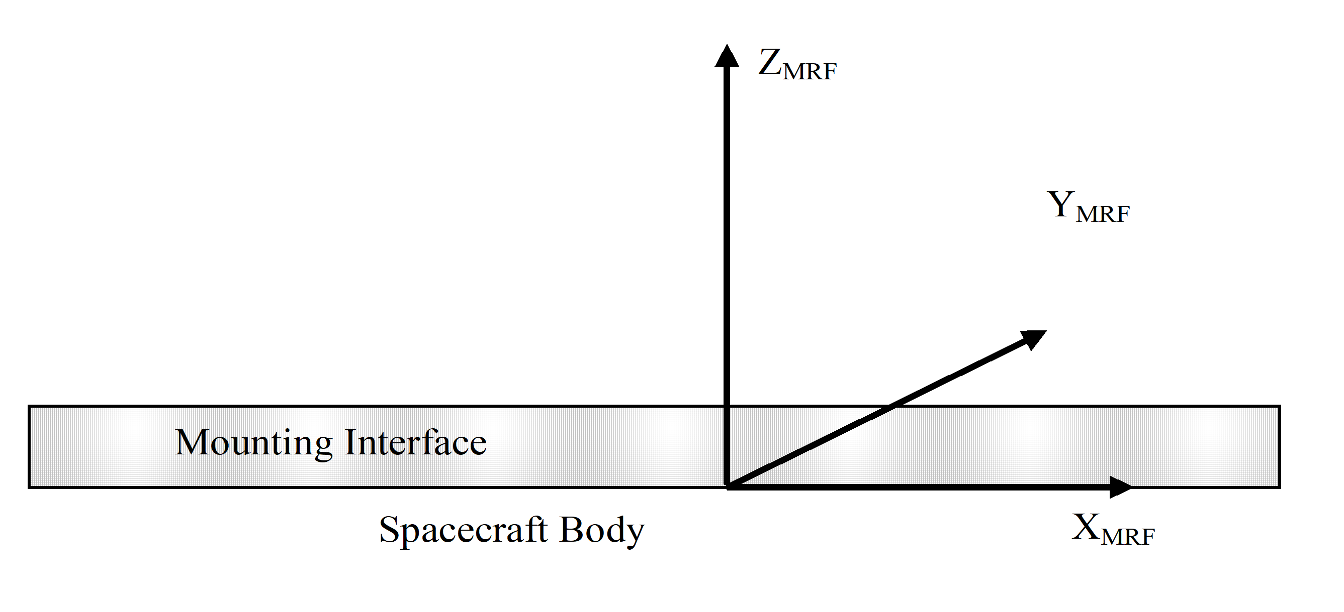 Figure 32: mechanical reference frame (MRF)
multiple-axis configuration
gyro configuration with several sensing axes on the same mechanical structure and oriented along different directions, physically defined w.r.t. the mechanical reference frame (MRF) or the alignment reference frame (ARF)
noise
high frequency or short duration errors
- 1 Noise measurements and noise model characterization can be done at various temperatures. However, during noise measurement, gyro channel environmental temperature is assumed identical within a specified temperature range.
- 2 This term is defined in the present standard with a different meaning than in ECSS-E-ST-32-11. The term with the meaning defined herein is applicable only to the present standard.
rate random walk (RRW)
white angular acceleration noise whose asymptotic behaviour corresponds to a +1 slope on the rate Allan variance plot, to a +1/2 slope on the rate Allan variance standard deviation plot and to a -2 slope on the rate PSD plot
The plots are presented in log/log scale.
repeatability
degree of closeness of test results taken during different periods of operations
- 1 For instance before and after thermal cycles and other environmental exposures, between power cycles and according to time between runs. Unless otherwise specified, measurements are carried-out in the same environmental conditions (in particular, gyro channel environmental temperature being assumed identical within a specified temperature range).
- 2 This term is defined in the present standard with a different meaning than in ECSS-E-ST-35 and ECSS-Q-ST-20. The term with the meaning defined herein is applicable only to the present standard.
scale factor error
gyro measurement errors that are non-stochastic and dependent on the rate applied on the input axis
scale factor non linearity
deviation of the output from a reference scale factor, over a given input range
the scale factor non linearity can be determined, for example, by a least square linear fit of the input/output data.
scale factor non linearity error
residual errors after compensation of the scale factor non linearity component
sensing reference frame (SRF)
physical reference frame in which individual gyro axes outputs are provided
- 1 In case of a single-axis configuration, the sensing axis is the Z-axis of the SRF.
- 2 The sensing axis alignment w.r.t. the reference frame (either MRF or ARF) is defined either by the unitary vector of the ZSRF expressed in the reference frame or by the transfer matrix between the SRF and the reference frame.
- 3 The sensing axis misalignments are the angular projections of the true Z sensing axis on the X_SRF and Y_SRF. Misalignment errors are expressed as half-cone errors, i.e. root-sum square of both projections.
sensitivity
variation induced by a given environmental change, all other environmental conditions being assumed unchanged and gyro channel being in continuous operation
An environmental change can be, for example, a change in temperature.
single-axis configuration
gyro configuration with only one sensing axis
stability
variation over a defined time period during which the gyro channel is continuously submitted to specific operating conditions
Unless otherwise specified, measurements are carried-out in the same environmental conditions (in particular, gyro channel environmental temperature being assumed identical within a specified temperature range).
start-up phase
time interval between the switch-on of the gyro unit and the presence of a valid output of the gyro that is fulfilling the pertaining performance requirements
An example of Start-up and Warm-up phases is given in Figure 41.
stimulation
function that allows to inject a simulated dynamic angular profile to the gyro for ground test purposes
validity flag
flag that indicates whether the gyro measurement output is valid for use
warm-up duration
time interval between the switch-on of the gyro unit and the time when the full nominal performances are achieved
An example of Start-up and Warm-up phases is given in Figure 41.
Abbreviated terms
For the purpose of this Standard, the abbreviated terms from ECSS-S-ST-00-01 and the following apply:
|
Abbreviation
|
Meaning
|
|
ARF
|
alignment reference frame
|
|
ARW
|
angular random walk
|
|
AWN
|
angular white noise
|
|
BOL
|
beginning-of-life
|
|
DRD
|
document requirements definition
|
|
EGSE
|
electrical ground support equipment
|
|
EOL
|
end-of-life
|
|
FMM
|
functional mathematical model
|
|
HK
|
housekeeping
|
|
MRF
|
mechanical reference frame
|
|
PPM
|
parts per million (10-6)
|
|
PSD
|
power spectral density
|
|
RHR
|
right hand rule
|
|
RRW
|
rate random walk
|
|
SEE
|
single event effect
|
|
SRF
|
sensing reference frame
|
|
TM
|
telemetry
|
|
w.r.t.
|
with respect to
|
Functional requirements
Overview
The gyro functional requirements address the following features:
Operating modes and transient behaviours
Timing aspects
Lifetime and duty cycle
Alignment and scale factor
Commandability and observability
Anti-aliasing
Stimulation
The list of unit functional requirements is not exhaustive and generic functional requirements (such as redundancy and reliability) are also considered in the frame of a gyro requirements specification.
The requirements listed in clause 4 can be complemented, as needed, with requirements found in ECSS-E-ST-10, ECSS-E-ST-10-03, ECSS-E-ST-60-30 and ECSS-E-ST-70-11.
Operating modes
Operating modes functional requirements
The gyro shall provide a Measurement Mode.
The TM data provided by the unit shall unambiguously report when the gyro has switched from Start-Up Mode to Measurement Mode.
The gyro shall perform a health-check at the end of the initialization phase.
The health check shall comprise, as a minimum:
- communications
- memories
- processor function
- detector function
The detector function is a support for failure diagnosis.
The gyro shall be capable to autonomously enter the measurement mode after power on.
It shall be possible to power off the gyro at any time and in any mode of operation without causing any damage to it.
The customer shall specify the transitions between the gyro operational modes and phases and the transient behaviours.
A mode status shall be present in the housekeeping data.
A reset capacity shall be available and commonly defined by the supplier and the customer.
Operating modes verification requirement
The operating mode requirements shall be verified by test during qualification and acceptance tests.
Start-up
Start-up functional requirements
The gyro channels shall provide valid inertial data on the interface bus after switch-on of the equipment within the maximum specified duration for any angular rate within its input range.
The start-up performance specified in clause 5.4.7 shall be achieved within the maximum specified duration after switch-on.
- 1 For some gyros, the start-up performances are reached at the time the validity bit is set.
- 2 An example of start-up is given in Figure 41.
Start-up verification requirements
The start-up duration shall be measured by external means.
The start-up requirement shall be tested over the whole range of operational temperatures and dynamics.
Warm-up
Warm-up functional requirements
The warm-up performance specified in clause 5.4.8 shall be achieved within a maximum duration after switch-on.
Warm-up verification requirements
The warm-up duration shall be measured by external means.
The warm-up requirements shall be tested over the whole range of operational temperatures and dynamics.
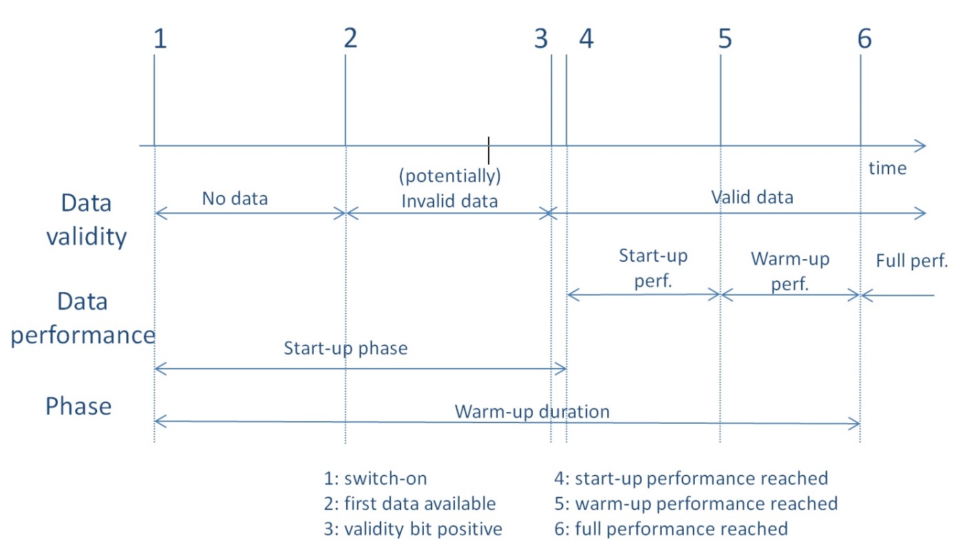 Figure 41: Example of Start-up and Warm-up phases
Time and frequency, datation and synchronisation
Time and frequency functional requirements
The gyro shall be capable to perform measurements together with the associated validity check and the sampling of housekeeping data at a frequency to be specified by the customer.
The sampling frequency is between some Hz and some tens of Hz depending on the application.
The data output of each gyro channel shall have its own date measurement related to a clock reference.
The clock reference can be either internal or external.
If a time tag counter is used, it shall not be reset after each reading.
This implies that the counter overflow is managed at user element level.
The output data shall be time tagged during data collection by the means of a frame counter or a time stamp.
The unit shall be able to work either in synchronous mode or in continuous mode.
When working in continuous mode, a time correlation mechanism shall be available to relate the gyro measurement date with the on-board time.
When working in synchronous mode, the angular inertial data measurement acquisition shall be synchronized with the external interrogation signal.
The angular inertial data measurements made available by the equipment are frozen.
When the gyro is working in synchronous mode, the external interrogation signal shall have an accuracy as specified in clause 5.4.6.
When the gyro is working in synchronous mode, the equipment shall offer also the possibility to choose the synchronisation signal amongst two options:
- a synchronisation signal on the chosen data interface - broadcast or unicast on the data Bus or dedicated command on serial link-, or
- a pulse on a synchro link interface.
Time and frequency verification requirements
The requirements of 4.5.1 shall be verified by test with an external clock reference.
Alignment and scale factor
Alignment and scale factor functional requirements
A transformation matrix shall be provided by the supplier.
The transformation matrix shall transform the sensitive axis/axes of each gyro unit into the reference frame, or frames.
The reference frame can be either MRF or ARF.
Scale factor of the gyro channels shall be positive when a positive rotation is applied around the sensing axis.
- 1 Positive scale factor means that angular increment is positive or cumulated angular increments output increases.
- 2 The positive rotation is intended in a trigonometric sense.
Alignment and scale factor verification requirements
The verification method of alignment and scale factor shall be proposed by the supplier for customer approval.
The transformation matrix w.r.t. the mechanical reference frame shall be measured before and after all the environmental tests performed during the qualification and acceptance phases.
The transformation matrix measured during the acceptance phase shall be delivered to the customer.
The customer shall choose the transformation matrix reference frame.
The reference frame can be either a mechanical reference frame or an alignment reference frame.
Commandability and observability
Commandability and observability functional requirements
The gyro shall provide in its periodic housekeeping data all the data required for the monitoring and execution of all nominal and foreseen contingency operations throughout the entire mission lifetime.
The gyro shall allow for on-request housekeeping data acquisition.
Commandability and observability verification requirements
The verification test shall be performed with a test set-up representative of the interface requirements specified by the customer
Failure diagnosis
Failure diagnosis functional requirements
The unit shall provide information in the housekeeping data allowing, in real time:
- detection of a single failure potentially degrading the measurement performances, or
- gyro loss of functionality. An analysis of the possible failures covered by the health status shall be provided.
Failure diagnosis verification requirements
The verification method for failure diagnosis shall be proposed by the supplier and agreed with the customer.
During the gyro test, the health status and the occurrence of false alarms on failure detection shall be continuously monitored.
Measurement mode
Measurement mode functional requirements
The measurement mode shall provide:
- measurement data, including an angular rate, an angular increment or a cumulated angular increment,
- a health status,
- a data validity flag, and
- a timetag.
The gyro shall output a temperature measurement.
If internal filtering or compensation is applied to the measurement, both raw and filtered or compensated data shall be provided.
The measurement bandwidth shall be specified for each of the following outputs: - angular rate, unfiltered or filtered, or
- an angular increment, unfiltered or filtered, or
- a cumulated angular increment, unfiltered.
For further details, see clause 5.4.9.
Measurement mode verification requirements
The measurement mode functional requirements shall be verified by test.
Auxiliary modes
Auxiliary modes functional requirements
The gyro shall provide a Test mode.
The use of the Test mode for the unit in-flight shall be specified if necessary.
The gyro shall provide a Programmable mode.
The in-flight protection against misuse of these Test and Programmable modes shall be implemented in agreement with the user specification.
Auxiliary modes verification requirements
The auxiliary modes functional requirements shall be verified by test.
Anti-aliasing filter
Anti-aliasing functional requirements
The equipment shall implement an anti-aliasing filter.
The anti-aliasing filter frequency shall be defined by the customer.
Anti-aliasing filter performances are defined in clause 5.4.10.
If using an anti-aliasing filter which can be disabled, performance shall be evaluated with and without the filter so that both raw and filtered outputs satisfy the performance requirements.
Anti-aliasing verification requirements
The anti-aliasing functional requirements shall be verified by test using the raw and filtered output data or stimuli data.
Stimulation
Stimulation functional requirements
It shall be possible to stimulate the gyro output by electrical means including a digital link via a dedicated test connector.
Further details are in clause 5.4.13.
The stimulation capability shall be compatible with the customer real time acquisition frequency
The real time acquisition shall be specified by the customer.
If required for test input, the supplier shall provide an Electrical Ground Support Equipment (EGSE).
The stimulation capability shall be inhibited in flight.
Stimulation verification requirement
The stimulation requirements shall be verified during the qualification and acceptance tests by comparing the gyro outputs with the stimuli.
Lifetime and duty cycle
Lifetime and duty cycle functional requirements
The customer shall specify the number of years for the unit on ground, with separately specified the amount of time of operation.
The customer shall specify the number of years during transfer and operational lifetime, with separately specified the amount of time of operation.
The number of ON/OFF cycles (for each channel) shall be specified for the ground storage period and for the transfer and operational lifetime period.
If any maintenance is required during the ground storage and on-board, it shall be defined by the supplier.
The on ground storage, handling and transport conditions shall be specified by the customer.
For example temperature and vibrations.
Lifetime and duty cycle verification requirement
The lifetime and duty cycle verification method shall be agreed between supplier and customer, depending on the gyro technology.
Gyro technology includes, for example, limited life items and wear-out parts.
Performance requirements
Use of the statistical ensemble
Overview
Performances have a statistical nature, because they vary with time and from one realization of a sensor to another.
Only an envelope of the actual performances can be provided. Central to this is the concept of a ‘statistical ensemble’, made of ‘statistical’ sensors (i.e. not necessarily built, but representative of manufacturing process variations) and observations (depending on time and measurement conditions).
Further details can be found in ESSB-HB-E-003, in particular on the statistical approaches to handle the statistical set of configurations.
The confidence levels are specified by the customer.
The conditions elected to populate the statistical ensemble are defined on a case-by-case basis for each performance parameter or for a group of performance parameters.
- 1 A performance confidence level of 95 % is equivalent to a 2 sigma confidence level for a Gaussian distribution.
- 2 A performance confidence level of 99,7 % used is equivalent to a 3 sigma confidence level for a Gaussian distribution.
Provisions
The worst-case performances shall be assessed by using the worst-case sensor of the statistical ensemble.
The statistical ensemble shall be characterized and agreed with the customer.
The performances shall be assessed by using the gyro EOL conditions agreed with the customer.
The EOL conditions include ageing effects and environmental effects.
Performance verification requirements
The test method to verify performance specification shall be justified by the supplier.
The validation of test raw data post-processing shall be demonstrated by the supplier.
The adequacy of test equipment accuracy shall be agreed with the customer.
The test success criteria shall be derived from the customer requirements taking into account the test setup error budget.
The test inputs shall be in accordance with the required observability in terms of operational range and in terms of the test resolution.
The validation of the post processing tools shall be performed using a set of reference or simulated data.
The Earth rotation rate shall be taken into account in the tests, as an input rate, or as a contributor to the raw gyro measurement.
The alignment of the unit in a local horizontal, local vertical (LVLH) frame and the latitude of the test site, are known in order to correct for Earth rotation rate.
The performance requirements verification shall be done with individual tests or by combined tests.
One test serves the verification of several performance requirements.
The unit calibration shall be performed before and after the whole set of environmental tests.
The stability of the initial and final compensation parameters shall be compliant w.r.t. the performance requirements.
The user shall state if raw or compensated measurements are used.
For gyro errors the thermal sensitivity shall be verified in the specified temperature range.
E.g. unit environmental temperature, unit internal temperatures, at electronics or at sensing level.
The testability limits shall be declared by the supplier and agreed by the customer.
The verification requirements listed in this clause can be complemented, as needed, with requirements found in ECSS-E-ST-10, ECSS-E-ST-10-02, ECSS-E-ST-10-03 and ECSS-E-ST-60-30.
General performance requirements
Each requirement or group of requirements shall indicate the relevant conditions to be considered, as follows:
- the performance conditions of the ‘statistical ensemble’ encompassing for EOL:
- worst-case unit temperature within specified range;
- worst-case temperature slope within specified range;
- worst-case radiation flux within specified range;
- the input rate limit and the measurement range(s)
- the maximum linear acceleration
- the deadband limit
- the launch loads
- the 1 g to 0 g effects
- the SEE
- the gyro warm-up effect
- the power line variation effect
- the ageing effect
- the (other) environmental effects (such as microvibrations, shocks and magnetic field)
As regards statement 5.3a.1, additional values for BOL can be given.
It shall be specified by the customer whether the PSD is computed as double-sided or as single-sided.
In the single-sided case, all the energy is on the positive frequency range. The single-sided PSD is the recommended specification.
General performance metrics
Overview and definition
Present Clause 5.4 presents the general performance metrics for the errors contributing to the gyro performances. In Annex B, an example of data sheet built on the performance metrics is given.
The following error equation for a single-axis gyro, or for each axis of a multiple axis gyro, introduces the performance metrics developed in Clause 5.4:
SF·Measurement = Rate + Bias + Noise
where
SF is the true gyro scale factor, that equals SF0*(1+) where SF0 is the reference scale factor and is the scale factor error.
The reference scale factor SF0 can be an estimate determined by the supplier, or the last estimate determined by the customer before the flight, or the last estimate determined on board during operation using non inertial sensors.
Measurement is the measured angular rate or the measured angular increment divided by the time interval between two measurements
Rate is the rate input along the sensing axis, it includes the misalignment error, i.e. it is the product of the misalignment matrix and the rate in the reference frame axes
Bias is the gyro output error not correlated to the input rate and not covered by the term Noise
Noise includes the time dependent terms, over a defined time scale, such as ARW, Bias instability (flicker rate noise), RRW, and quantisation.
Bias
General requirements
A confidence level for the bias shall be specified by the customer.
The statistical interpretation of the bias shall be specified by the customer.
The bias shall be specified for a defined range of temperature by the customer.
Figure 51 illustrates the bias computation from test data. The observation time T is clearly indicated. Observation time T does not exceed the maximum time interval specified for the Allan variance analysis. The best estimate of the bias is obtained for an observation time T corresponding to the time interval at which the value of the Allan variance is minimum.
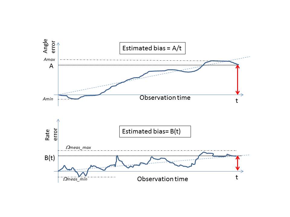 Figure 51: Examples of Bias estimation from test or simulation data
Bias performance requirements
General
The customer shall specify whether the bias specification requirements apply for compensated or uncompensated gyro outputs.
Bias value
The unit compensated bias value over an observation time T shall be specified by the customer denoting the performance type in terms of maximum, 1 sigma, 68 % confidence level or peak to peak.
The bias can exhibit harmonic behaviours depending of the sensor technology.
The unit uncompensated bias value over an observation time T shall be specified by the customer denoting the performance type in terms of maximum, 1 sigma, 68% confidence level or peak to peak.
The observation time T shall be specified by the customer.
Multiple observation times T, with associated performance conditions, can be specified.
Bias repeatability
The bias repeatability from switch-on to switch-on shall be specified by the customer denoting the performance type in terms of maximum, 1 sigma, 68% confidence level or peak to peak.
The on and off durations are specified.
The bias repeatability between before and after, mechanical environment application shall be specified by the customer denoting the performance type in terms of maximum, 1 sigma, 68% confidence level or peak to peak.
The bias repeatability between before and after thermal vacuum cycling shall be specified by the customer denoting the performance type such as maximum, 1 sigma, 68% confidence level or peak to peak.
The bias repeatability between before and after irradiation shall be specified by the customer denoting the performance type in terms of maximum, 1 sigma, 68% confidence level or peak to peak.
Depending of the gyro use, the repeatability requirements can be combined into a single specification.
Bias stability
The maximum rate bias over life shall be specified by the customer, as a maximum value over life.
The bias stability over a determined period of time shall be specified by the customer denoting the performance type, taking into consideration the environmental conditions between the bias measurements.
- 1 Environmental conditions include temperature variation, magnetic field variation, radiation, maximum linear acceleration and maximum angular acceleration.
- 2 Multiple time intervals with associated operating conditions can be specified.
- 3 The period of time over which the bias stability is specified can be hours, days or months.
Bias thermal sensitivity
The bias variation over operating temperature range shall be specified by the customer denoting the performance type in terms of maximum, 1 sigma, 68% confidence level or peak to peak.
Multiple temperature ranges within operating temperature range can be used to specify bias variation performances over these intervals.
The bias sensitivity to thermal gradient within a specific temperature range shall be specified by the customer denoting the performance type.
The operating temperature range and the thermal gradient, spatial or temporal, shall be specified as generic environmental conditions.
Other Bias sensitivity
The bias sensitivity to magnetic flux density for a customer-defined magnetic flux density range shall be specified by the customer denoting the performance type in terms of maximum, 1 sigma, 68% confidence level or peak to peak.
The bias sensitivity to specific force for a customer-defined specific forces range shall be specified by the customer denoting the performance type in terms of maximum, 1 sigma, 68% confidence level or peak to peak.
The bias sensitivity to micro-vibration in the specified microvibration environment shall be specified by the customer denoting the performance type.
Bias verification
Consideration on bias verification methods
It is necessary prior to estimate the bias to gain the knowledge of the scale factor and the applied input rate (i.e. orientation of the gyro input axis w.r.t. the Earth rotation axis). This dependency to alignment can be removed using a multi-orientation test.
The tests detailed in clause 5.4.2.3.2 do not necessarily require the knowledge of the bias but only a reference measurement together with guaranteeing the reference gyro orientation during each of the tests.
The uncompensated bias is the average of the uncompensated rate measurement output over the specified observation time t minus the rotation rate applied on the sensitive axis, including Earth rotation rate.
The compensated bias is the average of the compensated rate measurement output over the specified observation time t, minus the rotation rate applied on the sensitive axis, including Earth rotation rate.
The scale factor error has an effect on the computed bias. Scale factor error correction in the bias estimate is not necessary if its effect is one order of magnitude lower than the bias specification. Otherwise, scale factor error correction is necessary with a scale factor estimate done prior or simultaneously to the bias estimate.
Bias verification requirements
The duration of the test shall be long enough to obtain the required confidence level in the bias estimate.
For each given test, time T shall be consistent with the required bias estimate accuracy with justification.
- 1 The noise contribution to the bias estimate error is at a minimum lower than a third of the bias test criterion, ideally lower than a tenth of the bias test criterion.
- 2 Examples of Bias estimation from test or simulation data are given in Figure 51.
The bias repeatability shall be validated by test.
The bias repeatability from switch-on to switch-on shall be measured as follows: - Firstly, the bias is estimated prior to switch-off while the unit is in a stabilized state, after the warm-up phase.
- Secondly, the unit is switched off during a period long enough to reach a stabilized off state
- Thirdly, the unit is switched on again. After start-up and warm up duration, when the unit is again in stabilized state, a new bias estimate is performed.
An example of bias repeatability measurement is depicted in Figure 52.
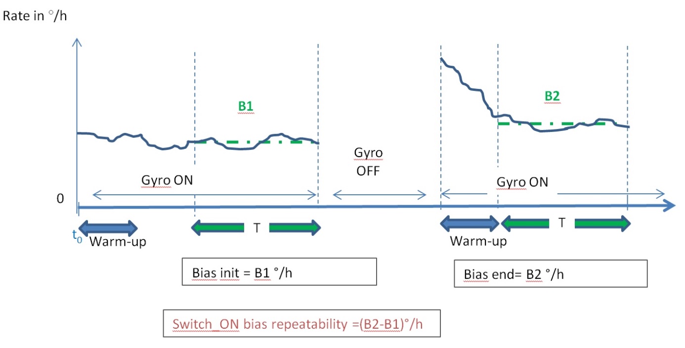 Figure 52: Switch-on bias repeatability computation
The bias repeatability between before and after, or after versus before, mechanical environment application, or between before and after thermal cycling, or before and after irradiation shall be estimated as follows:
- Firstly, the bias is estimated prior to the environmental test while the unit is in a stabilized state, after the warm-up phase.
- Secondly, the unit is submitted to the environmental test, with the on/off state of the unit during the test as specified.
- Thirdly, the bias is estimated after the environmental test while the unit is in a stabilized state, after the warm-up phase. The bias stability shall be estimated as follows:
- The bias is estimated periodically over the specified periods in clauses 5.4.2.2.2 and 5.4.2.2.4 while the unit is in a stabilized state.
- The bias stability is computed using all the bias estimates over the specified periods.
An example of bias stability measurement is depicted in Figure 53.
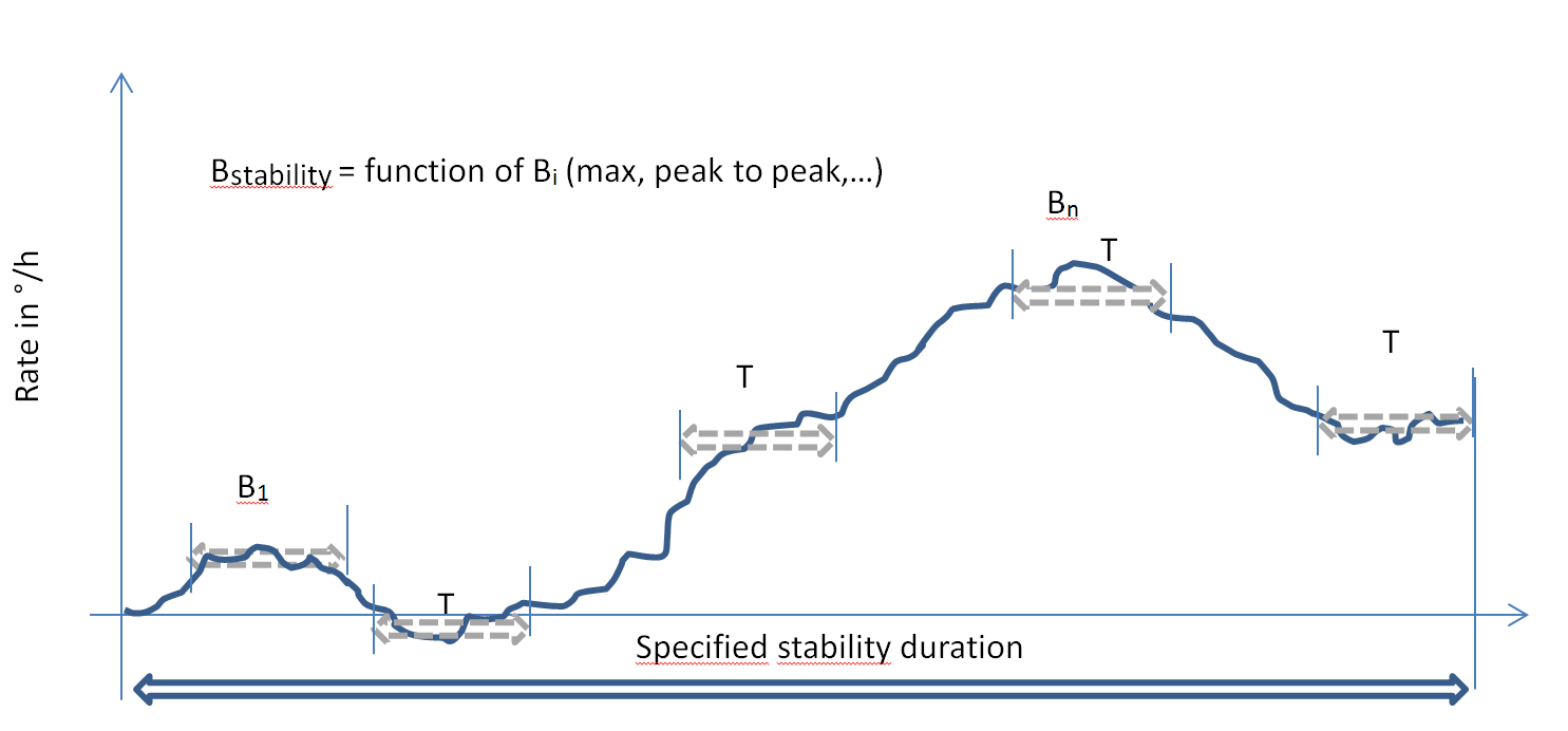 Figure 53: Bias stability computation
The bias sensitivity, with the exception of the thermal gradient sensitivity, shall be measured in stable environmental conditions and after internal stabilisation of the gyro consistent with the accuracy of the bias estimate specified in the test plan.
The thermal gradient sensitivity shall be measured during temperature ramp tests, using both positive and negative slopes, in the specified temperature range.
Different temperature slopes can be applied.
Noise
General requirements
The confidence level of the gyro noise terms shall be specified by the customer.
The statistical interpretation of the gyro noise terms shall be defined by the customer.
The performance of the gyro noise shall be specified under the related general performance conditions.
Noise performance requirements
The gyro noise, on each channel, shall be specified by the customer by:
- a mono lateral PSD template, or
- an Allan variance standard deviation template, or
- the contributors listed in requirement 5.4.3.2b. When fulfilling requirement 5.4.3.2a the following noise requirements shall also be achieved:
- the maximum customer-specified Angular White Noise (ϕ) contribution, sampled at a customer-defined frequency;
- the maximum customer-specified Angular Quantisation Noise (Q) contribution;
- the maximum customer-specified Angular Random Walk Coefficient (N);
- the maximum customer-specified Bias coefficient (B);
- the maximum customer-specified Rate Random walk coefficient (K);
- the maximum customer-specified Rate ramp coefficient (R).
- 1 The Bias instability is also called rate flicker noise.
- 2 Depending on the gyro technology and the mission needs, part of the contributors can be ignored.
- 3 For specific user need, other requirements can be added. For example:
- the integrated gyro noise error over a defined period can be specified on each gyro channel, denoting the performance type.
- the customer can specify, for a defined sampling rate and over a defined frequency range, the integrated single-sided PSD of the rotation rate (or angle). This approach is of interest in case of sine signals present in the noise signal.
- 4 For rate output gyros, rate quantization noise is covered by rate white noise (ARW) and bias instability (B)
Noise performance verification requirements
The measurement of the noise shall be performed via ground test.
The gyro error model coefficients shall be determined from Allan variance measurements or mono-lateral PSD measurements.
Figure 54 indicates equivalences between both formalisms.
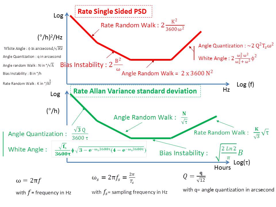 Figure 54: Single-sided rate PSD and Allan Variance Standard Deviation
For Allan variance measurement, the test duration shall be sized according to the specified confidence level.
For example, for 25 % error, the Allan variance test duration is at least 9 times longer than the specified Allan variance longest observation time (see equation C-22 in IEEE Std 647-2006 or IEEE Std 952-1997(R2008), both standards being also referred to in IEEE Std 1431-2004).
For mono lateral PSD measurement, the frequency resolution and the number of frequency spectrum to be averaged shall determine the test duration.
- 1 The Allan variance and PSD analyses on the required time and frequency domains can be split in several tests with different integration times, acquisition frequencies and durations.
- 2 If required, noise tests are performed at different temperatures within the operating temperature range, with a special care to the test facility environment noise.
Scale factor error
General requirements
The confidence level of the scale factor error shall be specified by the customer.
The statistical interpretation of the scale factor error shall be defined by the customer.
The performance of the scale factor error shall be specified under the related performance general conditions.
No random content in the scale factor error is considered in clause 5.4.4.
Scale factor performance requirements
Scale factor initial value
The compensated scale factor initial value shall be specified by the customer.
The uncompensated scale factor initial value shall be specified by the customer.
The scale factor initial value shall be determined with an accuracy specified by the customer.
Deadband
The gyro measurement deadband limits and maximum error shall be specified by the customer.
- 1 This requirement covers the case of scale factor non linearity within the measurement deadband.
- 2 Scale factor non-linearity error
The scale factor non-linearity error shall be specified by the customer denoting the performance type in terms of maximum, 1 sigma, 68% confidence level or peak to peak, for defined ranges of input rates.
In the range of low angular rate outside of the deadband range, the scale factor non-linearity error shall be specified by the customer denoting the performance type in terms of maximum, 1 sigma, 68% confidence level or peak to peak.
The customer can define an input range smaller than the deadband range.
Scale factor repeatability
the scale factor repeatability from switch-on to switch-on shall be specified by the customer denoting the performance type in terms of maximum, 1 sigma, 68% confidence level or peak to peak.
the on and off durations shall be specified.
the scale factor repeatability between before and after, or after versus before, mechanical environment application shall be specified by the customer denoting the performance type in terms of maximum, 1 sigma, 68% confidence level or peak to peak.
the scale factor repeatability between before and after thermal vacuum cycling shall be specified by the customer denoting the performance type in terms of maximum, 1 sigma, 68% confidence level or peak to peak.
the scale factor repeatability between before and after irradiation shall be specified by the customer denoting the performance type in terms of maximum, 1 sigma, 68% confidence level or peak to peak.
Depending of the gyro use, the repeatability values can be combined into a single specification.
Scale factor stability
The scale factor stability over a defined time period shall be specified by the customer denoting the performance type in terms of maximum, 1 sigma, 68% confidence level or peak to peak, taking into consideration environmental conditions between the scale factor measurements.
- 1 Environmental conditions include temperature variation, magnetic field variation, radiation, maximum linear acceleration and maximum angular acceleration.
- 2 Multiple time intervals with associated operating conditions can be specified.
Scale factor thermal sensitivity
The scale factor variation over the defined operating temperature range shall be specified by the customer denoting the performance type in terms of maximum, 1 sigma, 68% confidence level or peak to peak.
The scale factor variation over a defined temperature range within the operating temperature range shall be specified by the customer denoting the performance type in terms of maximum, 1 sigma, 68% confidence level or peak to peak.
The operating temperature range shall be specified.
Scale factor verification requirements
The measurement of the scale factor error shall be performed via ground test with a motion table.
The test sequence shall include test with positive and negative rate values.
The estimation of the scale factor shall include considerations on the bias knowledge and the applied input rate.
- 1 For example the orientation of the gyro input axis w.r.t. the motion table axis and the Earth rotation axis.
- 2 It is good practice to align the gyro sensing axis with the motion table rotation axis and to perform measurement over complete revolutions, in order to limit to second order of magnitude the contribution of alignment error and of Earth rotation projection along the gyro perpendicular axes.
- 3 Depending on the orientation of the sensing axis on the motion table and on the measurement required accuracy, an estimate of the alignment error can be required prior or simultaneously to the scale factor estimate.
The scale factor estimate shall be processed using an external precise time reference
The external time reference is usually provided by the test facility.
The gyro time tag shall not be used to process the estimate of the scale factor.
This is to exclude the time tag error from the scale factor budget.
The uncompensated scale factor shall be computed as the average of the ratio between the rotation rate applied on the sensitive axis and the uncompensated rate measurement output over the specified observation time T
The rotation rate includes the Earth rotation rate.
The compensated scale factor shall be computed as the average of the ratio between the rotation rate applied on the sensitive axis and the compensated rate measurement output over the specified observation time T.
- 1 � The rotation rate includes the Earth rotation rate.
- 2 The bias has an effect on the computed scale factor. Bias correction in the scale factor estimate is not necessary if its effect is one order of magnitude lower than the scale factor error specification. Otherwise, bias correction is necessary with a bias estimate done prior or simultaneously to the scale factor estimate.
- 3 The noise has an effect on the computed scale factor. To limit the noise effect on the scale factor estimate, the duration and number of revolutions of the scale factor test are adequately determined (e.g. the noise contribution is not larger than typically 10 % of the scale factor error requirement).
The scale factor error verification shall be based on, at least, measurements over the whole operational input range, with an adequate granularity.
This is especially valid at low input rates where test duration is very long.
The deadband range and performance verification shall be based on measurements with a sufficient input rate resolution and excursion.
The scale factor error repeatability from switch-on to switch-on shall be measured as follows.
- Firstly, the scale factor is estimated prior to switch-off while the unit is in a stabilized state, after the warm-up phase.
- Secondly, the unit is switched off during a period long enough to reach a stabilized off state.
- Thirdly, the unit is switched on again while the motion table is still rotating and, after start-up and warm up duration, when the unit is again in stabilized state, a new scale factor estimate is performed. The scale factor error repeatability between before and after, or after versus before, environmental tests shall be measured as follows:
- Firstly, the scale factor is estimated prior to the environmental test while the unit is in a stabilized state, after the warm-up phase
- Secondly, the unit is submitted to the environmental test. The on/off state of the unit during the test is specified.
- Thirdly, the scale factor is estimated after the environmental test while the unit is in a stabilized state, after the warm-up phase.
The environmental tests can include mechanical environment application, thermal vacuum cycling, or irradiation.
The scale factor stability shall be measured as follows:
- Firstly, the scale factor is estimated periodically over the specified periods in 5.4.4.2 while the unit is in a stabilized state.
- Secondly, the scale factor stability is computed using all the scale factor estimates over the specified period.
The periodicity of the scale factor estimate over the specified periods is defined and agreed with the customer.
The scale factor sensitivity shall be measured in stable environmental conditions and after internal stabilisation of the gyro consistent with the required accuracy of the scale factor estimate.
Scale factor errors verification shall not be done without verification of the measurement accuracy of the set‐up used for calibration.
Misalignment
General requirements
The confidence level of the misalignment error shall be specified by the customer.
Alignment errors shall be considered as “half cone” values.
The statistical interpretation of the misalignment error shall be defined by the customer.
The misalignment shall be verified by test.
Misalignment performance requirements
Absolute/relative alignment error
The angular error of the gyro sensors sensitive axes alignment w.r.t. their theoretical orientation, defined w.r.t. the gyro mechanical reference frame, shall be specified by the customer denoting the performance type in terms of maximum, 1 sigma, 68% confidence level or peak to peak.
The relative angular error of the gyro sensors sensitive axes alignment, one with respect to another, shall be specified by the customer.
Absolute/relative alignment knowledge
The knowledge accuracy of the alignment between the gyro sensors sensitive axes and the gyro mechanical reference frame shall be specified by the customer denoting the performance type in terms of maximum, 1 sigma, 68% confidence level or peak to peak, including all measurement uncertainties from launch, micro-gravity, outgassing, moisture release and thermo-elastic effects.
The knowledge accuracy of the alignment between the gyro sensors sensitive axes and the gyro alignment reference frame at unit delivery shall be specified by the customer denoting the performance type in terms of maximum, 1 sigma, 68% confidence level or peak to peak.
Alignment repeatability
The repeatability between before and after, or after versus before, mechanical environment application of the absolute gyro axes alignment w.r.t. mechanical reference frame shall be specified by the customer, irrespective of the off time duration.
The repeatability between before and after, or after versus before, thermal vacuum cycling of the absolute gyro axes alignment w.r.t. mechanical reference frame shall be specified by the customer, irrespective of the off time duration.
The relative gyro axes alignment, one w.r.t. another, repeatability between before and after, or after versus before, mechanical environment application shall be specified by the customer, irrespective of the off time duration.
The relative gyro axes alignment, one w.r.t. another, repeatability between before and after, or after versus before, thermal vacuum cycling shall be specified by the customer, irrespective of the off time duration.
Alignment stability
The absolute gyro axes alignment, w.r.t. mechanical reference frame, stability over a customer-defined time period shall be specified by the customer denoting the performance type in terms of maximum, 1 sigma, 68% confidence level or peak to peak, taking into consideration environmental conditions between the alignment measurements.
The relative gyro axes alignment, one w.r.t. another, stability over a customer-defined time period shall be specified by the customer denoting the performance type in terms of maximum, 1 sigma, 68% confidence level or peak to peak, taking into consideration environmental conditions between the alignment measurements.
Multiple time intervals with associated operating conditions can be specified.
Alignment thermal sensitivity
The absolute gyro axes, w.r.t. mechanical reference frame, alignment variation over operating temperature range shall be specified by the customer denoting the performance type in terms of maximum, 1 sigma, 68% confidence level or peak to peak.
The relative gyro axes alignment, one w.r.t. another, variation over operating temperature range shall be specified by the customer denoting the performance type in terms of maximum, 1 sigma, 68% confidence level or peak to peak.
The absolute gyro axes, w.r.t. mechanical reference frame, alignment variation over a customer-defined temperature range within the operating temperature range shall be specified by the customer denoting the performance type in terms of maximum, 1 sigma, 68% confidence level or peak to peak.
The relative gyro axes, one w.r.t. another, alignment variation over a customer-defined temperature range within the operating temperature range shall be specified by the customer denoting the performance type in terms of maximum, 1 sigma, 68% confidence level or peak to peak.
The operating temperature ranges shall be specified.
Misalignment performance verification requirements
The measurement of the alignment errors shall be performed via ground test with a motion table.
The estimation of the alignment errors shall include the knowledge of the bias, the scale factor, and the applied input rate.
- 1 A recommended good practice is to align the gyro sensing axis perpendicular to the motion table rotation axis (consecutively for both perpendicular orientations) and to perform measurement over complete revolutions, in order to limit to second order of magnitude the contribution of scale factor error and of Earth rotation projection along the gyro sensing axis.
- 2 For example, the orientation of the gyro input axis w.r.t. the motion table axis and the Earth rotation axis is provided.
The alignment errors repeatability between before and after, or after versus before, environmental tests shall be measured as follows: - Firstly, the alignment errors are estimated prior to the environmental test while the unit is in a stabilized state, after the warm-up phase.
- Secondly, the unit is submitted to the environmental test. The on/off state of the unit during the test is specified.
- Thirdly, the alignment errors are estimated after the environmental test while the unit is in a stabilized state, after the warm-up phase.
Environmental tests can include mechanical environment application, thermal vacuum cycling, or irradiation.
The alignment errors stability shall be measured as follows:
- The alignment errors are estimated periodically over the specified periods in 5.4.4.2 while the unit is in a stabilized state.
- 1 The periodicity of the alignment errors estimate over the specified periods is defined and agreed with the customer.
- 2 The alignment errors stability are computed using all the alignment errors estimates over the specified period
The alignment errors sensitivity shall be measured in stable environmental conditions and after internal stabilisation of the gyro consistent with the required accuracy of the alignment errors estimate.
Alignment errors verification shall not be done without verification of the measurement accuracy of the set‐up used for calibration.
Measurement datation and latency
General requirements
The confidence level of the measurement datation and latency performance shall be specified by the customer.
The statistical interpretation of the measurement datation and latency performance shall be defined by the customer.
Measurement datation and latency performance requirements
Measurement Datation accuracy
The gyro shall provide with its output data a time tag (internal time of inertial measurement).
The time tag quantisation shall be specified by the customer.
The time tag scale factor error shall be specified by the customer.
The time tag jitter shall be specified by the customer.
- 1 Multiple time intervals and temperature ranges with associated operating conditions can be specified for the time tag scale factor error.
- 2 The time tag jitter is considered as the maximum variation of the measurement datation errors between two consecutive time tags.
Synchronization performances
The delay between the synchronisation command and gyro axes measurement date shall be specified by the customer.
This includes either synchronisation on data bus or external synchronisation.
Latency
The latency between the gyro measurement availability on the databus and the reception of the TM command shall be specified by the customer.
The latency between the measurement date and the availability date on the databus shall be specified by the customer.
Measurement datation and latency verification requirements
The measurement datation and latency requirements should be verified by analysis, except for time tag scale factor.
The time tag scale factor may be characterised by test by monitoring of the time tag evolution on a significant period versus an external time reference.
Start-up performances
General requirements
The confidence level of the start-up performances shall be specified by the customer.
The statistical interpretation of the start-up performances shall be defined by the customer.
Start-up performance requirements
The measured rate error, or the measured angular increment error over the time interval between the two measurements, at the end of the unit start-up shall be specified by the customer as a ratio of the input angular rate with a specified maximum absolute error.
Start-up performance verification requirements
The start-up performance requirement shall be verified by test, covering the operational input range and operational environmental conditions.
Warm-up phase performances
General requirements
The confidence level of the warm-up phase performances shall be specified.
The statistical interpretation of the warm-up phase performances shall be defined.
Warm-up performance requirements
The maximum integrated gyro drift over the warm-up phase shall be specified by the customer.
The customer may specify performance requirements for the warm-up phase:
- bias (as per clause 5.4.2),
- noise (as per clause 5.4.3),
- scale factor error (as per clause 5.4.4), and
- misalignment errors (as per clause 5.4.5).
Warm-up performance verification requirements
The warm-up performance requirements shall be verified by test.
Except if specified otherwise, the test shall be performed under stabilised environmental conditions.
Depending on the requirements defined, the same verification methods as in clauses 5.4.2.3, 5.4.3.3, 5.4.4.3, and 5.4.5.3 shall apply.
Measured output bandwidth
Measured output bandwidth performance requirements
The gyro measured output bandwidth shall be specified by the customer.
Measured output bandwidth Verification methods
The output bandwidth shall be verified by test, by applying a sinusoidal input with frequency up to the level defined by the bandwidth requirement and comparing the gyro output to the applied movement.
Anti-aliasing filter
General requirements
The anti-aliasing filter requirement shall be consistent with the sampling requirement and the output bandwidth requirement.
Anti-aliasing performance requirements
The anti-aliasing filter shall be defined by a frequency template, in which attenuation and phase are function of the frequency.
As an example, the anti-aliasing filter performances can be defined as follows:
- Static gain: 0 dB
- Maximum phase @Fr/16: 6°
- Maximum overshoot: +3 dB
- Maximum attenuation @Fr: -3 dB
- Minimum attenuation @ 6,25Fr: -14 dB
where the filter frequency (Fr) is lower than half the sampling frequency (Fs).
Anti-aliasing performance verification requirements
The anti-aliasing filtering shall be verified by test.
Different methods can be used: for example, with stimuli input, comparison of unfiltered/filtered data, stimulation on the test bench as per output bandwidth measurement.
Data quantisation
Data quantisation performance requirements
The data quantisation shall be specified by the customer.
- 1 The output register sizing is consistent with the input range, the acquisition frequency and the data quantisation.
- 2 The data quantisation is consistent with the gyro quantisation noise performance requirement.
Data quantisation verification requirements
The data quantisation shall be verified by test.
Failure detection efficiency
Failure detection performance requirements
In measurement mode, the gyro failure detection coverage shall be specified by the customer as a percentage.
For gyro failure leading to degraded performance outside of the specified requirement values, the degraded performance envelope shall be defined.
In measurement mode, the risk of false alarm by the failure detection function shall be specified by the customer as a percentage.
Failure detection verification requirements
The failure detection efficiency requirements should be verified by analysis.
Stimulation
Stimulation performance requirements
The performance of the stimulation function shall be specified.
The stimulation function performance can be specified as follows:
- “The stimuli resolution shall be better than 0,1 deg/h.”
- “The stimuli scale factor error shall be better than 1 %.”
Stimulation verification requirements
The stimulation performance requirements shall be verified by test.
Functional and performance mathematical model
The customer may ask the supplier to provide a temporal functional and performance mathematical model of the gyro.
The functional and performance mathematical model shall be in accordance with the DRD in Annex A.
The functional and performance mathematical model shall be representative of the sensor actual performances for specified kinematic profiles.
The functional mathematical model shall include environmental parameters.
The functional mathematical model shall model all the performance errors defined in the performance requirements.
The functional mathematical model shall include the following items:
- the stimuli
- the reference frames projection
- the measurement deadband
- the anti-aliasing filter
- the integration and sampling
- the datation error
- the delays
- the misalignment and scale factor error, with or without compensation
- the bias, with or without compensation
- the bias dependency to environmental conditions, if compensation, to temperature measurement error
- the scale factor error dependency to environmental conditions, if compensation, to temperature measurement error
- the noise model, including ARW, AWN, RRW, rate flicker noise and quantisation
- the saturation
- the functional failures
- 1 A state machine can be introduced if transient behaviours (such as warm-up phase) need to be modelled.
- 2 Examples of functional failures are degradation of performance and frozen outputs.
- 3 As an example, a schematic of the functional mathematical model is proposed in Figure 55.
The functional mathematical model parameters may be represented by a single value or include nominal and worst-case values
A naming convention shall be defined for the functional mathematical model parameters and variables.
The functional mathematical model fidelity shall be validated denoting the actual temporal performances of the sensor over the specified environmental envelope
The functional mathematical model validation is performed with test scenarios and cases defined by the gyro supplier. The success criteria of the simulated validation cases are correlated to the gyro unit tests results.
 Figure 55: Example of Functional Mathematical Model Architecture
ANNEX(normative)Functional and performance mathematical model (FMM) description - DRD
DRD identification
Requirement identification and source document
This DRD is called from ECSS-E-ST-60-21, requirement 5.5b.
Purpose and objective
The functional mathematical models are established to serve as input for detailed AOCS analyses and detailed performance simulations.
Expected response
Scope and content
Introduction
The FMM description shall contain a description of the purpose, objective, content and the reason prompting its preparation.
The FMM description shall state and describe any open issues, assumptions and constraints.
The FMM description shall describe in detail the status and limitations of the model.
Applicable and reference documents
The FMM description shall list the applicable and reference documents in support to the generation of the document.
Definitions and abbreviations
The FMM description shall list the applicable directory or glossary and the meaning of specific terms or abbreviations utilized in the FMM.
Functional mathematical model (FMM)
The FMM description shall document the steps from the actual angular rate in inertial frame to the gyro outputs.
The outputs of the FMM shall include as a minimum:
- the measured angular rate and time delivered by the gyro;
- the gyro health status.
The outputs of the FMM shall include the outputs of the gyro detailed in clause 4, according to the sensor capabilities.
The parameters of the FMM shall be documented.
The FMM description shall indicate modelling constraints and critical implementation issues and their relevance on performance.
The FMM description shall present the expected temporal outputs of the gyro model for given input profiles.
Software tools
The software tools to be used for development of the FMM shall be specified.
Files and lists
The following information shall be attached to the FMM description:
- identification of delivered computer files;
- FMM source lists based on applied tools.
ANNEX(informative)Example of data sheet
Introduction
The data sheet in Figure B-1 shows an example of data sheet for gyros.
The fields that can be filled in are identified in an italic font.
The example values filled in are just for formatting purposes and do not relate to an existing gyro.
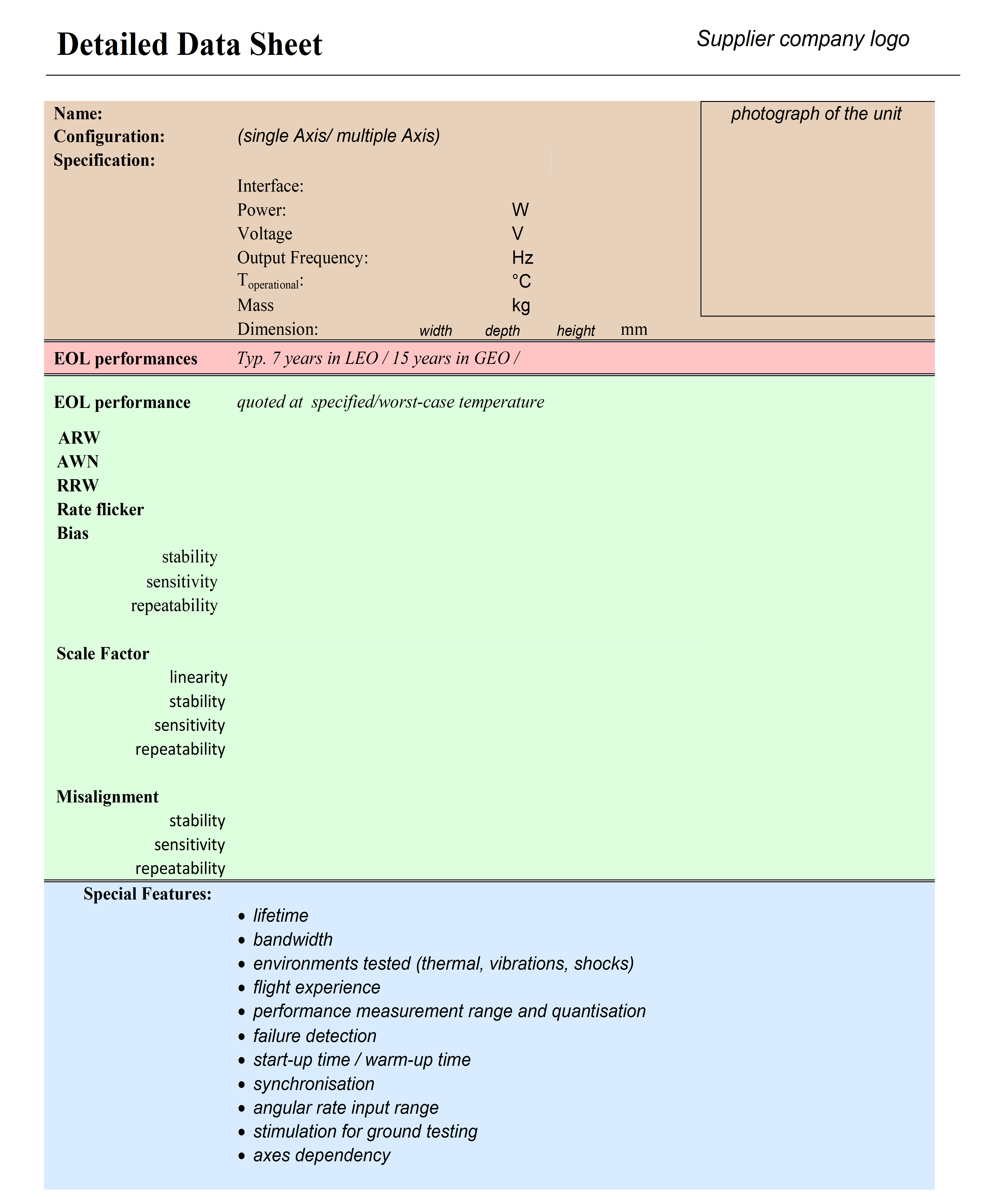 Figure: Example of detailed gyro data sheet
Bibliography
|
ECSS-S-ST-00
|
ECSS system - Description, implementation and general requirements
|
|
ECSS-E-ST-10
|
Space engineering - System engineering general requirements
|
|
ECSS-E-ST-10-02
|
Space engineering - Verification
|
|
ECSS-E-ST-10-03
|
Space engineering - Testing
|
|
ECSS-E-ST-32-11
|
Space engineering - Modal survey assessment
|
|
ECSS-E-ST-35
|
Space engineering - Propulsion general requirements
|
|
ECSS-E-ST-60-10
|
Space engineering - Control performance
|
|
ECSS-E-ST-60-20
|
Space engineering - Star sensor terminology and performance specification
|
|
ECSS-E-ST-60-30
|
Space engineering - Satellite attitude and orbit control system (AOCS) requirements
|
|
ECSS-E-ST-70-11
|
Space engineering - Space segment operability
|
|
ECSS-Q-ST-20
|
Space product assurance - Quality assurance
|
|
ESSB-HB-E-003 Issue 1 (19 July 2011)
|
ESA Pointing error engineering handbook
|
|
IEEE Std 647-2006
|
Specification Format Guide and Test Procedure for Single-Axis Laser Gyros
|
|
IEEE Std 952-1997(R2008)
|
Specification Format Guide and Test Procedure for Single-Axis Interferometric Fiber Optic Gyros
|
|
IEEE Std 1431-2004
|
Specification Format Guide and Test Procedure for Coriolis Vibratory Gyros
|