
Space engineering
Ground systems and operations - Monitoring and control data definition
Foreword
This Standard is one of the series of ECSS Standards intended to be applied together for the management, engineering and product assurance in space projects and applications. ECSS is a cooperative effort of the European Space Agency, national space agencies and European industry associations for the purpose of developing and maintaining common standards. Requirements in this Standard are defined in terms of what shall be accomplished, rather than in terms of how to organize and perform the necessary work. This allows existing organizational structures and methods to be applied where they are effective, and for the structures and methods to evolve as necessary without rewriting the standards.
This Standard has been prepared by the ECSS-E-ST-70-31 Working Group, reviewed by the ECSS Executive Secretariat and approved by the ECSS Technical Authority.
Disclaimer
ECSS does not provide any warranty whatsoever, whether expressed, implied, or statutory, including, but not limited to, any warranty of merchantability or fitness for a particular purpose or any warranty that the contents of the item are error-free. In no respect shall ECSS incur any liability for any damages, including, but not limited to, direct, indirect, special, or consequential damages arising out of, resulting from, or in any way connected to the use of this Standard, whether or not based upon warranty, business agreement , tort, or otherwise; whether or not injury was sustained by persons or property or otherwise; and whether or not loss was sustained from, or arose out of, the results of, the item, or any services that may be provided by ECSS.
Published by: ESA Requirements and Standards Division
ESTEC, ,
2200 AG Noordwijk
The
Copyright: 2008 © by the European Space Agency for the members of ECSS
Change log
|
ECSS-E-70-31A
|
First issue
|
|
ECSS-E-70-31B
|
Never issued
|
|
ECSS-E-ST-70-31C
|
New ECSS template for standards applied and coherence and consistency check performed.
|
Introduction
As described in ECSS-S-ST-00 and ECSS-E-ST-10, the development of a space system is an incremental task involving different entities, who can participate as customer or supplier at different levels of space system integration.
Documentation and data of different types is exchanged between supplier and customer. The purpose of this Standard is to define the data to be provided by the supplier to the customer in order to be able to monitor and control the product delivered. Formally, this data is part of the user manual for the corresponding element of the space system (see ECSS-E-ST-70).
Scope
This Standard defines the monitoring and control data that a supplier delivers together with a product in order to allow a customer to perform space system integration, testing and mission operations.
The requirements in this Standard are defined in terms of what data is provided by the supplier to the customer. How this data is provided (e.g. using spreadsheet data or XML) is outside of scope.
The Standard assumes that missions conform to the following ECSS standards:
ECSS-E-ST-50 and ECSS-E-ST-70;
ECSSEST-7041;
ECSSEST-7032.
This standard may be tailored for the specific characteristics and constrains of a space project in conformance with ECSS-S-ST-00.
Normative references
The following normative documents contain provisions which, through reference in this text, constitute provisions of this ECSS Standard. For dated references, subsequent amendments to, or revision of any of these publications do not apply, However, parties to agreements based on this ECSS Standard are encouraged to investigate the possibility of applying the more recent editions of the normative documents indicated below. For undated references, the latest edition of the publication referred to applies.
|
ECSS-E-ST-50
|
Space engineering - Communications
|
|
ECSSEST-70
|
Space engineering - Ground systems and operations -
|
|
ECSS-E-ST-70-01
|
Space engineering - On board control procedures
|
|
ECSS-E-ST-70-11
|
Space engineering - Space segment operability
|
|
ECSSEST-7032
|
Space engineering - Test and operations procedure language
|
|
ECSSEST-7041
|
Space engineering - Telemetry and telecommand packet utilization
|
Terms, definitions and abbreviated terms
Terms from other standards
For the purpose of this Standard, the terms and definitions from ECSSSST0001 and ECSS-E-ST-70 apply, in particular for the following terms:
anomaly
assembly
availability
contingency procedure
emergency
mission
procedure
space system
subsystem
system
test
validation
verification
Terms specific to the present standard
activity
space system monitoring and control function
compound parameter
record comprised of any sequence of reporting data, arrays of reporting data and sub-records that are interpreted together
E.g.: an anomaly report generated by the space segment comprising an anomaly report ID and a set of associated parameters.
event
occurrence of a condition or set of conditions that can arise during the course of a test session or mission phase
parameter
lowest level of elementary information that has a meaning for monitoring the space system
reporting data
data used for assessing the functioning of the space system
Reporting data can consist of a parameter (a simple type) or a compound parameter (a complex type).
resource
stock or supply, either depletable or shareable in nature, that can be drawn upon, or provided by, an element of the space system during operation
space system model
representation of the space system in terms of its decomposition into system elements, the activities that can be performed on these system elements, the reporting data that reflects the state of these system elements and the events that can be raised and handled for the control of these system elements, activities or reporting data
synthetic parameter
reporting data generated within the monitoring and control system by means of an expression which may use other reporting data and constants as input
system element
representation within the space system model of a functional element of the space system
Abbreviated terms
For the purpose of this standard, the abbreviated terms of ECSS-S-ST-00-01 and the following apply:
|
Abbreviation
|
Meaning
|
|
AD
|
acceptance of data
|
|
AOCS
|
attitude and orbit control subsystem
|
|
APID
|
application process identifier
|
|
BD
|
bypass of data
|
|
CDMU
|
command and data management unit
|
|
CI
|
configuration item
|
|
COTS
|
commercial off-the-shelf
|
|
CPDU
|
command pulse distribution unit
|
|
CRC
|
cyclic redundancy check
|
|
EBNF
|
extended Backus-Naur form
|
|
EM
|
engineering model
|
|
EMCS
|
EGSE or mission control system
|
|
EXPL
|
expression language
|
|
FID
|
function identifier
|
|
FM
|
flight model
|
|
FTP
|
file transfer protocol
|
|
ID
|
identifier
|
|
IFL
|
interpretation function language
|
|
MAP
|
multiplexed access point
|
|
OBSM
|
on-board software maintenance
|
|
OBT
|
on-board time
|
|
PC
|
parameter code
|
|
PFC
|
parameter format code
|
|
PTC
|
parameter type code
|
|
PLUTO
|
procedure language for users in test and operations
|
|
PUS
|
packet utilization standard
|
|
RID
|
report identifier
|
|
SAU
|
smallest addressable unit
|
|
SE
|
system element
|
|
SID
|
structure identifier
|
|
SPEL
|
synthetic parameter expression language
|
|
SSM
|
space system model
|
|
STM
|
structural model
|
|
TDM
|
time-division multiplexed
|
|
UTC
|
universal time coordinated
|
|
VAL
|
value definition language
|
|
VC
|
virtual channel
|
Background and context
The space system model
Throughout the space system lifecycle, suppliers deliver “Products” to customers. A product consists of hardware component, software component, or both, together with associated documentation containing all the knowledge required by the customer during the complete lifecycle of the product (design, development, integration, testing and operation) and across all domains of expertise (quality, management and engineering).
A prime contractor can deliver a product (e.g. documentation) to a subcontractor. In this context, the prime contractor is the supplier and the subcontractor is the customer.
To facilitate the sharing and reuse of the product knowledge by the customer, the documentation shall be organised according to a formal structure.
For this purpose, this Standard introduces the concept of a space system model (SSM) that is structured so as to be able to capture the space system knowledge. This structure reflects the structure of the space system itself. The SSM is hierarchically broken down into system elements (SE) mirroring the functional breakdown of the space system. A system element is a data structure whose properties are the means to capture the space system knowledge.
System elements correspond to the elements of the space system resulting from the functional decomposition. From the highest level downwards, these are progressively: system, subsystem, set, equipment or software product, assembly, part (hardware) or module (software).
An example of the SSM corresponding to a product delivery (an attitude and orbit control subsystem) is shown in Figure 41.
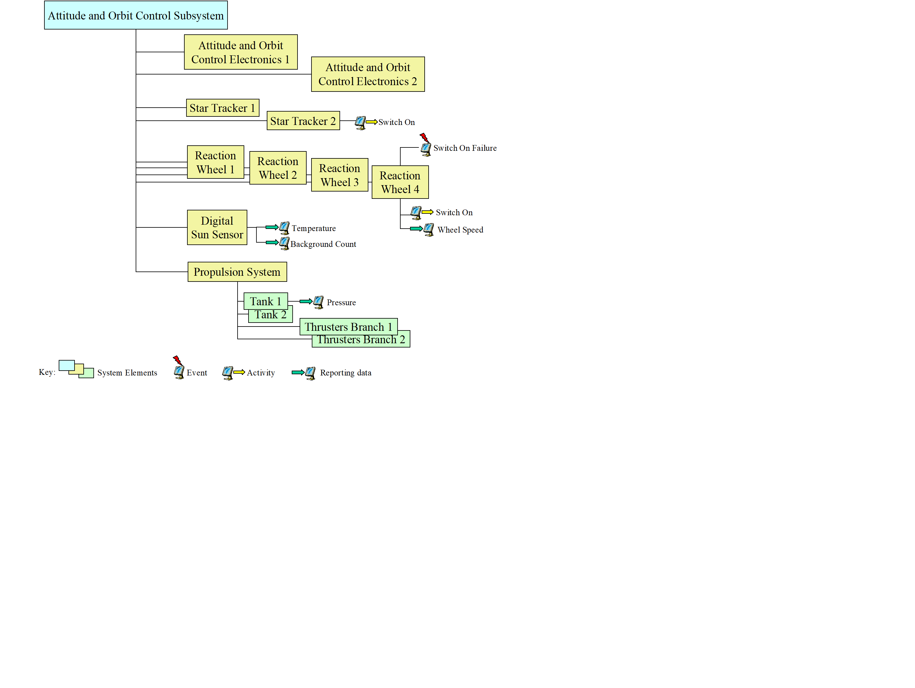 Figure 41: Example product delivery system element hierarchy
Monitoring and control view of the SSM
Introduction
According to the utilisation of the product, actors in different domains will require different “domain-specific views” of the SSM, where a view is the corresponding SE hierarchy (or hierarchies) and the sub-set of SE characteristics relevant to the domain.
The SSM consists of:
“entity” types e.g. system element is an entity type.
“value” types e.g. APID is a value type.
Standard SSM definitions
The SSM types that are relevant for monitoring and control purposes are system elements and their associated activities, reporting data, events and constituent system elements.
An activity is a space system monitoring and control function implemented within the EGSE or mission control system (EMCS). An activity can be implemented as a telecommand either to the space segment or to the ground segment, a procedure, an operating system command (e.g. a printer request, sending an email, transferring a file using FTP) or any other command type that is specific to a given implementation of the space system (e.g. a command to a special check-out system (SCOE) or to a ground station using a proprietary protocol).
Reporting data is information that a system element provides, irrespective of how this information is used. Reporting data can comprise measurements which reflect the state of the associated system element or an output product whose purpose is to be used by another system element (e.g. manoeuvre parameters provided by the flight dynamics system). Reporting data comprises parameters and compound parameters. A parameter is the lowest level of elementary information that has a meaning for monitoring and control of the space system. A compound parameter is a record comprised of any sequence of parameters, arrays of parameters and sub-records (see also ECSSEST-7041). For example, a complete telemetry packet, or part thereof, may be represented as a compound parameter. The parameters within a compound parameter are normally interpreted together (e.g. when interpreting the contents of an anomaly report). Reporting data can have different representations depending on its life cycle within the space system (e.g. an on-board measurement has a raw value in telemetry and an engineering value when presented on a ground segment display).
An event is an occurrence of a condition or group of conditions of operational significance. Events are widely used within the space system to trigger the execution of functions (e.g. acquisition of signal can initiate telemetry processing tasks at the ground station). Users can define mission-specific events, associated with a system element, for example for use within procedures.
In turn, activities, reporting data and events may have their own value and entity types e.g. an activity has a name (value type) and arguments (entity type).
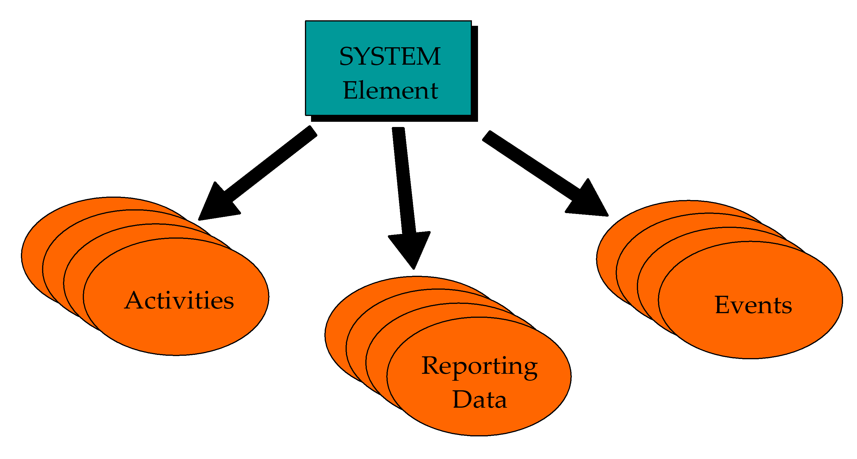 Figure 42: Monitoring and control knowledge associated with a system element
Each actor in the overall space system development life cycle has its own view of the SSM hierarchy, which corresponds to its needs and which is comprised of:
one or more root system elements (a root system element corresponds to a node of the overall SSM hierarchy), and
one or more corresponding system element hierarchies i.e. for each root system element, a view of the decomposition of this system element which is limited in scope to its level of interest.
E.g.: a payload manufacturer only knows about the hierarchy of system elements that correspond to its payload and its EGSE.
The concepts of system elements and their characteristics introduced above enable a complete, high-level description of the space system model independent of any specific space system configuration and, as such, can be reused at any level of integration, test and mission operations. For example, the name and description of an activity always remain the same, although it may be implemented as a simulated command during testing and a procedure during mission operations.
Product-specific SSM tailoring
A tailoring process is required to define the SSM that corresponds to a given product. This implies selecting the applicable subset of the entity and value types identified in this Standard and adding product-specific additional types.
- 1 E.g.: adding types corresponding to a 1553 bus-specific protocol.
- 2 E.g.: tailoring of standard PUS (packet utilization standard, ECSSEST-7041) services for a mission and adding mission-specific services and extensions to the standard PUS services.
- 3 E.g.: Accommodating an existing proprietary protocol for monitoring and controlling an antenna frontend controller.
Conventions
Data definition
This Standard defines the SSM data model (consisting of entity types and value types) that a supplier uses to provide the monitoring and control data for a delivered product.
The SSM data model is specified as a set of requirements in a tabular form. Each table corresponds to an entity type which is uniquely identified by the name of the table.
Tables are comprised of three columns (see Table 51 for an example):
Each row corresponds to a value type.
The first column identifies a value type by means of a name that is unique within the context of the current table.
The second column contains the definition of the type i.e. a description and any applicable constraints.
The third column identifies the data type of the type.
Where the arity of a value type (or a set of value types) is greater than one, the first column also specifies the corresponding lower-level entity type i.e. an ordered list (“Ordered list of…”) or an unordered list (“List of…”).
- 1 Where a condition is expressed for the provision of a given type, the corollary is that the type is NOT provided if the condition is not TRUE.
- 2 Enumerated values and keywords are shown in bold in the tables.
Table 51 Example data requirement table
|
Name
|
Definition
|
Data Type
| |
|
Type
|
The type of array.
|
Enumerated
| |
|
Minimum Number of Repetitions
|
The minimum number of repetitions of the array component
|
Unsigned Integer
| |
|
Maximum Number of Repetitions
|
The maximum number of repetitions of the array component
|
Unsigned Integer
| |
|
Ordered list of
|
Reporting Data
|
The reporting data that comprises the component
|
Reporting Data Reference
|
Within this Standard, a reference to the SSM indicates both the data model as defined by the data requirements and the corresponding mission data provided by a supplier to a customer. The term “SSM object” is used to refer to any object of the populated database that is uniquely identified by a name e.g. a system element, a reporting data, an activity or an event.
Railroad diagrams
A graphical convention is used to define the syntax of language-based data type constructs within the remainder of this Standard. This convention is known as a “railroad” diagram, so-called because of the similarity to a railway network. An example railroad diagram is shown in Figure 51. The elements of this graphical convention are as follows:
the name at the top of the diagram is that of the item being defined, also referred to as a "non-terminal symbol";
a non-terminal symbol is a combination of zero or more non-terminal symbols and "terminal symbols", where a terminal symbol is a sequence of one or more characters forming an irreducible element (i.e. it cannot be decomposed further);
non-terminal symbols are enclosed in rectangles;
terminal symbols are enclosed in round-cornered boxes (in the limit, a circle);
the main line corresponds to mandatory elements of the data type or construct;
branch lines correspond to optional elements;
“return” lines correspond to optional repetitions of one or more elements.
 Figure 51: Example railroad diagram
Figure 51 defines that an integer constant starts with an optional sign followed by one or more digits, followed by optional engineering units.
The “?” is a special-sequence-symbol which indicates the start and end of a special sequence (see ISO/IEC 14977); in this case a standalone syntax for Engineering Units.
Case sensitivity
All words used in expressing the data requirements in this Standard are case-insensitive.
Names
As a result of the distributed approach employed for space system development, the uniqueness of names assigned by a given supplier cannot be guaranteed at a higher-level of integration. For this reason, this Standard introduces the concepts of relative names and reference paths.
A relative name is a name which is unique within a local context. When the context changes and that uniqueness is compromised, the relative name is rendered unique by attaching a reference path.
A relative name is an identifier comprised of one or more identifier words separated by spaces. An identifier word is a sequence of letters (in upper or lower case) and digits.
E.g.: Star Tracker
A reference path is also a name comprised of one or more identifier words separated by spaces. A reference path itself can be comprised of a relative name, unique within a lower-level context, and a reference path rendering it unique. The keyword "of" is used to separate the left-hand part of the name (i.e. the relative name) from the right-hand part of the name (i.e. the reference path).
E.g.: X Thruster of Branch 1
For entities that are associated with a parent entity (e.g. reporting data are associated with system elements, activity arguments are associated with activities) the uniqueness of the name can be achieved in two ways: either by assigning a name that is unique at the level of the child entity (e.g. a reporting data) or by using the parent entity in a reference path.
- 1 E.g.: XGyro temperature
- 2 E.g.: temperature of XGyro
There are no constraints in the use of the keyword "of" in naming entities, except the need to maintain the uniqueness of names with a given product. This implies, for example, that “Temperature of XGyro” can either represent an absolute name of a reporting data or a relative name of a reporting data using “of XGyro” as the reference path.
The syntax for defining names is the following:


 where:
Letter is an upper-case or lower-case letter of the alphabet.
Digit is one of the decimal characters from 0 to 9.
Identifiers are case-insensitive.
Entity Type includes one of “system element”, “activity”, “reporting data”, “parameter” or “event”. The naming convention defined in this clause 5.4 is also used within this Standard to uniquely identify entity types, value types and data types within the SSM data model. This facilitates direct references from supplied data to elements of the SSM data model, e.g. reference to a data type when declaring variables in a test procedure script. For this purpose, Entity Type also includes any entity type referenced within the SSM data model.
Examples of SSM data model names are:
“System Element” which uniquely identifies an entity type within the data model.
“Severity of Event” which uniquely identifies the value type “Severity” of the entity type “Event”.
“Data Type of current parameter” which uniquely identifies the data type of the parameter in whose context it is defined.
Data types
General
The data types used within this Standard are classified as “simple” or “complex”.
The “simple” types include:
the conventional types "Boolean", "integer", "unsigned integer", "real", "bit string", "octet string", "character string", "absolute time" and "relative time";
the types for packet fields identified in ECSSEST-7041 (the PUS) by the parameter code "PC" comprising the parameter type code "PTC" and the parameter format code "PFC". These PUS types correspond to conventional types, however their representation and scope is constrained by the associated PFC definition (e.g. the type PTC 1 PFC 0 corresponds to Boolean, with the characteristic that TRUE = 1 and FALSE = 0);
the enumerated types either defined within this Standard and identified by the keyword “Enumerated”, or user-defined using the “user-defined enumerated type” construct specified in clause 5.5.2.3. An enumerated type is defined by a set of values that can either be:
“absolute” i.e. this Standard identifies all values. Such enumerated sets are indicated with “The set of values is {"a", "b", "c"}”, or
“extensible” i.e. a system compliant with this Standard can add implementation-specific values. Such enumerated sets are indicated with “The set of values includes {"a", "b", "c"}”, or
“mission-specific” i.e. the enumerated set is comprised of mission-specific data;
an enumerated set comprising all populated values (or a subset of these values) of a given data item. Since a data item corresponds to a value type of an SSM object, these types are called “value type sets”;
a data type which is inherited from a data item which is itself a data type. These types are called “value type data types”.
A “complex” type is identified by the name of a language and is defined by the language grammar. Data items of complex type are assigned a character string value whose syntax complies with the language grammar.
Simple Data Types
Conventional data types
Boolean
This type comprises the set of truth values, which can be involved in logical operations.
The syntax used for referring to the Boolean type is the following:
 The syntax for defining constants of type Boolean is the following:

Integer
This type comprises a subset of whole numbers which can be involved in arithmetical, relational and comparative expressions.
The minimum and maximum values are mission-dependent.
The type can have associated engineering units. The engineering units supported by the ECSS-E-ST-70 series of standards are specified in Annex B of ECSSEST-7032
The syntax used for referring to the integer type is the following:
 The syntax for defining constants of type integer is the following:
 where:
Sign is one of the character symbols “+” or “-“.
Digit is one of the decimal characters from 0 to 9 and ?Engineering Units? is one of the engineering units defined in Annex B of ECSSEST-7032.
When providing data of type “integer with associated engineering units”, the value is expressed together with its corresponding units.
E.g.: 23, 2056, 5 A (i.e. 5 amps), 65536 B (i.e. 65536 bytes)
Unsigned Integer
This type comprises a subset of whole positive numbers which can be involved in arithmetical, relational and comparative expressions.
The minimum value is 0 and the maximum value is mission-dependent.
The type can have associated engineering units.
When providing data of type unsigned integer, the value can be given in decimal or in hexadecimal.
The syntax used for referring to the unsigned integer type is the following:
 The syntax for defining constants of type unsigned integer is the following:
 where:
Digit is one of the decimal characters from 0 to 9.
Hexadecimal Constant is a Hexadecimal Symbol followed by one or more Hexadecimal Digits.
Hexadecimal Symbol is the character pair symbol "0x".
Hexadecimal Digit is a decimal character from 0 to 9 or a letter from A to F.
E.g.: 2056, 0x2056, 0xFFFF
When providing data of type “unsigned integer with associated engineering units”, the value is expressed together with its corresponding units.
Real
This type comprises a set of numbers that can be represented with a floating point notation and which can be involved in arithmetical, relational and comparative expressions.
The minimum and the maximum values and the precision are mission-dependent.
The syntax used for referring to the real type is the following:
 The syntax for defining constants of type real is the following:

E.g.: 123, 56e12, 0.1, 23E6
When providing data of type real with associated engineering units, the value is expressed together with its corresponding units.
Bit String
This type comprises a sequence of binary characters i.e. “1”s and “0”s.
The syntax used for referring to the bit string type is the following:
 The syntax for defining constants of type bit string is the following:
 where:
Binary Symbol is the character pair symbol "0b".
Binary Digit is a binary character i.e. 0 or 1.
E.g.: 0b11001
Octet String
This type comprises a sequence of octets, each octet being an ordered sequence of eight bits.
The syntax used for referring to the octet string type is the following:
 The syntax for defining constants of type octet string is the following:
 where:
Hexadecimal Symbol is the character pair symbol "0x".
Hexadecimal Digit is a decimal character from 0 to 9 or a letter from A to F.
E.g.: 0x12AB
Character String
This type comprises any visible character string composed of allowable characters. Character strings can be involved in comparative expressions.
The syntax used for referring to the character string type is the following:
 The syntax for defining constants of type character string is the following:
 where Characters is any sequence of letters or digits or one of the following characters:
space ! " # $ % & ' ( ) * + , - . / :
; < = > ? @ [ \ ] ^ _ ` { | } ~
- 1 E.g.: "This is a string."
- 2 In order to enter a double-quote character (") or a reverse solidus (backslash) character (), a reverse solidus is used as an “escape” character i.e. (") or (\).
Absolute Time
This type comprises a set of values that represents an absolute date which can be involved in arithmetical, relational and comparative expressions.
The syntax used for referring to the absolute time type is the following:
 The syntax for defining constants of type absolute time conforms to the following rule:
 Month/day of month calendar variation
Year-Month-Day Of MonthTHour:Minute:Second.Fraction Of Second(Z)
where:
Year = four digits with a value in the range 0001-9999;
Month = two digits with a value in the range 01-12;
Day Of Month = two digits with a value in the range 01-28, 01-29, 01-30, or 01-31;
"T" = calendar-time separator;
Hour = two digits with a value in the range 00-23;
Minute = two digits with a value in the range 00-59;
Second = two digits with a value in the range 00-59 (00-58 or 00-60 during leap seconds);
Fraction Of Second = one to n digits. To obtain a given precision, the appropriate number of digits to the right of the period is used;
"Z" = optional terminator.
E.g.: 2001-08-18T21:07:43.137468Z
Year/day of year calendar variation
Year-DayTHour:Minute:Second.Fraction Of Second(Z)
where:
Year, "T", Hour, Minute, Second, Fraction Of Second, "Z": are as defined in a. above;
Day = three digits with a value in the range 001-365 or 001-366.
- 1 E.g.: 2001-033T13:21:32.226
- 2 Leading zeros are included to make up the specified number of digits.
- 3 Elements shown in brackets are optional.
Relative Time
This type comprises a set of values that represents an interval of time which can be involved in arithmetical, relational and comparative expressions.
The syntax used for referring to the relative time type is the following:
 The syntax for defining constants of type relative time conforms to the following rule:
 where:
Days, Hours, Minutes and Seconds are unsigned integers;
Hour, Minute, Second and Fraction Of Second are as defined in 5.5.2.1.8 above.
- 1 E.g.: 30 h 10 min
- 2 E.g.: 200 s
- 3 E.g.: -0:00:10:00
PUS Data Types
Service data types
PUS packets defined within ECSSEST-7041 are associated with services and each packet is assigned a “Service Type” and a “Service Subtype”.
The syntax used to refer to the service type data type is the following:
![]() The syntax for defining constants of type service type is:
The syntax for defining constants of type service type is:
![]() The standard service types are defined in ECSSEST-7041 and lie in the range 0 to 127. Mission-specific service types can be defined and lie in the range 128 to 255.
The standard service types are defined in ECSSEST-7041 and lie in the range 0 to 127. Mission-specific service types can be defined and lie in the range 128 to 255.
The syntax used to refer to the service subtype data type is the following:
![]() The syntax for defining constants of type service subtype is:
The syntax for defining constants of type service subtype is:
![]() The standard service subtypes for a given service are defined in ECSSEST-7041 and lie in the range 0 to 127. Mission-specific service subtypes can be defined for standard services and lie in the range 128 to 255 or in the range 0 to 255 for mission-specific services.
The standard service subtypes for a given service are defined in ECSSEST-7041 and lie in the range 0 to 127. Mission-specific service subtypes can be defined for standard services and lie in the range 128 to 255 or in the range 0 to 255 for mission-specific services.
Parameter data types
Data within PUS packets are encoded according to a “Parameter Code (PC)” which is a combination of a “Parameter Type Code (PTC)” and a “Parameter Format Code (PFC)”. The PTC identifies the data type (e.g. Boolean, Integer). The PFC identifies the encoding format and hence constrains the values that the data may take.
The standard PUS data types are defined within ECSSEST-7041 and are as shown in Table 52:
Table 52 PUS data types
|
PTC
|
Data Type
|
PFC
|
|
PTC 1
|
Boolean
|
PFC 0
|
|
PTC 2
|
Enumerated
|
PFC 1 to PFC 16, PFC 24, PFC 32
|
|
PTC 3
|
Unsigned integer
|
PFC 0 to PFC 16
|
|
PTC 4
|
Signed integer
|
PFC 0 to PFC 16
|
|
PTC 5
|
Real
|
PFC 1 to PFC 4
|
|
PTC 6
|
Bit-string
|
PFC 0 to PFC any
|
|
PTC 7
|
Octet-string
|
PFC 0 to PFC any
|
|
PTC 8
|
Character-string
|
PFC 0 to PFC any
|
|
PTC 9
|
Absolute time
|
PFC 0 to PFC 18
|
|
PTC 10
|
Relative time
|
PFC 0 to PFC 16
|
|
PTC 11
|
Deduced
|
PFC 0
|
- 1 Within ECSSEST-7041, the PFC is used to define the size of the encoded value in a packet. In this Standard, the PFC is used to express the possible range of values. For example, PTC 3 PFC 0 implies an integer value between 0 and 15. PTC 8 PFC 12 implies a fixed-length character string of 12 characters length.
- 2 When a Boolean value is used within a telecommand or a telemetry packet, the raw value 0 is used to express a false value, 1 is used to express a truth value.
Within this Standard, three derived data types are used, depending on whether the data type corresponds to the complete Parameter Code or to only a sub-set of the Parameter Code i.e. the PTC alone or the PFC alone.
The syntax used for referring to these data types is one of the following:
![]()
![]()
![]() The syntax for defining constants of type PC depends on the corresponding PTC and PFC values:
The syntax for defining constants of type PC depends on the corresponding PTC and PFC values:
PTC 1, PTC 2 and PTC 3 constants are unsigned integers as specified in clause 5.5.2.1.3.
PTC 4 constants are integers as specified in clause 5.5.2.1.2.
PTC 5 constants are reals as specified in clause 5.5.2.1.4.
PTC 6 constants are Binary Constants consisting of a Binary Symbol (the character pair symbol "0b") followed by one or more Binary Digits (0 or 1).
PTC 7 constants are hexadecimal constants as specified in clause 5.5.2.1.3.
PTC 8 constants are character strings as specified in clause 5.5.2.1.7.
PTC 9 constants are absolute times as specified in clause 5.5.2.1.8.
PTC 10 constants are relative times as specified in clause 5.5.2.1.9.
In each case, if the PFC is specified, the range of possible values is constrained in accordance with ECSSEST-7041.
PTC 11 is not used in this Standard because all parameters of deduced type are instantiated to one of the other PUS data types identified above.
The syntax for defining constants of type PTC is:
![]() The syntax for defining constants of type PFC is:
The syntax for defining constants of type PFC is:
![]()
User-defined enumerated types
As introduced in clause 5.5.1, enumerated sets can be specified by end-users. These enumerated sets are simple data types that can be used when specifying, for example, activity arguments (see clause 6.7.1.2) and parameters (see clause 6.6.3.1).
For each user-defined enumerated type, the data specified in Table 53 shall be provided.
Table 53 User defined enumerated type data
|
Name
|
Definition
|
Data Type
| |
|
Name
|
The name of the enumerated set
|
Name
| |
|
List of
|
Value
|
A value of the enumerated set
|
Character String
|
When the data items associated with these types correspond to parameters whose values are sampled within packets, the raw representation of a given value in the packet can differ from the textual representation given in Table 53.
In the case specified in 5.5.2.3.2a the correspondence between the textual representation and its raw representation shall be defined for each element of the set, as follows.
- When the enumerated set is used for decoding values within telemetry packets which have a one-to-one correspondence between their raw and textual representations or for encoding telecommand arguments within telecommand packets, the data in Table 54 shall be provided for each element of the set. Table 54 Raw correspondence data
|
Name
|
Definition
|
Data Type
|
|
Raw Value
|
The raw value of the set element.
|
PTC 2
|
E.g.: the Battery Charge Status enumerated set is comprised of a list of 3 elements, each one having a raw and textual representation as follows:
|
Value
|
Raw Value
|
|
"trickle charge" |
0 |
|
"full charge" |
1 |
|
"discharge" |
2 |
- When the enumerated set is used for decoding values within telemetry packets or for encoding telecommand arguments within telecommand packets and where there is a many-to-one correspondence between raw and textual representations:
- For each user-defined enumerated type with a many-to-one correspondence between raw and textual representations, the additional data specified in Table 55 shall be provided.
Table 55 Raw data type data
- For each user-defined enumerated type with a many-to-one correspondence between raw and textual representations, the additional data specified in Table 55 shall be provided.
|
Name
|
Definition
|
Data Type
|
|
PTC
|
The PTC of the raw data type.
|
PTC
|
* For each element of the set, the data specified in Table 56 shall be provided.
Table 56 Raw correspondence data
|
Name
|
Definition
|
Data Type
| |
|
List of Raw Value Intervals
|
Minimum Raw Value
|
The raw value of the low boundary of the raw value interval of the set element
|
PTC of Raw Data Type
|
|
Maximum Raw Value
|
The raw value of the upper boundary of the raw interval of the set element
|
PTC of Raw Data Type
| |
E.g.: the position readout of a telescope filter wheel could be interpreted as follows:
|
Value
|
Minimum Raw Value
|
Maximum Raw Value
|
Default Raw Value
| ||
|
"non-operational"
|
0
|
4
|
0
| ||
|
13
|
15
| ||||
|
"red"
|
5
|
6
|
5
| ||
|
"green"
|
7
|
8
|
7
| ||
|
"blue"
|
9
|
10
|
9
| ||
|
"UV"
|
11
|
12
|
11
| ||
- When an enumerated set is used for encoding telecommand arguments within telecommand packets and where there is a many-to-one correspondence between raw and textual representations, the additional data specified in Table 57 shall be provided: Table 57 Telecommand argument encoding data
|
Name
|
Definition
|
Data Type
|
|
Default Raw Value
|
The default value to be used for the argument encoding
|
PTC of Raw Data Type
|
The syntax used for referring to user-defined enumerated types is the following:
![]() where User Defined Enumerated Type Reference is a name of a user-defined enumerated type as specified in 5.5.2.3.1.
where User Defined Enumerated Type Reference is a name of a user-defined enumerated type as specified in 5.5.2.3.1.
Value Type Set
When a data item is of data type “the enumerated set comprising all populated values (or a subset of these values) of another data item”, this data type is of type value type set. The syntax used for referring to a value type set is the following:
 where:
Value Type is an Identifier corresponding to a value type of the SSM data model.
Entity Type is an Identifier corresponding to an entity type of the SSM data model.
Entity Type Reference is one of {"System Element Reference", "Reporting Data Reference", "Activity Reference", "Event Reference", "Activity Argument Reference"}. The value that a corresponding data item can take is one of the names associated with the specified entity type.
- 1 E.g.: the enumerated set identified by “Name of Output Line of current system element”. This set comprises all output line names defined for the current CPDU as specified in Table 669, data item “Name of Output Line”.
- 2 E.g.: the enumerated set identified by “ID of system element of Type "application process"”. This set comprises all application process IDs defined for the mission as specified in Table 614, data item “ID”.
- 3 E.g.: the enumerated set identified by “Name of reporting data of Power Subsystem of Cluster1”. This set comprises all names of reporting data as specified in Table 673, data item “Name”, restricted to those belonging to the Power Subsystem system element of the Cluster 1 system element.
- 4 E.g.: the enumerated set identified by “system element reference of Type "application process"”. This set comprises all names of application processes as specified in Table 68, data item “Name”.
Value Type Data Type
When the type of a data item is inherited from a data item which is itself a data type, this type is of type value type data type. The syntax used for referring to a value type data type is the following:

E.g.: the data type of the data item Engineering Value of linear interpolation data of reporting data as specified in Table 678 is “same as Data Type of current parameter”.
Complex Data Types
A complex data type is identified by the name of a language and defined by a grammar. Data items of complex type are assigned a character string value whose syntax complies with the corresponding language grammar. Within this Standard, the following complex data types are used:
"Activity Call" to define an instantiation of an activity,
"EXPL" to define expressions,
"IFL" to define interpretation functions,
"PLUTO" to define procedures,
"SPEL" to define synthetic parameters,
"VAL" to define values.
Monitoring and control data requirements
Data exchange
This Standard specifies which data shall be delivered by a supplier for the purposes of monitoring and control of the delivered product(s). According to the nature of the product, the product data schema corresponds to:
a subset of the data model identified in this Standard, supplemented by
product-specific entity and value types.
The product data schema to be used for exchange of data shall be specified.
The product data schema shall be suitable for communication, interpretation and processing by computers.
Formal languages are used within this Standard for the definition of data types and constants. Data delivered by suppliers to customers at any point in the overall space system development and operation lifecycle should comply with these languages. Such compliance is encouraged to optimize the process of sharing and reuse of product data.
If other languages are used, these languages shall be formally specified using the extended Backus-Naur form (EBNF), see ISO/IEC 14977.
The product data schema shall ensure the integrity of the data, i.e. it shall be possible to re-import data, extracted in accordance with the schema, without any loss of information.
The electronic database used to transfer the product data shall be subject to configuration management.
The configuration identification data for the electronic database specified in Table 61 shall be provided.
Table 61 Electronic database configuration identification data
|
Name |
Definition |
Data Type |
|
|
ID
|
The Configuration Item (CI) identifier of the electronic database.
|
Enumerated
| |
|
Version Number
|
The version number of the electronic database
|
Name
| |
|
Date
|
The date of generation
|
Absolute Time
| |
|
ID of Supplier
|
The supplier identifier
|
Enumerated
| |
|
List of Digital Files
|
Name
|
The name of a digital file within the electronic database
|
Name
|
|
Type
|
The type of the digital file.
|
Enumerated
| |
|
Type of Checksum
|
The type of the checksum.
|
Enumerated
| |
|
Value of Checksum
|
The checksum of the file
|
Unsigned Integer
| |
Furthermore, the following requirements apply to any constituting digital file.
- Each digital file shall be uniquely identified.
- Each digital file shall be compressed using a standard compression tool (e.g. zip, tar).
Specification of complex data types
General
It shall be possible to include comments at any location in the script of a complex data type.
Activity call
It shall be possible to define the data relating to the instantiation of an activity namely, the activity reference, the values of the activity argument or a reference to a predefined set of argument values and any directives that apply for the instantiation of the activity.
- 1 E.g.: to define corrective actions to be taken in specific circumstances (limit violations, activity failures etc.).
- 2 E.g.: to define arguments of activities (e.g. a PUS service 11 subtype 4 request which inserts telecommand packets in the on-board schedule).
- 3 E.g.: telecommand directives can include for example: the MAP ID to be used; whether the telecommand is to be sent in AD or BD mode; the specification of the telecommand verification packets to be generated in response to this telecommand.
The syntax for defining data of type Activity Call should conform to that specified in Annex A 3.9.28 of ECSSEST-7032
Expression
It shall be possible to specify data values by means of an expression.
E.g.: validity or selection conditions for reporting data or pre-conditions and post-conditions for an activity.
Expressions shall be able to operate on constants and space system parameters acquired from the EMCS.
Mathematical, time and string functions shall be supported.
Engineering units shall be supported.
The capability to assign engineering units to constants shall be supported.
The capability to mix compatible units freely within an expression shall be supported
The automatic conversion between different, but compatible, units shall be supported.
The syntax for defining data of type EXPL should conform to that specified in Annex B.5.
Interpretation function
It shall be possible to specify the interpretation function for a reporting data by means of an expression.
Interpretation function expressions shall be able to operate on constants and space system parameters acquired from the EMCS.
Mathematical, time and string functions shall be supported.
Engineering units shall be supported.
The capability to assign engineering units to constants shall be supported.
The capability to mix compatible units freely within an expression shall be supported.
The automatic conversion between different, but compatible, units shall be supported.
The syntax for defining data of type IFL should conform to that specified in Annex B.6.
Procedure
The requirements in ECSSEST-7032 clause 5 shall apply.
Synthetic parameter
It shall be possible to synthesize reporting data within the EMCS from other reporting data and constants.
It shall be possible to synthesize a parameter or one or more components of a compound parameter.
The evaluation function shall return the engineering value of the synthetic parameter i.e. no subsequent interpretation (e.g. calibration) shall be required.
It shall be possible to specify the condition(s) under which a new value of a synthetic parameter is evaluated (i.e. triggered).
The possible conditions shall include:
- upon update of any reporting data (usually a “contributing” reporting data i.e. one whose value itself is used in the synthetic parameter evaluation).
Update, in this context, means the arrival of a new occurrence of the reporting data, not a change of value of the reporting data.
- upon the occurrence of a specified event;
- any combination of the above.
It shall be possible to define the context in which a synthetic parameter is evaluated i.e. a system element or reporting data context.
The capability shall be provided to perform the following execution flow controls within a synthetic parameter evaluation: - simple conditional branching (i.e. if … then … else …);
- multiple conditional branching where the path taken is dependent on the value of a specified parameter (or local variable, see h below);
Local variables used within a synthetic parameter evaluation shall be declared and their type explicitly stated.
The capability shall be provided to assign a value to a local variable.
Persistent variables shall be supported. - 1 A persistent variable is one whose value is maintained (memorized) from one evaluation of a synthetic parameter to the next.
- 2 E.g.: a synthetic parameter that uses the delta between the current value and the previous value of a given parameter.
It shall be possible to define an expression when assigning a value to a local variable or to a synthetic parameter.
Synthetic parameter expressions shall be able to operate on constants, space system parameters acquired from the EMCS and local variables.
Mathematical, time and string functions shall be supported.
Engineering units shall be supported.
The capability to assign engineering units to constants shall be supported.
The capability to mix compatible units freely within an expression shall be supported
The automatic conversion between different, but compatible, units shall be supported.
The syntax for defining data of type SPEL should conform to that specified in Annex B.7.
Value set
It shall be possible to specify fixed values or value sets for data items.
E.g.: default values.
It shall be possible to specify a simple value, a record value or an array value for a single value or a component of a value set.
The syntax for defining data of type VAL should conform to that specified in Annex B.9.
Product data
Introduction
Product data corresponds to the data that is provided, together with a given product delivery, by a supplier to a customer and comprises:
Product configuration data;
Product monitoring and control data (i.e. the SSM).
Product configuration data
Overview
According to ECSS-M-ST-40, product configuration data is provided to enable traceability from a product to its defining documentation.
Depending on the configuration management requirements associated with a given product, different types of product configuration data are provided.
Requirement
For each product identified within the electronic database, the data specified in Table 62 shall be provided.
Table 62 Product configuration data
|
Name
|
Definition
|
Data Type
|
|
Name of Product
|
The name of the product which is unique within this delivery
|
Name
|
|
Nature
|
The nature of the product.
|
Enumerated
|
|
Type
|
The type of product.
|
Enumerated
|
For products of type “developed hardware CI”, the additional data specified in Table 63 shall be provided.
Table 63 Developed hardware CI configuration data
|
Name
|
Definition
|
Data Type
|
|
ID
|
The Configuration Item identifier
|
Enumerated
|
|
Part Number
|
The part number of the product
|
Character String
|
|
Serial Number
|
The serial number of the product
|
Character String
|
|
Number
|
The lot number of the product
|
Character String
|
|
Model
|
The model of the space system to which the product is applicable e.g. EM, STM, FM
|
Enumerated
|
|
ID of Manufacturer
|
The identifier of the manufacturer (i.e. the original supplier)
|
Enumerated
|
For products of type “developed software CI”, the additional data specified in Table 64 shall be provided.
Table 64 Developed software CI configuration data
|
Name
|
Definition
|
Data Type
|
|
ID
|
The Configuration Item identifier
|
Enumerated
|
|
Software Identifier
|
The identifier of the software
|
Enumerated
|
|
Version Number
|
The version number of the software
|
Name
|
|
Release Date
|
The date of release of this version of the software
|
Absolute Time
|
|
ID of Manufacturer
|
The identifier of the manufacturer (i.e. the original supplier)
|
Enumerated
|
For products of type “COTS and standard product”, the additional data specified in Table 65 shall be provided.
Table 65 COTS and standard product configuration data
|
Name
|
Definition
|
Data Type
|
|
Part Number
|
The part number of the product
|
Character String
|
|
Serial Number
|
The serial number of the product
|
Character String
|
|
Number
|
The lot number of the product
|
Character String
|
|
ID of Manufacturer
|
The identifier of the manufacturer (i.e. the original supplier)
|
Enumerated
|
For products of type “non CI product” (i.e. not defined as a configuration item), the additional data specified in Table 66 shall be provided.
Table 66 Non CI product configuration data
|
Name
|
Definition
|
Data Type
|
|
Part Number
|
The part number of the product
|
Character String
|
|
Serial Number
|
The serial number of the product
|
Character String
|
|
Number
|
The lot number of the product
|
Character String
|
|
ID of Manufacturer
|
The identifier of the manufacturer (i.e. the original supplier)
|
Enumerated
|
When one (or more) property of a system element has changed between successive deliveries of the same product or when one (or more) activities, reporting data, events or constituent system elements has been created or deleted, a new version shall be defined for this system element.
When one (or more) property of an activity has changed between successive product deliveries, a new version shall be defined for this activity.
When one (or more) property of a reporting data has changed between successive product deliveries or when one (or more) sub reporting data of a reporting data (i.e. of record type) has been created or deleted, a new version shall be defined for this reporting data.
When one (or more) property of an event has changed between successive product deliveries, a new version shall be defined for this event.’
The SSM corresponds to one or more elements of the overall space system.
The product configuration data also contains configuration data for each constituent system element, activity, reporting data and event of the SSM according to the previous requirements.
For each system element, activity, reporting data and event of the SSM, the data specified in Table 67 shall be provided.
Table 67 Version data
|
Data
|
Definition
|
Data Type
|
|
Number
|
The version number of the configuration data
|
Name
|
|
Date
|
The date when this configuration item version was produced
|
Absolute Time
|
|
Originator
|
The name of the organization or person responsible of having produced this configuration item version
|
Character String
|
|
Reason
|
The reason(s) for the change, with respect to the previous version
|
Character String
|
|
Status
|
Information relating to the validation testing status of this configuration item.
|
Enumerated
|
The data specified in Table 62, Table 63, Table 64, Table 65 or Table 66 shall be provided for each constituent product, according to the product type.
The data specified in Table 67 shall be provided for each object (i.e. system elements, reporting data, activities and events) of the SSM associated with each constituent product.
Products are the result of procurement and integration activities at lower-levels and earlier phases in the overall space system lifecycle.
The objective of these requirements is to allow the traceability of information supplied at these lower-levels (or earlier phases).
Data population
All monitoring and control data shall be provided using the English language.
All monitoring and control data shall be considered as case-insensitive, with the exception of engineering units.
Engineering units are defined in Annex B of ECSSEST-7032.
If the name of an SSM object (i.e. system elements, reporting data, activities or events) is changed during integration of lower-level products, the former name(s) of this object shall be retained within the integrated product for traceability purposes.
The data supplied with the delivered product shall be fully consistent with the product documentation (e.g. ICD, user manual).
Uniqueness of SSM objects names within a given product delivery shall be ensured.
Some elements of the space system are qualified for a maximum number of operational cycles or a maximum operational life. For these elements, the accumulated number of operational cycles or the accumulated operational life shall be provided with each product delivery.
Sufficient information shall be provided by the sub-suppliers such that the data required by the customer is fully populated.
Data specific to a domain (e.g. Software, AIV or Operations) shall be identified as such.
The principal customers of the monitoring and control data are “Software” (i.e. on-board and ground software development teams), “AIV” and “Operations”.
Data required to monitor and control the space system in all operational and testing modes shall be fully populated.
For the SSM, fully populated shall mean:
- All system elements that correspond to the delivered product be provided.
- All monitoring and control characteristics of the system elements are provided. In the case of ECSSEST-7041 services (and other on-board software), this includes all service configuration data required on ground for monitoring and control of the service. For reporting data, fully populated means:
- All reporting data defined within the product documentation shall be provided. This includes all data that can be downlinked, for example, software tables and memory dumps.
- When more than one reporting data conveys the same information, the redundancy link between them shall be provided.
- All interpretation functions (required to calibrate raw values) shall be provided together with the conditions under which they are applied.
- When the validity of a reporting data depends on specific conditions, the validity conditions shall be provided.
- Ground monitoring checks shall be provided for all reporting data together with the conditions under which they are applied.
The only exceptions are reporting data that can take any possible value.
- When the value that a reporting data may take depends on the execution of a given activity or the occurrence of a given event, status consistency checks shall be provided accordingly.
- The corrective actions to be taken whenever a reporting data violates a given check shall be provided. For activities, fully populated means:
- All activities defined within the product documentation (e.g. operation procedures contained in the space segment user manual) shall be provided.
- All atomic activities used to control elements of the space system shall be provided.
- Arguments of activities shall be provided in engineering values together with (where applicable) the deinterpretation function used to produce the raw values.
- Pre-conditions and post-conditions for activities shall be provided.
- When the start, progress and completion of execution of activities can be deduced from low-level reporting data, the corresponding verification conditions shall be provided (regardless of whether the ECSSEST-7041 telecommand verification service is used).
- When activities are “redundant” i.e. they have the same effect, the redundancy link between these activities shall be provided.
- When activities have the opposite effect, the reverse link between these activities shall be provided.
- The criticality level of each activity shall be provided (e.g. non-critical, mission-critical).
- The corrective actions to be taken whenever the start, progress and completion of execution of an activity are unsuccessful shall be provided.
- The execution profile of activities (i.e. expected duration, minimum and maximum duration) shall be provided.
- The resources utilised during the execution of an activity shall be provided. For events, fully populated means:
- All events defined within the product documentation shall be provided.
- The corrective actions to be taken whenever an event occurs shall be provided. All data contained within the product delivery shall be validated (e.g. by review, by test with simulators, by test with real hardware).
Some data, such as descriptions, can only be validated by review.
For operational use, all data shall be validated with real hardware wherever possible.
The exceptions are those activities that cannot be executed on ground for safety or environmental reasons.
System element data
Introduction
From the monitoring and control viewpoint there is data that is generic to all system elements and data that is specific to the type of the system element. This Standard identifies a number of specialised types, for example application process, service and multiplexed access point (MAP).
System element generic data
For each system element associated with a product or a sub-product, the data specified in Table 68 shall be provided.
Table 68 System element data
|
Name
|
Definition
|
Data Type
| |
|
Name
|
The name of the system element which is unique within the context of the product
|
Name
| |
|
Description
|
The description of the system element
|
Character String
| |
|
Type
|
The type of the system element.
|
Enumerated
| |
|
Nature
|
The nature of the definition.
|
Enumerated
| |
|
List of References
|
Name of Product
|
The name of a sub-product that has been integrated in the current product (see clause 6.3.2)
|
Product Reference
|
|
Name of System Element
|
The name of the system element within the sub-product
|
System Element Reference
| |
|
List of
|
Name of Redundant System Element
|
A system element that is redundant with the system element i.e. has the identical function and is provided for the purposes of increasing the availability of the function
|
System Element Reference
|
For system elements which can be the source of telecommand packets or the destination of telemetry packets, the data specified in Table 69 shall be provided.
Table 69 Packet address data
|
Name
|
Definition
|
Data Type
|
|
ID
|
The unique identifier of the source or destination as defined in
|
PTC 2
|
For system elements which have limitation on their number of operation cycles and/or duration, the operation control data specified in Table 610 shall be provided.
Table 610 Operation control data
|
Name
|
Definition
|
Data Type
| |
|
Maximum Cycles
|
The maximum number of operational cycles permitted for this system element
|
Unsigned Integer
| |
|
Maximum Duration
|
The maximum cumulative operational life permitted for this system element
|
Relative Time
| |
|
List of Operations
|
Date
|
A date on which the system element has been operated
|
Absolute Time
|
|
Duration
|
The duration of the corresponding operation
|
Relative Time
| |
|
Cumulative Cycles
|
The accumulated number of operational cycles for this system element
|
Unsigned Integer
| |
|
Cumulative Duration
|
The accumulated operational life for this system element
|
Relative Time
| |
System data
General
For system elements of type “system”, the additional data specified in Table 611 shall be provided.
Table 611 System data
|
Name
|
Definition
|
Data Type
|
|
ID
|
The unique identifier of the system
|
PTC 2
|
|
Type
|
The type of the system.
|
Enumerated
|
Telecommand packet tailoring data
For system elements of type “system” that utilise ECSSEST-7041, the additional data specified in Table 612 shall be provided.
Table 612 System level telecommand packet tailoring data
|
Name
|
Definition
|
Data Type
| ||
|
To be provided where the packet data field contains a Source ID field
| ||||
|
|
PFC of Source ID
|
The PFC of the Source ID field in the packet data field header
|
PFC of PTC 2
| |
|
List of
|
Source
|
A possible telecommand source
|
System Element Reference
| |
|
Presence of CPDU DFH
|
The definition of whether or not a data field header is used for CPDU telecommands
|
Boolean
| ||
|
Maximum Length of TC Packet
|
The maximum length of a telecommand packet
|
Unsigned Integer with units B
| ||
Telemetry packet tailoring data
For system elements of type “system” that utilise ECSSEST-7041, the additional data specified in Table 613 shall be provided for tailoring of telemetry packets.
Table 613 System level telemetry packet tailoring data
|
Name
|
Definition
|
Data Type
| ||
|
To be provided where the packet data field contains a Destination ID field
| ||||
|
|
PFC of Destination ID
|
The PFC of the Destination ID field in the packet data field header
|
PFC of PTC 2
| |
|
List of
|
Destination
|
A possible destination
|
System Element Reference
| |
|
Presence of Spacecraft Time Source Packet DFH
|
The definition of whether or not a data field header is used for the “spacecraft time source packet”.
|
Boolean
| ||
|
Maximum Length of TM Packet
|
The maximum length of a telemetry packet
|
Unsigned Integer with units B
| ||
Application process data
General
For system elements of type “application process”, the additional data specified in Table 614 shall be provided.
Table 614 Application process data
|
Name
|
Definition
|
Data Type
| ||
|
ID
|
The identifier of the application process (APID) which is unique within a system element of type system
|
PTC 2
| ||
|
List of Service Accesses
|
Type
|
The type of the service access to other system elements.
|
Enumerated
| |
|
List of
|
Name of System Element
|
A system element accessible for this service access type
|
System Element Reference
| |
|
Word Length
|
The word length used by the application process, where spare bits are used to pad the data field header and the overall packet length to be an integral number of words.
|
Enumerated
| ||
|
PFC of Variable Bit String
|
The PFC used for the length field of variable-length bit-string parameters (PTC 6)
|
PFC of PTC 3
| ||
|
PFC of Variable Octet String
|
The PFC used for the length field of variable-length octet-string parameters (PTC 7)
|
PFC of PTC 3
| ||
|
PFC of Variable Character String
|
The PFC used for the length field of variable-length character-string parameters (PTC 8)
|
PFC of PTC 3
| ||
Telecommand packet tailoring data
For system elements of type “application process”, the additional data specified in Table 615 shall be provided.
Table 615 Application process level telecommand packet tailoring data
|
Name
|
Definition
|
Data Type
|
|
Type of TC Checksum
|
The type of the checksum.
|
Enumerated
|
Telemetry packet tailoring data
For system elements of type “application process”, the additional data specified in Table 616 shall be provided.
Table 616 Application process level telemetry packet tailoring data
|
Name
|
Definition
|
Data Type
| |
|
To be provided where the packet data field contains a Time Field
| |||
|
|
PFC of Time Field
|
The PFC of the Time Field
|
PFC of PTC 9
|
|
Packet Subcounter
|
Whether or not there is a packet sub-counter for this application process
|
Boolean
| |
|
Type of TM Checksum
|
The type of checksum used for checking the integrity of telemetry packets from the application process.
|
Enumerated
| |
Service data
Introduction
Application processes are the entities that provide services. This Standard assumes that application processes and services are also used within the ground segment. Therefore, to this extent, the ground segment and the space segment are modelled within the SSM in an analogous manner.
The data to be provided for each standard ECSSEST-7041 service in the rest of this clause 6.5.5 is structured as follows:
The specification of how the service has been tailored for the mission is provided in the form of a set of tailoring variables. The need to provide specific additional service data depends strongly on how the service has been tailored for a given mission. Annex A contains, for each service, its tailoring algorithm expressed in the form of a flowchart showing the successive tailoring choices available for the service and the tailoring variables associated with these choices. The presence of a given tailoring variable may depend on the decision path taken through this flowchart. This conditionality is also expressed in the tailoring variable tables in this clause 6.5.5.
The data types of the different fields of the service requests (telecommand packets) and service reports (telemetry packets). Again, depending on the tailoring choices made, some of the fields shown in ECSSEST-7041 may not be present. Annex A shows the standard ECSSEST-7041 packet structures and any conditionality associated with them.
The service-specific configuration data i.e. the data required by the ground to model the ECSSEST-7041 service for monitoring and control purposes.
Service data is defined separately for each distinct application process.
Telecommand verification service
Tailoring data
For the definition of the tailoring of the telecommand verification service, the additional data shown in Table 617 shall be provided.
Table 617 Telecommand verification service tailoring data
|
Name
|
Definition
|
Data Type
|
|
S1 ST3 and ST4 Provider |
Whether this service verifies start of telecommand execution |
Boolean |
|
S1 ST5 and ST6 Provider |
Whether this service verifies progress of telecommand execution |
Boolean |
|
S1 ST7 and ST8 Provider |
Whether this service verifies completion of telecommand execution. |
Boolean |
Packet field data types data
For the data types of the packet fields of the telecommand verification service, the additional data shown in Table 618 shall be provided.
Table 618 Telecommand verification service data types data
|
Name
|
Definition
|
Data Type
| |
|
S1 Code
|
The PFC of the Code fields
|
PFC of PTC 2
| |
|
To be provided if S1 ST5 and ST6 Provider = TRUE
| |||
|
|
S1 Step Number
|
The PFC of the Step Number fields
|
PFC of PTC 2
|
Service data
For the telecommand verification service, the additional data specified in Table 619 shall be provided (see clause 6.7.4.9 for related command execution check data).
Table 619 Telecommand verification service data
|
Name
|
Definition
|
Data Type
| ||
|
List of Command Failures
|
Name
|
The name of a specific command verification failure applicable to all commands
|
Name
| |
|
Code
|
The corresponding failure code value.
|
PTC 2
| ||
|
Applicability
|
The stage(s) to which the command failure code is applicable.
|
Enumerated
| ||
|
Description
|
The description of the command failure
|
Character String
| ||
|
Ordered list of
|
Component
|
A component of the parameters field associated with the code value
|
Reporting Data Reference
| |
Device command distribution service
Tailoring data
For the definition of the tailoring of the device command distribution service, the additional data shown in Table 620 shall be provided.
Table 620 Device command distribution service tailoring data
|
Name
|
Definition
|
Data Type
| ||
|
S2 ST3 Provider |
Whether this service distributes CPDU commands |
Boolean |
||
|
To be provided if S2 ST3 Provider = FALSE |
||||
|
|
S2 ST1 Provider |
Whether this service distributes On/Off commands |
Boolean |
|
|
To be provided if S2 ST1 Provider = TRUE |
||||
|
|
S2 Multiple OnOff Distribution |
Whether this service can distribute multiple On/Off commands in a single telecommand |
Boolean |
|
|
S2 ST2 Provider |
Whether this service distributes Register Load commands |
Boolean |
||
|
To be provided if S2 ST2 Provider = TRUEa |
||||
|
|
S2 Multiple Register Load Distribution |
Whether this service can distribute multiple Register Load commands in a single telecommand |
Boolean |
|
|
aS2 ST2 Provider = TRUE if S2 ST3 Provider = FALSE AND S2 ST1 Provider = FALSE |
||||
Packet field data types data
For the data types of the packet fields of the device command distribution service, the additional data shown in Table 621 shall be provided.
Table 621 Device command distribution service data types data
|
Name
|
Definition
|
Data Type
| |
|
To be provided if S2 Multiple OnOff Distribution = FALSE OR S2 Multiple Register Load Distribution = FALSE |
|||
|
|
S2 N |
The PFC of the number of repetitions fields |
PFC of PTC 3 |
|
To be provided if S2 ST1 Provider = TRUE |
|||
|
|
S2 OnOff Address |
The PFC of the On/Off Address fields |
PFC of PTC 2 |
|
To be provided if S2 ST2 Provider = TRUE |
|||
|
|
S2 Register Load Address |
The PFC of the Register Load Address fields |
PFC of PTC 2 |
See clauses 6.5.12, 6.5.13 and 6.5.14 for the related CPDU, On/Off and register load device data.
Service data
There is no additional service-specific data for the device command distribution service.
Housekeeping and diagnostic data reporting service
Tailoring data
For the definition of the tailoring of the housekeeping and diagnostic data reporting service, the additional data shown in Table 622 shall be provided.
Table 622 Housekeeping and diagnostic data reporting service tailoring data
|
Name
|
Definition
|
Data Type
| |||||
|
S3 HK Provider |
Whether this service reports housekeeping data |
Boolean |
|||||
|
To be provided if S3 HK Provider = TRUE |
|||||||
|
|
S3 ST1 ST3 ST5 and ST6 Provider |
Whether control of housekeeping reports is provided |
Boolean |
||||
|
To be provided if S3 ST1 ST3 ST5 and ST6 Provider = TRUE |
|||||||
|
|
S3 HK Implicit Collection Interval |
Whether an implicit housekeeping packet collection interval is used |
Boolean |
||||
|
S3 HK Multiple Clear SID |
Whether multiple housekeeping reporting definitions can be cleared |
Boolean |
|||||
|
S3 HK Multiple Control SID |
Whether multiple housekeeping reporting definitions can be controlled |
Boolean |
|||||
|
S3 ST9 and ST10 Provider |
Whether this service can report housekeeping parameter definitions |
Boolean |
|||||
|
To be provided if S3 ST9 and ST10 Provider = TRUE |
|||||||
|
|
S3 HK Multiple Report SID |
Whether this service can report multiple housekeeping parameter definitions |
Boolean |
||||
|
S3 ST13 and ST15 Provider |
Whether this service can report housekeeping parameter sampling time offsets |
Boolean |
|||||
|
S3 ST17 and ST19 Provider |
Whether this service supports housekeeping filtered mode |
Boolean |
|||||
|
To be provided if S3 ST17 and ST19 Provider = TRUE |
|||||||
|
|
S3 HK Default Timeout |
Whether a housekeeping default timeout is used |
Boolean |
||||
|
S3 HK Default Threshold |
Whether a housekeeping default threshold is used |
Boolean |
|||||
|
S3 HK Default Threshold Type |
Whether a housekeeping default threshold type is used |
Boolean |
|||||
|
S3 HK Filtered Parameters |
Whether filtering of housekeeping parameters is supported |
Boolean |
|||||
|
To be provided if S3 HK Filtered Parameters = TRUE |
|||||||
|
|
S3 HK Implicit Filter |
Whether there is implicit knowledge of which housekeeping parameters are filtered |
Boolean |
||||
|
To be provided if S3 HK Implicit Filter = FALSE |
|||||||
|
|
S3 ST21 and ST23 Provider |
Whether the unfiltered housekeeping parameters can be reported |
Boolean |
||||
|
S3 Diagnostic Provider |
Whether this service reports diagnostic data |
Boolean |
|||||
|
To be provided if S3 Diagnostic Provider = TRUE |
|||||||
|
|
S3 Diagnostic Implicit Collection Interval |
Whether an implicit diagnostic packet collection interval is used |
Boolean |
||||
|
S3 Diagnostic Multiple Clear SID |
Whether multiple diagnostic reporting definitions can be cleared |
Boolean |
|||||
|
S3 Diagnostic Multiple Control SID |
Whether multiple diagnostic reporting definitions can be controlled |
Boolean |
|||||
|
S3 ST11 and ST12 Provider |
Whether this service can report diagnostic parameter definitions |
Boolean |
|||||
|
To be provided if S3 ST11 and ST12 Provider = TRUE |
|||||||
|
|
S3 Diagnostic Multiple Report SID |
Whether this service can report multiple diagnostic parameter definitions |
Boolean |
||||
|
S3 ST14 and ST16 Provider |
Whether this service can report diagnostic parameter sampling time offsets |
Boolean |
|||||
|
S3 ST18 and ST20 Provider |
Whether this service supports diagnostic filtered mode |
Boolean |
|||||
|
To be provided if S3 ST18 and ST20 Provider = TRUE |
|||||||
|
|
S3 Diagnostic Default Timeout |
Whether a diagnostic default timeout is used |
Boolean |
||||
|
S3 Diagnostic Default Threshold |
Whether a diagnostic default threshold is used |
Boolean |
|||||
|
S3 Diagnostic Default Threshold Type |
Whether a diagnostic default threshold type is used |
Boolean |
|||||
|
S3 Diagnostic Filtered Parameters |
Whether filtering of diagnostic parameters is supported |
Boolean |
|||||
|
To be provided if S3 Diagnostic Filtered Parameters = TRUE |
|||||||
|
|
S3 Diagnostic Implicit Filter |
Whether there is implicit knowledge of which diagnostic parameters are filtered |
Boolean |
||||
|
To be provided if S3 Diagnostic Implicit Filter = FALSE |
|||||||
|
|
S3 ST22 and ST24 Provider |
Whether the unfiltered diagnostic parameters can be reported |
Boolean |
||||
Packet field data types data
For the data types of the packet fields of the housekeeping and diagnostic data reporting service, the additional data shown in Table 623 shall be provided.
Table 623 Housekeeping and diagnostic data reporting service data types data
|
Name
|
Definition
|
Data Type
| |
|
S3 SID
|
The PFC of the report identifier field
|
PFC of PTC 2
| |
|
To be provided if S3 HK Implicit Collection Interval = TRUE OR S3 Diagnostic Implicit Collection Interval= TRUE
| |||
|
|
S3 Collection Interval
|
The PFC of the Collection Interval field
|
PFC of PTC 3
|
|
To be provided if S3 ST1 ST3 ST5 and ST6 Provider = TRUE OR S3 ST9 and ST10 Provider = TRUE OR S3 Diagnostic Provider = TRUE
| |||
|
|
S3 NPAR1
|
The PFC of the number of repetitions field for parameters
|
PFC of PTC 3
|
|
S3 NFA
|
The PFC of the number of repetitions field for supercommutated parameter definitions
|
PFC of PTC 3
| |
|
S3 NREP
|
The PFC of the number of parameter repetitions field
|
PFC of PTC 3
| |
|
S3 NPAR2
|
The PFC of the number of repetitions field for parameters
|
PFC of PTC 3
| |
|
To be provided if S3 ST1 ST3 ST5 and ST6 Provider = TRUE OR S3 ST9 and ST10 Provider = TRUE OR S3 ST13 and ST15 Provider = TRUE OR S3 ST17 and ST19 Provider = TRUE OR S3 Diagnostic Provider = TRUE
| |||
|
|
S3 Parameter Number
|
The PFC of the Parameter# field
|
PFC of PTC 2
|
|
To be provided if S3 HK Multiple Clear SID = TRUE OR S3 HK Multiple Control SID = TRUE OR S3 HK Multiple Report SID = TRUE OR S3 Diagnostic Multiple Clear SID = TRUE OR S3 Diagnostic Multiple Control SID = TRUE OR S3 Diagnostic Multiple Report SID
| |||
|
|
S3 NSID
|
The PFC of the number of repetitions field for report identifiers
|
PFC of PTC 3
|
|
To be provided if S3 ST13 and ST15 Provider = TRUE OR S3 ST14 and ST16 Provider = TRUE
| |||
|
|
S3 Time Offset
|
The PFC of the Time Offset field
|
PFC of PTC 10
|
|
To be provided if S3 HK Default Timeout = TRUE OR S3 Diagnostic Default Timeout = TRUE
| |||
|
|
S3 Timeout
|
The PFC of the Timeout field
|
PFC of PTC 3
|
|
To be provided if (S3 HK Filtered Parameters = TRUE AND S3 HK Implicit Filter =FALSE) OR (S3 Diagnostic Filtered Parameters = TRUE AND S3 Diagnostic Implicit Filter = FALSE)
| |||
|
|
S3 N
|
The PFC of the number of repetitions field for parameter threshold definitions
|
PFC of PTC 3
|
|
To be provided if S3 HK Default Threshold Type = FALSE OR S3 Diagnostic Default Threshold Type = FALSE
| |||
|
|
S3 Threshold Type
|
The PFC of the Threshold Type field
|
PFC of PTC 2
|
|
To be provided if S3 HK Default Threshold =FALSE OR S3 Diagnostic Default Threshold =FALSE
| |||
|
|
S3 Threshold
|
The PFC of the Threshold field
|
PFC of PTC 3
|
|
To be provided if S3 ST17 and ST19 Provider = TRUE OR S3 ST18 and ST20 Provider = TRUE
| |||
|
|
S3 Mode
|
The PFC of the Mode field
|
PFC of PTC 3
|
Service data
For the housekeeping and diagnostic data reporting service, the additional data specified in Table 624 shall be provided.
Table 624 Housekeeping and diagnostic data reporting service data
|
Name
|
Definition
|
Data Type
| |
|
Minimum Sampling Interval
|
The minimum sampling interval at which parameters can be sampled on-board in diagnostic mode. This sampling interval is used as a time unit for the specification of several other time parameters e.g. the collection interval for a housekeeping or diagnostic report.
|
Relative Time
| |
|
Absolute Sampling Accuracy
|
The accuracy with which the absolute on-board sampling of parameters is known.
|
Relative Time
| |
|
Relative Sampling Accuracy
|
The accuracy with which the relative on-board sampling of parameters is known.
|
Relative Time
| |
|
To be provided if S3 HK Implicit Collection Interval = TRUE
| |||
|
|
Default HK Collection Interval
|
The default value for the collection interval for housekeeping report packets
|
Relative Time
|
|
To be provided if S3 HK Default Timeout = TRUE
| |||
|
|
Default HK Timeout
|
The default value for the timeout for the generation of a one-shot housekeeping packet when the packets are being generated in filtered mode
|
Relative Time
|
|
To be provided if S3 HK Default Threshold Type = TRUE
| |||
|
|
Type of Default HK Threshold
|
The default value for the type of threshold used for filtering parameter values when packets are being generated in filtered mode.
|
Enumerated
|
|
To be provided if S3 HK Default Threshold = TRUE
| |||
|
|
Value of Default HK Threshold
|
The default value for the threshold used for filtering parameter values when packets are being generated in filtered mode
|
Unsigned Integer
|
|
To be provided if S3 Diagnostic Implicit Collection Interval = TRUE
| |||
|
|
Default Diagnostic Collection Interval
|
The default value for the collection interval for diagnostic report packets
|
Relative Time
|
|
To be provided if S3 Diagnostic Default Timeout = TRUE
| |||
|
|
Default Diagnostic Timeout
|
The default value for the timeout for the generation of a one-shot diagnostic packet when the packets are being generated in filtered mode
|
Relative Time
|
|
To be provided if S3 Diagnostic Default Threshold Type = TRUE
| |||
|
|
Type of Default Diagnostic Threshold
|
The default value for the type of threshold used for filtering parameter values when packets are being generated in filtered mode.
|
Enumerated
|
|
To be provided if S3 Diagnostic Default Threshold = TRUE
| |||
|
|
Value of Default Diagnostic Threshold
|
The default value for the threshold used for filtering parameter values when packets are being generated in filtered mode
|
Unsigned Integer
|
SID data
For each reporting data that represents a housekeeping report, the additional data specified in Table 625 shall be provided.
Table 625 Housekeeping report definition data
|
Name
|
Definition
|
Data Type
| |||
|
SID
|
The unique identifier of the housekeeping report within the service
|
PTC 2
| |||
|
Ordered list of Components
|
Reporting Data
|
A reporting data component of this SID
|
Reporting Data Reference
| ||
|
Time Offset
|
The time offset of the sampling time of the reporting data from the packet time
|
Relative Time
| |||
|
Predefined Onboard
|
The definition of whether the corresponding reporting data definition is predefined on-board
|
Boolean
| |||
|
To be provided if S3 HK Implicit Collection Interval = FALSE
| |||||
|
|
Collection Interval
|
The interval of time used for collecting the parameters contained in this report
|
PTC 3
| ||
|
To be provided if S3 HK Implicit Filter = TRUE
| |||||
|
|
List of
|
Parameter
|
A filtered parameter when this report is generated in filtered mode
|
Reporting Data Reference
| |
For each reporting data that represents a diagnostic report, the additional data specified in Table 626 shall be provided.
Table 626 Diagnostic report definition data
|
Name
|
Definition
|
Data Type
| |||
|
SID
|
The unique identifier of the diagnostic report within the service
|
PTC 2
| |||
|
Ordered list of Components
|
Reporting Data
|
A reporting data component of this SID
|
Reporting Data Reference
| ||
|
Time Offset
|
The time offset of the sampling time of the reporting data from the packet time
|
Relative Time
| |||
|
Predefined Onboard
|
The definition of whether the corresponding reporting data definition is predefined on-board
|
Boolean
| |||
|
To be provided if S3 Diagnostic Implicit Collection Interval = FALSE
| |||||
|
|
Collection Interval
|
The interval of time used for collecting the parameters contained in this report
|
PTC 3
| ||
|
To be provided if S3 Diagnostic Implicit Filter = TRUE
| |||||
|
|
List of
|
Parameter
|
A filtered parameter when this report is generated in filtered mode
|
Reporting Data Reference
| |
Parameter statistics reporting service
Tailoring data
For the definition of the tailoring of the parameter statistics reporting service, the additional data shown in Table 627 shall be provided.
Table 627 Parameter statistics reporting service tailoring data
|
Name
|
Definition
|
Data Type
| ||
|
S4 ST4 and ST5 Provider |
Whether the concept of periodic reporting is supported |
Boolean |
||
|
To be provided if S4 ST4 and ST5 Provider = TRUE |
||||
|
|
S4 Default Reporting Interval |
Whether a default value is used for the reporting interval |
Boolean |
|
|
S4 Add Parameters |
Whether parameters can be added to the reporting list |
Boolean |
||
|
To be provided if S4 Add Parameters = TRUE |
||||
|
|
S4 Default Sampling Interval |
Whether a default value is used for the parameter sampling interval |
Boolean |
|
|
S4 Multiple Parameters |
Whether multiple parameters can be loaded at once |
Boolean |
||
|
S4 ST6 and ST7 Provider |
Whether parameters can be deleted from the reporting list |
Boolean |
||
|
To be provided if S4 ST6 and ST7 Provider = TRUE |
||||
|
|
S4 ST6 and ST10 Providera |
Whether the reporting list can be cleared |
Boolean |
|
|
S4 ST8 and ST9 Provider |
Whether the parameter statistics list can be reported |
Boolean |
||
|
S4 Always Reset |
Whether the evaluation of parameter statistics is always reset |
Boolean |
||
|
S4 Standard Deviation |
Whether the standard deviation of parameters can be evaluated |
Boolean |
||
|
aS4 ST6 and ST10 Provider is always TRUE if S4 Add Parameters = TRUE AND S4 ST6 and ST7 Provider = FALSE |
||||
Packet field data types data
For the data types of the packet fields of the parameter statistics reporting service, the additional data shown in Table 628 shall be provided.
Table 628 Parameter statistics reporting service data types data
|
Name
|
Definition
|
Data Type
| |
|
To be provided if S4 Always Reset = FALSE
| |||
|
|
S4 Reset Flag
|
The PFC of the Reset Flag field
|
PFC of PTC 2
|
|
S4 Time
|
The PFC of the Time fields
|
PFC of PTC 9
| |
|
S4 NPAR
|
The PFC of the number of repetitions field for parameters
|
PFC of PTC 3
| |
|
S4 Parameter Number
|
The PFC of the Parameter# field
|
PFC of PTC 2
| |
|
To be provided if S4 Default Reporting Interval = FALSE OR S4 Default Sampling Interval = FALSE
| |||
|
|
S4 Relative Time
|
The PFC of the Relative Time fields
|
PFC of PTC 10
|
Service data
For the parameter statistics reporting service, the additional data specified in Table 629 shall be provided.
Table 629 Parameter statistics reporting service data
|
Name
|
Definition
|
Data Type
| |
|
Maximum Parameters
|
The maximum number of parameters whose statistical results can be evaluated at a given time.
|
Unsigned Integer
| |
|
To be provided if S4 Default Reporting Interval = TRUE
| |||
|
|
Default Reporting Interval
|
The default value for the periodic reporting interval for the parameter statistics results
|
Relative Time
|
|
To be provided if S4 Default Sampling Interval = TRUE
| |||
|
|
Default Sampling Interval
|
The default value for the sampling interval for all parameters in the list
|
Relative Time
|
Event reporting service
Tailoring data
For the definition of the tailoring of the parameter statistics reporting service, the additional data shown in Table 630 shall be provided.
Table 630 Event reporting service tailoring data
|
Name
|
Definition
|
Data Type
| |
|
S5 ST5 and ST6 Provider |
Whether event reports can be enabled and disabled |
Boolean |
|
|
To be provided if S5 ST5 and ST6 Provider = TRUE |
|||
|
|
S5 Multiple RIDs |
Whether multiple event reports can be enabled and disabled |
Boolean |
Packet field data types data
For the data types of the packet fields of the event reporting service, the additional data shown in Table 631 shall be provided.
Table 631 Event reporting service data types data
|
Name
|
Definition
|
Data Type
| |
|
S5 RID
|
The PFC of the report identifier field
|
PFC of PTC 2
| |
|
To be provided if S5 Multiple RIDs = TRUE
| |||
|
|
S5 NRID
|
The PFC of the number of repetitions field for report identifiers
|
PFC of PTC 3
|
On-board event data
For each event raised by this service, the additional data specified in Table 632 shall be provided.
Table 632 Event data
|
Name
|
Definition
|
Data Type
|
|
RID
|
The unique identifier of the corresponding event report
|
PTC 2
|
Memory management service
Tailoring data
For the definition of the tailoring of the memory management service, the additional data shown in Table 633 shall be provided.
Table 633 Memory management service tailoring data
|
Name
|
Definition
|
Data Type
| ||
|
S6 ST1 ST3 and ST4 Provider |
Whether a managed memory uses the base plus offset addressing technique |
Boolean |
||
|
To be provided if S6 ST1 ST3 and ST4 Provider = TRUE |
||||
|
|
S6 Symbolic Base References |
Whether symbolic base references are supported |
Boolean |
|
|
S6 Base Multiple Memory Blocks |
Whether multiple memory blocks are supported |
Boolean |
||
|
S6 Base Data Level Checksum |
Whether checksums at data level are supported |
Boolean |
||
|
S6 Base Scatter Load |
Whether scatter loading is supported |
Boolean |
||
|
S6 Base Scatter Dump |
Whether scatter dumping is supported |
Boolean |
||
|
S6 ST7 and ST8 Provider |
Whether on-board checking of memory is supported |
Boolean |
||
|
To be provided if S6 ST7 and ST8 Provider = TRUE |
||||
|
|
S6 Base Scatter Check |
Whether scatter checking is supported |
Boolean |
|
|
S6 ST2 ST5 and ST6 Provider |
Whether a managed memory uses the absolute addressing technique |
Boolean |
||
|
To be provided if S6 ST2 ST5 and ST6 Provider = TRUEa |
||||
|
|
S6 Absolute Multiple Memory Blocks |
Whether multiple memory blocks are supported |
Boolean |
|
|
S6 Absolute Data Level Checksum |
Whether checksums at data level are supported |
Boolean |
||
|
S6 Absolute Scatter Load |
Whether scatter loading is supported |
Boolean |
||
|
S6 Absolute Scatter Dump |
Whether scatter dumping is supported |
Boolean |
||
|
S6 ST9 and ST10 Provider |
Whether on-board checking of memory is supported |
Boolean |
||
|
To be provided if S6 ST9 and ST10 Provider = TRUE |
||||
|
|
S6 Absolute Scatter Check |
Whether scatter checking is supported |
Boolean |
|
|
aS6 ST2 ST5 and ST6 Provider is always TRUE if S6 ST1 ST3 and ST4 Provider = FALSE |
||||
Packet field data types data
For the data types of the packet fields of the memory management service, the additional data shown in Table 634 shall be provided.
Table 634 Memory management service data types data
|
Name
|
Definition
|
Data Type
| |
|
To be provided if S6 Base Multiple Memory Blocks = TRUE OR S6 Absolute Multiple Memory Blocks = TRUE |
|||
|
|
S6 Memory ID |
The PFC of the Memory Identifier field |
PFC of PTC 7, PFC > 0 |
|
To be provided if S6 Base Scatter Load = TRUE OR S6 Base Scatter Dump = TRUE OR S6 Base Scatter Check = TRUE OR S6 Absolute Scatter Load = TRUE OR S6 Absolute Scatter Dump = TRUE OR S6 Absolute Scatter Check = TRUE |
|||
|
|
S6 N |
The PFC of the number of repetitions field |
PFC of PTC 3 |
|
To be provided if S6 ST1 ST3 and ST4 Provider = TRUE |
|||
|
|
S6 Offset |
The PFC of the Offset field |
PFC of PTC 4 |
|
S6 Length |
The PFC of the Length field |
PFC of PTC 3 |
|
|
To be provided if S6 ST2 ST5 and ST6 Provider = TRUE |
|||
|
|
S6 Start Address |
The PFC of the Start Address field |
PFC of PTC 3 |
Where a symbolic base reference is used (S6 Symbolic Base References = TRUE), the additional data specified in Table 635 shall be provided.
Table 635 Symbolic base reference data
|
Name
|
Definition
|
Data Type
|
|
S6 Base
|
The PFC of the Symbolic Base Reference field
|
PFC of PTC 8, PFC > 0
|
Where an unsigned integer base is used (S6 Symbolic Base References = FALSE), the additional data specified in Table 636 shall be provided.
Table 636 Unsigned integer base data
|
Name
|
Definition
|
Data Type
|
|
S6 Base
|
The PFC of the Unsigned Integer Base field
|
PFC of PTC 3
|
See clauses 6.5.9 and 6.5.10 for the related memory block and memory sub-block data.
Service data
There is no additional service-specific data for the memory management service.
Function management service
Tailoring data
For the definition of the tailoring of the function management service, the additional data shown in Table 637 shall be provided.
Table 637 Function management service tailoring data
|
Name
|
Definition
|
Data Type
|
|
S8 Parameter Subset |
Whether a sub-set of function parameters can be loaded |
Boolean |
Packet field data types data
For the data types of the packet fields of the function management service, the additional data shown in Table 638 shall be provided.
Table 638 Function management service data types data
|
Name
|
Definition
|
Data Type
| |
|
S8 Function ID
|
The PFC of the Function Identifier field
|
PFC of PTC 8, PFC > 0
| |
|
To be provided if S8 Parameter Subset = TRUE
| |||
|
|
S8 N
|
The PFC of the number of repetitions field for parameters and their values
|
PFC of PTC 3
|
|
S8 Parameter Number
|
The PFC of the Parameter# field
|
PFC of PTC 2
| |
See clause 6.5.8 for the related function definition data.
Service data
There is no additional service-specific data for the function management service.
Time management service
Tailoring data
For the definition of the tailoring of the time management service, the additional data shown in Table 639 shall be provided.
Table 639 Time management service tailoring data
|
Name
|
Definition
|
Data Type
| |
|
S9 ST1 Provider |
Whether this service supports control of the rate of the time packet |
Boolean |
|
|
S9 ST2 Provider |
Whether this service provides the spacecraft time source packet |
Boolean |
|
|
To be provided if S9 ST2 Provider = TRUE |
|||
|
|
S9 Basic Report |
Whether only a basic time reporting service is provided |
Boolean |
Packet field data types data
For the data types of the packet fields of the time management service, the additional data shown in Table 640 shall be provided.
Table 640 Time management service data types data
|
Name
|
Definition
|
Data Type
| ||
|
To be provided if S9 ST2 Provider = TRUE
| ||||
|
|
S9 Satellite Time
|
The PFC of the Satellite Time field
|
PFC of PTC 9
| |
|
To be provided if S9 Basic Report = FALSE
| ||||
|
|
PTC of S9 Status
|
The parameter type code of the Status field (i.e. the PTC of ECSSEST-7041)
|
PTC
| |
|
PFC of S9 Status
|
The parameter format code of the Status field (i.e. the PFC of ECSSEST-7041)
|
PFC of PTC of S9 Status
| ||
Service data
For the time management service, the additional data specified in Table 641 shall be provided.
Table 641 Time management service data
|
Name
|
Definition
|
Data Type
| ||
|
To be provided if this is not contained explicitly in the Satellite Time field
| ||||
|
|
Time Code
|
The value of the P-field for the time report packet (subtype 2).
|
Enumerated
| |
|
To be provided if S9 Basic Report = FALSE
| ||||
|
|
List of Statuses
|
Value
|
A status value identified for the service
|
same as S9 Status
|
|
Description
|
The interpretation of the status
|
Character String
| ||
On-board operations scheduling service
Tailoring data
For the definition of the tailoring of the on-board operations scheduling service, the additional data shown in Table 642 shall be provided.
Table 642 Onboard scheduling service tailoring data
|
Name
|
Definition
|
Data Type
| ||
|
S11 Subschedule Support |
Whether the concept of sub-schedules is supported |
Boolean |
||
|
To be provided if S11 Subschedule Support = TRUE |
||||
|
|
S11 Subschedule Selection |
Whether the concept of selection of telecommands at sub-schedule level is supported |
Boolean |
|
|
S11 Relative Time Support |
Whether the concept of relative time is supported |
Boolean |
||
|
S11 Interlock Support |
Whether the concept of command interlocking is supported |
Boolean |
||
|
S11 Application Selection |
Whether the concept of command selection at Application Process level is supported |
Boolean |
||
|
S11 Multiple Insert |
Whether insertion of multiple commands is supported |
Boolean |
||
|
S11 ST5 Provider |
Whether deletion of commands from the schedule is supported |
Boolean |
||
|
To be provided if S11 ST5 Provider = TRUE |
||||
|
|
S11 ST6 Provider |
Whether deletion of commands over a time period is supported |
Boolean |
|
|
S11 ST15 Provider |
Whether time-shifting of commands in the schedule is supported |
Boolean |
||
|
To be provided if S11 ST15 Provider = TRUE |
||||
|
|
S11 ST7 Provider |
Whether time-shifting of selected commands is supported |
Boolean |
|
|
To be provided if S11 ST7 Provider = TRUE |
||||
|
|
S11 ST8 Provider |
Whether time-shifting of commands over a time period is supported |
Boolean |
|
|
S11 ST16 and ST10 Provider |
Whether reporting of the schedule in detailed form is supported |
Boolean |
||
|
To be provided if S11 ST16 and ST10 Provider = TRUE |
||||
|
|
S11 ST9 Provider |
Whether detailed reporting of selected commands is supported |
Boolean |
|
|
To be provided if S11 ST9 Provider = TRUE |
||||
|
|
S11 ST11 Provider |
Whether detailed reporting over a time period is supported |
Boolean |
|
|
S11 ST17 and ST13 Provider |
Whether reporting of the schedule in summary form is supported |
Boolean |
||
|
To be provided if S11 ST17 and ST13 Provider = TRUE |
||||
|
|
S11 ST12 Provider |
Whether summary reporting of selected commands is supported |
Boolean |
|
|
To be provided if S11 ST12 Provider = TRUE |
||||
|
|
S11 ST14 Provider |
Whether summary reporting over a time period is supported |
Boolean |
|
|
To be provided if S11 ST5 Provider = TRUE OR S11 ST15 Provider = TRUE OR S11 ST16 and ST10 Provider = TRUE |
||||
|
|
S11 Scattering Support |
Whether scatter (delete, time-shifting or detailed reporting) support is provided |
Boolean |
|
|
S11 ST18 and ST19 Provider |
Whether reporting of the status of the schedule is supported |
Boolean |
||
Packet field data types data
For the data types of the packet fields of the on-board operations scheduling service, the additional data shown in Table 643 shall be provided.
Table 643 Onboard operations scheduling service data types data
|
Name
|
Definition
|
Data Type
| |
|
To be provided if S11 Subschedule Support = TRUE
| |||
|
|
S11 N1
|
The PFC of the number of repetitions field for telecommand sets
|
PFC of PTC 3
|
|
S11 Subschedule ID
|
The PFC of the Sub-schedule Identifier field
|
PFC of PTC 2
| |
|
To be provided if S11 Application Selection = TRUE
| |||
|
|
S11 N2
|
The PFC of the number of repetitions field for Application Process Identifiers
|
PFC of PTC 3
|
|
S11 APID
|
The PFC of the Application Process Identifier field
|
PFC of PTC 2
| |
|
To be provided if S11 Multiple Insert = TRUE OR S11 Scattering Support = TRUE
| |||
|
|
S11 N
|
The PFC of the number of repetitions field for telecommands
|
PFC of PTC 3
|
|
To be provided if S11 Interlock Support = TRUE
| |||
|
|
S11 Interlock ID
|
The PFC of the Interlock Identifier field
|
PFC of PTC 2
|
|
S11 Assessment Type
|
The PFC of the Assessment Type field
|
PFC of PTC 2
| |
|
To be provided if S11 Relative Time Support = TRUE
| |||
|
|
S11 Scheduling Event
|
The PFC of the Scheduling Event field
|
PFC of PTC 2
|
|
S11 Relative CUC Time
|
The PFC of relative CUC time fields.
|
PFC of PTC 10
| |
|
To be provided if S11 ST5 Provider = TRUE OR S11 ST7 Provider = TRUE OR S11 ST9 Provider = TRUE
| |||
|
|
S11 Sequence Count
|
The PFC of the Sequence Count field
|
PFC of PTC 3
|
|
S11 Number of TCs
|
The PFC of the Number of Telecommands field
|
PFC of PTC 3
| |
|
To be provided if S11 ST6 Provider = TRUE OR S11 ST8 Provider = TRUE OR S11 ST11 Provider = TRUE
| |||
|
|
S11 Range
|
The PFC of the Range field
|
PFC of PTC 2
|
|
S11 Absolute CUC Time
|
The PFC of absolute CUC time fields
|
PFC of PTC 9
| |
|
To be provided if S11 ST18 and ST 19 Provider = TRUE
| |||
|
|
S11 Status
|
The PFC of the Status field
|
PFC of PTC 2
|
Service data
For the on-board operations scheduling service, the additional data specified in Table 644 shall be provided.
Table 644 Onboard operations scheduling service data
|
Name
|
Definition
|
Data Type
| |
|
Maximum Size of Schedule
|
The maximum size of the buffer allocated for scheduled telecommands
|
Unsigned Integer with units B
| |
|
To be provided if S11 Subschedule Support = TRUE
| |||
|
|
Maximum Number of Subschedules
|
The maximum number of sub-schedules that can be supported
|
Unsigned Integer
|
|
To be provided if S11 Interlock Support = TRUE
| |||
|
|
Maximum Number of Interlocks
|
The maximum number of interlocks (per sub-schedule) that can be supported
|
Unsigned Integer
|
For each event of type “scheduling event”, the additional data specified in Table 645 shall be provided.
Table 645 Scheduling event data
|
Name
|
Definition
|
Data Type
|
|
Name
|
A mission-specific event that can be used as the base to which the relative time of a loaded telecommand is referenced
|
Event Reference
|
|
ID
|
The identifier of the event. The values 0, 1, 2 and 3 are reserved for standard use by the PUS
|
PTC 2
|
On-board monitoring service
Tailoring data
For the definition of the tailoring of the on-board monitoring service, the additional data shown in Table 646 shall be provided.
Table 646 Onboard monitoring service tailoring data
|
Name
|
Definition
|
Data Type
| ||||
|
S12 Multiple Enable and Disable |
Whether multiple parameters can be enabled and disabled |
Boolean |
||||
|
S12 ST3 Provider |
Whether the maximum reporting delay can be changed |
Boolean |
||||
|
S12 ST5 Provider |
Whether parameters can be added to the monitoring list |
Boolean |
||||
|
S12 ST7 Provider |
Whether parameter checking information can be modified |
Boolean |
||||
|
To be provided if S12 ST5 Provider = TRUE |
||||||
|
|
S12 Default Monitoring Interval |
Whether there is a default monitoring interval |
Boolean |
|||
|
S12 ST4 Provider |
Whether the monitoring list can be cleared |
Boolean |
||||
|
To be provided if S12 ST4 Provider = TRUE |
||||||
|
|
S12 ST6 Providera |
Whether parameters can be deleted from the monitoring list |
Boolean |
|||
|
To be provided if S12 ST5 Provider = TRUE OR S12 ST7 Provider = TRUE |
||||||
|
|
S12 ST8 and ST9 Provider |
Whether the current monitoring list can be reported |
Boolean |
|||
|
S12 Multiple Parameters |
Whether multiple parameters can be added, deleted or modified |
Boolean |
||||
|
S12 Parameter Validity Support |
Whether the concept of parameter validity is supported |
Boolean |
||||
|
S12 Event Reports |
Whether event reports can be linked to monitoring violations |
Boolean |
||||
|
S12 Expected Value Check |
Whether expected value checking is supported |
Boolean |
||||
|
To be provided if S12 Expected Value Check = TRUE |
||||||
|
|
To be provided if S12 ST5 Provider = TRUE OR S12 ST8 and ST9 Provider = TRUE |
|||||
|
|
S12 Default Value Repetitions |
Whether there is a default value for the number of successive samples required to establish a new checking status |
Boolean |
|||
|
S12 Multiple Expected Value Checks |
Whether multiple expected value checks can be defined per parameter |
Boolean |
||||
|
S12 Limit Check |
Whether limit checking is supported |
Boolean |
||||
|
To be provided if S12 Limit Check = TRUE |
||||||
|
|
To be provided if S12 Expected Value Check = FALSE AND S12 ST5 Provider = TRUE OR S12 ST8 and ST9 Provider = TRUE |
|||||
|
|
S12 Default Value Repetitions |
Whether there is a default value for the number of successive samples required to establish a new checking status |
Boolean |
|||
|
S12 Multiple Limit Checks |
Whether multiple limit checks can be defined per parameter |
Boolean |
||||
|
To be provided if S12 Expected Value Check = TRUE OR S12 Limit Check = TRUE |
||||||
|
|
S12 Delta Check |
Whether delta checking is supported |
Boolean |
|||
|
To be provided if S12 Delta Check = TRUE |
||||||
|
|
To be provided if S12 ST5 Provider = TRUE OR S12 ST8 and ST9 Provider = TRUE |
|||||
|
|
S12 Default Delta Repetitions |
Whether there is a default value for the number of successive samples required to establish a new checking status |
|
|||
|
S12 Multiple Delta Checks |
Whether multiple delta checks can be defined per parameter |
Boolean |
||||
|
S12 ST10 and ST11 Provider |
Whether the current parameters out-of-limits list can be reported |
Boolean |
||||
|
S12 Transition Time |
Whether transition time is required in the check transition report |
Boolean |
||||
|
aS12 ST6 Provider is always TRUE if S12 ST4 Provider = FALSE |
||||||
Packet field data types data
For the data types of the packet fields of the on-board monitoring service, the additional data shown in Table 647 shall be provided.
Table 647 Onboard monitoring service data types data
|
Name
|
Definition
|
Data Type
| |
|
S12 N
|
The PFC of the number of repetitions field for parameters (and monitoring attributes)
|
PFC of PTC 3
| |
|
S12 Parameter Number
|
The PFC of the Parameter# field
|
PFC of PTC 2
| |
|
To be provided if S12 ST3 Provider = TRUE
| |||
|
|
S12 Maximum Reporting Delay
|
The PFC of the Maximum Reporting Delay field
|
PFC of PTC 3
|
|
To be provided if S12 Default Monitoring Interval = TRUE
| |||
|
|
S12 Parameter Monitoring Interval
|
The PFC of the Parameter Monitoring Interval field
|
PFC of PTC 3
|
|
To be provided if S12 Default Value Repetitions = FALSE OR S12 Default Delta Repetitions =FALSE
| |||
|
|
S12 Repetitions
|
The PFC of the number of repetition fields
|
PFC of PTC 3
|
|
To be provided if S12 Multiple Limit Checks = TRUE
| |||
|
|
S12 NOL
|
The PFC of the number of repetitions field for limit checks
|
PFC of PTC 3
|
|
To be provided if S12 Multiple Delta Checks = TRUE
| |||
|
|
S12 NOD
|
The PFC of the number of repetitions field for delta checks
|
PFC of PTC 3
|
|
To be provided if S12 Multiple Expected Value Checks = TRUE
| |||
|
|
S12 NOE
|
The PFC of the number of repetitions field for expected value checks
|
PFC of PTC 3
|
|
To be provided if S12 Event Reports = TRUE
| |||
|
|
S12 RID
|
The PFC of the report identifier field
|
PFC of PTC 2
|
|
To be provided if S12 ST7 Provider = TRUE AND (S12 Multiple Limit Checks = TRUE OR S12 Multiple Delta Checks = TRUE OR S12 Multiple Expected Value Checks = TRUE)
| |||
|
|
S12 Check Position
|
The PFC of the Check Position field
|
PFC of PTC 4
|
|
To be provided if S12 ST8 and ST9 Provider = TRUE
| |||
|
|
S12 Monitoring Status
|
The PFC of the monitoring status fields
|
PFC of PTC 2
|
|
S12 Checking Status
|
The PFC of the checking status fields
|
PFC of PTC 2
| |
|
To be provided if S12 ST10 and ST11 Provider = TRUE OR S12 Transition Time = TRUE
| |||
|
|
S12 Time
|
The PFC of the Transition Time field
|
PFC of PTC 9
|
Service data
For the on-board monitoring service, the additional data specified in Table 648 shall be provided.
Table 648 Onboard monitoring service data
|
Name
|
Definition
|
Data Type
| |
|
To be provided if S12 ST5 Provider = TRUE
| |||
|
|
Maximum Number of Parameters
|
The maximum number of parameters that can be loaded in the on-board monitoring list.
|
Unsigned Integer
|
|
Maximum Number of Checks
|
The maximum number of checks that can be defined per parameter.
|
Unsigned Integer
| |
|
To be provided if S12 Default Value Repetitions = TRUE
| |||
|
|
Default Number of Limit or Status Transitions
|
The number of successive times that a limit or expected status check transition is registered before a new checking status is declared for the corresponding parameter
|
Unsigned Integer
|
|
To be provided if S12 Default Delta Repetitions = TRUE
| |||
|
|
Default Number of Delta Transitions
|
The number of successive times that a delta check transition is registered before a new checking status is declared for the corresponding parameter
|
Unsigned Integer
|
|
To be provided if S12 Default Monitoring Interval = TRUE
| |||
|
|
Default Monitoring Interval
|
The default value used for the interval between successive samples of parameters for the purposes of the on-board monitoring
|
Relative Time
|
Large data transfer service
Tailoring data
For the definition of the tailoring of the large data transfer service, the additional data shown in Table 649 shall be provided.
Table 649 Large data transfer service tailoring data
|
Name
|
Definition
|
Data Type
| ||
|
S13 Large Downlink Provider |
Whether this service supports the downlink of large data units |
Boolean |
||
|
To be provided if S13 Large Downlink Provider = TRUE |
||||
|
|
S13 Downlink Multiple Data Units |
Whether multiple data units can be downlinked in parallel |
Boolean |
|
|
S13 ST6 and ST7 Provider |
Whether the concept of re-sending lost or erroneous parts is supported |
Boolean |
||
|
To be provided if S13 ST6 and ST7 Provider = TRUE |
||||
|
|
S13 Downlink Sliding Window |
Whether the concept of a sliding window is supported |
Boolean |
|
|
S13 ST4 Reason Code |
Whether the ground requires the use of a Reason Code when the downlink transfer is aborted by the on-board service |
Boolean |
||
|
S13 ST8 Reason Code |
Whether the on-board service can process a Reason Code when the downlink transfer is aborted by the ground |
Boolean |
||
|
S13 Large Uplink Provider |
Whether this service supports the uplink of large data units |
Boolean |
||
|
To be provided if S13 Large Uplink Provider = TRUE |
||||
|
|
S13 Uplink Multiple Data Units |
Whether multiple data units can be uplinked in parallel |
Boolean |
|
|
S13 ST12 and ST15 Provider |
Whether the concept of re-sending lost or erroneous parts is supported |
Boolean |
||
|
To be provided if S13 ST12 and ST15 Provider = TRUE |
||||
|
|
S13 Uplink Sliding Window |
Whether the concept of a sliding window is supported |
Boolean |
|
|
S13 ST13 Reason Code |
Whether the on-board service can process a Reason Code when the uplink transfer is aborted by the ground |
Boolean |
||
|
S13 ST16 Reason Code |
Whether the ground requires the use of a Reason Code when the uplink transfer is aborted by the on-board service |
Boolean |
||
Packet field data types data
For the data types of the packet fields of the large data transfer service, the additional data shown in Table 650 shall be provided.
Table 650 Large data transfer service data types data
|
Name
|
Definition
|
Data Type
| |
|
To be provided if S13 Downlink Multiple Data Units = TRUE OR S13 Uplink Multiple Data Units = TRUE |
|||
|
|
S13 Large Data Unit ID |
The PFC of the Large Data Unit Identifier field |
PFC of PTC 2 |
|
S13 Sequence Number |
The PFC of the Sequence Number field |
PFC of PTC 3 |
|
|
To be provided if S13 ST6 and ST7 Provider = TRUE OR S13 ST12 and ST15 Provider = TRUE |
|||
|
|
S13 N |
The PFC of the number of repetitions field for sequence numbers |
PFC of PTC 3 |
|
To be provided if S13 ST4 Reason Code = TRUE OR S13 ST8 Reason Code = TRUE OR S13 ST13 Reason Code = TRUE OR S13 ST16 Reason Code = TRUE |
|||
|
|
S13 Reason Code |
The PFC of the Reason Code field |
PFC of PTC 2 |
Service data
For a sending sub-service (S13 Large Downlink Provider = TRUE), the additional data specified in Table 651 shall be provided.
Table 651 Large data transfer sending subservice data
|
Name
|
Definition
|
Data Type
| |||
|
Size of Part
|
The size of the parts into which the large service data unit is split. This part size is equal to or smaller than the maximum telemetry source packet size defined for the mission.
|
Unsigned Integer with units B
| |||
|
To be provided if S13 Downlink Sliding Window = TRUE
| |||||
|
|
List of Sliding Windows
|
Size
|
The size of the sliding window expressed as the maximum number of parts that can be in transmission at any given time for which no reception acknowledgement has been received
|
Unsigned Integer
| |
|
Name of System Element
|
The application process or service from which the original large service data unit originates
|
System Element Reference of Type "application process" or System Element Reference of Type "service"
| |||
|
Acknowledgement Timeout Interval
|
The time interval for the acknowledgement timer after which the transfer is aborted if no reception acknowledgement is received from the ground
|
Relative Time
| |||
|
List of Reasons
|
Code
|
A service-wide reason code for aborting the transfer at the receiving end i.e. by the ground
|
PTC 2
| ||
|
Description
|
The interpretation of the reason for aborting
|
Character String
| |||
For a receiving sub-service (S13 Large Uplink Provider = TRUE), the additional data specified in Table 652 shall be provided.
Table 652 Large data transfer receiving subservice data
|
Name
|
Definition
|
Data Type
| |
|
Size of Part
|
The size of the parts into which the large service data unit is split. This part size is equal to or smaller than the maximum telecommand packet size defined for the mission.
|
Unsigned Integer with units B
| |
|
List of Reasons
|
Code
|
A service-wide reason code for aborting the transfer at the receiving end i.e. by the on-board service
|
PTC 2
|
|
Description
|
The interpretation of the reason for aborting
|
Character String
| |
|
Reception Timeout Interval
|
The time interval for the reception timer after which the reception activity is locally aborted if no subsequent parts are received
|
Relative Time
| |
Packet forwarding control service
Tailoring data
For the definition of the tailoring of the packet forwarding control service, the additional data shown in Table 653 shall be provided.
Table 653 Packet forwarding control service tailoring data
|
Name
|
Definition
|
Data Type
| |
|
S14 Centralised |
Whether this is a centralised service |
Boolean |
|
|
S14 ST3 and ST4 Provider |
Whether the list of enabled telemetry packets can be reported |
Boolean |
|
|
S14 ST5 and ST6 Provider |
Whether specified housekeeping packets can be controlled |
Boolean |
|
|
To be provided if S14 ST5 and ST6 Provider = TRUE |
|||
|
|
S14 ST7 and ST8 Provider |
Whether the list of enabled housekeeping packets can be reported |
Boolean |
|
S14 ST9 and ST10 Provider |
Whether specified diagnostic packets can be controlled |
Boolean |
|
|
To be provided if S14 ST9 and ST10 Provider = TRUE |
|||
|
|
S14 ST11 and ST12 Provider |
Whether the list of enabled diagnostic packets can be reported |
Boolean |
|
S14 ST13 and ST14 Provider |
Whether specified event packets can be controlled |
Boolean |
|
|
To be provided if S14 ST13 and ST14 Provider = TRUE |
|||
|
|
S14 ST15 and ST16 Provider |
Whether the list of enabled event packets can be reported |
Boolean |
|
To be provided if S14 ST5 and ST6 Provider = TRUE OR S14 ST9 and ST10 Provider = TRUE OR S14 ST13 and ST14 Provider = TRUE |
|||
|
|
S14 Multiple Packet Control |
Whether multiple packets can be controlled |
Boolean |
Packet field data types data
For the data types of the packet fields of the packet forwarding control service, the additional data shown in Table 654 shall be provided.
Table 654 Packet forwarding control service data types data
|
Name
|
Definition
|
Data Type
| |
|
S14 N
|
The PFC of the number of repetitions fields
|
PFC of PTC 3
| |
|
To be provided if S14 Centralised = TRUE
| |||
|
|
S14 APID
|
The PFC of the Application Process Identifier field
|
PFC of PTC 2
|
|
S14 Type
|
The PFC of the (service) Type and Subtype fields
|
PFC of PTC 2
| |
|
To be provided if S14 ST5 and ST6 Provider = TRUE OR S14 ST9 and ST10 Provider = TRUE
| |||
|
|
S14 SID
|
The PFC of the structure identifier field
|
PFC of PTC 2
|
|
To be provided if S14 ST13 and ST14 Provider = TRUE
| |||
|
|
S14 RID
|
The PFC of the report identifier field
|
PFC of PTC 2
|
Service data
There is no additional service-specific data for the packet forwarding control service.
On-board storage and retrieval service
Tailoring data
For the definition of the tailoring of the on-board storage and retrieval service, the additional data shown in Table 655 shall be provided.
Table 655 Onboard storage and retrieval service tailoring data
|
Name
|
Definition
|
Data Type
| |||||
|
S15 Multiple Packet Store |
Whether multiple packet stores are supported |
Boolean |
|||||
|
S15 Packet Selection Provider |
Whether this service provides a packet selection sub-service |
Boolean |
|||||
|
To be provided if S15 Packet Selection Provider = TRUE |
|||||||
|
|
S15 ST3 and ST4 Provider |
Whether the storage selection definition can be changed |
Boolean |
||||
|
To be provided if S15 ST3 and ST4 Provider = TRUE |
|||||||
|
|
S15 ST5 and ST6 Provider |
Whether the storage selection definition can be reported |
Boolean |
||||
|
S15 Storage and Retrieval Provider |
Whether this service provides a storage and retrieval sub-service |
Boolean |
|||||
|
To be provided if S15 Storage and Retrieval Provider = TRUE |
|||||||
|
|
S15 Centralised |
Whether the service is centralised |
Boolean |
||||
|
To be provided if S15 Storage and Retrieval Provider = TRUEa |
|||||||
|
|
S15 Circular Packet Store |
Whether circular packet stores are supported |
Boolean |
||||
|
To be provided if S15 Circular Packet Store = TRUE AND S15 Multiple Packet Store = TRUE |
|||||||
|
|
S15 Bounded Packet Storeb |
Whether bounded packet stores are supported |
Boolean |
||||
|
S15 ST8 Provider |
Whether packets are downlinked in the same virtual channel as real-time packets |
Boolean |
|||||
|
S15 ST7 Provider |
Whether packets can be downlinked for a specified packet range |
Boolean |
|||||
|
To be provided if S15 ST7 Provider = TRUEc |
|||||||
|
|
S15 ST7 All Criterion |
Whether “all” packet set criterion can be used to request downlink of a packet store |
Boolean |
||||
|
S15 ST7 Between Criterion |
Whether “between” packet set criterion can be used to request downlink of a packet store |
Boolean |
|||||
|
S15 ST7 Before Criterion |
Whether “before” packet set criterion can be used to request downlink of a packet store |
Boolean |
|||||
|
To be provided if S15 ST7 All Criterion = TRUE OR S15 ST7 Between Criterion = TRUE OR S15 ST7 Before Criterion = TRUE |
|||||||
|
|
S15 ST7 After Criterion |
Whether “after” packet set criterion can be used to request downlink of a packet store |
Boolean |
||||
|
To be provided if S15 Bounded Packet Store = TRUE |
|||||||
|
|
S15 ST10 Provider |
Whether packet store contents can be deleted up to specified packets |
Boolean |
||||
|
S15 ST10 All Criterion |
Whether “all” packet set criterion can be used to request deletion from a packet store |
Boolean |
|||||
|
To be provided if S15 ST10 All Criterion = TRUE |
|||||||
|
|
S15 ST10 Before Criterion |
Whether “before” packet set criterion can be used to request deletion from a packet store |
Boolean |
||||
|
S15 Time Stamping |
Whether packets are time-stamped at the time of storage |
Boolean |
|||||
|
To be provided if S15 Time Stamping = TRUE |
|||||||
|
|
S15 ST9 Provider |
Whether packets can be downlinked for a specified time period |
Boolean |
||||
|
To be provided if S15 ST9 Provider = TRUEd |
|||||||
|
|
S15 ST9 All Criterion |
Whether “all” packet set criterion can be used to request downlink of a packet store |
Boolean |
||||
|
S15 ST9 Between Criterion |
Whether “between” packet set criterion can be used to request downlink of a packet store |
Boolean |
|||||
|
S15 ST9 Before Criterion |
Whether “before” packet set criterion can be used to request downlink of a packet store |
Boolean |
|||||
|
To be provided if S15 ST9 All Criterion = TRUE OR S15 ST9 Between Criterion= TRUE OR S15 ST9 Before Criterion = TRUE |
|||||||
|
|
S15 ST9 After Criterion |
Whether “after” packet set criterion can be used to request downlink of a packet store |
Boolean |
||||
|
To be provided if S15 Bounded Packet Store = TRUE |
|||||||
|
|
S15 ST11 Provider |
Whether packet store contents can be deleted up to a specified time |
Boolean |
||||
|
S15 ST12 and ST13 Provider |
Whether reporting of store catalogues is supported |
Boolean |
|||||
|
aS15 Storage and Retrieval Provider is always TRUE if S15 Packet Selection Provider = FALSE bS15 Bounded Packet Store is always TRUE if S15 Circular Packet Store = FALSE AND S15 Storage and Retrieval Provider = TRUE cS15 ST7 After Criterion is always TRUE if S15 ST7 All Criterion = FALSE AND S15 ST7 Between Criterion = FALSE AND S15 ST7 Before Criterion = FALSE dS15 ST9 After Criterion is always TRUE if S15 ST9 All Criterion = FALSE AND S15 ST9 Between Criterion = FALSE AND S15 ST9 Before Criterion = FALSE |
|||||||
Packet field data types data
For the data types of the packet fields of the on-board storage and retrieval service, the additional data shown in Table 656 shall be provided.
Table 656 Onboard storage and retrieval service data types data
|
Name
|
Definition
|
Data Type
| |
|
S15 N
|
The PFC of the number of repetitions fields
|
PFC of PTC 3
| |
|
To be provided if S15 Multiple Packet Store = TRUE
| |||
|
|
S15 Store ID
|
The PFC of the Store Identifier field
|
PFC of PTC 8,
|
|
To be provided if S15 ST3 and ST4 Provider = TRUE OR S15 ST12 and ST13 Provider = TRUE
| |||
|
|
S15 Type
|
The PFC of the (service) Type and Subtype fields
|
PFC of PTC 2
|
|
To be provided if at least two of the following are true: {S15 ST7 All Criterion, S15 ST7 Between Criterion, S15 ST7 Before Criterion, S15 ST7 After Criterion} OR {S15 ST10 All Criterion = TRUE AND S15 ST10 Before Criterion = TRUE}
| |||
|
|
S15 Packet Set
|
The PFC of the Packet Set field
|
PFC of PTC 2
|
|
To be provided if S15 Centralised = TRUE
| |||
|
|
S15 APID
|
The PFC of the Application Process Identifier field
|
PFC of PTC 2
|
|
To be provided if S15 ST7 Between Criterion = TRUE OR S15 ST7 Before Criterion = TRUE OR S15 ST7 After Criterion = TRUE OR S15 ST10 Before Criterion = TRUE OR S15 ST12 and ST13 Provider = TRUE
| |||
|
|
S15 Source Sequence Count
|
The PFC of the Source Sequence Count field
|
PFC of PTC 3
|
|
To be provided if at least two of the following are true: {S15 ST9 All Criterion, S15 ST9 Between Criterion, S15 ST9 Before Criterion, S15 ST9 After Criterion}
| |||
|
|
S15 Time Span
|
The PFC of the Time Span field
|
PFC of PTC 2
|
|
To be provided if S15 ST9 Between Criterion = TRUE OR S15 ST9 Before Criterion = TRUE OR S15 ST9 After Criterion = TRUE OR S15 ST11 Provider = TRUE OR {S15 ST12 and ST13 Provider = TRUE AND S15 Time Stamping = TRUE}
| |||
|
|
S15 Time
|
The PFC of the Storage Time fields
|
PFC of PTC 9
|
|
To be provided if S15 ST12 and ST13 Provider = TRUE AND Packet Subcounter of current system element of Type "application process" = TRUE
| |||
|
|
S15 Packet Subcounter
|
The PFC of the Packet Sub-counter field
|
PFC of PTC 3
|
|
To be provided if S15 ST12 and ST13 Provider = TRUE
| |||
|
|
S15 Percent
|
The PFC of the percentage fields
|
PFC of PTC 3
|
|
S15 No Of Packets
|
The PFC of the number of packets fields
|
PFC of PTC 3
| |
Service data
There is no additional service-specific data for the on-board storage and retrieval service.
See clause 6.5.11 for the related store definition data.
Test service
Tailoring data
There is no tailoring data for the test service.
Packet field data types data
There are no packet field data types for the test service.
Service data
There is no additional service-specific data for the test service.
On-board operations procedure service
Tailoring data
For the definition of the tailoring of the on-board operations procedure service, the additional data shown in Table 657 shall be provided.
Table 657 Onboard operations procedure service tailoring data
|
Name
|
Definition
|
Data Type
|
|
S18 ST7 Provider |
Whether parameters can be communicated to a procedure when running |
Boolean |
|
S18 Parameter Subset |
Whether a sub-set of parameters can be used when starting a procedure or communicating with a procedure |
Boolean |
|
S18 ST8 and ST9 Provider |
Whether the list of on-board procedures can be reported |
Boolean |
|
S18 ST10 and ST11 Provider |
Whether the list of active on-board procedures can be reported |
Boolean |
Packet field data types data
For the data types of the packet fields of the on-board operations procedure service, the additional data shown in Table 658 shall be provided.
Table 658 Onboard operations procedure service data types data
|
Name
|
Definition
|
Data Type
| |
|
S18 Procedure ID
|
The PFC of the Procedure Identifier field
|
PFC of PTC 8, PFC > 0
| |
|
To be provided if S18 Parameter Subset = TRUE
| |||
|
|
S18 N
|
The PFC of the number of repetitions field for parameters and their values
|
PFC of PTC 3
|
|
S18 Parameter Number
|
The PFC of the Parameter# field
|
PFC of PTC 2
| |
|
S18 Step ID
|
The PFC of the Step Identifier field
|
PFC of PTC 2
| |
|
To be provided if S18 ST8 and ST9 Provider = TRUE OR S18 ST10 and ST11 Provider = TRUE
| |||
|
|
S18 NProc
|
The PFC of the number of repetitions fields for procedures (and their statuses)
|
PFC of PTC 3
|
|
To be provided if S18 ST10 and ST11 Provider = TRUE
| |||
|
|
S18 Status
|
The PFC of the Status field
|
PFC of PTC 2
|
Service data
For the on-board operations procedure service, the additional data specified in Table 659 shall be provided.
Table 659 Onboard operations procedure service data
|
Name
|
Definition
|
Data Type
|
|
Maximum Number of Procedures
|
The maximum number of procedures that can be simultaneously managed by the service
|
Unsigned Integer
|
Event/action service
Tailoring data
For the definition of the tailoring of the event/action service, the additional data shown in Table 660 shall be provided.
Table 660 Event action service tailoring data
|
Name
|
Definition
|
Data Type
| |
|
S19 Multiple APIDs |
Whether event reports can be received from more than one application process |
Boolean |
|
|
S19 ST2 Provider |
Whether events can be deleted from the event/action list |
Boolean |
|
|
To be provided if S19 ST2 Provider = TRUE |
|||
|
|
S19 ST3 Providera |
Whether the event/action list can be cleared |
Boolean |
|
S19 Multiple Events |
Whether multiple event/actions can be added to or deleted from the event/action list |
Boolean |
|
|
S19 Multiple Actions |
Whether more than one action can be controlled at a time |
Boolean |
|
|
S19 ST6 and ST7 Provider |
Whether the event/action list can be reported |
Boolean |
|
|
aS19 ST3 Provider is always TRUE if S19 ST2 Provider = FALSE |
|||
Packet field data types data
For the data types of the packet fields of the event/action service, the additional data shown in Table 661 shall be provided.
Table 661 Event action service data types data
|
Name
|
Definition
|
Data Type
| |
|
To be provided if S19 Multiple Events = TRUE OR S19 Multiple Actions = TRUE |
|||
|
|
S19 N |
The PFC of the number of repetitions fields |
PFC of PTC 3 |
|
To be provided if S19 Multiple APIDs = TRUE |
|||
|
|
S19 APID |
The PFC of the Application Process Identifier field |
PFC of PTC 2 |
|
S19 RID |
The PFC of the report identifier field |
PFC of PTC 2 |
|
|
To be provided if S19 ST6 and ST7 Provider= TRUE |
|||
|
|
S19 Status |
The PFC of the Action Status field |
PFC of PTC 2 |
Service data
For each event/action couplet which is pre-loaded on-board, the additional data specified in Table 662 shall be provided.
Table 662 Preloaded event action couplet data
|
Name
|
Definition
|
Data Type
|
|
Name of Trigger Event
|
The on-board event which triggers an action
|
Event Reference
|
|
Action
|
The action to be taken when this event occurs
|
Activity Call
|
|
Status
|
The status of the action.
|
Enumerated
|
MAP data
For system elements of type “MAP”, the additional data specified in Table 663 shall be provided.
Table 663 MAP data
|
Name
|
Definition
|
Data Type
| |
|
ID
|
The unique identifier of the MAP.
|
PTC 2
| |
|
Priority
|
The priority assigned to the MAP.
|
Enumerated
| |
|
List of Application Processes
|
Name of Application Process
|
An application process that can be accessed via the MAP
|
System Element Reference of Type "application process"
|
|
Default MAP Flag
|
The definition of whether this is the default MAP for telecommands to this application process
|
Boolean
| |
VC data
For system elements of type “VC”, the additional data specified in Table 664 shall be provided.
Table 664 VC data
|
Name
|
Definition
|
Data Type
| ||
|
ID
|
The unique identifier of the virtual channel
|
PTC 2
| ||
|
Type
|
The type of the link to which the virtual channel belongs.
|
Enumerated
| ||
|
List of Packets
|
Name of Application Process
|
The application process of a telemetry (or telecommand) packet that can be downlinked (or uplinked) via the virtual channel
|
System Element Reference of Type "application process"
| |
|
Service Type
|
The service type of the telemetry or telecommand packet
|
Service Type
| ||
|
Service Subtype
|
The service subtype of the telemetry or telecommand packet
|
Service Subtype of Service Type
| ||
Functions
For system elements of type “function” (see clause 6.5.5.8 for the related PUS function management service), the additional data specified in Table 665 shall be provided.
Table 665 Function data
|
Name
|
Definition
|
Data Type
| |
|
ID
|
The identifier of the function. Function ID (FID) is unique within a given service implementation, but the same FID may be used in different application processes.
|
PTC 8
| |
|
Ordered List of Arguments
|
Name
|
The relative name of an argument used in the context of the function
|
Name
|
|
ID
|
The identification of the argument used in the telecommand packet when the argument is supplied to the function (corresponds to Parameter# of the PUS)
|
PTC 2
| |
|
Description
|
The description that unambiguously describes the argument
|
Character String
| |
|
Type
|
The type of argument.
|
Enumerated
| |
|
Arity
|
The arity of the argument.
|
Enumerated
| |
|
Default Value
|
The default value of the argument
|
VAL
| |
A function command can load a sub-set of the function arguments. This subset is identified by using the same names for the arguments that are defined for the corresponding command.
For each argument component of type value type data type or value type set, the data specified in Table 690 shall be provided.
For each argument component of arity array, the data specified in Table 691 shall be provided.
Memory data
For system elements of type “memory block” (see clause 6.5.5.7 for the related memory management service), the additional data specified in Table 666 shall be provided.
Table 666 Memory block data
|
Name
|
Definition
|
Data Type
|
|
ID
|
The identifier of the memory block. The Memory ID is unique at system level (e.g. spacecraft).
|
PTC 7
|
|
Accessibility
|
The definition of whether the memory block is read-only, or whether it can also be loaded from ground.
|
Enumerated
|
|
Smallest Addressable Unit
|
The smallest unit that can be addressed for the memory block. The base reference, block length, sub-block length and offset are expressed in multiples of this smallest addressable unit (SAU).
|
Enumerated
|
|
Addressing Technique
|
The addressing technique used when addressing the memory block.
|
Enumerated
|
|
Size
|
The size of the memory block
|
Unsigned Integer with units B
|
Memory sub-block data
For system elements of type “memory subblock” (see clause 6.5.5.7 for the related PUS memory management service), the additional data specified in Table 667 shall be provided.
Table 667 Memory subblock data
|
Name
|
Definition
|
Data Type
|
|
Symbolic Base Reference
|
The (fixed length) character string used as the symbolic reference for this sub-block in load and/or dump packets. See clause 6.5.5.7.2 for the length of this field.
|
PTC 8
|
|
Offset
|
The offset from the zero reference of the start of the memory sub-block from its parent (which can be either a memory block or sub-block)
|
Unsigned Integer with units B
|
|
Size
|
The size of the memory sub-block
|
Unsigned Integer with units B
|
|
Accessibility
|
The definition of whether the memory block is read-only, or whether it can also be loaded from ground.
|
Enumerated
|
|
Loading Instruction
|
The definition of whether this memory subblock is to be completely reloaded if any part of it is changed, or whether it can be “patched”.
|
Enumerated
|
|
Type
|
The type of reporting data that is contained in this memory subblock
|
Enumerated
|
|
Reporting Data
|
The reporting data that maps to the memory sub-block
|
Reporting Data Reference
|
Store data
For system elements of type “store” (see clause 6.5.5.13.3 for the related PUS on-board storage and retrieval service), the additional data specified in Table 668 shall be provided.
Table 668 Store data
|
Name
|
Definition
|
Data Type
|
|
ID
|
The identifier of the store. The store ID is unique at system level (e.g. spacecraft). See clause 6.5.5.14.2 for the length of this field.
|
PTC 8
|
|
Type
|
The type of the store.
|
Enumerated
|
|
Size
|
The maximum capacity of the store
|
Unsigned Integer with units B
|
CPDU data
For system elements of type “CPDU” (see clause 6.5.5.3 for the related PUS device command distribution service), the additional data specified in Table 669 shall be provided.
Table 669 CPDU data
|
Name
|
Definition
|
Data Type
| |
|
List of Output Lines
|
Name
|
The name of an output line of the CPDU
|
Name
|
|
Number
|
The corresponding number of the output line
|
PTC 2 PFC 8
| |
|
Description
|
The description of the output line function
|
Character String
| |
|
Duration Unit
|
The unit of time used by the CPDU as the basis for defining the duration of the command pulse that is to be issued (it is expressed as a multiple of this unit).
|
Real with units ms in the interval {10 ms, 15 ms}
| |
|
Maximum Number of Instructions
|
The maximum number of CPDU instructions that can be contained within a single packet.
|
Unsigned Integer in the interval {12, 120}
| |
On/Off device data
For system elements of type “OnOff device” (see clause 6.5.5.3 for the related PUS device command distribution service), the additional data specified in Table 670 shall be provided.
Table 670 OnOff device data
|
Name
|
Definition
|
Data Type
| |
|
List of Addresses
|
Address
|
An on-board hardware address associated with the On/Off device
|
PTC 2
|
|
Name of System Element
|
The system element to which the On/Off address is associated
|
System Element Reference
| |
|
Type
|
The type of the address.
|
Enumerated
| |
Register load device data
For system elements of type “register load device” (see clause 6.5.5.3 for the related PUS device command distribution service), the additional data specified in Table 671 shall be provided.
Table 671 Register load device data
|
Name
|
Definition
|
Data Type
| |
|
Address
|
The on-board hardware address of the register load device
|
PTC 2
| |
|
List of Components
|
Name
|
The name of an independently commandable component of the register.
|
Name
|
|
Current Value
|
The reporting data that reflects the current value of the register component.
|
Reporting Data Reference
| |
A register load device command can load a sub-set of the register components. This subset is identified by using the same names for the arguments that are defined for the corresponding command. The values to be uplinked for components that are not accessed by a given register load command are acquired from the current value of the register component.
Sensor data
For system elements of type “sensor”, the additional data specified in Table 672 shall be provided.
Table 672 Sensor data
|
Name
|
Definition
|
Data Type
|
|
Type
|
The type of the sensor.
|
Enumerated
|
|
Address
|
The on-board address of the sensor (e.g. RTU address)
|
PTC 2
|
|
Connector Number
|
The connector number of the sensor
|
Enumerated
|
Reporting data
Introduction
Two types of reporting data are distinguished: parameters and compound parameters.
Parameters are of simple type e.g. the temperature of a battery (its engineering value) is of type real.
Compound parameters are complex in nature. A compound parameter is a set of data used as a single entity (e.g. a planned manoeuvre produced by the flight dynamics system is a compound parameter consisting of a record of parameters defining the start time, the slew axis, the slew rate and the slew duration). A component of a compound parameter is either a parameter or another compound parameter.
Reporting data are associated with system elements. When a reporting data is a component of a higher level reporting data, the association with the system element is inherited from its parent.
General
For each reporting data, the data specified in Table 673 shall be provided.
Table 673 Reporting data
|
Name
|
Definition
|
Data Type
| ||
|
Name of System Element
|
The system element to which the reporting data relates
|
System Element Reference
| ||
|
Name
|
The relative name of the reporting data in the context of the system element
|
Name
| ||
|
Description
|
The description of the purpose of the reporting data
|
Character String
| ||
|
Type
|
The type of the reporting data.
|
Enumerated
| ||
|
List of
|
Domain Applicability
|
Where the reporting data depends on the configuration, a flag indicating the domain in which it may be used.
|
Enumerated
| |
|
List of Domain Specific Validity Conditions
|
List of
|
Domain Applicability
|
Where the validity condition depends on the configuration, a flag indicating the domain in which it may be used.
|
Enumerated
|
|
Validity Condition
|
The expression whose result determines whether interpretation of the reporting data is meaningful in the given domain
|
EXPL (yielding a Boolean result)
| ||
|
List of References
|
Name of Product
|
The name of a sub-product that has been integrated in the current product (see clause 6.3.2)
|
Product Reference
| |
|
Name of System Element
|
The name of the system element within the sub-product to which the reporting data relates
|
System Element Reference
| ||
|
Name of Reporting Data
|
The name of the reporting data within the sub-product
|
Reporting Data Reference
| ||
|
List of
|
Redundant Reporting Data
|
A reporting data that conveys the same information as (i.e. is redundant with) the reporting data.
|
Reporting Data Reference
| |
Parameters
For reporting data of type “parameter”, the additional data specified in Table 674 shall be provided.
Table 674 Parameter data
|
Name
|
Definition
|
Data Type
|
|
Data Type
|
The data type of the engineering value of the parameter
|
Simple Data Type
|
For parameters whose references are transported within packets, the additional data specified in Table 675 shall be provided.
Table 675 Packet parameter data
|
Name
|
Definition
|
Data Type
|
|
Parameter Number
|
The reference of the parameter i.e. the “Parameter#” as defined in ECSSEST-7041.
|
PTC 2
|
When the transported value can be directly taken as the engineering value, the additional data specified in Table 676 shall be provided.
Within a telemetry packet, the value of a parameter is transported using its raw representation
Table 676 Encoding format data
|
Name
|
Definition
|
Data Type
|
|
PFC of Raw Value
|
The encoding format of the raw value within the telemetry
|
PFC of Data Type of current parameter
|
When an interpretation function is used to translate the raw value into an engineering value, the additional data specified in Table 677 shall be provided.
Table 677 Interpretation data
|
Name
|
Definition
|
Data Type
| |||
|
PTC of Raw Value
|
The parameter type code of the parameter raw value within service reports
|
PTC
| |||
|
PFC of Raw Value
|
The parameter format code of the parameter raw value within service reports
|
PFC of PTC of Raw Value
| |||
|
List of Domain Specific Interpretation Functions
|
List of
|
Domain Applicability
|
Where the interpretation function depends on the configuration, a flag indicating the domain in which it may be used.
|
Enumerated
| |
|
Ordered list of Interpretation Functions
|
Selection Condition
|
An expression whose result determines whether the corresponding interpretation function is applied.
|
EXPL (yielding a Boolean result)
| ||
|
Type
|
The type of the interpretation function.
|
Enumerated
| |||
For each linear interpolation function, the data specified in Table 678 shall be provided.
Table 678 Linear interpolation data
|
Name
|
Definition
|
Data Type
| |
|
List of Calibration Points
|
Raw Value
|
The raw value of the calibration point
|
same as Raw Value of Table 677 Interpretation data of current parameter
|
|
Engineering Value
|
The engineering value of the calibration point
|
same as Data Type of current parameter
| |
|
Extrapolation
|
The definition of whether a value lying outside of the calibration range is extrapolated from the last 2 (or first 2) calibration points of the curve or is declared invalid.
|
Enumerated
| |
For interpretation using IFL, the data specified in Table 679 shall be provided.
Table 679 IFL interpretation function data
|
Name
|
Definition
|
Data Type
|
|
Script
|
The expression used to generate the engineering value of the reporting data
|
IFL
|
For all interpretation functions, there shall be a unique engineering value for a given raw value.
Compound parameters
For reporting data of type “compound parameter”, the additional data specified in Table 680 shall be provided.
Table 680 Compound parameter data
|
Name
|
Definition
|
Data Type
|
|
Type
|
The type of compound parameter.
|
Enumerated
|
For compound parameters of type “record”, the additional data specified in Table 681 shall be provided.
Table 681 Record data
|
Name
|
Definition
|
Data Type
| ||
|
Ordered list of Components
|
Reporting Data
|
The reporting data that comprises the component
|
Reporting Data Reference
| |
|
To be provided if the compound parameter is contained within a telemetry packet
| ||||
|
|
Time Offset
|
The time offset from the sampling time of the parent compound parameter at which the component is sampled on-board.
|
Relative Time
| |
For compound parameters of type “array”, the additional data specified in Table 682 shall be provided.
Table 682 Array data
|
Name
|
Definition
|
Data Type
| ||
|
Type
|
The type of array.
|
Enumerated
| ||
|
Minimum Number of Repetitions
|
The minimum number of repetition of the array component
|
Unsigned Integer
| ||
|
Maximum Number of Repetitions
|
The maximum number of repetition of the array component
|
Unsigned Integer
| ||
|
Ordered list of
|
Reporting Data
|
The reporting data that comprises the component
|
Reporting Data Reference
| |
|
To be provided if the compound parameter is contained within a telemetry packet
| ||||
|
|
Time Offset
|
The time offset from the sampling time of the parent compound parameter at which the first element of the array is sampled on-board
|
Relative Time
| |
|
Delta Time
|
The time interval between the on-board sampling time of successive elements of the array
|
Relative Time
| ||
|
PFC of Repetition Number
|
In the case of a variable array, the encoding format code of the variable array repetition number (which appears at the front of a variable array and defines the number of repetitions within the array)
|
PFC of PTC 3
| ||
For compound parameters of type “deduced structure” (see ECSSEST-7041), the additional data specified in Table 683 shall be provided.
Table 683 Deduced structure data
|
Name
|
Definition
|
Data Type
| |||
|
List of Conditional Structures
|
Determining Condition
|
An expression whose result determines the presence of the corresponding list of reporting data. In case more than one condition is true, more than one deduced structure is considered to exist.
|
EXPL (yielding a Boolean result)
| ||
|
Ordered list of Components
|
Reporting Data
|
The reporting data that comprises the component
|
Reporting Data Reference
| ||
|
To be provided if the compound parameter is contained within a telemetry packet
| |||||
|
|
Time Offset
|
The time offset from the sampling time of the parent compound parameter at which the component of the deduced structure is sampled on-board
|
Relative Time
| ||
For each distinct possible structure that the deduced structure can assume, this table defines the condition which must be true (i.e. the expression whose Boolean result must be true) together with the corresponding reporting data definition.
Synthetic reporting data
For reporting data that is synthesized within the EMCS, the additional data specified in Table 684 shall be provided.
Table 684 Synthetic reporting data
|
Name
|
Definition
|
Data Type
|
|
Script
|
The script used to generate the engineering value of the reporting data.
|
SPEL
|
Checking data
For reporting data that is limit-checked, the additional data specified in Table 685 shall be provided.
Table 685 Limit check data
|
Name
|
Definition
|
Data Type
| |||
|
List of Domain Specific Limit Sets
|
List of
|
Domain Applicability
|
Where the limit set depends on the configuration, a flag indicating the domain in which it may be used.
|
Enumerated
| |
|
Ordered list of Limit Checks
|
Validity Condition
|
An expression whose result determines the applicability of the corresponding limit set.
|
EXPL (yielding a Boolean result)
| ||
|
Upper Danger Limit
|
The engineering value corresponding to the upper danger limit
|
same as Data Type of current parameter
| |||
|
UDL Activity
|
The corrective action to be taken if the reporting data exceeds the upper danger limit. This corrective action does not depend on the previous checking state e.g. whether the parameter was “within limits” or outside “upper warning limit” on its previous check.
|
Activity Call
| |||
|
Lower Danger Limit
|
The engineering value corresponding to the lower danger limit
|
same as Data Type of current parameter
| |||
|
LDL Activity
|
The corrective action to be taken if the reporting data exceeds the lower danger limit
|
Activity Call
| |||
|
Upper Warning Limit
|
The engineering value corresponding to the upper warning limit
|
same as Data Type of current parameter
| |||
|
UWL Activity
|
The corrective action to be taken if the reporting data exceeds the upper warning limit
|
Activity Call
| |||
|
Lower Warning Limit
|
The engineering value corresponding to the lower warning limit
|
same as Data Type of current parameter
| |||
|
LWL Activity
|
The corrective action to be taken if the reporting data exceeds the lower warning limit
|
Activity Call
| |||
For reporting data that is delta-checked, the additional data specified in Table 686 shall be provided.
Table 686 Delta check data
|
Name
|
Definition
|
Data Type
| |||
|
List of Domain Specific Maximum Delta Checks
|
List of
|
Domain Applicability
|
Where the maximum delta check depends on the configuration, a flag indicating the domain in which it may be used.
|
Enumerated
| |
|
Ordered list of Maximum Delta Checks
|
Validity Condition
|
An expression whose result determines the applicability of the corresponding maximum delta check. In the case that more than one validity condition is “TRUE”, the first one in the list is applied.
|
EXPL (yielding a Boolean result)
| ||
|
Threshold
|
The differential between successive values of a reporting data which results in a check failure if exceeded. Different delta thresholds can be applied depending on the prevailing conditions.
|
same as Data Type of current parameter
| |||
|
Activity
|
The corrective action to be taken if the reporting data exceeds its delta threshold
|
Activity Call
| |||
|
List of Domain Specific Minimum Delta Checks
|
List of
|
Domain Applicability
|
Where the minimum delta check depends on the configuration, a flag indicating the domain in which it may be used.
|
Enumerated
| |
|
Ordered list of Minimum Delta Checks
|
Validity Condition
|
An expression whose result determines the applicability of the corresponding minimum delta check. In the case that more than one validity condition is “TRUE”, the first one in the list is applied.
|
EXPL (yielding a Boolean result)
| ||
|
Threshold
|
The differential between successive values of a reporting data, which results in a check failure if not exceeded. Different delta thresholds can be applied depending on the prevailing conditions.
|
same as Data Type of current parameter
| |||
|
Activity
|
The corrective action to be taken if the reporting data does not exceeds its delta threshold
|
Activity Call
| |||
For reporting data that is expected state checked, the additional data specified in Table 687 shall be provided.
Table 687 Expected state check data
|
Name
|
Definition
|
Data Type
| ||||
|
List of Domain Specific Expected State Checks
|
List of
|
Domain Applicability
|
Where the expected state check depends on the configuration, a flag indicating the domain in which it may be used.
|
Enumerated
| ||
|
Ordered list of Expected State Checks
|
Validity Condition
|
An expression whose result determines the applicability of the corresponding expected state check. In the case that more than one validity condition is “TRUE”, the first one in the list is applied.
|
EXPL (yielding a Boolean result)
| |||
|
List of
|
Value
|
An expected value of the reporting data. Different (lists of) expected values can exist depending on the prevailing conditions
|
same as Data Type of current parameter
| |||
|
Activity
|
The corrective action to be taken if the reporting data violates its expected state check
|
Activity Call
| ||||
For reporting data that is status consistency checked, the data specified in Table 688 shall be provided.
Table 688 Status consistency checking data
|
Name
|
Definition
|
Data Type
| ||||
|
List of Domain Specific Status Consistency Checks
|
List of
|
Domain Applicability
|
Where the status consistency check depends on the configuration, a flag indicating the domain in which it may be used.
|
Enumerated
| ||
|
Either
|
List of Values
|
Activity
|
An activity of type telecommand which conditions the status consistency check.
|
Activity Reference
| ||
|
Argument
|
The activity argument against whose last uplinked value the reporting data value is checked to be equal. An alarm is raised if the values are not equal. The check is suspended during the execution window of the corresponding command.
|
Argument Reference of current Activity
| ||||
|
Exclusive OR
|
Expression
|
The expression that returns the value against which the reporting data value is checked to be equal. This value can be determined as the result of an autonomous on-board action (which is reported in the telemetry) or some other mission event.
|
EXPL
| |||
|
Activity
|
The corrective action to be taken if the reporting data violates its status consistency check
|
Activity Call
| ||||
Activities
General
Activities are associated with system elements.
Activities can have arguments which can either be simple or compound in nature e.g. a commanded filter wheel position of type enumerated is a simple argument, a command to power up an instrument can comprise an array of CPDU command arguments, each argument comprising the output line number and the pulse duration.
For each activity, the data specified in Table 689 shall be provided.
Table 689 Activity definition data
|
Name
|
Definition
|
Data Type
| |
|
Name of System Element
|
The system element to which the activity relates.
|
System Element Reference
| |
|
Name
|
The relative name of the activity in the context of the system element.
|
Name
| |
|
Description
|
The description that unambiguously describes the function of the activity
|
Character String
| |
|
Type
|
The definition of the type of the activity.
|
Enumerated
| |
|
List of
|
Domain Applicability
|
Where the activity depends on the configuration, a flag indicating the domain in which it may be used.
|
Enumerated
|
|
List of References
|
Name of Product
|
The name of a sub-product that has been integrated in the current product (see clause 6.3.2)
|
Product Reference
|
|
Name of System Element
|
The name of the system element within the sub-product to which the reporting data relates
|
System Element Reference
| |
|
Name of Activity
|
The name of the activity within the sub-product
|
Activity Reference
| |
|
List of
|
Redundant Activity
|
An activity that has the same effect as the activity
|
Activity Reference
|
|
List of
|
Reverse Activity
|
An activity that has the reverse effect of the activity
|
Activity Reference
|
|
Criticality
|
The criticality level of the activity (in accordance with ECSS-E-ST-70-11).
|
Enumerated
| |
|
Ordered List of Argumentsa
|
Name
|
The relative name of an argument used in the context of the activity.
|
Name
|
|
Description
|
The description that unambiguously describes the component
|
Character String
| |
|
Type
|
The type of the argument.
|
Enumerated
| |
|
Arity
|
The arity of the argument.
|
Enumerated
| |
|
Default Value
|
The default value of the argument
|
VAL
| |
|
Fixed Value
|
The fixed value of the argument
|
VAL
| |
|
a This is a flat list of arguments e.g. elements of a record are defined together with their parent.
| |||
For each argument component of type “activity call”, value type data type or value type set, the additional data specified in Table 690 shall be provided.
Table 690 Activity call and property component data
|
Name
|
Definition
|
Data Type
| |
|
List of
|
Name of System Element
|
A system element to which the activity call relates or whose property can be used
|
System Element Reference
|
For each argument component of arity “array”, the additional data specified in Table 691 shall be provided.
Table 691 Array component data
|
Name
|
Definition
|
Data Type
|
|
Name
|
The name of the array
|
Name
|
|
Minimum Number of Repetitions
|
The minimum number of repetitions of component in the array
|
Unsigned Integer
|
|
Maximum Number of Repetitions
|
The maximum number of repetitions of component in the array
|
Unsigned Integer
|
Activity argument value set
For each activity, the additional data specified in Table 692 shall be provided.
Table 692 Argument value set data
|
Name
|
Definition
|
Data Type
| |
|
List of Argument Value Sets
|
Name
|
The unique name of a predefined set of argument values for the activity
|
Name
|
|
Description
|
The description of the purpose and use of the argument set
|
Character String
| |
|
Value Set
|
The set of argument values
|
VAL
| |
Activity execution data
The different execution states through which an activity can pass and the events that correspond to transitions between states (and sub-states) shall be as specified in Table 693, together with the applicability to the different types of activity ( = applicable, n/a = not applicable).
Table 693 Activity execution states and associated events
|
State
|
Events
|
Procedure
|
Telecommand
| |
|
1. Not initiated |
n/a
|
|
|
|
|
2. Preconditions |
Activity initiated
|
|
|
|
|
Preconditions evaluated
|
|
Pre-Transmission Validation (PTV)a | ||
|
3. Routing |
|
n/a
|
Space segment
|
Ground segment
|
|
Release from EGSE or MCS
|
|
|
||
|
Reception by the ground station (or TC front-end)b
|
|
n/a
| ||
|
Start of uplink from the ground stationb
|
|
|
||
|
Reception on-board
|
c
|
n/a
| ||
|
Acceptance by the destination application process
|
PUS Service 1 subtypes 1 and 2 |
PUS Service 1 subtypes 1 and 2 | ||
|
4. Executing |
Start
|
Start Watchdog Body
|
PUS Service 1 subtypes 3 and 4 | |
|
See 0 for execution states and associated events for steps within an activity
| ||||
|
Terminate
|
|
n/a
| ||
|
5. Confirmation |
Confirmation completed
|
Confirmation Body |
PUS Service 1 subtypes 7 and 8 | |
|
End-to-end verification in the telemetry
|
n/a
|
Command Execution Verification (CEV) | ||
|
6. Completed |
n/a
|
|
|
|
|
a The PTV applies only to the telecommand itself and not to any commands that it “contains” e.g. in the case of a schedule load command it applies to the load command and not to the commands that are being loaded.
| ||||
For each activity, the additional data specified in Table 694 shall be provided.
Table 694 Activity execution profile data
|
Name
|
Definition
|
Data Type
| |
|
Expected Duration
|
The nominal duration for the execution of the activity
|
Relative Time
| |
|
Minimum Duration
|
The minimum duration for the execution of the activity
|
Relative Time
| |
|
Maximum Duration
|
The maximum duration for the execution of the activity
|
Relative Time
| |
|
Earliest Start Time
|
The earliest time after initiation than the activity can start execution
|
Relative Time
| |
|
Latest Start Time
|
The latest time after initiation than the activity can start execution
|
Relative Time
| |
|
List of Resources
|
Name
|
A resource utilised during the execution of the activity. Resources are mission-specific in nature.
|
Name
|
|
Quantity
|
The quantity of the resource used
|
Simple Data Type
| |
For each step, the data specified in Table 695 shall be provided.
An activity can be comprised of steps and each step can itself be further decomposed into lower-level steps.
Table 695 Step definition data
|
Name
|
Definition
|
Data Type
|
|
Name
|
The name of the step that is unique within the current activity (or step of an activity)
|
Name
|
|
Description
|
The description of the step
|
Character String
|
The different execution states through which a step can pass and the events that correspond to transitions between states (and sub-states) shall be as specified in Table 696, together with the applicability to the different types of activity.
Table 696 Step execution states and associated events
|
State
|
Events
|
Step within a procedure
|
Step within a telecommand
|
|
Not initiated |
n/a
|
|
n/a
|
|
Preconditions |
Step initiated
|
|
n/a
|
|
Preconditions evaluated
|
|
n/a
| |
|
Executing |
Start
|
Start Watchdog Body
|
n/a
|
|
Iterate for execution states and associated events for Steps within Steps
|
n/a
| ||
|
Terminate
|
|
n/a
| |
|
Confirmation |
Confirmation completed
|
Confirmation Body |
PUS Service 1 subtypes 5 and 6 |
|
Completed |
n/a
|
|
|
For each step, the additional data specified in Table 697 shall be provided.
Table 697 Step execution profile data
|
Name
|
Definition
|
Data Type
| |
|
Minimum Duration
|
The minimum duration for the execution of the step
|
Relative Time
| |
|
Maximum Duration
|
The maximum duration for the execution of the step
|
Relative Time
| |
|
Earliest Start Time
|
The earliest time after initiation than the given step can start execution
|
Relative Time
| |
|
Latest Start Time
|
The latest time after initiation than the given step can start execution
|
Relative Time
| |
|
List of Resources
|
Name
|
A resource utilised during the execution of the step. Resources are mission-specific in nature.
|
Name
|
|
Quantity
|
The quantity of the resource used
|
Simple Data Type
| |
For each activity, the additional data specified in Table 698 shall be provided.
Table 698 Activity execution completion failure data
|
Name
|
Definition
|
Data Type
| ||
|
List of Domain Specific Failure Activities
|
List of
|
Domain Applicability
|
Where the failure activity depends on the configuration, a flag indicating the domain in which it may be used.
|
Enumerated
|
|
Failure Activity
|
The activity to be initiated if completion of execution of the activity is unsuccessful
|
Activity Call
| ||
Telecommands
For each activity of type “telecommand”, the additional data specified in Table 699 shall be provided.
Table 699 Telecommand data
|
Name
|
Definition
|
Data Type
| |
|
Service Type
|
The type of the PUS service to which the telecommand relates
|
Service Type
| |
|
Service Subtype
|
The subtype of the PUS service to which the telecommand relates
|
Service Subtype
| |
|
Default Application Process
|
The default application process via which the telecommand is sent
|
System Element Reference of Type "application process"
| |
|
Priority
|
The definition of whether the telecommand can be sent as a high priority command on-board (for example a CPDU command can be sent as a high priority command). If it is to be sent as high priority, then the MAP (Multiplexed Access Point) ID for uplinking the command is forced to the value specified below.
|
Boolean
| |
|
To be provided if Priority = TRUE
| |||
|
|
MAP
|
The MAP to be used for uplinking the telecommand as a high priority command
|
System Element Reference of Type "MAP"
|
For telecommand arguments of arity “array” (refer to Table 689), the additional data specified in Table 6100 shall be provided:
Table 6100 Telecommand array argument data
|
Name
|
Definition
|
Data Type
|
|
PFC of Repetition Number
|
The encoded format of the repetition number of the related array
|
PFC of PTC 3
|
For telecommand arguments that do not use an encoding function, the additional data specified in Table 6101 shall be provided.
Table 6101 Telecommand non interpreted argument data
|
Name
|
Definition
|
Data Type
|
|
PFC of Encoded Format
|
The encoded format of the argument within the command
|
PFC of Type of current argument
|
For telecommand arguments of type integer, unsigned integer or real that are encoded using a de-interpretation function, the additional data specified in Table 6102 shall be provided.
Table 6102 Telecommand interpreted argument data
|
Name
|
Definition
|
Data Type
| |||
|
PTC of Encoded Format
|
The parameter type code of the argument within the telecommand
|
PTC
| |||
|
PFC of Encoded Format
|
The parameter format code of the argument within the telecommand
|
PFC of PTC of Encoded Format
| |||
|
List of Domain Specific Deinterpretation Functions
|
List of
|
Domain Applicability
|
Where the de-interpretation function depends on the configuration, a flag indicating the domain in which it may be used.
|
Enumerated
| |
|
Ordered list of Deinterpretation Functions
|
Selection Condition
|
An expression whose result determines whether the corresponding de-interpretation function is applied
|
EXPL (yielding a Boolean result)
| ||
|
Type
|
The type of the de-interpretation function.
|
Enumerated
| |||
For telecommand arguments of type system element property or reporting data property, the additional data specified in Table 6103 shall be provided.
Table 6103 Telecommand property argument data
|
Name
|
Definition
|
Data Type
|
|
PFC of Encoded Format
|
The encoded format of the argument within the command
|
PFC of Type of current argument
|
E.g.: APID is a system element property (ID of System Element of Type Application Process).
For each linear interpolation de-interpretation function, the data specified in Table 6104 shall be provided.
Table 6104 Linear interpolation deinterpretation function data
|
Name
|
Definition
|
Data Type
| |
|
List of Calibration Points
|
Engineering Value
|
The engineering value of the calibration point
|
same as Type of current argument
|
|
Raw Value
|
The raw value of the calibration point
|
same as Encoded Format of current argument
| |
For each IFL expression de-interpretation function, the data specified in Table 6105 shall be provided.
Table 6105 IFL deinterpretation function data
|
Name
|
Definition
|
Data Type
|
|
Script
|
The expression that returns the uplink value of the argument
|
IFL
|
For all de-interpretation functions, there shall be a unique raw value for a given engineering value.
For each activity of type “telecommand” (see clause 6.5.5.2 for the related PUS telecommand verification service), the additional data specified in Table 6106 shall be provided.
Table 6106 Telecommand execution check data
|
Name
|
Definition
|
Data Type
| ||||
|
List of Domain Specific PTV Conditions
|
List of
|
Domain Applicability
|
Where the PTV condition depends on the configuration, a flag indicating the domain in which it may be used.
|
Enumerated
| ||
|
PTV Condition
|
The expression whose result determines whether the initiation of the telecommand is allowed
|
EXPL (yielding a Boolean result)
| ||||
|
Start Verification Capability
|
The definition of whether the start of execution of the telecommand can be verified using PUS service 1 (see clause 6.5.5.2).
|
Boolean
| ||||
|
Start Verification Conditiona
|
The expression whose result determines whether the start of execution of the telecommand is confirmed
|
EXPL (yielding a Boolean result)
| ||||
|
List of Domain Specific Start Failure Activities
|
List of
|
Domain Applicability
|
Where the start failure activity depends on the configuration, a flag indicating the domain in which it may be used.
|
Enumerated
| ||
|
Start Failure Activity
|
The activity to be initiated if start of execution of the telecommand is unsuccessful
|
Activity Call
| ||||
|
Progress Verification Capability
|
The definition of whether the progress of execution of the telecommand can be verified using PUS service 1
|
Boolean
| ||||
|
Completion Verification Capability
|
The definition of whether the completion of execution of the telecommand can be verified using PUS service 1
|
Boolean
| ||||
|
List of Domain Specific CEV Conditions
|
List of
|
Domain Applicability
|
Where the CEV condition depends on the configuration, a flag indicating the domain in which it may be used.
|
Enumerated
| ||
|
CEV Conditionb
|
The expression whose result determines whether the execution of the telecommand is completed
|
EXPL (yielding a Boolean result)
| ||||
|
List of Command Failures
|
Name
|
The name of a specific command verification failure
|
Name
| |||
|
Code
|
The corresponding failure code value.
|
PTC 2
| ||||
|
Description
|
The description of the command failure
|
Character String
| ||||
|
Ordered list of
|
Component
|
A component of the parameters field associated with the code value
|
Reporting Data Reference
| |||
|
a This expresses the condition for verifying this stage on the ground using low-level telemetry (where possible), even if PUS service 1 can be used to verify this stage.
| ||||||
For each step of each activity of type “telecommand”, the additional data specified in Table 6107 shall be provided.
Table 6107 Telecommand step execution check data
|
Name
|
Definition
|
Data Type
| |||
|
List of Steps
|
Number
|
The step number for each distinct step within the telecommand execution
|
PTC 2
| ||
|
Verification Conditiona
|
The expression whose result determines whether the step is confirmed
|
EXPL (yielding a Boolean result)
| |||
|
List of Domain Specific Step Failure Activity
|
List of
|
Domain Applicability
|
Where the step failure activity depends on the configuration, a flag indicating the domain in which it may be used.
|
Enumerated
| |
|
Step Failure Activity
|
The activity to be initiated if execution of the step is unsuccessful
|
Activity Call
| |||
|
a This expresses the condition for verifying this step on the ground using low-level telemetry (where possible), even if PUS service 1 can be used to verify this step.
| |||||
Procedures
For activities of type procedure, the additional data specified in Table 6108 shall be provided.
Table 6108 Procedure data
|
Name
|
Definition
|
Data Type
|
|
Initiation Mode
|
The definition of whether the procedure is explicitly initiated or whether it runs permanently in the background.
|
Enumerated
|
|
Earliest Validity Date
|
The earliest date from which the procedure can be executed
|
Absolute Time
|
|
Latest Validity Date
|
The latest date on which the procedure can be executed
|
Absolute Time
|
For activities of type “ground procedure”, the additional data specified in Table 6109 shall be provided.
Table 6109 Ground procedure data
|
Name
|
Definition
|
Data Type
|
|
Script
|
The textual representation of the procedure written according to ECSSEST-7032
|
PLUTO
|
|
Execution Mode
|
The default execution mode of the procedure.
|
Enumerated
|
For activities of type “onboard procedure”, the additional data specified in Table 6110 shall be provided.
Table 6110 Onboard procedure data
|
Name
|
Definition
|
Data Type
|
|
Script
|
The textual representation of the procedure written according to ECSS-E-ST-70-01
|
ECSS-E-ST-70-01 compliant
|
|
Preloaded Onboard
|
The definition of whether the procedure is preloaded onboard
|
Boolean
|
|
Priority
|
The priority of the procedure (used by the onboard procedure execution system in the event of scheduling conflicts).
|
Enumerated
|
Events
For each event, the data specified in Table 6111 shall be provided.
Table 6111 Event data
|
Name
|
Definition
|
Data Type
| ||
|
Name of System Element
|
The system element to which the event relates
|
System Element Reference
| ||
|
Name
|
The relative name of the event in the context of the system element
|
Name
| ||
|
Description
|
The description that unambiguously describes the nature of the event
|
Character String
| ||
|
Type
|
The type of the event.
|
Enumerated
| ||
|
List of
|
Domain Applicability
|
Where the event depends on the configuration, a flag indicating the domain in which it may be used.
|
Enumerated
| |
|
List of References
|
Name of Product
|
The name of a sub-product that has been integrated in the current product (see clause 6.3.2)
|
Product Reference
| |
|
Name of System Element
|
The name of the system element within the sub-product to which the event relates
|
System Element Reference
| ||
|
Name of Event
|
The name of the event within the sub-product
|
Event Reference
| ||
|
Severity
|
The severity of the event.
|
Enumerated
| ||
|
Ordered list of Reporting Data Components
|
Reporting Data
|
A reporting data accompanying this event
|
Reporting Data Reference
| |
|
Time Offset
|
The time offset of the sampling time of the reporting data from the event time (e.g. the event report packet time)
|
Relative Time
| ||
|
List of Domain Specific Activities
|
List of
|
Domain Applicability
|
Where the activity depends on the configuration, a flag indicating the domain in which it may be used.
|
Enumerated
|
|
Activity
|
The action to be taken when the event occurs
|
Activity Call
| ||
ANNEX(informative)PUS service tailoring
Introduction
For a given mission, each on-board application process (see clause 6.5.4) can host a subset of the standard services defined in ECSSEST-7041 (PUS). Furthermore, different application processes can implement these PUS services at different levels of complexity. The process of selecting services and their implementation levels for each application process is part of the tailoring process defined in ECSS-M-ST-00-03C and this is done to reflect the responsibilities assigned to a given application process and the specific needs of an individual mission.
The choices for the implementation level for each standard service are identified within ECSSEST-7041 itself. These choices are organized such that a coherent sub-set of the full service capabilities (as defined in the PUS “service model”) is provided. In addition to the standard PUS services, each mission can implement its own mission-specific extensions to a standard service, or indeed can implement complete mission-specific services. The “rules” for how this can be done are also covered by ECSSEST-7041.
This Annex contains the following tailoring information for each of the PUS standard services:
A brief summary is provided of the PUS service model. This summary is not intended to be formal or complete (for this purpose, the reader is referred to the PUS itself), but rather to recall the main purpose of each service and to highlight the relevant data items that are the subject of standardization in the present document.
The tailoring choices for the service are presented in the form of a flowchart. Each consecutive tailoring choice is represented as a question to which the answer is a simple “Yes” or “No”. For each such question, there is a corresponding tailoring variable (Boolean) that is identified in the flowchart in a rectangular box following the “Yes” path. Note that the value “FALSE” for the variable is not shown in the flowchart, however it is implicit if the “No” path is taken. This simplification is taken to minimize cluttering of the flowcharts, which can become quite complex for some services. The tailoring variables are also summarised in clause 6.5.5.
The service-specific telemetry and telecommand packet structures are shown (see also Figure A-1). Where relevant, the semantics of the contained parameters are shown in the top row of the diagram. The next row identifies the packet data fields preserving the naming convention used in the PUS. The next row shows the data type for each field (these are also summarised in clause 6.5.3.2). The data type may be shared by several packet fields and can even be standardized for several services or across the complete mission. Such standardization choices are made on a mission-specific basis. The bottom row identifies the condition that determines the presence of the corresponding packet field where this is dependent on a tailoring choice (in which case the value of the corresponding tailoring variable is shown) or where the field is identified in the PUS as optional for some other reason.
|

|
|
|
|
|

|
N1 |
Address |
|
|

|
S2 N |
S2 OnOff Address |
|
|

|
S2 Multiple OnOff Distribution = TRUE |
|
|
Figure: Diagram convention for PUS packet structures
Where the existence of a given packet is dependent on a tailoring choice, the associated tailoring condition is shown in the title of the corresponding clause
Telecommand verification service
The PUS service model
This service provides the capability to perform explicit verification of telecommands at the following stages of execution on-board:
acceptance of the telecommand by the destination application process;
start of execution;
progress of execution (at each progress step defined for the telecommand);
completion of execution.
If verification at the corresponding stage is supported, then the service can generate a success or failure report (this is determined on a command-specific basis), the latter containing additional information enabling the ground to fully analyse the nature and cause of the failure.
The generic activity execution check data is defined in clause 6.7.3. With reference to Table 693, whether telecommand verification is actually performed at stages 4 to 6 depends on:
whether the corresponding verification capability is implemented for this application process (see Annex A.2.2), and
whether the corresponding verification capability is implemented for the given command (this is specified on a per command basis, see clause 6.7.4.1), and
whether the corresponding verification stage has been requested for the given command, by setting the appropriate bits of the “Ack” field in the telecommand packet header (see ECSSEST-7041 clause 6.4.2).
The service reports of telecommand verification failure contain a failure code and (optionally) an associated parameter field that provides supplementary information pertaining to the given failure. Failure code values can be defined:
on a service-wide basis i.e. for all commands and all verification stages (see clause 6.5.5.2.3), or
on a service-wide basis i.e. for all commands, but per verification stage (see clause 6.5.5.2.3), or
on a per command basis (in which case the code is specified in clause 6.7.4.9).
Service tailoring data
The tailoring choices for the telecommand verification service are shown in Figure A-2.
 Figure: Tailoring choices for the telecommand verification service
Service requests and reports
Telecommand acceptance
The report of telecommand acceptance success (Type = 1, Subtype = 1) is:
|
Telecommand Packet ID |
Packet Sequence Control |
|
2 octets |
2 octets |
The report of telecommand acceptance failure (Type = 1, Subtype = 2) is:
|
|
|
|
|

|
|
||||
|
|
Telecommand Packet ID |
Packet Sequence Control |
Code |
Parameters |
|
||||
|
|
2 octets |
2 octets |
S1 Code |
Any |
|
||||
|
|
|
|
|

|
|
||||
Telecommand execution started (S1 ST3 and ST4 Provider = TRUE)
The report of telecommand execution started success (Type = 1, Subtype = 3) is the same as for Subtype 1.
The report of telecommand execution started failure (Type = 1, Subtype = 4) is:
|
|
|
|

|
|
|||||
|
|
Telecommand Packet ID |
Packet Sequence Control |
Code |
Parameters |
|
||||
|
|
2 octets |
2 octets |
S1 Code |
Any |
|
||||
|
|
|

|
|
||||||
Telecommand execution progress (S1 ST5 and ST6 Provider = TRUE)
The report of telecommand execution progress success (Type = 1, Subtype = 5) is:
|
Telecommand Packet ID |
Packet Sequence Control |
Step Number |
|||
|
2 octets |
2 octets |
S1 Step Number |
|||
The report of telecommand execution progress failure (Type = 1, Subtype = 6) is:
|
|
|
|

|
|
|||||
|
|
Telecommand Packet ID |
Packet Sequence Control |
Step Number |
Code |
Parameters |
|
|||
|
|
2 octets |
2 octets |
S1 Step Number |
S1 Code |
Any |
|
|||
|
|
|
|
|
||||||
Telecommand execution complete (S1 ST7 and ST8 Provider = TRUE)
The report of telecommand execution complete success (Type = 1, Subtype = 7) is the same as for Subtype-1.
The report of telecommand execution complete failure (Type = 1, Subtype = 8) is:
|
|
|
|

|
|
||||
|
|
Telecommand Packet ID |
Packet Sequence Control |
Code |
Parameters |
|
|||
|
|
2 octets |
2 octets |
S1 Code |
Any |
|
|||
|
|
|

|
|
|||||
Device command distribution service
The PUS service model
This service provides for the distribution of commands from ground to on-board devices. There are two types of device command distribution:
the distribution of vital spacecraft commands using a command pulse distribution unit (CPDU);
the distribution of On/Off and register load commands by an application process.
A CPDU is a command distribution unit within the decoder that is used to issue high priority commands directly to vital relays i.e. using a point-to-point connection with the minimum of on-board software intervention. Each CPDU can have up to 256 such output lines and is accessed via a dedicated application process. Most spacecraft include one or more CPDUs. A CPDU telecommand packet has a Packet Error Control field and is transported inside a single telecommand segment. The CPDU command specifies the output line and the duration of the pulse to be issued in units of <CPDU_DURATION_UNIT>. For a given implementation, there is a limit on the number of CPDU commands that can be conveyed in a single telecommand packet (at least 12 and at most 120), identified by the mission constant <CPDU_MAX_INSTR>.
An On/Off command consists of the on-board address of the corresponding On/Off device.
A Register Load command consists of the on-board address of the corresponding register plus the data to be loaded in the register.
Device commands can be grouped or sequenced in such a way that they constitute a higher-level command function. In order to ensure that either the complete function is executed, or nothing at all, the capability can be provided to uplink a number of device commands of the same type within a single telecommand packet. In this case, the commands are distributed in the same sequence in which the ground places them in the packet.
Service tailoring data
The tailoring choices for the device command distribution service are shown in Figure A-3.
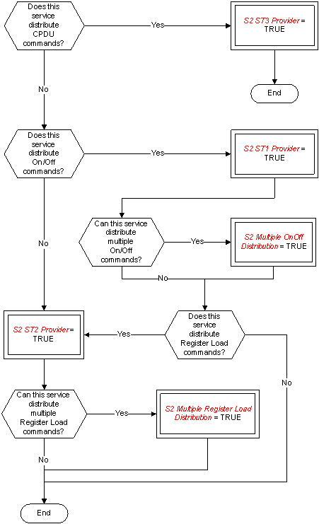 Figure: Tailoring choices for the device command distribution service
Service requests and reports
Distributing On/Off commands (S2 ST1 Provider = TRUE)
The telecommand for distribution of On/Off commands (Type = 2, Subtype = 1) is:
|
|
N |
Address |
|
|||
|
|
S2 N |
S2 OnOff Address |
|
|||
|
|
S2 Multiple OnOff Distribution = TRUE |
|
|
|||
Distributing register load commands (S2 ST2 Provider = TRUE)
The telecommand for distribution of register load commands (Type = 2, Subtype = 2) is:
|
|
|

|
|
|
|
|
|
Register Load Instruction |
|
|
|
|
N |
Register Address |
Register Data |
|
|
|
S2 N |
S2 Register Load Address |
Record |
|
|
|
S2 Multiple Register Load Distribution = TRUE |
|
|
|
Distributing CPDU commands (S2 ST3 Provider = TRUE)
The telecommand for distribution of CPDU commands (Type = 2, Subtype = 3) is:
|
|

|
|
|
|
|
Output Line ID |
Duration |
|
|
|
PTC 2 PFC 8 |
PTC 3 PFC 4 |
|
Housekeeping and diagnostic data reporting service
The PUS service model
This service provides for the reporting of low-level engineering data to the ground for the purposes of health monitoring, end-to-end telecommand verification and troubleshooting of on-board anomalies. To this end, two independent but functionally identical sub-services are provided, namely:
housekeeping data reporting;
diagnostic data reporting i.e. the reporting of engineering data for anomaly investigation purposes.
These are implemented as different sub-services in the sense that different subtypes are used for telemetry and telecommand packets, to facilitate differential routing and processing on the ground.
The service revolves around the concept of a Reporting Definition, which is a definition of a set of parameter samples that constitute a parameter report i.e. a housekeeping or diagnostic data packet. For housekeeping packets, there is a pre-defined set of reporting definitions stored on-board the satellite. These are designed by the satellite manufacturer according to the perceived requirements for the housekeeping monitoring of the mission. A service option exists for modifying these definitions dynamically during the course of the mission, including modifying parameter sampling rates, the addition of completely new definitions and the deletion of obsolete ones. This capability accommodates the experience with past missions that the optimum housekeeping sampling patterns evolves with time reflecting the degradation of in-orbit equipment performance and the onset of anomalies. However, these capabilities for modifying reporting definitions are fundamental to the concept of the diagnostic data reporting sub-service, since the nature of anomalies is by definition not known in advance. Diagnostic packets are expected to be used predominantly to sample small sets of parameters at high rates in order to gain a better understanding of on-board anomalies from a higher resolution of associated information. In order to be able to achieve this high-rate sampling in diagnostic mode, the on-board design permits the sampling of successive instances of a given parameter at a specified minimum sampling interval given by the mission constant <DIAG_MIN_INTERV>. This sampling interval constitutes a time unit for the specification of several other time parameters in the PUS e.g. the collection interval for a housekeeping or diagnostic report.
In order to relieve the loading of the telemetry bandwidth with engineering data that has not changed in value, a service option is provided to report data only when something within a packet has changed value significantly. This concept is known as filtering and the ground can specify which parameters in the packet are to be checked on-board for a change of value and can also specify a threshold for the change of value (thus eliminating “noisy” values or changes that are considered operationally insignificant). When a packet has been set to filtered mode, a timeout comes into effect, whereby a one-shot packet is generated after a specified time interval if no change in parameter value has occurred in the meantime. This measure ensures that extensive periods of time do not elapse without the occurrence of a parameter report. Another important concept for this service is that of parameter sampling time on-board. With conventional time-division multiplexed (TDM) telemetry, the on-board sampling time of a parameter was derived directly from its location in the telemetry frame or format. This timing information is of paramount importance for correlating engineering measurements with external events or for investigating in detail the nature of anomalous behaviour. With the use of packet telemetry, the operational requirements still remain for knowing the absolute and relative sampling times of telemetry parameters, either from an intrinsic knowledge of the on-board sampling sequences or by directly measuring the on-board sampling times which are then reported in the telemetry. The accuracy with which the absolute and relative on-board sampling of parameters is known is given by the mission constants <PARAM_ABS_SAMPL_TIME> and <PARAM_REL_SAMPL_TIME>, respectively.
The PUS draws a clear distinction between the functions of packet generation and packet forwarding. Packet generation is a function that is managed at service level, whilst the control of packet forwarding to the ground is handled by a dedicated service at application process level (see Annex A.13). The diagnostic sub-service implements the ability to control packet generation, since diagnostic packets are foreseen to be “switched on and off” according to need. With the housekeeping sub-service, the capability goes hand-in-hand with the capability to modify or create housekeeping reporting definitions in-orbit.
A structure identifier (SID) is associated with each distinct reporting definition and the corresponding telemetry packet. The SID is used on the ground, together with the APID and the knowledge of the nature of the packet (i.e. whether it is a housekeeping or a diagnostic packet), to identify the telemetry packet and to interpret its content. The SID is unique for the service and packet nature (i.e. housekeeping or diagnostic), however different application processes can use the same values of SID.
Service tailoring data
The tailoring choices for the housekeeping and diagnostic reporting service are shown in Figure A-4 (Views 1 to 5).
 Figure: Tailoring choices for the housekeeping and diagnostic data reporting service (View 1)
 Figure A-4: Tailoring choices for the housekeeping and diagnostic data reporting service (View 2)
 Figure A-4: Tailoring choices for the housekeeping and diagnostic data reporting service (View 3)
 Figure A-4: Tailoring choices for the housekeeping and diagnostic data reporting service (View 4)
 Figure A-4: Tailoring choices for the housekeeping and diagnostic data reporting service (View 5)#### Service requests and reports
The requests and reports relating to the housekeeping data reporting sub-service are presented first, followed by those for the diagnostic data reporting sub-service.
Defining new housekeeping parameter report (S3 ST1 ST3 ST5 and ST6 Provider = TRUE)
The telecommand for the definition of a new housekeeping parameter report (Type = 3, Subtype = 1) is:
|
|
|
|
|
|
|

|
|
||
|
|
|
|
|

|
|
|
|

|
|
|
|
SID |
Collection Interval |
NPAR1 |
Parameter# |
NFA |
NREP |
NPAR2 |
Parameter# |
|
|
|
S3 SID |
S3 Collection Interval |
S3 NPAR1 |
S3 Parameter Number |
S3 NFA |
S3 NREP |
S3 NPAR2 |
S3 Parameter Number |
|
|
|
|
S3 HK Implicit Collection Interval = FALSE |
|
|
|
|
|
|
|
Clearing housekeeping parameter report definitions (S3 ST1 ST3 ST5 and ST6 Provider = TRUE)
The telecommand to clear one or more housekeeping parameter report definitions (Type = 3, Subtype = 3) is:
|
|
|

|
|
||
|
|
NSID |
SID |
|
||
|
|
S3 NSID |
S3 SID |
|
||
|
|
S3 HK Multiple Clear SID = TRUE |
|
|
||
Controlling the generation of housekeeping parameter reports (S3 ST1 ST3 ST5 and ST6 Provider = TRUE)
The telecommand to enable (Type = 3, Subtype = 5) or disable (Type = 3, Subtype = 6) the generation of one or more housekeeping parameters report definitions is:
|
|
|

|
|
|
|
NSID |
SID |
|
|
|
S3 NSID |
S3 SID |
|
|
|
S3 HK Multiple Control SID = TRUE |
|
|
Reporting housekeeping parameter report definitions (S3 ST9 and ST10 Provider = TRUE)
The telecommand to request a report of one or more housekeeping parameter report definitions (Type = 3, Subtype = 9) is:
|
|
|

|
|
|
|
NSID |
SID |
|
|
|
S3 NSID |
S3 SID |
|
|
|
S3 HK Multiple Report SID = TRUE |
|
|
The corresponding report containing the requested housekeeping parameter report definitions (Type = 3, Subtype = 10) is:
|
|
|

|
|
|||||||
|
|
|
|
|
|
|
|

|
|
||
|
|
|
|
|
|

|
|
|
|

|
|
|
|
NSID |
SID |
Collection Interval |
NPAR1 |
Parameter# |
NFA |
NREP |
NPAR2 |
Parameter# |
|
|
|
S3 NSID |
S3 SID |
S3 Collection Interval |
S3 NPAR1 |
S3 Parameter Number |
S3 NFA |
S3 NREP |
S3 NPAR2 |
S3 Parameter Number |
|
|
|
S3 HK Multiple Report SID = TRUE |
|
S3 HK Implicit Collection Interval = FALSE |
|
|
|
|
|
|
|
Reporting housekeeping parameter sampling-time offsets (S3 ST13 and ST15 Provider = TRUE)
The telecommand to request a report of housekeeping parameter sampling-time offsets (Type = 3, Subtype = 13) is:
|
SID |
|
|
S3 SID |
The corresponding sampling-time report (Type = 3, Subtype = 15) is:
|
|
|

|
|
|||||||
|
|
SID |
Time Offset 1st Parameter |
|
Time Offset Last Parameter |
|
|||||
|
|
S3 SID |
S3 Time Offset |
|
S3 Time Offset |
|
|||||
Selecting housekeeping parameter report generation mode (S3 ST17 and ST19 Provider = TRUE)
The telecommand to select the Periodic Generation Mode for a given housekeeping reporting definition (Type = 3, Subtype = 17) is:
|
SID |
|
|
S3 SID |
The telecommand to select the Filtered Generation Mode for a given housekeeping reporting definition (Type = 3, Subtype = 19) is:
|
|
|
|
|

|
|
|||||||
|
|
SID |
Timeout |
N |
Parameter# |
Threshold Type |
Threshold |
|
|||||
|
|
S3 SID |
S3 Timeout |
S3 N |
S3 Parameter Number |
S3 Threshold Type |
S3 Threshold |
|
|||||
|
|
|
S3 HK Default Timeout = FALSE |
S3 HK Filtered Parameters = TRUE AND S3 HK Implicit Filter = FALSE |
|
S3 HK Default Threshold = FALSE AND S3 HK Default Threshold Type = FALSE |
S3 HK Default Threshold = FALSE |
|
|||||
Reporting unfiltered housekeeping parameters (S3 ST21 and ST23 Provider = TRUE)
The telecommand to request a report of the parameters that are unfiltered for a given housekeeping reporting definition (Type = 3, Subtype = 21) is:
|
SID |
|
|
S3 SID |
The corresponding report (Type = 3, Subtype = 23) is:
|
|
|
|

|
|
|||||||
|
|
SID |
N |
Parameter# |
Threshold Type |
Threshold |
|
|||||
|
|
S3 SID |
S3 N |
S3 Parameter Number |
S3 Threshold Type |
S3 Threshold |
|
|||||
|
|
|
|
|
S3 HK Default Threshold = FALSE AND S3 HK Default Threshold Type = FALSE |
S3 HK Default Threshold = FALSE |
|
|||||
Reporting housekeeping data (S3 HK Provider = TRUE)
The reports of the values of a set of housekeeping parameters (Type = 3, Subtype = 25) is:
|
|
|
|
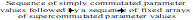
|
|
|||||
|
|
SID |
Mode |
Parameters |
|
|||||
|
|
S3 SID |
S3 Mode |
Any |
|
|||||
|
|
|
S3 ST17 and ST19 Provider = TRUE |
|
|
|||||
Defining new diagnostic parameter report (S3 Diagnostic Provider = TRUE)
The telecommand for the definition of a new diagnostic parameter report (Type = 3, Subtype = 2) is:
|
|
|

|
|
||||||
|
|
|

|
|
|
|

|
|
||
|
|
SID |
Collection Interval |
NPAR1 |
Parameter# |
NFA |
NREP |
NPAR2 |
Parameter# |
|
|
|
S3 SID |
S3 Collection Interval |
S3 NPAR1 |
S3 Parameter Number |
S3 NFA |
S3 NREP |
S3 NPAR2 |
S3 Parameter Number |
|
|
|
|
S3 Diagnostic Implicit Collection Interval = FALSE |
|
|
|
|
|
|
|
Clearing diagnostic parameter report definitions (S3 Diagnostic Provider = TRUE)
The telecommand to clear one or more diagnostic parameter report definitions (Type = 3, Subtype = 4) is:
|
|
|

|
|
|
|
NSID |
SID |
|
|
|
S3 NSID |
S3 SID |
|
|
|
S3 Diagnostic Multiple Clear SID = TRUE |
|
|
Controlling the generation of diagnostic parameter reports (S3 Diagnostic Provider = TRUE)
The telecommand to enable (Type = 3, Subtype = 7) or disable (Type = 3, Subtype = 8) the generation of one or more diagnostic parameters report definitions is:
|
|
|

|
|
|
|
NSID |
SID |
|
|
|
S3 NSID |
S3 SID |
|
|
|
S3 Diagnostic Multiple Control SID = TRUE |
|
|
Reporting diagnostic parameter report definitions (S3 ST11 and ST12 Provider = TRUE)
The telecommand to request a report of one or more diagnostic parameter report definitions (Type = 3, Subtype = 11) is:
|
|
|

|
|
|
|
NSID |
SID |
|
|
|
S3 NSID |
S3 SID |
|
|
|
S3 Diagnostic Multiple Report SID = TRUE |
|
|
The corresponding report containing the requested diagnostic parameter report definitions (Type = 3, Subtype = 12) is:
|
|
|

|
|
||||||||||||
|
|
|
|
|
|
|
|

|
|
|||||||
|
|
|
|
|
|

|
|
|
|

|
|
|||||
|
|
NSID |
SID |
Collection Interval |
NPAR1 |
Parameter# |
NFA |
NREP |
NPAR2 |
Parameter# |
|
|||||
|
|
S3 NSID |
S3 SID |
S3 Collection Interval |
S3 NPAR1 |
S3 Parameter Number |
S3 NFA |
S3 NREP |
S3 NPAR2 |
S3 Parameter Number |
|
|||||
|
|
S3 Diagnostic Multiple Report SID = TRUE |
|
S3 Diagnostic Implicit Collection Interval = FALSE |
|
|
|
|
|
|
|
|||||
Reporting diagnostic parameter sampling-time offsets (S3 ST14 and ST16 Provider = TRUE)
The telecommand to request a report of diagnostic parameter sampling-time offsets (Type = 3, Subtype = 14) is:
|
SID |
|
|
S3 SID |
The corresponding sampling-time report (Type = 3, Subtype = 16) is:
|
|
|

|
|
|||||||
|
|
SID |
Time Offset 1st Parameter |
|
Time Offset Last Parameter |
|
|||||
|
|
S3 SID |
S3 Time Offset |
|
S3 Time Offset |
|
|||||
Selecting diagnostic parameter report generation mode (S3 ST18 and ST20 Provider = TRUE)
The telecommand to select the Periodic Generation Mode for a given diagnostic reporting definition (Type = 3, Subtype = 18) is:
|
SID |
|
|
S3 SID |
The telecommand to select the Filtered Generation Mode for a given diagnostic reporting definition (Type = 3, Subtype = 20) is:
|
|
SID |
Timeout |
N |
Parameter# |
Threshold Type |
Threshold |
|
|||||
|
|
S3 SID |
S3 Timeout |
S3 N |
S3 Parameter Number |
S3 Threshold Type |
S3 Threshold |
|
|||||
|
|
|
S3 Diagnostic Default Timeout = FALSE |
S3 Diagnostic Filtered Parameters = TRUE AND S3 Diagnostic Implicit Filter = FALSE |
|
S3 Diagnostic Default Threshold = FALSE AND S3 Diagnostic Default Threshold Type = FALSE |
S3 Diagnostic Default Threshold = FALSE |
|
|||||
Reporting unfiltered diagnostic parameters (S3 ST22 and ST24 Provider = TRUE)
The telecommand to request a report of the parameters that are unfiltered for a given diagnostic reporting definition (Type = 3, Subtype = 22) is:
|
SID |
|
|
S3 SID |
The corresponding report (Type = 3, Subtype = 24) is:
|
|
SID |
N |
Parameter# |
Threshold Type |
Threshold |
|
|||||
|
|
S3 SID |
S3 N |
S3 Parameter Number |
S3 Threshold Type |
S3 Threshold |
|
|||||
|
|
|
|
|
S3 Diagnostic Default Threshold = FALSE AND S3 Diagnostic Default Threshold Type = FALSE |
S3 Diagnostic Default Threshold = FALSE |
|
|||||
Reporting diagnostic data (S3 Diagnostic Provider = TRUE)
The report of the values of a set of diagnostic parameters (Type = 3, Subtype = 26) is:
|
|
|
|

|
|
|||||
|
|
SID |
Mode |
Parameters |
|
|||||
|
|
S3 SID |
S3 Mode |
Any |
|
|||||
|
|
|
S3 ST18 and ST20 Provider = TRUE |
|
|
|||||
Parameter statistics reporting service
The PUS service model
This service provides the capability for evaluating a standard set of statistics (maximum, minimum, mean and standard deviation) for a specified list of parameters and reporting the results to the ground. The ground can (optionally) modify the on-board list of parameters to be evaluated and the on-board interval for sampling these parameters.
Different options exist for reporting the results; this can be done either periodically or on request from the ground. In either case, a further option exists to reset the results whenever they are reported or to continue accumulating the results until the process is explicitly reset by ground command.
Service tailoring data
The tailoring choices for the parameter statistics reporting service are shown in Figure A-5.
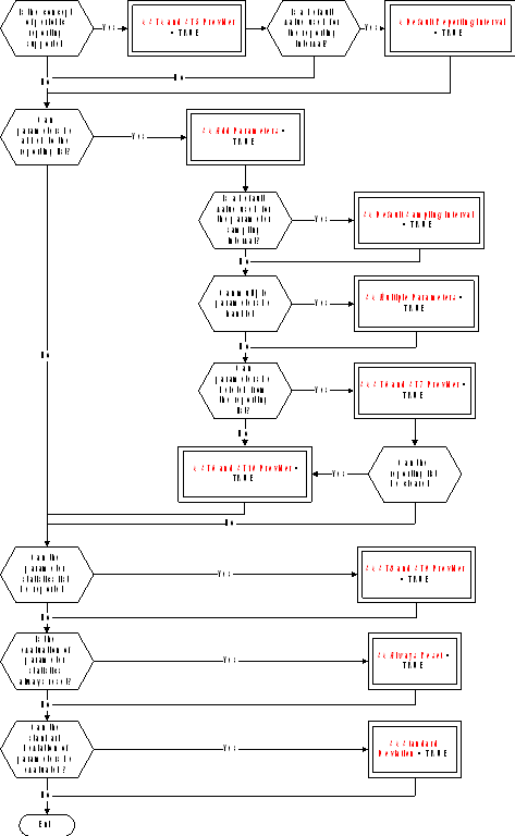 FigureTailoring choices for the parameter statistics reporting service
Service requests and reports
Reporting the parameter statistics results
The telecommand to request a report of the parameter statistics results (Type = 4, Subtype = 1) is:
|
|
Reset Flag |
|
|
|
|
S4 Reset Flag |
|
|
|
|
S4 Always Reset = FALSE |
|
|
The corresponding telemetry report (Type = 4, Subtype = 2) is:
|
|
|
|

|
|
|||||||||||
|
|
tstart |
NPAR |
Parameter# |
Maxval |
tmax |
Minval |
tmin |
Meanval |
Stddevval |
|
|||||
|
|
S4 Time |
S4 NPAR |
S4 Parameter Number |
Deduced |
S4 Time |
Deduced |
S4 Time |
Deduced |
Deduced |
|
|||||
|
|
|
|
|
|
|
|
|
|
S4 Standard Deviation = TRUE |
|
|||||
Resetting the parameter statistics reporting
The telecommand to request a reset of the parameter statistics reporting (Type = 4, Subtype = 3) has no application data.
Selecting the parameter statistics reporting mode (S4 ST4 and ST5 Provider = TRUE)
The telecommand to request enabling of the periodic reporting of the parameter statistics (Type = 4, Subtype = 4) is:
|
|
Reporting Interval |
|
|
|
|
S4 Relative Time |
|
|
|
|
S4 Default Reporting Interval = FALSE |
|
|
The telecommand to request disabling of the periodic reporting of the parameter statistics (Type = 4, Subtype = 5) has no application data.
Adding parameters to the parameter statistics list
The telecommand to add parameters to the parameter statistics list (Type = 4, Subtype = 6) is:
|
|
|

|
|
||||
|
|
NPAR |
Parameter# |
Sampling Interval |
|
|||
|
|
S4 NPAR |
S4 Parameter Number |
S4 Relative Time |
|
|||
|
|
S4 Multiple Parameters = TRUE |
|
S4 Default Sampling Interval = FALSE |
|
|||
Deleting parameters from the parameter statistics list (S4 ST6 and ST7 Provider = TRUE)
The telecommand to request deletion of parameters from the parameter statistics list (Type = 4, Subtype = 7) is:
|
|
|

|
|
|
|
|
NPAR |
Parameter# |
|
|
|
|
S4 NPAR |
S4 Parameter Number |
|
|
|
|
S4 Multiple Parameters = TRUE |
|
|
|
Reporting the parameter statistics list (S4 ST8 and ST9 Provider = TRUE)
The telecommand to request reporting of the parameter statistics list (Type = 4, Subtype = 8) has no application data.
The corresponding report (Type = 4, Subtype = 9) is:
|
|
|
|

|
|
||||||
|
|
Reporting Interval |
NPAR |
Parameter# |
Sampling Interval |
|
|||||
|
|
S4 Relative Time |
S4 NPAR |
S4 Parameter Number |
S4 Relative Time |
|
|||||
|
|
S4 Default Reporting Interval = FALSE |
|
|
S4 Default Sampling Interval = FALSE |
|
|||||
Clearing the parameter statistics list (S4 ST6 and ST10 Provider = TRUE)
The telecommand to request clearing of the parameter statistics list (Type = 4, Subtype = 10) has no application data.
Event reporting service
The PUS service model
This service provides the capability for reporting to the ground the occurrence of on-board events of any nature. It is expected that this service is used to report:
failures and anomalous behaviour;
other detected events that are of operational significance whilst not anomalous in nature e.g. payload external events detected by an experiment;
actions taken autonomously on-board (and possibly their outcome).
The event reports contain all necessary ancillary information used by the ground to understand the nature and circumstances of the reported event.
An option exists to disable the generation of specified event reports (and also to enable them) in order to reduce the on-board processing load.
Service tailoring data
The tailoring choices for the event reporting service are shown in Figure A-6.
 Figure: Tailoring choices for the event reporting service
Service requests and reports
Reporting events
All event reports have the same structure. The reports are:
Normal/Progress Report (Type = 5, Subtype = 1);
Error/Anomaly Report - Low Severity (Type = 5, Subtype = 2);
Error/Anomaly Report - Medium Severity (Type = 5, Subtype = 3);
Error/Anomaly Report - High Severity (Type = 5, Subtype = 4).
|
|
|

|
|
|||
|
|
RID |
Parameters |
|
|||
|
|
S5 RID |
Any |
|
|||
Controlling the generation of event reports
The telecommand to enable (Type = 5, Subtype = 5) or disable (Type = 5, Subtype = 6) the generation of event reports is:
|
|
|

|
|
|||
|
|
NRID |
RID |
|
|||
|
|
S5 NRID |
S5 RID |
|
|||
|
|
S5 Multiple RIDs = TRUE |
|
|
|||
Memory management service
The PUS service model
This service provides the capabilities for loading and dumping on-board memories and also for requesting the application process to check a memory area and report the result. A given application process can have access to none, one or several on-board memories and each on-board memory can use one of the following addressing techniques:
base reference plus offset;
absolute addressing.
The first of these techniques (base reference plus offset) can be used to supply a symbolic name, in the form of a character string, that corresponds to a well-defined address within the memory block.
Service tailoring data
The tailoring choices for the memory management service are shown in Figure A-7 (Views 1 and 2).
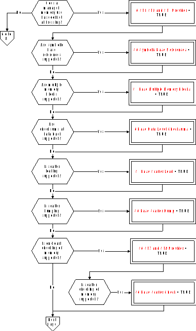 Figure: Tailoring choices for the memory management service (View 1)
 Figure A-7: Tailoring choices for the memory management service (View 2)#### Service requests and reports
Loading data in memory using base plus offsets (S6 ST1 ST3 and ST4 Provider = TRUE)
The telecommand to load data into one or more areas of a memory block defined using a base reference plus offsets (Type = 6, Subtype = 1) is:
|
|
|
|
|

|
|
||||||||
|
|
Memory ID |
Base |
N |
Offset |
Length |
Data |
Checksum |
|
|||||
|
|
S6 Memory ID |
S6 Base |
S6 N |
S6 Offset |
Variable Octet String |
PTC 6 PFC 16 |
|
||||||
|
|
S6 Base Multiple Memory Blocks = TRUE |
|
S6 Base Scatter Load = TRUE |
|
|
|
S6 Base Data Level Checksums = TRUE |
|
|||||
Loading data in memory using absolute addresses (S6 ST2 ST5 and ST6 Provider = TRUE)
The telecommand to load data to one or more areas of a memory block defined using absolute addresses (Type = 6, Subtype = 2) is:
|
|
|
|

|
|
||||||||
|
|
Memory ID |
N |
Start Address |
Length |
Data |
Checksum |
|
|||||
|
|
S6 Memory ID |
S6 N |
S6 Start Address |
Variable Octet String |
PTC 6 PFC 16 |
|
||||||
|
|
S6 Absolute Multiple Memory Blocks = TRUE |
S6 Absolute Scatter Load = TRUE |
|
|
|
S6 Absolute Data Level Checksums = TRUE |
|
|||||
Dumping memory using base plus offsets (S6 ST1 ST3 and ST4 Provider = TRUE)
The telecommand to dump the contents of one or more areas of a memory block defined using a base reference plus offsets (Type = 6, Subtype = 3) is:
|
|
|
|
|

|
|
||||||
|
|
Memory ID |
Base |
N |
Offset |
Length |
|
|||||
|
|
S6 Memory ID |
S6 Base |
S6 N |
S6 Offset |
S6 Length |
|
|||||
|
|
S6 Base Multiple Memory Blocks = TRUE |
|
S6 Base Scatter Dump = TRUE |
|
|
|
|||||
The corresponding memory dump report (Type = 6, Subtype = 4) is:
|
|
|
|
|

|
|
||||||||
|
|
Memory ID |
Base |
N |
Offset |
Length |
Data |
Checksum |
|
|||||
|
|
S6 Memory ID |
S6 Base |
S6 N |
S6 Offset |
Variable Octet String |
PTC 6 PFC 16 |
|
||||||
|
|
S6 Base Multiple Memory Blocks = TRUE |
|
S6 Base Scatter Dump = TRUE |
|
|
|
S6 Base Data Level Checksums = TRUE |
|
|||||
Dumping memory using absolute addresses (S6 ST2 ST5 and ST6 Provider = TRUE)
The telecommand to dump the contents of one or more areas of a memory block defined using absolute addresses (Type = 6, Subtype = 5) is:
|
|
|
|

|
|
||||||
|
|
Memory ID |
N |
Start Address |
Length |
|
|||||
|
|
S6 Memory ID |
S6 N |
S6 Start Address |
S6 Length |
|
|||||
|
|
S6 Absolute Multiple Memory Blocks = TRUE |
S6 Absolute Scatter Dump = TRUE |
|
|
|
|||||
The corresponding memory dump report (Type = 6, Subtype = 6) is:
|
|
|
|

|
|
||||||||
|
|
Memory ID |
N |
Start Address |
Length |
Data |
Checksum |
|
|||||
|
|
S6 Memory ID |
S6 N |
S6 Start Address |
Variable Octet String |
PTC 6 PFC 16 |
|
||||||
|
|
S6 Absolute Multiple Memory Blocks = TRUE |
S6 Absolute Scatter Dump = TRUE |
|
|
|
S6 Absolute Data Level Checksums = TRUE |
|
|||||
Checking memory using base plus offsets (S6 ST7 and ST8 Provider = TRUE)
The telecommand to check the contents of one or more areas of a memory block defined using a base reference plus offsets (Type = 6, Subtype = 7) is:
|
|
|
|
|

|
|
||||||
|
|
Memory ID |
Base |
N |
Offset |
Length |
|
|||||
|
|
S6 Memory ID |
S6 Base |
S6 N |
S6 Offset |
S6 Length |
|
|||||
|
|
S6 Base Multiple Memory Blocks = TRUE |
|
S6 Base Scatter Check = TRUE |
|
|
|
|||||
The corresponding memory check report (Type = 6, Subtype = 8) is:
|
|
|
|
|

|
|
|||||||
|
|
Memory ID |
Base |
N |
Offset |
Length |
Checksum |
|
|||||
|
|
S6 Memory ID |
S6 Base |
S6 N |
S6 Offset |
S6 Length |
PTC 6 PFC 16 |
|
|||||
|
|
S6 Base Multiple Memory Blocks = TRUE |
|
S6 Base Scatter Check = TRUE |
|
|
|
|
|||||
Checking memory using absolute addresses (S6 ST9 and ST10 Provider = TRUE)
The telecommand to check the contents of one or more areas of a memory block defined using absolute addresses (Type = 6, Subtype = 9) is:
|
|
|
|

|
|
|||||||
|
|
Memory ID |
N |
Start Address |
Length |
|
||||||
|
|
S6 Memory ID |
S6 N |
S6 Start Address |
S6 Length |
|
||||||
|
|
S6 Absolute Multiple Memory Blocks = TRUE |
S6 Absolute Scatter Check = TRUE |
|
|
|
||||||
The corresponding memory check report (Type = 6, Subtype = 10) is:
|
|
|
|

|
|
|||||||
|
|
Memory ID |
N |
Start Address |
Length |
Checksum |
|
|||||
|
|
S6 Memory ID |
S6 N |
S6 Start Address |
S6 Length |
PTC 6 PFC 16 |
|
|||||
|
|
S6 Absolute Multiple Memory Blocks = TRUE |
S6 Absolute Scatter Check = TRUE |
|
|
|
|
|||||
Function management service
The PUS service model
This service provides the capabilities for controlling those software functions of an application process that are not implemented as standard or as mission-specific services. The specialized role of a given application process is reflected in the internal functions that it supports. For example:
attitude or orbit manoeuvres for an application process hosted within an AOCS processor;
payload control for an application process hosted within an experiment processor.
A Function ID is defined at the level of each individual control for the corresponding function and run-time parameters can also be loaded from ground.
Service tailoring data
The tailoring choices for the function management service are shown in Figure A-8.
 Figure: Tailoring choices for the function management service
Service requests and reports
Perform function (S8 Provider = TRUE)
There are two possibilities for the telecommand to perform a function (Type = 8, Subtype = 1). Where the full set of parameters is always provided (or where the function has no parameters), the telecommand is:
|
|
|

|
|
|
|
|
Function ID |
Parameters |
|
|
|
|
S8 Function ID |
Any |
|
|
|
|
|

|
|
|
Where a sub-set of parameters can be supplied (S8 Parameter Subset = TRUE), the telecommand is:
|
|
|
|

|
|
||||||
|
|
Function ID |
N |
Parameter# |
Value |
|
|||||
|
|
S8 Function ID |
S8 N |
S8 Parameter Number |
Deduced |
|
|||||
Time management service
The PUS service model
This service provides the generation of the standard time report (for application process = 0) and the optional capability to control the frequency of generation of this report. Note that the latter capability may be provided by a different application process from that which generates the time report itself.
Unless a very basic time reporting capability is provided, the status of the time reporting service is included in the time report itself.
The standard time report is the means that the ground uses to perform correlation between on-board time (OBT) and ground time, which is Universal Time Coordinated (UTC). The procedures used on the ground for this correlation are fully defined in ECSSEST-7041. This time correlation is used by many ground functions, for example:
by the commanding system to ensure that any OBT time fields contained in uplinked commands destined to the on-board operations scheduling service use the latest available time correlation;
by any ground function that uses the absolute time of on-board sampling of a given telemetry parameter (this is deduced from the packet time and the sampling time offset which is known for each parameter in the packet).
Service tailoring data
The tailoring choices for the time management service are shown in Figure A-9.
 Figure: Tailoring choices for the time management service
Only one application process is an S9 ST1 Provider.
Service requests and reports
Controlling the time report generation rate (S9 ST1 Provider = TRUE)
The telecommand to change the rate of generation of the time report (Type = 9, Subtype = 1) is:
|
Rate |
|
|
Unsigned Integer (1 octet) |
Time reporting (S9 ST2 Provider = TRUE)
The Spacecraft Time Source Packet (Type = 9, Subtype = 2) is:
|
|
Rate |
Satellite Time |
Status |
|
||
|
|
Unsigned Integer (1 octet) |
S9 Satellite Time |
S9 Status |
|
||
|
|
S9 ST1 Provider = TRUE |
|
S9 Basic Report = FALSE |
|
||
On-board operations scheduling service
The PUS service model
This service provides the capability to schedule telecommands for distribution on-board when their release times become due. The basic functionalities of the service include the capability to add and delete commands from the on-board schedule and to enable and disable the on-board schedule. A number of more advanced (and optional) capabilities are also provided within the framework of this service, including:
the capability to report the current contents of the on-board schedule to the ground;
the capability to load telecommands into different on-board sub-schedules. A sub-schedule is a group of commands that can be independently controlled (as an entity) from the ground;
the capability to define interlocks between telecommands within the same sub-schedule. An interlock allows the release of a telecommand to be dependent upon the successful (or alternatively, unsuccessful) execution of a previous telecommand released from the on-board schedule;
the capability to time-shift a group of telecommands i.e. to change their release times by the same relative time, without the need to delete and re-load them from ground. This is effectively a “re-scheduling” capability;
the capability to define the release time relative to an on-board event. A number of standard events are defined, however this list can be added to on a mission-specific basis.
Service tailoring data
The tailoring choices for the on-board operations scheduling service are shown in Figure A-10 (Views 1 to 3).
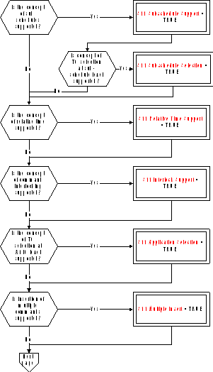 Figure: Tailoring choices for the on-board operations scheduling service (View 1)
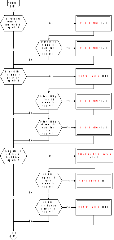 Figure A-10: Tailoring choices for the on-board operations scheduling service (View 2)
 Figure A-10: Tailoring choices for the on-board operations scheduling service (View 3):::note
S11 Scattering Support = TRUE implies that either S11 ST5 Provider = TRUE OR S11 ST15 Provider = TRUE OR S11 ST16 and ST10 Provider = TRUE.
:::
Figure A-10: Tailoring choices for the on-board operations scheduling service (View 3):::note
S11 Scattering Support = TRUE implies that either S11 ST5 Provider = TRUE OR S11 ST15 Provider = TRUE OR S11 ST16 and ST10 Provider = TRUE.
:::
Service requests and reports
Controlling the release of telecommands
The telecommands to enable (Type = 11, Subtype = 1) and to disable (Type = 11, Subtype = 2) the release of selected telecommands are:
|
|
|

|
|
|||||||
|
|
|
|
|

|
|
|||||
|
|
N1 |
Sub-schedule ID |
N2 |
Application Process ID |
|
|||||
|
|
S11 N1 |
S11 Subschedule ID |
S11 N2 |
S11 APID |
|
|||||
Resetting the command schedule
The telecommand to reset the command schedule (Type = 11, Subtype = 3) has no application data.
Inserting telecommands in the command schedule
The telecommand to insert telecommands in the command schedule (Type =11, Subtype = 4) is:
|
|
Sub-schedule ID |
N |
|
|||||||||||||||
|
|
S11 Subschedule ID |
S11 N |
|
|||||||||||||||
|
|
S11 Subschedule Support = TRUE |
S11 Multiple Insert = TRUE |
|
|||||||||||||||
|
|

|
|
||||||||||||||||
|
|
Interlock Set ID |
Interlock Assessed ID |
Assessment Type |
Scheduling Event |
Abs/Rel Time Tag |
Execution Timeout |
Telecommand Packet |
|
||||||||||
|
|
S11 Interlock ID |
S11 Interlock ID |
S11 Assessment Type |
S11Scheduling Event |
S11 Absolute CUC Time or S11 Relative CUC Time |
S11 Relative CUC Time |
Any TC |
|
||||||||||
|
|
|
Optional (TC is interlock dependent) |
S11 Relative Time Support = TRUE |
|
Optional (TC sets an interlock) |
|
|
|||||||||||
Deleting telecommands from the command schedule
Deleting telecommands (S11 ST5 Provider = TRUE)
The request to delete sets of telecommands from the command schedule (Type = 11, Subtype = 5) is:
|
|
|

|
|
|||||||
|
|
N |
Application Process ID |
Sequence Count |
No. of Telecommands |
|
|||||
|
|
S11 N |
S11 APID |
S11 Sequence Count |
S11 Number of TCs |
|
|||||
|
|
S11 Scattering Support = TRUE |
|
|
|
|
|||||
Deleting telecommands over a time period (S11 ST6 Provider = TRUE)
The telecommand to delete commands from the command schedule over a time period (Type = 11, Subtype = 6) is:
|
|
|
|
|
|

|
|
|||||||
|
|
|
|
|
|
|
|

|
|
|||||
|
|
Range |
Time Tag 1 |
Time Tag 2 |
N1 |
Sub-schedule ID |
N2 |
Application Process ID |
|
|||||
|
|
S11 Range |
S11 Absolute CUC Time |
S11 Absolute CUC Time |
S11 N1 |
S11 Subschedule ID |
S11 N2 |
S11 APID |
|
|||||
|
|
|

|
|
|
|
||||||||
Time-shifting of telecommands in the command schedule
Time-shifting all telecommands (S11 ST15 Provider = TRUE)
The telecommand to time-shift all telecommands (Type = 11, Subtype = 15) is:
|
Time Offset |
|
S11 Relative CUC Time |
Time-shifting selected telecommands (S11 ST15 Provider = TRUE and S11 ST7 Provider = TRUE)
The telecommand to time-shift selected telecommands (Type = 11, Subtype = 7) is:
|
|
|
|

|
|
|||||||
|
|
Time Offset |
N |
Application Process ID |
Sequence Count |
No. of Telecommands |
|
|||||
|
|
S11 Relative CUC Time |
S11 N |
S11 APID |
S11 Sequence Count |
S11 Number of TCs |
|
|||||
|
|
|
S11 Scattering Support = TRUE |
|
|
|
|
|||||
Time-shifting selected telecommands over a time period (S11 ST15 Provider = TRUE and S11 ST7 Provider = TRUE and S11 ST8 Provider = TRUE)
The telecommand to time-shift selected telecommands over a time period (Type = 11, Subtype = 8) is:
|
|
Range |
Time Tag 1 |
Time Tag 2 |
Time Offset |
|
|
|
S11 Range |
S11 Absolute CUC Time |
S11 Absolute CUC Time |
S11 Relative CUC Time |
|
|
|
|

|
|
|
|
|
|
|

|
|
||
|
|

|
|
|||
|
|
N1 |
Sub-schedule ID |
N2 |
Application Process ID |
|
|
|
S11 N1 |
S11 Subschedule ID |
S11 N2 |
S11 APID |
|
Reporting of the command schedule contents
Detailed reporting of the command schedule (S11 ST16 and ST10 Provider = TRUE)
The telecommand to obtain a detailed report of all telecommands in the command schedule (Type = 11, Subtype = 16) has no application data.
The corresponding detailed report of the command schedule (Type = 11, Subtype = 10) is:
|
|
|

|
|||||||||
|
|
N |
Sub-schedule ID |
Interlock Set ID |
Interlock Assessed ID |
Assessment Type |
|
|||||
|
|
S11 N |
S11 Subschedule ID |
S11 Interlock ID |
S11 Interlock ID |
S11 Assessment Type |
|
|||||
|
|
|
S11 Subschedule Support = TRUE |
|
|
Optional (TC is interlock dependent) |
|
|||||
|

|
|
|||||||||
|
|
Scheduling Event |
Abs/Rel Time Tag |
Execution Timeout |
Telecommand Packet |
|
|||||
|
|
S11 Scheduling Event |
S11 Absolute CUC Time or S11 Relative CUC Time |
S11 Relative CUC Time |
Any TC |
|
|||||
|
|
S11 Relative Time Support = TRUE |
|
Optional (TC sets an interlock) |
|
|
|||||
Detailed reporting of a subset of the command schedule (S11 ST16 and ST10 Provider = TRUE and S11 ST9 Provider = TRUE)
The telecommand to obtain a detailed report of a selected subset of telecommands in the command schedule (Type = 11, Subtype = 9) is:
|
|
|

|
|
|||||||
|
|
N |
Application Process ID |
Sequence Count |
No. of Telecommands |
|
|||||
|
|
S11 N |
S11 APID |
S11 Sequence Count |
S11 Number of TCs |
|
|||||
|
|
S11 Scattering Support = TRUE |
|
|
|
|
|||||
Summary reporting of the command schedule (S11 ST17 and ST13 Provider = TRUE)
The telecommand to obtain a summary report of all telecommands in the command schedule (Type = 11, Subtype = 17) has no application data.
The corresponding summary report of the command schedule (Type = 11, Subtype = 13) is:
|
|
|

|
|
||||||||
|
|
N |
Sub-schedule ID |
Scheduling Event |
Abs/Rel Time Tag |
Application Process ID |
Sequence Count |
|
||||
|
|
S11 N |
S11 Subschedule ID |
S11 Scheduling Event |
S11 Absolute CUC Time or S11 Relative CUC Time |
S11 APID |
S11 Sequence Count |
|
||||
|
|
|
S11 Subschedule Support = TRUE |
S11 Relative Time Support = TRUE |
|
|
||||||
Summary reporting of a subset of the command schedule (S11 ST17 and ST13 Provider = TRUE and S11 ST12 Provider = TRUE)
The telecommand to obtain a summary report of a selected subset of telecommands in the command schedule (Type = 11, Subtype = 12) is the same as for (Type = 11, Subtype = 9).
Detailed reporting of the command schedule over a time period (S11 ST16 and ST10 Provider = TRUE and S11 ST9 Provider = TRUE and S11 ST11 Provider = TRUE)
The telecommand to obtain a detailed report of telecommands in the command schedule over a time period (Type = 11, Subtype = 11) is:
|
|
|
|

|
|
|||||||||
|
|
|
|
|

|
|
||||||||
|
|
Range |
Time Tag 1 |
Time Tag 2 |
N1 |
Sub-schedule ID |
N2 |
Application Process ID |
|
|||||
|
|
S11 Range |
S11 Absolute CUC Time |
S11 Absolute CUC Time |
S11 N1 |
S11 Subschedule ID |
S11 N2 |
S11 APID |
|
|||||
|
|
|

|
S11 Subschedule Selection = TRUE |
|
|
||||||||
Summary reporting of the command schedule over a time period (S11 ST17 and ST13 Provider = TRUE and S11 ST12 Provider = TRUE and S11 ST14 Provider = TRUE)
The telecommand to obtain a detailed report of telecommands in the command schedule over a time period (Type = 11, Subtype = 14) is the same as for (Type = 11, Subtype = 11).
Reporting of the status of the command schedule (S11 ST18 and ST19 Provider = TRUE)
The telecommand to obtain a status report of the command schedule (Type = 11, Subtype = 18) has no application data.
The corresponding status report (Type = 11, Subtype = 19) is:
|
|
|

|
|
|||||||||
|
|
|
|
|
|
|
|||||||
|
|
N1 |
Sub-schedule ID |
Status |
N2 |
Application Process ID |
Status |
|
|||||
|
|
S11 N1 |
S11 Subschedule ID |
S11 Status |
S11 N2 |
S11 APID |
S11 Status |
|
|||||
On-board monitoring service
The PUS service model
This service provides an on-board capability for health checking of parameters which is functionally similar to the monitoring of telemetry parameters that is performed on the ground (see also clause 6.6.3).
The service maintains a list of monitored parameters and their monitoring attributes and generates a report whenever a check transition is detected. Depending on the nature of the parameter being monitored, the check can be a limit set, a delta-check or an expected status check.
A number of more advanced (and optional) capabilities are also provided within the framework of this service, including:
the capability for the ground to add and delete parameters from the on-board monitoring list, or to modify the monitoring attributes of a parameter in the list;
the capability to define that a parameter is only checked if an associated “validity” parameter is TRUE;
the capability to specify several checks per parameter, where each check has an associated selection parameter;
the capability to generate event reports as the result of specified check transitions;
the capability to report, on request from the ground, the current on-board monitoring list or the list of parameters currently out-of-limits.
Service tailoring data
The tailoring choices available for the on-board monitoring service are shown in Figure A-11 (Views 1 to 3).
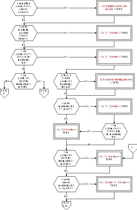 Figure: Tailoring choices for the on-board monitoring service (View 1)
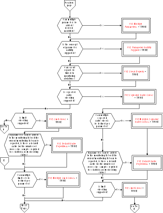 Figure A-11: Tailoring choices for the on-board monitoring service (View 2)
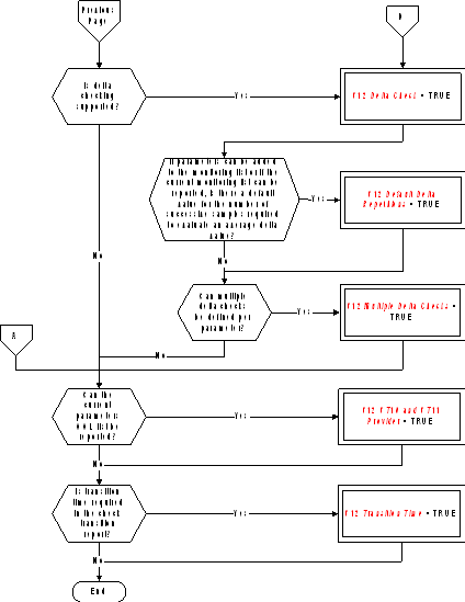 Figure A-11: Tailoring choices for the on-board monitoring service (View 3)#### Service requests and reports
Controlling the on-board monitoring
The telecommands to enable (Type = 12, Subtype = 1) and disable (Type = 12, Subtype = 2) the on-board monitoring are:
|
|
|

|
|
||
|
|
N |
Parameter# |
|
||
|
|
S12 N |
S12 Parameter Number |
|
||
|
|
S12 Multiple Enable and Disable = TRUE |
|
|
||
Changing the maximum reporting delay (S12 ST3 Provider = TRUE)
The telecommand to change the maximum reporting delay (Type = 12, Subtype = 3) is:
|
Max Reporting Delay |
|
|
S12 Maximum Reporting Delay |
Clearing the monitoring list (S12 ST4 Provider = TRUE and S12 ST5 Provider = TRUE)
The telecommand to clear the monitoring list (Type = 12, Subtype = 4) has no application data.
Adding parameters to the monitoring list (S12 ST5 Provider = TRUE)
The telecommand to add parameters to the monitoring list (Type = 12, Subtype = 5) is:
|
|
|
|
|
|

|
|||||||
|
|
Parameter Monitoring Interval |
Value #REP |
Delta #REP |
N |
Parameter# |
Validity Parameter# |
|
|||||
|
|
S12 Parameter Monitoring Interval |
S12 Repetitions |
S12 Repetitions |
S12 N |
S12 Parameter Number |
S12 Parameter Number |
|
|||||
|
|
S12 Default Monitoring Interval = FALSE |
S12 Default Value Repetitions = FALSE |
S12 Default Delta Repetitions = FALSE |
S12 Multiple Parameters = TRUE |
|
S12 Parameter Validity Support = TRUE |
|
|||||
|

|
||||||||||||
|
|
|

|
|
|||||||||
|
|
NOL |
Check Selection Parameter# |
Low Limit |
RID |
High Limit |
RID |
|
|||||
|
|
S12 NOL |
S12 Parameter Number |
Deduced |
S12 RID |
Deduced |
S12 RID |
|
|||||
|
|
S12 Multiple Limit Checks = TRUE |
|
S12 Event Reports = TRUE |
|
S12 Event Reports = TRUE |
|
||||||
|

|
||||||||||||
|
|
|

|
|
|||||||||
|
|
NOD |
Check Selection Parameter# |
Low Delta Threshold |
RID |
High Delta Threshold |
RID |
|
|||||
|
|
S12 NOD |
S12 Parameter Number |
Deduced |
S12 RID |
Deduced |
S12 RID |
|
|||||
|
|
S12 Multiple Delta Checks = TRUE |
|
S12 Event Reports = TRUE |
|
S12 Event Reports = TRUE |
|
||||||
|

|
|
|||||||
|
|
|

|
|
|||||
|
|
NOE |
Check Selection Parameter# |
Expected Value |
RID |
|
|||
|
|
S12 NOE |
S12 Parameter Number |
Deduced |
S12 RID |
|
|||
|
|
S12 Multiple Expected Value Checks = TRUE |
|
S12 Event Reports = TRUE |
|
||||
Deleting parameters from the monitoring list (S12 ST5 Provider = TRUE and S12 ST6 Provider = TRUE)
The telecommand to delete specified parameters from the monitoring list (Type = 12, Subtype = 6) is:
|
|
|

|
|
|
|
|
N |
Parameter# |
|
|
|
|
S12 N |
S12 Parameter Number |
|
|
|
|
S12 Multiple Parameters = TRUE |
|
|
|
Modifying the parameter checking information (S12 ST7 Provider = TRUE)
The telecommand to modify the checking information for specified parameters (Type = 12, Subtype = 7) is:
|
|
|

|
|||||
|
|
N |
Parameter# |
Validity Parameter# |
|
|||
|
|
S12 N |
S12 Parameter Number |
S12 Parameter Number |
|
|||
|
|
S12 Multiple Parameters = TRUE |
|
S12 Parameter Validity Support = TRUE |
|
|||
|

|
|||||||||||||
|
|
|

|
|
||||||||||
|
|
NOL |
Check Position |
Check Selection Parameter# |
Low Limit |
RID |
High Limit |
RID |
|
|||||
|
|
S12 NOL |
S12 Check Position |
S12 Parameter Number |
Deduced |
S12 RID |
Deduced |
S12 RID |
|
|||||
|
|
S12 Multiple Limit Checks = TRUE |
|
S12 Event Reports = TRUE |
|
S12 Event Reports = TRUE |
|
|||||||
|
|

|
||||||||||||
|
|
|

|
|
||||||||||
|
|
NOD |
Check Position |
Check Selection Parameter# |
Low Delta Threshold |
RID |
High Delta Threshold |
RID |
|
|||||
|
|
S12 NOD |
S12 Check Position |
S12 Parameter Number |
Deduced |
S12 RID |
Deduced |
S12 RID |
|
|||||
|
|
S12 Multiple Delta Checks = TRUE |
|
S12 Event Reports = TRUE |
|
S12 Event Reports = TRUE |
|
|||||||
|

|
|
||||||||
|
|
|

|
|
||||||
|
|
NOE |
Check Position |
Check Selection Parameter# |
Expected Value |
RID |
|
|||
|
|
S12 NOE |
S12 Check Position |
S12 Parameter Number |
Deduced |
S12 RID |
|
|||
|
|
S12 Multiple Expected Value Checks = TRUE |
|
S12 Event Reports = TRUE |
|
|||||
Reporting the current monitoring list contents (S12 ST8 and ST9 Provider = TRUE)
The telecommand to report the current monitoring list contents (Type = 12, Subtype = 8) has no application data.
The corresponding monitoring list contents report (Type = 12, Subtype = 9) is:
|
|
|
|
|

|
|||||||||||
|
|
Monitoring Status |
Maximum Reporting Delay |
N |
Parameter# |
Validity Parameter# |
Parameter Monitoring Interval |
Parameter Monitoring Status |
Value #REP |
|
||||||
|
|
S12 Monitoring Status |
S12 Maximum Reporting Delay |
S12 N |
S12 Parameter Number |
S12 Parameter Number |
S12 Parameter Monitoring Interval |
S12 Monitoring Status |
S12 Repetitions |
|
||||||
|
|
|
|
|
|
S12 Parameter Validity Support = TRUE |
|
|
S12 Default Value Repetitions = FALSE |
|
||||||
|

|
||||||||||||||||
|
|
|
|

|
|
|
|
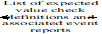
|
|||||||||
|
|
Delta #REP |
NOL |
Check Selection Parameter# |
Low Limit |
RID |
High Limit |
RID |
NOD |
Check Selection Parameter# |
|
||||||
|
|
S12 Repetitions |
S12 NOL |
S12 Parameter Number |
Deduced |
S12 RID |
Deduced |
S12 RID |
S12 NOD |
S12 Parameter Number |
|
||||||
|
|
S12 Default Delta Repetitions = FALSE |
S12 Multiple Limit Checks = TRUE |
|
S12 Event Reports = TRUE |
|
S12 Event Reports = TRUE |
S12 Multiple Delta Checks = TRUE |
|
||||||||
|

|
|
||||||||
|

|
|
|
|
||||||
|
|
Low Delta Threshold |
RID |
High Delta Threshold |
RID |
NOE |
Check Selection Parameter# |
Expected Value |
RID |
|
|
|
Deduced |
S12 RID |
Deduced |
S12 RID |
S12 NOE |
S12 Parameter Number |
Deduced |
S12 RID |
|
|
|
|
S12 Event Reports = TRUE |
|
S12 Event Reports = TRUE |
S12 Multiple Expected Value Checks = TRUE |
|
S12 Event Reports = TRUE |
|
|
Reporting the current parameters out-of-limit list (S12 ST10 and ST11 Provider = TRUE)
The telecommand to request a report of the current parameters out-of-limits list (Type = 12, Subtype = 10) has no application data.
The corresponding current parameters out-of-limits report (Type = 12, Subtype = 11) is:
|
|
|

|
|
||||||||||
|
|
N |
Parameter# |
Parameter Value |
Limit Crossed |
Previous Checking Status |
Current Checking Status |
Transition Time |
|
|||||
|
|
S12 N |
S12 Parameter Number |
Deduced |
Deduced |
S12 Checking Status |
S12 Checking Status |
S12 Time |
|
|||||
Reporting the check transitions
The Out-of-limit Report (Type = 12, Subtype = 12) is:
|
|
|

|
|
||||||||||
|
|
N |
Parameter# |
Parameter Value |
Limit Crossed |
Previous Checking Status |
Current Checking Status |
Transition Time |
|
|||||
|
|
S12 N |
S12 Parameter Number |
Deduced |
Deduced |
S12 Checking Status |
S12 Checking Status |
S12 Time |
|
|||||
|
|
|
|
|
|
|
|
S12 Transition Time = TRUE |
|
|||||
Large data transfer service
The PUS service model
This is a supporting service that provides the capability of transferring (either on the uplink or on the downlink) a service data unit belonging to another on-board service that is too large to be transmitted in a normal service telecommand or telemetry packet. This service can be provided:
where the service data unit is larger than the maximum allowed by CCSDS;
where the service data unit is smaller than this CCSDS limit but where the mission has defined a smaller maximum packet size for operational reasons e.g. bandwidth limitations.
The original service data unit is split into parts at the sending end and each of these parts is then embedded in a packet whose size is equal to (smaller in the case of the last packet) the maximum allowable size for the mission. The packets are transmitted in sequence to the sending end where the original service data unit is reconstructed and routed to its destination (on-board or on the ground).
Optional extensions to the service are:
the use of a sliding window, where the number of parts “in transmission” at any given time is limited. This means that the sending end waits for a confirmation of the successful reception of a specified part before transmitting the next part that it has available;
the capability to selectively re-transmit lost or erroneous parts.
Service tailoring data
The tailoring choices available for the large data transfer service are shown in Figure A-12 (Views 1 and 2).
 Figure: Tailoring choices for the large data transfer service (View 1)
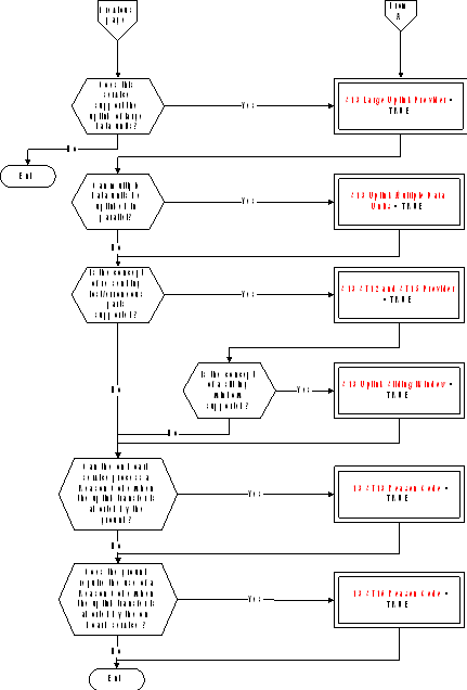 Figure A-12: Tailoring choices for the large data transfer service (View 2)#### Service requests and reports
Transferring the first part of a service data unit
(S13 Large Downlink Provider = TRUE): The telemetry report to downlink (Type = 13, Subtype = 1) the first part of a large service data unit is:
|
|
Large Data Unit ID |
Sequence Number |
Service Data Unit Part |
|
|||
|
|
S13 Large Data Unit ID |
S13 Sequence Number |
Fixed Octet String |
|
|||
|
|
S13 Downlink Multiple Data Units = TRUE |
|
|
|
|||
(S13 Large Uplink Provider = TRUE): The telecommand to uplink (Type = 13, Subtype = 9) the first part of a large service data unit is:
|
|
Large Data Unit ID |
Sequence Number |
Service Data Unit Part |
|
|||||||
|
|
S13 Large Data Unit ID |
S13 Sequence Number |
Fixed Octet String |
|
|||||||
|
|
S13 Uplink Multiple Data Units = TRUE |
|
|
|
|||||||
Transferring an intermediate part of a service data unit
(S13 Large Downlink Provider = TRUE): The telemetry report to downlink (Type = 13, Subtype = 3) an intermediate part of a large service data unit is the same as for (Type 13, Subtype 1).
(S13 Large Uplink Provider = TRUE): The telecommand to uplink (Type = 13, Subtype = 10) an intermediate part of a large service data unit is the same as for (Type 13, Subtype 9).
Transferring the last part of a service data unit
(S13 Large Downlink Provider = TRUE): The telemetry report to downlink (Type = 13, Subtype = 3) the last part of a large service data unit is the same as for (Type 13, Subtype 1) but with possibly fewer octets.
(S13 Large Uplink Provider = TRUE): The telecommand to uplink (Type = 13, Subtype = 10) the last part of a large service data unit is the same as for (Type 13, Subtype 9) but with possibly fewer octets.
Re-transferring a part of a service data unit
(S13 Large Downlink Provider = TRUE and S13 ST6 and ST7 Provider = TRUE): The telemetry report to re-downlink (Type = 13, Subtype = 7) a part of a large service data unit whose retransmission has been requested by the ground is the same as for (Type 13, Subtype 1) or (Type 13, Subtype 3).
(S13 Large Uplink Provider = TRUE and S13 ST12 and ST15 Provider = TRUE): The telecommand to re-uplink (Type = 13, Subtype = 12) a part of a large service data unit whose retransmission has been requested by the on-board service is the same as for (Type 13, Subtype 9) or (Type 13, Subtype 10).
Transfer abort initiated by the sending end
(S13 Large Downlink Provider = TRUE): The telemetry report (Type = 13, Subtype = 4) to notify a transfer abort initiated by the on-board service is:
|
|
Large Data Unit ID |
Reason Code |
|
||
|
|
S13 Large Data Unit ID |
S13 Reason Code |
|
||
|
|
S13 Downlink Multiple Data Units = TRUE |
S13 ST4 Reason Code = TRUE |
|
||
(S13 Large Uplink Provider = TRUE): The telecommand (Type = 13, Subtype = 13) to notify a transfer abort initiated by the ground is:
|
|
Large Data Unit ID |
Reason Code |
|
||
|
|
S13 Large Data Unit ID |
S13 Reason Code |
|
||
|
|
S13 Uplink Multiple Data Units = TRUE |
S13 ST13 Reason Code = TRUE |
|
||
Acknowledging the successful reception up to a part
(S13 Large Uplink Provider = TRUE): The telemetry report (Type = 13, Subtype = 14) to acknowledge the successful reception of the large service data unit up to a specified part is:
|
|
Large Data Unit ID |
Sequence Number |
|
||
|
|
S13 Large Data Unit ID |
S13 Sequence Number |
|
||
|
|
S13 Uplink Multiple Data Units = TRUE |
|
|
||
(S13 Large Downlink Provider = TRUE): The telecommand (Type = 13, Subtype = 5) to acknowledge the successful reception of the large service data unit up to a specified part is:
|
|
Large Data Unit ID |
Sequence Number |
|
||
|
|
S13 Large Data Unit ID |
S13 Sequence Number |
|
||
|
|
S13 Downlink Multiple Data Units = TRUE |
|
|
||
Notifying which parts have not been properly received
(S13 Large Uplink Provider = TRUE and S13 ST12 and ST15 Provider = TRUE): The telemetry report (Type = 13, Subtype = 15) to notify the ground that specified parts were not received or were erroneously received is:
|
|
|
|

|
|
||||
|
|
Large Data Unit ID |
N |
Sequence Number |
|
||||
|
|
S13 Large Data Unit ID |
S13 N |
S13 Sequence Number |
|
||||
|
|
S13 Uplink Multiple Data Units = TRUE |
|
|
|
||||
(S13 Large Downlink Provider = TRUE and S13 ST6 and ST7 Provider = TRUE): The telecommand (Type = 13, Subtype = 6) to notify the on-board sending sub-service that specified parts were not received or were erroneously received is:
|
|
|
|

|
|
||||
|
|
Large Data Unit ID |
N |
Sequence Number |
|
||||
|
|
S13 Large Data Unit ID |
S13 N |
S13 Sequence Number |
|
||||
|
|
S13 Downlink Multiple Data Units = TRUE |
|
|
|
||||
Transfer abort initiated by the receiving end
(S13 Large Uplink Provider = TRUE): The telemetry report (Type = 13, Subtype = 16) is:
|
|
Large Data Unit ID |
Reason Code |
|
|
|
S13 Large Data Unit ID |
S13 Reason Code |
|
|
|
S13 Uplink Multiple Data Units = TRUE |
S13 ST16 Reason Code = TRUE |
|
(S13 Large Downlink Provider = TRUE): The telecommand (Type = 13, Subtype = 8) is:
|
|
Large Data Unit ID |
Reason Code |
|
|
|
S13 Large Data Unit ID |
S13 Reason Code |
|
|
|
S13 Downlink Multiple Data Units = TRUE |
S13 ST8 Reason Code = TRUE |
|
Packet forwarding control service
The PUS service model
This service provides the means to control which packets are enabled for forwarding to ground at any given time. The minimum capability is for the ground to specify which packets are to be enabled (or disabled) by type and subtype. More complex service implementations enable:
the ground to request specific housekeeping, diagnostic or event report packets to be enabled or disabled;
the ground to request the service to report the list of currently enabled packets.
The service can either be provided by the application process that generates the packets concerned or by a centralised application process that is responsible for routing packets on the downlink.
Service tailoring data
The tailoring choices available for the packet forwarding control service are shown in Figure A-13 (Views 1 and 2).
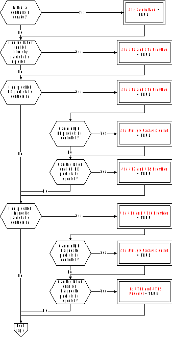 Figure: Tailoring choices for the packet forwarding control service (View 1)
 Figure A-13: Tailoring choices for the packet forwarding control service (View 2)#### Service requests and reports
Controlling the forwarding of specified telemetry source packets
The telecommands to enable (Type = 14, Subtype = 1) or disable (Type = 14, Subtype = 2) the forwarding of telemetry source packets of specified type and subtype are:
|
|
|

|
|
|||||||||
|
|
|
|
|

|
|
|||||||
|
|
|
|
|
|

|
|
||||||
|
|
N1 |
Application Process ID |
N2 |
Type |
N3 |
Subtype |
|
|||||
|
|
S14 N |
S14 APID |
S14 N |
S14 Type |
S14 N |
S14 Type |
|
|||||
|
|
S14 Centralised = TRUE |
|
|
|
|
|
||||||
Reporting the list of enabled telemetry source packets (S14 ST3 and ST4 Provider = TRUE)
The telecommand to report the list of telemetry source packet types and subtypes from the application process with an “Enabled” forwarding status (Type = 14, Subtype = 3) has no application data.
The corresponding telemetry report (Type = 14, Subtype = 4) is:
|
|
|

|
|
|||||||||
|
|
|
|
|

|
|
|||||||
|
|
|
|
|
|

|
|
||||||
|
|
N1 |
Application Process ID |
N2 |
Type |
N3 |
Subtype |
|
|||||
|
|
S14 N |
S14 APID |
S14 N |
S14 Type |
S14 N |
S14 Type |
|
|||||
|
|
S14 Centralised = TRUE |
|
|
|
|
|
||||||
Controlling the forwarding of specified housekeeping packets (S14 ST5 and ST6 Provider = TRUE)
The telecommands to enable (Type = 14, Subtype = 5) and disable (Type = 14, Subtype = 6) forwarding of selected housekeeping packets are:
|
|
|

|
|
|||||||
|
|
|
|
|

|
|
|||||
|
|
N1 |
Application Process ID |
N2 |
SID |
|
|||||
|
|
S14 N |
S14 APID |
S14 N |
S14 SID |
|
|||||
|
|
S14 Centralised = TRUE and S14 Multiple Packet Control = TRUE |
S14 Centralised = TRUE |
S14 Multiple Packet Control = TRUE |
|
|
|||||
Reporting the list of enabled housekeeping packets (S14 ST7 and ST8 Provider = TRUE)
The telecommand to report the list of housekeeping report identifiers with an “Enabled” forwarding status (Type = 14, Subtype = 7) has no application data.
The corresponding telemetry report of enabled housekeeping report identifiers (Type = 14, Subtype = 8) is:
|
|
|

|
|
|||||||
|
|
|
|
|

|
|
|||||
|
|
N1 |
Application Process ID |
N2 |
SID |
|
|||||
|
|
S14 N |
S14 APID |
S14 N |
S14 SID |
|
|||||
Controlling the forwarding of specified diagnostic packets (S14 ST9 and ST10 Provider = TRUE)
The telecommands to enable (Type = 14, Subtype = 9) and disable (Type = 14, Subtype = 10) forwarding of selected diagnostic packets are:
|
|
|

|
|
|||||||
|
|
|
|
|

|
|
|||||
|
|
N1 |
Application Process ID |
N2 |
SID |
|
|||||
|
|
S14 N |
S14 APID |
S14 N |
S14 SID |
|
|||||
|
|
S14 Centralised = TRUE and S14 Multiple Packet Control = TRUE |
S14 Centralised = TRUE |
S14 Multiple Packet Control = TRUE |
|
|
|||||
Reporting the list of enabled diagnostic packets (S14 ST11 and ST12 Provider = TRUE)
The telecommand to report the list of diagnostic report identifiers with an “Enabled” forwarding status (Type = 14, Subtype = 11) has no application data.
The corresponding telemetry report of enabled diagnostic report identifiers (Type = 14, Subtype = 12) is:
|
|
|

|
|
|||||||
|
|
|
|
|

|
|
|||||
|
|
N1 |
Application Process ID |
N2 |
SID |
|
|||||
|
|
S14 N |
S14 APID |
S14 N |
S14 SID |
|
|||||
Controlling the forwarding of specified event report packets (S14 ST13 and ST14 Provider = TRUE)
The telecommands to enable (Type = 14, Subtype = 13) and disable (Type = 14, Subtype = 14) forwarding of selected event report packets are:
|
|
|

|
|
|||||||
|
|
|
|
|

|
|
|||||
|
|
N1 |
Application Process ID |
N2 |
RID |
|
|||||
|
|
S14 N |
S14 APID |
S14 N |
S14 RID |
|
|||||
|
|
S14 Centralised = TRUE and S14 Multiple Packet Control = TRUE |
S14 Centralised = TRUE |
S14 Multiple Packet Control = TRUE |
|
|
|||||
Reporting the list of enabled event report packets (S14 ST15 and ST16 Provider = TRUE)
The telecommand to report the list of event report identifiers with an “Enabled” forwarding status (Type = 14, Subtype = 15) has no application data.
The corresponding telemetry report of enabled event report identifiers (Type = 14, Subtype = 16) is:
|
|
|

|
|
|||||||
|
|
|
|
|

|
|
|||||
|
|
N1 |
Application Process ID |
N2 |
RID |
|
|||||
|
|
S14 N |
S14 APID |
S14 N |
S14 RID |
|
|||||
On-board storage and retrieval service
The PUS service model
This is a supporting service that provides the capability to selectively store telemetry packets on-board for subsequent retrieval and downlink on request from the ground. There are two sub-services defined, viz.:
the packet selection sub-service which is responsible for selecting which packets shall be sent for on-board storage;
the packet storage and retrieval sub-service which is responsible for managing the packet store(s) and the subsequent retrieval and downlink of packets requested from ground.
Two possible implementations are supported. In the centralised option, a single application process provides both of these sub-services. In the decentralised option, the sub-services are provided by different on-board application processes.
Two types of packet store are foreseen, circular and bounded. When a circular packet store is full, any subsequently received packet over-writes the oldest packet in the store. When a bounded packet store is full, any subsequently received packet is ignored. The contents of a bounded packet store are explicitly deleted by ground to free up storage space and enable the resumption of storage of newly arriving packets.
Retrieved packets can be downlinked:
in the same VC as real-time packets, in which case they are wrapped in packet containers belonging to the on-board storage and retrieval service;
in a VC dedicated for retrieval purposes, in which case the packets are downlinked exactly as they were originally received by the store.
Optional extensions to the service include:
capabilities to modify the packet storage selection and to report the current selection to the ground on request;
the capability to retrieve by specifying a time range or a packet range;
the capability to maintain a catalogue of the contents of a store and to report the catalogue to the ground on request.
Service tailoring data
The tailoring choices available for the on-board storage and retrieval service are shown in Figure A-14 (Views 1 to 3).
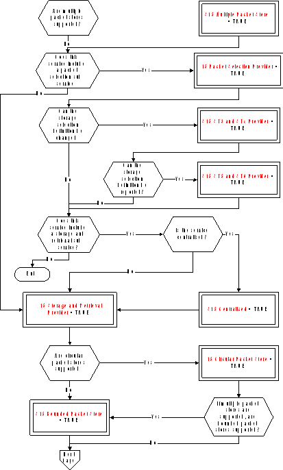 Figure: Tailoring choices for the on-board storage and retrieval service (View 1)
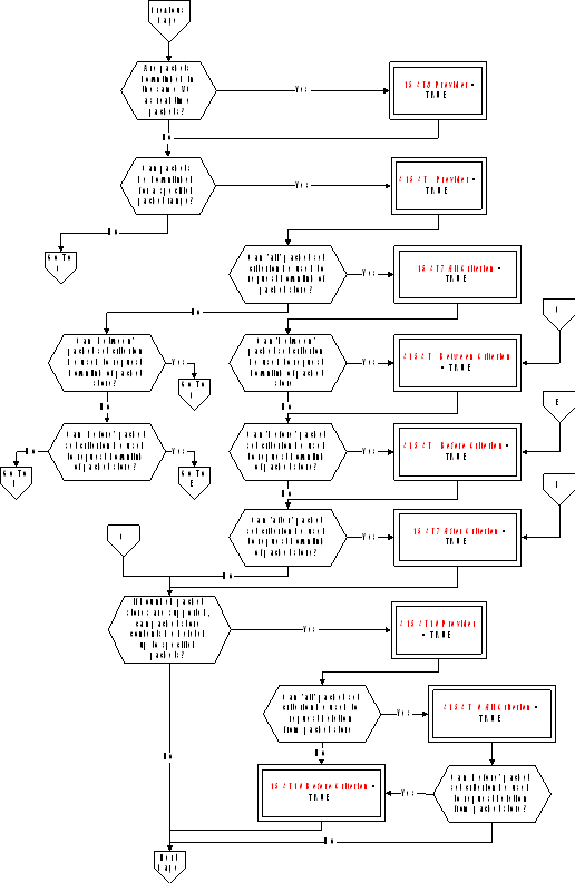 Figure A-14: Tailoring choices for the on-board storage and retrieval service (View 2)
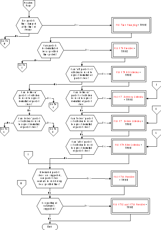 Figure A-14: Tailoring choices for the on-board storage and retrieval service (View 3)#### Service requests and reports
Controlling the storage in specified packet stores (S15 Packet Selection Provider = TRUE)
The telecommands to enable (Type = 15, Subtype = 1) and disable (Type = 15, Subtype = 2) storage in specified packet stores are:
|
|
|

|
|
|
|
|
N |
Store ID |
|
|
|
|
S15 N |
S15 Store ID |
|
|
|
|
S15 Multiple Packet Stores = TRUE |
|
|
|
Modifying the definition of a storage selection criteria (S15 Packet Selection Provider = TRUE and S15 ST3 and ST4 Provider = TRUE)
The telecommand to add (Type = 15, Subtype = 3) and remove (Type = 15, Subtype = 4) packet types and subtypes to/from the storage selection definition for a specified packet store are:
|
|
|

|
|
||||||||||
|
|
|
|
|
|

|
|
|||||||
|
|
|
|
|
|
|

|
|
||||||
|
|
Store ID |
N1 |
Application Process ID |
N2 |
Type |
N3 |
Subtype |
|
|||||
|
|
S15 Store ID |
S15 N |
S15 N |
S15 N |
S15 Type |
S15 N |
S15 Type |
|
|||||
|
|
S15 Multiple Packet Stores = TRUE |
S15 Centralised = TRUE |
|
|
|
|
|
||||||
Reporting a storage selection definition (S15 Packet Selection Provider = TRUE and S15 ST3 and ST4 Provider = TRUE and S15 ST5 and ST6 Provider = TRUE)
The telecommand to report a storage selection definition (Type = 15, Subtype = 5) is:
|
|
Store ID |
|
|
|
S15 Store ID |
|
|
|
S15 Multiple Packet Stores = TRUE |
|
The corresponding telemetry report (Type = 15, Subtype = 6) is
|
|
|

|
|
||||||||||
|
|
|
|
|
|

|
|
|||||||
|
|
|
|
|
|
|

|
|
||||||
|
|
Store ID |
N1 |
Application Process ID |
N2 |
Type |
N3 |
Subtype |
|
|||||
|
|
S15 Store ID |
S15 N |
S15 APID |
S15 N |
S15 Type |
S15 N |
S15 Type |
|
|||||
|
|
S15 Multiple Packet Stores = TRUE |
S15 Centralised = TRUE |
|
|
|
|
|
||||||
Downlinking the contents of a packet store for a specified packet range (S15 Storage and Retrieval Provider = TRUE and S15 ST7 Provider = TRUE)
The telecommand to downlink the contents of a packet store for a specified packet range (Type = 15, Subtype = 7) is:
|
|
Store ID |
Packet Set |
Application Process ID 1 |
Source Sequence Count 1 |
Application Process ID 2 |
Source Sequence Count 2 |
|
|
|
S15 Store ID |
S15 Packet Set |
S15 APID |
S15 Source Sequence Count |
S15 APID |
S15 Source Sequence Count |
|
|
|
S15 Multiple Packet Stores = TRUE |
Condition 1 (see below) |

|

|
|
||
Condition 1 = If only one of the variables (S15 ST7 All Criterion, S15 ST7 Between Criterion, S15 ST7 Before Criterion, S15 ST7 After Criterion) has the value = TRUE
If packets are downlinked in the same Virtual Channel as real-time packets (S15 ST8 Provider = TRUE), the corresponding telemetry report of the packet store contents (Type = 15, Subtype = 8) is:
|
|
|

|
|
|
|
|
N |
TLM Packet |
|
|
|
|
S15 N |
Any TM |
|
|
Downlinking the contents of a packet store for a specified time period (S15 Storage and Retrieval Provider = TRUE and S15 Time Stamping = TRUE and S15 ST9 Provider = TRUE)
The telecommand to downlink the contents of a packet store for a specified time period (Type = 15, Subtype = 9) is:
|
|
Store ID |
Time Span |
Storage Time 1 |
Storage Time 2 |
|
|
|
S15 Store ID |
S15 Time Span |
S15 Time |
S15 Time |
|
|
|
S15 Multiple Packet Stores = TRUE |
Condition 2 (see below) |
Time Span = Between, Before or After |
Time Span = Between |
|
Condition 2 = If only one of the variables (S15 ST9 All Criterion, S15 ST9 Between Criterion, S15 ST9 Before Criterion, S15 ST9 After Criterion) has the value = TRUE
Deleting the contents of specified packet stores up to specified packets (S15 Storage and Retrieval Provider = TRUE and S15 ST10 Provider = TRUE)
The telecommand to delete the contents of specified packet stores up to specified packets (Type = 15, Subtype = 10) is:
|
|
|
|

|
|
|||||||
|
|
Deletion Set |
N |
Store ID |
Application Process ID |
Source Sequence Count |
|
|||||
|
|
S15 Packet Set |
S15 N |
S15 Store ID |
S15 APID |
S15 Source Sequence Count |
|
|||||
|
|
Condition 3 (see below) |
|

|
|
|||||||
Condition 3 = If only one of the variables (S15 ST10 All Criterion, S15 ST10 Before Criterion) has the value = TRUE
Deleting the contents of specified packet stores up to a specified storage time (S15 Storage and Retrieval Provider = TRUE and S15 ST11 Provider = TRUE)
The telecommand to delete the contents of specified packet stores up to a specified storage time (Type = 15, Subtype =11) is:
|
|
|
|

|
|
||||
|
|
End Time |
N |
Store ID |
|
||||
|
|
S15 Time |
S15 N |
S15 Store ID |
|
||||
|
|
|
S15 Multiple Packet Stores = TRUE |
|
|
||||
Reporting packet store catalogues (S15 Storage and Retrieval Provider = TRUE and S15 ST12 and ST13 Provider = TRUE)
The telecommand to report the catalogues of selected packet stores (Type = 15, Subtype = 12) is:
|
|
|

|
|
|
|
|
N |
Store ID |
|
|
|
|
S15 N |
S15 Store ID |
|
|
|
|
S15 Multiple Packet Stores = TRUE |
|
|
|
The corresponding telemetry report of packet store catalogues (Type = 15, Subtype = 13) is:
|
|
|

|
||||||||||
|
|
N |
Store ID |
Application Process ID 1 |
Source Sequence Count 1 |
Service Type1 |
Service Subtype1 |
|
|||||
|
|
S15 N |
S15 Store ID |
S15 APID |
S15 Source Sequence Count |
S15 Type |
S15 Type |
|
|||||
|
|
S15 Multiple Packet Stores = TRUE |
|
|
|
|
|
||||||
|

|
||||||||||||
|
|
Packet Sub- counter1 |
Storage Time 1 |
Application Process ID 2 |
Source Sequence Count 2 |
Service Type2 |
Service Subtype2 |
|
|||||
|
|
S15 Packet Subcounter |
S15 Time |
S15 APID |
S15 Source Sequence Count |
S15 Type |
S15 Type |
|
|||||
|
|
Optional |
S15 Time Stamping = TRUE |
|
|
|
|
|
|||||
|

|
|
|||||||||||
|
|
Packet Sub-counter2 |
Storage Time 2 |
Percentage Filled |
Percentage Downlinked |
No. of Packets Stored |
No. of Packets Downlinked |
|
|||||
|
|
S15 Packet Subcounter |
S15 Time |
S15 Percent |
S15 Percent |
S15 No Of Packets |
S15 No Of Packets |
|
|||||
|
|
Optional |
S15 Time Stamping = TRUE |
|
|
|
|
|
|||||
Test service
The PUS service model
The test service provides the capability to exercise in-built test functions and to report the results to the ground. It is envisaged that the majority of such test functions are mission-specific in nature. The only generic test identified in the PUS is an end-to-end connection test. This consists of a test request sent from the ground, as a result of which the on-board test service generates a standard test report. This serves to confirm that the uplink and downlink routes are operational and that the application process is alive and capable of performing basic functions including telecommand processing and telemetry packet generation.
Service tailoring data
There are no tailoring choices available for this service.
Service requests and reports
The telecommand to perform an end-to-end connection test (Type = 17, Subtype = 1) has no application data.
The corresponding connection test report (Type = 17, Subtype = 2) has no Source Data.
On-board operations procedure service
The PUS service model
This service provides the capability for the ground to load operational procedures on-board and to control their subsequent execution. The minimum implementation of the service enables the ground to load a procedure, delete a procedure, start, stop, suspend and resume a procedure.
A procedure can comprise a number of distinct self-contained steps and the suspend operation can specify a step number at which the procedure shall be “held”; similarly the resume operation can indicate the step from which the procedure execution shall be re-started.
Extensions to the service implementation enable:
parameters to be supplied to the procedure whilst it is running;
the reporting of the list of procedures loaded on-board and the list of currently active procedures;
Service tailoring data
The tailoring choices available for the on-board operations procedure service are shown in Figure A-15.
 Figure: Tailoring choices for the on-board operations procedure service
Service requests and reports
Loading a procedure
The telecommand to load a procedure (Type = 18, Subtype = 1) is:
|
|
Procedure ID |
Length |
Procedure Code |
|
|
|
S18 Procedure ID |
Variable Octet String |
|
|
Deleting a procedure
The telecommand to delete a procedure (Type = 18, Subtype = 2) is:
|
|
Procedure ID |
|
|
|
S18 Procedure ID |
|
Starting a procedure
There are two possibilities for the telecommand to start a procedure (Type = 18, Subtype = 3). Where the full set of parameters is always provided (or where the procedure has no parameters), the telecommand is:
|
|
|

|
|
|
|
|
Procedure ID |
Parameters |
|
|
|
|
S18 Procedure ID |
Any |
|
|
|
|
|

|
|
|
Where a variable number of parameters can be supplied (S18 Parameter Subset = TRUE), the telecommand is:
|
|
|
|

|
|
||||||
|
|
Procedure ID |
N |
Parameter# |
Value |
|
|||||
|
|
S18 Procedure ID |
S18 N |
S18 Parameter Number |
Deduced |
|
|||||
Stopping a procedure
The telecommand to stop a procedure (Type = 18, Subtype = 4) is:
|
|
Procedure ID |
Step ID |
|
|
|
S18 Procedure ID |
S18 Step ID |
|
|
|
|

|
|
Suspend a procedure
The telecommand to suspend a procedure (Type = 18, Subtype = 5) is:
|
|
Procedure ID |
Step ID |
|
|
|
S18 Procedure ID |
S18 Step ID |
|
|
|
|

|
|
Resume a procedure
The telecommand to resume a procedure (Type = 18, Subtype = 6) is:
|
|
Procedure ID |
Step ID |
|
|
|
S18 Procedure ID |
S18 Step ID |
|
|
|
|

|
|
Abort a procedure
The telecommand to abort a procedure (Type = 18, Subtype = 12) is:
|
|
Procedure ID |
|
|
|
S18 Procedure ID |
|
Communicate parameters to a procedure (S18 ST7 Provider = TRUE)
There are two possibilities for the telecommand to communicate parameters to a procedure (Type = 18, Subtype =7). Where the full set of parameters is always provided (or where the procedure has no parameters), the telecommand is:
|
|
|

|
|
|
|
|
Procedure ID |
Parameters |
|
|
|
|
S18 Procedure ID |
Any |
|
|
|
|
|

|
|
|
Where a variable number of parameters can be supplied (S18 Parameter Subset = TRUE), the telecommand is:
|
|
|
|

|
|
||||||
|
|
Procedure ID |
N |
Parameter# |
Value |
|
|||||
|
|
S18 Procedure ID |
S18 N |
S18 Parameter Number |
Deduced |
|
|||||
Reporting the list of on-board operations procedures (S18 ST8 and ST9 Provider = TRUE)
The telecommand to report the list of on-board operations procedures (Type = 18, Subtype = 8) has no application data.
The corresponding telemetry report (Type = 18, Subtype = 9) is:
|
|
|

|
|
|
|
|
NPROC |
Procedure ID |
|
|
|
|
S18 NProc |
S18 Procedure ID |
|
|
Reporting the list of active on-board operations procedures (S18 ST10 and ST11 Provider = TRUE)
The telecommand to report the list of active on-board operations procedures (Type = 18, Subtype = 10) has no application data.
The corresponding telemetry report (Type = 18, Subtype = 11) is:
|
|
|

|
|
|||||||
|
|
NPROC |
Procedure ID |
Status |
Step ID |
|
|||||
|
|
S18 NProc |
S18 Procedure ID |
S18 Status |
S18 Step ID |
|
|||||
Event/action service
The PUS service model
The event/action service enables the definition of an on-board action to be implemented when a specified on-board event is detected. In the PUS service model, the event is limited to the receipt of a given event report packet (see Annex A.6) and the associated action is limited to the issuing of a telecommand.
The ground can add event/action couplets to the on-board list and can also delete event/action couplets or clear the list altogether.
Optional extensions to the service enable:
individual actions to be enabled or disabled (whilst the associated event remains nevertheless in the on-board list);
reporting of the current content of the on-board list on ground request.
Service tailoring data
The tailoring choices available for the event/action service are shown in Figure A-16.
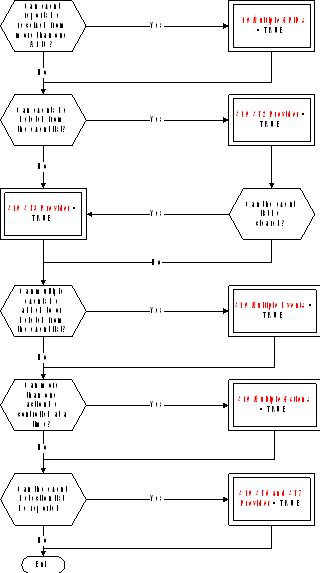 FigureTailoring choices for the event/action service
Service requests and reports
Adding events to the detection list
The telecommand to add events to the detection list (Type = 19, Subtype = 1) is:
|
|
|

|
|
|||||||
|
|
N |
Application Process ID |
RID |
Telecommand Packet |
|
|||||
|
|
S19 N |
S19 APID |
S19 RID |
Any TC |
|
|||||
|
|
S19 Multiple Events = TRUE |
S19 Multiple APIDs = TRUE |
|
|
|
|||||
Deleting events from the detection list (S19 ST2 Provider = TRUE)
The telecommand to delete events from the detection list (Type = 19, Subtype = 2) is:
|
|
|

|
|
|||||
|
|
N |
Application Process ID |
RID |
|
||||
|
|
S19 N |
S19 APID |
S19 RID |
|
||||
|
|
S19 Multiple Events = TRUE |
S19 Multiple APIDs = TRUE |
|
|
||||
Clearing the event detection list (S19 ST3 Provider= TRUE)
The telecommand to clear the event detection list (Type = 19, Subtype = 3) has no application data.
Controlling the actions associated with events
The telecommands to enable actions (Type = 19, Subtype = 4) and to disable actions (Type = 19, Subtype = 5) are:
|
|
|

|
|
|||||
|
|
N |
Application Process ID |
RID |
|
||||
|
|
S19 N |
S19 APID |
S19 RID |
|
||||
|
|
S19 Multiple Actions = TRUE |
S19 Multiple APIDs = TRUE |
|
|
||||
Reporting the event detection list (S19 ST6 and ST7 Provider = TRUE)
The telecommand to report the event detection list (Type = 19, Subtype = 6) has no application data.
The corresponding telemetry report (Type = 19, Subtype = 7) is:
|
|
|

|
|
|||||||
|
|
N |
Application Process ID |
RID |
Action Status |
|
|||||
|
|
S19 N |
S19 APID |
S19 RID |
S19 Status |
|
|||||
|
|
|
S19 Multiple APIDs = TRUE |
|
|
|
|||||
ANNEX(informative)Data type definitions
Conventions
In this annex, the ISO extended Backus-Naur form (EBNF) is used as an alternative convention to specify the syntax of data types and language constructs. The complete specification of ISO EBNF is given in ISO/IEC 14977: 1996 (E), but the salient features of the convention are summarised below.
Each syntax rule consists of a non-terminal symbol and an EBNF expression separated by an equal sign (=) and terminated with a semicolon (;) e.g.:
Integer Constant = Sign, { Digit }- ;
The right-hand side of the rule is the definition of the non-terminal symbol on the left-hand side.
The EBNF expression consists of terminal symbols, non-terminal symbols and connective symbols as defined in Table B-1, separated by a “,”.
A terminal symbol is a sequence of one or more characters forming an irreducible element. A terminal symbol may consist of one or more words separated by one or more separators. The space, tab and end-of-line characters are separators.
Non-printing characters such as space, tab and end-of-line have no formal effect on the syntax as long as they appear outside of a terminal symbol.
TableEBNF symbols and meanings
|
Symbol
|
Meaning
|
|
X | Y
|
One of X or Y (exclusive or)
|
|
[ X ]
|
Zero or one occurrence of X
|
|
{ X }
|
Zero or more occurrences of X
|
|
{ X }-
|
One or more occurrences of X
|
|
n * X
|
A repetition of X exactly n times
|
|
( X, Y )
|
Grouping construct
|
|
"Text"
|
Terminal symbol (text between double quotes representing a keyword). If a double quote is used inside the text, the text is enclosed instead by single quotes.
|
-
1 E.g.: If Statement = "if", Expression, "then", {Statement, ";"}-, ["else", {Statement, ";"}-], "end if";
means that a set of one or more statements, each followed by a ";" appears after the "then" part of the definition. The part of the definition within the square brackets (the "else" part) is optional, but if present occurs once only in the “if statement”. -
2 E.g.: Integer Constant = [ Sign ], { Digit }- , [? Engineering Units ?];
means that an integer constant is defined as an optional sign (a plus or a minus) followed by a sequence of one or more digits, followed by an optional engineering units.
Comments
Comments may be inserted anywhere within the script of a complex data type and have no effect on the execution of the script.
Comments begin and end with the character pair symbols "/" and "/" respectively.
Data types and data items
Definitions
Data types and data items are defined in clause 5.
EBNF Representation
|
Absolute Time =
|
|
Absolute Time Constant =
|
|
Activity Reference =
|
|
Argument Reference =
|
|
Binary Digit =
|
|
Binary Symbol =
|
|
Bit String =
|
|
Bit String Constant =
|
|
Boolean =
|
|
Boolean Constant =
|
|
Character =
|
|
Character String =
|
|
Character String Constant =
|
|
Complex Data Type =
|
|
Complex Data Type Constant =
|
|
Data Type =
|
|
Data Value =
|
|
Day =
|
|
Day Of Month =
|
|
Days =
|
|
Digit =
|
|
Entity Type =
|
|
Entity Type Reference =
|
|
Enumerated Constant =
|
|
Event Reference =
|
|
Fraction Of Second =
|
|
Hexadecimal Constant =
|
|
Hexadecimal Digit =
|
|
Hexadecimal Symbol =
|
|
Hour =
|
|
Hours =
|
|
Identifier =
|
|
Identifier First Word =
|
|
Identifier Subsequent Word =
|
|
Integer =
|
|
Integer Constant =
|
|
Letter =
|
|
Minute =
|
|
Minutes =
|
|
Month =
|
|
Name =
|
|
Object Reference =
|
|
Octet String =
|
|
Octet String Constant =
|
|
PC =
|
|
PFC =
|
|
PFC Constant =
|
|
Product Reference =
|
|
PTC =
|
|
PTC Constant =
|
|
PUS Data Type =
|
|
Real =
|
|
Real Constant =
|
|
Relative Time =
|
|
Relative Time Constant =
|
|
Reporting Data Reference =
|
|
Second =
|
|
Seconds =
|
|
Service Subtype =
|
|
Service Subtype Constant =
|
|
Service Type =
|
|
Service Type Constant =
|
|
Sign =
|
|
Simple Data Type =
|
|
System Element Reference =
|
|
Unsigned Integer =
|
|
Unsigned Integer Constant =
|
|
User Defined Enumerated Type =
|
|
User Defined Enumerated Type Reference =
|
|
Value Type =
|
|
Value Type Data Type =
|
|
Value Type Set =
|
|
Year =
|
Activity Call
The use of Activity Call ensures conformance with the activity call requirements given in clause 6.2.2.
The syntax for defining constants of type Activity Call is specified in Annex A.3.9.28 of ECSSEST-7032.
EXPL - Expression Language
Definitions
The use of EXPL ensures conformance with the expression requirements given in clause 6.2.3.
The syntax for defining constants of type EXPL (i.e. Expression Language Expression Definition) is the following:
![]()


![]()

 where:
Table 6 of ECSSEST-7032 defines, for each operator, the types that can be used for the operands.
Boolean Operator is one of the symbols {"AND", "OR", "XOR"}.
Addition Operator is one of the characters {"+", "-"}.
Relational Operator is one of the symbols {"AND", "OR", "XOR"}.
Multiplication Operator is one of the characters {"*", "/"}.
Sign is one of the characters {"+", "-"}.
Negation Boolean Operator is the symbol "NOT".
Function is one of the functions defined in ECSS-E-ST-70-32 Annex C.
Object Reference, Boolean Constant, Integer Constant, Real Constant, Character String Constant, Absolute Time Constant, Relative Time Constant and Simple Data Type are as defined in clauses 5.4 and 5.5.
EBNF Representation
|
Addition Operator =
|
|
Boolean Operator =
|
|
Comparative Expression =
|
|
Constant = Object Reference
|
|
Expression = Relational Expression, [Boolean Operator, Expression]; |
|
Expression Language Expression Definition = Expression; |
|
Factor =
|
|
Function =
|
|
Multiplication Operator =
|
|
Negation Boolean Operator =
|
|
Product =
|
|
Relational Expression =
|
|
Relational Operator =
|
|
Sign =
|
|
Simple Factor = Constant
|
|
Term =
|
IFL - Interpretation Function Language
Definition
The use of IFL ensures conformance with the requirements given in clause 6.2.4.
The syntax for defining constants of type IFL (i.e. Interpretation Function Language Expression Definition) is the following:


![]()
 where:
Table 6 of ECSSEST-7032 defines, for each operator, the types that can be used for the operands.
Boolean Operator is one of the symbols {"AND", "OR", "XOR"}.
Addition Operator is one of the characters {"+", "-"}.
Relational Operator is one of the symbols {"AND", "OR", "XOR"}.
Multiplication Operator is one of the characters {"*", "/"}.
Sign is one of the characters {"+", "-"}.
Negation Boolean Operator is the symbol "NOT".
Function is one of the functions defined in ECSS-E-ST-70-32 Annex C.
Object Reference, Boolean Constant, Integer Constant, Real Constant, Character String Constant, Absolute Time Constant, Relative Time Constant and Simple Data Type are as defined in clauses 5.4 and 5.5.
EBNF Representation
|
Addition Operator =
|
|
Boolean Operator =
|
|
Comparative Expression =
|
|
Constant = Object Reference
|
|
Expression = Relational Expression, [Boolean Operator, Expression]; |
|
Factor =
|
|
Function =
|
|
Interpretation Function Language Expression Definition = Expression; |
|
Multiplication Operator =
|
|
Negation Boolean Operator =
|
|
Product =
|
|
Relational Expression =
|
|
Relational Operator =
|
|
Sign =
|
|
Simple Factor = Constant
|
|
Term =
|
SPEL - Synthetic Parameter Expression Language
Definitions
The use of SPEL ensures conformance with the requirements given in clause 6.2.6.
The syntax for defining constants of type SPEL (i.e. Synthetic Parameter Expression Definition) is the following:
 where:
Trigger Body defines the conditions under which the calculation is executed.
Declaration Body declares the local variables used for the calculation.
Main Body contains the statements that perform the synthetic parameter calculation.


![]() where:
where:
Variable Declaration declares the local variables used for the synthetic parameter calculation.
Persistent Variable Declaration are those variables that maintain their values from one synthetic parameter calculation to the next (Example: A synthetic parameter that uses the delta between the current value and the previous value of a given parameter).
Simple Data Type is one of the simple data types defined in clause 5.5.2.

 where:
Set Context Statement defines the context in which the related set of statement executes.
Assignment Statement assigns a value to a local variable.
Flow Control Statement controls the execution flow through the main body.
Synthetic Parameter Assignment Statement assigns the engineering value of the synthetic parameter or of one of its components.
 where Set Context Statement defines the context in which a set of statements executes, i.e. a system element or a reporting data context identified by the Object Reference.
![]() where Assignment Statement assigns the value of a local variable.
where Assignment Statement assigns the value of a local variable.


 where:
The Case Statement works in the following way:
If the value of the "in case" expression corresponds to the value of one of the case tags then the corresponding statement (or set of statements) is executed.
If the value of the "in case" expression does not correspond to any of the values of the case tags, and if there is an "otherwise" case tag, then the corresponding statement (or set of statements), and only that one, is executed.
Otherwise, no statement (or set of statements) is executed.
If two or more case tags have the same value only the first one is processed.
If the "in case" expression corresponds to the value of two or more case tags, only the first one is processed.
 where Synthetic Parameter Assignment Statement assigns the engineering value of a synthetic parameter or the engineering value of one of the components of a compound synthetic parameter.
 where Reporting Data Property Request obtains the requested property of the related reporting data. The standard properties that can be requested for a reporting data or a variable are defined in Table A-6 of ECSSEST-7032.
The following conventions apply:
Reference to a property of a reporting data alone implies the "get" request (e.g. “If Raw Value of Battery1 Voltage > 127, then….” implies that the raw value of the parameter Battery1 Voltage is “got”).
Reference to a parameter alone (i.e. no request and no property) implies the "get" Engineering Value request (e.g. “Wait until Elevation of Redu Prime Antenna < 5 deg …..” implies that the engineering value of the parameter Elevation of Redu Prime Antenna is “got”).

![]()
 where:
Table A-4 of ECSSEST-7032 defines, for each operator, the types that can be used for the operands.
Boolean Operator is one of the symbols {"AND", "OR", "XOR"}.
Addition Operator is one of the characters {"+", "-"}.
Relational Operator is one of the symbols {"AND", "OR", "XOR"}.
Multiplication Operator is one of the characters {"*", "/"}.
Sign is one of the characters {"+", "-"}.
Negation Boolean Operator is the symbol "NOT".
Function is one of the functions defined in ECSS-E-ST-70-32 Annex C or one of the bit-manipulation functions defined in Annex B.7.2.
Object Reference, Boolean Constant, Integer Constant, Real Constant, Character String Constant, Absolute Time Constant, Relative Time Constant and Simple Data Type are as defined in clauses 5.4 and 5.5.
Bit-manipulation functions
|
Name
|
Arguments Type
|
Result Type
|
Description
|
Example
|
|
bitand
|
integer (list of 2 arguments)
|
integer
|
Returns the bit wise and of the arguments.
|
bitand(7, 5) = 5
|
|
bitnot
|
integer
|
integer
|
Returns the bit wise negative of the argument.
|
bitnot(x)+1 = -x
|
|
bitor
|
integer (list of 2 arguments)
|
integer
|
Returns the bit wise or of the arguments.
|
bitor(7, 5) = 7
|
|
bitxor
|
integer (list of 2 arguments)
|
integer
|
Returns the bit wise exclusive or of the arguments.
|
bitxor(7, 5) = 2
|
|
bitshl
|
integer (list of 2 arguments)
|
integer
|
Returns the value of the first argument, shifted to the left by the number of bits given in the second argument.
|
bitshl(7, 1) = 14
|
|
bitshr
|
integer (list of 2 arguments)
|
integer
|
Returns the value of the first argument, shifted to the right by the number of bits given in the second argument.
|
bitshr(7, 1) = 3
|
EBNF Representation
|
Addition Operator =
|
|
Assignment Statement =
|
|
Boolean Operator =
|
|
Case Statement =
|
|
Case Tag =
|
|
Comparative Expression =
|
|
Constant = Object Reference
|
|
Declaration Body =
|
|
Description =
|
|
Expression = Relational Expression, [Boolean Operator, Expression]; |
|
Factor =
|
|
Flow Control Statement =
|
|
Function =
|
|
If Statement =
|
|
Main Body =
|
|
Multiplication Operator =
|
|
Negation Boolean Operator =
|
|
Persistent Variable Declaration =
|
|
Product =
|
|
Relational Expression =
|
|
Relational Operator =
|
|
Reporting Data Property Name =
|
|
Reporting Data Property Request =
|
|
Set Context Statement =
|
|
Sign =
|
|
Simple Data Type =
|
|
Simple Factor =
|
|
Statement =
|
|
Synthetic Parameter Assignment Statement =
|
|
Synthetic Parameter Expression Definition =
|
|
Term =
|
|
Trigger Body =
|
|
Variable Declaration =
|
|
Variable Reference =
|
PLUTO – Procedure Language
The use of PLUTO ensures conformance with the requirements given in clause 6.2.5.
The syntax for defining constants of type PLUTO (i.e. Procedure Definition is defined in Annex A of ECSSEST-7032.
VAL – Value Language
Definition
The use of VAL ensures conformance with the requirements given in clause 6.2.7.
The syntax for defining constants of type VAL (i.e. Value Set Definition) is the following:


 where:
Depending on whether the value set is related to arguments of an activity or to a reporting data, the Component Reference refers to:
an argument or a component of a compound argument, or
a reporting data or a component of a compound parameter.
Activity Call is a call to an activity as defined in Annex B.4.
Reporting Data Reference is a reference to a reporting data as defined in clause 5.5.
System Element Reference is a reference to a system element as defined in clause 5.5.
Object Reference, Boolean Constant, Integer Constant, Real Constant, Character String Constant, Absolute Time Constant, Relative Time Constant and Simple Data Type are as defined in clauses 5.4 and 5.5.
EBNF Representation
|
Array Value =
|
|
Component Reference =
|
|
Constant = Object Reference
|
|
Record Value =
|
|
Simple Value =
|
|
Value Set Definition =
|
Bibliography
|
ECSS-S-ST-00
|
ECSS system – Description, implementation and general requirements
|
|
ECSS-E-ST-10
|
Space engineering – System engineering – general requirements
|
|
ECSS-E-ST-50
|
Space engineering – Communications
|
|
ECSS-E-ST-50-03
|
Space engineering – Space data links – Telemetry transfer frame protocol
|
|
ECSS-M-ST-40
|
Space project management - Configuration and information management
|
|
CCSDS 102.0-B-5
|
Packet Telemetry, Blue Book, Issue 5, November 2000
|
|
CCSDS 201.0-B-3
|
Telecommand Part 1 - Channel Service, Blue Book, June 2000
|
|
CCSDS 202.0-B-3
|
Telecommand Part 2 - Data Routing Service, Blue Book, June 2001
|
|
CCSDS 202.1-B-2
|
Telecommand Part 2.1 - Command Operation Procedures, Blue Book, June 2001
|
|
CCSDS 203.0-B-2
|
Telecommand Part 3 - Data Management Service, Blue Book, June 2001
|
|
CCSDS 301.0-B-3
|
Time Code Formats, Blue Book, January 2002
|
|
CCSDS 727.0-b-2
|
CCSDS File Delivery Protocol (CFDP), Blue Book, Issue 2, October 2002
|
|
CCSDS 100.0-G-1
|
Telemetry: Summary of Concept and Rationale, Green Book, December 1987
|
|
CCSDS 200.0-G-6
|
Telecommand: Summary of Concept and Rationale, Green Book, January 1987
|
|
CCSDS A30.0-G-3
|
CCSDS Glossary, Green Book, July 1997
|
|
ESA-PSS-04-151
|
Telecommand decoder specification, Issue 1, September 1993
|
|
ISO/IEC 14977
|
Information technology - Syntactic metalanguage - Extended BNF
|