
Space engineering
Interface and communication protocol for MIL-STD-1553B data bus onboard spacecraft
Foreword
This Standard is one of the series of ECSS Standards intended to be applied together for the management, engineering and product assurance in space projects and applications. ECSS is a cooperative effort of the European Space Agency, national space agencies and European industry associations for the purpose of developing and maintaining common standards. Requirements in this Standard are defined in terms of what shall be accomplished, rather than in terms of how to organize and perform the necessary work. This allows existing organizational structures and methods to be applied where they are effective, and for the structures and methods to evolve as necessary without rewriting the standards.
This Standard has been prepared by the ECSS-E-ST-50-13C Working Group, reviewed by the ECSS Executive Secretariat and approved by the ECSS Technical Authority.
Disclaimer
ECSS does not provide any warranty whatsoever, whether expressed, implied, or statutory, including, but not limited to, any warranty of merchantability or fitness for a particular purpose or any warranty that the contents of the item are error-free. In no respect shall ECSS incur any liability for any damages, including, but not limited to, direct, indirect, special, or consequential damages arising out of, resulting from, or in any way connected to the use of this Standard, whether or not based upon warranty, business agreement, tort, or otherwise; whether or not injury was sustained by persons or property or otherwise; and whether or not loss was sustained from, or arose out of, the results of, the item, or any services that may be provided by ECSS.
Published by: ESA Requirements and Standards Division
ESTEC, P.O. Box 299,
2200 AG Noordwijk
The
Copyright: 2008 © by the European Space Agency for the members of ECSS
Change log
|
ECSS-E-ST-50-13A
|
Never issued
|
|
ECSS-E-ST-50-13B
|
Never issued
|
|
ECSS-E-ST-50-13C
|
First issue
|
Scope
Using standard communication protocols for spacecraft communication links can provide interface compatibility between communication devices and components. Thus, it can improve the design and development process as well as integration and test activities at all levels, and provide the potential of reusability across projects.
The aim of this space engineering standard is to define the interface services and to specify their corresponding bus protocol elements for spacecraft using the MIL-STD-1553B data bus. It also aims at defining requirements for harmonisation of physical interface and usage of the MIL-STD-1553B data link layer features.
Another goal of this standard is to facilitate the bus profiling task by proposing a message scheduling scheme to the mission system architects. Such framework helps to homogenise the allocation and control of communication resources across a single project or spacecraft mission.
The scope of this standard is as follows:
It details the usage of the MIL-STD-1553B.
It covers the communication protocols, services and functions needed for exchange of information over MIL-STD-1553B data bus.
It is limited to necessary and sufficient requirements to ensure compatibility for communication through MIL-STD-1553B data bus for communication devices onboard a spacecraft and across projects.
It covers a wide spectrum of mission needs.
It does not modify requirements that are under the scope of MIL-STD-1553B.
It covers recommendation for verification and test of communication devices communicating through a MIL-STD-1553 data bus.
This Standard provides a comprehensive set of requirements for all communication devices and components onboard a spacecraft, which are connected to a single (redundant) data bus according to MIL-STD-1553B.
Although the standard focuses on the specification of single-bus architecture, questions related to multiple-bus-architectures or the use of repeaters for separable busses (for launchers) are also addressed.
This Standard aims at specifying requirements that are technically feasible, correct, consistent and compliant with the needs and overall technological approach and industrial policies of the participating Agencies and Industry.
This standard may be tailored for the specific characteristic and constrains of a space project in conformance with ECSS-S-ST-00.
Normative references
The following normative documents contain provisions which, through reference in this text, constitute provisions of this ECSS Standard. For dated references, subsequent amendments to, or revision of any of these publications do not apply, However, parties to agreements based on this ECSS Standard are encouraged to investigate the possibility of applying the more recent editions of the normative documents indicated below. For undated references, the latest edition of the publication referred to applies.
|
ECSS-S-ST-00-01
|
ECSS System - Glossary of terms.
|
|
MIL-STD-1553B
|
Interface Standard for Digital Time DivisionCommand/Response Multiplex Data Bus,Notice 2, 8th September 1986
|
|
MIL-HDBK-1553A
|
Military handbook. Multiplex applications handbook,1st November 1988
|
The technical requirements and their numbering are identical in Notices 2, 3 and 4 of the MIL-STD-1553B standard. Therefore, ECSS-E-ST-50-13 can be used in complement to any of those MIL-STD-1553B standard notices.
Terms, definitions and abbreviated terms
Terms from other standards
For the purpose of this Standard, the terms and definitions from ECSS-S-ST-00-01 apply.
Terms and definitions to the present standard
1553 message
data-link layer exchange as defined in clause 3.7 of MIL-STD-1553B
communication device
equipment or component connected on a MIL-STD-1553B bus and providing communication functions as a Bus Controller, Remote Terminal or Bus Monitor
Communication devices are building blocks of the 1553 reference architecture described in clause 4.3.1.
communication frame (CF)
time interval delimited by two Communication Frame Synchronization messages
The CF usage is described in clauses 4.4.2.2 and 4.5.3 (informative) and specified in clause 8.3, Communication Synchronization service (normative).
data bus system
bus network and communication devices which forms an autonomous whole capable of performing information exchange
message
See 1553 message, 3.2.1
time synchronization cycle (TSC)
time interval delimited by two Time Synchronization Messages
The Time Synchronization Message usage is described in the informative clause 4.5.2 and defined by clause 8.2.2, Time Synchronize.
Abbreviated terms
The following abbreviations are defined and used within this Standard:
|
Abbreviation
|
Meaning
|
|
ADC |
acquisition data counter
|
|
AOCS |
attitude and orbit control system
|
|
API |
application programming interface
|
|
ATC |
acquisition transfer confirmation
|
|
ATR |
acquisition transfer request
|
|
BC |
bus controller
|
|
BM |
bus monitor
|
|
CCSDS |
Consultative Committee for Space Data Systems
|
|
CF |
communication frame
|
|
CUC |
CCSDS unsegmented time code
|
|
CW |
command word
|
|
DDC |
distribution data counter
|
|
DHS |
data handling system
|
|
DLL |
data link layer
|
|
DTD |
distribution transfer descriptor
|
|
DW |
data word
|
|
ECSS |
European Cooperation for Space Standardization
|
|
FDIR |
failure detection, isolation and recovery
|
|
GND |
ground
|
|
GNSS |
global navigation satellite system
|
|
H/W |
hardware
|
|
ID |
identification
|
|
I/F |
interface
|
|
I/O |
input/output
|
|
ISO |
international standards organization
|
|
LSB |
least significant bit
|
|
MSB |
most significant bit
|
|
N |
nominal
|
|
N/A |
not applicable
|
|
NC |
not connected
|
|
OBC |
on board computer
|
|
OBT |
on board time
|
|
PDU |
protocol data unit
|
|
PUS |
packet utilization standard
|
|
R |
redundant
|
|
RD |
reference document
|
|
RT |
remote terminal
|
|
SA |
sub-address
|
|
SDBP |
spacecraft data bus protocol
|
|
SOIS |
spacecraft onboard interface services (from CCSDS)
|
|
SYNCH |
data bus system synchronization signal
|
|
T |
data bus termination
|
|
TBC |
to be confirmed
|
|
TBD |
to be defined
|
|
TBW |
to be written
|
|
TC |
telecommand
|
|
TM |
telemetry
|
|
TM/TC |
telemetry/ telecommand
|
|
TSC |
time synchronization cycle
|
|
UML |
unified modelling language
|
Conventions
Bit numbering convention
The most significant bit of an n-bit field is:
numbered bit 0 (zero),
the first bit transmitted, and
the leftmost bit on a format diagram.
The least significant bit of an n-bit field is:
numbered bit n-1,
the last bit transmitted, and
the rightmost bit on a format diagram.
This convention is illustrated in Figure 31.
 Figure 31: Bit numbering convention
Sub-address convention
SA nT stands for Sub-address #n, Transmit, while SA nR stands for Sub-address #n, Receive.
Overview
Context
The MIL-STD-1553B notice 2 standard is used for many spacecraft onboard data links including commercial and scientific satellites, space exploration vehicles, launchers and in-orbit manned flight applications. Physical and data link layers requirements provided by the MIL-STD-1553B allow defining and implementing coherent on-board data bus system capable of exchanging small data messages up to 512 bits. However, no requirement exists within this standard to handle larger data structures or more complex control of data flows in order to support higher level communication and synchronization services.
Analysis of the implemented on-board data bus systems and communication devices used onboard of spacecraft shows that basic communication and synchronization services, as well as support to the terminal management function can be defined in a common way. At the same time sufficient flexibility remains for tailoring these services to the application specific performance requirements. In this context, the definition of a common communication and synchronization services framework allows for a better capability to reuse communication devices on several future missions as well as providing a common reference for data bus system development and verification.
Approach
The approach of the ECSS working group for defining this standard aims at identification of layers, services and functions of the typical communication devices with 1553 I/F from the experience gained in various space projects including science, telecommunications, space exploration and space transportation provided by the working group participants. In particular this approach aims at:
Identifying Reference Architectures (Layers, Services, Functions and Elements of protocol) of typical communication devices with MIL-STD-1553 I/F;
Characterizing Services, Functions and Elements of Protocol of each Layer within identified Reference Architectures, using concrete project specifications;
Selecting candidate items within each Layer for standardization, proposing solutions and identifying requirements for RT and BC type MIL-STD-1553 communication devices.
Define normative requirements rather than recommendations.
As a lesson learned from many project experiences, this aims at making sure that deviations on a given mission are driven by mission requirements and are tracked at specification time rather than being discovered at integration time which results in delays and generally induce large costs impacts.
Enabling the development of spacecraft onboard communication services compatible with the CCSDS/SOIS requirements.
As far as possible, the defined communication requirements are extracted from the experience on existing spacecraft specifications.
Reference architecture
Communication devices architecture
There are three types of communication devices in MIL-STD-1553B data bus systems: Bus Controllers (BC), Remote Terminals (RT) and Bus Monitors (BM). BM devices are not subject for any additional requirements within this standard but their usage for integration and test is recommended.
The Figure 41 depicts the reference architecture of typical BC and RT type communication devices with 1553 I/F. Only OSI protocol stack related elements of the communication devices are shown in this view.
This can entail units with an existing 1553 I/F design (legacy units), as well as enhanced 1553 communication devices. These units can involve usage of different services, which can be supported by specific driver software.
The communication devices exchange their data through a time-multiplexed wire-harness medium, which topology is further detailed in clause 4.3.4.
Mapping on CCSDS/SOIS sub-network layer
This Standard provides the definition of a set of services that can be mapped on the Sub-network layer of the CCSDS/Spacecraft Onboard Interface Services communication stack as described in Figure 42.
The services, as defined in this standard, are directly compatible to the Packet Service, Memory Access Service, Time Distribution Service, Device Discovery Service and Test Service of the SOIS reference model. For some of these services, additional SOIS-specific control information can be needed. The definition of this control information, as well as the capabilities and requirements of the Data Link Convergence Functions, is outside the scope of this standard.
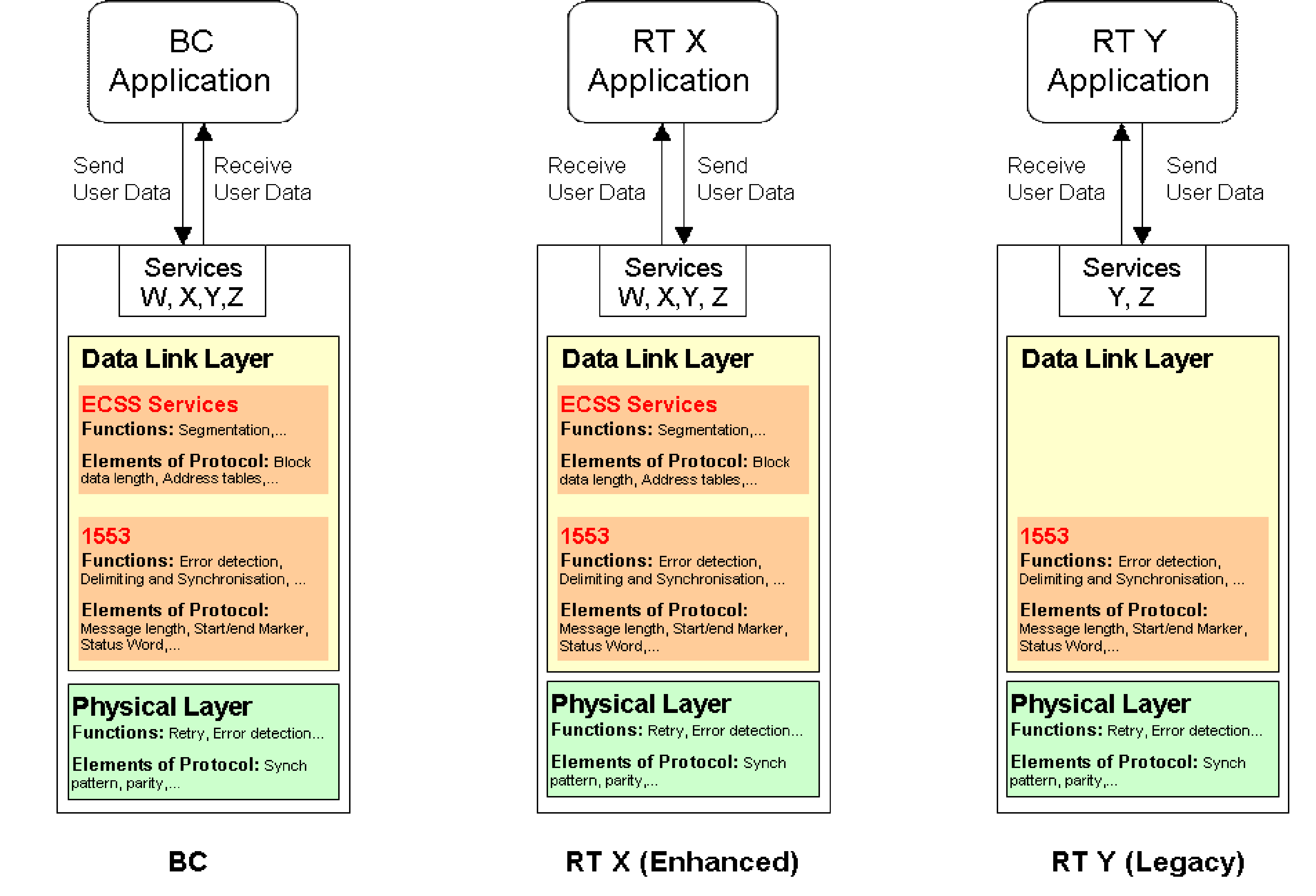 Figure 41: Architecture of typical communication devices with MIL-STD-1553B I/F
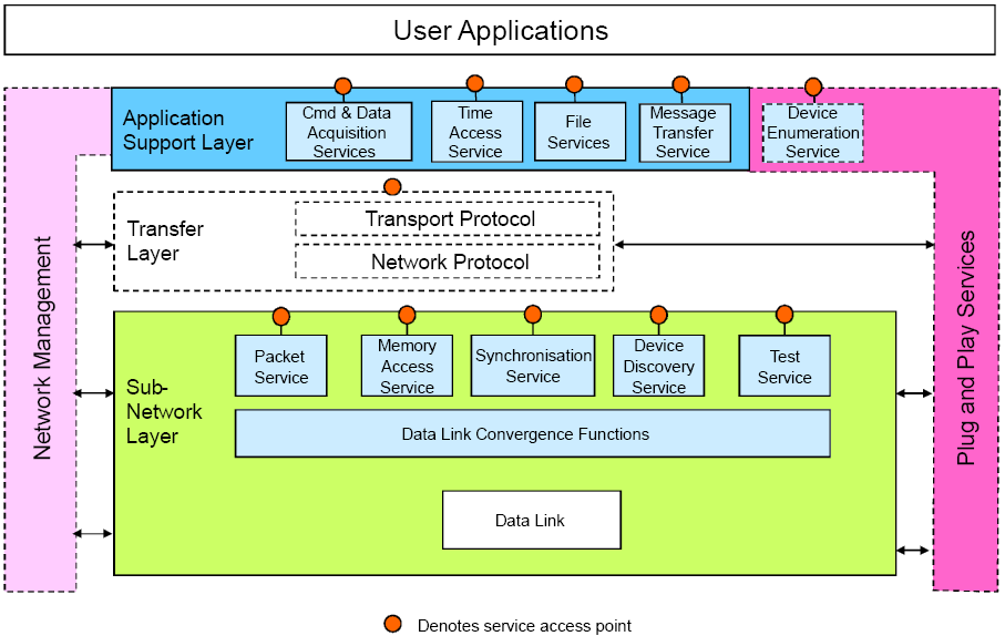 Figure 42: CCSDS/SOIS communication stack architecture
Service model
This clause describes a general model which is used for the definition of services in this standard. Figure 43 depicts this general service model.
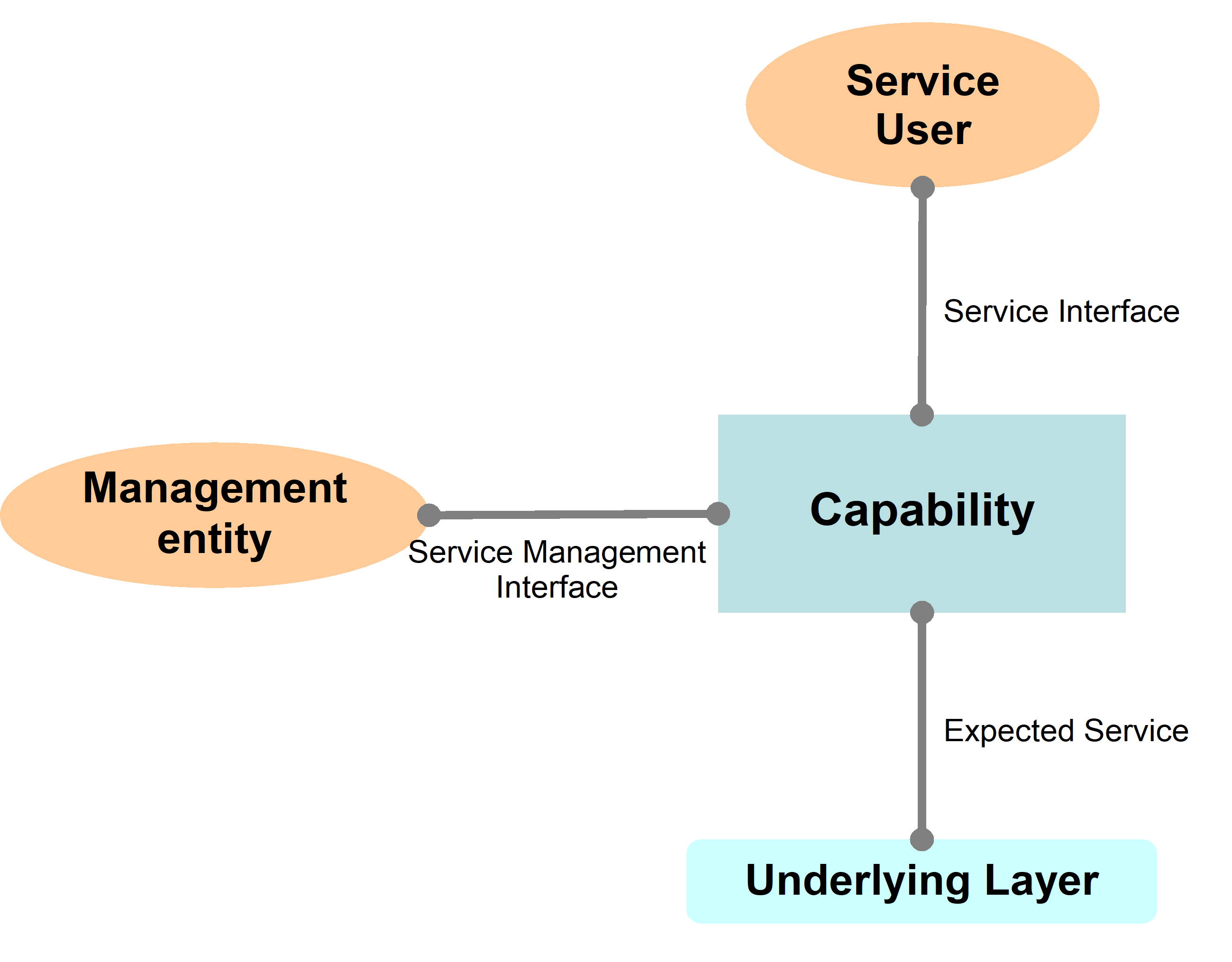 Figure 43: Service model
The services defined in this standard describe communication capabilities of service-provider which is provided to service-user at the boundary between service-provider and service-user.. This capability in its turn relies on certain services expected to be provided by the underlying layer. The interactions between the service-user and service provider constitute “abstract interface” at the service boundary. This abstract interface is defined in terms of service primitives which the service-user and the service-provider are allowed to exchange, together with sequencing rules which apply to these exchanges. The UML sequence diagram convention is used throughout this standard to illustrate how sequences of interactions are related in time. The OSI convention and terminology is used to represent service-primitives on those UML sequence diagrams. Services are configured and managed by a service management entity. Service primitives are described through their name (e.g. SendData, ReadStatus), type (e.g. Submit, Deliver or Requestor.Submit, Acceptor.Deliver) and list of parameters (e.g. GroupID, DataLength)
Service primitive is represented by an arrow.
Arrows located at the left of the vertical line indicate requestor primitives
Arrows located at the right of the vertical line indicate acceptor primitives
Arrows directed towards the vertical line indicate submit primitives
Arrows directed out of the vertical line indicate deliver primitives
Primitives are an abstract, atomic representation of an interaction between service-user and service-provider which are defined in clause 7 of this standard. The primitives and their parameters indicate what information flows between the service-user and the service-provider at their interface. This is not to be confused with an API which is associated with a specific implementation.
There are three types of parameters associated with each definition of a service primitive – Input, Output, and Managed. The CCSDS Draft Recommendation for the encapsulation service [CCSDS-133.1-R-1, Red Book, April 2002], provides the following definition for managed parameters: “In order to conserve bandwidth on the space link, some parameters associated with a Service are handled by management, rather than by inline communications protocol. The managed parameters are those which tend to be static for long periods of time, and whose change generally signifies a major reconfiguration of the service-provider associated with a particular mission. Through the use of a management system, management conveys the required information to the service-provider. The managed parameters are defined in an abstract sense, and are not intended to imply any particular implementation of a management system”. They allow configuring services according to specific application needs or options relevant to implementation. They are not defined within this standard but examples are provided in this informative clause.
1553 bus topology
This clause presents the bus topology used in the reference architecture (see Figure 44).
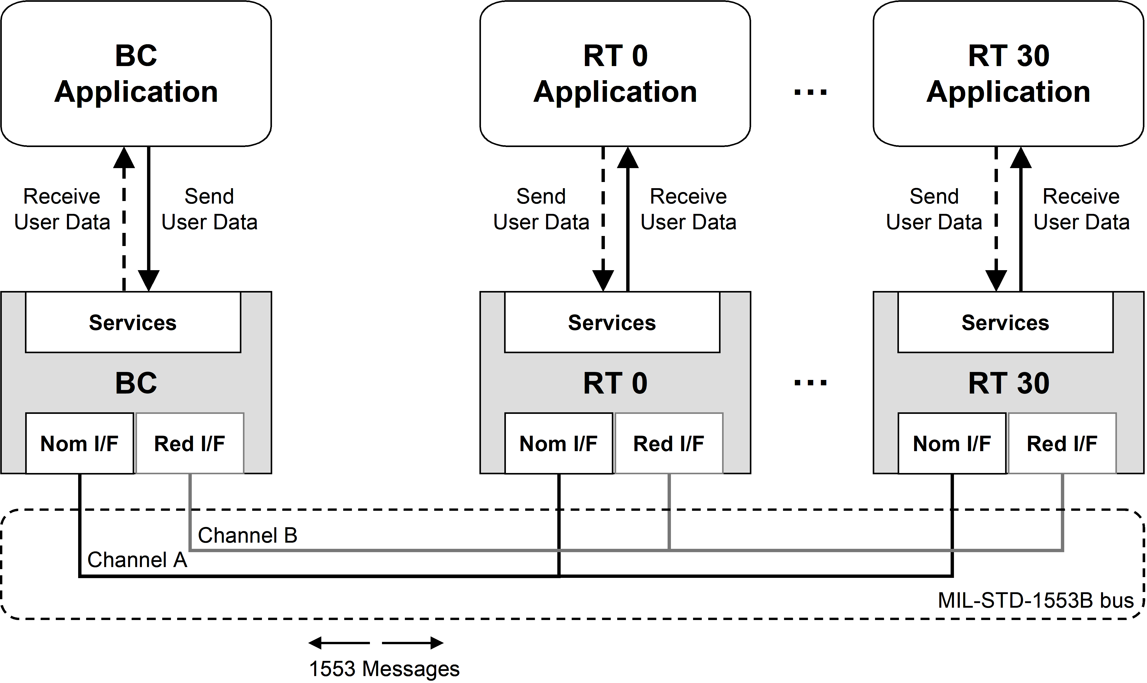 Figure 44: 1553 Bus topology
As defined in MIL-STD-1553B, the 1553 network connects the Bus Controller (master of the bus) with up to 31 Remote Terminals (bus slaves).
Bus management is strictly based on master-slave relationship between Bus Controller and the Remote Terminals.
The MIL-STD-1553B bus medium is composed of a nominal (Channel A) and a redundant (Channel B) physical interconnection.
Messages can be sent either on channel A or on channel B by the BC, and the RT replies always on the same channel. Here and in the other clauses, unless differently stated, the term 1553 bus includes nominal and redundant channels.
The management of the redundancy of channels and communication devices in a data bus system is out of the scope of this standard. However elements of this standard to be used by the user application to perform Failure Detection, Isolation, and Recovery (FDIR) tasks are identified within this Overview clause and highlighted in the clause 7.
In Figure 45, some examples of commonly used redundancy schemes are presented; alternate bus topologies to handle application specific fault tolerance or layout requirements are considered compliant to this standard as long as they are compliant to MIL-STD-1553B.
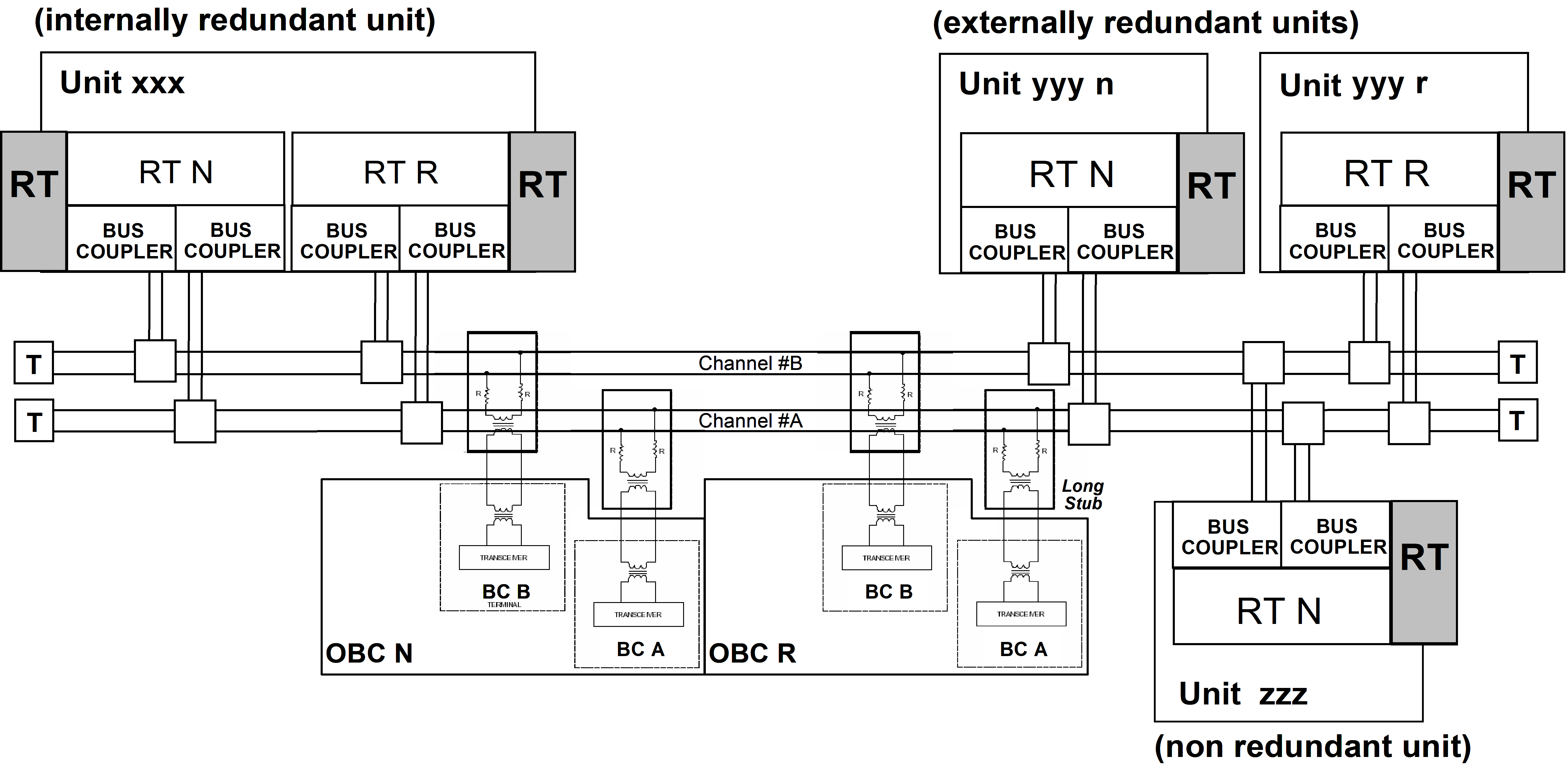 Figure 45: Examples of 1553 bus redundancy scheme
1553 bus scheduling aspects
Bus profiling and scheduling
A MIL-STD-1553B Bus is a resource shared between different users (BC and several RT) having different data routing, timing, etc. needs and constraints. Due to the limitations of the medium, it is mandatory to use the data bus in compliance with real-time systems requirements.
In particular, for spacecraft control, the data bus usage needs to be deterministic at any time. Because of that an important aspect in the management of the MIL-STD-1553B bus is the optimization of bandwidth allocation to the users in order to satisfy this overall system need. This operation, known as bus profiling, is often performed during the definition of the spacecraft-level system specifications and foresees the allocation of dedicated bandwidth for each activity on the data bus.
The user communication needs differ depending on the type of applications: some users require processing cycles including sequences of acquisition, processing and commanding, while others require only sporadic command distribution for instance. This has resulted in various definitions for bus profiling terminologies such as major frame, minor frames, sub-frames, slots and so on. The following proposed model preserves these user concepts with a common definition of the basic communication elements which are the Time Synchronization Cycle and the Communication Frame.
The bandwidth allocation is commonly organised as Time Synchronization Cycles split into Communication Frames. The frames are synchronous with the on-board time and/or the bus controller software cycles. As result of this, one or more alternative bus profiles (depending on different operational modes/phases) are created and can be applied on the actual system taking advantage of the autonomous or semi-autonomous features commonly supported by the Bus Controller devices.
Profiles can be specified only if users’ needs and constraints are represented by homogeneous and comparable attributes. It is possible to describe, build models and verify these needs in terms of requirements as early as possible in the spacecraft system design phase. These requirements put together describe a feasible system and present no inconsistency before the implementation at equipment level starts. As a result, the data bus system can be qualified through verification activities at individual communication devices, resulting in a working communication at the data bus system level.
 Figure 46: Process of Bus Profiling
In Figure 46, the bus profiling process is presented within the general process involving the spacecraft system specification definition and the system validation & verification. The term equipment is used to identify communication devices BC and RTs (including commercial-off-the-shelf and legacy products, where the specifications are taken “as is”).
Bandwidth pre-allocation
Service access type
Associated with each instance of data transfer are certain latencies, which are consequences of multiplexing data transmissions on a single data bus.
Depending on the desired latency and frequency requested it is foreseen to implement the service instances in two ways:
Access via pre-allocated bandwidth with populated content
Typically, services requiring low latency or “high” frequency (for example AOCS command and data acquisition, critical command distribution, cyclic housekeeping data acquisition) have the bandwidth pre-allocated using the populated content option: the time position of each 1553 messages in the timeline of the Communication Frame is always reserved to a given service with given attributes (e.g. RT address, maximum data size). In this case latency is defined a priori by the scheduling scheme itself (see example on Figure 47).
Access via pre-allocated bandwidth with unpopulated content
Sporadic/asynchronous or less critical service instances in terms of latency can “share” the pre-allocated but unpopulated remaining bandwidth (for example routing of sporadic telecommands from ground to an onboard application in an RT) unpopulated: access to the bus is performed in one of the pre-allocated time intervals where no specific 1553 message is scheduled for being transferred (unpopulated content). In this case only worst case execution latency is defined by the scheduling scheme; actual bus access latency is defined at run-time.
As shown in Figure 48, depending on the previous asynchronous requests, the “service Y request” can be executed in the first or the second unpopulated position (in grey) of Communication Frame #N. The user has knowledge a priory of the upper limit latency (worst case, request served in the second position), but the actual latency can only be measured at run-time depending on when the request is actually scheduled.
 Figure 47: Example of synchronous access (pre-allocated, populated)
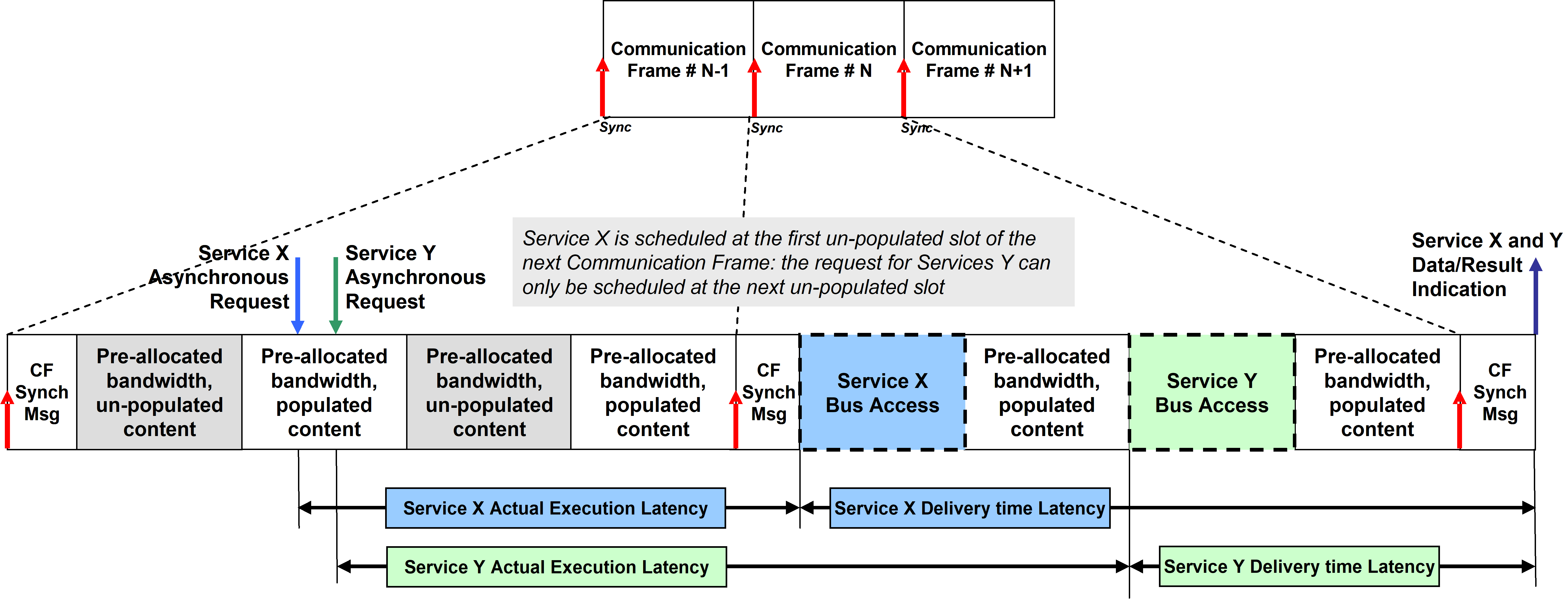
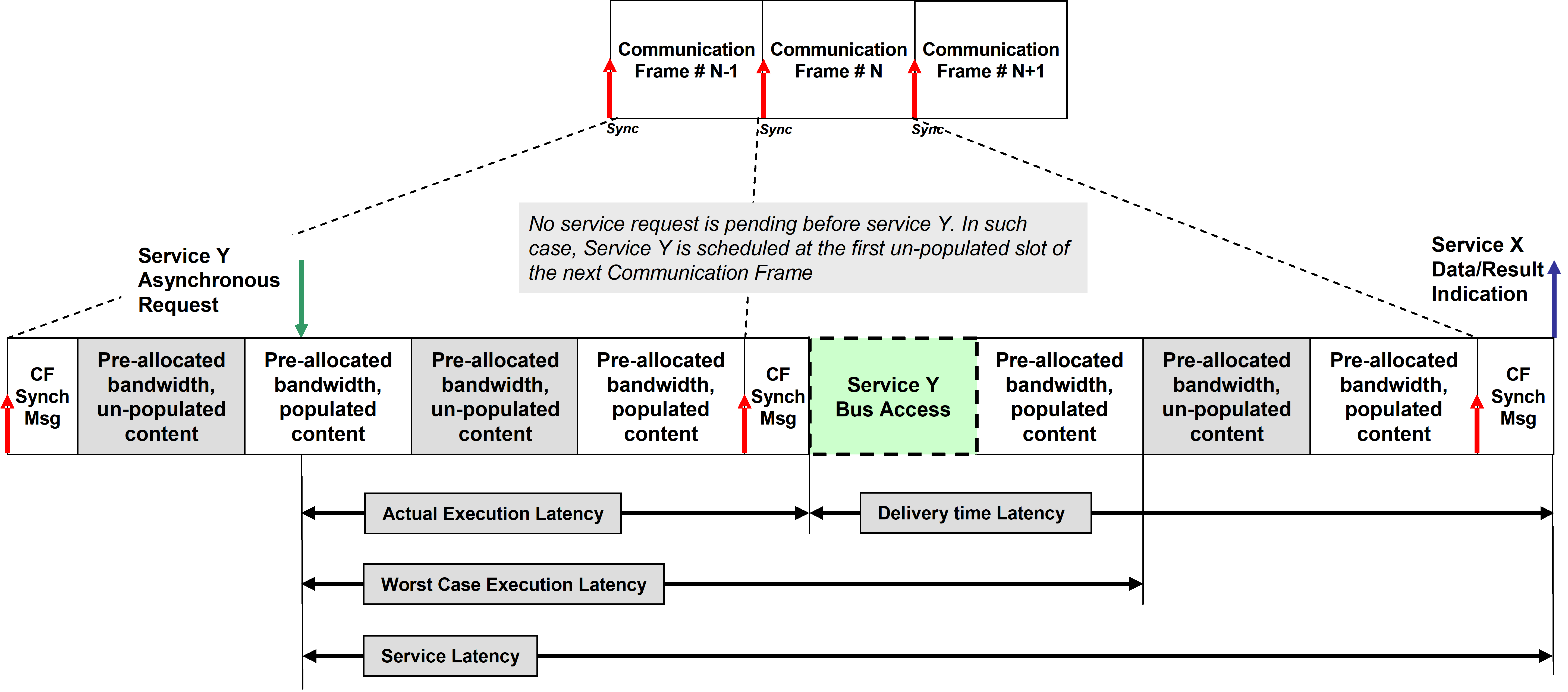 Figure 48: Examples of asynchronous access (pre-allocated, unpopulated)
Service latencies
In the cases described in 4.4.2.1 the requested latency is based on a priori knowledge by the user of the service(s) made available to it by the Data Link Layer. Thus a user not only has knowledge of the parties with which it can communicate, but also has explicit knowledge of the characteristics of the service it can expect to be provided with each invocation of the service.
Latency can be classified as follows:
Service Execution Latency: the time between the issuing of the service request and the start of the actual data transfer on the bus;
Delivery Time Latency: the time between the start of the data transfer on the bus and the time when the user is notified with the result of the service request (e.g. data available, error results);
Service Latency: the time between the issuing of the service request and the time when the user is notified with the result of the request.
According to the needs of the system designer, different Communication Frames can be adopted during different phases of the execution of the bus data transfers: the only strong requirement is to have the Communication Frame established at runtime, including all data to be transferred, before its execution is scheduled on the bus.
Implementation of the bus profile
Bus profiling benefits from autonomous functionality offered by modern Bus Controller communication devices. Typically, BC devices allows to be programmed setting up a list of messages to be scheduled in sequence or according to a given time delay (optional) known as “send-list” or “message-sequence” (see Figure 49).
 Figure 49: Typical implementation of 1553 messages sequence on BC
The host computer housing the BC device is in charge only to prepare the data to be delivered, to trigger the start of the sequence and to retrieve the returned data at the end of the sequence (typically notified by an interrupt) or handling error conditions. The BC device autonomously performs the low level operations of sending and receiving the elementary 1553 messages with respect to the programmed sequence (see Figure 410). In this context a bus profile can be efficiently implemented by programming the message sequence in the bus controller at initialization time and managed at run-time by setting up and retrieving data to be transferred on the bus.
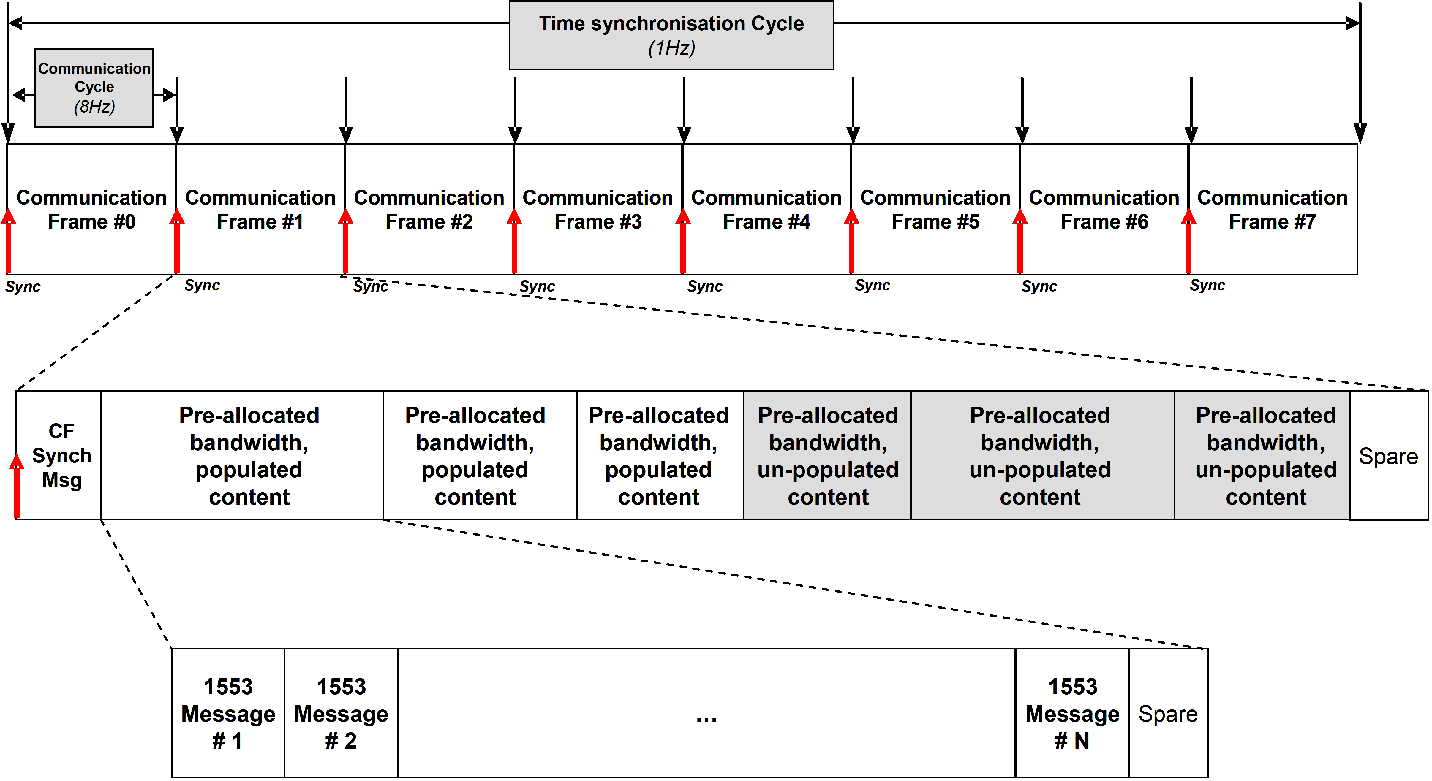 Figure 410: Typical communication frame decomposition on BC
If different operative modes or mission phases are foreseen, alternative profiles can be implemented by different and independent message sequences to be programmed and started on the BC according to the mission needs. As a basic principle, however, it is not recommended to modify a bus profile ad hoc in an adaptive, demand-driven way. As a result, data throughput and worst-case latencies can be guaranteed for each individual user, which is connected to the data bus - irrespective of the nominal or non-nominal behaviour of any other remote terminal.
Description of services
Overview
This clause provides an overview of the services defined in this standard within the data-link layer.
These services are:
Time service which supports the distribution of time information across a 1553 data bus.
Communication Synchronization service which supports time multiplexing of data bus messages in a deterministic way.
Set Data and Get Data services which support non-confirmed data transfers of restricted length with a simple protocol without handshake.
Data Block Transfer service which supports confirmed transfers of data blocks on request of the sender with handshaking supported by a protocol.
Terminal Management services which provide standard functions and structured data in support to the implementation of project specific terminal management.
This clause provides informal description of the services. The reader is referred to clause 7. of this standard (normative requirements chapter) for the detailed specification of the above defined services, as well as for the definition of message formats.
The services are not fully independent. The “Communication Synchronization” service is a mandatory general service which aims at guaranteeing real-time properties and which is used by all other services. The “Terminal Management” service relies on the “Get/Set service”, which in turn relies on the “Communication Synchronization” service. “Time”, “Get/Set” and, “Data Block Transfer” services are independent from each other but all rely on the “Communication Synchronization” service. The dependency graph is depicted in Figure 411.
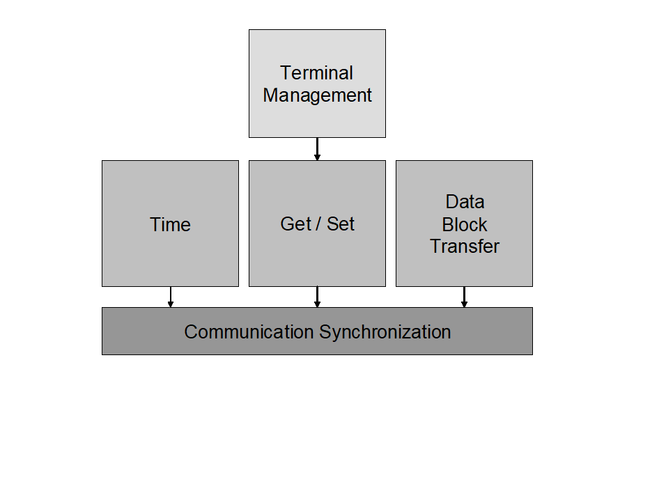 Figure 411: Services dependencies
The services primitives provide reporting on the service completion with respect to the service capabilities rather than a detailed view of the 1553 bus activity. No detailed view on the 1553 message transfer is provided which can be viewed as a restriction for failure investigation. However, experience has demonstrated that direct analysis of communication errors for FDIR purpose is typically what has failed in many projects because of the additional SW involved and its impact on performance generating problems in real-time operations. Therefore, this standard considers that specific details for offline FDIR analysis can be acquired through specific FDIR services which can be project specific or be specified in another standard.
Time service
The Time service supports distribution of reference time across a 1553 data bus from a central On-Board Time Master located at the BC side of the bus to one or more On-Board Time Slaves located on the RT’s sides. The distribution is done as a periodic process where two service primitives – TimeData and TimeSynchronize used in steps, as shown in Figure 412, are continuously repeated. The two service primitives can also be used separately in case one of them is not selected for use in a service-user (i.e. an application.)
Step 1:
A TimeData.Submit primitive is invoked by the On-Board Time Master to request service-provider at BC to distribute Time Message on a bus to all On-Board Time Slaves. This request contains the time that is valid now or at the next Time Synchronization Message in case if TimeSynchronize primitive is also used. The request results in a Time Message being sent on the data bus in broadcast mode or separately to all RTs, which deliver the received time to their local On-Board Time Slaves by invoking TimeData.Deliver primitive. Each On-Board Time Slave saves the received time for use in the next step. The time format is normalized by this standard.
Step 2:
When the next Time Synchronization Event occurs, the On-Board Time Master invokes Time Synchronize.Submit primitive. The request results in a Time Synchronization Message in the form of a Synchronize mode command being sent on the data bus in broadcast mode to all RTs or in the form of a separate signal on a dedicated line. The service-provider at RT invokes the TimeSynchronize.Deliver primitive to notify its service-user - local On-Board Time Slave - on occurrence of Time Synchronization Event. An On-Board Time Slave can then set its local copy of on-board time directly at the event or perform other algorithms to ensure that its local copy of onboard time is synchronous with the reference time.
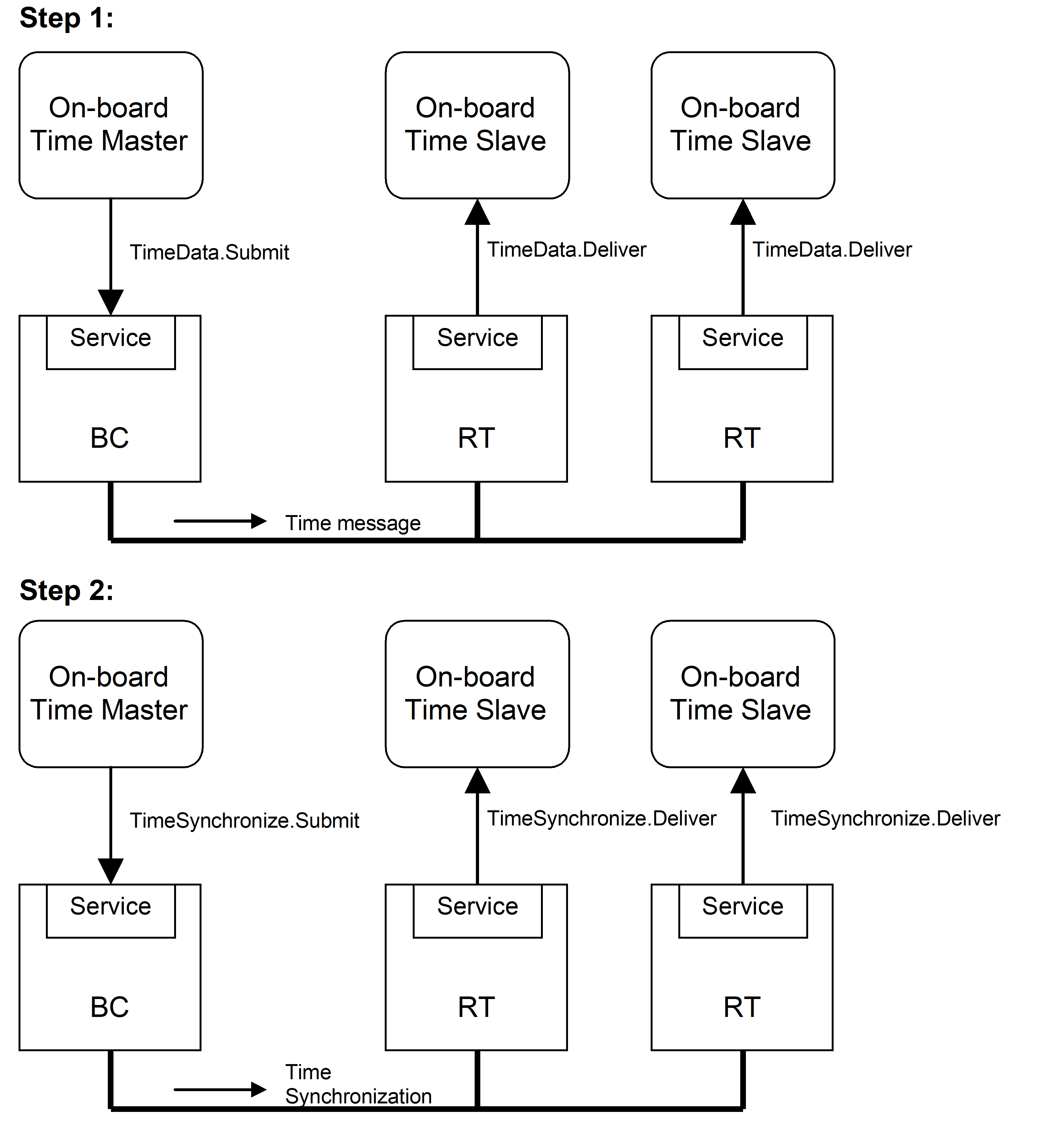 Figure 412: Time Service steps
In case of usage of the TimeSynchronize primitive, the process is started by the BC first sending a Time Message followed by the first Time Synchronization Message. As RTs can be powered at any point in time the RT applications are able to tolerate any order of appearance of two messages.
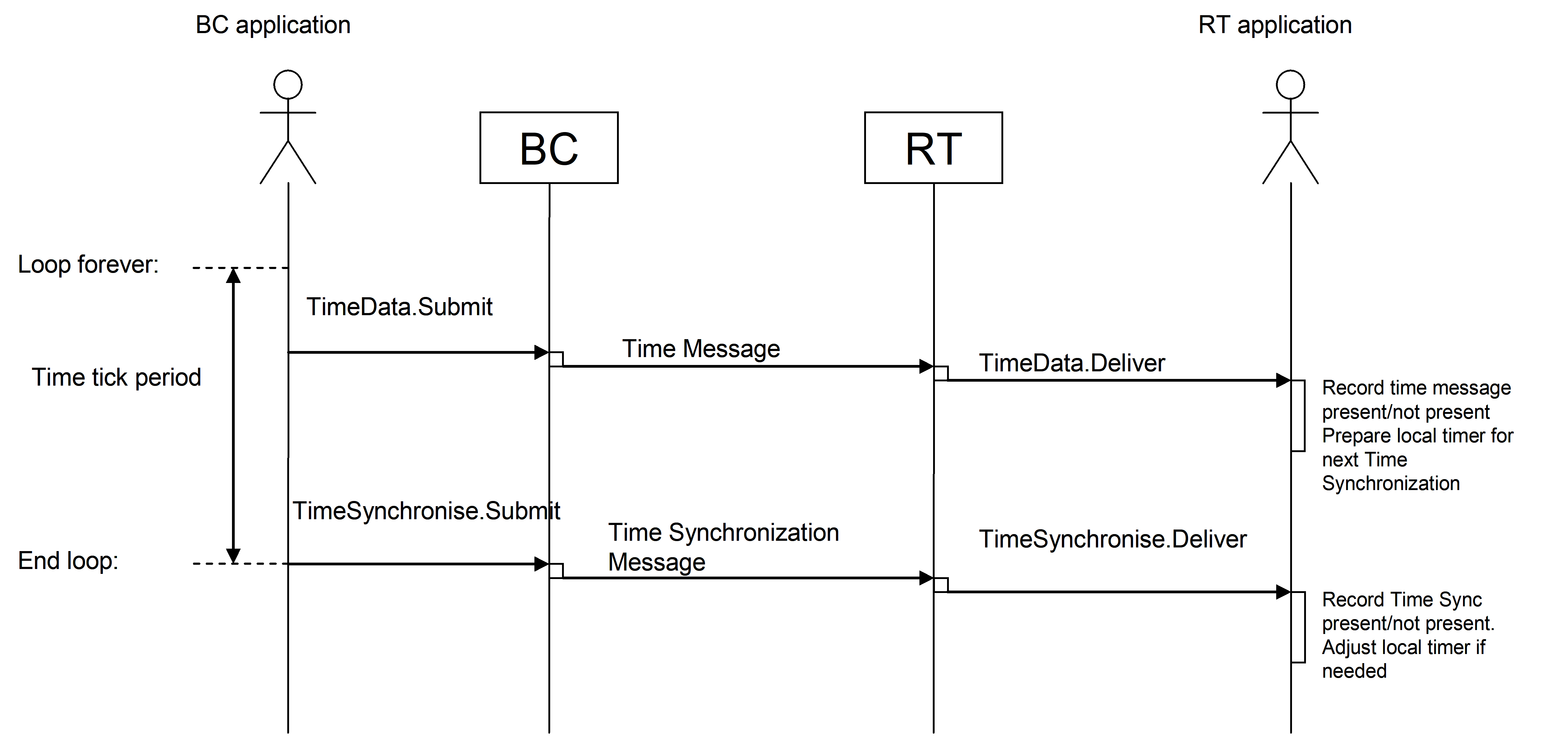 Figure 413: Time Service
The occurrence of a TimeSynchronize.Submit primitive is controlled by the On-Board Time Master. It is generated with a frequency that is naturally occurring in the time counter and that is extensively used in the system. For the 1553 data bus reference system described in this document a 1 second Time Tick Period is used.
As the On-Board Time Master can be both free-running and being synchronized to, for instance, a GNSS receiver there can be occasions where the OBT Master performs a synchronization operation. Two methods are allowed:
The OBT Master adjusts its frequency by speeding up or slowing down such that it within a reasonable time ends up in phase with the GNSS system. Typically the adjustment is made until the second ticks coincide and thereafter any coarse OBT setting can take place to keep the spacecraft exactly in phase with the GNSS system.
The OBT Master locks its frequency to the GNSS clock frequency but keeps running with a fixed offset relative to the GNSS system. This offset is then added to the Master OBT time when the time is sent on the 1553 bus. With this approach the subsecond part of the distributed time is typically not be zero when the Master OBT is in full sync.
The two primitives of this service can also be used separately. For applications requiring very accurate time synchronization, the Time Synchronization Message can be sent using a dedicated line (i.e. not being a 1553 Message). For applications requiring very coarse synchronization, usage of the TimeSynchronize primitive can be completely omitted. The accuracy also affects the resolution used in the Time Message, using the full resolution only makes sense if the Time Synchronization Message is distributed via a separate line.
For applications not requiring time distribution, such as simple cyclic control applications, the TimeData primitive can be omitted.
To allow RT application to correlate the two service primitives the BC has to provide some time for the RT to process a Time Message before the Time Synchronization Message is sent. The BC cannot send a new Time Message too soon after the Time Synchronization Message to allow the RT to process the Time Synchronization Message without having its time value changed. In Figure 414, these relations are shown as setup and hold times relative to the Time Synchronization Message.
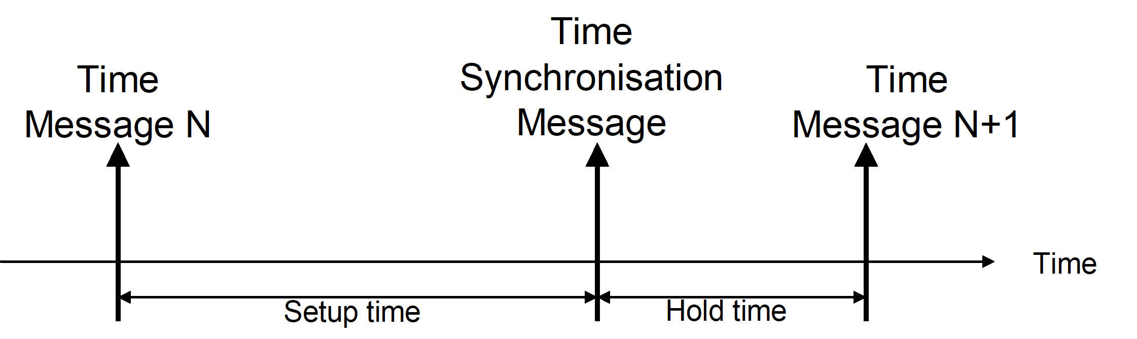 Figure 414: Time distribution and synchronization
An RT application that detects a missing Time Message or a missing Time Synchronization Message can report the condition using the RT Health monitoring function if it considers that the missing message can cause the RT to be unsynchronized.
Primitives:
|
* TimeData
|
This primitive is used by On-Board Time Master on the BC to distribute Time Message to all On-Board Time Slaves on the RT’s.
|
|
* TimeSynchronize
|
This primitive is used by On-Board Time Master on the BC to distribute Time Synchronization Message to all On-Board Time Slaves on the RT’s
|
Communication Synchronization service
The Communication Synchronization service supports time multiplexing of data bus messages and series of messages in a deterministic way, allowing determining in advance when a message is transferred on the bus.
The data bus communication takes place in time intervals called Communication Frames. Each Communication Frame on the data bus starts with a Communication Frame Synchronization Message in the form of a Synchronize with Data Word mode command. The data word indicates the number of the Communication Frame. Communication Synchronization Service is used to notify BC and RT applications on the start of Communication Frames. The BC application is informed about the start of Communication Frame by a CommunicationSynchronize service primitive.
When this service is used together with the Time Service which utilizes TimeSynchronize primitive, Communication Frame N° 0 starts with the Time Synchronization Message instead of the Communication Frame Synchronization Message. For this case it is also possible to vary the duration of the Communication Frames in order to keep in synch with the On-board Time Master, for instance due to differences in frequency between the 1553BC oscillator and the time reference oscillator.
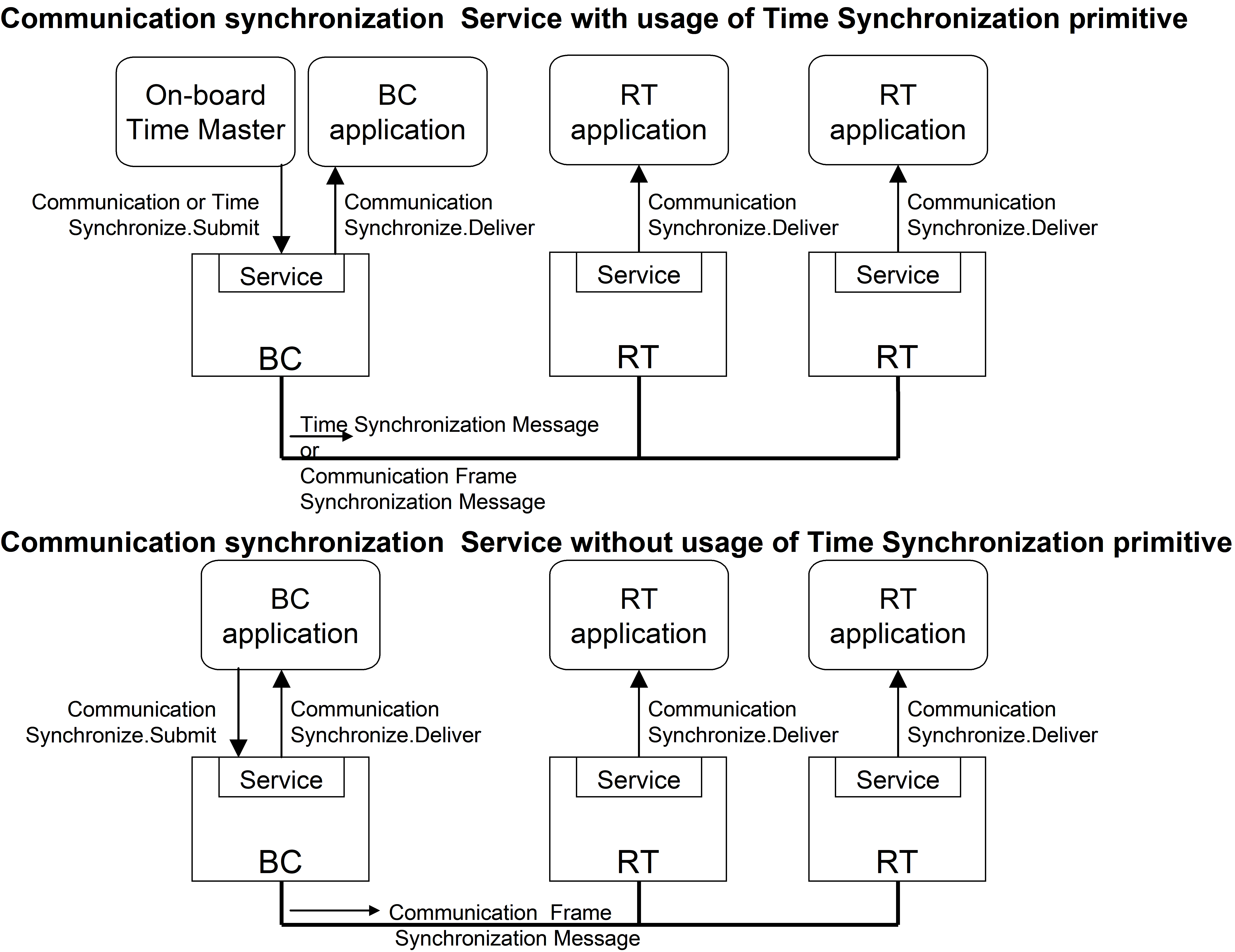 Figure 415: Communication Synchronization scenarios
The arrival of a Communication Frame Synchronization Message at the RT is signalled to the RT application through CommunicationSynchronize service primitive together with the current frame number.
To achieve an even better accuracy and determinism of the transfers it is also possible to schedule the transfer of an individual message relative to the start of the Communication Frame.
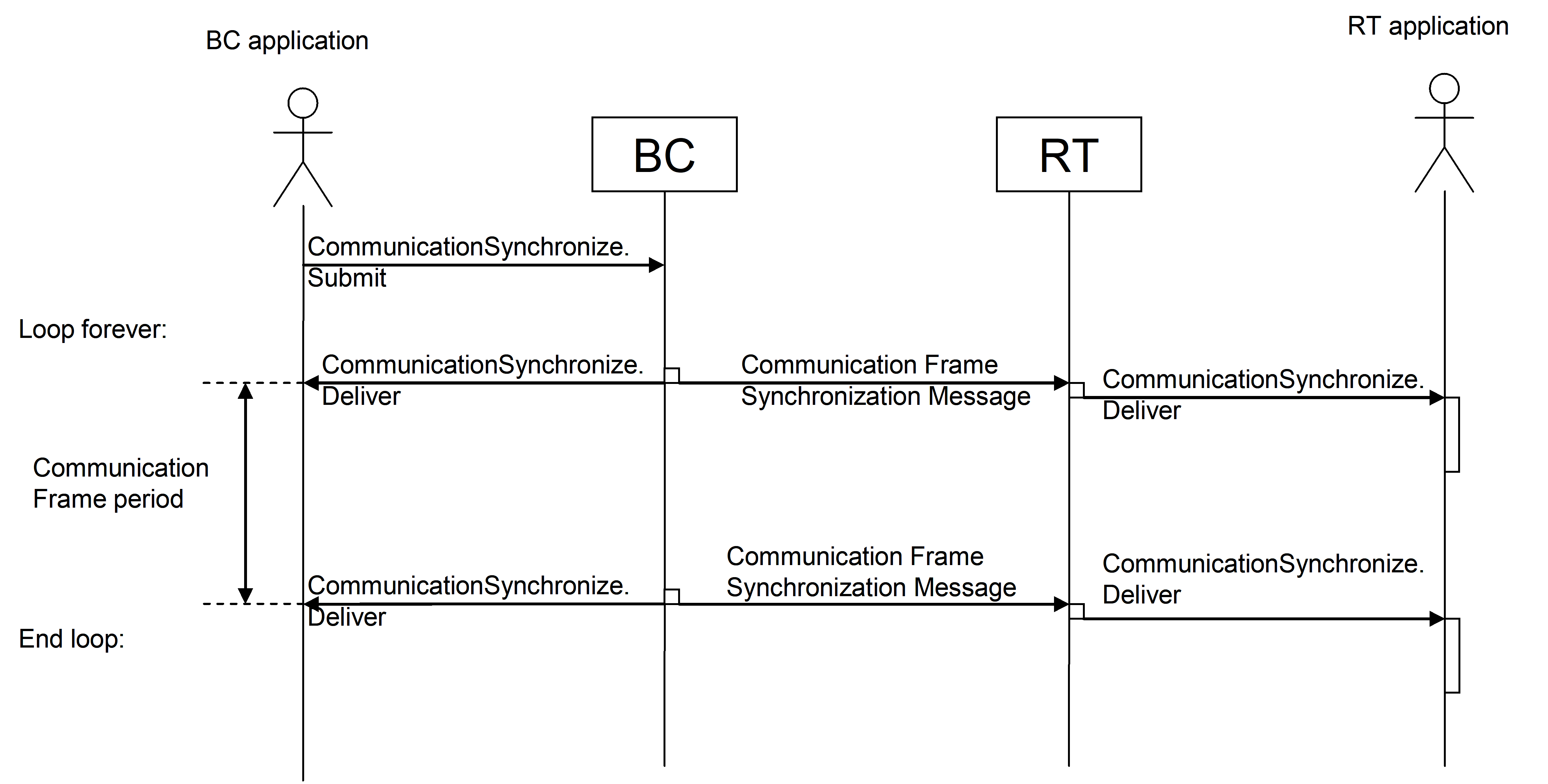 Figure 416: Communication Synchronization
Primitives:
|
* CommunicationSynchronize
|
This primitive is used by all on-board communication devices to synchronize their activities with respect to a common event: the Communication Frame Synchronization Message
|
Example of managed parameters:
The TimeSynchronize primitive of the Time Service can be supported or not
The number of Communication Frames per Time Synchronization Cycle or per second is configurable
In case TimeSynchronize primitive of Time Service is supported, the way to handle the synchronization of the two services is configurable either via “adjust the duration of all Communication Frames” or “adjust duration of the last Communication Frame before the next Time Synchronization Message”
The capability to control the start time of messages within all Communication Frames can be enabled or disabled.
Running with Time Service which utilizes TimeSynchronize primitive
The two methods of synchronizing the bus communication with the time are shown in Figure 417, where an example with the Bus Controller time running slower than the Master Time is given.
With the first method the duration of all Communication Frames is adjusted in order to fit an integer number of Communication Frames between two time ticks. With the second method the duration of the last Communication Frame is adjusted in order to make the same fit.
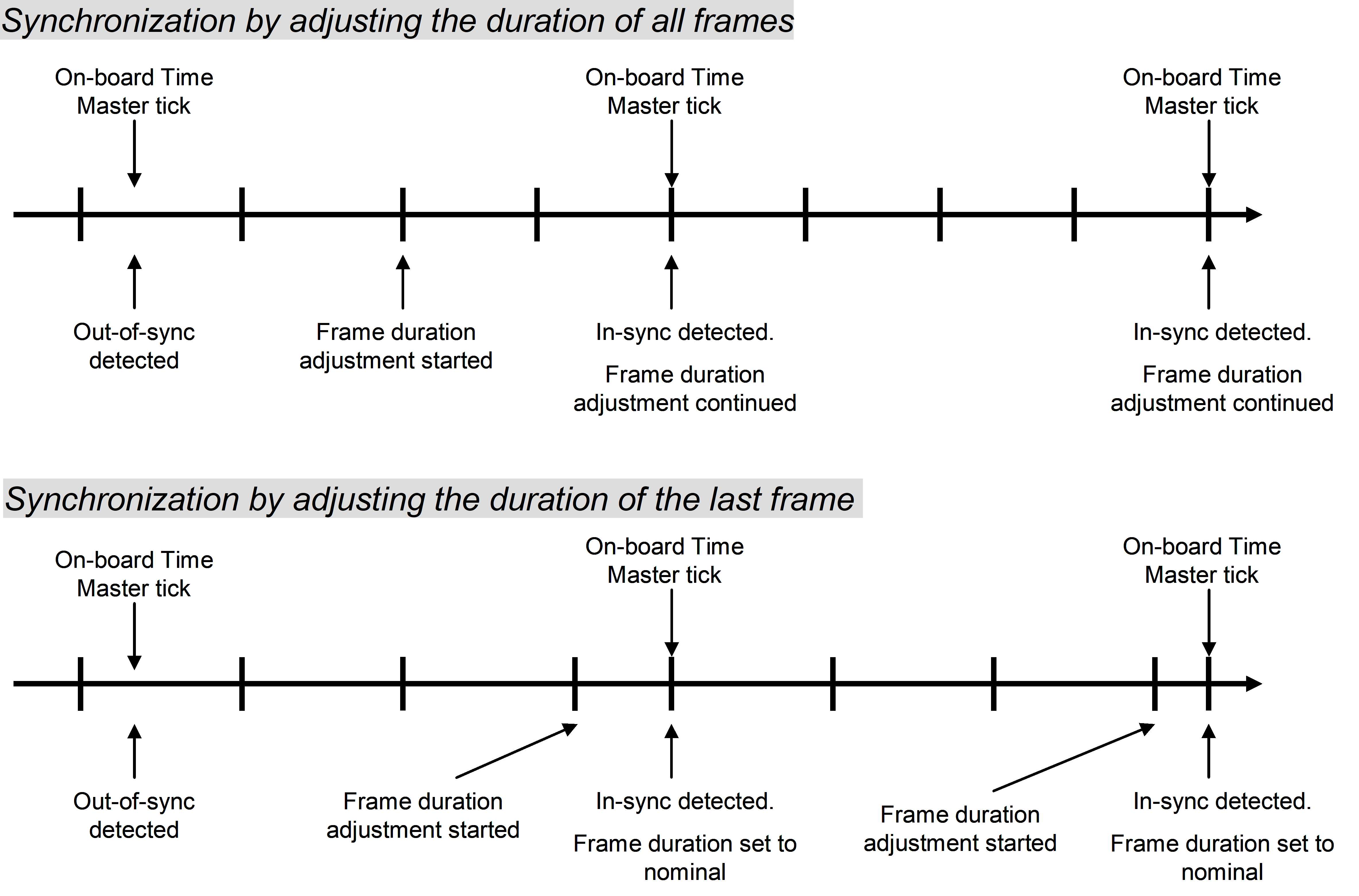 Figure 417: Communication Frame duration adjustment methods
Scheduling transfers within the Communication Frame
In order to ease the scheduling of data bus transfers the BC can optionally provide a mechanism to accurately determine when transfer takes place relative to the start of the Communication Frame. This mechanism assists in the bus profiling task, where it allows the designer to accurately locate all transfers such that there is no time conflict and such that the guaranteed latencies are met in all operational cases.
Distribution and acquisition: Set and Get Data services
Overview
The Get and Set Data services provide means to the service-user for transferring data of limited size length from source to destination in a single service access. Each of these services allows two service-users in a point-to-point configuration to communicate in one direction and deliver data to destination in a same structure in which it was presented at the source. The protocol does not carry data length of the data block and therefore require implicit knowledge of the messages length by the communicating pair (application on BC and application on RT).
The size of data is not limited to one 1553 message.
These services are asymmetric and are provided on the BC side only:
Set Data provides data transfer from BC to one RT
Get Data provides data transfer from one RT to BC
Although these services are provided on the BC side only, they do imply some indication on the RT side, which depends on the HW/SW implementation of the RT.
These services guarantee the delivery of data at data link layer by relying on the 1553 communication error detection mechanisms; they do not use additional confirmation mechanism within the data link layer.
These services aim at being generic and suitable to support short direct Command &Control type of messages. They also provide a simple segmentation mechanism for any upper layer protocol carrying larger data structures than 32-16 bits words without the need for hand-shake mechanism.
Set Data
Overview
Depending on the desired latency limit, Set Data service can be supported in two ways on the bus-profile level:
Type 1: Via pre-allocated bandwidth with populated content
Type 2: Via pre-allocated bandwidth with unpopulated content
In both cases this service guarantees delivery of data to the destination RT within bounded time. For both types of this service, it is the responsibility of the service-user application at the receiving end to ensure the timely retrieval of the delivered data before it can be overwritten by new data.
Set Data (Type 1)
This type of Set Data service utilizes pre-allocated bandwidth with populated contents to achieve provision of instances of the service which have tight latency constraints and/or require periodic distribution. It also utilizes Communication Frame generated by Communication Synchronization Service.
SendData.Submit primitive is invoked by service-user on the BC before the end of a Communication Frame-providing the corresponding identifier of the transfer carrying requested data within the Bus Profile and associated data to be sent. This request results in a transfer of provided data within the next Communication Frame to the communicating peer on the RT using predefined transfers supported by the underlying Bus Profile.
Once the transfer has been completed, the service-user on BC is notified by service-provider at the end of the Communication Frame of a data transfer completion via SendData.Deliver primitive with indication of the Communication Frame number.
The service-user can then retrieve a status of the transfer at data link layer level through the ReadStatus.Submit primitive.
For Type 1 of the service, validity of the data is ensured by the data transfer protocol (or underlying scheduling scheme). It is not indicated within the data itself. The application at RT can control the correct performance of the bus profile (underlying scheduling scheme) through monitoring of the Communication Frame number in the Communication Frame Synchronization Message or by other means at application level.
Primitives:
|
* SendData
|
This primitive is used by service-user (BC) to transfer data to communicating peer (RT).
|
|
* ReadStatus
|
This primitive is used by service-user (BC) to query status of a requested data transfer
|
Example of managed parameters:
List of valid SetDataIds
Data length for each SetDataId
 Figure 418: Set Data service
Set Data (Type 2)
This type of Set Data service utilizes pre-allocated bandwidth with unpopulated contents to transfer the data. It also utilizes Communication Frame generated by Communication Synchronization Service.
SendData.Submit primitive is invoked by service-user on BC before the end of a Communication frame, providing the corresponding destination (one RT with one or several subaddresses), the associated data to be sent, and the priority level of the data. The service-user is notified on identifier of corresponding transfer carrying requested data through the same primitive. This request results in a transfer of provided data within the next Communication Frame to the communicating peer on RT using one of the pre-allocated slots with unpopulated content, supported by the underlying Bus Profile, determined by the priority level of the data.
Once the transfer has been completed, the service-user in BC is notified by service-provider at the end of the Communication Frame of a data transfer completion SendData.Deliver primitive, with indication of the Communication Frame number.
The service-user can then retrieve a status of the transfer at data link layer level through the ReadStatus.Submit primitive.
To support the BC application, a concept of GroupId can be introduced. A GroupId can be considered as a virtual channel in the bus profile allowing the application to create for instance different levels of priority with a guaranteed bandwidth for each level. The GroupId is used as a parameter in the SendData.Submit primitive.
Primitives:
|
* SendData
|
This primitive is used by service-user (BC) to transfer data to communicating peer (RT).
|
|
* ReadStatus
|
This primitive is used by service-user (BC) to query status of a requested data transfer
|
Example of Managed parameters:
List of valid GroupIds
List of valid SetDataIds
Data length for each SetDataId, GroupId
Get Data service
Overview
Depending on the desired latency limit, Get Data service can be supported in two ways or bus-profile level:
Type 1: Via pre-allocated bandwidth with populated content
Type 2: Via pre-allocated bandwidth with unpopulated content
In both cases this service guarantees acquisition of data from the source RT within bounded time.
For Type 1 of this service, it is the responsibility of the destination user application (on BC) to ensure timely retrieval of the delivered data for further processing, before it can be overwritten with new data from the source (from RT).
For both types of this service, it is responsibility of the source user application (on RT) to ensure timely provision of the data before it can be read by BC.
For both types of this service, validity of the data is ensured by the data transfer protocol (or underlying scheduling scheme). It is not indicated within the data itself. The BC application can control the correct performance of the remote terminal or the updating of the to be acquired data through RT Monitoring Service, by sending a command using the Set Data service or by other means at application level.
Get Data (Type 1)
This type of Get Data service utilizes pre-allocated bandwidth with populated contents to achieve provision of instances of the service which have a tight latency constraints and/or periodicity requirement.
ReceiveData.Submit primitive is invoked by service-user on the BC. This primitive is implicit and is realized via CommunicationSynchronize.Submit primitive of Communication Synchronization service which starts the communication on the bus. This request results in starting the acquisition from the source RT using predefined transfers supported by the underlying Bus Profile. The destination service-user on the BC is notified of a new data arrival via a ReceiveData.Deliver primitive. Indication can be “explicit” by using a ReceiveData.Deliver primitive or “implicit” by using the Start of the next Communication Frame which releases all instances of Get Data services within a Communication Frame. The service-user then reads data from “data pool” of service-provider via the ReadData.Submit primitive.
Get Data service can imply some indication for the data source user (i.e. for the RT), which depends on the HW/SW implementation of the RT.
Primitives:
|
* ReceiveData
|
This primitive is used to initiate periodic data acquisition process from communicating peer (RT).
|
|
* ReadData
|
This primitive is used to retrieve acquired data from data pool of service provider.
|
Example of Managed parameters:
List of valid GetData Id
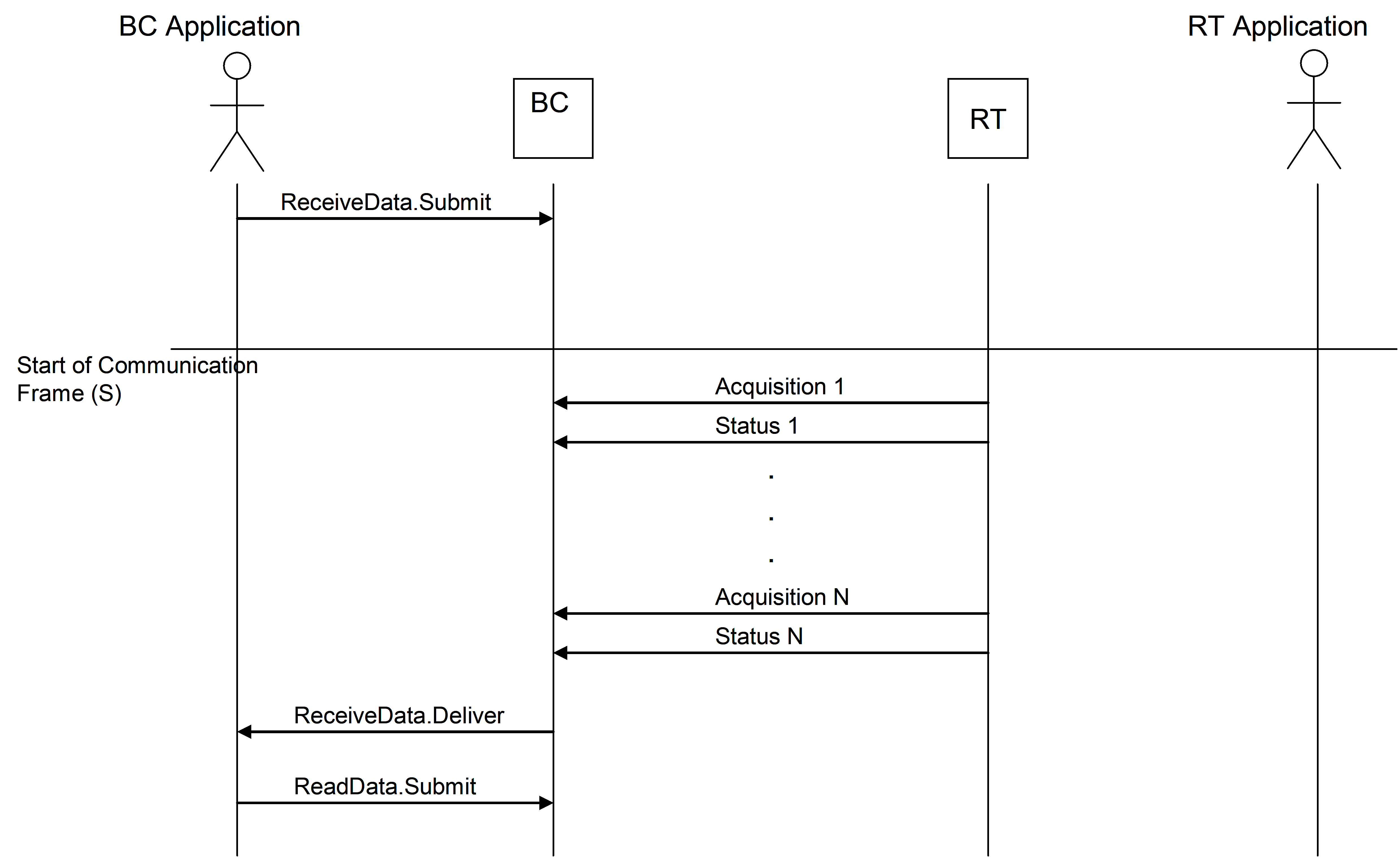 Figure 419: Get Data service
Get Data (Type 2)
This type of Get Data service utilizes pre-allocated bandwidth with unpopulated contents to achieve provision of those instances of the service which do not have tight “latency” constraints.
ReceiveData.Submit primitive is invoked by service-user on BC. This request results in starting the acquisition from the source on RT using preallocated bandwidth with unpopulated content supported by the underlying Bus Profile. The destination service-user on BC is notified on a new data arrival via an ReceiveData.Delliver primitive. Occurrence of this primitive, does not depend on the Communication Synchronization Event. Indication can be “explicit” by using a ReceiveData.Deliver primitive or “implicit” by using the start of the Communication Frame which releases all instances of Get Data services within a Communication Frame. The service-user then reads data via the ReadData.Submit primitive.
Get Data service can imply some indication for the data source user (i.e. for the RT), which depends on the HW/SW implementation of the RT.
To support the BC application, a concept of GroupId is introduced. A GroupId can be considered as a virtual channel in the bus profile allowing the application to create for instance different levels of priority with a guaranteed bandwidth for each level. The GroupId is used as a parameter in the Submit primitive.
Primitives:
|
* ReceiveData
|
This primitive is used to initiate data acquisition from communicating peer (RT).
|
|
* ReadData
|
This primitive is used to retrieve acquired data
|
Example of Managed parameters:
List of valid Group Ids
List of valid GetData Ids
Data length for each GetData Id, Group Id
Data Block Transfer service
Service overview
The Data Block Transfer Service provides the capability to transfer Data Blocks on request of the sender with a confirmation upon its completion. It supports the delimited and synchronized transfer of Data Blocks of variable size from 1 byte to a maximum size which is mission specific and can be selected to be either 1024 bytes or 4096 bytes. These Data Blocks are segmented as needed for 1553-messages at the sending side; they are de-segmented at the receiving side. Transfers of Data Blocks are multiplexed or de-multiplexed by the BC for up to 31 RTs, using address resolution.
The service is intended for “intelligent” RTs which have the capability to segment and assemble large data structures and to handle hand-shaking. To transfer data blocks to and from “non-intelligent” RTs the Get and Set services are recommended.
The Data Blocks handled by the Data Block Transfer Service can be Telemetry or Telecommand-Packets in conformance with the Packet Utilization Standard, ECSS-E-ST-70-41. However, as the internal structure of a Data Block is transparent to the Data Block Transfer Service, any type of data can be transferred by this service.
The Data Block Transfer Service uses handshake across the communication link between sender and receiver for flow-control, for positive confirmation of reception by the receiver, and for preventing duplications of transfers. There is no control flow requirements at the level of the protocol extension but the information carried in the control area of the transferred data blocks can be handled at the application layer for implementation of a control flow mechanism. This service delivers Data Blocks at the receiving side in the same sequence as the sequence at the sender. Two Quality-of-Service levels are supported by this service:
Best Effort, which transfers the data without any check for correctness of the data itself.
Verified Length, which transfers the data with the receiver checking that the correct number of bytes has been received with no data bus transmission errors.
Error detection is supported by utilizing the error detection capabilities provided by the MIL-1553B Std. In case of transmission errors, these detected errors are reported to higher protocol layers within the BC or the RTs in support of FDIR.
The Data Block Transfer Service also provides a protocol reset capability. The reset is performed separate for each BC-RT communication link and also separate for each direction, BC RT and . The reset can be used at the first start-up of a communication device or in case communication problems occur. The reset is normally initiated by the sender of a Data Block, i.e. the BC initiates a reset of the BC RT communication and the RT initiates a reset of the RT BC communication. However, since the BC is the master in a 1553 data bus system the BC also has a capability to command the RT to initiate a reset of the RT BC communication. This functionality reduces the needs for complicated time-out mechanisms inside the RTs and is typically used in case the BC is reconfigured and wants to restart all ongoing communication sessions with the RTs.
When a guaranteed delivery of certain data is required for a certain mission, it is handled by the service user, using the support provided from the Verified Length Quality-of-Service level.
The Data Block Transfer Service does not provide support for encapsulation/de-encapsulation of user data structures larger than the maximum block length. If larger data blocks are needed, the associated service characteristics is guaranteed at higher protocol layers, making use of control structures of these higher layer services (example: If a certain mission handles TM/TC Packets, which exceed the maximum block length of this service, or if file transfer is needed, Service 13 of ECSS-E-ST-70-41 should be used at layers above this Data Block Transfer Service protocol layer.)
For transfer of data, two ways of using the 1553 subaddresses are supported:
“Flat” sub-addressing, where different subaddresses are used to transfer different sections of the transmitted data block. In this mode the maximum block length that can be transmitted is 1024 bytes and this standard defines the subaddresses to be used.
“Deep” sub-addressing, where a single subaddress is used to transfer different sections of the transmitted data block. In this mode the maximum block length that can be transmitted is 4096 bytes and the subaddress usage is determined by the RT design.
The selection of the sub-addressing mode to be used for a certain RT depends on the design of that RT, and, in general, the BC is able to adapt to both types and to use both types in parallel for different RTs. However, for specific spacecraft missions, certain subsets of capabilities can be chosen.
The service primitives are formally symmetrical for a BC and a RT. However, as all actual timing and data exchange are initiated and controlled by the BC, in conformance with a strict master-slave-architecture of a MIL-Std 1553B data bus system, the actual details with respect to timing latency are different for a BC or a RT. Also, activities within a BC or RT which support the protocol are asymmetric. These differences are highlighted in the following clauses, when they are relevant.
To distinguish service usage by service-user located on BC side versus service-user located on RT side the following naming convention is adopted:
a BC-> RT transfer is called a Data Distribution transfer;Data Block associated with this transfer is called Distribution Data Block.
a RT-> BC transfer is called a Data Acquisition transfer;Data Block associated with this transfer is called Acquisition Data Block.
Primitives:
|
* SendData
|
This primitive is used to initiate transfer of data from data source to the data destination.
|
Example of Managed parameters:
Address configuration table (BC side only)
Subaddressing mode
Maximum data block size
Data Block Transfer control messages:
For the Data Block Transfer service certain control messages need to be exchanged across the data bus between BC and RT before and after the transfer of user-data. Each single data transfer in conformance with the Data Block Transfer Service is initiated by the exchange of either:
an Acquisition Transfer Request for RT-to-BC-transfers, or
a Distribution Transfer Descriptor for BC-to-RT-transfers
A corresponding
Acquisition Transfer Confirmation for RT-to-BC transfers or
a Distribution Transfer Confirmation for transfers
is exchanged after the completion of the data transfer. These messages provide the necessary information about the transfer such as data size, flow control and error status.
The Distribution Transfer Descriptors and Acquisition Transfer Requests consist out of two words each. Details are defined in clause 8.6.1 for Distribution Transfer and clause 8.6.2 for Acquisition Transfer.
Protocol start-up and reset
Before starting communication between the BC and RT, a protocol reset is made. A reset of the protocol is not necessary after a switch from bus medium A to medium B, or vice-versa. The Data Distribution protocol reset is initiated by the BC. The Data Acquisition protocol reset is normally initiated by the RT but it can also be initiated by the BC, using the Terminal Management service to force the RT to initiate a protocol reset procedure.
A protocol reset can also be made while the protocol is running in case communication errors are detected. If the BC application detects a communication error it can first initiate a protocol reset and attempt to resume communication before other ways of re-establishing communication is made. Also here the BC can initiate the Data Acquisition protocol reset using the Terminal Management service to force the RT to initiate a protocol reset procedure.
Data distribution
A BC RT transfer is called a Data Distribution transfer. The SendData.Submit primitive is invoked by service-user on BC to request service-provider to transfer Data Block to the destination peer on RT. This request contains the Destination Address, User-Data, User-Data length, and requested level of Quality of Service. The request results in the distribution of a Data Block and a Distribution Transfer Descriptor by service-provider on BC to a requested RT by writing a Distribution Data Block and Distribution Transfer Descriptor into the Subaddress-buffers, which are foreseen for these data.
For an RT, a new Distribution Data Block can arrive at any time. The RT has to check continuously if a new Distribution Transfer Descriptor indicating new data has arrived. If this is the case, the RT has to process the new command Data Block before the end of the Communication Frame following the one in which the Distribution Transfer Descriptor was received, such that the buffers used for a Distribution Data Block are free to receive a next Data Block in a following frame.
During the processing of the last Distribution Transfer Descriptor and Distribution Data Block, the service-provider on RT places a Distribution Transfer Confirmation into the Subaddress-buffer foreseen for it. It also notifies service-user on RT of a new data arrival by invoking SendData.Deliver primitive. The Distribution Transfer Confirmation acts as an acknowledge that the Distribution Data Block is received and, depending on the Quality-of-Service requested by the BC, it can also carry error information detected by the service-provider on RT. Also depending on the Quality-of-Service, the Distribution Transfer Confirmation can be polled by the service-provider BC during one of the next Communication Frames Thereafter, the service-user on BC can request distribution of a next Data Block to that RT.
If the BC concludes from the Distribution Transfer Confirmation and the 1553 Status Response words from that RT, that the Data Distribution was not successful, it reports a transfer error through the SendData.Deliver primitive to the service-user on BC.
Figure 420 describes the nominal sequence of activities of the BC and a RT for a single data distribution.
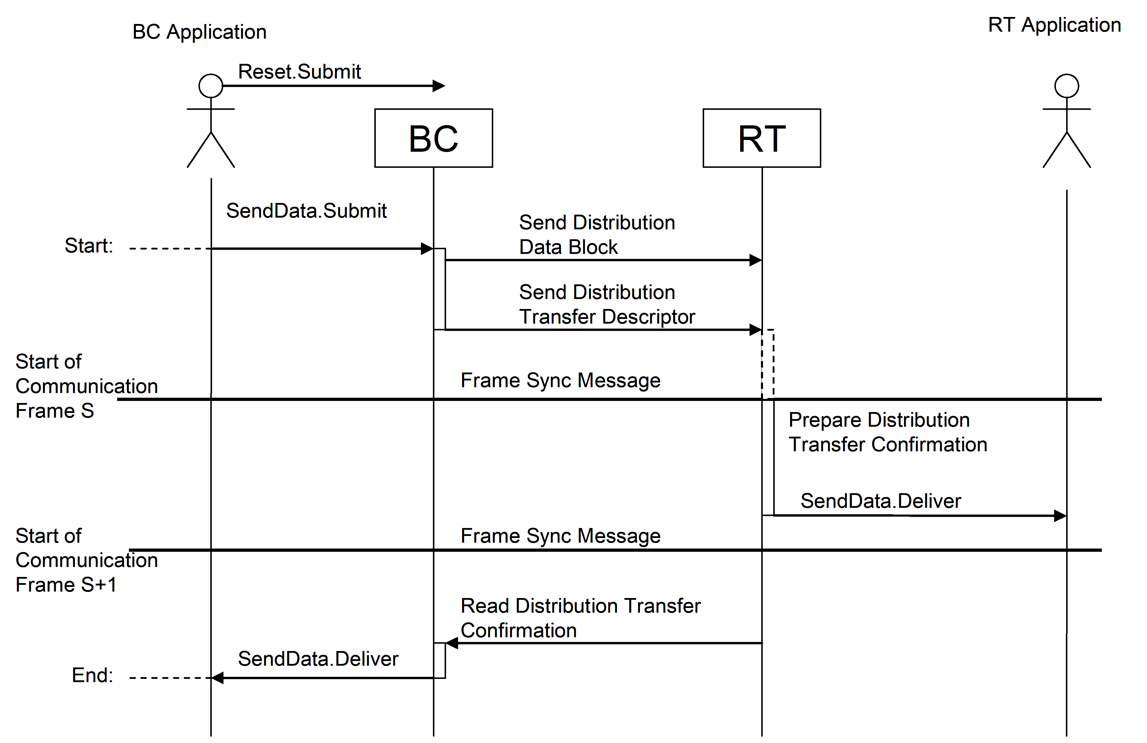 Figure 420: Data Distribution Transfer, BC to RT.
In Figure 421, the timing for the Best Effort QoS is shown. The gaps in the timeline show where there can be additional delay of one or more complete Communication Frames depending on the selected bus profile and the RT application timing. For maximum performance when communicating with an RT the gap can be zero, resulting in the protocol being able to transfer one user data block to that RT every second Communication Frame.
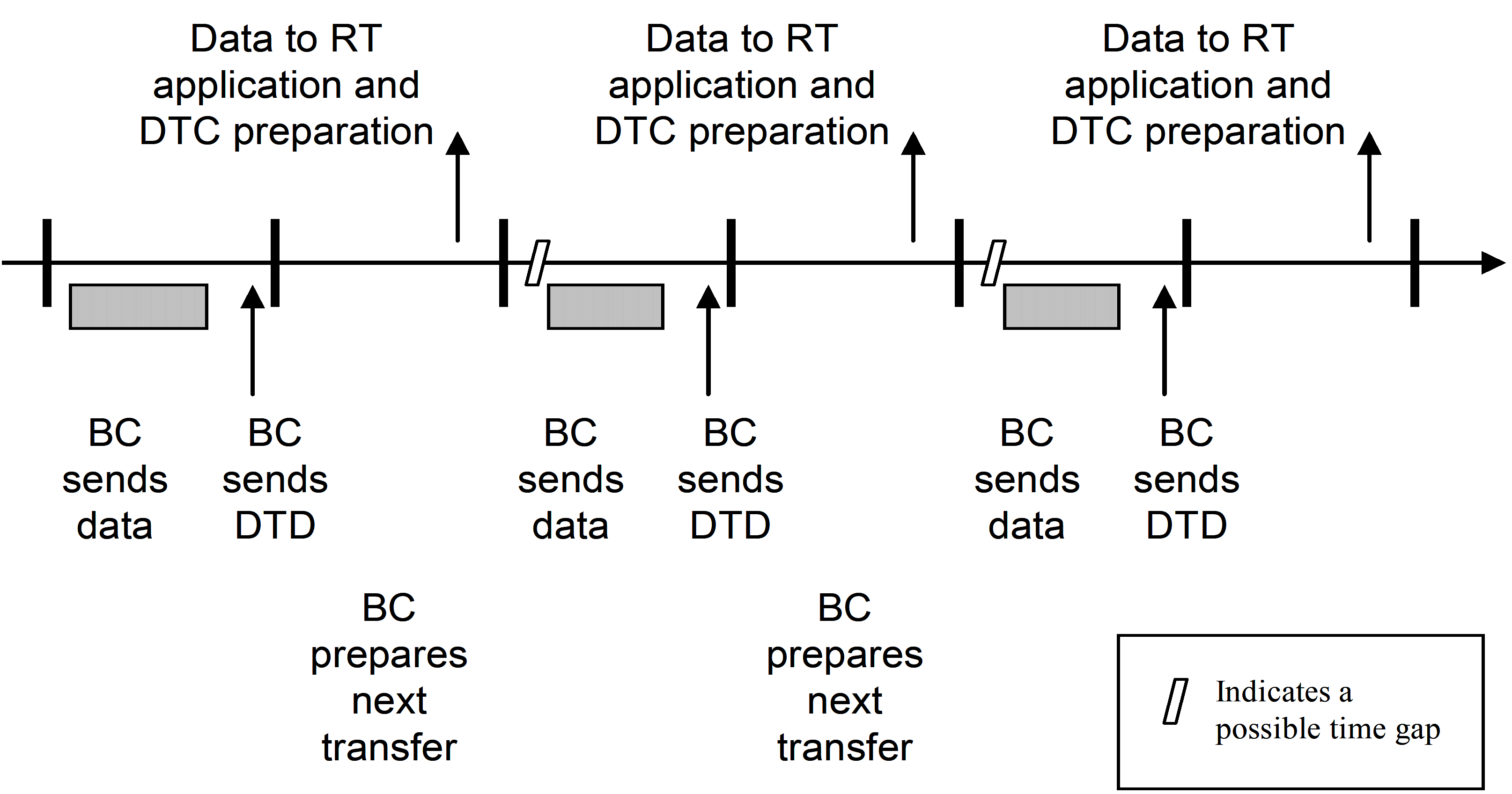 Figure 421: Data Distribution timing with Best Effort QoS
In Figure 422, the timing for the Verified Length QoS is shown. With a zero gap the maximum performance to a single RT in this case is one user data block every fourth Communication Frame.
As far as the Data Block Transfer protocol is concerned, an RT is not allowed to indicate, that it is not ready to receive a new Distribution Data Block. It also processes a Distribution Data Block at any time as needed. If this cannot be guaranteed by the RT, because of reasons related to the 1553-interface, or because of other reasons, the RT should allow, that any last Distribution Data Descriptor and Distribution Data Block can be overwritten by the BC. The protocol does not support features, which allow the BC to "wait" for a certain RT.
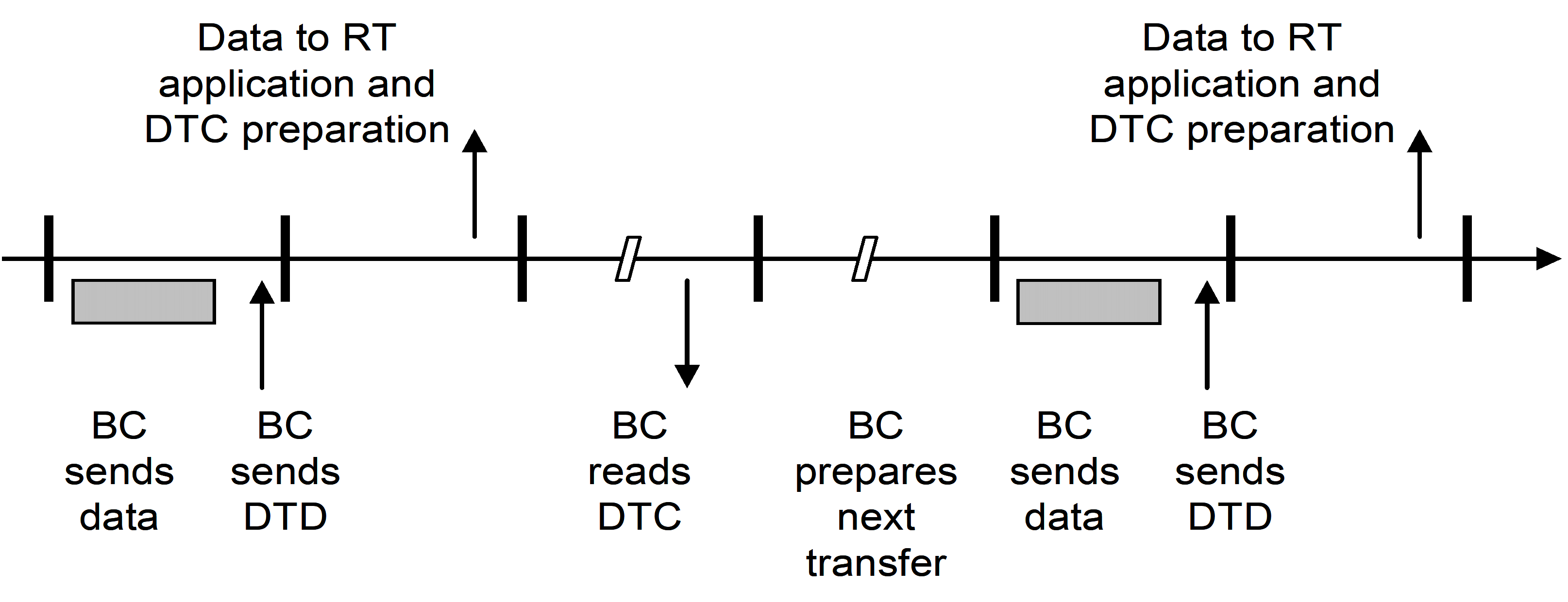 Figure 422: Data Distribution timing with Verified Length QoS
There can be cases where an RT can only tolerate a certain maximum rate of commands per second. There can also be cases where an RT has certain operational periods (e.g. initialisation, reset), during which it does not react to commands, or has other specific needs. These features are not directly supported by the Data Block Transfer protocol and should be handled by RT management functions at application layer, potentially supported by a proper bus profiling design.
Data acquisition
An RT BC transfer is called a Data Acquisition transfer. As the RT can not send a direct request to the BC, the BC regularly polls each RT which is currently active to find out whether that RT has any data to send. This is done by polling the RT for its Acquisition Transfer Request.
SendData.Submit primitive is invoked by a service-user on RT to indicate new data ready for acquisition and initiate data transfer to BC. The service-provider on the BC, reads this indication of new data, and initiates transfer of these data from the already pre-loaded Transmit-Subaddress-buffers of that RT during the next Communication Frame, which is scheduled for acquisition from this RT. Only one Data Acquisition from each RT at a given time is supported by the service. If there is more than one Acquisition Data Block to be sent, the RT application should queue these Acquisition Data Blocks in some internal buffer.
Depending on the Quality-of-Service requested by the service-user on the RT, the service-provider on the BC checks if the acquisition was complete and error-free. The service-provider on the BC always returns an Acquisition Transfer Confirmation indicating that the data has been transferred. If the service-user on the RT has requested a check of the transfer, the Acquisition Transfer Confirmation also indicates whether the transfer was successful or not. The RT service-user application may then decide to make a new transfer request with the same data or with new data, depending on application specific needs.
Only after reception of a new Acquisition Transfer Confirmation, the RT is allowed to raise a new Acquisition Transfer Request.
Figure 423 describes the nominal sequence of activities of the BC and an RT for a single data acquisition. Note that some Communication Frame Synchronization Message can be omitted for the Best Effort Quality-of-Service. The actual timing for a specific mission depends on restrictions given by this standard and on the selected bus profile.
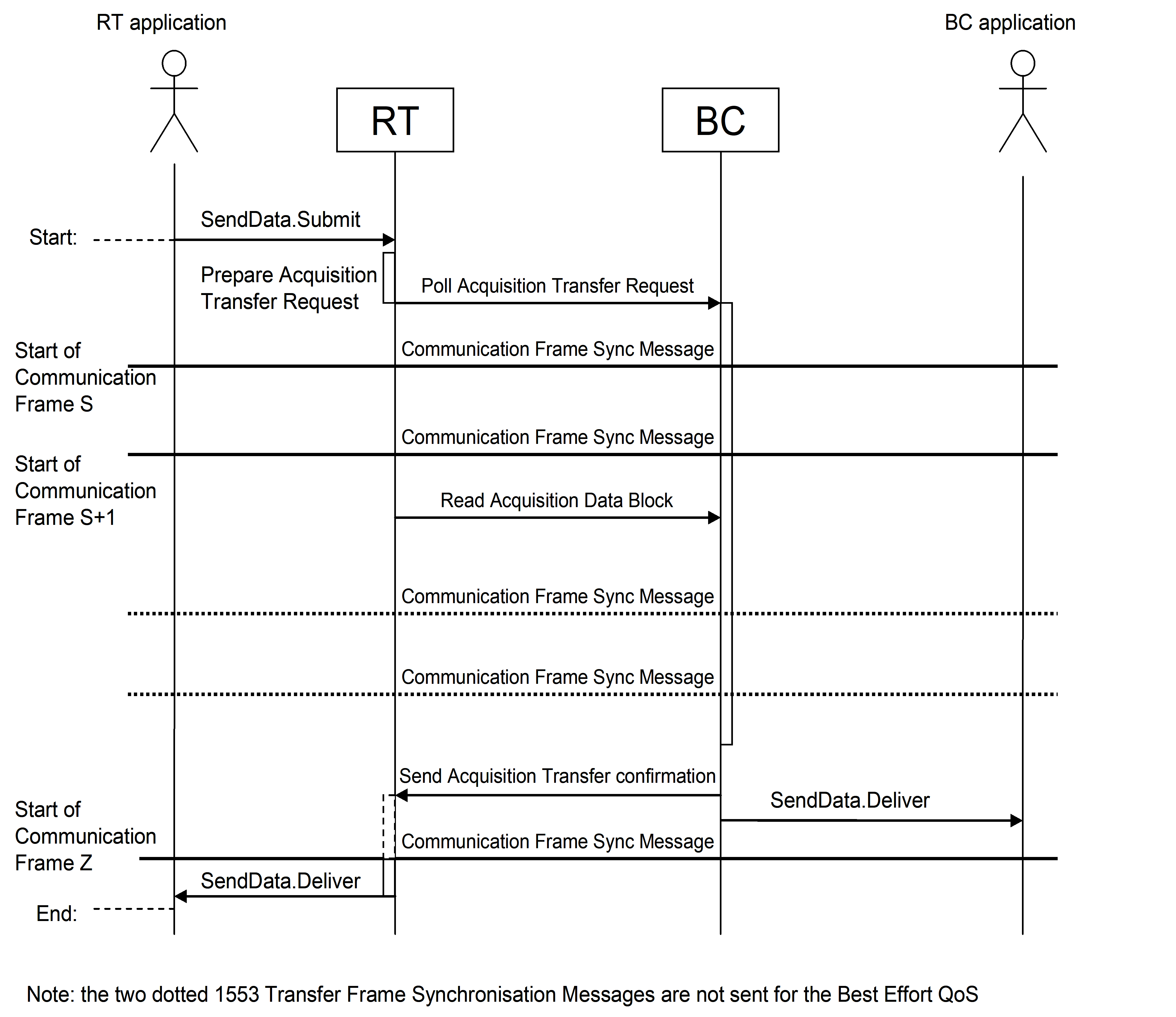 Figure 423: Data Acquisition Transfer, RT to BC
In Figure 424, the timing for the Best Effort QoS is shown. The gaps in the timeline shows where there can be additional delay of one or more complete Communication Frames depending on the selected bus profile and the RT application timing. For maximum performance when communicating with an RT the gap can be zero, resulting in the protocol being able to transfer one user data block from that RT every third Communication Frame.
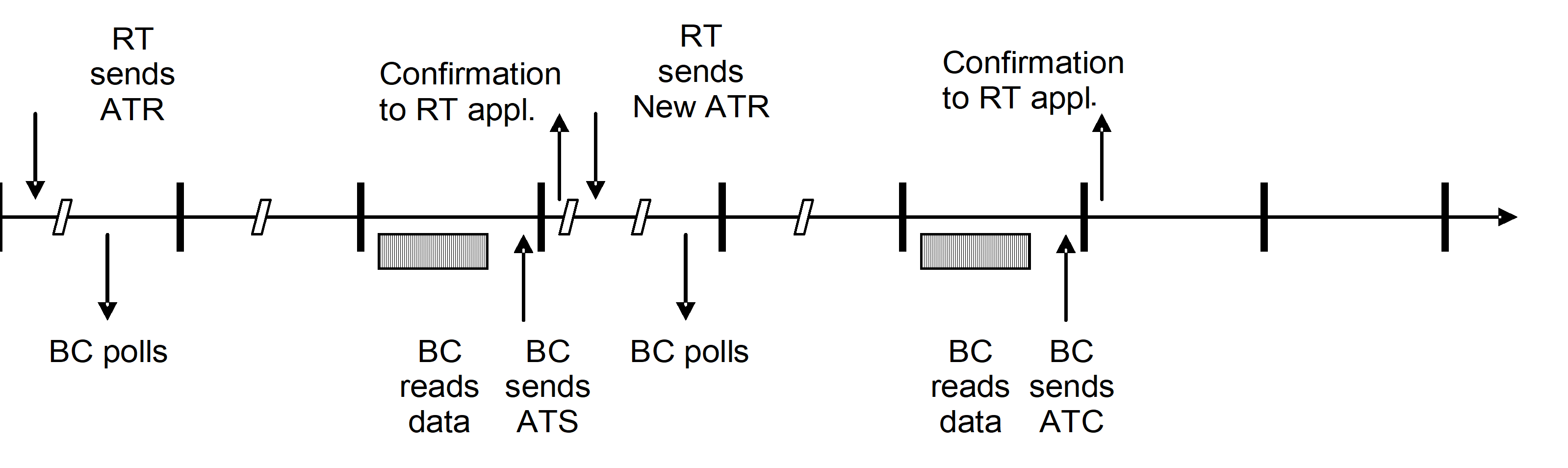 Figure 424: Data Acquisition timing with Best Effort QoS
In Figure 425, the timing for the Verified Length QoS is shown. With a zero gap the maximum performance from a single RT in this case is one user data block every fifth Communication Frame.
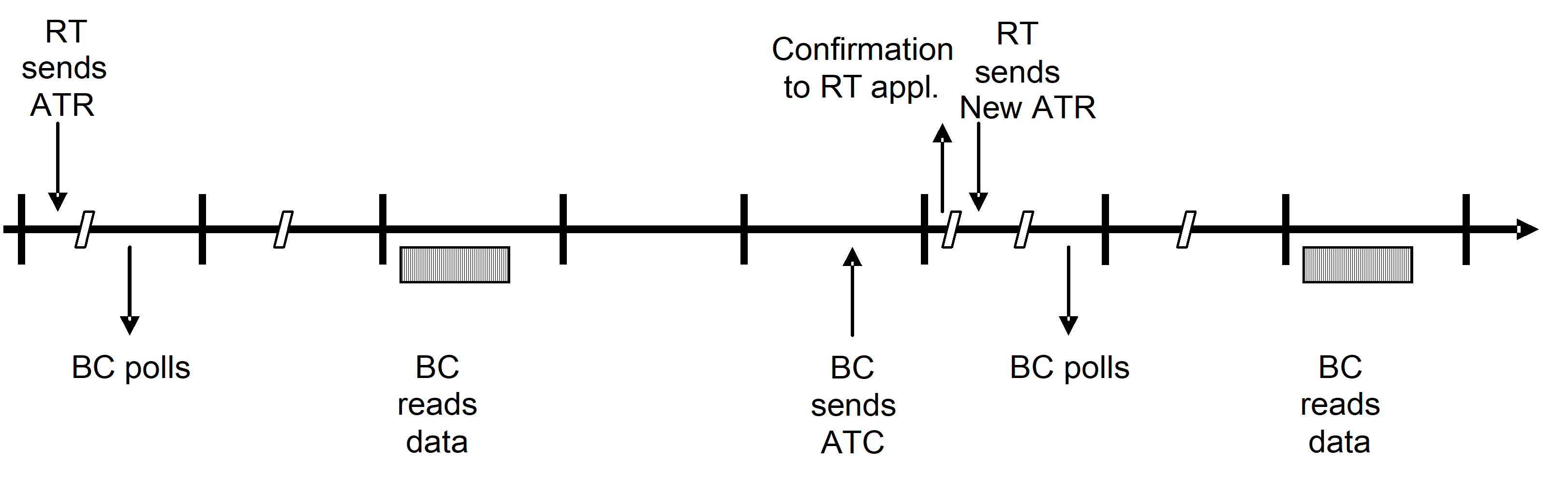 Figure 425: Data Acquisition timing with Verified Length QoS
Terminal Management services
Data bus management functions highly depend on the selected bus topology for a given mission and are therefore out of scope of this standard. However, the communication services and the 1553 message transfer level functions can provide information in support to the Data Management System applications such as the Failure Detection, Isolation and Recovery and the system’s configuration control.
The Terminal Management services provide data link layer harmonisation requirements for RT Health and Monitoring, Alarm Notification, Terminal Configuration and Data Wrap Around. The terminal management services use the Get Data and Set Data services.
The RT Health and Monitoring service provides the capability to receive information concerning the health of remote terminals across the bus. In particular, it covers the subsystem alarms that do not directly impact data.
The Alarm Notification service allows a RT to signal events to the Failure Detection Isolation and Recovery function of the bus management. In the MIL-STD-1553B standard, this is covered by the status bits:
Terminal Flag Bit concerning RT level problems;
Subsystem Flag Bit concerning RT subsystem, including SW for impact on the transferred data;
The Terminal Configuration service allows the user on BC to (re)configure the Remote Terminals.
The Data Wrap Around Service provides support to requirement defined in clause 30.7 of MIL-STD-1553B. It can be used to test one bus connection in support of FDIR.
Whereas the support of the Data Wrap Around service is mandatory for all RTs and BCs, the implementation of the RT Health Monitoring, Alarm Notification, and Terminal Configuration services can be a mission-specific choice, as well as details of these services. The way of implementing these services can also be driven by other (design) considerations for each individual communication device. For example, a simple RT without a processor inside may return only a small subset of RT status flags with valid information.
Physical Layer requirements
Overview
The physical layer of the 1553 data bus is specified in MIL-STD-1553B. This specification adds specific details about the physical layer, like more precise definition of the bus cable impedance, selection of the transformer-coupled stub connection, application of bus cable and stub discharge resistances and definition of the connector to be used between the terminals and the bus.
For the connectors there are three different configurations:
The first configuration is used for a single BC or RT and consists of two connectors with one bus in each connector. This configuration is used by units having a modular design where for instance nominal and redundant terminals are located on different modules with some physical separation. A typical example is a central spacecraft computer where each Bus Controller is located on different processor boards.
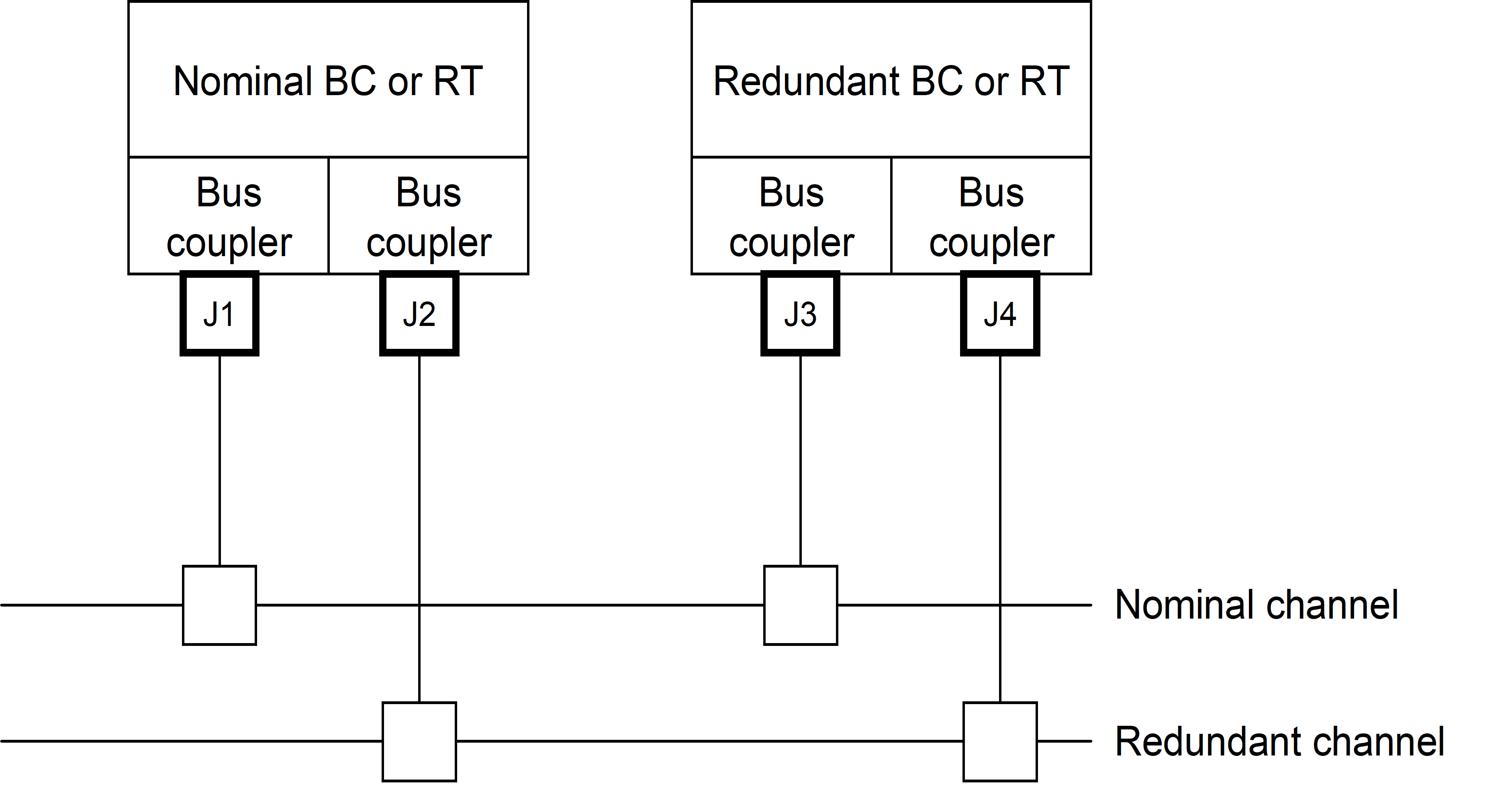 Figure 51: Bus connectors for separated BCs or RTs
The second configuration is used for an internally redundant BC or RT and consists of two connectors with two stubs belonging to one bus in each connector. This configuration is used by units where for instance nominal and redundant terminals are located the same physical module with almost no physical separation. A typical example can be a small internally redundant sensor where the space for connectors is limited.
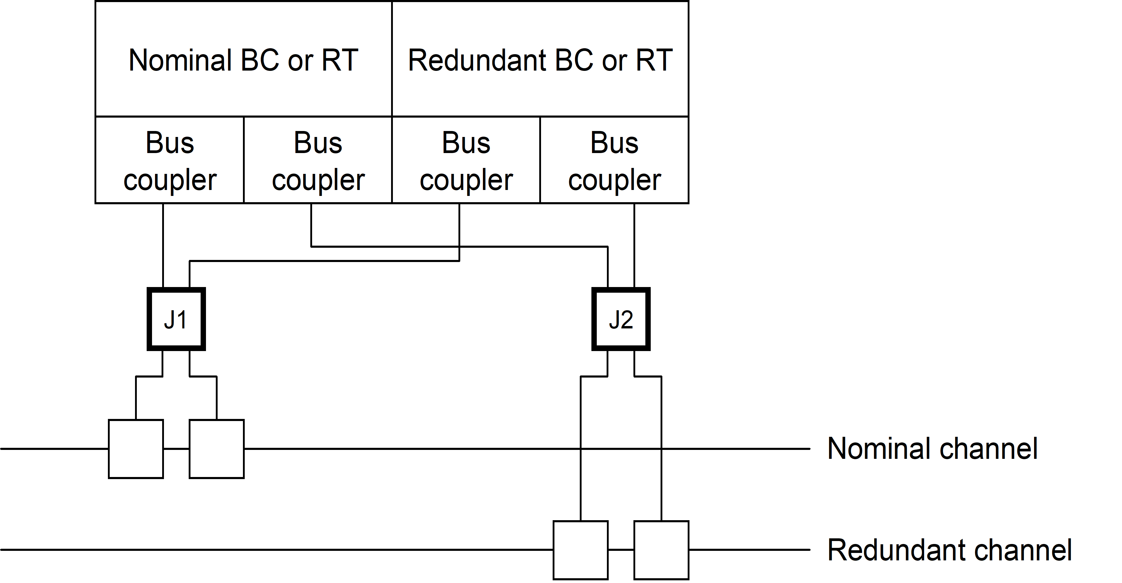 Figure 52: Bus connectors for integrated BCs or RTs
The third configuration is used by units connected to two separate buses that can be dual redundant and consists of two connectors with two stubs belonging to different buses in each connector. This configuration is used by units having a modular design where for instance nominal and redundant terminals are located on different modules with some physical separation but where each module is connected to two different buses. Typical examples are: a central spacecraft computer where two Bus Controllers are located on each processor board or an instrument control computer which acts as RT on one bus and BC on the other.
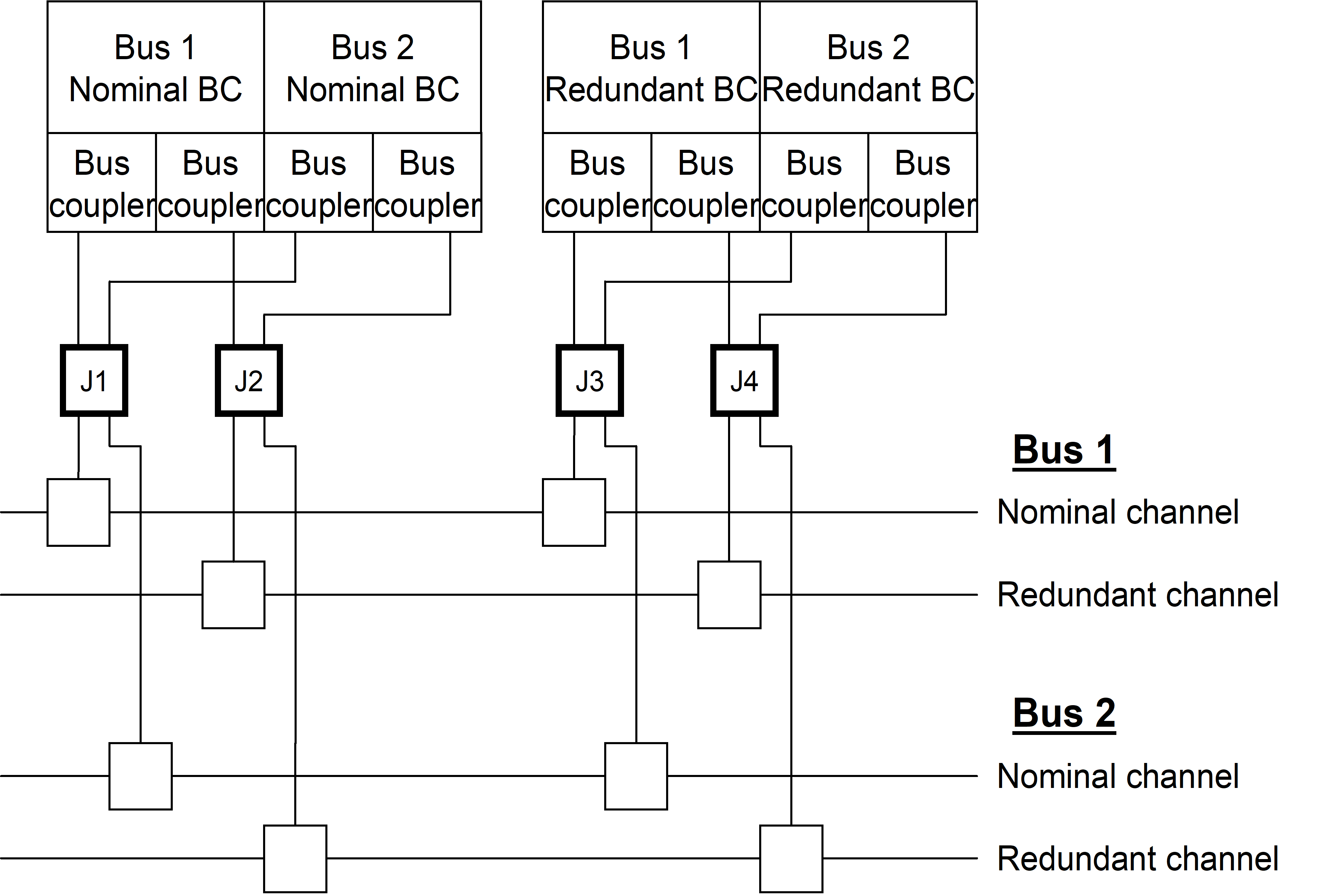 Figure 53: Bus connectors for separated BCs or RTs connected to dual buses
General
Physical layer requirements, which are not applicable to legacy devices, shall be identified and provided in an applicability matrix and statement of non-compliance.
Data bus characteristics
The data bus characteristics including stubs shall be in conformance with MIL-STD-1553B clauses 4.5.1, 30.10.1 and 30.10.2 with the following precisions:
- The data bus connection using transformer coupled stubs in conformance with MIL-STD-1553B Figure 9, with stub length not exceeding .
- The wire-to-wire distributed capacitance not exceeding 98 pF/m.
- The cable power loss not exceeding 1,5 dB/30 m at a sinusoidal frequency of 1 MHz. The nominal data bus cable characteristic impedance, identified in MIL-STD-1553B clauses 4.5.1.2, should be 75 with a variation of maximum 5 at a sinusoidal frequency of 1 MHz.
This ensures that the bus cables are compliant with ESA/SCC-3902-002.
A data bus cable wire shall have a resistance to the spacecraft chassis ground between 100 k and 100 M also in case of a single open circuit fault of a resistor or a cable wire.
A data bus stub wire shall have a resistance to the unit chassis ground between 100 k and 100 M also in case of a single open circuit fault of a resistor or a cable wire.
The data bus shall nominally be redundant and routing be in conformance with MIL-STD-1553B clause 4.6.2.
Optionally, non redundant data bus may be selected for specific applications.
Terminal characteristics
The characteristics of a bus terminal shall be in conformance with MIL-STD-1553B clause 4.5.2 and clause 30.10.6
The electrical isolation between buses shall be in conformance with MIL-STD-1553B clause 4.6.1.
The stub routing within a terminal shall be in conformance with MIL-STD-1553B clause 4.6.2.
Connectors
General
Any Stub connection to a terminal shall be made by either of:
- using 15-pole HDD pin connectors in conformance with ESCC 3401/001 or 3401/002 on the terminal unit.
- using 9-pole DEM pin connectors in conformance with ESCC 3401/001 or 3401/002 on the terminal unit.
The pin allocation for a Bus Controller shall be in conformance with Table 51 or Table 53.
The pin allocation for a Remote Terminal shall be in conformance with and Table 52 or Table 53.
TableTable 51: Pin allocation for 15-pin Bus Controller 1553 Bus Connector
|
Pin
|
Name
|
Pin
|
Name
|
Pin
|
Name
|
|
1
|
Stub 1
|
6
|
NC
|
11
|
Stub 1 Return
|
|
2
|
GND or NC
|
7
|
NC
|
12
|
GND or NC
|
|
3
|
GND or NC
|
8
|
NC
|
13
|
NC
|
|
4
|
GND or NC
|
9
|
NC
|
14
|
GND or NC
|
|
5
|
Stub 2
|
10
|
NC
|
15
|
Stub 2 return
|
|
NOTE 1 NC stands for no connection
| |||||
TableTable 52: Pin allocation for 15-pin Remote Terminal 1553 Bus Connector
|
Pin
|
Name
|
Pin
|
Name
|
Pin
|
Name
|
|
1
|
Stub 1
|
6
|
RT Address[4] MSB
|
11
|
Stub 1 return
|
|
2
|
GND
|
7
|
RT Address[3]
|
12
|
GND
|
|
3
|
GND
|
8
|
RT Address[2]
|
13
|
RT Address Parity
|
|
4
|
GND
|
9
|
RT Address[1]
|
14
|
GND
|
|
5
|
Stub 2
|
10
|
RT Address[0] LSB
|
15
|
Stub 2 return
|
|
NOTE 1 NC stands for no connection
| |||||
TableTable 53: Pin allocation for 9-pin Bus Controller or Remote Terminal 1553 Bus Connector
|
Pin
|
Name
|
Pin
|
Name
|
Pin
|
Name
|
|
1
|
Stub 1
|
4
|
NC
|
7
|
NC
|
|
2
|
NC
|
5
|
Stub 2
|
8
|
NC
|
|
3
|
NC
|
6
|
Stub 1 return
|
9
|
Stub 2 return
|
|
NOTE 1 NC stands for no connection
| |||||
Pin allocation for 15-pin
For Table 51 and Table 52, the RT address shall be obtained by connecting straps between an RT address or RT Address Parity signal and a GND signal such that:
- A logical “1” level is defined by an unconnected RT address signal.
- A logical “0” level is defined by a strap between the RT address signal and a GND signal.
For the case of a 9-pole connector no specific address connector is specified.
For Table 51 and Table 52, the current through a strap shall not exceed 1 mA also in a single parts fault case.
For Table 51 and Table 52, there shall be an odd number of straps.
It is then said that the parity is odd.
Pin allocation for remote terminal nominal bus
The pin allocation for remote terminal nominal bus shall be done in conformance with the configurations shown in Table 54.
For Table 54, for configurations 2 and 3, configuration 1 connector arrangement may be used.
Using configuration 1 connector arrangement for configuration 2 and 3 applications result in twice the amount of connectors.
For Table 54, the RT address shall be fully strapped in both connectors and the resulting address used by the RT shall be the AND of the two addresses.
This allows operating the RT regardless of the connector installed.
For Table 54, in case the unit contains only one RT pair, the RT B/D address pins shall be copies of the RT A/C address pins.
For Table 54, for legacy communication device may route nominal and redundant channel stubs in the same connector.
This routing violates the requirements in ECSS-E-ST-20 clause 4.2.1.d, and a waiver should be raised when this standard is applicable.
TableTable 54: Pin allocation for Remote Terminal nominal bus
|
Configuration
|
Stub 1 usage
|
Stub 2 usage
|
Address straps (15-poleconnector only)
| |
|
1 (BC) |
Single BC |
J1: Nominal channel J2: Redundant channel |
J1: Not used (5.5.2e) J2: Not used |
Not used |
|
1 (RT) |
Single RT(RT A) |
J1: Nominal channel J2: Redundant channel |
J1: Not used (5.5.2e) J2: Not used |
J1: RT A (5.5.2c) J2: RT A (5.5.2c) |
|
2 (BC) |
Internally redundant BC(BC A and BC B) |
J1: BC A Nominal channel J2: BC A Redundant channel |
J1: BC B Nominal channel J2: BC B Redundant channel |
Not used |
|
2 (RT) |
Internally redundant RT(RT A and RT B) |
J1: RT A Nominal channel J2: RT A Redundant channel |
J1: RT B Nominal channel J2: RT B Redundant channel |
J1: RT A J2: RT B |
|
3 |
Dual bus configurations(Bus 1 and Bus 2)with either of:- 4 BCs- 2 BCs and 2 RTs- 4 RTs |
J1: Bus 1 Nominal channel J2: Bus 1 Redundant channel J3: Bus 1 Nominal channel J4: Bus 1 Redundant channel |
J1: Bus 2 Nominal channel J2: Bus 2 Redundant channel J3: Bus 2 Nominal channel J4: Bus 2 Redundant channel |
J1: RT A J2: RT B (5.5.2d) J3: RT C J4: RT D (5.5.2d) |
Transmission method
Data shall be transmitted as words on the bus in conformance with MIL-STD-1553B clauses 4.3.3.1, 4.3.3.2, 4.3.3.3 and 4.3.3.4.
Data Link Layer requirements
General
Data link layer requirements, which are not applicable to legacy devices, shall be identified and provided in an applicability matrix and statement of non-compliance.
Data Words and Messages
Data word format
General
The data word formats shall be in conformance with MIL-STD-1553B clauses 4.3.3.5, 30.4 and 30.5.
Requirements in the following clause are precisions to this requirement.
Additional requirements to MIL-STD-1553B
Mode commands and mode codes
Mode commands shall be sent using subaddress 31.
The mode code usage shall be in conformance with:
- Mode code 0: Dynamic Bus Control.
Not recommended, but allowed for specific applications.
- Mode code 1: Synchronize.
Optional, if used to be used for time distribution as defined by this standard.
- Mode code 2: Transmit Status word.
Mandatory with usage in conformance with MIL-STD-1553B clause 4.3.3.5.1.7.3.
- Mode code 3. Initiate Self Test.
Not recommended for use.
- Mode code 4: Transmitter Shut Down.
Mandatory if a redundant bus is used with usage in conformance with MIL-STD-1553B clause 4.3.3.5.1.7.5.
- Mode code 5: Override Transmitter Shut Down.
Mandatory if a redundant bus is used with usage in conformance with MIL-STD-1553B clause 4.3.3.5.1.7.6.
- Mode code 6: Inhibit Terminal Flag.
Optional with usage in conformance with MIL-STD-1553B clause 4.3.3.5.1.7.7.
- Mode code 7: Override Inhibit Terminal Flag.
Optional with usage in conformance with MIL-STD-1553B clause 4.3.3.5.1.7.8.
- Mode code 8: Reset Remote Terminal.
This is optional. If used see 6.2.1.2.2.
- Mode code 16: Transmit Vector Word.
Optional, if used see 6.2.1.2.3.
- Mode code 17: Synchronize with Data Word.
Mandatory, to be used for communication synchronization as defined by this standard.
- Mode code 18: Transmit Last Command. Mandatory with usage in conformance with MIL-STD-1553B clause 4.3.3.5.1.7.13.
- Mode code 19: Transmit Built-in-Test Word.
Not recommended for use.
- Mode code 20: Selected Transmitter Shutdown.
Not recommended for use.
- Mode code 21: Override Selected Transmitter Shutdown.
Not recommended for use.
Mode code 8
If mode code 8 is used, the RT and the subsystem shall be reset to a power up initialised state within an application defined time.
If mode code 8 is used, while the RT is being reset it shall not respond to any valid command.
Mode code 16
If mode code 16 is used, the command shall only be sent as a result of a Service Request Bit set for the corresponding RT.
If mode code 16 is used, the content of the vector word shall be application dependant.
Non-recommended modes
If a mode code is not recommended for use, the BC shall not issue these commands.
If a mode code is not recommended for use, the RT shall react to the commands as specified in the corresponding paragraph of clause 4.3.3.5.1.7.1 in MIL-STD-1553B.
Terminal Status word
The Terminal Status Word bits usage shall be as follows:
- Bit time 9: Message Error Bit, mandatory with usage in conformance with MIL-STD-1553B clause 4.3.3.5.3.3.
- Bit time 10: Instrumentation Bit., which is set to “0”.
- Bit time 11: Service Request Bit.
Optional, if used see 6.2.1.2.5b.
- Bit times 12-14: Reserved and set to zero.
- Bit time 15: Broadcast Command Received Bit, mandatory with usage in conformance with MIL-STD-1553B clause 4.3.3.5.3.7.
- Bit time 16: Busy Bit. Not recommended for use.
A busy condition on an RT is a temporary situation that should not appear in nominal condition. RTs are discouraged from setting this bit.
- If the Busy bit is encountered by the BC, notify the condition to the BC application.
- Bit time 17: Subsystem Flag Bit. Optional, but if used, use it only be used to signal RT application errors.
- Bit time 18: Dynamic Bus Control Acceptance Bit. Not recommended, but allowed for specific applications.
- Bit time 19: Terminal Flag Bit. Optional, but if used, use it only be used to signal RT internal errors. If Bit time 11 is used, this bit shall be used by the RT application to signal an Alarm situation.
The alarm situation can be detailed through the transmission of a vector word if the “Transmit Vector Word” option is used.
Messages
The data words shall be combined into messages in conformance with MIL-STD-1553B clause 4.3.3.6, 4.3.3.7, 4.3.3.8, 4.3.3.9, 30.6 and 30.8 with the following precisions:
- the BC response timeout is selectable to a fixed value within the following ranges:
- 14 µs to 22 µs for applications without bus repeaters.
- 18 µs to 30 µs for applications with one bus repeater on a bus.
- RT to RT transfers are not used.
Terminal operation
Terminals operating as Bus Controllers, Remote Terminals or Bus Monitors shall operate in conformance with MIL-STD-1553B clause 4.4, 4.6.3 and 30.3.
Subaddress usage
The protocol elements defined in this standard shall be mapped on subaddresses as shown in Table 61.
- 1 For a given RT, all the unused SA of Table 61 can be used for the Get Data and Set Data services.
- 2 For units not following this standard concerning the Data Block Transfer Service the subaddress allocation can be different.
- 3 The subaddress allocation can differ for units which do not implement the services defined in clause 7
For a specific RT supporting the Data Block Transfer Service but not using all the reserved subaddresses for this service, the reserved subaddresses may be used for other purposes.
In case Time distribution service is not used, subaddress 29 shall not be used.
Subaddresses 0 and 8 shall not be used.
This allows for a bus monitor to uniquely differentiate Command Words from Status Words as the Instrumentation Bit is always ‘0’.
Message retries
The message retries in conformance with MIL-HDBK-1553A clause 50.6.2.1 “Automatic Retries” shall not be used.
TableTable 61: Subaddress allocation
|
Subaddress
|
Transmit
|
Receive
|
|
0
|
Not Used
|
Not Used
|
|
1
|
Health monitoring
|
Terminal Configuration
|
|
2
|
|
|
|
3
|
|
|
|
4
|
|
|
|
5
|
|
|
|
6
|
|
|
|
7
|
|
|
|
8
|
Not Used
|
Not Used
|
|
9
|
|
|
|
10
|
|
|
|
11
|
Acquisition Data Block
|
Distribution Data Block
|
|
12
|
Acquisition Data Block
|
Distribution Data Block
|
|
13
|
Acquisition Data Block
|
Distribution Data Block
|
|
14
|
Acquisition Data Block
|
Distribution Data Block
|
|
15
|
Acquisition Data Block
|
Distribution Data Block
|
|
16
|
Acquisition Data Block
|
Distribution Data Block
|
|
17
|
Acquisition Data Block
|
Distribution Data Block
|
|
18
|
Acquisition Data Block
|
Distribution Data Block
|
|
19
|
Acquisition Data Block
|
Distribution Data Block
|
|
20
|
Acquisition Data Block
|
Distribution Data Block
|
|
21
|
Acquisition Data Block
|
Distribution Data Block
|
|
22
|
Acquisition Data Block
|
Distribution Data Block
|
|
23
|
Acquisition Data Block
|
Distribution Data Block
|
|
24
|
Acquisition Data Block
|
Distribution Data Block
|
|
25
|
Acquisition Data Block
|
Distribution Data Block
|
|
26
|
Acquisition Data Block
|
Distribution Data Block
|
|
27
|
Distribution Transfer Confirmation
|
Distribution Transfer Descriptor
|
|
28
|
Acquisition Transfer Requests
|
Acquisition Transfer Confirmations
|
|
29
|
Received and current time
|
Time Message (optionally in broadcast mode)
|
|
30
|
Data wrap-around in conformance with MIL-STD-1553B clause 30.7
|
Data wrap-around in conformance with MIL-STD-1553B clause 30.7
|
|
31
|
Mode Code commands
|
Mode Code commands
|
Services definition
Time service
TimeData primitive
For TimeData primitive Table 71 shall apply.
TableTable 71: TimeData primitive definition
|
Function
|
The TimeData primitive is used by On-Board Time Master on the BC to distribute Time to all On-Board Time Slaves on RT’s.
| |
|
|
TimeData.Submit
|
TimeData.Deliver
|
|
When generated
|
At the BC, the TimeData.Submit is invoked by service-user to request service-provider to distribute Time to the peer service-users at the receiving ends
|
At the RT, the TimeData.Deliver is invoked by service-provider to deliver Time to service-user.
|
|
Effect on receipt
|
At the BC, receipt of TimeData.Submit primitive causes the service-provider to distribute Time to the peer service-users at the receiving ends.
|
At the RT, receipt of TimeData.Deliver primitive causes service-user to retrieve and store Time
|
|
Semantics
|
TimeData.Submit ( Time )
|
TimeData.Deliver ( Time )
|
|
Input parameter
|
Time – is the current time or time of the next Time Synchronization Message in case of usage of the TimeSynchronize primitive
|
None
|
|
Output parameter
|
None
|
Time – is the current time or time of the next Time Synchronization Message in case if TimeSynchronize primitive is also used
|
TimeSynchronize primitive
For TimeSynchronize primitive Table 72 shall apply.
TableTable 72: TimeSynchronize primitive definition
|
Function
|
The TimeSynchronize primitive is used by On-Board Time Master on the BC to distribute Time Synchronization Message to all On-Board Time Slaves on the RTs
| |
|
|
TimeSynchronize.Submit
|
TimeSynchronize.Deliver
|
|
When generated
|
At the BC, the TimeSynchronize.Submit is invoked by service-user to request service-provider to distribute Time Synchronization Message to the peer service-users at the receiving ends
|
At the RT, the TimeSynchronize.Deliver is invoked by service-provider to deliver Time Synchronization Message to service-user
|
|
Effect on receipt
|
At the BC, the TimeSynchronize.Submit primitive causes the service-provider to distribute Time Synchronization Message to the peer service-users at the receiving ends.
|
At the RT, receipt of TimeSynchronize.Deliver primitive causes service-user to update its local copy of the on-board time with respect to the Time value received by TimeData primitive
|
|
Semantics
|
TimeSynchronize.Submit ()
|
TimeSynchronize.Deliver ()
|
|
Input parameter
|
None
|
None
|
|
Output parameter
|
None
|
None
|
Communication Synchronization service
CommunicationSynchronize primitive
For CommunicationSynchronize primitive Table 73 shall apply.
TableTable 73: CommunicationSynchronize primitive definition
|
Function
|
The CommunicationSynchronize primitive is used by all on-board communication devices to synchronize their activities with respect to a common event: the Communication Frame Synchronization Message
| |
|
|
CommunicationSynchronize.Submit
|
CommunicationSynchronize. Deliver
|
|
When generated
|
At the BC, the CommunicationSynchronize.Submit is invoked by service-user to request service-provider to start periodic distribution of Communication Frame Synchronization Message to on-board service-users
|
The CommunicationSynchronize.Deliver is invoked by service-provider to notify service-user (on BC and on RTs) that Communication Frame Synchronization Message is sent
|
|
Effect on receipt
|
At the BC, receipt of CommunicationSynchronize.Submit primitive causes the service-provider to start periodic distribution of Communication Frame Synchronization Message
|
Receipt of CommunicationSynchronize.Deliver causes service-user to start synchronized activities (application dependant)
|
|
Semantics
|
CommunicationSynchronize.Submit ()
|
CommunicationSynchronize.Deliver (Communication Frame Number)
|
|
Input parameter
|
None
|
None
|
|
Output parameter
|
None
|
Communication Frame Number – is the number of the current Communication Frame
|
Set Data service
SendData primitive
For SendData primitive using pre-allocated bandwidth with populated content (predefined transfers, Type I), the Table 74 shall apply.
For SendData primitive using pre-allocated bandwidth with unpopulated content (Type II), the Table 75 shall apply.
TableTable 74: SendData primitive definition with predefined transfers (Type I)
|
Function
|
The SendData primitive is used by service-user (BC) to transfer data to a communicating peer on the (RT).
| |
|
|
SendData.Submit
|
SendData.Deliver
|
|
When generated
|
At the sending end (BC), the SendData.Submit is invoked by service-user to request service-provider to transfer data to the peer service-user at the receiving end (RT)
|
At the sending end (BC), the SendData.Deliver is invoked by service-provider to notify service-user of a data transfer completion.
|
|
Effect on receipt
|
At the sending end (BC), receipt of SendData.Submit primitive causes the service-provider to transfer data to the communicating peer (RT) using predefined transfers supported by the underlying Bus Profile
|
At the sending end (BC), receipt of SendData.Deliver primitive causes service-user to get notified of the transfer completion.
|
|
Semantics
|
SendData.Submit (SetData Id, Data)
|
SendData.Deliver ( CommunicationFrame Number )
|
|
Input parameter
|
SetData Id – identifier of the transfer carrying requested data within the Bus Profile
|
None
|
|
Output parameter
|
None
|
CommunicationFrame Number – is the number of the Communication Frame within which transfer of data took place
|
TableTable 75: SendData primitive definition with pre-allocated bandwidth (Type II)
|
Function
|
The SendData primitive is used by service-user (BC) to transfer data to communicating peer (RT).
| |
|
|
SendData.Submit
|
SendData.Deliver
|
|
When generated
|
At the sending end (BC), the SendData.Submit is invoked by service-user to request service-provider to transfer data to the peer service user at the receiving end (RT)
|
At the sending end (BC), the SendData.Deliver is invoked by service-provider to notify service-user of a data transfer completion.
|
|
Effect on receipt
|
At the sending end (BC), receipt of SendData.Submit primitive causes the service-provider to transfer data to the communicating peer (RT) using one of the pre-allocated bandwidth with unpopulated content supported by the underlying Bus Profile
|
At the sending end (BC), receipt of SendData.Deliver primitive causes service-user to get notified of the transfer completion
|
|
Semantics
|
SendData.Submit (Destination, Data, GroupID, SetDataId )
|
SendData.Deliver ( CommunicationFrame Number )
|
|
Input parameter
|
Destination – identifies address and subaddress of destination RT
|
None
|
|
Output parameter
|
SetData Id – identifier of the transfer carrying requested data within the Bus Profile
|
CommunicationFrame Number – is the number of the Communication Frame within which transfer of data took place
|
ReadStatus primitive
For ReadStatus primitive Table 76 shall apply.
TableTable 76: ReadStatus primitive definition
|
Function
|
The ReadStatus primitive is used by service-user (BC) to query status of a requested data transfer
|
|
|
ReadStatus.Submit
|
|
When generated
|
At the sending end (BC), the ReadStatus.Submit is invoked by service-user to request service-provider to provide status of a requested data transfer
|
|
Effect on receipt
|
At the sending end (BC), receipt of the ReadStatus.Submit primitive causes the service-provider to provide status of a requested data transfer.
|
|
Semantics
|
ReadStatus.Submit ( SetData ID, Status, NbNoResp )
|
|
Input parameter
|
SetData ID – is an identifier of the transfer carrying requested data within the Bus Profile
|
|
Output parameter
|
Status – OR of all status words of all corresponding 1553 transfers
|
Get Data service
ReceiveData primitive
For ReceiveData primitive using pre-allocated bandwidth with populated content (predefined transfers, Type I), the Table 77 shall apply.
For ReceiveData primitive using pre-allocated bandwidth with unpopulated content (Type II), the Table 78 shall apply.
TableTable 77: ReceiveData primitive definition with predefined transfers (Type I)
|
Function:
|
The ReceiveData primitive is used to initiate periodic data acquisition process from communicating peer (RT).
| |
|
|
ReceiveData.Submit
|
ReceiveData.Deliver
|
|
When generated
|
At the receiving end (BC), the ReceiveData.Submit primitive is invoked by service-user to request service-provider to start acquiring of data from the peer service-user at the receiving end (RT)
|
At the receiving end (BC), the ReceiveData.Deliver primitive is invoked by service-provider to notify service-user of a data acquisition completion.
|
|
Effect on receipt
|
At the receiving end (BC), receipt of ReceiveData.Submit primitive causes the service-provider to start transferring data to the communicating peer using predefined transfers supported by the underlying Bus Profile
|
At the receiving end (BC), receipt of ReceiveData.Deliver primitive causes service-user to be notified of the data acquisition completion
|
|
Semantics:
|
ReceiveData.Submit ( )
|
ReceiveData.Deliver (GetData Id)
|
|
Input parameter:
|
None
|
None
|
|
Output parameter:
|
None
|
GetDat Id – is identifier of the data transfer which carried requested data within the Bus Profile
|
|
|
NOTE: This primitive is implicit and is realised through CommunicationSynchronize.Deliver primitive of Communication Synchronization Service which initiates overall communication
|
NOTE: The ReceiveData.Deliver primitive can be an implicit primitive, which is realized through CommunicationSynchronize.Deliver primitive or can be an explicit primitive.
|
TableTable 78: ReceiveData primitive definition with pre-allocated bandwidth (Type II)
|
Function:
|
The ReceiveData primitive is used to initiate periodic data acquisition process from communicating peer (RT).
| |
|
|
ReceiveData.Submit
|
ReceiveData.Deliver
|
|
When generated
|
At the receiving end (BC), the ReceiveData.Submit primitive is invoked by service-user to request service-provider to start acquiring of data from the peer service-user at the receiving end (RT)
|
At the receiving end (BC), the ReceiveData.Deliver primitive is invoked by service-provider to notify service-user of a data acquisition completion.
|
|
Effect on receipt
|
At the receiving end (BC), receipt of ReceiveData.Submit primitive causes the service-provider to start transferring data to the communicating peer using one of the pre-allocated bandwidth with unpopulated content supported by the underlying Bus Profile
|
At the receiving end (BC), receipt of ReceiveData.Deliver primitive causes service-user to get notified of the data acquisition completion
|
|
Semantics:
|
ReceiveData.Submit (Source, GroupId, GetDataId )
|
ReceiveData.Deliver (GetDataId)
|
|
Input parameter:
|
Source – identifies address and subaddress of source RT
|
None
|
|
Output parameter:
|
GetDataId – is identifier of the data transfer which carried requested data within the Bus Profile
|
GetDat Id – is identifier of the data transfer which carried requested data within the Bus Profile
|
ReadData primitive
For ReadData primitive Table 79 shall apply.
TableTable 79: ReadData primitive definition
|
Function
|
This primitive is used to retrieve acquired data
|
|
|
ReadData.Submit
|
|
When generated
|
At the receiving end (BC), receipt of ReadData.Submit is invoked by service-user to request service-provider to retrieve acquired data
|
|
Effect on receipt
|
At the receiving end (BC), the ReadData.Submit primitive causes the service-provider to deliver acquired data to the service-user
|
|
Semantics
|
ReadData.Submit (GetData ID, Data, Status, NbNoResp)
|
|
Input parameter
|
GetData ID – is an identifier of the data transfer which carried requested data within the Bus Profile
|
|
Output parameter
|
Data –acquired data
|
Data Block Transfer Service
SendData primitive
For SendData primitive Table 710 shall apply.
TableTable 710: SendData primitive definition for the Data Block Transfer Service
|
Function
|
This primitive is used to initiate transfer of data from data source to the data destination.
| ||
|
|
SendData.Requestor.Submit
|
SendData.Acceptor.Deliver
|
SendData.Requestor.Deliver
|
|
When generated
|
At the sending end, the SendData.Submit primitive is invoked by service-user to request service-provider to transfer data to the peer service-user at the receiving end
|
At the receiving end, the SendData.Deliver primitive is invoked by service-provider to notify service-user of new data arrival.
|
At the sending end, the SendData.Deliver primitive is invoked by service-provider to notify service-user on comple-tion of data transfer as being confirmed by a peer service-user at the receiving end
|
|
Effect on receipt
|
At the sending end, receipt of SendData.Submit primitive causes the service-provider to notify the communicating peer on new data transfer request and start transferring data to it using next available Communi-cation Frame which is scheduled for this type of data transfer
|
At the receiving end, receipt of SendData.Deliver primitive causes service-user to get notified of the new data arrival
|
At the sending end, receipt of SendData.Deliver primitive causes service-user to get notified of the confirmed completion of a data transfer
|
|
Semantics
|
SendData.Submit (DestinationAddress, UserData, UserDataLength, QualityOfService)
|
SendData.Deliver (UserData, Status, NbNoResp)
|
SendData.Deliver (TransferCompleted, Status, NbNoResp)
|
|
Input parameter
|
DestinationAddress – identifies address and subaddress of destination RT
|
None
|
None
|
|
Output parameter
|
None
|
UserData – transferred data
|
TransferCompleted – Handshaking confirming completion of data transfer
|
|
NOTES
|
-
|
“NbNoResponse” and "Status" are only available for a user on a BC
|
“NbNoResponse” and "Status" are only available for a user on a BC
|
Protocol specification
Overview
This clause provides the requirements for the protocols applicable to the service data-link extension layer. It defines requirements applicable to:
Time Distribution and Time Synchronization service
Communication Synchronization service
Set and Get Data transfer services
Data Block Transfer service
Terminal Management services
Time service
Time Data primitive
BC requirements
The BC shall send Time Messages in conformance with the format in Table 81.
- 1 The P-field is defined in ECSS-E-ST-70-41 Annex on “Spacecraft time protocols”.
- 2 The standard CCSDS CUC format is requested for allowing greater interoperability between interconnected systems. Specific mission with local time generator in another format can deviate from this requirement.
For each mission a fixed value of the P-field shall be chosen.
If the P-field byte is indicating that less than seven bytes of time are valid, the unused bits shall be set to zero and unused words shall not be transmitted.
TableTable 81: Time Message data words, CCSDS CUC format
|
Word N°
|
Content
| |
|
0
|
‘0000 0000’
|
P-field
|
|
1
|
Time, values 231 - 216 s
| |
|
2
|
Time, values 215 - 20 s
| |
|
3
|
Time, values 2-1 - 2-16 s
| |
|
4
|
Time, values 2-17 – 2-24 s
|
‘0000 0000’
|
The BC shall send the Time Messages to subaddress 29.
This can be done individually to each RT using the service or in broadcast mode to all RTs.
When Time Synchronization is used the BC shall send the Time Messages before or during the second Communication Frame before the Time Synchronization Message corresponding to the time in the Time Message and at least 10 ms after the Time Synchronization Message corresponding to the previous Time Message.
The requirement implies that the BC always sends a Time Message before the first Time Synchronization Message is sent.
RT requirements
The RT shall copy the received Time Message to its output buffer in subaddress 29, starting from word 0 and filling the same number of words as were received, before the end of the Communication Frame following the Communication Frame in which the Time Message was received.
If words 3 or 4 were not received the corresponding words in the output buffer shall be set to zero.
The RT shall reserve words 5 – 9 of its output buffer of subaddress 29 for the host application to store the latest latched value of the local On-Board Time counter in the same format as is used for the Time Message.
In case no application data is stored, the words shall be zero.
The RT shall receive the Time Messages and generate TimeData.Deliver to its host application within an application selectable maximum time from the end of the Communication Frame in which the Time Message was received.
The end of a Communication Frame is defined as the end of the last bit in the received Communication Frame Synchronization Message.
Time Synchronize primitive
BC requirements
The BC shall send Time Synchronization Messages in the format of Synchronize (without data) mode commands.
The BC shall send the Time Synchronization Messages in broadcast mode.
The BC shall send Time Synchronization Messages as the result of invocation of TimeSynhcronize.Submit primitive determined by the BC host On-board Time function.
The nominal period of TimeSynchronizeSubmit shall be fixed for a mission.
Recommended value for TimeSynchronize.Submit Period is one second.
The variation of the nominal period of the Time Synch Requests shall be a mission specified parameter less than ±1%.
Frequency variations can occur when the Master OBT is adjusted by speeding up or down the clock rate to catch up with for instance an external reference. Such variations are assumed to last a few minutes only.
The BC shall start sending the Time Synchronization Message, by starting to transmit the synchronization field of the command word, within an application defined time from the TimeSynchronize.Submit.
This application defined time and its allowed jitter shall not be selected to have a jitter of less than 50 µs.
RT requirements
The RT shall receive the Time Synchronization Messages at frequencies and tolerances as defined by clauses 8.2.2.1d and 8.2.2.1e.
In case the Time Synchronization Messages arrive at points in time outside the specified range, this can be detected by the RT application and reported in the RT Health Data Word (refer to clause 8.7.2)
The RT shall receive the Time Synchronization Messages and generate Synchronize.Deliver to its host application within an application selectable maximum time from the end of the last bit of the received Time Synchronization Message.
This time and its allowed jitter is an application specific parameter but shall not be selected to have a jitter of less than 5 µs.
The RT application shall support the case when a Time Message precedes a Time Synchronization Message as well as the case when there is Time Synchronization Message without a preceding Time Message.
Communication Synchronization service
Requirements when the Time Synchronization service is implemented
BC requirements
The BC shall split the time between the start of two Time Synchronization Messages into N intervals, each interval housing a series of 1553 messages making up a Communication Frame.
N shall be a number between and including 2 and 256.
When synchronized, the Time Distribution Service requires a minimum of two Communication Frames.
The duration of each Communication Frame shall be selected by the BC to be either of:
- Equal duration for all Communication Frames.
- Equal duration for all Communication Frames except the last Communication Frame before the next Time Synchronization Message.
The BC shall support at least one of the methods provided in clause 8.3.1.1c.
In case equal duration for all Communication Frames is selected, the Communication Frame duration shall be variable ±1% by the BC to follow the variation of the Time Synchronization Messages.
In case equal duration for all Communication Frames except the last Communication Frame is selected, the duration of the last Communication Frame shall be adjustable by the BC to follow the variation of the Time Synchronization Messages.
The BC shall indicate the start of a frame by sending Communication Frame Synchronization Messages in the format of Synchronize with Data Word mode commands, except when coinciding with the Time Synchronization Message where this message replaces the Communication Frame Synchronization Message.
The BC shall send the Communication Frame Synchronization Messages in broadcast mode.
The BC shall start sending the Communication Frame Synchronization Message, by starting to transmit the synchronization field of the command word, within a fixed time from the time the BC signals the Communication Frame start to its application.
This fixed time is an application specific parameter.
The contents of the Data Word in the Communication Frame Synchronization Message generated by the BC shall be in conformance with Table 82.
TableTable 82: Communication Frame Synchronization Message Data Word
|
Bits N°
|
Content
|
|
0 – 7
|
Reserved for other services
|
|
8 – 15
|
Communication Frame number
|
The Communication Frame number shall be the frame following the frame starting with the Time Synchronization Message and incremented by one for each new Communication Frame until the next Time Synchronization Message.
The reserved field shall be set to zero in case it is not used.
RT requirements
The RT shall receive the Communication Frame Synchronization Messages or Time Synchronization Messages and generate Synchronization Indications including the Data Word if used by its host application within an application configurable maximum time from the time of request, i.e. the end of the last bit of the command word.
The RT shall write the latest received frame number in word 1 of subaddress 1 within an application specific time from reception of the current Frame Synchronization message.
The latest received frame number can be used by the Health Monitoring Service to detect RT loss of synchronization.
Requirements when the Time Synchronization service is not Implemented
BC requirements
The BC shall split the time into N equally long Communication Frames per second.
N shall be a number between and including 1 and 256.
The BC shall indicate the start of a frame by sending Communication Frame Synchronization Messages in the format of Synchronize with Data Word mode commands.
The BC shall send the Communication Frame Synchronization Messages in broadcast mode.
The BC shall start sending the Communication Frame Synchronization Message, by starting to transmit the synchronization field of the command word, within a fixed time from the time the BC signals the Communication Frame start to its application.
This fixed time is an application specific parameter.
The contents of the Data Word in the Communication Frame Synchronization Message generated by the BC shall be in conformance with Table 82.
The Communication Frame number shall be the first frame and incremented by one modulo N for each new Communication Frame.
The reserved field shall be set to zero in case it is not used by other services.
RT requirements
The RT shall receive the Communication Frame Synchronization Messages and generate Synchronization Indications including the Data Word to its host application within an application defined maximum time from the time of request, i.e. the end of the last bit of the command word.
The RT shall write the latest received frame number in word 1 of subaddress 1 within an application specific time from reception of the current Frame Synchronization message.
The latest received frame number is used by the Health Monitoring Service to detect RT loss of synchronization.
BC Requirements for Accurate Message Transfer (optional)
The BC shall provide a capability allowing each message to be transferred during a Communication Frame to have its transmission start time fixed relative to the start of the frame, defined by the middle transition of the synchronization field of the command word.
This allows for a deterministic scheduling of all transfers made on the bus.
The precision of the delay between the frame start time and the message start time, defined by the middle transition of the synchronization field of the command word, shall be better than ±0,1% or ± 100 µs, whatever is the largest.
This performance requirement is intended to allow the use of a moderate stability oscillator in communication devices without giving too stringent requirements for the precision of short delays.
The BC shall provide a set of fixed bandwidth allocation schemes.
This implies that there cannot be a change of position of a scheduled transfer within a frame in case of varying usage of bandwidth from other transfers.
Set Data service
BC requirements
The BC shall send any integral number of 1553 message words greater than zero up to a limit which is an application defined value.
This limit can be higher than 32 words, the only constraint being the completion of all transfers before next Communication Frame as per clause 8.4.1c
The transfers resulting from an invocation of the Set Data service shall take place at the earliest after the start of the next Communication Frame.
All transfers resulting from an invocation of the Set Data service shall be completed within one Communication Frame.
In case of transmission error in one or more transfers resulting from an invocation of the Set Data service, details about the error(s) shall be available to the user through corresponding Status Words.
RT Requirements
There is no requirement at the RT level for this service. The indication of the availability of data is ensured through usage of the Communication Synchronization Service.
Get Data service
BC requirements
The BC shall retrieve any integral number of 1553 message words greater than zero up to a limit which is an application defined value.
This limit can be higher than 32 words, the only constraint being the completion of all transfers before next Communication Frame as per clause 8.5.1c.
The transfers resulting from an invocation of the Get Data service shall take place at the earliest after the start of the next Communication Frame.
Synchronization for data access within RT is insured by predefined Bus Profile and RT data refresh time.
All transfers resulting from an invocation of the Get Data service shall be completed within one Communication Frame.
In case of transmission error in one or more transfers resulting from an invocation of the Get Data service, details about the error(s) shall be available to the user through corresponding Status Words.
RT requirements
The RT shall refresh data in the output data buffers within an application dependant fixed time after a Communication Frame Synchronization message.
This requirement insures integrity of data to be retrieved.
Data Block Transfer service
Data Distribution requirements (BC to RT transfer)
BC requirements
A Reset Data Block Transfer Service command, consisting of a Distribution Transfer Descriptor as defined in clause 8.6.1.1e, shall be sent to each RT using this service before the first time the service is used, or if needed otherwise.
This requirement aims at ensuring a deterministic start-up condition and a clear condition in case of restart due to for instance a terminal reconfiguration.
The BC can acquire the Distribution Transfer Confirmation but not earlier than the second Communication Frame after a Distribution Transfer Descriptor has been sent to a certain RT, and check that the protocol reset has been accepted by the RT.
If the reset has not been accepted, the BC shall notify its application about the missing acceptance.
A data distribution transfer shall consist of the BC transmitting a Distribution Data Block followed by a Distribution Transfer Descriptor and possibly the BC reading a Distribution Transfer Confirmation.
TableTable 83: Layout of the Distribution Transfer Descriptor (BC to RT, SA 27R)
|
1. Data word (Distribution Data size)
|
2. Data word (Distribution Control)
| |||||
|
( 4 Bit)
|
(12 Bit)
|
( 1 Bit)
|
( 1 Bit)
|
( 1 Bit)
|
( 5 Bit)
|
( 8 Bit)
|
|
Reserved
|
Number of bytes for thecurrent data block (SIZE)
|
QoS
|
Reset
|
Mode
|
SA
|
DistributionBlock Count (DBC)
|
The Distribution Transfer Descriptor message layout shall be in conformance with Table 83 with the following meaning:
- Reserved bits all set to zero.
These bits are reserved for future use.
- Number of bytes for current Distribution Data Block:
- A field value of zero to be interpreted as 4096.
This data field indicates the number of used bytes in the Distribution Data Block.
* An odd number to indicate that the least significant byte of the last word of the last message contains a Filler Octet.
- 1 This Filler Octet is generated by the sender, when splitting a user data block into 1553-messages.
- 2 The Filler-octet can contain any data.
- If the Reset flag is ‘1’ this field to be set to zero.
- QoS - Quality of Service: If the Reset flag is ‘1’, this field to be set to ‘0’.
A ‘0’ in this field indicates that the Distribution Data Block is transferred with Best Effort. A ‘1’ in this field indicates that the Distribution Data Block is transferred with Verified Data Length.
- Reset:
- A ‘0’ in this data field to indicate that the protocol carries on.
- A ‘1’ in this data field to indicate that the protocol with this RT is reset.
- Mode:
- A ‘0’ in this data field to indicate that multiple subaddresses are used to transfer the data.
- A ‘1’ in this data field to indicate that a single subaddress is used.
- If the Reset flag is ‘1’, this field to be set to ‘0’.
- SA:
- In case the Mode flag is ‘1’ this data field is used to indicate to which subaddress data are written.
- In case the Mode flag is ‘0’, this field to be set to ‘01011’, showing SA11.
- Distribution Block Count:
This field is a circular 8-bit-counter, identifying the current data block.
* To be provided by the BC, independently for each Remote Terminal Address, for Distribution Data Block identification within the Transfer Layer.
* If the Reset flag is ‘1’, the Distribution Block Count for the selected RT to be set to zero.
* At the first transfer after a protocol reset, the Distribution Block Counter for the selected RT to be set to 1.
* For each new transfer to be carried out the Distribution Block Count to be incremented by one and when it reaches 255 the next count number to be 1.
- 1 In case the service user performs a retry of the same data block the count is still incremented as the service does not differentiate retries from new transfers.
- 2 By using a counter, which is incremented with every new request, and which is returned to the BC after a successful transfer, the BC is able to detect the completion of a specific Distribution Transfer, even if successive distribution data blocks are identical (in size or contents).
- 3 To avoid that after a BC initialisation or reset an identical value to the previous one is used for the Distribution Block Count, there is one fixed value foreseen for that case. This value does never appear in any other transfer, it is skipped in the normal sequence of distributions, when this counter wraps around.
The Distribution Transfer Descriptor (DTD) shall be sent to the RT in SA 27R.
If the Mode flag is ‘0’ the Distribution Data Block shall be: - sent to Distribution Data Receive SAs of the destination RT, beginning with SA 11R.
- segmented into a number of 1553 messages of maximum size, i.e. 32 words, with the first 64 bytes of the block sent to SA11R, the next 64 bytes sent to SA12R etc.
The last message (see requirement 8.6.1.1g), or a single message if the data block contains 64 bytes or less, may be shorter.
The last message (see requirement 8.6.1.1g), or a single message if the data block contains 64 bytes or less, shall transfer what remains of the data block including a possible single Filler Octet.
If the Mode flag is ‘1’ the Distribution Data Block shall be - sent to the Receive SA of the destination RT as specified by the Distribution Transfer Descriptor, and
- segmented into a number 1553 messages of maximum size, i.e. 32 words, with the first 64 bytes of the block sent to the selected SA, the next 64 bytes sent to the same SA etc.
The last message (see requirement 8.6.1.1j), or a single message if the data block contains 64 bytes or less, may be shorter.
The last message (see requirement 8.6.1.1j), or a single message if the data block contains 64 bytes or less, shall transfer what remains of the data block including a possible single Filler Octet.
The transfers resulting from a Distribution Data Block followed by its Distribution Transfer Descriptor message (DTD) shall be completed within one Communication Frame.
If the QoS flag is ‘1’ the BC shall acquire the Distribution Transfer Confirmation not earlier than the second Communication Frame after a Distribution Transfer Descriptor has been sent to a certain RT.
If the QoS flag is ‘1’ the BC shall check the Error flag and the Distribution Block Count of the received Distribution Transfer Confirmation.
If the Error flag is ‘0’ and the Distribution Block Count of the received Distribution Transfer Confirmation is equal to the Distribution Block Count of the last transmitted Distribution Transfer Descriptor, the reception of the Distribution Data Block shall be declared confirmed.
If the Error flag is ‘1’ and the Distribution Block Count of the received Distribution Transfer Confirmation is equal to the Distribution Block Count of the last transmitted Distribution Transfer Descriptor, a Transfer Length Error shall be reported to the user of the service.
If the Distribution Block Count of the received Distribution Transfer Confirmation is not equal to the Distribution Block Count of the last transmitted Distribution Transfer Descriptor, a Protocol Error shall be reported to the user of the service.
It is the responsibility of the service user to decide whether to perform a transmission retry or not. If a retry is attempted, this is treated as a new transmission by this protocol.
RT requirements
The RT shall receive the Distribution Data Block, evaluate the Distribution Transfer Descriptor and maintain a Distribution Transfer Confirmation.
Within the Communication Frame following the frame in which the Distribution Transfer Descriptor as defined in 8.6.1.2.c is received, the RT shall perform the following:
- If the Reset flag is ‘0’ and the Mode flag indicates a transfer mode supported by the RT, compare the Distribution Data Count from the received DTD with the Distribution Data Count of the current Distribution Transfer Confirmation as follows:
- If a difference is found and if the QoS flag is ‘0’, the associated Distribution Data Block be accepted (new Distribution Data, new command) and the Distribution Transfer Confirmation be updated with the Error and Reset flags cleared.
- If a difference is found and if the QoS flag is ‘1’ and the number of correctly received bytes does match the number of bytes in the Distribution Transfer Descriptor, the associated Distribution Data Block be accepted (new Distribution Data, new command) and the Distribution Transfer Confirmation be updated with the Error and Reset flags cleared.
- If a difference is found and if the QoS flag is ‘1’ and the number of correctly received bytes does not match the number of bytes in the Distribution Transfer Descriptor, ignore the distribution data block, the Distribution Transfer Confirmation being updated with the Error flag set and the Reset flag reset.
The RT may optionally report the failure to the user of the service within the RT-unit.
* If no difference is found, ignore the associated Distribution Data Block (no new data) and keep the Distribution Transfer Confirmation unchanged.
It is not necessary that the Distribution Data Counter has been incremented by only one. Any new data (command) can be accepted.
- If the Reset flag is ‘0’ and the Mode flag indicates a transfer mode that is not supported by the RT the associated Distribution Data Block is ignored (no new data) and the Distribution Transfer Confirmation unchanged.
- If the Reset flag is ‘1’ the Distribution Transfer Confirmation is updated with the Reset flag set to indicate that a protocol reset has been carried out. TableTable 84: Layout of the Distribution Transfer Confirmation (BC to RT, SA 27T)
|
1. Data word (Distribution Data size)
|
2. Data word (Distribution Control)
| |||||
|
( 4 Bit)
|
(12 Bit)
|
( 1 Bit)
|
( 1 Bit)
|
( 1 Bit)
|
( 5 Bit)
|
( 8 Bit)
|
|
Reserved
|
Number of bytes for thecurrent data block (SIZE)
|
Error
|
Reset
|
Mode
|
SA
|
DistributionBlock Count (DBC)
|
The Distribution Transfer Confirmation message layout shall be in conformance with Table 84 with the following meaning:
- Reserved bits: all set to zero.
These bits are reserved for future use.
- Number of bytes for current Distribution Data Block:
- This data field to be a copy of the corresponding data received in the Distribution Transfer Descriptor.
- After an RT reset, to be set to zero.
- Error:
- A ‘0’ in this data field to indicate that no errors were detected.
- A ‘1’ in this data field to indicate that an incorrect number of bytes have been received.
- After an RT reset or a protocol reset, this bit to be ‘0’.
- Reset:
- A ‘0’ in this data field to indicate that the protocol carries on.
- A ‘1’ in this data field to indicate that a protocol reset or an RT reset has been carried out.
- Mode:
- This data field to be a copy of the Mode flag received in the Distribution Transfer Descriptor.
- After an RT reset, to be set to ‘0’.
- SA:
- This data field to be a copy of the corresponding data received in the Distribution Transfer Descriptor.
- After an RT reset, to be set to zero.
- Distribution Block Count:
- This data field to be a copy of the corresponding data received in the Distribution Transfer Descriptor.
- After an RT reset this field to be set to zero.
If accepted data have arrived, the RT shall deliver the data block to the service destination user, stripping off any Filler Octet.
If the Mode flag of the Distribution Transfer Descriptor is ‘0’ the data shall be assembled from the structure written by the BC as defined in clause 8.6.1.1g.
If the Mode flag of the Distribution Transfer Descriptor is ‘1’ the data shall be assembled from the structure written by the BC as defined in clause 8.6.1.1j.
Data Acquisition requirements (RT to BC transfer)
BC requirements
A data acquisition transfer shall consist of the BC polling an RT Acquisition Transfer Request as defined in clause 8.6.2.2d. for possible available data followed by the BC acquiring a data block and transmitting an Acquisition Transfer Confirmation.
The BC shall maintain, for each Remote Terminal Address using the protocol, an Acquisition Block Counter value of the last Acquisition Data Block received.
At BC initialisation or restart, all maintained Acquisition Block Counters for all RTs shall be set to 0 and an Acquisition Protocol Reset Request shall be sent to each RT using the protocol in conformance with clause 8.7.3h.
When an Acquisition Protocol Reset Request has been sent to an RT, the BC shall not poll the Acquisition Transfer Request of that RT earlier than the second Communication Frame following the Communication Frame in which the reset was sent.
At latest during the second Communication Frame before the next Acquisition Transfer for a certain RT is scheduled, the BC shall poll the RT for a need of transfer or a protocol reset.
The poll of the RT for a need of transfer shall be done by reading the RT Acquisition Transfer Request message from SA 28T.
If the Reset flag is ‘0’, the BC shall identify a new Acquisition Transfer Request by evaluation of the Acquisition Block Count value with comparison to the stored one and do the following:
- If these values are not identical:
- acquire the block using subaddresses as defined in clause.8.6.2.2g, in case the Mode flag in the Acquisition Transfer Request is ‘0’ and the SIZE field indicates a block length between 1 and 1024 in the BC.
- ignore the request, in case the Mode flag in the Acquisition Transfer Request is ‘0’ and the SIZE field indicates a block length greater than the BC.
- acquire the block using subaddresses as defined in clause 8.6.2.2j in case the Mode flag in the Acquisition Transfer Request is ‘1’.
- If these values are identical, ignore the request (no new data).
If the Reset flag is ‘1’ the BC shall send an Acquisition Transfer Confirmation with the Reset bit set to ‘1’ to indicate that a protocol reset is granted and has been carried out on the BC side. The Acquisition Transfer Confirmation shall be sent during the second Communication Frame, which follows the Communication Frame in which the acquisition was carried out.
If the QoS flag is ‘0’ or the QoS flag is ‘1’ and data have been acquired without transmission errors, the BC shall: - deliver the user data to the BC service destination user, stripping off any Filler Octet.
- update the stored Acquisition Block Counter with the value of the received Acquisition Data Count.
- send an Acquisition Transfer Confirmation with this updated Acquisition Block Count and the Error flag set to ‘0’ to SA 28R of the RT.
- in case the QoS flag is ‘0’, send the Acquisition Transfer Confirmation within the same Communication Frame in which the acquisition was carried out.
- in case the QoS flag is ‘1’, send the Acquisition Transfer Confirmation at the latest during the second Communication Frame, which follows the Communication Frame in which the acquisition was carried out. If the QoS flag is ‘1’ and data have been acquired with transmission errors, the BC shall:
- update the stored Acquisition Block Counter with the value of the received Acquisition Data Counter.
- send an Acquisition Transfer Confirmation with this updated Acquisition Block Counter and the Error flag set to ‘1’ to SA 28R of the RT.
The BC can optionally report the failure to the user of the service within the BC unit.
- send the Acquisition Transfer Confirmation at the latest during the second Communication Frame, which follows the Communication Frame in which the acquisition was carried out. TableTable 85: Layout of the Acquisition Transfer Confirmation, ATC (BC to RT, SA 28R)
|
1. Data word (Acquisition Data size)
|
2. Data word (Acquisition Control)
| |||||
|
( 4 Bit)
|
(12 Bit)
|
( 1 Bit)
|
( 1 Bit)
|
( 1 Bit)
|
( 5 Bit)
|
( 8 Bit)
|
|
Reserved
|
Number of bytes for thecurrent data block (SIZE)
|
Error
|
Reset
|
Mode
|
SA
|
AcquisitionBlock Count (ABC)
|
The layout of the Acquisition Transfer Confirmation shall be in conformance with Table 85 with the following meaning:
- Reserved bits: all to be set to zero.
These bits are reserved for later use.
- Number of bytes for next Acquisition Data Block: to be a copy of the corresponding data in the Acquisition Transfer Request acquired from the RT.
- Error:
- A ‘0’ in this data field to indicate that the transfer was successfully completed.
- A ‘1’ in this data field to indicate that the data was transferred with errors.
- After a protocol reset, set this bit to ‘0’.
- Reset:
- A ‘1’ in this data field to indicate that a protocol reset request is granted.
- A ‘0’ in this data field to indicate that the protocol carries on.
- Mode: to be a copy of the Mode flag in the Acquisition Transfer Request acquired from the RT.
- SA: to be a copy of the corresponding data received in the Distribution Transfer Descriptor.
- Acquisition Block Count: to be a copy of the corresponding data in the Acquisition Transfer Request acquired from the RT.
RT requirements
A Reset Data Block Transfer Service request, consisting of an Acquisition Transfer Request as defined in clause 8.6.2.2.d with the Reset flag set to ‘1’, shall be sent by each RT using this service before the first time the service is used, or if needed otherwise.
This requirement aims at ensuring a deterministic startup condition and a clear condition in case of restart due to for instance a terminal reconfiguration.
Before a request for an Acquisition Transfer to the BC is made, the RT shall update its data buffers associated with Acquisition Transfers with new messages, in conformance with clause 8.6.2.2.g. or clause 8.6.2.2.j, depending on the transfer modes that are supported by the RT.
In order to indicate a request for an Acquisition Transfer to the BC, the RT shall update its Acquisition Transfer Request, ATR, in a buffer associated with SA 28T.
TableTable 86: Layout of the Acquisition Transfer Request, ATR (RT to BC, SA 28T)
|
1. Data word (Acquisition Data size)
|
2. Data word (Acquisition Control)
| |||||
|
( 4 Bit)
|
(12 Bit)
|
( 1 Bit)
|
( 1 Bit)
|
( 1 Bit)
|
( 5 Bit)
|
( 8 Bit)
|
|
Reserved
|
Number of bytes for thecurrent data block (SIZE)
|
QoS
|
Reset
|
Mode
|
SA
|
AcquisitionBlock Count (ABC)
|
The Acquisition Transfer Request shall be in conformance with Table 86 with the following meaning:
- Reserved bits: all to be set to zero.
These bits are reserved for future use.
- Number of bytes for next Acquisition Data Block:
- This data field to indicate the number of bytes in the Acquisition Data Block.
- A field value of zero to be interpreted as 4096.
- An odd number to indicate that the least significant byte of the last word of the last message contains a Filler Octet.
- 1 This Filler Octet is generated by the sender, when splitting a user data block into 1553-messages.
- 2 The Filler-octet can contain any data.
- If the Reset flag is ‘1’ this field to be set to zero.
- QoS - Quality of Service:
- A ‘0’ in this field to indicate that the Distribution Data Block is transferred with Best Effort.
- A ‘1’ in this field to indicate that the Distribution Data Block is transferred with Verified Data Length.
- If the Reset flag is ‘1’ this field to be set to ‘0’.
- Reset:
- A ‘0’ in this data field to indicate that the protocol carries on.
- A ‘1’ in this data field to indicate that a protocol reset is requested or that the RT has been reset.
- Mode:
- A ‘0’ in this data field to indicate that multiple subaddresses are used to transfer the data.
- A ‘1’ in this data field to indicate that a single subaddress is used.
- If the Reset flag is ‘1’ this field to be set to ‘0’.
- SA:
- In case the Mode flag is ‘1’ this data field to indicate to which subaddress data are written.
- In case the Mode flag is ‘0’ this field to be ‘01011’, showing SA 11.
- Acquisition Block Count:
This field is a circular 8-bit-counter, identifying the current data block.
* If the Reset flag is ‘1’ the Acquisition Block Count to be set to zero.
* At the first transfer after a protocol reset, the Acquisition Block Count to be set to 1.
* For each new transfer to be carried out the ABC to be incremented by one and when the ABC reaches 255 the next count number to be 1.
- 1 In case the service user performs a retry of the same data block the count is still incremented as the service does not differentiate retries from new transfers
- 2 By using a counter, which is incremented with every new request, and which is returned to the RT after a successful transfer, the RT is able to detect the completion of a specific Acquisition Transfer, even if successive acquisition data blocks are identical (in size or contents).
- 3 To avoid that after an RT initialization or reset an identical value to the previous one is used for the Acquisition Block Count, there is one fixed value foreseen for that case. This value does never appear in any other transfer, it is skipped in the normal sequence of acquisitions, when this counter wraps around.
When the RT is polled for a Request, the ATR shall be consistent. - 1 With consistent means that the two words belong to the same request and that the RT treats the two words as a single 32-bit entity.
- 2 The actual acquisition transfer is transparent for a RT, i.e. there is no guarantee that a certain data block is acquired immediately after placing a request. However, the RT is notified following a certain acquisition, that the acquisition has taken place.
The RT may generate a new Acquisition Transfer Request only after occurrence of one of the following conditions: - After a protocol reset.
- Reception of an Acquisition Transfer Confirmation with the same Acquisition Block Count as the currently outstanding Acquisition Transfer Request.
In case the RT does not receive any Acquisition Transfer Confirmation within the expected time it is the responsibility of the RT application to maintain a timeout and to request a protocol reset before any new transfer request is made.
If the Mode flag is ‘0’ the Acquisition Data Block shall:
- be available in the Acquisition Data Transmit SAs of the source RT, beginning with SA 11T.
- segmented into a number of 1553 messages of maximum size, i.e. 32 words, with the first 64 bytes of the block in SA 11T, the next 64 bytes in SA 12T etc.
The last message (see requirement 8.6.2.2.g), or a the single message if the data block contains 64 bytes or less, may be shorter and
The last message (see requirement 8.6.2.2.g), or a the single message if the data block contains 64 bytes or less, shall contain what remains of the data block including a possible single Filler Octet.
If the Mode flag is ‘1’ the Acquisition Data Block shall be: - available in the Transmit SA of the source RT as specified by the Acquisition Transfer Request.
- segmented into a number of 1553 messages of maximum size, i.e. 32 words, with the first 64 bytes of the block available in the selected SA, the next 64 bytes in the same SA etc.
The last message (see requirement 8.6.2.2.j), or a the single message if the data block contains 64 bytes or less, may be shorter and
The last message (see requirement 8.6.2.2.j), or a the single message if the data block contains 64 bytes or less, shall transfer what remains of the data block including a possible single Filler Octet.
When there is an outstanding transfer request or protocol reset request, the RT shall check the Acquisition Transfer Confirmation after each Communication Frame Synchronization Message and perform the following: - signal its service user that the protocol reset is completed, if the Reset flag is ‘1’.
- signal its service user that the transfer is completed, if the Acquisition Block Count of the Acquisition Transfer Confirmation is identical to the Acquisition Block Count of the currently outstanding Acquisition Transfer Request and the QoS flag is ‘0’.
- signal its service user that the transfer is successful, if the Acquisition Block Count of the Acquisition Transfer Confirmation is identical to the Acquisition Block Count of the currently outstanding Acquisition Transfer Request and the QoS flag is ‘1’ and the Error flag of the Acquisition Transfer Confirmation is ‘0’.
- signal its service user that the transfer is unsuccessful, if the Acquisition Block Count of the Acquisition Transfer Confirmation is identical to the Acquisition Block Count of the currently outstanding Acquisition Transfer Request and the QoS flag is ‘1’ and the Error flag of the Acquisition Transfer Confirmation is ‘1’.
Terminal Management services
RT monitoring
The Get Data service shall be used for acquisition of the RT health and monitoring data.
RT_Health data shall be stored in the first transmit word of SA 1T in conformance with Table 87.
TableTable 87: SA 1T: RT_Health & Monitoring data definition
|
Word N°
|
Data
|
|
0
|
RT_Health data word
|
|
1
|
Latest received Communication Frame number (c.f. 8.3.1.2b and 8.3.2.2b)
|
|
2……14
|
RT_Health & Monitoring data
|
|
15……31
|
RT configuration monitoring data
|
Word 2 to 15 of SA 1T shall be reserved for RT Health and monitoring complementary data to be defined by the application.
Word 16 to 32 of SA 1T shall be reserved for RT configuration monitoring data to be defined by the application.
If not used by the RT, a request for transmission of RT Health and monitoring data or RT Configuration Monitoring data shall result in the value ‘0000 0000 0000 0000’.
RT Health data word definition
A bit set to 1 in RT_Health data word shall indicate the presence of the specified failure report.
In case of no failure or if a flag is not used or reserved, the bit shall have the value of ‘0’.
When a RT_Health bit is set, it shall not be reset by the RT until reception of the terminal configuration command Reset_RT_Health.
The RT_Health data shall be defined as per Table 88 with the respective conditions.
TableTable 88: RT_Health data definition
|
Bit N°
|
Report
|
Conditions
|
|
0
|
Initialisation completed
|
To be set after completion of an initialisation of the RT
|
|
1
|
Initialisation Failure
|
To be set after a failure during the initialisation of the hardware or the software included in the remote terminal
|
|
2
|
Hardware test failure
|
To be set in case of detection of any detectable hardware failure
|
|
3
|
SW failure
|
To be set in case of detection of a software failure
|
|
4
|
Real time execution failure
|
To set in case of detection of real time execution failure.
|
|
5
|
Watch dog set
|
To be set in case of a watch dog setting.
|
|
6
|
Sensor Failure
|
To be set in case of failure detection on an external sensor connected
|
|
7
|
Secondary voltage Failure
|
To be set to the Remote Terminal
|
|
8
|
I/O failure
|
To be set in case of failure detection on the secondary voltage of the remote terminal
|
|
9
|
Internal I/F failure
|
To be set in case of failure detection on an I/O interface of the remote terminal
|
|
10
|
Temporary failure on data
|
To be set in case of failure detection on a data received and or managed by the remote terminal
|
|
11
|
RT not synchronized
|
To be set by the application when errors are detected with time synchronization
|
|
12
|
Reserved
|
NA
|
|
13
|
Reserved
|
NA
|
|
14
|
Reserved
|
NA
|
|
15
|
Reserved
|
NA
|
Terminal configuration commands
Terminal configuration commands shall be sent using service SetData at SA 1R .
Word 0 of SA 1R shall be used for RT Health Reset command as defined in clause 8.7.3f.
Word 1 of SA 1R shall be used for Reset Services command as defined in clause 8.7.3h.
Word 2 to 14 of SA 1R shall be reserved for command extension (to be defined by the application).
Word 15 to 31 of SA_1 shall be reserved for Remote Terminal configuration parameters (to be defined by the application).
TableTable 89: SA 1R: Terminal Configuration definition
|
Word N°
|
Data
|
|
0
|
Reset RT_Health command
|
|
1
|
Reset Services command
|
|
2…14
|
Command extension
|
|
15…31
|
RT configuration parameters
|
The Reset RT_Health command shall reset the RT_Health data using mask bit pattern specified in the first word of SA 1R.
The value ‘1’ in a bit of the RT_Health command word shall result in the reset of the corresponding bit of the RT_Health data; a value ‘0’ shall have no effect.
A value of ‘1111 1111 1111 1111’ in the RT_Health command word results in the complete reset of the RT_Health data while a value ‘0000 0000 0000 0000’ has no effect.
The Reset_Services command shall be as per Table 810 with the condition given in column.
TableTable 810: Reset Services command definition
|
Bit N°
|
Command
|
Conditions
|
|
0 to 14
|
Reserved
|
NA
|
|
15
|
Reset Data Acquisition Protocol
|
To be set to a value ‘1’ to reset the RT state machine for the data acquisition protocol to its initial state; or to be set to a value ‘0’ to have no effect
|
Data wrap around
The SA 30 shall be reserved for the data wrap around function as defined in clause 30.7 of MIL-STD-1553B.
The SA 30 shall store 32 words and the data received on this subaddress be sent using a transmit command on this subaddress.
The BC shall send Data Wrap Around data by using service Set Data at SA 30R and receive it back from the RTs using service Get Data at SA 30T.
Test and verification
Test specification
All communication devices and bus network elements on a given mission level data bus system shall be tested against a single test specification with adequate tailoring for RT, BC and bus network elements.
Tests traceability
In case that a communication device or bus network element has an individual test specification, traceability toward the mission level data bus system test specification shall be established.
Test references
The mission level data bus system test specification should be generated based on the following reference documents with adequate tailoring to project specific requirements, if necessary:
- Section 100 of MIL-HDBK-1553A
- SAE AS4112, January 1989, Production Test Plan for the Digital Time Division Command/Response Multiplex Data Bus Remote Terminals,
- SAE AS4114, January 1989, Production Test Plan for the Digital Time Division Command/Response Multiplex Data Bus Controllers,
- SAE AS4115, January 1989, Test Plan for the Digital Time Division Command/Response Multiplex Data Bus System,
- SAE AS4117 March 1991, Test plan for the digital time division command/response multiplex data bus couplers, terminators and data bus cables. For test cases, which are not covered by documents listed in 9.3a, or which are mission-specific, special test procedures should be defined by the application.
ANNEX(informative)Tailoring guidelines
Scope
Tailoring is a process by which individual requirements or specifications, standards and related documents are evaluated and made applicable to a specific project, by selection of requirements.
This clause provides recommendations, guidelines and templates for tailoring according to project requirements. Tailoring information and general policy is described in ECSS-S-ST-00C.
Tailoring options and parameters
Overview
Most of the services requirements defined in this standard are not configurable. However, there are options identified as well as different levels of performance depending on the value assigned to services managed parameters. It is necessary to specify those parameters for a given project in accordance with user’s communication requirements.
It is recommended to perform tailoring in the two steps described in A.2.2 and A.2.3.
Step 1: Function and service selection
First level of tailoring is the selection of the functions and services that are applicable to the project; the Table A-1 provides a requirement applicability matrix template.
Step 2: Services configuration
Second level of tailoring is the configuration of the services management parameters which are defined within the user service requirements normative clause 7. This configuration adapts the services characteristics and performance according to the project requirements. The Table A-2 provides a template for the configuration of the managed parameters for the functions and services listed in the table.
Table: Requirements selection
|
Function/service
|
Subfunction
|
Clauses
|
Applicability
|
|
Physical layer
|
|
5
|
Always applicable.
|
|
Data link layer
|
|
6
|
Always applicable.
|
|
Time Distribution
|
|
8.2.1
|
Optional.If selected for a mission the requirements are normative for BC and for the RTs that are required to use the function
|
|
Time Synchronization
|
|
8.2.2
|
Optional.If selected for a mission the requirements are normative for BC and for the RTs that are required to use the function
|
|
CommunicationSynchronization
|
|
8.3.1, 8.3.2
|
Always applicable.The set of requirements to apply depends on the selection of the Time Synchronization function
|
|
Accurate Message Transfer
|
8.3.3
|
Optional
| |
|
Set Data
|
|
8.4
|
Optional
|
|
Get Data
|
|
8.5
|
Optional
|
|
Data Block Transfer
|
|
8.6
|
Optional.If selected for a mission the requirements are normative for BC and for the RTs that are required to use the function
|
|
Terminal Management
|
Data Wrap Around
|
8.7.4
|
Always applicable.
|
|
|
8.7.1, 8.7.2, 8.7.3
|
Optional.If selected for a mission the requirements are normative for BC and for the RTs that are required to use the function
|
Table: Services configuration
(Part 1 of 3)
|
Function/service
|
Managed parameters and options
|
Comment
|
|
Physical layer
|
Redundant or non-redundant bus
|
The bus redundancy concept (one or two channels) is to be specified. If a redundant bus is selected this implies that the Transmitter Shut Down and Override Transmitter Shut Down mode commands are implemented.
|
|
Data link layer
|
Use of Dynamic Bus Control mode command
|
The use or not of this mode command is to be specified. If selected this implies that the Dynamic Bus Control bit in the RT Status Word is used for an RT capable of accepting this command
|
|
|
Use of Inhibit Terminal Flag mode command
|
The use or not of this mode command is to be specified. If selected this implies that the Override Inhibit Terminal Flag command is used as well as the Terminal Flag bit in the RT Status Word.
|
|
|
Use of Reset Remote Terminal mode command
|
The use or not of this mode command is to be specified
|
|
|
RT and subsystem reset time
|
If the Reset Remote Terminal mode command is used:
|
|
|
Use of Transmit Vector Word mode command
|
The use or not of this mode command is to be specified
|
|
|
Content of vector word
|
If the Transmit Vector Word mode command is used:
|
|
|
Use of Service Request bit
|
The use or not of this bit is to be specified
|
|
|
Use of Subsystem Flag bit
|
The use or not of this bit is to be specified
|
|
|
Use of bus repeaters
|
The use of bus repeaters or not for a mission is to be specified.
|
|
Time Distribution
|
Time format
|
The contents of the P-field is to be specified
|
|
|
Time Message in broadcast mode or as direct messages
|
The use of the Time Message in broadcast mode or not for a mission is to be specified.
|
|
|
Maximum delay to generate Received Time Indications to the RT application
|
|
TableTable A-2: Services configuration
(Part 2 of 3)
|
Function/service
|
Managed parameters and options
|
Comment
|
|
Time Synchronization
|
Nominal period of Time Sync requests
|
|
|
|
Maximum delay and jitter from Time Sync requests Maximum delay and jitter to generate Synchronization Indications to the RT application
|
|
|
|
Maximum delay and jitter to generate Synchronization Indications to the RT application
|
|
|
Communication Synchronization
|
Number of Communication Frames per second
|
If Time Synchronization is not selected this parameter is to be specified
|
|
|
Number of Communication Frames per Time Synchronization Cycle
|
If Time Synchronization is selected this parameter is to be specified
|
|
|
Method of Communication Frame duration adjustment
|
If Time Synchronization is selected this parameter is to be specified
|
|
|
Maximum delay and jitter between Synchronization Indications to the BC application and start of transfer of the Communication Frame Synchronization Message
|
|
|
|
Maximum delay and jitter to generate Synchronization Indications to the RT application
|
|
|
|
Maximum time to copy frame number to SA 1T
|
|
|
|
Use of Accurate Message Transfer
|
The use or not of this option is to be specified
|
|
|
Message delays
|
If Accurate Message Transfer is selected:
|
TableTable A-2: Services configuration
(Part 3 of 3)
|
Function/service
|
Managed parameters and options
|
Comment
|
|
Set Data
|
|
|
|
Get Data
|
Output data buffer refresh time
|
The time to refresh the RT data is to be specified for each RT.
|
|
Data Block Transfer
|
Deep or flat subaddressing for distribution of data for each RT
|
|
|
Terminal Management
|
|
|
ANNEX(informative)Unreferenced requirements in MIL-STD-1553B
The following clauses in MIL-STD-1553B are not referred to in this Standard:
Clause 10 Appendix.This chapter contains no requirements.
Clause 30.9 RT to RT validation. Not necessary to map as RT to RT transfers are not to be used.
Clause 30.10.3 Connector polarity. These requirements concern concentric connectors only.
Bibliography
|
ECSS-S-ST-00
|
ECSS system – Description, implementation and general requirements
|
|
ECSS-E-ST-70-41
|
Space engineering - Telemetry and telecommand packet utilization
|
|
SAE AS4112
|
Production Test Plan for the Digital Time DivisionCommand/Response Multiplex Data Bus Remote Terminals, January 1989
|
|
SAE AS4114
|
Production Test Plan for the Digital Time DivisionCommand/Response Multiplex Data Bus Controllers, January 1989
|
|
SAE AS4115
|
Test Plan for the Digital Time DivisionCommand/Response Multiplex Data Bus Systems, January 1989
|
|
SAE AS4117
|
Test Plan For The Digital Time Division Command/Response Multiplex Data Bus Couplers, Terminators And Data BusCables, March 1991
|
|
CCSDS 850.0-G-1.1
|
Spacecraft Onboard Interface Services – CCSDS Green book, January 2008
|
|
ISO/IEC7498-l:1994(E)
|
Information technology - Open Systems Interconnection - Basic Reference Model: The Basic Model - Second edition, 1994-l l-l 5, Corrected and reprinted 1996-06-l 5
|
|
ESA/SCC-3902-002
|
Coaxial, triaxial and symmetric cables, flexible, -200 to +180 °C, Detail Specification, Issue 2.A, January 1999
|