
Space product assurance
Preparation, assembly and mounting of RF coaxial cables
Foreword
This Standard is one of the series of ECSS Standards intended to be applied together for the management, engineering and product assurance in space projects and applications. ECSS is a cooperative effort of the European Space Agency, national space agencies and European industry associations for the purpose of developing and maintaining common standards. Requirements in this Standard are defined in terms of what shall be accomplished, rather than in terms of how to organize and perform the necessary work. This allows existing organizational structures and methods to be applied where they are effective, and for the structures and methods to evolve as necessary without rewriting the standards.
This Standard has been prepared by the ECSS Executive Secretariat endorsed by the document and discipline focal point and approved by the ECSS Technical Authority.
Disclaimer
ECSS does not provide any warranty whatsoever, whether expressed, implied, or statutory, including, but not limited to, any warranty of merchantability or fitness for a particular purpose or any warranty that the contents of the item are error-free. In no respect shall ECSS incur any liability for any damages, including, but not limited to, direct, indirect, special, or consequential damages arising out of, resulting from, or in any way connected to the use of this Standard, whether or not based upon warranty, business agreement, tort, or otherwise; whether or not injury was sustained by persons or property or otherwise; and whether or not loss was sustained from, or arose out of, the results of, the item, or any services that may be provided by ECSS.
Published by: ESA Requirements and Standards Division
ESTEC, ,
2200 AG Noordwijk
The
Copyright: 2008 © by the European Space Agency for the members of ECSS
Change log
|
ECSS-Q-70-18A
|
First issue
|
|
ECSS-Q-ST-70-18B
|
Never issued
|
|
ECSS-Q-ST-70-18C
|
Second issue
|
Introduction
The main part of this Standard is based on industrial experience and recommendations from European soldering technology experts. Modifications are incorporated into the text to provide for the specific requirement of lowoutgassing electrical systems which are required by scientific and application satellites. Other additions were made in the light of recent technological advances and results of metallurgical test programmes. The use of processes other than solder assembly is recognized, but only certain general requirements are given in this Standard.
These requirements apply to assemblies designed to operate within the temperature limits from -45 °C to +85 °C. More extreme temperatures or other unusual environmental applications require special design measures or processing steps to provide environmental survival capability.
Scope
This Standard defines the technical requirements and quality assurance provisions for the assembly and mounting of highreliability, radiofrequency (RF) coaxialcable interconnections for use as transmission lines in spacecraft and associated equipment.
In general, these assemblies are designed for lowloss, stable operation from the relatively low frequencies through the higher frequencies in the microwave regions.
These transmissionline cables should not be confused with lowfrequency cables with conductive sheaths (usually copper braid), which are used in applications where shielding of the centre conductors from the surrounding electrical ambient is required. The interconnection of those shielded cables, not covered by the present standard, is covered in ECSS-Q-ST-70-08.
This standard may be tailored for the specific characteristics and constrains of a space project in conformance with ECSS-S-ST-00.
Normative references
The following normative documents contain provisions which, through reference in this text, constitute provisions of this ECSS Standard. For dated references, subsequent amendments to, or revision of any of these publications do not apply, However, parties to agreements based on this ECSS Standard are encouraged to investigate the possibility of applying the more recent editions of the normative documents indicated below. For undated references, the latest edition of the publication referred to applies.
|
ECSS-S-ST-00-01
|
ECSS system — Glossary of terms
|
|
ECSS-Q-ST-10-09
|
Space product assurance — Nonconformance control system
|
|
ECSS-Q-ST-20
|
Space product assurance — Quality assurance
|
|
ECSS-Q-ST-60
|
Space product assurance — Electrical, electronic and electromechanical (EEE) components
|
|
ECSS-Q-ST-70-02
|
Space product assurance — Thermal vacuum outgassing test for the screening of space materials
|
|
ECSS-Q-ST-70-08
|
Space product assurance — Manual soldering of highreliability electrical connections
|
|
ECSS-Q-ST-70-26
|
Space product assurance — Crimping of highreliability electrical connections
|
|
ECSS-Q-ST-70-28
|
Space product assurance — Repair and modification of printed circuit board assemblies
|
|
MILC17G(3) SUP1
|
General specification for cables, radio frequency, flexible and semirigid. (8 Jan 1996)
|
Terms, definitions and abbreviated terms
Terms from other standards
For the purpose of this Standard, the terms and definitions from ECSS-S-ST-00-01 apply, in particular for the following terms:
requirement
Terms specific to the present standard
minimum bend radius
inside radius of the bend measured on the outer surface of the cable
Abbreviated terms
For the purpose of this Standard, the abbreviated terms from ECSS-S-ST-00-01 and the following apply:
|
Abbreviation
|
Meaning
|
|
FEP
|
fluorinated ethylene propylene
|
|
PTFE
|
polytetrafluoroethylene
|
|
SMA
|
sub miniature version A
|
|
VSWR
|
voltage standing wave ratio
|
Principles and prerequisites of reliable soldered or crimped cable connections
Principles of reliable soldered or crimped semi-rigid cable connections
Reliable soldered or crimped connections result from proper design, control of tools, materials and work environments and careful workmanship.
The basic design concepts, adherence to which ensures reliable connections and prevents joint failure, are:
Avoidance of dimensional mismatch between the coaxialcable assembly and the units being connected; i.e. not forcing the semirigid cable assembly into position and thereby cracking or prestressing one of the joints.
Use of cableend connectors with retractable (noncaptive) coupling nuts; after completion of mounting, the coaxialcable assembly is not in a state of tension resulting from axial movement when the connectors are threaded together.
Minimizing the internal stresses on the soldered or crimped connections resulting from exposure to thermal cycling.
The thermal coefficient of expansion of the dielectric is about ten (10) times that of copper and in service this can introduce a tensile stress on the joint.
The various assembly and mounting processes are covered by qualitycontrol inspection steps.
Prerequisites for assembly and mounting of semirigid coaxial cables
Each supplier maintains documented soldering or crimping programmes which meet the requirements of this Standard for the types of connections employed and the articles involved. The programmes include procedures for training, certification, maintenance of certified status, recertification and revocation of certified status for soldering, crimping and inspection personnel. The supplier also prepares and has readily available workmanship standards consisting of satisfactory work samples or visual aids which clearly illustrate the quality characteristics for all connections involved, including the applicable illustrations in Annex B of this Standard.
Records are kept to provide identification between the finished product and the operator. Records are also maintained of the training, testing and certification status of assembly operators. Records are retained for at least one year, or longer if this is a specific requirement of the customer’s project.
Equipment and tools are verified and calibrated periodically for proper operation, and records of tool calibration and verification are maintained (see clause 5.8).
For soldering or crimping requirements not covered in this Standard, the supplier submits a process procedure including all pertinent quality requirements to the customer’s relevant project office for approval in accordance with ECSS-Q-ST-70.
Alternative coaxial cable technologies
Alternative coaxial cable technologies are accepted for application in individual customer programmes following the completion of qualification and batch acceptance test programmes in accordance with clause 5.7. The precise testprogramme and results are subject to review and acceptance by the relevant customer programme. For materials used in the alternative technology see ECSS-Q-ST-70-71.
Some mounting requirements for alternative technologies are given in clause 5.6.3 of this Standard.
Requirements
Preparatory conditions
Facility cleanliness
Unless classified as a cleanroom, the supplier shall maintain the areas in which soldering is carried out in a neat orderly fashion with no loose material that can cause contamination of the soldered connection.
Examples for loose material are dirt, dust, solder particles, oils and clipped wires.
The supplier shall keep furniture to a minimum in the work areas and be arranged to allow easy and thorough cleaning of the floor.
A washroom and eating, drinking and smoking facilities shall be located close to, but outside, the soldering areas.
The supplier shall cover working surfaces with an easily cleaned hard top or have a replaceable surface of clean, noncorrosive siliconefree paper.
The supplier shall only use clean tools in the soldering operation.
The supplier shall remove excess lubricants from the tools before soldering starts.
Before assembly, wire, terminal and connector contacts shall be visually examined for cleanliness, absence of oil films and freedom from tarnish or corrosion.
Environmental conditions
The supplier shall have an assembly area which has a controlled environment that limits entry of contamination.
The supplier shall maintain the following environmental conditions in the area:
- Room temperature: (22 ± 3) °C
- Relative humidity at room temperature (55 ± 10) %.
The work stations shall not be exposed to draughts.
The supplier shall use a filter system to supply fresh air to the room, so that there is a positive pressure difference with respect to adjacent rooms.
Lighting requirements
The supplier shall ensure a lighting intensity of a minimum of 1 080 lux on the work surface.
The supplier shall ensure that at least 90 % of the work area is shadowless and without severe reflections.
Equipment and tools
Brushes
The supplier shall use brushes for cleaning, provided that they do not scratch the metal surface to be cleaned or damage adjacent materials beyond their visual inspection requirements.
Mediumstiff natural or syntheticbristle brushes can be used.
The supplier shall clean these brushes before use in a solvent prescribed in clause 5.2.3.
The supplier shall not use wire brushes.
Files
The supplier shall use smooth, single cut and mill type files for dressing copper solderingiron tips and removing burrs from the conductor.
The supplier shall not use files on surfacetreated tips or pretinned items.
Nickel plated is an example for surface-treatment.
The supplier shall keep the files in a good condition and shall be cleaned before use.
The supplier shall not keep the files in a cleanroom environment.
Cutting tools
The supplier shall use at least the following cutting tools for the preparation of the semirigid cable:
- jeweller’s saws having fine teeth;
A 0,28 mm - 0,33 mm blade is preferred.
- single edged razor blades;
- wire cutters. The supplier shall use the jeweller’s saw together with a cable clamping device.
An example of such a cable clamping device is shown in Figure C-1.
The supplier shall cut the dielectric and inner conductor with a tool that produces a clean, smoothcut surface along the entire cutting edge.
The supplier shall not perform any twisting action during this cutting operation.
Cableforming tools
The supplier shall use bending jigs to form the cable to predetermined shapes as identified by the engineering drawing.
An example of such a bending jig is shown in Figure C-2.
The supplier shall use roller sizes consistent with each cable diameter.
The supplier shall use this equipment in such a way that it does not introduce dents, nicks, wrinkles or cracks in the cable outer conductor.
Cable stripping and dressing tools
The supplier shall use cable stripping and dressing tools in such a way that they do not twist, ring, nick, or score the underlying material surface.
Many pieces of commercially available equipment exist to strip the outer conductor or the dielectric material. These can be automatic, powerdriven devices with precision factoryset nonadjustable cutting and stripping dies, or precision handtype strippers with accurately machined cutting heads.
The supplier shall perform either periodic calibration or sample evaluation during a production run.
Heattreatment chamber
The supplier shall use thermal cycling cabinets, ovens, refrigeration units or cold chambers capable of maintaining temperatures between -50 °C and +90 °C
Under certain circumstances (see Table 52 step 3.3) greater temperature extremes can be required.
The supplier shall calibrate the working zone to within ±5 °C.
Soldering equipment
The supplier shall accomplish one of the following soldering methods that conforms to the requirements on “Equipment and tools” of ECSS-Q-ST-70-08:
- by hand or
- by using a resistance heating unit or
- other contact heat source When noncontact heat sources are utilized, the supplier shall set up, operate and demonstrate to the satisfaction of the customer that the particular method and schedule produces joints of an acceptable standard.
This includes verification testing as detailed in clause 5.7.
Crimping equipment
The supplier shall use the settings recommended by the tool manufacturer as a guide.
This is necessary since manual crimping tools are available; they are custom designed and applicable only for particular connector shells.
The supplier shall set up the tool for the cable and connector types by a detailed calibration programme based on the requirements of ECSS-Q-ST-70-26.
The supplier shall perform verification testing as detailed in clause 5.7.
Assembly equipment, tools and processes for other technologies
The supplier shall only use the equipment, tools, and processes for the assembly of the cables and connectors that are designed to avoid damage or degradation of the cables and connectors.
The equipment, tools, and processes can be subject to a manufacturing audit by the customer before application in their programme.
Defective or uncalibrated equipment or tools
The supplier shall promptly remove and replace defective or uncalibrated equipment or tools from the work areas.
Material selection
Solder
The supplier shall use solder ribbon, wire and preforms, provided that the alloy and flux conform to the requirements on “material selection” of ECSS-Q-ST-70-08.
- 1 The following solder alloys are approved:
- 60 Sn (remainder lead): For degolding operations, coating and pretinning.
- 96 Sn (remainder silver): For making coaxialcable outerconductorto connector solder joint.
- 96 Sn or 63 Sn (remainder lead): For contactpin soldering and cover soldering of right angle connectors.
- 2 Refer also to the table of “Chemical composition of spacecraft solders” in ECSS-Q-ST-70-08.
Flux
The supplier should perform degolding and pretinning operations with activated fluxes.
Examples of activated fluxes are J-STD-004 Type ROL1 and ROH1.
The supplier shall completely remove activated fluxes immediately after use and before any further soldering operation.
The supplier shall only use pure rosin flux for spacecraft assembly work.
An example of pure rosin flux is J-STD-004 Type ROL0.
Solvents
The supplier shall only use solvents for the removal of grease, oil, dirt, flux and flux residues that are nonconductive and noncorrosive.
The supplier shall only use solvents for the removal of grease, oil, dirt, flux and flux residues that do not dissolve or degrade the quality of parts or materials or remove their identification markings.
The supplier shall label the solvents and maintain them in a clean and uncontaminated condition.
The supplier shall not use solvents showing evidence of contamination or decomposition.
The supplier shall not use solvents that transfer dissolved flux residue onto contact surfaces.
This can be the case for switches, potentiometers or connectors.
The supplier shall use solvents in conformance with ECSS-Q-ST-70-08, clause 6.4h.
Cable selection
The supplier shall procure semirigid cables in conformance with the detailed requirements of MIL-C-17G(3) SUP1.
The selection of a particular coaxial cable involves consideration of the specific electrical, mechanical and environmental requirements of the project.
The supplier shall procure semirigid cable with outer conductor diameter standardized as either 0,085 inches or 0,141 inches (±0,001 inches) and fabricated from copper.
The outer conductor can be finished with silver plating.
The supplier shall procure semirigid cable with dielectric material composed of polytetrafluoroethylene (PTFE) or fluorinated ethylene propylene (FEP).
The supplier shall select the material composition of the inner conductor following a review of the specific project/equipment requirements.
- 1 The review also considers the proposed connector designs.
- 2 In general copper is a suitable inner conductor.
Connector selection
The supplier shall only select approved connectors in conformance with the requirements on “Quality levels” of ECSS-Q-ST-60, for use in assembling soldertype semirigid cables.
The supplier may use connectors with the form of:
- straight cableend connector, with a centre contact, and noncaptive coupling nut;
See Figure C-3 for distinction between noncaptive and captive coupling nut connectors.
- right angle cableend connector.
- flangemount male receptacle, either two or fourhole type.
The use of right angle cableend connector shall be restricted to applications where stressfree mounting of cables with these captive nut connectors can be assured.
For other applications the use of right angle cableend connector should be minimized.
All non-metallic materials incorporated in the connector shall meet the outgassing requirements according to ECSS-Q-ST-70-02.
The supplier shall not use pure tin or cadmium finishes.
For the use of special connectors for nonsolder systems, the supplier shall obtain customer approval.
Preparation of semirigid cable
General
The supplier shall ensure that the delivered coaxial cables are in the form of straight lengths.
The initial preparation is similar for each cable diameter and each connector type and whether joining is by soldering or crimping.
Inspection of cable
The supplier shall remove the delivered cable from its container and shall inspect it for dents, nicks, wrinkles, blisters and contamination.
If dents, nicks, wrinkles, blisters or contamination are identified, the supplier shall reject the cable.
Cutting cable to initial oversize length
The supplier shall calculate the total specified length of the cable from the engineering drawing.
This includes also bends and angles
The supplier shall then add approximately 10 mm to the length to allow for bending, preconditioning and end dressing.
The supplier shall hold the cable in a special fixture and cut it to the initial oversize length using the jeweller’s saw.
Such as fixture is illustrated in Figure C-1.
The supplier shall not overtighten the special fixture.
This is to avoid damage to the cable.
The supplier shall debur and examine the cut end.
Cable forming and minimum bend radius
All cables shall be formed to the required shape dimensions before cable preconditioning using a bending jig.
An example of such a bending jig is shown in Figure C-2.
The supplier shall perform only one bending operation to form each shape.
The supplier shall not make attempts to reshape a bent cable.
The supplier shall establish design rules with minimum bend radii as given in Table 51.
Each finished cable end shall have a minimum straight length of cable to allow for clearance during the assembly and mounting operations.
The straight length shall be greater than 10 mm for 0,085 diameter cable.
The straight length shall be greater than 20 mm for 0,141 diameter cable.
The supplier shall prevent wrinkling or cracking when forming the cable.
The supplier shall apply a slow, even and continuous pressure when bending of the cable.
Table 51: Design rules for minimum bend radius
|
Cable diameter (inches)
|
Minimum bend radius (mm)
|
|
0,085
|
3,2
|
|
0,141
|
6,3
|
Preconditioning heat treatment
General
The supplier shall achieve core stress relief by preconditioning each cable before it becomes a cable assembly.
The electrical and mechanical performances specified for semirigid cables are achieved by a compression fit between the outer conductor and the dielectric core, which, in turn, necessitates manufacturing processes that cause deformation of the core by compression and elongation. The resulting stress that is initially nonuniform tends to equalize by cold flow within a few weeks after the manufacturing and causes withdrawal of the core into the cable. If this occurs in cable that has become part of a cable assembly, the resulting development of an airgap at the cable/connector interface causes an increase in the voltage standing wave ratio (VSWR). Therefore the preconditioning is performed.
Heat treatment process
The supplier shall perform preconditioning in conformance with Table 52 on cables that are formed into the required bend configuration.
The supplier shall not perform preconditioning on a soldered or crimped cable.
This is valid even if only one lead end is terminated to a connector.
The supplier shall place the entire cable in the thermal cycling arrangement.
The rate of change of temperature shall not exceed 2 °C per minute.
Recommendations for dealing with special requirements (e.g. higher operating temperature extremes) can be obtained from cable manufacturers.
Table 52: Preconditioning heat treatment process
|
Step
|
Procedure
|
|
1
|
Cool the cable down to -45 °C and maintain this temperature for at least 1 hour.
|
|
2
|
Let the cable return to room temperature and maintain it at this temperature for at least 1 hour.
|
|
3.1
|
Heat the cable to the upper temperature and maintain it at this temperature for at least 1 hour.
|
|
3.2
|
Ensure that the upper temperature at least +85 °C for both 0,085 inch diameter and 0,141 inch diameter cable.
|
|
3.3
|
When the equipment or spacecraft qualification temperatures exceed these values, use the expected maximum operating temperature as the upper preconditioning temperature.
|
|
4.1
|
Let the cable return to room temperature.
|
|
4.2
|
Trim off flush any protruding core with the edge of the outer conductor.
|
|
5
|
Maintain the cable at room temperature for at least 1 hour.
|
|
6.1
|
Submit the cable to a minimum of three complete thermal cycles, any dielectric protruding from the end of the cable being trimmed off after each exposure.
|
|
6.2
|
If trimming of dielectric is necessary after the final cycle, perform a further cycle until a trimfree cycle is achieved.
|
|
6.3
|
An alternative method is to accurately measure the protrusion after each exposure.
|
|
6.4
|
When it is recorded that no additional protrusion has taken place, perform the trimming operation at the end of that final thermal cycle.
|
|
7
|
After the last thermal cycle, maintain the cable at room temperature for at least 24 hours before further processing is undertaken.
|
Trimming cable to final length
After the preconditioning, the supplier shall adjust the cable form to the tolerance of the engineering drawing.
The supplier shall cut the cable to size such that when it is assembled it fits with minimum stress.
The supplier shall perform cutting in conformance with the directions given in clause 5.3.3.
Stripping the cable ends
The supplier shall use milling tools for stripping the cable ends.
See also clause 5.1.4.5.
For each stripping operation, the supplier shall follow written instructions.
This allows a reproducible process that does not damage the conductor surfaces.
The supplier shall regularly change cutting and milling blades.
The supplier shall remove burrs.
Inspection of stripped cable ends
For each of the stripped ends, the supplier shall perform a quality control inspection checking the following criteria:
- no metal or foreign particles are on the face of the dielectric.
- the outer conductor contains no burrs or major surface defects and is flush with the dielectric.
- unremoved dielectric near the centre conductor does not exceed 0,2 mm. The supplier shall specify the length of the wire inner conductor.
This is necessary since the length is dependent on the connector type.
The supplier shall report measurements of the external length of the centre conductor as shown in Figure 51 in the logbook for cable prior to assembly with SMA connectors having separate pin contacts.
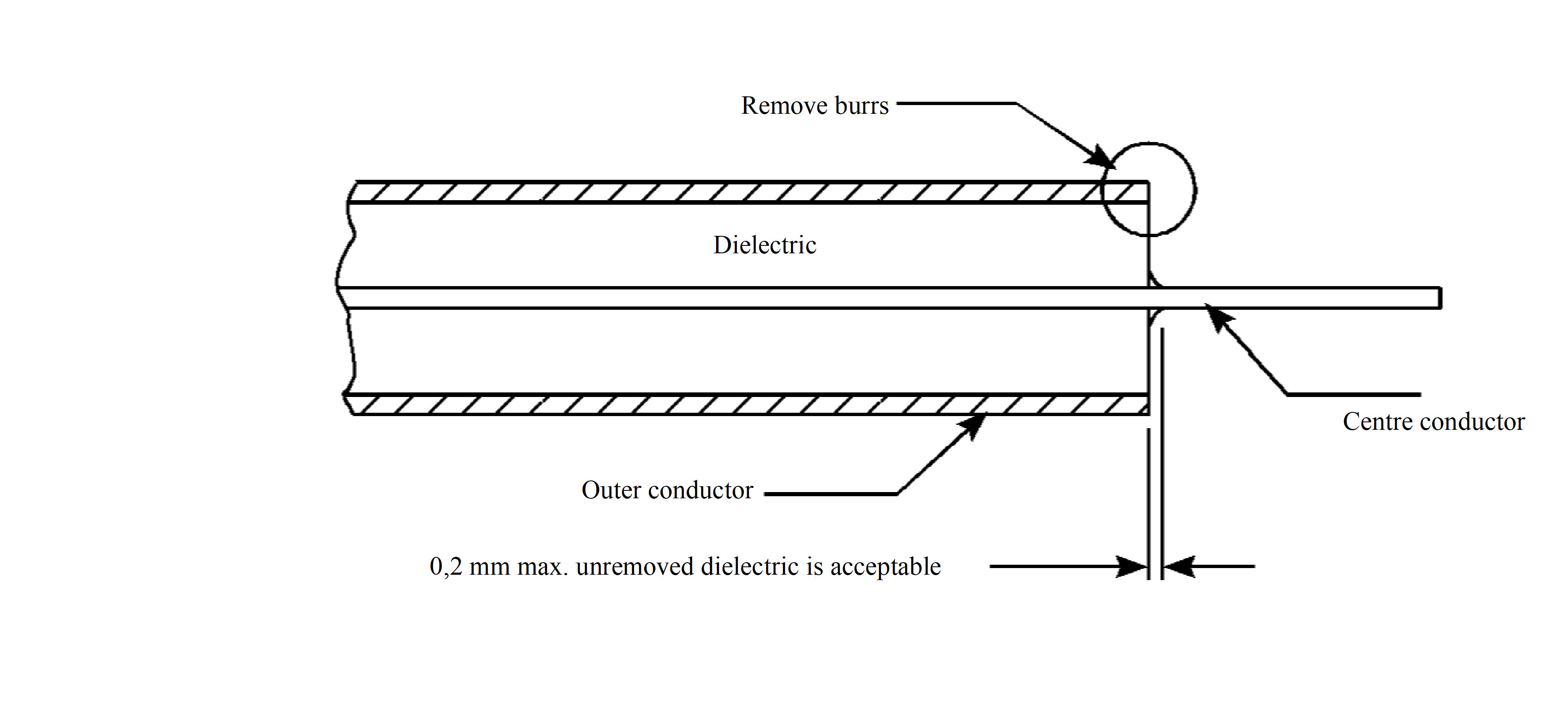 Figure 51: Dimensional inspection requirements
Preparation for soldering assembly of semirigid cables
General
The supplier shall establish written procedures which define the various process steps including as a minimum the requirements of clause 5.4.2 and 5.4.3.
Degolding and pretinning
The supplier shall remove gold from all surface areas to be joined by soldering.
The central contact pin can be degolded and pretinned with a soldering iron by melting a short length of 63 Sn or 60 Sn solder wire within the cup to dissolve gold plating; the liquid solder can then be wickedout with stranded wire.
The supplier shall degold and pretin the jointing surface of the connector body by fitting the connector to a suitable sized PTFE plug held vertically in a vice.
The supplier may melt solder wire onto the jointing area and remove it with the aid of a solder wick at least twice until the solidified pretinned surface has a shiny appearance indicating a goldfree condition.
With the rightangle type of connector, the supplier shall degold and pretin the solder mounting surfaces of the inspection and assembly cover and the corresponding surfaces of the body before assembly.
The supplier shall pretin the cable’s outer and inner conductors.
The supplier shall check for possible dielectric protrusion after the cable has cooled down to room temperature.
The supplier shall trim any protrusion with a scalpel blade.
The supplier shall check the fit of the pretinned cable in the connector.
The supplier may use activated fluxes for degolding and pretinning operations.
If activated fluxes are used, the supplier shall remove them immediately after the cable has returned to room temperature.
There shall be no dewetting of the solder on the cable conductor or on the connector.
The supplier shall clean all surfaces with an approved solvent until they are free from all residual flux and other visible contamination.
- 1 For solvents refer to clause 5.2.3.
- 2 The recommended degolding and pretinning temperatures are 250 °C to 280 °C, and 210 °C to 260 °C, respectively, when using solder immersion.
The supplier should perform pretinning just before proceeding with the assembly of the connector on the cable.
Solder preforms
The supplier shall either
use solder preforms with an internal diameter matching the outer diameter of the coaxial cable which are available as prefluxed continuous rings, or
prepare solder preforms by winding 96 Sn solder wire around mandrels having the same outer diameter as the coaxial cable (0,085 or 0,141 inches).
The supplier shall predetermine the diameter of the wire and the number of turns by trials.
This is necessary since they depend on the type of connector.
The supplier shall make as many preforms as the number of connectors to be soldered.
The supplier shall use a scalpel blade to cut solder turns in a direction perpendicular to the wire wrap.
This is shown in Figure C-4.
Before use, the supplier shall clean the preforms with one of the solvent cleaners specified in clause 5.2.3
Assembly of connectors to RF coaxial cables
Solder assembly of semirigid cables
Straight cableend connector
Centre contact assembly
The centre contact shall be slid onto the prepared centre conductor of the cable with an easy sliding fit.
The centre conductor shall be visible across the full diameter of the inspection hole.
The gap between the rear/end of the centre contact and the face of the dielectric/outer conductor shall be as specified in the assembly instructions for the type of cableend connector being used.
An example is given in Figure C-5.
The supplier shall solder the centre contact to the centre conductor with the solder specified in clause 5.2.1 and the equipment specified in clause 5.1.4.7.
After the solder has solidified and cooled, the supplier shall clean the joint with one of the solvent cleaners specified in clause 5.2.3.
After soldering, the supplier shall recheck the gap between the centre contact and the face of the dielectric/outer conductor.
The supplier shall inspect the solder connection against the following criteria:
- The inspection hole is filled with solder.
- The appearance of the solder joint satisfies the “Acceptance criteria” given in ECSS-Q-ST-70-08.
- There is no flux or other residues on the cable or the contact.
- There is no solder spillage or flow onto the mating surfaces of the contact.
- Where any solder flow or spillage has occurred on the nonmating outer surfaces of the contact, it does not cause the effective contact dimensions to exceed those specified for successful connector assembly.
Connectorbody/cable assembly
The supplier shall assemble the remaining connector parts to the cable in the following sequence:
- Slide any cable identification and other sleeves onto the cable in the sequence defined by the cable assembly or layout drawings or specifications.
- In the case of a straight cableend connector, slide the coupling nut onto the cable with the internal thread facing the end of the cable to which the connector is being assembled.
- Slide the solder preform (if used) onto the cable.
- Assemble the body of the connector to the centre contact and the end of the cable.
The assembly of the body of the connector to the centre contact and the end of the cable should be with an easy sliding fit in both cases (centre contact and pretinned outer conductor fitting).
At this stage, the supplier shall check the dimensional relationships of the connector body to the centre conductor and the correct full insertion of the cable outer conductor into the connector body.
The supplier shall solder the outer conductor of the cable to the body of the connector with the solder specified in clause 5.2.1 and the equipment specified in clause 5.1.4.7.
After the solder has solidified and cooled, the supplier shall clean the joint with one of the solvent cleaners specified in clause 5.2.3.
Inspection of assembly
After soldering and cleaning, the supplier shall inspect the assembly of the connector to the cable against the following criteria:
- The dimensional relationship of the centre contact and body of the connector is correct.
- The appearance of the outer conductor to connector body solder joint satisfies the visual “Acceptance criteria” given in ECSS-Q-ST-70-08.
- There is no solder flow or other residues on the cable or connector.
- There is no solder flow or spillage onto the mating surfaces of the connector or onto the shoulder of the connector body where it interfaces with the coupling nut.
- Any other solder flow or spillage onto the body of the connector does not affect the operation of the coupling nut.
- There is no solder spillage or other contamination on the coupling nut.
Right angle cableend connector
The supplier shall assemble the connector to the cableend in conformance with the requirements 5.5.1.2b to 5.5.1.2r.
After preconditioning as defined in clause 5.3.5, the supplier shall cut the cableend to the dimensions necessary for correct fitting to the connector as shown in Figure 52.
The supplier shall then degold and pretin the cable-end as defined in clause 5.4.2.
The supplier shall prepare the connector by degolding the bifurcated pin, the seating for the cover and the cover.
The supplier shall insert the cable into the connector and the assembly (cable and connector) and shall ensure that the angular relationship between preformed cable and connector is correct.
The supplier shall inspect the insertion of the cable into the connector via the inspection/assembly hole to ensure that it is in conformance with Figure 52.
The supplier shall make first the solder joint between the inner conductor of the cable and the bifurcated pin of the connector with the aid of a fine soldering iron and the solder defined in clause 5.2.1.
After the solder has solidified and cooled, the supplier shall clean the centreconductor solder joint and the cavity in the connector body with one of the solvent cleaners specified in clause 5.2.3.
The supplier shall inspect the solder joint to ensure that full insertion of the inner conductor of the cable into the bifurcated pin of the centre conductor of the connector has taken place.
See also Figure 52.
The supplier shall inspect the solder joint to ensure that the “Final inspection” requirements of ECSS-Q-ST-70-08 are satisfied.
The supplier shall now solder the outer conductor of the cable to the body of the connector with the aid of the solder specified in clause 5.2.1 and the equipment specified in clause 5.1.4.7.
After the solder has solidified and cooled, the supplier shall clean the joint with one of the solvent cleaners specified in clause 5.2.3.
The supplier shall inspect the solder joints between the cable and the connector to ensure that the dimensions of the cableconnector interface still conform to Figure 52
The supplier shall inspect the solder joints between the cable and the connector to ensure that the solder joints conform to the “Final inspection” requirements of ECSS-Q-ST-70-08.
The supplier shall now assemble the cover to the inspection/assembly hole and the solder joint formed with a soldering iron using the solder specified in clause 5.2.1.
The supplier shall not add extra solder during this operation.
- 1 The joint relies on reflowing of the solder applied during the degolding/pretinning operation only.
- 2 This is to prevent the flow of excess solder into the cavity in the connector body.
After the solder has solidified and cooled, the supplier shall clean the joint with one of the solvent cleaners specified in clause 5.2.3.
The supplier shall inspect the cover solder joint with respect to the following criteria: - The solder joint extends around the complete periphery of the cover.
- The cover is fully inserted into the shoulder of the hole
See Figure 52.
- The solder joint conforms to the “Final inspection” requirements of ECSS-Q-ST-70-08.
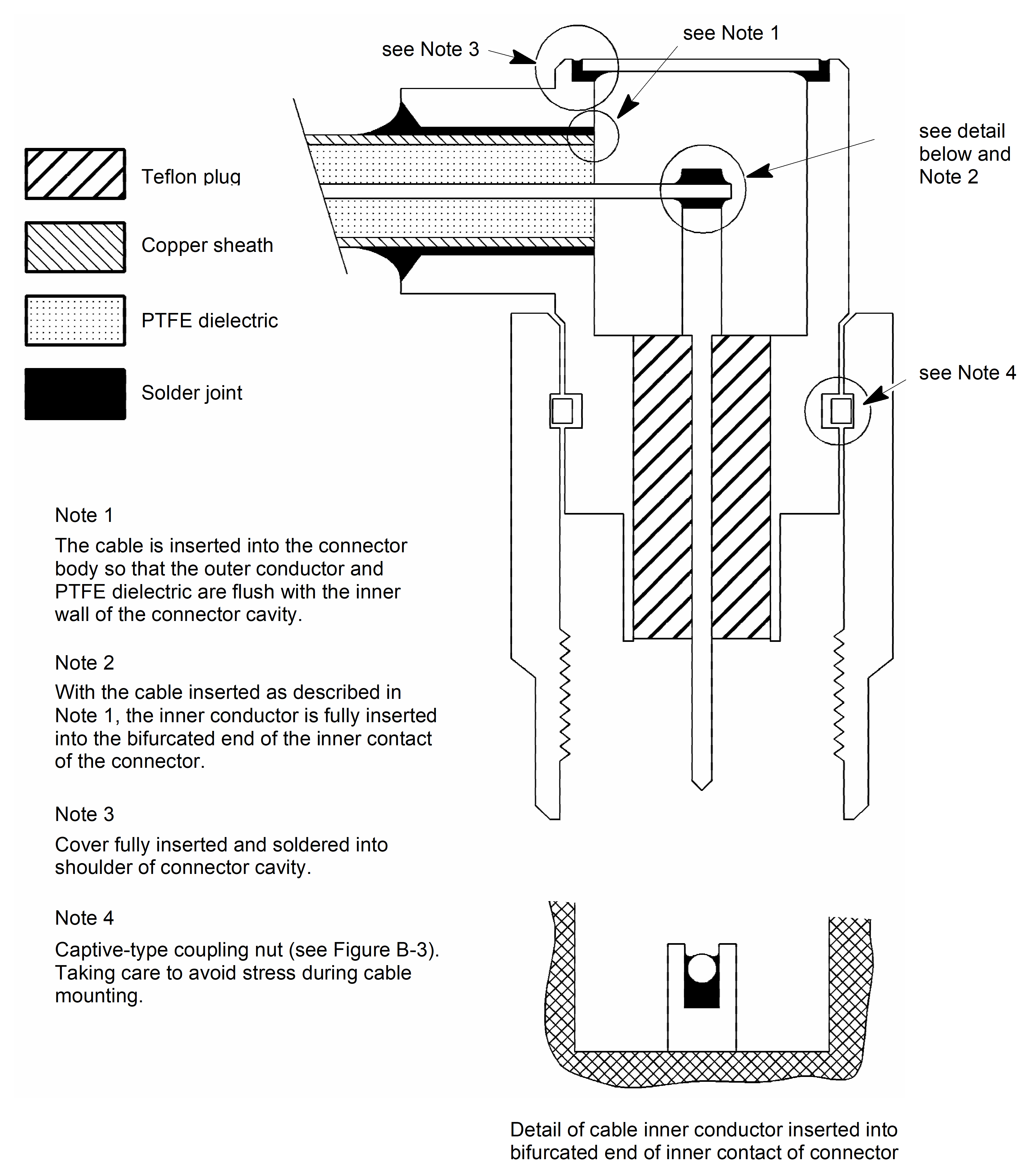 Figure 52: Right angle cable-end connector assembly
Crimp assembly of semirigid cables and other assembly techniques
The supplier shall assemble the connectors and cables in conformance with formally documented and qualified procedures.
The supplier shall submit these procedures for customer acceptance.
This acceptance can involve a customer audit of the facilities and procedures used for assembling the cables and connectors.
As final stage of assembly, the supplier shall perform an inspection covering dimensional conformance, cleanliness, lack of damage and quality of the assembly techniques used.
Completed assemblies
When the assembly of the cable and connectors is complete, the supplier shall inspect it to ensure that it is dimensionally correct and clean.
- 1 “Dimensionally correct” means in accordance with the layout drawing or jig.
- 2 “Clean” means for example free from contaminants, particles and burrs.
The completed and inspected cable assembly shall have protective caps fitted over the connectors.
Where for thermal or other reasons the cable assembly is painted, the paint shall be applied to the outer conductor of the cable only and shall stop at least 5 mm before the joint to the connector (e.g. solder fillet and crimp ferrule).
Connectors are not painted.
The paint used shall conform to the “Acceptance limits” requirements of ECSS-Q-ST-70-02.
The supplier shall store the cable in a suitable container inside a sealed bag with an inert atmosphere.
The storage packaging shall be adequate to protect the cable against deformation, damage and contamination.
The supplier shall provide a suitable shipping container to give the necessary additional protection to the storage packaging for delivery purposes.
Mounting of cables
Semirigid cables with straight soldertype connectors
The supplier shall remove the assembled cable from its storage packaging only when it is needed for immediate mounting.
After removal from the storage packaging, the supplier shall inspect the cable assembly before mounting.
The supplier shall ensure that the mating surfaces and screw threads are clean and free from damage.
The supplier shall retract the connector coupling nuts along the cable until they are at least 1 cm clear of the connector body.
The connector inner contacts shall be inserted into the receptacles in the mating halves and slid home so that the mating faces of the bodies of the mating connectors are in contact.
During this operation, the supplier shall apply no lateral force to correct misalignment of the cableend connectors and the mating connectors.
Longitudinal force shall only be applied in the case where the connectors mating with the cable are facing each other
In the case specified in 5.6.1g, the following shall apply:
- limit the force to that required to compress the cable temporarily by the length of one connector inner contact mating face.
- ensure that the cable has generous stress relief bends
This allows the temporary compression to be, in fact, a minor bending.
At the completion of the connector mating operation, the cable shall be lying without external force, both cableend connectors having the inner contacts fully inserted and the cable lying in contact with all support points.
The supplier shall now loosely screw the two connector coupling nuts onto the mating connector bodies and tighten to the specified torque, but in the range 0,8 Nm to 1,1 Nm.
During the nut mating and torquing operations, the supplier shall ensure that no rotation of the cableend connector body or of the cable takes place.
The supplier shall now secure the cable to its support points (where applicable).
The supplier shall reject any cable that cannot be installed in conformance with the procedure described in the requirements 5.6.1a to 5.6.1l and shall provide a new cable to the correct dimensions.
Semirigid cables with rightangle connectors
The supplier shall unpack and inspect the cable as defined in requirements 5.6.1a to 5.6.1c..
The supplier shall align the cableend connectors with their mating connectors simultaneously and the centre contacts with their mating receptacles.
During this operation, the supplier shall apply no lateral force to correct misalignment of the cableend connectors and the mating connectors.
The supplier shall screw the connector coupling nuts onto the mating connector bodies until fingertight and shall then unscrew it 1/4 turn.
In this condition the cable is resting in contact with its support points (where applicable), but is free to move within the constraint given by the 1/4 turn loosening of the connectors.
The supplier shall now finger-tighten and torque the connectors to the specified figure for the particular connector, but in the range 0,8 Nm to 1,1 Nm).
During the nut mating and torquing operations, the supplier shall ensure that no rotation of the cableend connector body or of the cable takes place.
Other cable mounting technologies
The mounting requirements for other technologies should be defined by the suppliers of the connectors, cables or assemblies.
The supplier shall use everywhere stressfree mounting of assembled cables to the interfacing connectors .
For each technology, the supplier shall respect the bendradius constraints for the particular type of cable.
The supplier shall respect the cablesupport requirements for the particular type of cable.
Particularly in the case of flexible cables having an expanded type of dielectric, the cable clamps should be of a carefully designed rigid type that enables any forces resulting from vibration to be distributed over a significant length of the cable.
- 2 This is done to avoid local dielectric crushing and, hence, degradation of electrical performance.
Process verification
General
The supplier shall conduct verification tests to establish confidence in the reliability of solderjoint configurations and processing methods not shown in this Standard.
The configuration shall be considered verified if no cracked solder joints or part damage is found after 200 thermal cycles in accordance with the test conditions given in clause 5.7.2 and vibration given in clause 5.7.3 and when the configuration is examined under 15× minimum magnification.
The supplier shall ascertain the absence of cracks within the interconnection by metallography, microsections being made in the longitudinal midplane of the assembly.
Temperature cycling
The supplier shall perform the temperature cycling in conformance with the requirements given in clause 13.3 of ECSS-Q-ST-70-08.
These conditions can be modified by the customer to conform with the particular environmental qualification conditions for the assembly being verified.
Vibration
After completion of the temperature cycling, the supplier shall subject the test specimen to vibration.
The supplier shall derive the test levels, frequencies and durations from the system requirements.
The severity of the vibration tests shall not be inferior to that shown in the following tables of ECSS-Q-ST-70-08:
- Sine survey
- Minimum severity for sine vibration testing
- Minimum severity for random vibration testing for all applications except launchers
- Minimum severity for random vibration testing for launchers.
Quality assurance
Data
The supplier shall retain the quality records for at least ten years, or in accordance with project business agreement requirements.
Example of quality records are logbooks.
The content of the quality records shall be in conformance with the DRD in Annex A.
Nonconformance
The supplier shall disposition any nonconformance observed in respect of the soldering process in conformance with quality assurance requirements in ECSS-Q-ST-10-09.
If a repair procedure is agreed, the supplier shall perform it in conformance with ECSS-Q-ST-70-28.
Calibration
The supplier shall calibrate any measuring equipment to traceable reference standards.
The supplier shall record any suspected or actual equipment failure as a project nonconformance report according to ECSS-Q-ST-20.
This is to ensure that previous results can be examined to ascertain whether or not reinspection or retesting is required.
The supplier shall notify the final customer of the nonconformance details.
Traceability
The supplier shall maintain traceability throughout the process from incoming inspection to final test, including details of test equipment and personnel employed in performing the task.
Workmanship standards
The supplier shall prepare visual standards consisting of work samples or visual aids that illustrate the quality characteristics of all soldered connections involved.
The supplier shall make the visual standards specified in 5.8.5a, available to each operator and inspector.
The supplier shall include the illustrations presented in Annex B of this Standard, supplemented as necessary, as examples.
Inspection
During all stages of the process, the inspection points shall be observed.
Operator and inspector training and certification
The supplier shall employ trained and competent personnel for all soldering and crimping operations and inspections.
The supplier shall develop, maintain and implement a training programme to provide for excellence of workmanship and personnel skills and a thorough knowledge of the requirements detailed in this Standard.
The supplier shall obtain certificates for trained personnel performing soldering and crimping operations and inspections.
This certification shall be based upon objective evidence of quality, resulting from test and inspection of completed joints.
The supplier shall apply retraining or reassessment of personnel in cases of repetitive unacceptable quality levels and changes in soldering or assembly techniques, parameters or required skills.
The supplier shall maintain records of the training and certification status of operators and inspection personnel.
All training shall be performed at a school authorized by the final customer.
ANNEX(normative)Logbook – DRD
DRD identification
Requirement identification and source document
This DRD is called from ECSS-Q-ST-70-18, requirement 5.8.1b.
Purpose and objective
The purpose of the logbook is to summarize the quality records.
Expected response
Scope and content
The logbook shall contain a copy of the final inspection documentation.
The logbook shall refer to the non-conformance report and corrective actions.
The logbook shall contain a copy of the inspection and test results with reference to the procedure, drawings, personnel, tools, solders, fluxes and solvents utilized.
The logbook shall contain measurements of the external length of the centre conductor.
The logbook shall contain records of the training and certification status of operators and inspection personnel.
The logbook shall contain the finding and related corrective action raised during the audit.
Special remarks
None.
ANNEX(normative)Workmanship standards
Overview
Requirement 5.8.5c requires the inclusion of the illustrations presented in B.2 in the visual standards prepared by the supplier.
Illustrations
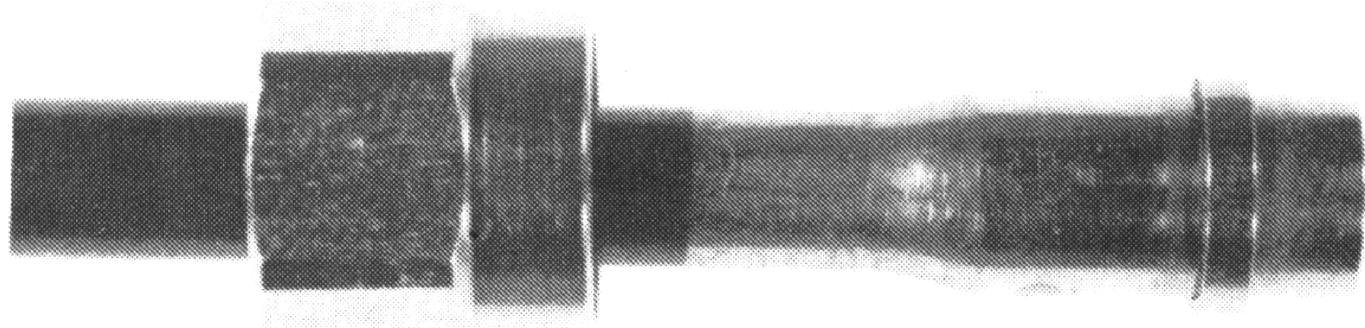 Figure: Photograph showing noncaptive nut and preferred solder fillet
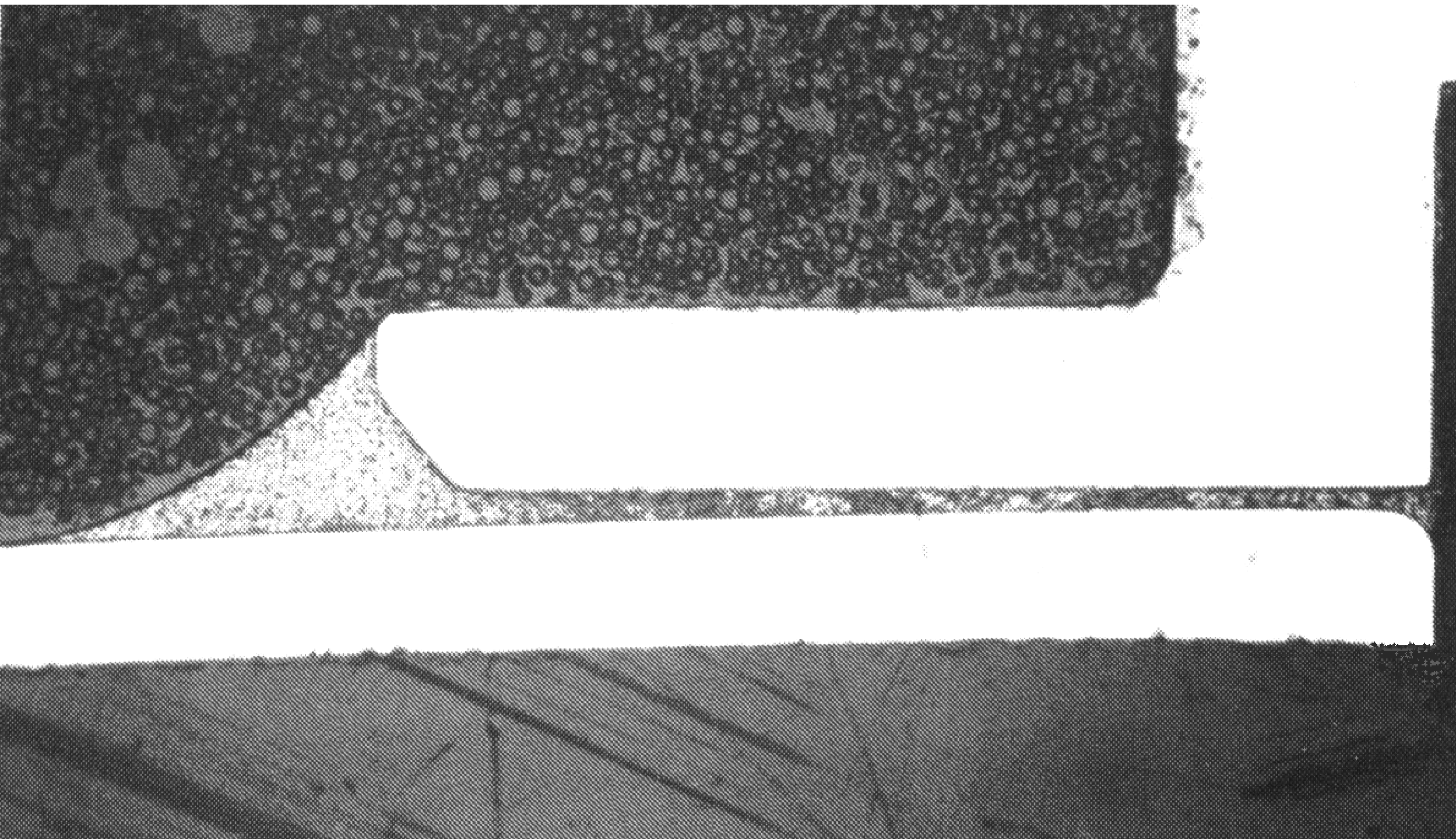 Figure: Microsection through preferred solder fillet, revealing full penetration of solder path
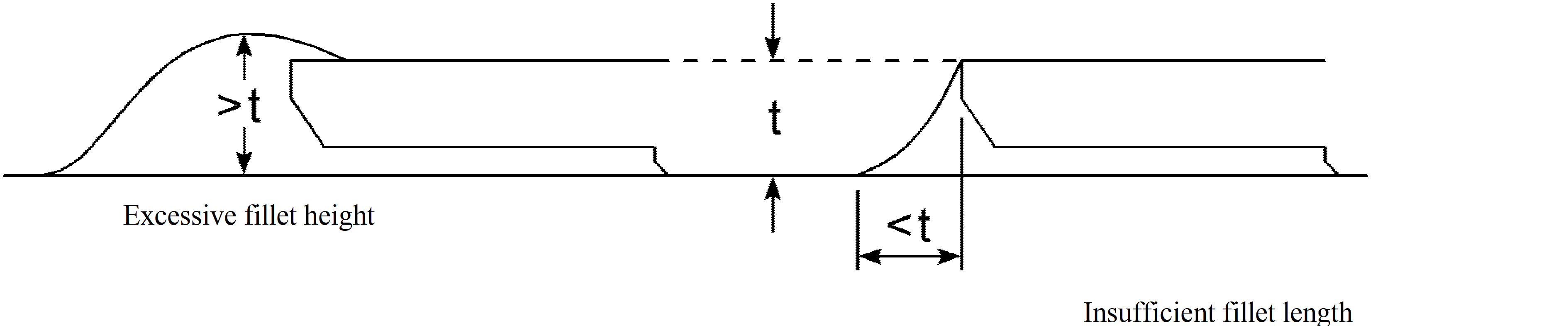 Figure: Unacceptable solder fillet dimensions
ANNEX(informative)Graphical information
Overview
A graphical representation of the typical dimensional inspection requirements can be found in Figure 51.
A view of the Right angle cable-end connector assembly is shown in Figure 52.
Clauses C.2 to C.6 show additional useful graphical information.
Typical cable cutoff fixture
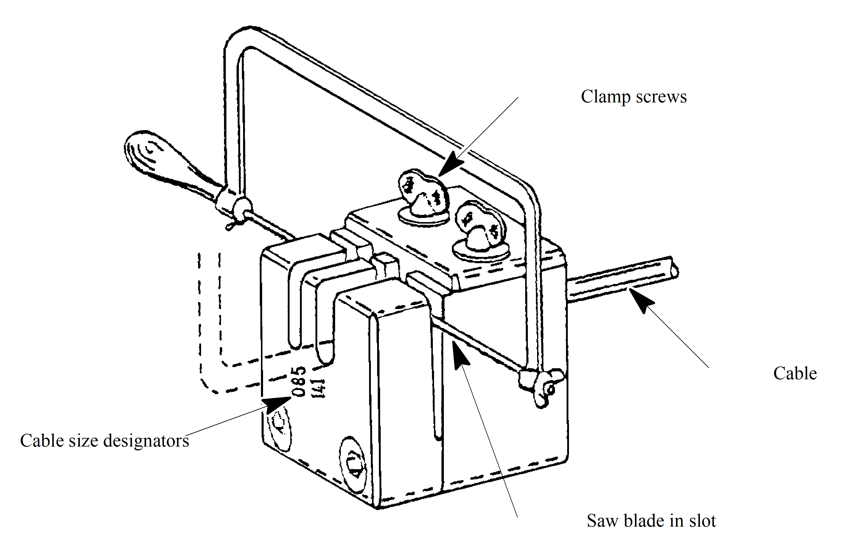 Figure: Typical cable cutoff fixture
Typical cableforming tool
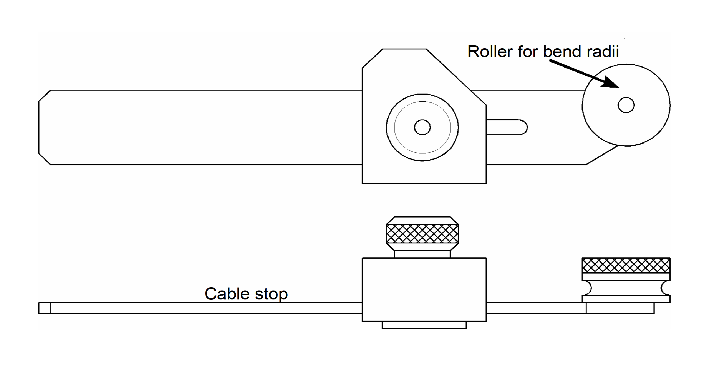 Figure: Typical cableforming tool
Approved and nonapproved straight soldertype cableend connectors
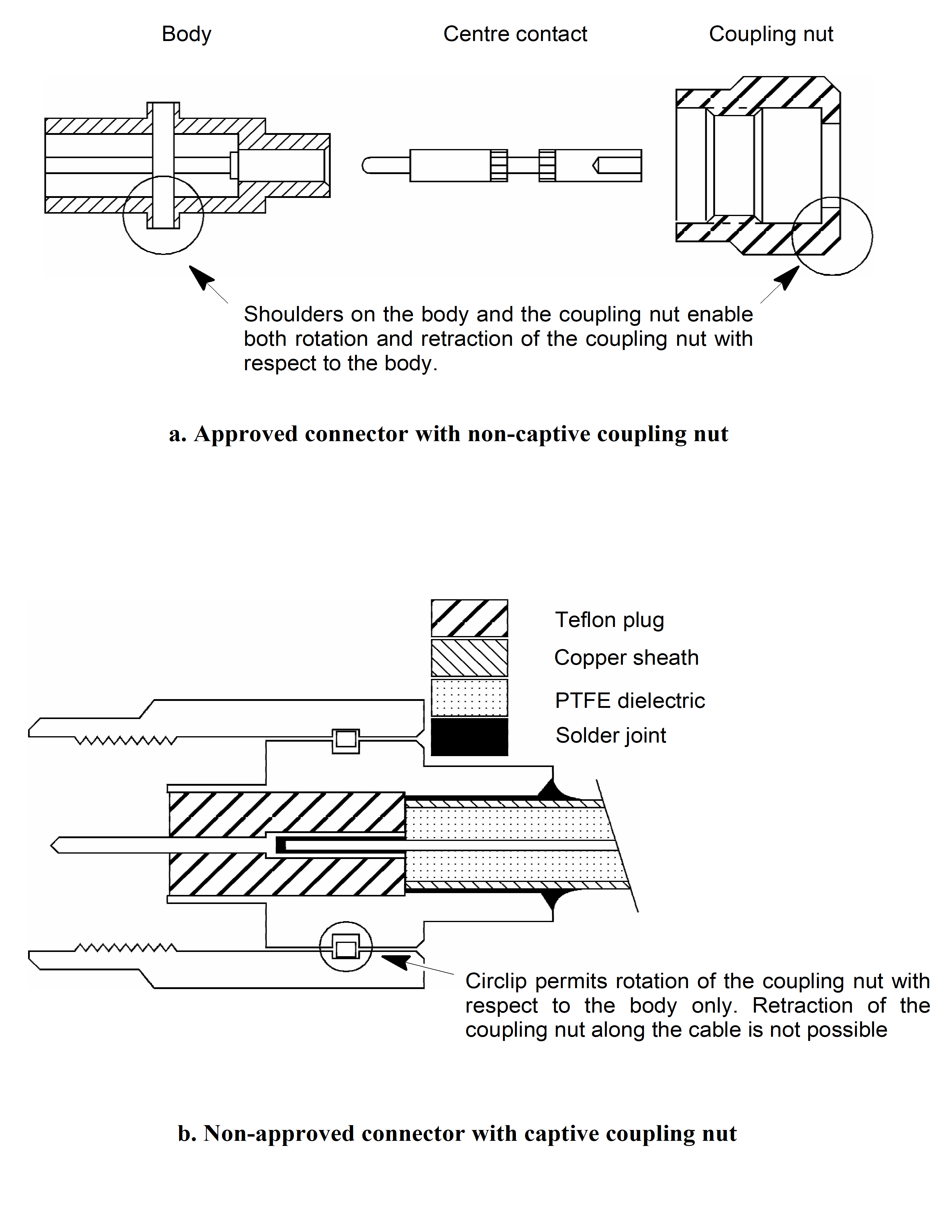 Figure: Approved and nonapproved straight soldertype cableend connectors
Method of producing solder performs
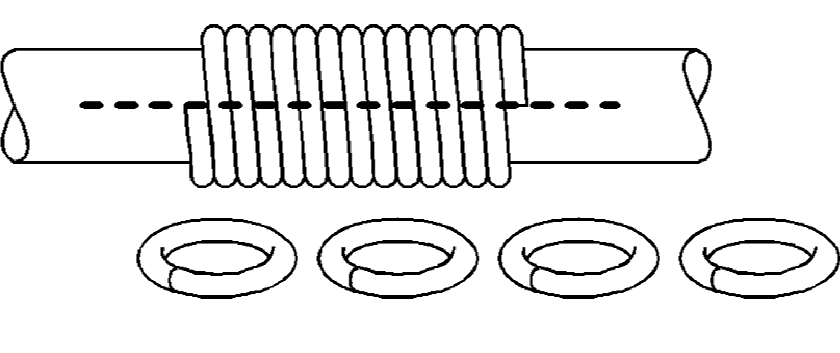 Figure: Method of producing solder preforms
Centre contact assembly
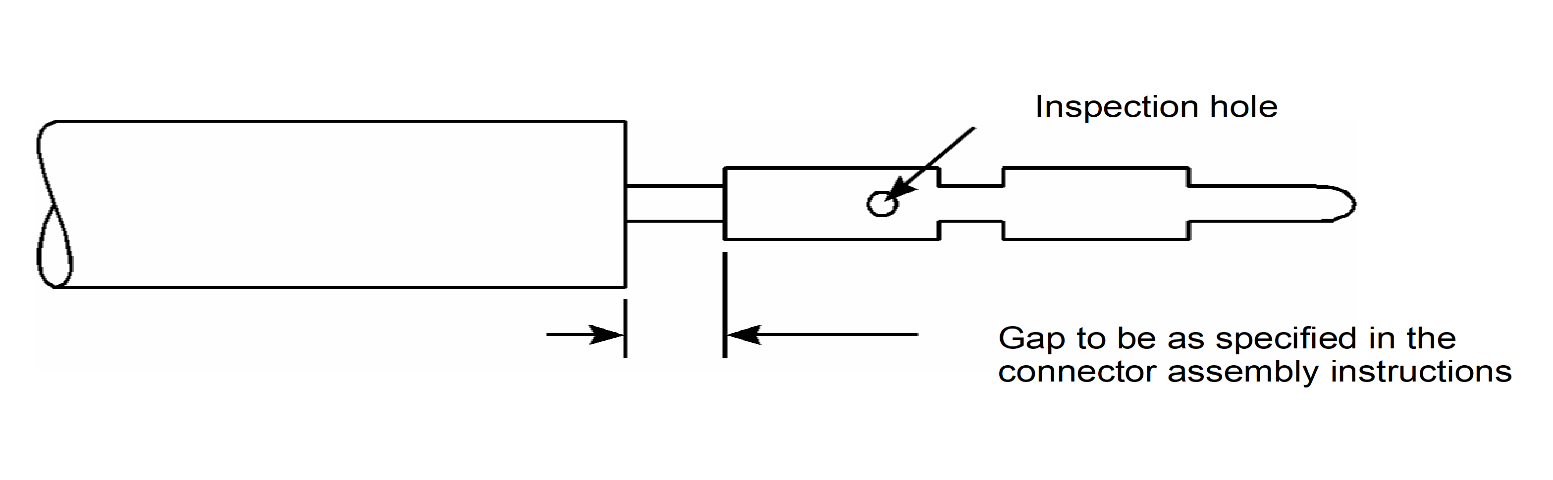 Figure: Centre contact assembly
Bibliography
|
ECSS-S-ST-00
|
ECSS system – Description, implementation and general requirements
|
|
ECSS-Q-ST-70
|
Space product assurance — Materials, mechanical parts and processes
|
|
ECSS-Q-ST-70-71
|
Space product assurance — Data for selection of space materials
|