
Space product assurance
Commercial electrical, electronic and electromechanical (EEE) components
Foreword
This Standard is one of the series of ECSS Standards intended to be applied together for the management, engineering and product assurance in space projects and applications. ECSS is a cooperative effort of the European Space Agency, national space agencies and European industry associations for the purpose of developing and maintaining common standards. Requirements in this Standard are defined in terms of what shall be accomplished, rather than in terms of how to organize and perform the necessary work. This allows existing organizational structures and methods to be applied where they are effective, and for the structures and methods to evolve as necessary without rewriting the standards.
This Standard has been prepared by the ECSS-Q-ST-60-13C Working Group, under the auspice of the ESCC Space Components Steering Board, reviewed by the ECSS Executive Secretariat and jointly approved by the ESCC SCSB and the ECSS Technical Authority.
Disclaimer
ECSS does not provide any warranty whatsoever, whether expressed, implied, or statutory, including, but not limited to, any warranty of merchantability or fitness for a particular purpose or any warranty that the contents of the item are error-free. In no respect shall ECSS incur any liability for any damages, including, but not limited to, direct, indirect, special, or consequential damages arising out of, resulting from, or in any way connected to the use of this Standard, whether or not based upon warranty, business agreement, tort, or otherwise; whether or not injury was sustained by persons or property or otherwise; and whether or not loss was sustained from, or arose out of, the results of, the item, or any services that may be provided by ECSS.
Published by: ESA Requirements and Standards Division ESTEC, P.O. Box 299, 2200 AG Noordwijk The NetherlandsCopyright: 2013© by the European Space Agency for the members of ECSS## Change log
|
ECSS-Q-ST-60-13C
|
First issue.
|
Introduction
This standard is based on and complementary to ECSS-Q-ST- (with upward revisions). This standard can only be used in conjunction with ECSS-Q-ST- in its current revision. This standard applies only to commercial components - as defined in its scope - which meet defined technical parameters that are on the system application level demonstrated to be unachievable with existing space components or only achievable with qualitative and quantitative penalties. The standard requires that qualitative and quantitative penalties are specified, as applicable, as a minimum in terms of quantifiable parameters such as: functional capability, parts count, power dissipation, frequency of operation, data/signal processing efficiency, interconnect complexity, mass, volume, …
For traceability to ECSS-Q-ST-60, the modifications or additions are marked in blue. Text in black colour is unmodified text.
The objective of the EEE component selection, control, procurement and use requirements is to ensure that EEE components used in a space project enables the project to meet its mission requirements.
Important elements of EEE component requirements include:
component programme management,
component selection, evaluation and approval,
procurement,
handling and storage,
component quality assurance,
specific components, and
documentation.
The main tools which can be used to reach the objective are:
concurrent engineering,
standardization of component types,
characterization of components,
assessment of component manufacturers including declared competencies and processes,
testing, screening, lot acceptance and periodic testing,
procurement specifications,
control and inspection,
control of nonconforming materials,
assessment and use of existing component data,
application of specific control to mitigate risk for components with limited data or confidence, and
information management.
The basic approach is as follows:
The customer of a given space project defines the EEE component requirements within the boundaries of this standard. They appear in the appropriate clauses of the project requirements as defined in ECSS-M-ST-10.
The supplier defines a component control plan to implement those requirements into a system which enables, for instance, to control the selection, approval, procurement, handling in a schedule compatible with his requirements, and in a cost-efficient way.
The supplier ensures that the applicable parts requirements are passed down to lower level suppliers and ensure that they are compliant to these parts requirements.
Scope
This standard defines the requirements for selection, control, procurement and usage of EEE commercial components for space projects.
This standard is applicable to commercial encapsulated active monolithic parts (integrated circuits and discrete):
diodes
microwave diodes
integrated circuits
microwave integrated circuits (MMIC)
transistors
microwave transistors
This standard is not applicable to the commercial parts from the following families:
capacitors
connectors
crystals
filters
fuses
heaters
inductors
microwave passive parts
oscillators
relays
resistors
switches
thermistors
transformers
cables & wires
hybrids
surface acoustic waves (SAW)
charge coupled devices (CCD)
active pixel sensors (APS)
In addition, the following families of EEE components are not addressed by the present ECSS standard but it can be used as guideline and revisited on case/case basis:
photodiodes
light emitting diodes (LED)
phototransistors
opto-couplers
laser diodes
In line with ECSS-Q-ST-60, this standard differentiates between three classes of components through three different sets of standardization requirements (clauses) to be met.
The three classes provide for three levels of trade-off between assurance and risk. The highest assurance and lowest risk is provided by class 1 and the lowest assurance and highest risk by class 3. Procurement costs are typically highest for class 1 and lowest for class 3. Mitigation and other engineering measures can decrease the total cost of ownership differences between the three classes. The project objectives, definition and constraints determine which class or classes of components are appropriate to be utilised within the system and subsystems.
Class 1 components are described in Clause 4
Class 2 components are described in Clause 5
Class 3 components are described in Clause 6
Annex G includes a diagram that summarizes the difference between these three classes for evaluation, screening and lot acceptance.
The requirements of this document are applicable to all parties involved at all levels in the integration of EEE commercial components into space segment hardware and launchers.
For easy tailoring and implementation of the requirements into a Requirement Management Tool, and for direct traceability to ECSS-Q-ST-60, requirements in this standards have been written in the way of a ECSS Applicability Requirement Matrix (EARM), as defined in Annex A of ECSS-S-ST-00 “ECSS system – Description, implementation and general requirements”.
This standard may be tailored for the specific characteristics and constrains of a space project in conformance with ECSS-S-ST-00.
Normative references
The following normative documents contain provisions which, through reference in this text, constitute provisions of this ECSS standard. For dated references, subsequent amendments to, or revision of any of these publications do not apply. However, parties to agreements based on this ECSS Standard are encouraged to investigate the possibility of applying the more recent editions of the normative documents indicated below. For undated references, the latest edition of the publication referred to applies.
|
ECSS-S-ST-00-01
|
ECSS system - Glossary of terms
|
|
ECSS-Q-ST-60
|
Space product assurance - Electrical, electronic and electromechanical (EEE) components
|
|
ECSS-Q-ST-60-14
|
Space product assurance - Relifing procedure - EEE components
|
|
ECSS-Q-ST-60-15
|
Space product assurance – Radiation hardness assurance – EEE components
|
|
ESCC 21300
|
Terms, definitions, abbreviations, symbols and units
|
|
ESCC 24900
|
Minimum requirements for controlling environmental contamination of components
|
|
ESCC 25500
|
Methodology for the detection of pure tin in the external surface finish of case and leads of EEE components
|
|
MIL-STD-750
|
Test methods for semiconductor devices
|
|
MIL-STD-883
|
Test method standard microcircuits
|
|
JESD22-A101
|
Steady state temperature humidity bias life test
|
|
JESD22-A110
|
Highly accelerated temperature and humidity stress test
|
|
JESD22-A113
|
Preconditioning of plastic surface mount devices prior to reliability testing
|
|
JESD22-A121
|
Test Method for Measuring Whisker Growth on Tin and Tin Alloy Surface Finishes
|
|
JESD22-B106
|
Resistance to soldering temperature for through hole mounted devices
|
|
JESD-201
|
Environmental Acceptance Requirements for Tin Whisker Susceptibility of Tin and Tin Alloy Surface Finishes
|
|
J-STD-020
|
Moisture/Reflow sensitivity classification for nonhermetic solid state surface mount devices
|
|
J-STD-033
|
Handling, packing, shipping and use of moisture/ reflow sensitive surface mount devices
|
Terms, definitions and abbreviated terms
Terms from other standards
For the purpose of this standard, the terms and definitions from ECSS-S-ST-00-01 apply.
For the purpose of this standard, the following terms and definitions from ECSS-Q-ST-60 apply:
agent
characterization
commercial component
concurrent engineering
franchised distributor
parts engineer
parts procurer
qualified parts
screening
space qualified parts
Terms specific to the present standard
traceability information (trace code)
unique identifier used by manufacturers to label and trace a quantity of components with a common manufacturing history and thereby common characteristics.
- 1 The notion of "lot of EEE parts" used for the radiation and lot acceptance tests is defined by the trace code.
- 2 Several trace codes can be part of a same delivery from the manufacturer or the distributor.
- 3 It is possible to have several diffusion lots (as per ESCC 21300) in the same trace code.
Abbreviated terms
For the purpose of this Standard, the abbreviated terms from ECSS-S-ST-00-01 and the following apply:
|
Abbreviation
|
Meaning
|
|
AOQ
|
average outgoing quality
|
|
ASIC
|
application specific integrated circuit
|
|
BGA
|
ball grid array
|
|
CA
|
construction analysis
|
|
CCD
|
charge coupled device
|
|
CCP
|
component control plan
|
|
CN
|
change notice
|
|
CoC
|
certificate of conformance
|
|
CDR
|
critical design review
|
|
CR
|
change request
|
|
DCL
|
declared components list
|
|
DPA
|
destructive physical analysis
|
|
DRD
|
document requirement definition
|
|
DSM
|
deep Sub-Micron
|
|
Ea
|
activation energy
|
|
ECSS
|
European Coordination for Space Standardization
|
|
EEE
|
electrical, electronic, electromechanical
|
|
EFR
|
early failure rate
|
|
ESCC
|
European space components coordination
|
|
GSE
|
ground support equipment
|
|
HAST
|
highly accelerated stress test
|
|
HTRB
|
high temperature reverse bias
|
|
JD
|
justification document
|
|
LAT
|
lot acceptance test
|
|
LED
|
light emitting diode
|
|
LVT
|
lot validation testing
|
|
MMIC
|
microwave monolithic integrated circuit
|
|
PAD
|
parts approval document
|
|
PCB
|
parts control board
|
|
PCN
|
process change notice
|
|
PDA
|
percent defective allowable
|
|
PED
|
plastic encapsulated device
|
|
PIND
|
particle impact noise detection
|
|
QBSD
|
full quadrant back scatter electron detector
|
|
QCI
|
quality conformance inspection
|
|
RFD
|
request for deviation
|
|
RH
|
relative humidity
|
|
RoHs
|
restriction of the use of certain hazardous substances
|
|
RVT
|
radiation verification testing
|
|
SCSB
|
Space Components Steering Board
|
|
SAM
|
scanning accoustic microscopy
|
|
SEM
|
scanning electron microscope
|
|
SMD
|
surface mount device
|
|
TCI
|
technology conformance inspection
|
|
Tg
|
glassivation temperature
|
|
THB
|
temperature humidity bias
|
|
Tj
|
junction temperature
|
|
T/C
|
thermal cycling
|
Conventions
The term “EEE component“ is synonymous with the terms "EEE Part", "Component" or just "Part".
The term “for approval” means that a decision of the approval authority is necessary for continuing the process.
The term “for review” means that raised reviewers comments are considered and dispositioned.
The term “for information” means that no comments are expected about the delivered item.
For the purpose of clear understanding of this document, hereunder is a listing of component categories which are covered by the term EEE component, encapsulated or non-encapsulated, irrespective of the quality level:
Capacitors
Connectors
Crystals
Discrete semiconductors (including diodes, transistors)
Filters
Fuses
Magnetic components (e.g. inductors, transformers, including in-house products)
Monolithic Microcircuits (including MMICs)
Hybrid circuits
Relays
Resistors, heaters
Surface acoustic wave devices
Switches (including mechanical, thermal)
Thermistors
Wires and Cables
Optoelectronic Devices (including optocouplers, LED, CCDs, displays, sensors)
Passive Microwave Devices (including, for instance, mixers, couplers, isolators and switches)
NOTE: NOTE Microwave switches consisting of multiple EEE components are considered as equipment. The requirements of this standard are applicable to the EEE parts they incorporate and to microwave switches having a simple design (single EEE part).
Nomenclature
The following nomenclature applies throughout this document:
The word “shall” is used in this Standard to express requirements. All the requirements are expressed with the word “shall”.
The word “should” is used in this Standard to express recommendations. All the recommendations are expressed with the word “should”.
NOTE: NOTE It is expected that, during tailoring, recommendations in this document are either converted into requirements or tailored out. The words “may” and “need not” are used in this Standard to express positive and negative permissions, respectively. All the positive permissions are expressed with the word “may”. All the negative permissions are expressed with the words “need not”.
The word “can” is used in this Standard to express capabilities or possibilities, and therefore, if not accompanied by one of the previous words, it implies descriptive text.
NOTE: NOTE In ECSS “may” and “can” have completely different meanings: “may” is normative (permission), and “can” is descriptive. The present and past tenses are used in this Standard to express statements of fact, and therefore they imply descriptive text.
Requirements for class 1 components
|
Identifier
|
Requirement
|
Applicability
| |
|
4.1 Component programme management |
|||
|
4.1.1 General |
|||
|
4.1.1a
|
|
Applicable
| |
|
4.1.2 Components control programme |
|||
|
4.1.2.1 Organization |
|||
|
4.1.2.1a
|
|
Applicable
| |
|
4.1.2.1b
|
|
Applicable
| |
|
4.1.2.2 Component control plan |
|||
|
4.1.2.2a
|
|
Applicable
| |
|
4.1.2.2b
|
|
Applicable
| |
|
4.1.2.2c
|
|
Applicable
| |
|
4.1.3 Parts control board |
|||
|
4.1.3a
|
|
Applicable
| |
|
4.1.3b
|
|
Applicable
| |
|
4.1.3c
|
|
Applicable
| |
|
4.1.3d
|
|
Applicable
| |
|
4.1.4 Declared component list |
|||
|
4.1.4a
|
|
Applicable
| |
|
4.1.4b
|
|
Applicable
| |
|
4.1.4c
|
|
Applicable
| |
|
4.1.4d
|
After equipment CDR, all modifications affecting the JD information shall be implemented, in the "as design" DCL, through the CN / CR process and submitted to the customer for approval.
|
Modified
| |
|
4.1.4e
|
|
Applicable
| |
|
4.1.4f
|
|
Applicable
| |
|
4.1.4g
|
|
Applicable
| |
|
4.1.4h
|
|
Applicable
| |
|
4.1.5 Electrical and mechanical GSE |
|||
|
4.1.5a
|
|
Applicable
| |
|
4.1.5b
|
|
Applicable
| |
|
4.2 Component selection, evaluation and approval
| |||
|
4.2.1 General |
|||
|
4.2.1a
|
|
Applicable
| |
|
4.2.1b
|
|
Applicable
| |
|
4.2.2 Manufacturer and component selection |
|||
|
4.2.2.1 General rules |
|||
|
4.2.2.1a
|
|
Applicable
| |
|
4.2.2.1b
|
|
Applicable
| |
|
4.2.2.1c
|
|
Applicable
| |
|
4.2.2.1d
|
|
Applicable
| |
|
4.2.2.1e
|
|
Applicable
| |
|
4.2.2.1f
|
|
Applicable
| |
|
4.2.2.1g
|
For the assessment of commercial components, the supplier shall collect the available data on the manufacturer and the component in the JD specified in the requirement 4.2.4d.
|
New
| |
|
4.2.2.1h
|
For Deep Sub-Micron Technologies (<90nm), the detailed test definition shall identify the technology through the construction analysis and the application.
|
New
| |
|
4.2.2.2 Parts and material restriction |
|||
|
4.2.2.2a
|
|
Applicable
| |
|
4.2.2.2b
|
|
Applicable
| |
|
4.2.2.2c
|
|
Applicable
| |
|
4.2.2.2d
|
For limited life duration, known instability, safety hazards or reliability risk reasons, EEE components listed below shall not be used:
|
Modified
| |
|
4.2.2.2e
|
|
Applicable
| |
|
4.2.2.2f
|
|
Applicable
| |
|
4.2.2.2g
|
|
Applicable
| |
|
4.2.2.2h
|
The use of pure tin (inside or outside the part) shall be declared in the JD.
|
Modified
| |
|
4.2.2.2i
|
To assess Pb free with tin finish whisker risk, the following actions shall be performed by the supplier:
|
New
| |
|
4.2.2.3 Preferred sources |
|||
|
4.2.2.3a
|
|
Not applicable
| |
|
4.2.2.3b
|
|
Not applicable
| |
|
4.2.2.3c
|
|
Applicable
| |
|
4.2.2.4 Radiation hardness |
|||
|
4.2.2.4a
|
|
Applicable
| |
|
4.2.2.4b
|
|
Applicable
| |
|
4.2.2.4c
|
|
Applicable
| |
|
4.2.2.4d
|
|
Applicable
| |
|
4.2.2.4e
|
|
Applicable
| |
|
4.2.2.4f
|
|
Applicable
| |
|
4.2.2.4g
|
|
Applicable
| |
|
4.2.2.4h
|
|
Applicable
| |
|
4.2.2.4i
|
|
Applicable
| |
|
4.2.2.5 Derating
| |||
|
4.2.2.5a
|
|
Applicable
| |
|
4.2.2.5b
|
|
Applicable
| |
|
4.2.2.6 Temperature range
| |||
|
4.2.2.6a
|
Commercial parts shall be selected in the highest available temperature range.
|
New
| |
|
4.2.2.6b
|
A minimum 10 °C margin shall be used between the maximum manufacturer temperature range and the application temperature range (including worst cases).
|
New
| |
|
4.2.2.6c
|
In case |(manufacturer max temperature range – used max temp)| < 10 °C, an electrical characterisation shall be performed at used temperature with an additional margin of 10 °C during the evaluation step.
|
New
| |
|
4.2.3 Component evaluation
| |||
|
4.2.3.1 General
| |||
|
4.2.3.1a
|
|
Applicable
| |
|
4.2.3.1b
|
|
Applicable
| |
|
4.2.3.1c
|
|
Applicable
| |
|
4.2.3.1d
|
|
Applicable
| |
|
4.2.3.1e
|
|
Applicable
| |
|
4.2.3.1f
|
|
Applicable
| |
|
4.2.3.1g
|
|
Applicable
| |
|
4.2.3.1h
|
|
Applicable
| |
|
4.2.3.1i
|
The supplier shall review the evaluation results to determine their impact on the content of the screening and lot acceptance tests.
|
Modified
| |
|
4.2.3.1j
|
|
Applicable
| |
|
4.2.3.1k
|
The supplier shall prepare a preliminary internal supplier’s specification for electrical testing during evaluation tests.
|
New
| |
|
4.2.3.1l
|
The supplier specification specified in 4.2.3.1k shall as minimum include tested parameters, test conditions, acceptance criteria, drift limits.
|
New
| |
|
4.2.3.1m
|
The supplier shall update the internal supplier’s specification used for screening and lot acceptance in accordance with the results of evaluation testing.
|
New
| |
|
4.2.3.1n
|
The preliminary and the final internal supplier’s specification as specificed in Annex C shall be submitted to the customer for approval.
|
New
| |
|
4.2.3.2 Component manufacturer assessment
| |||
|
4.2.3.2.1
|
|
Not applicable
See 4.2.2.1.g |
|
|
4.2.3.2.2a
|
|
Not applicable
See 4.2.2.1.g |
|
|
4.2.3.2.2b
|
|
Not applicable
See 4.2.2.1.g |
|
|
4.2.3.3. Construction analysis
| |||
|
4.2.3.3a
|
|
Applicable
| |
|
4.2.3.3b
|
The Construction analysis shall be documented by a procedure to be sent to the customer for approval.
* Annex H provides guidelines for such procedure. |
Modified
| |
|
4.2.3.3c
|
|
Applicable
| |
|
4.2.3.4 Evaluation testing
| |||
|
4.2.3.4a
|
|
Applicable
| |
|
4.2.3.4b
|
|
Applicable
| |
|
4.2.3.4c
|
Evaluation tests shall be performed as specified in Figure 41 and Table 41.
|
New
| |
|
4.2.3.4d
|
Omission of any of the elements of tests specified in Figure 41 and Table 41, or the introduction of alternative activities, shall be justified in the JD.
|
New
| |
|
4.2.3.4e
|
Evaluation of retinned components shall be performed as specified in Figure 81 from the requirement 8.1a.
|
New
| |
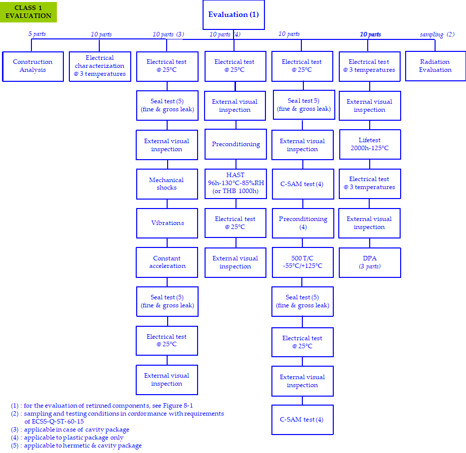 Figure 41: Evaluation tests flow chart for Class 1 components
Table 41: Evaluation Tests for Class 1 components
|
|
TEST
|
SAMPLING
|
METHOD / CRITERIA
|
COMMENTS
|
|
1
|
Construction analysis
|
5 parts
|
As per clause 4.2.2.3
See Annex H |
-
|
|
2
|
Electrical characterization
|
10 parts min
|
Electrical test under 3 T° (min, typ, max) or at using range + (whichever is higher as per 4.2.2.6).
|
Read & record for electrical test as per the preliminary issue of the internal supplier’s specification (see 4.2.3.1.k).
|
|
3
|
External visual inspection
|
10 parts min
|
ESCC 2055000
ESCC 2059000 |
|
|
4
|
Mechanical shocks
|
10 parts min
|
MIL STD 883 TM 2002 condition B - 50 pulses (per orientation) instead of 5 pulses (per orientation).
MIL-STD-750 TM 2016, 1500g, 0,5ms duration - 50 shocks instead of 5 shocks, planes X1, Y1 and Z1. |
Applicable to cavity package.
Read & record for electrical test as per the preliminary issue of the internal supplier’s specification (see 4.2.3.1.k). |
|
Vibrations
|
MIL-STD-883, TM 2007 condition A - 120 times (total) instead of 12 times (total) MIL-STD-750, TM 2056, 20g, 10-2000Hz, cross over at 50Hz - 120 times (total) instead of 12 times (total).
|
|||
|
Constant acceleration
|
MIL-STD-883, TM 2001 condition E (resultant centrifugal acceleration to be in the Y1 axis only).
For components which have a package weight of or more, or whose inner seal or cavity perimeter is more than , Condition D shall be used MIL-STD-750, TM 2006, 20000g, planes X1, Y1 and Y2. |
|||
|
5
|
Preconditioning
+ 96h HAST (or 1000h THB 85/85) |
10 parts min
|
HAST 96h-130°C-85% RH (JESD22-A110 with continuous bias) or THB (JESD22-A101) Initial and final electrical test at 25°C (parameter & functional) Preconditioning: i.a.w. JESD-22-A113 for SMD JESD-22-B106 for through hole.
|
Applicable to plastic package.
Read & record for electrical test as per the preliminary issue of the internal supplier’s specification (see 4.2.3.1.k). |
|
6
|
C-SAM
|
10 parts min
|
JEDEC J-STD-020
|
To be done on the 10 parts of step 7 after the electrical test at and before preconditioning.
C-SAM test only applicable to plastic package. |
|
7
|
Preconditioning + Thermal Cycling
|
10 parts min
|
500 T/C -55°/+ (or to the manufacturer storage temp., whichever is less) MIL-STD-750.
method 1051 cond.B MIL-STD-883 method 1010 cond.B Initial, intermediate (100 T/C) and final electrical tests at (parameter & functional). Preconditioning: i.a.w. JESD-22-A113 for SMD JESD-22-B106 for through hole. |
Preconditioning applicable to plastic package only.
Read & record for electrical tests as per the preliminary issue of the internal supplier’s specification (see 4.2.3.1.k). |
|
8
|
Seal test
|
10 parts min
|
MIL-STD-883 TM 1014 condition A or B (fine leak) and condition C (gross leak).
MIL-STD-750 TM 1071 condition H1 or H2 (fine leak) and condition C or K (gross leak with cavity) or condition E (gross leak without cavity). |
Applicable to hermetic & cavity package.
|
|
9
|
Lifetest 2000h-125°C minimum
|
10 parts min
|
MIL-STD-750 method 1026 & 1042
MIL-STD-883 method 1005 cond.D Initial, intermediate (1000h) and final electrical tests at 3 T° (min, typ, max) (parameter & functional). |
The lifetest duration shall be 2000h at minimum 125°C.
In case of a temperature lower than 125°C, the lifetest duration is extended i.a.w. MIL-STD-883 method 1005. Read & record for electrical tests. as per the preliminary issue of the internal supplier’s specification (see 4.2.3.1.k). |
|
10
|
DPA
|
3 parts
|
As per clause 4.3.9 see Annex H.
|
To be done on 3 parts after lifetest (as per above step 4).
|
|
11
|
Radiation evaluation
|
i.a.w. ECSS-Q-ST-60-15
|
See ECSS-Q-ST-60-15
|
-
|
|
4.2.4 Parts approval
| |||
|
4.2.4a
|
|
Applicable
| |
|
4.2.4b
|
|
Applicable
| |
|
4.2.4c
|
|
Applicable
| |
|
4.2.4d
|
Prior to procurement of components (or before equipment CDR, at the latest), the approval process by the customer shall be organized as follows:
|
Modified
| |
|
|
1.
|
Not applicable
| |
|
|
2.
|
Not applicable
| |
|
|
Justification Document is required in accordance with Annex F.
|
Modified
| |
|
|
4.
|
Applicable
| |
|
4.2.4e
|
In case the evaluation results are changing the testing conditions documented in the JD, a new revision of JD shall be submitted to the customer for approval.
|
Modified
| |
|
4.3 Component procurement
| |||
|
4.3.1 General
| |||
|
4.3.1a
|
|
Applicable
| |
|
4.3.1b
|
|
Not applicable
| |
|
4.3.1c
|
|
Not applicable
| |
|
4.3.1d
|
|
Applicable
| |
|
4.3.1e
|
|
Applicable
| |
|
4.3.1f
|
|
Applicable
| |
|
4.3.1g
|
|
Applicable
| |
|
4.3.1h
|
|
Applicable
| |
|
4.3.1i
|
Each procured EEE part shall be traceable to a manufacturer assigned trace code.
|
New
| |
|
4.3.1j
|
Each trace code shall be maintained as is through the entire supply chain including distributor.
|
New
| |
|
4.3.1k
|
The supplier shall ensure that the elements of the JD in accordance with Annex F, including any action plan, are applicable to flight parts.
|
New
| |
|
4.3.2. Procurement specification
| |||
|
4.3.2a
|
The supplier shall procure EEE components according to controlled specifications.
:::note It can be procurer’s in-house specification, a manufacturer’s drawing or a datasheet as a minimum. ::: |
Modified
| |
|
4.3.2b
|
|
Not applicable
| |
|
4.3.2c
|
|
Not applicable
| |
|
4.3.2d
|
|
Not applicable
| |
|
4.3.2e |
|
Applicable
| |
|
4.3.2f |
|
Applicable
| |
|
4.3.2g |
|
Applicable
| |
|
4.3.2h |
If additional requirements to the manufacturer are identified by the supplier, they shall be specified in the procurement specification, in conformance with DRD from Annex C.
|
New
| |
|
4.3.3. Screening requirements
| |||
|
4.3.3a
|
|
Applicable
| |
|
4.3.3b
|
|
Applicable
| |
|
4.3.3c
|
|
Applicable
| |
|
4.3.3d
|
For commercial parts, screening tests shall be performed in accordance with Table 42.
|
Modified
| |
|
4.3.3e
|
|
Applicable
| |
|
4.3.3f
|
|
Applicable
| |
|
4.3.3g
|
|
Applicable
| |
|
4.3.3h
|
|
Applicable
| |
Table 42: Screening tests for Class 1 components
|
|
TEST
|
SAMPLING
|
METHOD
|
COMMENTS
|
|
1
|
X-rays
|
100%
|
MIL-STD-750 method 2076 MIL-STD-883 method 2012.
|
Deposited total dose shall be< 1/10 of product acceptable dose.
|
|
2
|
Serialization
|
100%
|
Defined by the supplier.
|
-
|
|
3
|
Temperature cycling
|
100%
|
10 T/C -55°/+ (or to the manufacturer storage temp., whichever is less).
MIL-STD-750 method 1051 MIL-STD-883 method 1010 |
-
|
|
4
|
PIND test
|
100%
|
MIL-STD-750 method 2052 cond.A
MIL-STD-883 method 2020 cond.A |
Applicable to cavity package only.
|
|
5
|
Initial electrical test
|
100%
|
Electrical test (para-metrical and functional) at as per the internal supplier’s specification.
|
Read & record on selected parameters as per the internal supplier’s specification (see 4.2.3.1.k).
|
|
6
|
Burn-in
|
100%
|
MIL-STD-750 method 1038 & 1039
MIL-STd-883 method 1015 cond.B 240h – or 445h – or 885h – |
Temperature shall be < Tjmax- and Tg- whichever is lower.
In absence of Tj or Tg knowledge, max is required. Ea = 0,4eV for equivalence calculation unless a different value has been demonstrated for the product. Termination oxidation risk shall be controlled after burn-in. For discrete, HTRB and power burn-in depend on product family. |
|
7
|
Final electrical test
|
100%
|
Electrical test (para-metrical and functional) at 3 temp. as per the internal supplier’s specification.
|
Read & record on selected parameters as per the internal supplier’s specification (see 4.2.3.1k).
|
|
8
|
PDA
|
-
|
On steps 5 and 7.
Max acceptable PDA: 5% |
PDA calculation applies to room temperature measurement only.
|
|
9
|
Seal test
|
100%
|
MIL-STD-750 method 1071 cond H1 or H2 and C or K.
MIL-STD-883 method 1014 cond A or B and C. |
Applicable to hermetic & cavity package only.
|
|
10
|
External visual inspection
|
100%
|
MIL-STD-750 method 2071
MIL-STD-883 method 2009 |
The MIL specs are not adapted to visual inspection of plastic encapsulated components, but can be used as reference (mainly for connection corrosion and marking acceptance).
In addition, for plastic packages, inspect for the following defects: Package deformation/ Foreign inclusions in the package, voids and cracks in the plastic/ deformed leads. |
|
4.3.4 Initial customer source inspection (precap)
| ||
|
4.3.4a
|
|
Not applicable
|
|
4.3.4b
|
|
Not applicable
|
|
4.3.4c
|
|
Not applicable
|
|
4.3.5 Lot acceptance
| ||
|
4.3.5a
|
The supplier shall ensure that each trace code of EEE parts is submitted to a lot acceptance procedure specified in Figure 42 and Table 43 according to the following rules:
|
Modified
|
|
1.
|
Not applicable
| |
|
2.
|
Not applicable
| |
|
3. Commercial components:
|
Modified
| |
|
4.3.5b
|
|
Not applicable
|
|
4.3.5c
|
Lot acceptance of retinned components shall be performed as specified in Figure 82, from the requirement 8.1a.
|
New
|
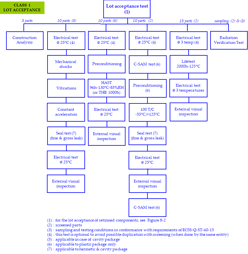 Figure 42: Lot acceptance tests flow chart for Class 1 components
Table 43: Lot acceptance tests for Class 1 components
|
|
TEST
|
SAMPLING / CRITERIA
|
METHOD
|
COMMENTS
|
|
1
|
Construction analysis
|
5 parts
|
As per clause 4.2.3.3 see Annex H.
|
-
|
|
2
|
Mechanical shocks
|
10 parts min
|
MIL STD 883 TM 2002 condition B - 50 pulses (per orientation) instead of 5 pulses (per orientation).
MIL-STD-750 TM 2016, 1500g, 0,5ms duration - 50 shocks instead of 5 shocks, planes X1, Y1 and Z1. |
Applicable to cavity package.
Read & record for electrical test as per the preliminary issue of the internal supplier’s specification (see 4.2.3.1.k). |
|
Vibrations
|
MIL-STD-883, TM 2007 condition A - 120 times (total) instead of 12 times (total).
MIL-STD-750, TM 2056, 20g, 10-2000Hz, cross over at 50Hz - 120 times (total) instead of 12 times (total). |
|||
|
Constant acceleration
|
MIL-STD-883, TM 2001 condition E (resultant centrifugal acceleration to be in the Y1 axis only).
For components which have a package weight of or more, or whose inner seal or cavity perimeter is more than , Condition D shall be used. MIL-STD-750, TM 2006, 20000g, planes X1, Y1 and Y2. |
|||
|
3
|
Preconditioning
+ 96h HAST (or 1000h THB 85/85) |
10 parts
0 defect accepted |
HAST 96h-130°C-85%RH (JESD22-A110 with continuous bias) or THB (JESD22-A101).
Electrical test (para-metrical and functional) at as per the internal supplier’s specification. Preconditioning: i.a.w. JESD-22-A113 for SMD JESD-22-B106 for through hole. |
Applicable to plastic package.
Internal supplier’s specification (see 4.2.3.1k) |
|
4
|
C-SAM
|
10 parts
|
JEDEC J-STD-020
|
To be done on the 10 parts of step 5 after the electrical test at and before preconditioning.
C-SAM test only applicable to plastic package. |
|
5
|
Preconditioning
+ Thermal Cycling [1] |
10 parts
0 defect accepted |
100 T/C -55°/+ (or to the manufacturer storage temp., whichever is less) MIL-STD-750 method 1051 cond.B MIL-STD-883 method 1010 cond.B
Electrical test (para-metrical and functional) at as per the internal supplier’s specification. Preconditioning: i.a.w. JESD-22-A113 for SMD JESD-22-B106 for through hole. |
Preconditioning applicable to plastic package only.
Internal supplier’s specification (see 4.2.3.1k) |
|
6
|
Seal test
|
10 parts min
|
MIL-STD-883 TM 1014 condition A or B (fine leak) and condition C (gross leak).
MIL-STD-750 TM 1071 condition H1 or H2 (fine leak) and condition C or K (gross leak with cavity) or condition E (gross leak without cavity). |
Applicable to hermetic & cavity package.
|
|
7
|
C-SAM
|
10 parts
|
JEDEC J-STD-020
|
To be done on the 10 parts of step 5 after thermal cycling and the electrical test at 25°C.
C-SAM test only applicable to plastic package. |
|
8
|
Lifetest [1]
|
15 parts
0 defect accepted |
2000h – 125°C minimum
MIL-STD-750 method 1026 or 1042 MIL-STD-883 method 1005 cond.D Initial, intermediate (1000h) and final electrical test (para-metrical and functional) at 3 temp as per the internal supplier’s specification |
The lifetest duration shall be 2000h at minimum 125°C.
In case of a temperature lower than 125°C, the lifetest duration is extended i.a.w. MIL-STD-883 method 1005. Can be reduced to 1000h if data 2000h are available (DC less than 2 years) and no technology change occurred. Read & record and drift calculation on selected parameters as per the internal supplier’s specification (see 4.2.3.1k). |
|
9
|
External visual inspection
|
10 parts min
|
ESCC 2055000
ESCC 2059000 |
|
|
10
|
Radiation Verification Test [1]
|
i.a.w.
ECSS-Q-ST-60-15 |
See ECSS-Q-ST-60-15
|
-
|
|
[1] : Lifetest, thermal cycling and radiation verification test are performed on screened parts (see 4.3.3).
|
||||
|
4.3.6 Final customer source inspection (buy-off)
| ||
|
4.3.6a
|
|
Not applicable
|
|
4.3.6b
|
|
Not applicable
|
|
4.3.6c
|
For commercial parts, the buy off shall be replaced by an incoming inspection at the procurement entity’s facility reported in the JD in accordance with clause 4.3.7.
|
Modified
|
|
4.3.6d
|
|
Not applicable
|
|
4.3.7 Incoming inspection
| ||
|
4.3.7a
|
|
Applicable
|
|
4.3.7b
|
|
Applicable
|
|
4.3.7c
|
|
Applicable
|
|
4.3.7d
|
|
Not applicable
|
|
4.3.7e
|
|
Applicable
|
|
4.3.8 Radiation verification testing
| ||
|
4.3.8a
|
|
Applicable
|
|
4.3.8b
|
|
Applicable
|
|
4.3.8c
|
|
Not applicable
|
|
4.3.8d
|
|
Applicable
|
|
4.3.8e
|
|
Applicable
|
|
4.3.8f
|
Parts submitted to RVT shall be first screened as specified in the clause 4.3.3 to be fully representative of flight parts.
|
New
|
|
4.3.9 Destructive physical analysis
| ||
|
4.3.9a
|
The DPA shall be performed on 3 samples per lot of commercial parts during evaluation after lifetest as specified in the clause 4.2.3.4 and after relifing as specified in the clause 4.3.10.
|
Modified
|
|
4.3.9b
|
|
Not applicable
|
|
4.3.9c
|
|
Not applicable
|
|
4.3.9d
|
|
Not applicable
|
|
4.3.9e
|
The DPA process shall be documented by a procedure to be sent, on request, to the customer for review.
|
Modified
|
|
4.3.9f
|
|
Applicable
|
|
4.3.9g
|
|
Applicable
|
|
4.3.9h
|
|
Not applicable
|
|
4.3.9i
|
|
Applicable
|
|
4.3.9j
|
|
Applicable
|
|
4.3.9k
|
A DPA shall be conducted during relifing in accordance with clause 4.3.10.
|
New
|
|
4.3.10 Relifing
| ||
|
4.3.10a
|
|
Applicable
|
|
4.3.10b
|
For components meeting the criteria specified in the requirement 4.3.10a, and which have a lot / date code exceeding 7 years, the relifing procedure ECSS-Q-ST-60-14 shall apply to the lot.
|
Modified
|
|
4.3.10c
|
Humidity test and lifetest shall be performed in accordance with the clause 4.3.5 in case these tests have not been performed on the lot during the evaluation or the procurement phase.
:::note Humidity test includes HAST or THB. ::: |
New
|
|
4.3.10d
|
As part of the relifing process, a DPA on 3 pieces shall be performed on each lot in accordance with the clause 4.3.9.
|
New
|
|
4.3.11 Manufacturer’s data documentation deliveries
| ||
|
4.3.11a
|
The manufacturer’s or the franchised distributor’s CoC shall be delivered to the parts procurer.
|
Modified
|
|
4.3.11b
|
Any other data, defined in the procurement documents, shall be delivered to the parts’ procurer in line with the purchase order.
|
Modified
|
|
4.3.11c
|
The parts procurer shall store the documentation for a minimum of 10 years after receiption of the components.
|
Modified
|
|
4.4 Handling and storage
| ||
|
4.4a
|
|
Applicable
|
|
4.4b
|
|
Applicable
|
|
4.4c
|
|
Applicable
|
|
4.4d
|
|
Applicable
|
|
4.4e
|
Plastic encapsulated devices shall be stored in one of the following conditions:
|
New
|
|
4.5 Components quality assurance
| ||
|
4.5.1 General
| ||
|
4.5.1a
|
|
Applicable
|
|
4.5.2 Nonconformances or failures
| ||
|
4.5.2a
|
|
Applicable
|
|
4.5.2b
|
|
Applicable
|
|
4.5.2c
|
|
Applicable
|
|
4.5.2d
|
|
Applicable
|
|
4.5.3 Alerts
| ||
|
4.5.3a
|
|
Applicable
|
|
4.5.3b
|
|
Applicable
|
|
4.5.3c
|
|
Applicable
|
|
4.5.4 Traceability
| ||
|
4.5.4a
|
|
Applicable
|
|
4.5.4b
|
|
Applicable
|
|
4.5.4c
|
|
Applicable
|
|
4.5.4d
|
The traceability of EEE parts during installation in equipment, shall be ensured by the supplier through maintaining the traceability to the manufacturer’s trace code number of the EEE parts actually mounted.
|
Modified
|
|
4.5.4e
|
If the as built DCL has not yet been delivered, the supplier shall be able to provide this information (part type actually installed with its relevant trace code number) within one week.
|
Modified
|
|
4.5.5 Lot homogeneity for sampling test
| ||
|
4.5.5a
|
If tests are performed by sampling, the sampled parts shall be selected so that they are representative of the trace code distribution.
|
Modified
|
|
4.5.5b
|
|
Applicable
|
|
4.6 Specific components
| ||
|
4.6.1 General
| ||
|
4.6.1a
|
<<deleted>>
|
Deleted
|
|
4.6.2 ASICs
| ||
|
4.6.2a
|
|
Applicable
|
|
4.6.3 Hybrids
| ||
|
4.6.3a
|
|
Not applicable
|
|
4.6.3b
|
|
Not applicable
|
|
4.6.3c
|
|
Not applicable
|
|
4.6.4 One time programmable devices
| ||
|
4.6.4a
|
|
Applicable
|
|
4.6.4b
|
The JD shall allow traceability to the information related to the procurement of blank parts, the programming process and the acceptance of the programmed parts.
:::note The programming process and the acceptance of the programmed parts may be part of PCB, for customer approval, if not indicated in the JD. ::: |
Modified
|
|
4.6.4c
|
<<deleted>>
|
Deleted
|
|
4.6.4d
|
|
Applicable
|
|
4.6.4e
|
|
Applicable
|
|
4.6.4f
|
|
Applicable
|
|
4.6.4g
|
|
Applicable
|
|
4.6.4h
|
|
Applicable
|
|
4.6.5 Microwave monolithic integrated circuits
| ||
|
4.6.5a
|
|
Not applicable
|
|
4.7 Documentation
| ||
|
4.7a
|
Any result from inspection or control shall be documented (including lot acceptance, incoming, relifing and complementary tests).
|
Modified
|
Table 4-4: Documentation for Class 1 components
|
Document
|
Clause
|
Customer
|
Comments
|
|
New : RFD
|
4.2.2.2
|
Approval
|
For pure tin termination
|
|
New : Procedure for hot solder dip process
|
4.2.2.2
|
Approval
|
For retinning operation
|
|
New : Internal supplier’s specification
|
4.2.3.1.i
|
Approval
|
Applicable to the preliminary and final internal supplier’s specification
|
|
PAD : not applicable
|
4.2.4
|
-
|
-
|
|
New : Justification Document
|
4.2.4
|
Approval
|
-
|
|
Procedure for customer precap : not applicable
|
4.3.4
|
-
|
-
|
|
New : Procedure for construction analysis
|
4.2.3.3
|
Approval
|
-
|
|
New : Lot acceptance report
|
4.3.5
|
Information
|
-
|
Requirements for class 2 components
|
5.1 Components programme management
| ||
|
5.1.1. General
| ||
|
5.1.1a
|
|
Applicable
|
|
5.1.2 Components control programme
| ||
|
5.1.2.1 Organization
| ||
|
5.1.2.1a
|
|
Applicable
|
|
5.1.2.2 Component control plan
| ||
|
5.1.2.2a
|
|
Applicable
|
|
5.1.2.2b
|
|
Applicable
|
|
5.1.3 Parts control board
| ||
|
5.1.3a
|
|
Applicable
|
|
5.1.3b
|
|
Applicable
|
|
5.1.3c
|
|
Applicable
|
|
5.1.3d
|
|
Applicable
|
|
5.1.4. Declared component list
| ||
|
5.1.4a
|
|
Applicable
|
|
5.1.4b
|
|
Applicable
|
|
5.1.4c
|
|
Applicable
|
|
5.1.4d
|
After equipment CDR, all modifications affecting the JD information shall be implemented, in the "as design" DCL, through the CN / CR process and submitted to the customer for approval.
|
Modified
|
|
5.1.4e
|
|
Applicable
|
|
5.1.4f
|
|
Applicable
|
|
5.1.4g
|
|
Applicable
|
|
5.1.4h
|
|
Applicable
|
|
5.1.5. Electrical and mechanical GSE
| ||
|
5.1.5a
|
|
Applicable
|
|
5.1.5b
|
|
Applicable
|
|
5.2 Component selection, evaluation and approval
| ||
|
5.2.1 General
| ||
|
5.2.1a
|
|
Applicable
|
|
5.2.1b
|
|
Applicable
|
|
5.2.2. Manufacturer and component selection
| ||
|
5.2.2.1 General rules
| ||
|
5.2.2.1a
|
|
Applicable
|
|
5.2.2.1b
|
|
Applicable
|
|
5.2.2.1c
|
|
Applicable
|
|
5.2.2.1d
|
|
Applicable
|
|
5.2.2.1e
|
For the assessment of commercial components, the supplier shall collect the available data on the manufacturer and the component in the JD. Specified in the requirement 5.2.4.d.
|
New
|
|
5.2.2.1f
|
For Deep Sub-Micron Technologies (<90nm), the detailed test definition shall identify the technology through the construction analysis and the application.
|
New
|
|
5.2.2.2. Parts and material restriction
| ||
|
5.2.2.2a
|
|
Applicable
|
|
5.2.2.2b
|
|
Applicable
|
|
5.2.2.2c
|
|
Applicable
|
|
5.2.2.2d
|
For limited life duration, known instability, safety hazards or reliability risk reasons, EEE components listed below shall not be used:
|
Modified
|
|
1. EEE components with pure tin (less than 3% Pb in case of SnPb alloy) used as a finish on the leads, terminations and external surfaces of components and packages.
|
Modified
| |
|
5.2.2.2e
|
|
Applicable
|
|
5.2.2.2f
|
|
Applicable
|
|
5.2.2.2g
|
|
Applicable
|
|
5.2.2.2h
|
The use of pure tin (inside or outside the part) shall be declared in the JD.
|
Modified
|
|
5.2.2.2i
|
To assess Pb free with tin finish whisker risk, the following actions shall be performed by the supplier:
|
New
|
|
5.2.2.3 Radiation hardness
| ||
|
5.2.2.3a
|
|
Applicable
|
|
5.2.2.3b
|
|
Applicable
|
|
5.2.2.3c
|
|
Applicable
|
|
5.2.2.3d
|
|
Applicable
|
|
5.2.2.3e
|
|
Applicable
|
|
5.2.2.3f
|
|
Applicable
|
|
5.2.2.3g
|
|
Applicable
|
|
5.2.2.3h
|
|
Applicable
|
|
5.2.2.3i
|
|
Applicable
|
|
5.2.2.4 Derating
| ||
|
5.2.2.4a
|
|
Applicable
|
|
5.2.2.4b
|
|
Applicable
|
|
5.2.2.5 Preferred sources
| ||
|
5.2.2.5.a
|
|
Applicable
|
|
5.2.2.6 Temperature range
| ||
|
5.2.2.6a
|
Commercial parts shall be selected in the highest available temperature range.
|
New
|
|
5.2.2.6b
|
A minimum margin shall be used between the maximum manufacturer temperature range and the application temperature range (including worst cases).
|
New
|
|
5.2.2.6c
|
In case |(manufacturer max temperature range – used max temp)|< , an electrical characterisation shall be performed at used temperature with an additional margin of during the evaluation step.
|
New
|
|
5.2.3 Component evaluation
| ||
|
5.2.3.1 General
| ||
|
5.2.3.1a
|
|
Applicable
|
|
5.2.3.1b
|
|
Applicable
|
|
5.2.3.1c
|
|
Applicable
|
|
5.2.3.1d
|
|
Applicable
|
|
5.2.3.1e
|
|
Applicable
|
|
5.2.3.1f
|
|
Applicable
|
|
5.2.3.1g
|
|
Applicable
|
|
5.2.3.1h
|
|
Applicable
|
|
5.2.3.1i
|
The supplier shall review the evaluation results to determine their impact on the content of the screening and lot acceptance tests.
|
Modified
|
|
5.2.3.1j
|
|
Applicable
|
|
5.2.3.1k
|
The supplier shall prepare a preliminary internal supplier’s specification for electrical testing during evaluation tests.
|
New
|
|
5.2.3.1l
|
The supplier specification specified in 5.2.3.1k shall as minimum include test parameters, test conditions, acceptance criteria, drift limits.
|
New
|
|
5.2.3.1m
|
The supplier shall update the internal supplier’s specification used for screening and lot acceptance in accordance with the results of evaluation testing.
|
New
|
|
5.2.3.1n
|
The preliminary and the final internal supplier’s specification as specified in Annex C shall be submitted to the customer for approval.
|
New
|
|
5.2.3.2 Component manufacturer assessment
| ||
|
5.2.3.2a
|
|
Not applicable
|
|
5.2.3.3. Construction analysis
| ||
|
5.2.3.3a
|
|
Applicable
|
|
5.2.3.3b
|
The Construction analysis shall be documented by a procedure to be sent to the customer for approval.
:::note Annex H provides guidelines for such procedure. ::: |
Modified
|
|
5.2.3.3c
|
|
Applicable
|
|
5.2.3.4. Evaluation testing
| ||
|
5.2.3.4a
|
|
Applicable
|
|
5.2.3.4b
|
|
Applicable
|
|
5.2.3.4c
|
Evaluation tests shall be performed as specified in Figure 51 and Table 51.
|
New
|
|
5.2.3.4d
|
Omission of any of the elements of tests specified in Figure 51 and Table 51, or the introduction of alternative activities, shall be justified in the JD.
|
New
|
|
5.2.3.4e
|
Evaluation of retinned components shall be performed as specified in Figure 83 from the requirement 8.1a.
|
New
|
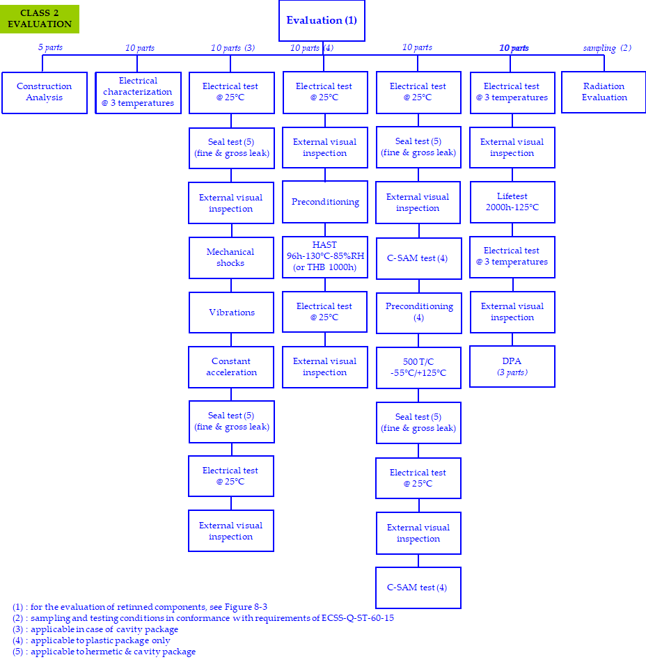 Figure 51: Evaluation Tests flow charts for Class 2 components
Table 51: Evaluation Tests for Class 2 components
|
|
TEST
|
SAMPLING
|
METHOD / CRITERIA
|
COMMENTS
|
|
1
|
Construction analysis
|
5 parts
|
As per clause 4.2.2.3
See Annex H |
-
|
|
2
|
Electrical characterization
|
10 parts min
|
Electrical test under 3 T° (min, typ, max) or at using range + (whichever is higher as per 4.2.2.6).
|
Read & record for electrical test as per the preliminary issue of the internal supplier’s specification (see 4.2.3.1.k).
|
|
3
|
External visual inspection
|
10 parts min
|
ESCC 2055000
ESCC 2059000 |
|
|
4
|
Mechanical shocks
|
10 parts min
|
MIL STD 883 TM 2002 condition B - 50 pulses (per orientation) instead of 5 pulses (per orientation).
MIL-STD-750 TM 2016, 1500g, 0,5ms duration - 50 shocks instead of 5 shocks, planes X1, Y1 and Z1. |
Applicable to cavity package.
Read & record for electrical test as per the preliminary issue of the internal supplier’s specification (see 4.2.3.1.k). |
|
Vibrations
|
MIL-STD-883, TM 2007 condition A - 120 times (total) instead of 12 times (total).
MIL-STD-750, TM 2056, 20g, 10-2000Hz, cross over at 50Hz - 120 times (total) instead of 12 times (total). |
|||
|
Constant acceleration
|
MIL-STD-883, TM 2001 condition E (resultant centrifugal acceleration to be in the Y1 axis only).
For components which have a package weight of or more, or whose inner seal or cavity perimeter is more than , Condition D shall be used. MIL-STD-750, TM 2006, 20000g, planes X1, Y1 and Y2. |
|||
|
5
|
Preconditioning
+ 96h HAST (or 1000h THB 85/85) |
10 parts min
|
HAST 96h-130°C-85%RH (JESD22-A110 with continuous bias) or THB (JESD22-A101) Initial and final electrical test at 25°C (parameter & functional) Preconditioning: i.a.w. JESD-22-A113 for SMD JESD-22-B106 for through hole.
|
Applicable to plastic package.
Read & record for electrical test as per the preliminary issue of the internal supplier’s specification (see 4.2.3.1.k). |
|
6
|
C-SAM
|
10 parts min
|
JEDEC J-STD-020
|
To be done on the 10 parts of step 7 after the electrical test at and before preconditioning.
C-SAM test only applicable to plastic package. |
|
7
|
Preconditioning + Thermal Cycling
|
10 parts min
|
500 T/C -55°/+ (or to the manufacturer storage temp., whichever is less) MIL-STD-750.
method 1051 cond.B MIL-STD-883 method 1010 cond.B Initial, intermediate (100 T/C) and final electrical tests at (parameter & functional). Preconditioning: i.a.w. JESD-22-A113 for SMD JESD-22-B106 for through hole. |
Preconditioning applicable to plastic package only.
Read & record for electrical tests as per the preliminary issue of the internal supplier’s specification (see 4.2.3.1.k). |
|
8
|
Seal test
|
10 parts min
|
MIL-STD-883 TM 1014 condition A or B (fine leak) and condition C (gross leak).
MIL-STD-750 TM 1071 condition H1 or H2 (fine leak) and condition C or K (gross leak with cavity) or condition E (gross leak without cavity). |
Applicable to hermetic & cavity package.
|
|
9
|
Lifetest 2000h-125°C minimum
|
10 parts min
|
MIL-STD-750 method 1026 & 1042.
MIL-STD-883 method 1005 cond.D Initial, intermediate (1000h) and final electrical tests at 3 T° (min, typ, max) (parameter & functional). |
The lifetest duration shall be 2000h at minimum 125°C.
In case of a temperature lower than 125°C, the lifetest duration is extended i.a.w. MIL-STD-883 method 1005. Read & record for electrical tests. as per the preliminary issue of the internal supplier’s specification (see 4.2.3.1.k). |
|
10
|
DPA
|
3 parts
|
As per clause 4.3.9 see Annex H.
|
To be done on 3 parts after lifetest (as per above step 4).
|
|
11
|
Radiation evaluation
|
i.a.w.
ECSS-Q-ST-60-15 |
See ECSS-Q-ST-60-15
|
-
|
|
5.2.4 Parts approval
| ||
|
5.2.4a
|
|
Applicable
|
|
5.2.4b
|
|
Applicable
|
|
5.2.4c
|
|
Applicable
|
|
5.2.4d
|
Prior to procurement of components (or before equipment CDR, at the latest), the approval process by the customer shall be organized as follows:
|
Modified
|
|
1
|
Not applicable
| |
|
2
|
Not applicable
| |
|
3
|
Not applicable
| |
|
Justification Document is required in accordance with annex F.
|
Modified
| |
|
5.2.4e
|
In case the evaluation results are changing the testing conditions documented in the JD, a new revision of JD shall be submitted to the customer for approval.
|
Modified
|
|
5.3 Component procurement
| ||
|
5.3.1 General
| ||
|
5.3.1a
|
|
Applicable
|
|
5.3.1b
|
|
Not applicable
|
|
5.3.1c
|
|
Not applicable
|
|
5.3.1d
|
|
Applicable
|
|
5.3.1e
|
|
Applicable
|
|
5.3.1f
|
|
Applicable
|
|
5.3.1g
|
|
Applicable
|
|
5.3.1h
|
|
Applicable
|
|
5.3.1i
|
Each procured EEE part shall be traceable to a manufacturer assigned trace code.
|
New
|
|
5.3.1j
|
Each trace code shall be maintained as is through the entire supply chain including distributor.
|
New
|
|
5.3.1k
|
The supplier shall ensure that the elements of the JD in accordance with Annex F, including any action plan, are applicable to flight parts.
|
New
|
|
5.3.2 Procurement specification
| ||
|
5.3.2a
|
The supplier shall procure EEE components according to controlled specifications.
:::note It can be procurer’s in-house specification, a manufacturer’s drawing or a datasheet as a minimum. ::: |
Modified
|
|
5.3.2b
|
|
Not applicable
|
|
5.3.2c
|
|
Not applicable
|
|
5.3.2d
|
|
Not applicable
|
|
5.3.2e
|
|
Applicable
|
|
5.3.2f
|
|
Applicable
|
|
5.3.2g
|
|
Applicable
|
|
5.3.2h
|
If aditional requirements to the manufacturer are identified, they shall be specified in the procurement specification.
|
New
|
|
5.3.3 Screening requirements
| ||
|
5.3.3a
|
|
Applicable
|
|
5.3.3b
|
|
Applicable
|
|
5.3.3c
|
|
Applicable
|
|
5.3.3d
|
For commercial parts, screening tests shall be performed in accordance with Table 52.
|
Modified
|
|
5.3.3e
|
|
Applicable
|
|
5.3.3f
|
|
Applicable
|
|
5.3.3g
|
|
Applicable
|
|
5.3.3h
|
|
Applicable
|
|
5.3.3.i
|
Based on data from the evaluation tests in conformance with the requirement 5.2.3.4 and data collected in the JD, the supplier may propose a modification of the screening flow of table 5-2, to be submitted to customer for approval.
:::note Data collected in the JD includes EFR, life test, thermal cycling. ::: |
New
|
|
5.3.3.j
|
If modification of 5.3.3f is proposed to the customer, it shall meet the following similarity criteria:
1. For EFR, either: (a) the data are as the same die revision, wafer fab, process and package. (b) the data are not provided, but in this case the data on the same part type is not older than two years w.r.t date code. 2. For lifetest, either: (a) the data are as the same die revision, wafer fab, process and pacakge. (b) the data are not provided, but in this case the data on the same part type is not older thant two years w.r.t date code. 3. For thermal cycles the data are on same package. |
New
|
|
5.3.3.k
|
100% Pind test and 100% hermeticity test (when applicable) shall not be tailored out of the screening flow.
|
New
|
|
5.3.3.l
|
100% external visual inspection shall be performed in case of any test done during screening or in case of retinning.
|
New
|
Table 52: Screening tests for the Class 2 components
|
|
TEST
|
SAMPLING
|
METHOD
|
COMMENTS
|
|
1
|
Serialization
|
100%
|
Defined by the supplier.
|
-
|
|
2
|
Temperature cycling
|
100%
|
10 T/C -55°/+ (or to the manufacturer storage temp., whichever is less).
MIL-STD-750 method 1051 MIL-STD-883 method 1010 |
-
|
|
3
|
PIND test
|
100%
|
MIL-STD-750 method 2052 cond.A
MIL-STD-883 method 2020 cond.A |
Applicable to cavity package only.
|
|
4
|
Initial electrical test
|
100%
|
Electrical test (parametrical and functional) at as per the internal supplier’s specification.
|
Read & record on selected parameters as per the internal supplier’s specification (see 5.2.3.1k).
|
|
5
|
Burn-in
|
100%
|
MIL-STD-750 method 1038 & 1039
MIL-STD-883 method 1015 cond.B 160h – or 300h – or 590h – |
Temperature shall be < Tjmax- and Tg- whichever is lower.
In absence of Tj or Tg knowledge, max is required. Ea = 0,4eV for equivalence calculation unless a different value has been demonstrated for the product. Termination oxidation risk shall be controlled after burn-in. For discrete, HTRB and power burn-in depend on product family. |
|
6
|
Final electrical test
|
100%
|
Electrical test (para-metrical and functional) at 3 temp.as per the internal supplier’s specification.
|
Read & record on selected parameters as per the internal supplier’s specification (see 5.2.3.1k).
|
|
7
|
PDA
|
-
|
On steps 4 and 6.
Max acceptable PDA: 5% |
PDA calculation applies to room temperature measurement only.
|
|
8
|
Seal test
|
100%
|
MIL-STD-750 method 1071 cond H1 or H2 and C or K.
MIL-STD-883 method 1014 cond A or B and C. |
Applicable to hermetic & cavity package only.
|
|
9
|
External visual inspection
|
100%
|
MIL-STD-750 method 2071
MIL-STD-883 method 2009 |
The MIL specs are not adapted to visual inspection of plastic encapsulated components, but can be used as reference (mainly for connection corrosion and marking acceptance).
In addition, for plastic packages, inspect for the following defects: Package deformation/ Foreign inclusions in the package, voids and cracks in the plastic/ deformed leads. |
|
5.3.4 Initial customer source inspection (precap)
| ||
|
5.3.4a
|
|
Not applicable
|
|
5.3.4b
|
|
Not applicable
|
|
5.3.5 Lot acceptance
| ||
|
5.3.5a
|
The supplier shall ensure that each trace code of EEE parts is submitted to a lot acceptance procedure specified in Figure 52 and Table 53 according to the following rules:
|
Modified
|
|
1.
|
Not applicable
| |
|
2.
|
Not applicable
| |
|
3. Commercial components:
|
Modified
| |
|
5.3.5b
|
|
Not applicable
|
|
5.3.5c
|
Lot acceptance of retinned components shall be performed as specified in Figure 84 from requirement 8.1a.
|
New
|
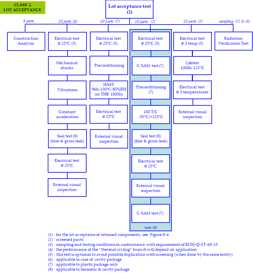 Figure 52: Lot acceptance tests flow chart for Class 2 components
Table 53: Lot acceptance tests for Class 2 components
|
|
TEST
|
SAMPLING / CRITERIA
|
METHOD
|
COMMENTS
|
|
1
|
Construction analysis
|
5 parts
|
As per clause 5.2.3.3 see Annex H.
|
-
|
|
2
|
Mechanical shocks
|
10 parts min
|
MIL STD 883 TM 2002 condition B - 50 pulses (per orientation) instead of 5 pulses (per orientation).
MIL-STD-750 TM 2016, 1500g, 0,5ms duration - 50 shocks instead of 5 shocks, planes X1, Y1 and Z1. |
Applicable to cavity package.
Read & record for electrical test as per the preliminary issue of the internal supplier’s specification (see 5.2.3.1.k). |
|
Vibrations
|
MIL-STD-883, TM 2007 condition A - 120 times (total) instead of 12 times (total).
MIL-STD-750, TM 2056, 20g, 10-2000Hz, cross over at 50Hz - 120 times (total) instead of 12 times (total). |
|||
|
Constant acceleration
|
MIL-STD-883, TM 2001 condition E (resultant centrifugal acceleration to be in the Y1 axis only).
For components which have a package weight of or more, or whose inner seal or cavity perimeter is more than , Condition D shall be used MIL-STD-750, TM 2006, 20000g, planes X1, Y1 and Y2. |
|||
|
3
|
Preconditioning
+ 96h HAST (or 1000h THB 85/85) |
10 parts
0 defect accepted |
HAST 96h-130°C-85%RH (JESD22-A110 with continuous bias) or THB (JESD22-A101).
Electrical test (para-metrical and functional) at as per the internal supplier’s specification Preconditioning: i.a.w. JESD-22-A113 for SMD JESD-22-B106 for through hole. |
Only for plastic package.
Internal supplier’s specification (see 5.2.3.1k). |
|
4
|
C-SAM
|
10 parts
|
JEDEC J-STD-020
|
To be done on the 10 parts of step 5 after the electrical test at and before preconditioning.
C-SAM test only applicable to plastic package. |
|
5
|
Preconditioning
+ Thermal Cycling [1] |
10 parts
0 defect accepted |
100 T/C -55°/+ (or to the manufacturer storage temp., whichever is less) MIL-STD-750 method 1051 cond.B MIL-STD-883 method 1010 cond.B.
Electrical test (para-metrical and functional) at as per the internal supplier’s specification. Preconditioning: i.a.w. JESD-22-A113 for SMD JESD-22-B106 for through hole. |
Preconditioning applicable to plastic package only.
The necessity to perform this step will depend on the application.
|
|
6
|
Seal test
|
10 parts min
|
MIL-STD-883 TM 1014 condition A or B (fine leak) and condition C (gross leak).
MIL-STD-750 TM 1071 condition H1 or H2 (fine leak) and condition C or K (gross leak with cavity) or condition E (gross leak without cavity). |
Applicable to hermetic & cavity package.
|
|
7
|
C-SAM
|
10 parts
|
JEDEC J-STD-020
|
To be done on the 10 parts of step 5 after thermal cycling and the electrical test at 25°C.
C-SAM test only applicable to plastic package. |
|
8
|
Lifetest [1]
|
15 parts
0 defect accepted |
1000h – 125°C minimum
MIL-STD-750 method 1026 or 1042 MIL-STD-883 method 1005 cond.D Initial, intermediate and final electrical test (para-metrical and functional) at 3 temp as per the internal supplier’s specification. |
The lifetest duration shall be 1000h at minimum 125°C.
In case a temperature lower than 125°C, the lifetest duration is extended i.a.w. MIL-STD-883 method 1005. Read & record and drift calculation on selected parameters as per the internal supplier’s specification (see 5.2.3.1k) |
|
9
|
External visual inspection
|
10 parts min
|
ESCC 2055000
ESCC 2059000 |
|
|
10
|
Radiation Verification Test [1]
|
i.a.w.
ECSS-Q-ST-60-15 |
See ECSS-Q-ST-60-15
|
-
|
|
[1] : Lifetest, thermal cycling and radiation verification test are performed on screened parts (see 5.3.3).
|
||||
|
5.3.6 Final customer source inspection (buy-off)
| ||
|
5.3.6a
|
|
Not applicable
|
|
5.3.6b
|
|
Not applicable
|
|
5.3.6c
|
For commercial parts, the buy off shall be replaced by an incoming inspection at the procurement entity’s facility reported in the JD in accordance with clause 5.3.7.
|
Modified
|
|
5.3.6d
|
|
Not applicable
|
|
5.3.7 Incoming inspection
| ||
|
5.3.7a
|
|
Applicable
|
|
5.3.7b
|
|
Applicable
|
|
5.3.7c
|
|
Applicable
|
|
5.3.7d
|
|
Not Applicable
|
|
5.3.7e
|
|
Applicable
|
|
5.3.8 Radiation verification testing
| ||
|
5.3.8a
|
|
Applicable
|
|
5.3.8b
|
|
Applicable
|
|
5.3.8c
|
|
Not applicable
|
|
5.3.8d
|
|
Applicable
|
|
5.3.8e
|
|
Applicable
|
|
5.3.8f
|
Parts submitted to RVT shall be screened as specified in clause 5.3.3 to be fully representative of flight parts.
|
New
|
|
5.3.9 Destructive physical analysis
| ||
|
5.3.9a
|
The DPA shall be performed on 3 samples per lot of commercial parts (during evaluation after lifetest as specified in clause 5.2.3.4 and after relifing as specified by clause 5.3.10).
:::note Annex H provides guidelines for the construction analysis and destructive physical analysis. ::: |
Modified
|
|
5.3.9b
|
|
Not applicable
|
|
5.3.9c
|
|
Not applicable
|
|
5.3.9d
|
The DPA process shall be documented by a procedure to be sent, on request, to the customer for review.
|
Modified
|
|
5.3.9e
|
|
Applicable
|
|
5.3.9f
|
|
Applicable
|
|
5.3.9g
|
|
Not applicable
|
|
5.3.9h
|
|
Applicable
|
|
5.3.9i
|
|
Applicable
|
|
5.3.9j
|
A DPA shall be conducted during relifing in accordance with clause 5.3.10.
|
New
|
|
5.3.10 Relifing
| ||
|
5.3.10a
|
|
Applicable
|
|
5.3.10b
|
For components meeting the criteria specified in requirement 5.3.10a, and which have a lot / date code exceeding 7 years, the relifing procedure ECSS-Q-ST-60-14 shall apply to the lot.
|
Modified
|
|
5.3.10c
|
Humidity test and lifetest shall be performed in accordance with the clause 5.3.5 in case these tests have not been performed on the lot during the evaluation or the procurement phase.
:::note Humidity test include HAST or THB. ::: |
New
|
|
5.3.10d
|
As part of the relifing process, a DPA on 3 pieces shall be performed on each lot in accordance with the clause 5.3.9.
|
New
|
|
5.3.11 Manufacturer’s data documentation deliveries
| ||
|
5.3.11a
|
The manufacturer’s or the franchised distributor’s CoC shall be delivered to the parts procurer.
|
Modified
|
|
5.3.11b
|
Any other data, defined in the procurement documents, shall be delivered to the parts’ procurer in line with the purchase order.
|
Modified
|
|
5.3.11c
|
The parts procurer shall store the documentation minimum 10 years after receiption of the components.
|
Modified
|
|
5.4 Handling and storage
| ||
|
5.4a
|
|
Applicable
|
|
5.4b
|
|
Applicable
|
|
5.4c
|
|
Applicable
|
|
5.4d
|
|
Applicable
|
|
5.4e
|
Plastic encapsulated devices shall be stored in one of the following conditions:
|
New
|
|
5.5 Components quality assurance
| ||
|
5.5.1 General
| ||
|
5.5.1a
|
|
Applicable
|
|
5.5.2 Nonconformances or failures
| ||
|
5.5.2a
|
|
Applicable
|
|
5.5.2b
|
|
Applicable
|
|
5.5.2c
|
|
Applicable
|
|
5.5.2d
|
|
Applicable
|
|
5.5.3 Alerts
| ||
|
5.5.3a
|
|
Applicable
|
|
5.5.3b
|
|
Applicable
|
|
5.5.4 Traceability
| ||
|
5.5.4a
|
|
Applicable
|
|
5.5.4b
|
|
Applicable
|
|
5.5.4c
|
|
Applicable
|
|
5.5.4d
|
The traceability of EEE parts during installation in equipment, shall be ensured by the supplier through maintaining the traceability to the manufacturer’s trace code number of the EEE parts actually mounted.
|
Modified
|
|
5.5.4e
|
If the as built DCL has not yet been delivered, the supplier shall be able to provide this information (part type actually installed with its relevant trace code number) within one week.
|
Modified
|
|
5.5.5 Lot homogeneity for sampling test
| ||
|
5.5.5a
|
|
Applicable
|
|
5.6 Specific components
| ||
|
5.6.1 General
| ||
|
5.6.1a
|
<<deleted>>
|
Deleted
|
|
5.6.2 ASICs
| ||
|
5.6.2a
|
|
Applicable
|
|
5.6.3 Hybrids
| ||
|
5.6.3a
|
|
Not applicable
|
|
5.6.3b
|
|
Not applicable
|
|
5.6.3c
|
|
Not applicable
|
|
5.6.4 One time programmable devices
| ||
|
5.6.4a
|
|
Applicable
|
|
5.6.4b
|
The JD shall allow traceability to the information related to the procurement of blank parts, the programming process and the acceptance of the programmed parts.
|
Modified
|
|
5.6.4c
|
The programming process and the acceptance of the programmed parts may be part of PCB, for customer approval, if not indicated in the JD.
|
Modified
|
|
5.6.4d
|
|
Applicable
|
|
5.6.4e
|
|
Applicable
|
|
5.6.4f
|
|
Applicable
|
|
5.6.4g
|
|
Applicable
|
|
5.6.4h
|
|
Applicable
|
|
5.6.5 Microwave monolithic integrated circuits
| ||
|
5.6.5a
|
|
Not applicable
|
|
5.7 Documentation
| ||
|
5.7a
|
Any result from inspection or control shall be documented (including lot acceptance, incoming, relifing and complementary tests).
|
Modified
|
Table 54: Documentation for Class 2 components
|
Document
|
Clause
|
Customer
|
Comments
|
|
New : RFD
|
5.2.2.2
|
Approval
|
For pure tin termination.
|
|
New :Pure tin lead finish risk analysis
|
5.2.2.2
|
Information
|
In accordance with clause 8.2a.
|
|
New :
|
5.2.2.2
|
Approval
|
Approved through the RFD.
|
|
New : Procedure for hot solder dip process
|
5.2.2.2
|
Approval
|
For retinning operation.
|
|
New : Internal supplier’s specification
|
5.2.3.1.i
|
Approval
|
Applicable to the preliminary and final internal supplier’s specification.
|
|
PAD : not applicable
|
5.2.4
|
-
|
-
|
|
New : Justification Document
|
5.2.4
|
Approval
|
-
|
|
New : Procedure for screening flow
|
5.3.3
|
Approval
|
-
|
|
Procedure for customer precap : not applicable
|
5.3.4
|
-
|
-
|
|
New : Procedure for construction analysis
|
5.2.3.3
|
Approval
|
-
|
|
New : Lot acceptance report
|
5.3.5
|
Information
|
-
|
Requirements for class 3 components
|
6.1 Component programme management
| |||
|
6.1.1. General
| |||
|
6.1.1a |
|
Applicable |
|
|
6.1.2 Components control programme
| |||
|
6.1.2.1 Organization
| |||
|
6.1.2.1a |
|
Applicable |
|
|
6.1.2.2 Component control plan
| |||
|
6.1.2.2a |
|
Applicable |
|
|
6.1.2.2b |
|
Applicable |
|
|
6.1.3 Parts control board
| |||
|
6.1.3a |
|
Applicable |
|
|
6.1.4 Declared component list
| |||
|
6.1.4a |
|
Applicable |
|
|
6.1.4b |
|
Applicable |
|
|
6.1.4c |
|
Applicable |
|
|
6.1.4d |
After equipment CDR, all modifications affecting the JD information shall be implemented, in the "as design" DCL, through the CN / CR process and submitted to the customer for approval.
|
Modified |
|
|
6.1.4e |
|
Applicable |
|
|
6.1.4f |
|
Applicable |
|
|
6.1.4g |
|
Applicable |
|
|
6.1.5 Electrical and mechanical GSE
| |||
|
6.1.5a |
|
Applicable |
|
|
6.1.5b |
|
Applicable |
|
|
6.2 Component selection, evaluation and approval |
|||
|
6.2.1 General
| |||
|
6.2.1a |
|
Applicable |
|
|
6.2.1b |
|
Applicable |
|
|
6.2.2 Manufacturer and component selection
| |||
|
6.2.2.1 General rules
| |||
|
6.2.2.1a |
|
Applicable |
|
|
6.2.2.1b |
|
Applicable |
|
|
6.2.2.1c |
|
Applicable |
|
|
6.2.2.1d |
|
Applicable |
|
|
6.2.2.1e |
For the assessment of commercial components, the supplier shall collect the available data on the manufacturer and the component in the JD specified in the requirement 6.2.4.d.
|
New |
|
|
6.2.2.1f |
For Deep Sub-Micron Technologies (<90nm) the detailed test definition shall identify the technology through the construction analysis and the application.
|
New |
|
|
6.2.2.2 Parts and material restriction
| |||
|
6.2.2.2a |
|
Applicable |
|
|
6.2.2.2b |
|
Applicable |
|
|
6.2.2.2c |
|
Applicable |
|
|
6.2.2.2d |
For limited life duration, known instability, safety hazards or reliability risk reasons, EEE components listed below shall not be used:
|
Modified |
|
|
6.2.2.2e |
|
Applicable |
|
|
6.2.2.2f |
|
Applicable |
|
|
6.2.2.2g |
|
Applicable |
|
|
6.2.2.2h |
The use of pure tin (inside or outside the part) shall be declared in the JD.
|
Modified |
|
|
6.2.2.2i |
To assess Pb free with tin finish whisker risk, the following actions shall be performed by the supplier:
|
New |
|
|
6.2.2.3 Preferred sources
| |||
|
6.2.2.3a |
|
Applicable |
|
|
6.2.2.4 Radiation hardness
| |||
|
6.2.2.4a |
|
Applicable |
|
|
6.2.2.4b |
|
Applicable |
|
|
6.2.2.4c |
|
Applicable |
|
|
6.2.2.4d |
|
Applicable |
|
|
6.2.2.4e |
|
Applicable |
|
|
6.2.2.4f |
|
Applicable |
|
|
6.2.2.4g |
|
Applicable |
|
|
6.2.2.4h |
|
Applicable |
|
|
6.2.2.4i |
|
Applicable |
|
|
6.2.2.5 Derating
| |||
|
6.2.2.5a |
|
Applicable |
|
|
6.2.2.5b |
|
Applicable |
|
|
6.2.2.6 Temperature range
| |||
|
6.2.2.6a |
Commercial parts shall be selected in the highest available temperature range.
|
New |
|
|
6.2.2.6b |
A minimum margin shall be used between the maximum manufacturer temperature range and the application temperature range (including worst cases).
|
New |
|
|
6.2.2.6c |
In case |(manufacturer max temperature range – used max temp)|< , an electrical characterisation shall be performed at used temperature with an additional margin of during the evaluation step.
|
New |
|
|
6.2.3 Component evaluation
| |||
|
6.2.3.1 General
| |||
|
6.2.3.1a |
For class 3 components, the evaluation shall be limited to construction analysis and radiation tests.
|
Modified |
|
|
6.2.3.1b |
|
Applicable |
|
|
6.2.3.1c |
|
Not applicable |
|
|
6.2.3.1d |
An evaluation plan shall be sent to the customer for approval, and include the following elements:
|
Modified |
|
|
1. Construction Analysis
|
Applicable |
||
|
2. Evaluation testing
|
Not applicable |
||
|
3. Radiation Hardness
|
Applicable |
||
|
6.2.3.1e |
|
Applicable |
|
|
6.2.3.1f |
|
Applicable |
|
|
6.2.3.1g |
|
Applicable |
|
|
6.2.3.1h |
|
Applicable |
|
|
6.2.3.1i |
The supplier shall review the evaluation results to determine their impact on the content of the lot acceptance tests.
|
Modified |
|
|
6.2.3.1j |
|
Applicable |
|
|
6.2.3.2 Component manufacturer assessment
| |||
|
6.2.3.2a |
|
Not applicable See 6.2.2.1e |
|
|
6.2.3.3. Construction analysis
| |||
|
6.2.3.3a |
|
Applicable |
|
|
6.2.3.3b |
The Construction analysis shall be documented by a procedure to be sent to the customer for approval.
:::note Annex H provides guidelines for such procedure. ::: |
Modified |
|
|
6.2.3.3c |
|
Applicable |
|
|
6.2.3.4 Evaluation testing
| |||
|
6.2.3.4a |
|
Not applicable |
|
|
6.2.3.4b |
|
Not applicable |
|
|
6.2.3.4c |
Evaluation tests shall be performed as specified in Table 61.
|
New |
|
|
6.2.3.4d |
Omission of any of the elements of tests specified in Table 61, or the introduction of alternative activities, shall be justified in the JD.
|
New |
|
|
6.2.3.4.e |
Evaluation of retinned components shall be performed in accordance with Figure 85 from the requirement 8.1a.
|
New |
|
Table 61: Evaluation tests for Class 3 components
|
|
TEST
|
SAMPLING
|
METHOD / CRITERIA
|
COMMENTS
|
|
1
|
Construction analysis
|
5 parts
|
As per clause 6.2.3.3
|
-
|
|
2
|
Radiation evaluation
|
i.a.w.
|
See ECSS-Q-ST-60-15
|
-
|
|
6.2.4 Parts approval |
||
|
6.2.4a |
|
Applicable |
|
6.2.4b |
|
Applicable |
|
6.2.4c |
|
Applicable |
|
6.2.4d |
Prior to procurement of components (or before equipment CDR, at the latest), the approval process by the customer shall be organized as follows:
|
Modified |
|
1.
|
Not applicable |
|
|
2.
|
Not applicable |
|
|
3. A Justification Document is required in accordance with Annex F.
|
Modified |
|
|
6.2.4e |
In case the evaluation results are changing the testing conditions documented in the JD, a new revision of JD shall be submitted to the customer for approval. |
Modified |
|
6.3 Component procurement |
||
|
6.3.1 General |
||
|
6.3.1a |
|
Applicable |
|
6.3.1b |
|
Not applicable |
|
6.3.1c |
|
Not applicable |
|
6.3.1d |
|
Applicable |
|
6.3.1e |
|
Applicable |
|
6.3.1f |
Each procured EEE part shall be traceable to a manufacturer assigned trace code.
|
New |
|
6.3.1g |
Each trace code shall be maintained as is through the entire supply chain including distributor.
|
New |
|
6.3.1h |
The supplier shall ensure that the elements of the JD in accordance with Annex F, including any action plan, are applicable to flight parts.
|
New |
|
6.3.2 Procurement specification |
||
|
6.3.2a |
The supplier shall procure EEE components according to controlled specifications.
:::note It can be procurer’s in-house specification, a manufacturer’s drawing or a datasheet as a minimum. ::: |
Modified |
|
6.3.2b |
|
Not applicable |
|
6.3.2c |
|
Not applicable |
|
6.3.2d |
|
Not applicable |
|
6.3.2e |
|
Applicable |
|
6.3.2f |
|
Applicable |
|
6.3.2g |
|
Applicable |
|
6.3.2h |
If additional requirements are specified to the manufacturer, they shall be identified in a procurement specification.
|
New |
|
6.3.3 Screening requirements |
||
|
6.3.3a |
|
Applicable |
|
6.3.3b |
|
Applicable |
|
6.3.3c |
|
Applicable |
|
6.3.3d |
For commercial parts, screening tests shall be performed in accordance with Table 62.
|
Modified |
|
6.3.3e |
|
Applicable |
|
6.3.3f |
|
Applicable |
|
6.3.3g |
|
Applicable |
|
6.3.3h |
|
Applicable |
Table 62: Screening tests for Class 3 components
|
|
TEST |
SAMPLING |
METHOD |
COMMENTS |
|
1 |
PIND test
|
100%
|
MIL-STD-750 method 2052 cond.A
MIL-STD-883 method 2020 cond.A |
Applicable to cavity package only.
|
|
2 |
Seal test
|
100%
|
MIL-STD-750 method 1071 cond H1 or H2 and C or K.
MIL-STD-883 method 1014 cond A or B and C. |
Applicable to hermetic & cavity package only.
In case of retinning, test to be done after retinning. |
|
3 |
Electrical test
|
100%
|
Electrical test (para-metrical and functional) at 3 temp. as per the datasheet (selected functional tests and parameters).
|
To be done only in case of retinning.
|
|
4 |
PDA
|
-
|
On steps 3.
Max acceptable PDA: 5% |
To be done only in case of retinning. PDA calculation applies to room temperature measurement only.
|
|
5 |
External visual inspection
|
100%
|
MIL-STD-750 method 2071
MIL-STD-883 method 2009 |
To be done only in case of retinning. The MIL specs are not adapted to visual inspection of plastic encapsulated components, but can be used as reference (mainly for connection corrosion and marking acceptance).
In addition, for plastic packages, inspect for the following defects: Package deformation/ Foreign inclusions in the package, voids and cracks in the plastic/ deformed leads. |
|
6.3.4 Initial customer source inspection (precap)
| ||
|
6.3.4a |
|
Applicable |
|
6.3.5 Lot acceptance
| ||
|
6.3.5a |
The supplier shall ensure that each trace code of EEE parts is submitted to a lot acceptance procedure specified in Figure 61 and Table 63 according to the following rules:
|
Modified |
|
1.
|
Not applicable |
|
|
2.
|
Not applicable |
|
|
3. Commercial components:
|
Modified |
|
|
6.3.5b |
|
Not applicable |
|
6.3.5c |
Lot acceptance of retinned components shall be performed as specified in Figure 86 from the requirement 8.1a.
|
New |
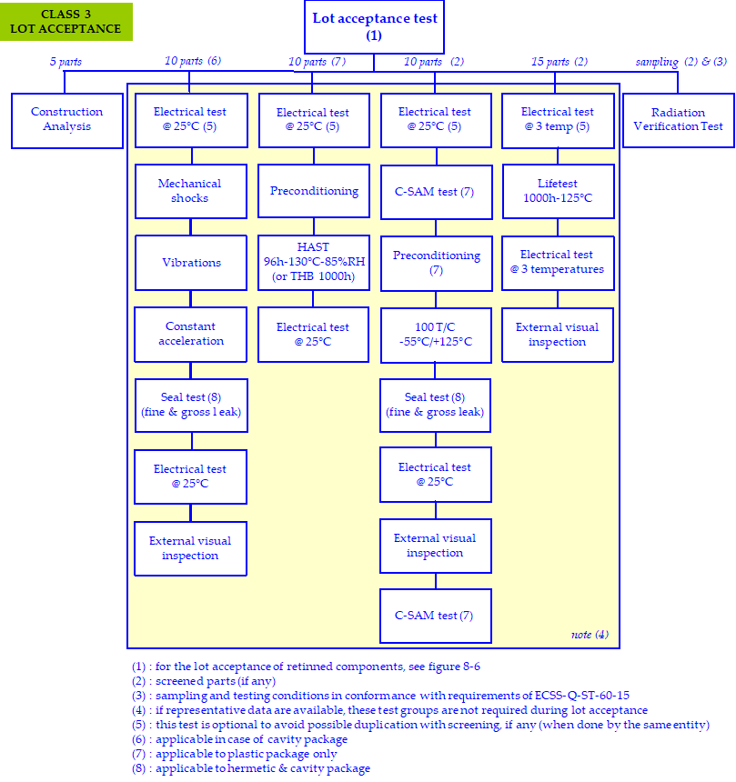 Figure 61: Lot acceptance test flow chart for Class 3 components
Table 63: Lot acceptance tests for Class 3 components
|
|
TEST
|
SAMPLING / CRITERIA
|
METHOD
|
COMMENTS
|
|
1
|
Construction analysis
|
5 parts
|
As per clause 6.2.3.3
|
In case of retinning, step 1 shall include the SEM “QBSD” mode to check the 100% coverage of SnPb.
|
|
2
|
Preconditioning
|
10 parts
|
HAST 96h-130°C-85%RH (JESD22-A110 with continuous bias) or THB (JESD22-A101).
|
Only for plastic package.
|
|
3
|
Lifetest [1]
|
15 parts
|
1000h – 125°C minimum.
|
The lifetest duration shall be 1000h at minimum 125°C.
|
|
4
|
C-SAM
|
10 parts
|
JEDEC J-STD-020
|
To be done on the 10 parts of step 5 after the electrical test at and before preconditioning.
|
|
5
|
Preconditioning
|
10 parts
|
100 T/C -55°/+ (or to the manufacturer storage temp., whichever is less) MIL-STD-750 method 1051 cond.B.
|
Preconditioning applicable to plastic package only.
To be done, except if representative data collected in the JD are available.
|
|
6
|
Seal test
|
10 parts min
|
MIL-STD-883 TM 1014 condition A or B (fine leak) and condition C (gross leak).
MIL-STD-750 TM 1071 condition H1 or H2 (fine leak) and condition C or K (gross leak with cavity) or condition E (gross leak without cavity). |
Applicable to hermetic & cavity package.
|
|
7
|
C-SAM
|
10 parts
|
JEDEC J-STD-020
|
To be done on the 10 parts of step 5 after thermal cycling and the electrical test at 25°C.
|
|
8
|
Radiation Verification Test [1]
|
i.a.w. ECSS-Q-ST-60-15
|
See ECSS-Q-ST-60-15
|
-
|
|
[1] : Lifetest, thermal cycling and radiation verification test areare performed on screened parts (see 6.3.3).
|
||||
|
6.3.6 Final customer inspection (buy-off)
| ||
|
6.3.6a |
|
Applicable |
|
6.3.7 Incoming inspection
| ||
|
6.3.7a |
|
Applicable |
|
6.3.7b |
|
Applicable |
|
6.3.7c |
|
Applicable |
|
6.3.7d |
|
Not applicable |
|
6.3.7e |
|
Applicable |
|
6.3.8 Radiation verification testing
| ||
|
6.3.8a |
|
Applicable |
|
6.3.8b |
|
Applicable |
|
6.3.8c |
|
Not applicable |
|
6.3.8d |
|
Applicable |
|
6.3.8e |
|
Applicable |
|
6.3.8f |
Parts submitted to RVT shall be screened as specified in clause 5.3.3 to be fully representative of flight parts.
|
New
|
|
6.3.9 Destructive physical analysis
| ||
|
6.3.9a |
The DPA shall be performed on 3 samples per lot of commercial parts after relifing as specified in clause 6.3.10.
:::note Annex H provides guidelines for construction analysis and destructive physical analysis. ::: |
Modified |
|
6.3.9b |
|
Not applicable |
|
6.3.9c |
|
Not applicable |
|
6.3.9d |
The DPA process shall be documented by a procedure to be sent, on request, to the customer for review.
|
Modified |
|
6.3.9e |
|
Applicable |
|
6.3.9f |
|
Applicable |
|
6.3.9g |
|
Not applicable |
|
6.3.9h |
|
Applicable |
|
6.3.9i |
|
Applicable |
|
6.3.9j |
A DPA shall be conducted during relifing in accordance with the clause 6.3.10.
|
New |
|
6.3.10 Relifing
| ||
|
6.3.10a |
|
Applicable |
|
6.3.10b |
For components meeting the criteria specified in requirement 6.3.10a, and which have a lot / date code exceeding 7 years, the relifing procedure ECSS-Q-ST-60-14 shall apply to the lot.
|
Modified |
|
6.3.10c |
Humidity test and lifetest shall be performed in accordance with the clause 6.3.5 in case if these tests have not been performed on the lot during the evaluation or the procurement phase.
|
New |
|
6.3.10d |
As part of the relifing process, a DPA on 3 pieces shall be performed on each lot in conformance with the clause 6.3.9.
|
New |
|
6.3.11 Manufacturer’s data documentation deliveries
| ||
|
6.3.11a |
The manufacturer’s or the franchised distributor’s CoC shall be delivered to the parts procurer.
|
Modified |
|
6.3.11b |
Any other data, defined in the applicable procurement documents, shall be delivered to the parts’ procurer in line with the purchase order.
|
Modified |
|
6.3.11c |
The parts procurer shall store the documentation minimum 10 years after receiption of the components.
|
Modified |
|
6.4 Handling and storage
| ||
|
6.4a |
|
Applicable |
|
6.4b |
|
Applicable |
|
6.4c |
|
Applicable |
|
6.4d |
|
Applicable |
|
6.4e |
Plastic encapsulated devices shall be stored in one of the following conditions:
|
New |
|
6.5 Components quality assurance
| ||
|
6.5.1. General
| ||
|
6.5.1a |
|
Applicable |
|
6.5.2 Nonconformances or failures
| ||
|
6.5.2a |
|
Applicable |
|
6.5.2b |
|
Applicable |
|
6.5.2c |
|
Applicable |
|
6.5.2d |
|
Applicable |
|
6.5.3 Alerts
| ||
|
6.5.3a |
|
Applicable |
|
6.5.3b |
|
Applicable |
|
6.5.4 Traceability
| ||
|
6.5.4a |
|
Applicable |
|
6.5.4b |
|
Applicable |
|
6.5.4c |
|
Applicable |
|
6.5.4d |
The traceability of EEE parts during installation in equipment, shall be ensured by the supplier through maintaining the traceability to the manufacturer’s trace code number of the EEE parts actually mounted.
|
Modified |
|
6.5.4e |
The supplier shall be able to provide these information (part type actually installed with its relevant trace code number) within one working day (when the flight system is on launch pad) or within one week (in the other cases).
|
Modified |
|
6.5.5 Lot homogeneity for sampling test
| ||
|
6.5.5a |
|
Applicable |
|
6.6 Specific components
| ||
|
6.6.1 General
| ||
|
6.6.1a |
<<deleted>> |
Deleted |
|
6.6.2 ASICs
| ||
|
6.6.2a |
|
Applicable |
|
6.6.3 Hybrids
| ||
|
6.6.3a |
|
Not applicable |
|
6.6.3b |
|
Not applicable |
|
6.6.3c |
|
Not applicable |
|
6.6.4 One time programmable devices
| ||
|
6.6.4a |
|
Applicable |
|
6.6.4b |
The JD shall allow traceability to the information related to the procurement of blank parts, the programming process and the acceptance of the programmed parts.
|
Modified |
|
6.6.4c |
The programming process and the acceptance of the programmed parts may be part of PCB, for customer approval, if not indicated in the JD.
|
Modified |
|
6.6.4d |
|
Applicable |
|
6.6.4e |
|
Applicable |
|
6.6.4f |
|
Applicable |
|
6.6.4g |
|
Applicable |
|
6.6.4h |
|
Applicable |
|
6.6.5 Microwave monolithic integrated circuits
| ||
|
6.6.5a |
|
Not Applicable |
|
6.7 Documentation
| ||
|
6.7a |
Any result from inspection or control shall be documented (including lot acceptance, incoming, relifing and complementary tests). |
Modified |
Table 64: Documentation for Class 3 components
|
Document
|
Clause
|
Customer
|
Comments
|
|
New : RFD
|
6.2.2.2
|
Approval
|
For pure tin termination.
|
|
New :Pure tin lead finish risk analysis
|
6.2.2.2
|
Information
|
In accordance with clause 8.2a.
|
|
New :
|
6.2.2.2
|
Approval
|
Approved through the RFD.
|
|
New : Procedure for hot solder dip process
|
6.2.2.2
|
Approval
|
For retinning operation.
|
|
PAD : not applicable
|
6.2.4
|
-
|
-
|
|
New : Justification Document
|
6.2.4
|
Approval
|
-
|
|
Procedure for customer precap : not applicable
|
6.3.4
|
-
|
-
|
|
New : Procedure for construction analysis
|
6.2.3.3
|
Approval
|
-
|
|
New : Procedure for lot acceptance test
|
6.2.3.5
|
Approval
|
-
|
|
New : Lot acceptance report
|
6.3.5
|
Information
|
-
|
Quality levels
Not applicable
Evaluation and lot acceptance for retinned parts
|
8.1 General
| ||
|
8.1a
|
In case of retinning of components with pure tin terminations, an evaluation and lot acceptance for these retinned parts for each class of components shall be performed as specified in the flow charts from Figure 81 to Figure 86.
|
New
|
 Figure 81: Evaluation flow chart for retinned parts – class 1 programmes
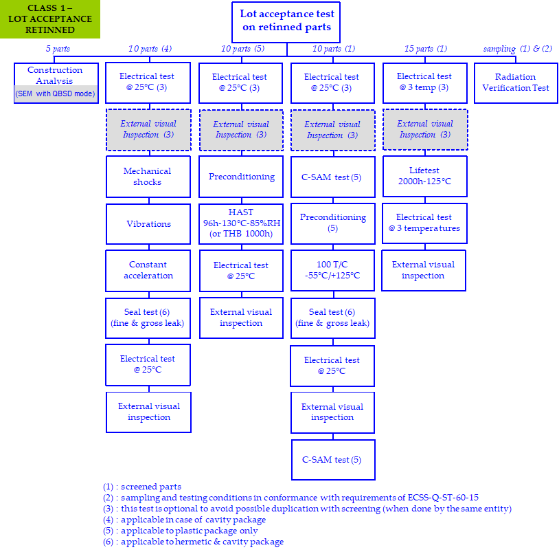 Figure 82: Lot acceptance flow chart for retinned parts – class 1 programmes
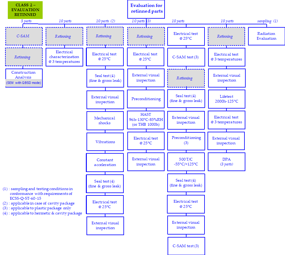
 Figure 83: Evaluation flow chart for retinned parts – class 2 programmes
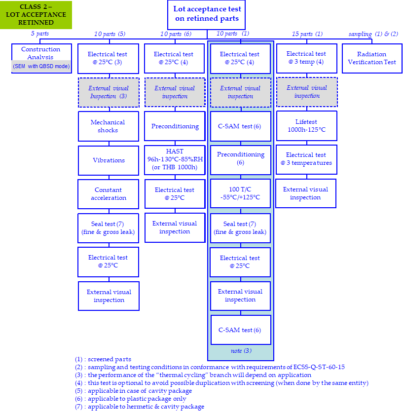 Figure 84: Lot acceptance flow chart for retinned parts – class 2 programmes
 Figure 85: Evaluation flow chart for retinned parts – class 3 programmes
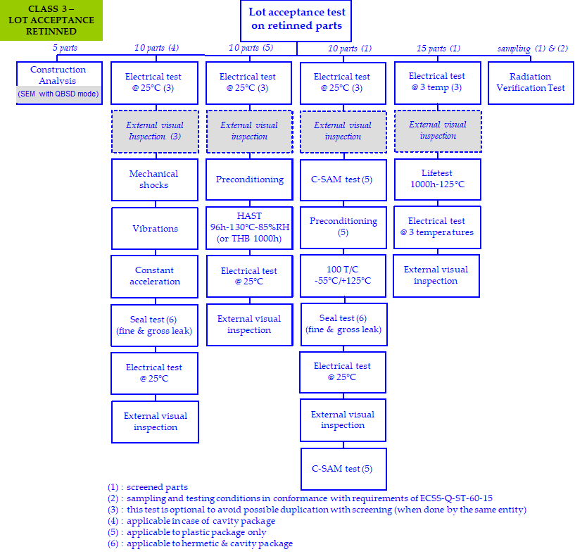 Figure 86: Lot acceptance flow chart for retinned parts – class 3 programmes
Pure tin lead finish – risk analysis
|
9.1 Overview
| ||
|
9.1
|
Pure tin finish has a propensity to generate whiskers. A tin whisker is a conductive crystalline structure of tin growing from tin rich surfaces that can induce failures as:
|
New
|
|
9.2 Requirements
| ||
|
9.2a
|
A pure tin lead finish risk analysis facing whiskers shall include, as a minimum, the following:
|
New
|
|
1. Lead material (e.g. alloy 42, copper)
| ||
|
2. Underlayer material and thickness(e.g. Ni underlayer, silver underlayer)
| ||
|
3. Plating chemistry and thickness(e.g. matte or bright tin, tin thickness)
| ||
|
4. Heat treatment by manufacturer (e.g. 1hour at 150 °C for Cu based lead frame)
| ||
|
5. Procedure (if any) for SnPb dipping of the parts
| ||
|
6. Conformal coating presence and characteristics: material and thickness
| ||
|
7. Design criticality (shorter distances between 2 connections or between a connection and an area at another potential)
| ||
|
8. Supply voltage and current
| ||
|
9. Tin whisker sensitivity results (as per JESD-201 and JESD22- A121A)
| ||
|
10. Mission profile: storage, mission duration, thermal cycling
| ||
|
11. Previous experiences
| ||
ANNEX(normative)Component control plan (CCP) - DRD
|
Annex A.1 DRD Identification
| ||
|
A.1.1 Requirement identification and source document
| ||
|
A.1.1
|
|
Applicable
|
|
A.1.2 Purpose and objective
| ||
|
A.1.2
|
|
Applicable
|
|
A.2 Expected response
| ||
|
A.2.1 Scope and content
| ||
|
A.2.1a
|
|
Applicable
|
|
A.2.2 Special remarks
| ||
|
A.2.2a
|
|
Applicable
|
ANNEX(normative)Declared components list (DCL) - DRD
|
Annex B.1 DRD Identification
| ||
|
B.1.1 Requirement identification and source document
| ||
|
B.1.1
|
|
Applicable
|
|
B.1.2 Purpose and objective
| ||
|
B.1.2
|
|
Applicable
|
|
B.2 Expected response
| ||
|
B.2.1 Scope and content
| ||
|
B.2.1a
|
|
Applicable
|
|
B.2.2 Special remarks
| ||
|
B.2.2
|
|
Applicable
|
ANNEX(normative)Internal Supplier’s specification - DRD
|
Annex C.1 DRD Identification |
||
|
C.1.1 Requirement identification and source document |
||
|
C.1.1 |
This DRD is called up from ECSS‐Q‐ST‐60-13 requirements 4.2.3.1.l and 5.2.3.1.l.
|
Modified |
|
C.1.2 Purpose and objective |
||
|
C.1.2 |
The purpose of the Internal Supplier’s Specification is to establish the tested parameters, test conditions, acceptance criteria, drift limits for the electrical testing during evaluation, screening and lot acceptance.
|
Modified |
|
C.2 Expected response |
||
|
C.2.1 Scope and content |
||
|
C.2.1a |
The internal supplier’s specification shall include or refer to the following information:
|
Modified |
|
|
1. |
Applicable |
|
|
2. |
Applicable |
|
|
3. |
Applicable |
|
|
4. |
Not applicable |
|
|
5. |
Applicable |
|
|
6. |
Applicable |
|
|
7. |
Not applicable |
|
|
8. |
Not applicable |
|
|
9. |
Applicable |
|
|
10. |
Not applicable |
|
|
11. |
Not applicable |
|
|
12. |
Not applicable |
|
|
13. |
Not applicable |
|
|
14. |
Not applicable |
|
|
15. |
Not applicable |
|
|
16. |
Not applicable |
|
|
17. |
Not applicable |
|
C.2.2 Special remarks |
||
|
C.2.2 |
|
Applicable |
ANNEX(normative)Parts approval document - DRD
|
Annex D.1 DRD Identification |
||
|
D.1.1 Requirement identification and source document |
||
|
D.1.1 |
|
Not applicable |
|
D.1.2 Purpose and objective |
||
|
D.1.2 |
|
Not applicable |
|
D.2 Expected response |
||
|
D.2.a |
|
Not applicable |
ANNEX(informative)EEE documents delivery per review
|
Annex E (informative) |
||
|
Annex E |
|
Not applicable |
ANNEX(normative)Justification document - DRD
|
Annex F.1 DRD Identification
| ||
|
F.1.1 Requirement identification and source document
| ||
|
F.1.1
|
This DRD is called up from requirements 4.2.4.d, 5.2.4.d and 6.2.4.d.
|
New
|
|
F.1.2 Purpose and objective
| ||
|
F.1.2
|
The JD is a control document the objective of which is to identify the component and to provide information about it , its evaluation and its acceptability w.r.t.:
|
New
|
|
F.2 Expected response
| ||
|
F.2.1 Scope and content
| ||
|
F.2.1.1 General information
| ||
|
F.2.1.1a
|
The JD shall include:
|
New
|
|
|
1. Family/ sub-family
| |
|
2. Part number (commercial designation)
| ||
|
3. Ordering information
| ||
|
4. Functional description (major parameters for the application)
| ||
|
5. Package
| ||
|
6. Manufacturer (country)
| ||
|
7. Temperature range
| ||
|
8. Absolute maximum rating (Tj max, Pd max, Vcc max,…)
| ||
|
9. Procurement specification/ data sheet (revision, date), Application notes & errata sheet
| ||
|
10. Manufacturer screening & other manufacturer test on procured lot
| ||
|
11. Manufacturer parts traceability (trace-code, date-code, assembly plant, wafer fab, diffusion lot)
| ||
|
12. PCN (Service & for selected parts)
| ||
|
13. Obsolescence (Yes/No)
| ||
|
14. Technology (CMOS, bipolar, and if available process name)
| ||
|
15. Life cycle maturity (emerging/maturity/decline)
| ||
|
16. Technologies with less than one year introduction (yes/no)
| ||
|
17. Moulding characteristics (Tg)
| ||
|
18. Moisture sensitivity level
| ||
|
19. Internal pure tin (Yes/No)
| ||
|
20. Lead finish (RoHs)
| ||
|
21. Justification of the need/ Trade off with Hirel and other commercial sources
| ||
|
F.2.1.2 Supporting data
| ||
|
F.2.1.2a
|
The JD shall include:
|
New
|
|
1. Qualification status /Hirel or automotive parts (same technology)
| ||
|
2. OQ/ EFR/ periodic tests
| ||
|
3. Qualification data
| ||
|
4. Other data / experiences (evaluation, alert, radiation, assembly,…)
| ||
|
5. Demonstration of the representativeness of reliability data
| ||
|
6. the supporting data
| ||
|
F.2.1.3 Evaluation plan
| ||
|
F.2.1.3a
|
The JD shall include:
|
New
|
|
1. Evaluation plan with flow diagram
| ||
|
2. Preliminary and final internal supplier’s specification
| ||
|
F.2.1.4 Additional test on flight lot
| ||
|
F.2.1.4a
|
The JD shall include LAT /screening and RVT plan with flow diagram and test conditions and acceptance criteria (including drift calculation).
|
New
|
|
F.2.1.5 Procurement data
| ||
|
F.2.1.5a
|
The JD shall include traceability information (trace-code, date-code, assembly plant, wafer fab, diffusion lot and die revision).
|
New
|
|
F.2.1.6 Approval status
| ||
|
F.2.1.6a
|
The JD shall include the approval status.
|
New
|
|
F.2.1.7 Appendix
| ||
|
F.2.1.7a
|
The JD shall include:
|
New
|
|
1. A copy of the procurement specification / data sheet
| ||
|
2. Traceability information (CoC, PCN)
| ||
|
F.2.2 Special remarks
| ||
|
F.2.2
|
None
|
New
|
ANNEX(informative)Difference between the three classes
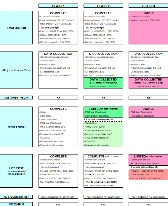
ANNEX(informative)Flow chart for construction analysis and destructive physical analysis
Overview
This annex is a guideline for Construction Analysis (CA) and Destructive Physical Analysis (DPA) sequences to be adapted on a case by case basis for specific products/ technologies as DSM, BGA packages. Construction analysis goals are specifically oriented: quality/ reliability aspects, detection of counterfeit parts, identification of lead finish (RoHs).
Destructive Physical Analysis allow evaluating impact of life test or long duration storage on the parts.
Construction analysis and DPA requirements
Table H-1 gives, for the three classes, the steps to be applied for a construction analysis or a DPA.
Table: Construction analysis and DPA
|
|
Class 1 & 2 programmes
|
Class 3 programmes
| ||||
|
|
Evaluation
|
Procurement
|
Procurement
| |||
|
|
Initial
|
After lifetest
|
Lot acceptance
|
Relifing
|
Lot acceptance
|
Relifing
|
|
Construction analysis (see H.3)
|
X
|
-
|
X
|
-
|
X
|
-
|
|
DPA
|
-
|
X
|
-
|
X
|
-
|
X
|
Construction analysis sequence
Table: Construction analysis sequence
|
TEST
|
SN1
|
SN2
|
SN3
|
SN4
|
SN5
|
PROCEDURE
|
COMMENTS
|
|
External visual inspection
|
X
|
X
|
X
|
X
|
X
|
MIL-STD-750 method 2071
|
MIL specifications are not fitted to visual inspection of PED but can be used as reference (Note 1)
|
|
X-ray inspection
|
X
|
X
|
X
|
X
|
X
|
MIL-STD-750 method 2076
|
-
|
|
C-SAM test
|
X
|
X
|
X
|
X
|
X
|
JEDEC J-STD-020
|
Only applicable to plastic package
|
|
Permanence of marking
|
X
|
X
|
X
|
X
|
X
|
ESCC 24800
|
-
|
|
PIND test
|
X
|
X
|
X
|
X
|
X
|
MIL-STD-750 method 2052
|
-
|
|
Hermeticity (cavity package)
|
|
|
X
|
X
|
X
|
MIL-STD-750 method 1071
|
-
|
|
Residual gas analysis (cavity package)
|
|
|
X
|
X
|
X
|
MIL-STD-750 Method 1018
|
5000 ppm H2O max at
|
|
Lead finish analysis and pure tin identification
|
X
|
X
|
|
|
|
Energy Dispersive X-ray analysis (EDX), Xray fluorescence, Microfluorescence, Differential Scanning Calorimeter (DSC)
|
Analysis to identify lead finish
|
|
Solderability
|
X
|
X
|
|
|
|
MIL-STD-750 method 2026
|
-
|
|
Terminal strength
|
X
|
X
|
|
|
|
MIL-STD-750 Method 2036
|
-
|
|
Delidding
|
X
|
X
|
X
|
X
|
|
-
|
-
|
|
Internal visual inspection
|
X
|
X
|
X
|
X
|
|
ESCC 2045000
|
The die revision shall be identified and recorded
|
|
SEM inspection
|
X
|
X
|
|
|
|
MIL-STD-750 method 2077
|
To verify the quality of wire bonding, glassivation integrity, die interconnect metallization
|
|
Bond strength
|
X
|
X
|
X
|
|
|
MIL-STD-750 method 2037
|
-
|
|
Bond shear (for ball bonding)
|
X
|
X
|
X
|
|
|
JEDEC JASD22-B116
|
-
|
|
Glassivation integrity
|
|
X
|
X
|
X
|
|
MIL-STD-883 method 2021
|
Make sure that the chemical etchant is suitable for the metallization
|
|
Die shear test
|
X
|
X
|
X
|
|
|
MIL-STD-750 method 2017
|
-
|
|
Package level
|
|
|
|
|
X
|
Micro-sectioning of leads shall be performed to assess presence and characteristics of the under-layer
|
Including die micro-sectioning
|
|
Visual, SEM and material analysis
|
|
|
|
|
X
|
-
|
-
|
|
Note 1: In addition to MIL specification criteria, inspect for any evidence of:
| |||||||
Destructive physical analysis sequence
Table: Destructive physical analysis sequence
|
TEST
|
SN1
|
SN2
|
SN3
|
PROCEDURE
|
COMMENTS
|
|
External visual inspection
|
X
|
X
|
X
|
MIL-STD-750 method 2071
|
MIL specifications are not fitted to visual inspection of PED but can be used as reference (Note 1 of section H.3)
|
|
PIND test
|
X
|
X
|
X
|
MIL-STD-750 method 2052
|
-
|
|
Hermeticity
|
X
|
X
|
X
|
MIL-STD-750 method 1071
|
-
|
|
Solderability
|
X
|
X
|
|
MIL-STD-750 method 2026
|
-
|
|
Delidding
|
X
|
X
|
X
|
-
|
-
|
|
Internal visual inspection
|
X
|
X
|
X
|
ESCC 2045000
|
-
|
|
Bond strength
|
X
|
X
|
X
|
MIL-STD-750 method 2037
|
-
|
|
Bond shear
|
X
|
X
|
X
|
JEDEC JASD22-B116
|
-
|
|
Glassivation integrity
|
|
X
|
X
|
MIL-STD-883 method 2021
|
Make sure that the chemical etchant is suitable for the metallization
|
|
Die shear test
|
X
|
X
|
X
|
MIL-STD-750 method 2017
|
-
|
Bibliography
|
ECSS-S-ST-00
|
ECSS system - Description, implementation and general requirements
|
|
ECSS-Q-ST-70-08
|
Space product assurance - Manual soldering of high-reliability electrical connections
|
|
ECSS-Q-ST-70-38
|
Space product assurance - High-reliability soldering for surface-mount and mixed technology
|