
Space engineering
Multipactor design and test
Foreword
This Standard is one of the series of ECSS Standards intended to be applied together for the management, engineering, product assurance and sustainability in space projects and applications. ECSS is a cooperative effort of the European Space Agency, national space agencies and European industry associations for the purpose of developing and maintaining common standards. Requirements in this Standard are defined in terms of what shall be accomplished, rather than in terms of how to organize and perform the necessary work. This allows existing organizational structures and methods to be applied where they are effective, and for the structures and methods to evolve as necessary without rewriting the standards.
This Standard has been prepared by the ECSS-E-ST-20-01C Working Group, reviewed by the ECSS Executive Secretariat and approved by the ECSS Technical Authority.
Disclaimer
ECSS does not provide any warranty whatsoever, whether expressed, implied, or statutory, including, but not limited to, any warranty of merchantability or fitness for a particular purpose or any warranty that the contents of the item are error-free. In no respect shall ECSS incur any liability for any damages, including, but not limited to, direct, indirect, special, or consequential damages arising out of, resulting from, or in any way connected to the use of this Standard, whether or not based upon warranty, business agreement, tort, or otherwise; whether or not injury was sustained by persons or property or otherwise; and whether or not loss was sustained from, or arose out of, the results of, the item, or any services that may be provided by ECSS.
Published by: ESA Requirements and Standards Office ESTEC, P.O. Box 299, 2200 AG Noordwijk The NetherlandsCopyright: 2020© by the European Space Agency for the members of ECSS ## Change log
|
ECSS-E-20-01A
|
First issue
|
|
ECSS-E-ST-20-01A Rev.1
|
First issue, Revision 1
|
|
ECSS-E-ST-20-01C
|
Second issue
|
Introduction
In the context of increased RF power and equipment or component miniaturization, more and more attention shall be paid to multipactor which is critical for space missions based on satellite telecommunication or navigation payloads, or active microwave instruments for Earth Observation or Science. The multipactor phenomenon is an electron avalanche discharge occurring in high vacuum initiated by primary electrons inside a RF component in presence of a high local RF voltage or electric field.
In order to verify by analysis that a RF equipment or component is multipactor free, accurate EM modelling tools are required. These tools need more and more computation resources to cope with RF equipment or components with complex geometries, advanced manufacturing techniques, new materials and processes, and complex RF signals. The verification by test also requires some up-to-date test facilities, that provide high power amplification, electron seeding techniques, multiple and accurate detection methods, ability to generate complex signals, and the ability to reproduce the space representative environment conditions.
This standard is an update of previous version of ECSS-E-20-01A Rev.1, that includes the state-of-art of new verification approaches, and associated margins.
Scope
This standard defines the requirements and recommendations for the design and test of RF components and equipment to achieve acceptable performance with respect to multipactor-free operation in service in space. The standard includes:
verification planning requirements,
definition of a route to conform to the requirements,
design and test margin requirements,
design and test requirements, and
informative annexes that provide guidelines on the design and test processes.
This standard is intended to result in the effective design and verification of the multipactor performance of the equipment and consequently in a high confidence in achieving successful product operation.
This standard covers multipactor events occurring in all classes of RF satellite components and equipment at all frequency bands of interest in high vacuum conditions (pressure lower than 10-5 hPa). Operation in single carrier CW and pulse modulated mode are included, as well as unmodulated multi-carrier operations. A detailed clause on secondary emission yield is also included.
This standard does not include breakdown processes caused by collisional processes, such as plasma formation.
This standard is applicable to all space missions.
This standard may be tailored for the specific characteristic and constrains of a space project in conformance with ECSS-S-ST-00.
Normative references
The following normative documents contain provisions which, through reference in this text, constitute provisions of this ECSS Standard. For dated references, subsequent amendments to, or revision of any of these publications do not apply. However, parties to agreements based on this ECSS Standard are encouraged to investigate the possibility of applying the more recent editions of the normative documents indicated below. For undated references, the latest edition of the publication referred to applies.
|
ECSS-S-ST-00-01
|
ECSS system – Glossary of terms
|
|
ECSS-E-ST-10-02
|
Space engineering – Verification
|
|
ECSS-E-ST-10-03
|
Space engineering – Testing
|
|
ECSS-Q-ST-20
|
Space product assurance – Quality assurance
|
|
ECSS-Q-ST-20-08
|
Space product assurance – Storage, handling and transportation of spacecraft hardware
|
|
ECSS-Q-ST-70-01
|
Space product assurance – Cleanliness and contamination control
|
|
ECSS-Q-ST-70-02
|
Space product assurance – Thermal vacuum outgassing test for the screening of space materials
|
|
ESCC-20600
|
Preservation, packaging and despatch of ESCC component
|
|
ISO 14644–1:2015
|
Cleanrooms and associated controlled environments – Part 1: Classification of air cleanliness by particle concentration
|
Terms, definitions and abbreviated terms
Terms and definitions from other standards
For the purpose of this standard, the terms and definitions from ECSS-S-ST-00-01 apply, in particular the following terms:
acceptance
assembly
bakeout
batch
component
development
equipment
integration
uncertainty
validation
verification
For the purpose of this standard, the terms and definitions from ECSS-E-ST-10-02 apply, in particular the following terms:
acceptance stage
analysis
inspection
model philosophy
qualification stage
review of design
test
verification level
For the purpose of this standard, the terms and definitions from ECSS-E-ST-10-03 apply, in particular the following terms:
acceptance margin
qualification margin
For the purpose of this standard, the terms and definitions from ECSS-Q-ST-70-02 apply, in particular the following terms:
outgassing
Terms and definitions specific to the present standard
analysis margin
required margin of the nominal power with respect to the theoretical threshold power resulting from a Multipactor analysis
assembly
process of mechanical mating of hardware after the manufacturing process
backscattered electron
incident electron that was re-emitted from the material surface with or without energy loss.
batch
group of equipment or component produced in a limited amount of time with the same manufacturing tools, that originates from the same manufacturing lot, and followed the same manufacturing processes
This definition is more specific than the one from the ECSS Glossary ECSS-S-ST-00-01.
batch acceptance margin
allowance of the power level above the nominal power over the specified equipment or component lifetime, excluding testing, to be applied to equipment or component of the same batch
critical gap
Vacuum region within a component or equipment, surrounded by surfaces of any material at which the discharge occurs at the lowest input power for a given frequency within the operating frequency band.
Critical gap does not correspond necessarily to the smallest gap.
discharge
<CONTEXT: multipactor testing> simultaneous response on two or more independent detection methods
The term "multipactor discharge" is synonymous.
event
<CONTEXT: multipactor testing> short time response on one detection method
ferromagnetic material
substances which have a large, positive susceptibility to an external magnetic field, exhibit a strong attraction to magnetic fields and are able to retain their magnetic properties after the external magnetic field has been removed.
gap voltage
voltage over the critical gap
heritage
status of verification based on previously verified reference component or equipment including all relevant parameters
The relevant parameters are listed in Table 41.
multicarrier average power
sum of the average power of each carrier
where:
Pi is the average power of each individual carrier
N is the number of carriers
minimum inflexion point
frequency times gap distance product, corresponding to multipactor order one, at which there is a change in the slope of the breakdown voltage curve and the breakdown voltage is minimized
Figure 31 is given as example. See for more information the Multipactor handbook ECSS-E-HB-20-01.
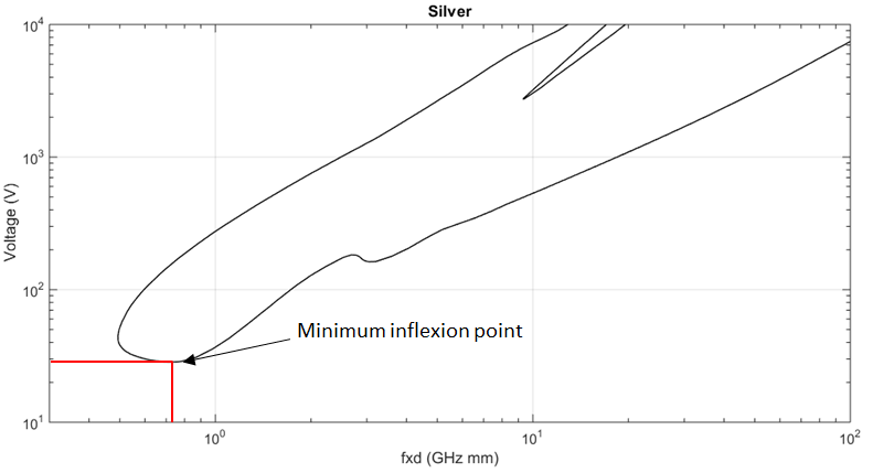 Figure 31: Minimum inflexion point for Silver multipactor chart.
multipactor discharge
see "discharge"
multipactor threshold
<CONTEXT: multipactor testing> lowest power level for which a multipactor discharge has occurred
multicarrier signal
<CONTEXT: multipactor testing> signal composed of a number of independent CW signals at different frequencies
qualification test
test performed on a single unit for establishing that a suitable margin exists in the design and built standard
Such suitable margin is the qualification margin.
RF boundary conditions
impedance matching conditions at all RF ports of the equipment or component
secondary electron emission yield (SEY)
see "total secondary electron emission coefficient"
total secondary electron emission coefficient
ratio of the number of all emitted electrons to the number of incident electrons of defined incident kinetic energy and angle, specific of a material surface under electron irradiation under high vacuum conditions
- 1 The total secondary electron coefficient is the sum of the true secondary electron coefficient and the backscattered electron coefficient.
- 2 The term "secondary electron emission yield" is synonymous.
Abbreviated terms
For the purpose of this Standard, the abbreviated terms from ECSS-S-ST-00-01 and the following apply:
|
Abbreviation
|
Meaning
|
|
AC/DC
|
alternating current/direct current
|
|
BAT
|
batch acceptance test
|
|
BSE
|
back-scattered electron emission
|
|
CDR
|
Critical Design Review
|
|
CFRP
|
carbon-fibre-reinforced plastic
|
|
CW
|
continuous wave
|
|
DC
|
direct current
|
|
DML
|
declared materials list
|
|
DPL
|
declared processes list
|
|
DRD
|
documents requirements definition
|
|
DUT
|
device under test
|
|
EQSR
|
equipment qualification status review
|
|
ECSS
|
European Cooperation for Space Standardization
|
|
EM
|
electromagnetic
|
|
EMC
|
electromagnetic compatibility
|
|
ERS
|
European remote sensing satellite
|
|
ESCC
|
European Space Components Coordination
|
|
FM
|
flight model
|
|
HPA
|
high power amplifier
|
|
IF
|
intermediate frequency
|
|
LNA
|
low noise amplifier
|
|
OMUX
|
output multiplexer
|
|
PDR
|
preliminary design review
|
|
PIC
|
particle in cell
|
|
PID
|
process identification document
|
|
PIMP
|
passive intermodulation product
|
|
RF
|
radio frequency
|
|
SEE
|
secondary electron emission
|
|
SRR
|
system requirements review
|
|
REG
|
regulated electron gun
|
|
RS
|
radioactive source
|
|
SEY
|
secondary emission yield
|
|
TEM
|
transverse electromagnetic mode
|
|
TRB
|
test review board
|
|
TRP
|
temperature reference point
|
|
TRR
|
test readiness review
|
|
TVAC
|
thermal vacuum chamber
|
|
TWTA
|
travelling wave tube amplifier
|
|
UAT
|
unit acceptance test
|
|
UV
|
ultraviolet
|
|
VSWR
|
voltage standing wave ratio
|
|
WG
|
wave guide
|
|
WOCA
|
worst case analysis
|
Nomenclature
The following nomenclature applies throughout this document:
The word “shall” is used in this Standard to express requirements. All the requirements are expressed with the word “shall”.
The word “should” is used in this Standard to express recommendations. All the recommendations are expressed with the word “should”.
It is expected that, during tailoring, recommendations in this document are either converted into requirements or tailored out.
The words “may” and “need not” are used in this Standard to express positive and negative permissions, respectively. All the positive permissions are expressed with the word “may”. All the negative permissions are expressed with the words “need not”.
The word “can” is used in this Standard to express capabilities or possibilities, and therefore, if not accompanied by one of the previous words, it implies descriptive text.
In ECSS “may” and “can” have completely different meanings: “may” is normative (permission), and “can” is descriptive.
The present and past tenses are used in this Standard to express statements of fact, and therefore they imply descriptive text.
Verification
Verification process
ECSS-E-ST-20-01_1450001The process of verification of the equipment with respect to multipactor performance shall demonstrate conformance to the margin requirements defined in clauses 4.6 and 4.7.
ECSS-E-ST-20-01_1450002Verification of the equipment with respect to multipactor shall be performed as part of the overall verification process specified in ECSS-E-ST-10-02, by applying Table 41.
ECSS-E-ST-20-01_1450003Each equipment shall have a dedicated multipactor verification plan as specified in 4.2.2a.
It can involve a combination of design analyses, inspections, development testing, qualification testing, batch acceptance testing and equipment or component acceptance testing.
ECSS-E-ST-20-01_1450004Multipactor performance shall be verified at equipment level.
ECSS-E-ST-20-01_1450005If multipactor performance cannot be verified at equipment level, as specified in 4.1d, then verification may be performed at component level.
ECSS-E-ST-20-01_1450006The process of verification of the component with respect to multipactor performance shall demonstrate conformance to the margin requirements defined in clauses 4.6 and 4.7.
ECSS-E-ST-20-01_1450007Verification of the component with respect to multipactor shall be performed as part of the overall verification process specified in ECSS-E-ST-10-02, by applying Table 41.
ECSS-E-ST-20-01_1450008Each component shall have a dedicated multipactor verification plan as specified in 4.2.2a.
It can involve a combination of design analyses, inspections, development testing, qualification testing, batch acceptance testing and equipment or component acceptance testing.
ECSS-E-ST-20-01_1450009Multipactor performance shall be verified at component level.
ECSS-E-ST-20-01_1450010Table 41: Classification of equipment or component type according to the qualification status and heritage from a multipactor point of view (adapted from Table 5-1 of ECSS-E-ST-10-02)
|
Category
|
Description
|
Comments
|
Verification type
|
|
Am
|
Off the shelf equipment or component without modifications and:
|
|
Review of design
|
|
Bm
|
Off the shelf equipment or component without modifications. However:
|
For this document, modification of project specifications apply to power only
|
Review of design, analysis margin evaluation and if necessary test
|
|
Cm
|
Existing equipment or component with modifications. Modification includes:
|
In case the equipment or component with modification includes a change of materials and processes, the materials and processes subject to change see requirement 9.2a.
|
Review of design, analysis margin evaluation and if necessary test
|
|
Dm
|
Newly designed and developed equipment or component or use of non-already qualified material or process.
|
No analysis and test heritage for the new design or material and process
|
Review of design, analysis margin evaluation and if necessary test
|
Multipactor verification plan
Generation and updating
ECSS-E-ST-20-01_1450011A multipactor verification plan shall be produced at EQSR and, if necessary, updated at the PDR and the CDR at the latest.
ECSS-E-ST-20-01_1450012The multipactor verification plan specified in 4.2.2a shall be kept up-to-date and under configuration control.
The detailed verification plan adopted for any particular project can depend on the qualification status of the equipment and on the model philosophy or production philosophy adopted.
ECSS-E-ST-20-01_1450013The inputs for the multipactor verification plan shall include as a minimum:
- equipment or component requirements specification,
- proposed design,
- equipment or the component qualification status as per Table 41,
- equipment or component type as per Table 42.
Description
ECSS-E-ST-20-01_1450014The multipactor verification plan shall be in conformance with the Verification Plan DRD specified in Annex A of ECSS-E-ST-10-02 plus the following items:
- the verification route as per Figure 41,
- list of the multipactor deliverable documents per review,
- description of tests or analysis to be performed.
The list of Multipactor deliverable documents is given in Table A-1.
ECSS-E-ST-20-01_1450015The multipactor verification plan shall present a coherent sequence of activities that are proposed in order to provide adequate evidence that the requirement specifications for the product are achieved for each delivered item.
ECSS-E-ST-20-01_1450016The multipactor verification plan shall state the criteria for successful completion of each of the verification activities.
Power requirements
General power requirements
Nominal power
ECSS-E-ST-20-01_1450017The nominal power shall be the specified input power for which the equipment or component is designed and verified to be multipactor free.
ECSS-E-ST-20-01_1450018The nominal power shall be the RF power level to which the analysis margin and test margin refers.
ECSS-E-ST-20-01_1450019The nominal power specified at equipment or component level shall exclude RF boundary conditions, neither from payload assembly nor from test bed.
The nominal power for multicarrier signal can be given as power per carrier, or a list of power per carrier.
Increased power P due to payload mismatch
ECSS-E-ST-20-01_1450020The increased power P of the Table 43, Table 44, Table 46 and Table 47 shall be calculated including the mismatch at the RF boundaries of the equipment or the component.
Further details can be found in the Handbook ECSS-E-HB-20-01A.
Failure
ECSS-E-ST-20-01_1450021At payload level, the design and the verification of the equipment or component identified as critical shall include failure modes.
ECSS-E-ST-20-01_1450022As a minimum, the failure modes shall include the following:
- failed equipment
- hot switching
- overdrive scenario
- unexpected thermal variations
- unexpected full or partial RF power reflection
- unexpected increase of input power
ECSS-E-ST-20-01_1450023For multipactor design and verification, the failures modes shall be included only if the equipment recovery is possible.
ECSS-E-ST-20-01_1450024For multipactor design and verification, failure modes that are not recoverable should not be taken.
ECSS-E-ST-20-01_1450025At equipment or component level, the multipactor design and verification shall include the impact of the applicable failure modes identified at payload level.
ECSS-E-ST-20-01_1450026The increased power P shall be determined by taking the change of RF boundary conditions due to the failure mode that yields the worst case among the ones defined in 4.3.1.3c.
Classification of equipment or component type
General classification of equipment or component type
ECSS-E-ST-20-01_1450027The classification of equipment or component types given in Table 41 and in Table 42 shall be used to determine the applicable multipactor margin.
This requirement defines a classification of equipment or component types according to the materials employed in the construction and the geometry and according to the qualification status from a multipactor point of view.
ECSS-E-ST-20-01_1450028In case of doubt when determining the classification of any particular equipment or component, the type with a higher number and a lower level of qualification status shall be used.
ECSS-E-ST-20-01_1450029An equipment consisting of several components shall have the type of the component with the highest number and the lowest level of qualification status.
ECSS-E-ST-20-01_1450030An RF equipment assembly consisting of equipment shall have the type of the equipment with the highest number and the lowest level of qualification status.
ECSS-E-ST-20-01_1450031In case the equipment or component has multiple potential critical gaps of different nature, each one shall be classified as P1 or P2 and follow the verification approach as defined in 4.2.
Examples of potential critical gaps of different nature are metal/metal, metal/dielectric or dielectric/dielectric.
ECSS-E-ST-20-01_1450032In case SEY characterization of materials present in an equipment or component including dielectrics materials is not performed, it shall be considered as P3 equipment or component.
ECSS-E-ST-20-01_1450033Table 42: Classification of equipment or component type according to the material and the geometry
|
Type
|
Characteristics
|
Parameters for equipment or component knowledge
|
|
P1
|
Equipment or component with metal only in the critical gap area. Metal(s) and geometry of equipment or component are known.
|
Minimum parameters: RF path dimensions of the equipment or component Tuning range of the equipment or component (if applicable) SEY of the metal(s) CTE of the material(s) (if applicable) DC EM field (if applicable) |
|
P2(1)
|
Equipment or component with dielectric and possibly metal in the critical gap area. Dielectric material(s), metal(s) and geometry of the equipment or component are known.
|
Minimum parameters:
|
|
P3(1)
|
Any equipment or components not classified as Type P1 or Type P2.
|
If any of the parameters needed for P1 or P2 is unknown, the component or equipment is classified as P3.
|
|
(1) Any P2/P3 component/equipment with a geometry involving 3 media (dielectric, metal and vacuum) and with a sharp edge in the metallic part exhibiting high RF field are prone to generate breakdown phenomena such as “triple-point” discharge which are difficult to analyse and predict. (For more information, see the corresponding clause of the Multipactor handbook ECSS-E-HB-20-01).
| ||
Verification routes
ECSS-E-ST-20-01_1450034Verification shall be accomplished by one of the verification routes shown in Figure 41.
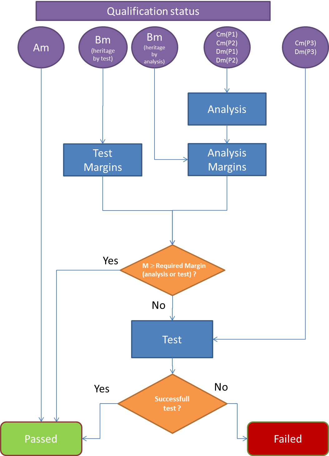 ECSS-E-ST-20-01_1450035Figure 41: Verification routes per component/equipment type and qualification status for multipactor conformance
Single carrier
General
Clause 4.6 states the numerical values of the margins to be used for CW and pulsed systems.
Verification by analysis
Analysis types
ECSS-E-ST-20-01_1450036The Multipactor analysis shall be performed following one of the two possible design analysis levels, L1 and L2, as per clause 5.3.2.
Analysis margins
ECSS-E-ST-20-01_1450037The nominal margins shown in Table 43 and Table 44 for the different contributions and equipment or component types according to the heritage shall be applied.
ECSS-E-ST-20-01_1450038The reduced margins, as indicated in Table 43 and Table 44, may be used if justification is given by the supplier.
The nominal and reduced margins as indicated in Table 43 and Table 44 include modelling error.
ECSS-E-ST-20-01_1450039Table 43: Analysis margins w.r.t. nominal power applicable to P1 and P2 equipment or components with Bm or Cm category verified by analysis
|
Justification type
|
|
L1 analysis
|
L2 analysis
|
L2 analysis
|
L2 analysis
|
|
|
P1 equipment or component
|
P1 equipment or component
|
P1 equipment or component
|
P2 equipment or component(1)
| |
|
Margin type
|
Margin
|
Margin
|
Margin
|
Margin
| |
|
Nominal dimension & ECSS SEY
|
Nominal margin |
6+ΔP |
7+ΔP |
8+ΔP |
N/A |
|
Manufacturing tolerance/thermal stability dimension & ECSS SEY
|
Reduced margin |
5+ΔP |
6+ΔP |
7+ΔP |
N/A |
|
Nominal dimension & WOCA SEY (ageing, temperature) justified by measurement (2)
|
Reduced margin |
4+ΔP |
5+ΔP |
6+ΔP |
8+ΔP(3) |
|
Manufacturing tolerance/thermal stability dimension & WOCA SEY (ageing, temperature) justified by measurement (1) (2)
|
Reduced margin |
3+ΔP |
4+ΔP |
5+ΔP |
7+ΔP(3) |
|
(1) Worst case analysis combining both as-built/thermal stability dimension and real SEY characterized by measurement.
| |||||
ECSS-E-ST-20-01_1450040Table 44: Analysis margins w.r.t. nominal power applicable to P1 and P2 equipment or components with Dm category verified by analysis
|
Justification type
|
|
L1 analysis
|
L2 analysis
| ||
|
|
P1 equipment or component
|
P1 equipment or component
|
P1 equipment or component (other cases)
|
P2 equipment or component(1)
| |
|
Margin type
|
Margin
|
Margin
|
Margin
|
Margin
| |
|
Manufacturing tolerance/thermal stability dimension & WOCA SEY (ageing, temperature) justified by measurement (1) (2) |
Reduced margin |
6+ΔP |
8+ΔP |
10+ΔP |
12 +ΔP(3) |
|
(1) Worst case analysis combining both as-built/thermal stability dimension and real SEY characterized by measurement.
| |||||
Verification by test
Test margins
ECSS-E-ST-20-01_1450041The test margin shall be defined according to the equipment or component type and the heritage.
ECSS-E-ST-20-01_1450042The test margins as shown in Table 45 shall be applied.
Margins shown in Table 45 are those for a payload mismatch of -12 dB. Further discussions regarding the payload mismatch can be found in the Multipactor handbook ECSS-E-HB-20-01.
ECSS-E-ST-20-01_1450043Any deviation from requirement 4.6.3.1b shall be proposed by the supplier and agreed with the customer.
ECSS-E-ST-20-01_1450044Multipactor tests shall be conducted at the temperature range defined in clause 6.3.
ECSS-E-ST-20-01_1450045For P1 equipment or component of type Bm and Cm, the test at ambient temperature may be performed if justifications are provided of the non-impact of temperature over any parameter affecting the breakdown threshold.
Discussions regarding test at ambient can be found in the Multipactor handbook ECSS-E-HB-20-01.
ECSS-E-ST-20-01_1450046Table 45: Test margins w.r.t. nominal power applicable to P1, P2 and P3 equipment or components verified by test
|
Equipment or component type
|
P1
|
P2 or P3
| |
|
Heritage
|
All
|
Bm(1)
|
Bm(2), Cm, Dm
|
|
Qualification Test
|
6
|
6
|
6
|
|
Batch Acceptance Test
|
4
|
4
|
5
|
|
Unit Acceptance Test
|
3
|
3
|
4
|
|
(1) Heritage by test
| |||
Multicarrier
General
Clause 4.7 states the numerical values of the margins to be used for multicarrier systems.
The margins by analysis and test are defined with respect to either the power per carrier of the multicarrier signal, or the multicarrier average power, or the equivalent CW power as specified in 6.4.3.2a.
Verification by analysis
Analysis types
ECSS-E-ST-20-01_1450047The Multipactor analysis shall be performed following one of the two possible levels L1 and L2 as per clause 5.3.2.
Analysis margins
ECSS-E-ST-20-01_1450048The nominal margins shown in Table 46 and Table 47 for the different contributions and equipment or component types according to the heritage shall be applied in addition to the nominal power.
ECSS-E-ST-20-01_1450049The reduced margins as indicated in Table 46 and Table 47 may be used if justification is given by the supplier and agreed by the customer
The nominal and reduced margins as indicated in Table 46 and Table 47 include modelling error.
ECSS-E-ST-20-01_1450050Table 46: Analysis margins applicable to P1 and P2 equipment or components with Bm or Cm category verified by analysis
|
Justification type
|
|
L1 analysis
|
L2 analysis
| ||
|
|
P1 equipment or component
|
P1 equipment or component
|
P1 equipment or component
|
P2 equipment or component(1)
| |
|
Margin type
|
Margin
|
Margin
|
Margin
|
Margin
| |
|
Nominal dimension & ECSS SEY (3)
|
Nominal Margin
|
6+ΔP
|
7+ΔP
|
8+ΔP
|
N/A
|
|
Manufacturing tolerance/thermal stability dimension & ECSS SEY (3)
|
Reduced Margin
|
5+ΔP
|
6+ΔP
|
7+ΔP
|
N/A
|
|
Nominal dimension & WOCA SEY (ageing, temperature) justified by measurement (2)
|
Reduced Margin
|
4+ΔP
|
5+ΔP
|
6+ΔP
|
8+ΔP(3)
|
|
Manufacturing tolerance/thermal stability dimension & WOCA SEY (ageing, temperature) justified by measurement(1) (2)
|
Reduced Margin
|
3+ΔP
|
4+ΔP
|
5+ΔP
|
7+ΔP(3)
|
|
(1) Worst case analysis combining both as-built/thermal stability dimension and real SEY characterized by measurement.
| |||||
ECSS-E-ST-20-01_1450051Table 47: Analysis margins applicable to P1 and P2 equipment or components with Dm category verified by analysis
|
Justification type
|
|
L1 analysis
|
L2 analysis
| ||
|
|
P1 equipment or component
|
P1 equipment or component
|
P1 equipment or component
|
P2 equipment or component(1)
| |
|
Margin type
|
Margin
|
Margin
|
Margin
|
Margin
| |
|
Manufacturing tolerance/thermal stability dimension & WOCA SEY (ageing, temperature) justified by measurement(1) (2)
|
Reduced Margin
|
6+ΔP
|
8+ΔP
|
10+ΔP
|
12+ΔP(3)
|
|
(1) Worst case analysis combining both as-built/thermal stability dimension and real SEY characterized by measurement.
| |||||
Verification by test
Test margins
ECSS-E-ST-20-01_1450052The test margin shall be defined according to the equipment or component type and the heritage.
ECSS-E-ST-20-01_1450053The test margins as shown in Table 48 shall be applied for test performed in single carrier with an equivalent single carrier CW power determined in 6.4.3.2.
- 1 Margins shown in Table 48 are those for a payload mismatch of -12 dB.
- 2 If a single carrier test is not possible, see requirement 6.4.3.1b.
ECSS-E-ST-20-01_1450054Any deviation from Table 48 shall be proposed by the supplier and agreed with the customer.
ECSS-E-ST-20-01_1450055Multipactor tests shall be conducted at the temperature range defined in the clause 6.3.
ECSS-E-ST-20-01_1450056For P1 equipment or component of type B and C, the test at ambient temperature may be performed if justifications are provided of the non-impact of temperature over any parameter affecting the breakdown threshold.
Discussions regarding test at ambient can be found in the Multipactor handbook ECSS-E-HB-20-01.
ECSS-E-ST-20-01_1450057Table 48: Test margins w.r.t. nominal power applicable to P1, P2 and P3 equipment or components verified by test
|
Equipment or component type
|
P1
|
P2 or P3
| |
|
Heritage
|
All
|
Bm(1)
|
Bm(2), Cm, Dm
|
|
Qualification Test
|
6
|
6
|
6
|
|
Batch Acceptance Test
|
4
|
4
|
5
|
|
Unit Acceptance Test
|
3
|
3
|
4
|
|
(1) Heritage by test
| |||
Design analysis
Overview
Clause 5 defines the minimum requirements for performing a satisfactory design analysis with respect to multipactor. These requirements are applicable for all cases where the chosen route to conformance includes analysis. Implementation of such an analysis can vary from sophisticated three-dimensional multipactor simulations to a much simpler estimation process. The analysis represents the application under the specified conditions.
Field analysis
ECSS-E-ST-20-01_1450058An analysis of the electromagnetic fields within the complete equipment or component shall be performed before establishing the worst case multipactor threshold under the specified conditions.
- 1 Multipactor analysis is performed with a proper understanding of the electric fields within the whole equipment or component.
- 2 Specified conditions include parameters such as operational frequency bandwidth, temperature extremes, mismatch conditions, which are applicable to the equipment or component.
- 3 Field analysis without electron tracking solver and surface modelling is used in L1 analysis as described in 5.3.2.2.
- 4 Field analysis with electron tracking solver and surface modelling is used in L2 analysis described in 5.3.2.3.
ECSS-E-ST-20-01_1450059The analysis shall be accomplished by using one of the following methods: - RF EM software,
- estimations from the appropriate use of equivalent circuit models,
- analytical solution of canonical geometries.
ECSS-E-ST-20-01_1450060All regions shall be analyzed to identify the multipactor critical gap.
ECSS-E-ST-20-01_1450061If ferrite materials are present in the equipment or component the following two analyses shall be performed: - an EM field analysis based on the knowledge of the magnetic properties of such ferrite materials, and
- a multipactor analysis including the DC magnetic field applied to the ferrite.
DC magnetic fields applied to ferrite equipment or components include permanent magnets and coils.
Multipactor design analysis
Frequency selection
ECSS-E-ST-20-01_1450062The Multipactor design analysis shall be performed at the frequency within the full bandwidth, at which the EM fields yield the lowest breakdown power.
ECSS-E-ST-20-01_1450063For multicarrier analysis, the carrier frequencies of each of the specified channels shall be used.
Carrier frequency is chosen for multicarrier analysis in order to obtain representative signal envelope characteristics.
Design analysis levels
General design analysis requirements
ECSS-E-ST-20-01_1450064Design analysis shall be applied to equipment or components P1 and P2, according to clause 4.6.2 for single carrier and clause 4.7.2 for multicarrier.
ECSS-E-ST-20-01_1450065The level of analysis shall be selected and performed according to Table 43 and Table 44 for single carrier analysis and to Table 46 and Table 47 for multi-carrier analysis.
ECSS-E-ST-20-01_1450066Depending on the design analysis level, margin shall be adequately applied according to clause 4.6.2.2 or 4.7.2.2.
Analysis level 1 (L1)
General requirements for analysist level 1 (L1)
ECSS-E-ST-20-01_1450067Analysis level 1 shall be applied on equipment or components of type P1.
Criteria for geometry and material
ECSS-E-ST-20-01_1450068The critical gap shall be similar to a parallel surface or coaxial geometry, and the electron trajectory is only possible between two-surfaces.
ECSS-E-ST-20-01_1450069The material, in terms of SEY, shall be selected according to criteria specified in clause 5.3.3.3
ECSS-E-ST-20-01_1450070In case the analysis includes fringing field effect for iris-like geometries, then analyses may be modified based on relevant heritage or studies on such effect if agreed between the supplier and customer on the degree of similarity of the proposed studies.
Fringing field effect can increase the multipactor threshold power level (see respective clause in the Multipactor handbook ECSS-E-HB-20-01).
Analysis methodology for single-carrier case
ECSS-E-ST-20-01_1450071The analysis level 1 with single-carrier signals shall consist of the following steps:
- Computation of the voltage inside the critical region, Vgap, through analytical formula or an electromagnetic software, for a given input power Pin, using the definition of the voltage to power ratio as
- Computation of the multipactor threshold at the corresponding frequency gap distance product, by either:
- using one of the dedicated charts for the list of ECSS materials of clause 5.3.3.4, or
- using a multipactor theory or numerical method for parallel surfaces or coaxial geometry.
- Computation of input power corresponding to the Multipactor threshold voltage computed in point b as
The voltage to power ratio of item 1 is equivalent to the voltage magnification factor defined in the handbook.
ECSS-E-ST-20-01_1450072The customer and supplier shall agree on the method to follow regarding requirement 5.3.2.2.3a.2.
ECSS-E-ST-20-01_1450073Different analysis methodologies may be used in agreement with the customer.
ECSS-E-ST-20-01_1450074The resulting threshold shall be compared with the nominal power increased with the dedicated margin of Table 43 and Table 44.
Analysis methodology for multi-carrier case
ECSS-E-ST-20-01_1450075The analysis level 1with multi-carrier signals shall consist of the following steps:
- Computation of the voltage inside the critical region, Vgap, through analytical formula or an electromagnetic software, for a given input power Pin, giving the EM fields solved for a frequency equal to the mean frequency of all carriers and using the definition of the voltage to power ratio as
This ratio is equivalent to the voltage magnification factor defined in the Multipactor handbook ECSS-E-HB-20-01.
- Compute the breakdown voltage threshold per carrier by either:
- Using the pulsed model approximation in combination with single-carrier analysis.
- Using the envelope sweep approach in combination with a full multicarrier multipactor theory or numerical method for L1, to find the worst-case pulse width that leads to the minimum breakdown power.
ECSS-E-ST-20-01_1450076The pulsed model approximation, specified in 5.3.2.2.4a.2(a), shall consist of the following steps:
- Approximate the multicarrier signal by a pulsed signal, consisting of an on-off rectangular signal, with a frequency of the signal equal to the mean frequency of all carriers, and a period equal to that of the envelope of the multicarrier signal.
- Select the single carrier multipactor theory employed in item 3 in agreement with the customer that allows for analytically computing the electron growth during the "on" interval, and electron absorption during the "off" interval.
- Compute the electron growth during a period by employing the theory selected in item 2.
- Select the worst-case as the combination of the duration and amplitude of the pulse, that produces a discharge with the lowest voltage per carrier, by:
- Using the long-term discharge criterion, where the number of produced electrons is higher than the number of absorbed electrons during a period of the multicarrier signal.
- Determining the computation of the voltage per carrier, given the amplitude of the pulse, by the use of a multicarrier envelope fitting function.
Specific analytical formulas, methodology and different envelope fitting functions are given in the Multipactor handbook ECSS-E-HB-20-01.
ECSS-E-ST-20-01_1450077The envelope sweep, specified in 5.3.2.2.4a.2(b), shall consist of the computation of the Multipactor threshold voltage per carrier given by a full-multicarrier multipactor theory or numerical method for parallel plates, as follows:.
- Selection of M different time intervals of duration i, i varying from 1 to M, in order to fully cover the duration range between 0 and T, where T is the multi-carrier envelop period by ensuring that the number of time intervals is large enough for the convergence.
- Optimization of the carrier phases for each value of i in order to maximize the minimum value of the envelope voltage amplitude during the respective time interval of duration i.
- Computation of the Multipactor voltage threshold for each phase scenario resulting from step 2, considering a long-term discharge, where the number of produced electrons is higher than the number of absorbed electrons during a period of the multicarrier signal.
- Selection of the minimum Multipactor voltage threshold.
A full-multicarrier theory is able to compute the multipactor dynamics (electron growth in time) for an arbitrary combination of frequencies, amplitudes and phases with no simplification of the signal.
ECSS-E-ST-20-01_1450078The customer and supplier shall agree on the method for the computation of the multipactor threshold voltage, specified in 5.3.2.2.4c.
ECSS-E-ST-20-01_1450079The input power corresponding to the Multipactor threshold voltage computed in 5.3.2.2.4a.2 shall be computed as
ECSS-E-ST-20-01_1450080Different analysis methodologies may be used in agreement with the customer.
ECSS-E-ST-20-01_1450081The resulting threshold shall be compared with the nominal power increased with the dedicated margin of Table 46 and Table 47.
Analysis level 2 (L2)
General requirements for analysist level 2 (L2)
ECSS-E-ST-20-01_1450082Analysis level 2 shall be applied on equipment or components of type P1 or P2.
Criteria for geometry and material
ECSS-E-ST-20-01_1450083The secondary emission properties used shall be selected according to criteria specified in clause 5.3.3.3.
ECSS-E-ST-20-01_1450084According to the geometry of the critical gap, any equipment or component type 1 (P1) which cannot be analysed through L1, shall be analysed through L2.
This includes for instance multiple electron trajectories, complex 3D structures where the critical cannot be locally approximated by a parallel plate or coaxial cases.
ECSS-E-ST-20-01_1450085Type 2 equipment or components (P2) shall be analysed through L2, considering the DC electric field created by the dielectric charging in order to determine the worst case of Multipactor threshold.
Analysis methodology for single-carrier case
ECSS-E-ST-20-01_1450086The analysis level 2 shall be characterized by the computation of the Multipactor threshold with a 3D coupled RF EM and electron tracking and surface modelling software.
ECSS-E-ST-20-01_1450087A convergence study of the mesh density and of the initial number of electrons shall be performed until the Multipactor threshold is stabilized.
ECSS-E-ST-20-01_1450088The resulting threshold shall be compared with the nominal power increased with the dedicated margin of Table 43 and Table 44.
Analysis methodology for multi-carrier case
ECSS-E-ST-20-01_1450089The analysis L2 with multi-carrier signals shall be done by using the envelope sweep approach to find the worst-case pulse width that leads to the minimum breakdown power in the following sequence:
- Computation of the Multipactor threshold power per carrier given by a 3D coupled RF EM and electron tracking and surface modelling software.
- Comparison of the obtained power threshold per carrier with the nominal power per carrier increased with the dedicated margin of Table 46 and Table 47. ECSS-E-ST-20-01_1450090The computation of the multipactor threshold power per carrier, as specified in 5.3.2.3.4a.1, shall consist of:
- Selection of M different time intervals of duration i, i varying from 1 to M, in order to fully cover the duration range between 0 and T, where T is the multi-carrier envelop period by ensuring that the number of time intervals is large enough for the convergence.
- Optimization of the carrier phases for each value of i in order to maximize the minimum value of the envelope voltage amplitude during the respective time interval of duration i.
- Computation of the Multipactor power threshold for each phase scenario resulting from step 2, considering a long-term discharge, where the number of produced electrons is higher than the number of absorbed electrons during a period of the multicarrier signal.
- Selection of the minimum Multipactor power threshold. ECSS-E-ST-20-01_1450091Different analysis methods may be used in agreement with the customer.
Alternative methods are described in the handbook.
ECSS-E-ST-20-01_1450092A convergence study of the mesh density and of the initial number of electrons shall be performed until the Multipactor threshold is stabilized.
Validation of theory and software
ECSS-E-ST-20-01_1450093For parallel-plate theory and both 3D EM and electron trajectory computation, any technique shall be validated by either:
- demonstrable heritage, or
- multipactor breakdown computation of representative sample and comparison with experimental results or results coming from a validated theory or software.
Examples of representative samples are given in the Multipactor handbook ECSS-E-HB-20-01.
Available data for Multipactor analysis
General
ECSS-E-ST-20-01_1450094The analysis margin strategy to be applied shall depend on the available data for two parameters, dimensions and SEY:
- Dimensional accuracy and stability:
- Nominal values
- Worst case, including manufacturing tolerances and thermal effect.
- SEY available data
- ECSS SEY data
- Measured SEY, including ageing and temperature effect and charging (if applicable)
ECSS-E-ST-20-01_1450095For each case specified in 5.3.3.1a, the dedicated margin of Table 43, Table 44, Table 46 or Table 47 shall be applied depending on the level analysis and the type of equipment or component.
Dimensional accuracy and stability
ECSS-E-ST-20-01_1450096The worst case dimension shall be determined using following steps:
- include the accuracy and stability of the dimensions of the equipment or component, including manufacturing tolerances and the thermal effect.
- study the effect of the thermo-elastic distortion on the qualification temperature range.
- use the smallest dimension of the critical gap, provided that the RF equipment or component remains compliant with the electrical performance specifications.
- evaluate the lowest breakdown power within the whole gap dimensional variation range, if the fxd product is lower than the minimum inflexion point of the curve, and select the gap yielding the lowest breakdown power.
- compute the dimensional variation over the iris length in the presence of short irises, and select the longest iris length as the worst-case for all cases.
ECSS-E-ST-20-01_1450097For the nominal dimension, the analysis shall be performed without including the manufacturing tolerances and the thermal effect.
ECSS-E-ST-20-01_1450098In case tuning elements are present in P1 or P2 equipment or component, the predicted worst and best case threshold power shall be derived by applying the range of the tuning elements.
SEY available data
ECSS-E-ST-20-01_1450099SEY data used in the analysis shall be representative of the material in the critical part of the equipment and come from either measured SEY or ECSS SEY.
ECSS-E-ST-20-01_1450100For measured SEY, the SEY curve shall be the worst case including the ageing, contamination and temperature and charging properties as specified in requirement9.3a.
ECSS-E-ST-20-01_1450101If no ad-hoc SEY measurement data are available, and the material is listed in Table 91, the corresponding material data from this table shall be taken.
ECSS-E-ST-20-01_1450102If no ad-hoc SEY measurement data are available, and the material is not listed in Table 91, no analysis is possible and the equipment or component shall be classified as P3.
ECSS-E-ST-20-01_1450103P1 equipment or components shall be analysed with either measured SEY or ECSS SEY data.
ECSS-E-ST-20-01_1450104P2 equipment or components shall be analysed with measured SEY data.
ECSS-E-ST-20-01_1450105If different materials are present at the critical gap, the material with the worse SEY envelope curve shall be taken for analysis level 1.
ECSS Multipactor charts
ECSS-E-ST-20-01_1450106To compute the threshold level for L1 analysis according to clause 5.3.2.2 the values of Table 51 shall be taken.
The multipactor charts in Figure 51 to Figure 55 are a visual representation of breakdown voltage for each of the metals listed in Table 91.
ECSS-E-ST-20-01_1450107Table 51: Tabulated values of the lowest breakdown voltage threshold boundary of the multipactor charts, computed with the SEY data of Table 91
|
fxd
|
Breakdown Voltage (V)
| |||
|
Aluminium
|
Copper
|
Silver
|
Gold
| |
|
0,43
|
33,8
|
|
|
|
|
0,47
|
28,5
|
36,6
|
|
|
|
0,49
|
27,4
|
33,4
|
|
41,0
|
|
0,50
|
27,0
|
32,5
|
38,3
|
38,1
|
|
0,53
|
26,1
|
30,8
|
33,7
|
34,5
|
|
0,56
|
25,4
|
29,7
|
31,7
|
32,8
|
|
0,59
|
24,7
|
28,8
|
30,4
|
31,6
|
|
0,62
|
24,2
|
28,1
|
29,5
|
30,8
|
|
0,66
|
24,0
|
27,7
|
28,9
|
30,2
|
|
0,70
|
23,8
|
27,4
|
28,5
|
29,8
|
|
0,74
|
24,1
|
27,5
|
28,5
|
29,7
|
|
0,78
|
24,7
|
27,7
|
28,7
|
29,8
|
|
0,82
|
25,9
|
28,7
|
29,7
|
30,6
|
|
0,87
|
27,2
|
29,9
|
30,9
|
31,6
|
|
0,92
|
29,3
|
31,9
|
32,9
|
33,5
|
|
0,97
|
31,5
|
34,0
|
35,2
|
35,7
|
|
1,02
|
34,4
|
37,0
|
38,3
|
38,6
|
|
1,08
|
37,7
|
40,3
|
41,7
|
42,0
|
|
1,14
|
41,6
|
44,4
|
45,9
|
46,0
|
|
1,21
|
46,2
|
49,0
|
50,8
|
50,8
|
|
1,28
|
51,3
|
54,2
|
56,2
|
56,2
|
|
1,35
|
56,9
|
60,3
|
62,5
|
62,4
|
|
1,43
|
63,4
|
67,0
|
69,5
|
69,3
|
|
1,51
|
70,5
|
74,8
|
77,2
|
77,0
|
|
1,59
|
78,4
|
83,3
|
86,0
|
85,8
|
|
1,68
|
86,1
|
91,9
|
95,4
|
95,3
|
|
1,78
|
94,3
|
101,4
|
105,6
|
105,6
|
|
1,88
|
102,0
|
110,8
|
116,0
|
116,0
|
|
1,99
|
110,1
|
120,9
|
126,9
|
127,0
|
|
2,10
|
117,4
|
130,1
|
137,5
|
137,6
|
|
2,22
|
124,8
|
139,7
|
148,5
|
148,7
|
|
2,34
|
130,5
|
148,2
|
159,4
|
159,4
|
|
2,48
|
133,7
|
156,7
|
170,6
|
170,3
|
|
2,62
|
131,8
|
160,2
|
179,7
|
179,2
|
|
2,77
|
128,4
|
154,3
|
182,2
|
181,3
|
|
2,92
|
129,6
|
149,2
|
167,6
|
168,7
|
|
3,09
|
134,0
|
150,6
|
162,4
|
163,6
|
|
3,27
|
139,7
|
155,2
|
165,4
|
166,3
|
|
3,45
|
147,8
|
163,0
|
172,8
|
173,6
|
|
3,65
|
156,6
|
171,7
|
181,4
|
181,8
|
|
3,85
|
167,8
|
183,4
|
193,5
|
193,9
|
|
4,07
|
179,6
|
195,8
|
206,3
|
206,6
|
|
4,30
|
193,1
|
211,2
|
222,9
|
223,2
|
|
4,55
|
207,5
|
227,6
|
240,4
|
240,7
|
|
4,81
|
221,7
|
244,6
|
258,2
|
258,5
|
|
5,08
|
236,5
|
262,5
|
276,9
|
277,2
|
|
5,37
|
249,5
|
277,3
|
292,2
|
292,7
|
|
5,67
|
261,8
|
290,7
|
306,4
|
307,1
|
|
5,99
|
273,1
|
302,9
|
321,1
|
321,8
|
|
6,33
|
284,0
|
314,4
|
336,2
|
336,9
|
|
6,69
|
298,3
|
329,6
|
353,4
|
354,0
|
|
7,07
|
317,5
|
350,3
|
373,3
|
373,9
|
|
7,47
|
337,5
|
372,1
|
394,8
|
395,4
|
|
7,90
|
357,3
|
394,5
|
419,2
|
419,7
|
|
8,34
|
378,3
|
418,0
|
444,8
|
445,3
|
|
8,82
|
399,9
|
441,6
|
469,9
|
470,5
|
|
9,32
|
422,4
|
466,6
|
496,5
|
497,1
|
|
9,85
|
446,2
|
493,1
|
525
|
525
|
|
10,41
|
471,4
|
521
|
554
|
555
|
|
11,00
|
498,9
|
551
|
586
|
587
|
|
11,62
|
528
|
583
|
621
|
621
|
|
12,28
|
559
|
617
|
657
|
657
|
|
12,98
|
592
|
653
|
695
|
695
|
|
13,71
|
626
|
691
|
736
|
736
|
|
14,49
|
662
|
731
|
779
|
779
|
|
15,31
|
700
|
773
|
825
|
825
|
|
16,18
|
742
|
819
|
874
|
873
|
|
17,10
|
786
|
867
|
925
|
924
|
|
18,07
|
832
|
919
|
981
|
980
|
|
19,10
|
881
|
974
|
1039
|
1038
|
|
20,18
|
934
|
1032
|
1102
|
1100
|
|
21,32
|
990
|
1093
|
1168
|
1166
|
|
22,53
|
1050
|
1160
|
1240
|
1236
|
|
23,81
|
1113
|
1229
|
1315
|
1311
|
|
25,16
|
1181
|
1305
|
1397
|
1392
|
|
26,59
|
1254
|
1385
|
1483
|
1478
|
|
28,10
|
1370
|
1512
|
1577
|
1570
|
|
29,69
|
1532
|
1704
|
1677
|
1668
|
|
31,38
|
1682
|
1870
|
1783
|
1773
|
|
33,16
|
1797
|
2000
|
1897
|
1885
|
|
35,04
|
1875
|
2089
|
2019
|
2006
|
|
37,03
|
1885
|
2087
|
2152
|
2136
|
|
39,13
|
1926
|
2129
|
2293
|
2274
|
|
41,35
|
2052
|
2269
|
2448
|
2425
|
|
43,70
|
2186
|
2418
|
2611
|
2585
|
|
46,18
|
2332
|
2581
|
2791
|
2761
|
|
48,80
|
2486
|
2753
|
2981
|
2946
|
|
51,57
|
2654
|
2941
|
3191
|
3150
|
|
54,49
|
2833
|
3141
|
3414
|
3367
|
|
57,59
|
3026
|
3359
|
3659
|
3604
|
|
60,85
|
3232
|
3593
|
3921
|
3858
|
|
64,31
|
3453
|
3845
|
4206
|
4132
|
|
67,95
|
3690
|
4115
|
4514
|
4430
|
|
71,81
|
3894
|
4383
|
4846
|
4752
|
|
75,88
|
4050
|
4642
|
5208
|
5101
|
|
80,19
|
4283
|
4952
|
5595
|
5474
|
|
84,74
|
4698
|
5368
|
6014
|
5878
|
|
89,55
|
5117
|
5798
|
6458
|
6306
|
|
94,63
|
5440
|
6200
|
6936
|
6767
|
|
100,00
|
5782
|
6624
|
7440
|
7254
|
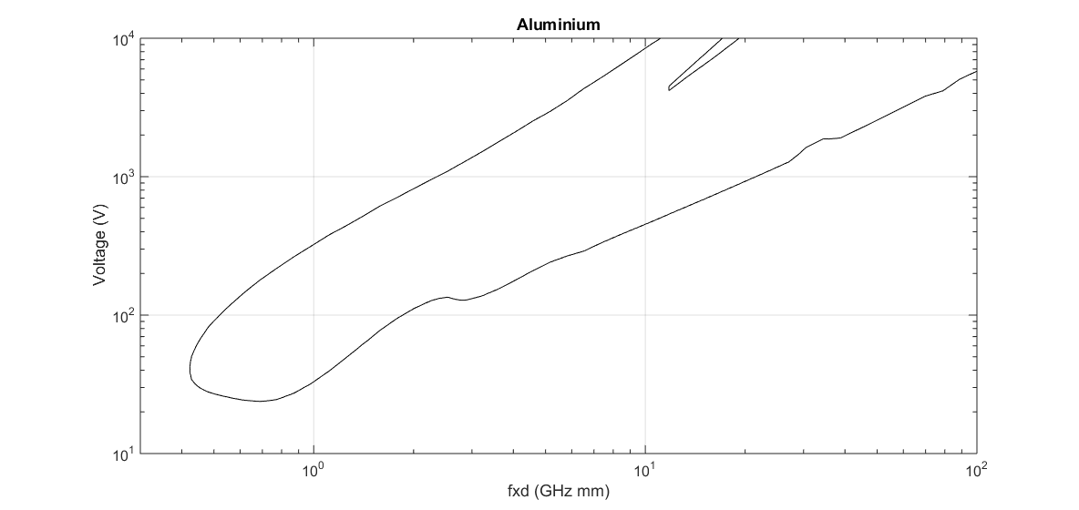 Figure 51: Multipactor chart for standard Aluminium obtained with parameters from Table 91
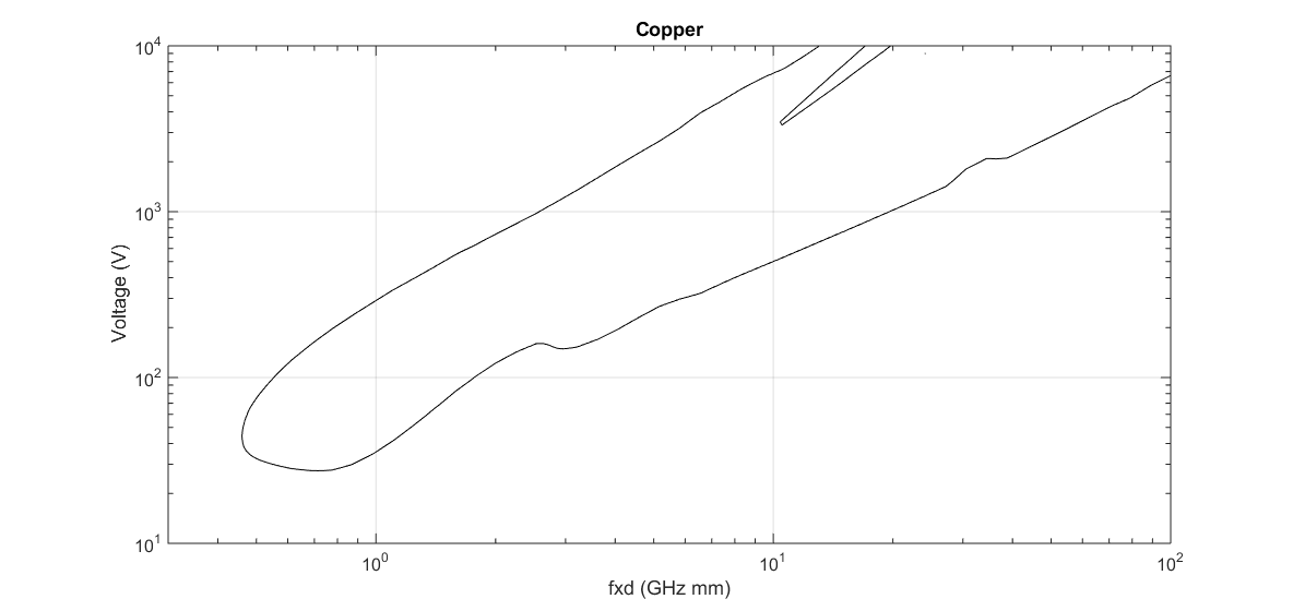 Figure 52: Multipactor chart for standard Copper obtained with parameters from Table 91
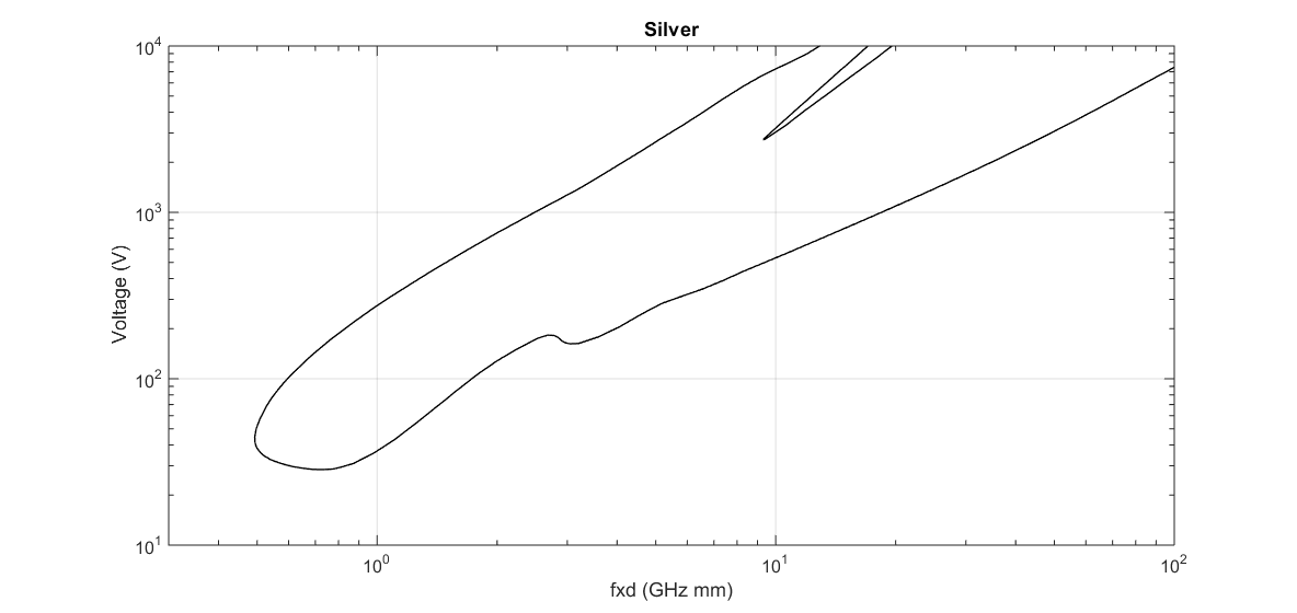 Figure 53: Multipactor chart for standard Silver obtained with parameters from Table 91
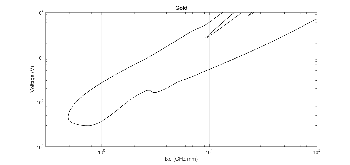 Figure 54: Multipactor chart for standard Gold obtained with parameters from Table 91
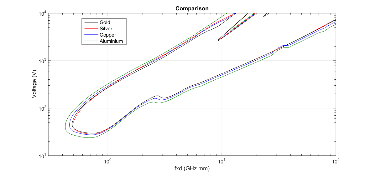 Figure 55: Comparison of Multipactor charts for all standard materials obtained with parameters from Table 91
Multipactor - Test conditions
Cleanliness
ECSS-E-ST-20-01_1450108Airborne particulate cleanliness class 8 as per ISO 14644-1 or better conditions, shall be maintained throughout the equipment or component assembly, test, delivery and post-delivery phases.
ECSS-E-ST-20-01_1450109In addition, standard clean room practices for handling flight equipment and for general prevention of contamination, agreed with the customer, shall be strictly applied.
ECSS-E-ST-20-01_1450110Protective covers to prevent the ingress of contaminants shall be used.
ECSS-E-ST-20-01_1450111If surfaces are vulnerable to contamination the surface molecular and particle contamination shall be monitored in accordance with clause 5.4.2 of ECSS-Q-ST-70-01.
ECSS-E-ST-20-01_1450112If the contamination monitoring, specified in 6.1d, shows that the specified levels are exceeded, the surface shall be cleaned according to the requirement of clause 5.4.1 of ECSS-Q-ST-70-01.
Contamination is any unwanted molecular or particulate matter, including microbiological matter, on the surface or in the environment of interest that can affect or degrade the relevant performance or life time.
Pressure
ECSS-E-ST-20-01_1450113A vacuum bake-out shall be performed on all equipment or components before multipactor testing.
ECSS-E-ST-20-01_1450114The combination of maximum temperature and time duration used for the bake-out shall be equivalent to that which is present in the operational environment of the spacecraft payload.
The above requirement allows for accelerated bake-out at higher temperatures over relatively short time periods, where the maximum allowable temperature has been approved by the customer. Refer to the ECSS Multipactor handbook ECSS-E-HB-20-01, for further details on determining equivalence of outgassing conditions.
ECSS-E-ST-20-01_1450115Multipactor testing shall be performed at pressures below 1,0 × 10⁻⁵ hPa in the thermal vacuum chamber.
A lower pressure inside the critical regions of the equipment or component can be achieved by providing an adequate combination of:
- pressure in the vacuum chamber,
- venting design for the equipment or component, and
- time for moisture to outgas from the equipment or component.
ECSS-E-ST-20-01_1450116The pressure in the thermal vacuum chamber shall be monitored continuously during the test.
ECSS-E-ST-20-01_1450117If, as a consequence of the monitoring specified in 6.2d, any unexpected pressure increases are detected, these events shall be noted in the test report and correlated against the readings of the multipactor detection methods.
Temperature
ECSS-E-ST-20-01_1450118Multipactor tests shall be performed at the temperature extremes defined for the DUT at the critical gap.
Thermal analysis results can be used to ensure that the required temperature is met in the critical region (including thermal stability)
ECSS-E-ST-20-01_1450119For P1 equipment or component of type Bm and Cm, test at ambient temperature may be performed if justifications are provided and agreed with the customer, of the non-impact of temperature over any parameter affecting the breakdown threshold.
Discussions regarding test at ambient can be found in the corresponding clause ECSS Multipactor handbook ECSS-E-HB-20-01.
ECSS-E-ST-20-01_1450120A equipment or component tested at extreme temperatures as described in 6.3a shall be tested at the hot and cold extremes with reference to the relevant temperature range:
- For qualification tests, the qualification temperature range for EQM and QM.
- For batch- and unit tests, the acceptance temperature range for PFM and FM.
ECSS-E-ST-20-01_1450121In the case that a reduced temperature range is agreed with the customer, the new temperature limits may be used for the tests specified in 6.3a.
ECSS-E-ST-20-01_1450122As a minimum the Temperature Reference Point (TRP) of the DUT shall be monitored during the complete test duration, for ambient tests as well as for tests performed at extreme temperatures.
ECSS-E-ST-20-01_1450123A maximum acceptable temperature of the TRP shall be specified by the customer.
ECSS-E-ST-20-01_1450124The thermal dissipation in the DUT caused by the selected multipactor test signal profile, CW, pulsed or multi-carrier, shall be analysed.
ECSS-E-ST-20-01_1450125The maximum average power applied during multipactor testing shall be no greater than the value used in the thermal analysis.
Signal characteristics
Applicable bandwidth
ECSS-E-ST-20-01_1450126The applicable bandwidth for a multipactor test shall be defined as follows:
- For a qualification test, the applicable bandwidth is the full bandwidth for which the equipment or component is designed.
- For a batch- or unit test, the applicable bandwidth is the bandwidth, which is applicable for the current project or application.
Single-frequency test case
ECSS-E-ST-20-01_1450127The test frequency shall be determined in accordance with 5.3.1.
Multi-frequency test case
General
ECSS-E-ST-20-01_1450128A test with a single carrier, applying an equivalent power as specified in clause 6.4.3.2. shall be performed.
ECSS-E-ST-20-01_1450129If a single carrier test is not possible, a test with a multi-carrier signal, subjected to a frequency multiplex with CW carriers located in accordance with the operational frequency plan and with free-running phase per carrier may be performed under the condition that the test margins and test conditions, including the duration, are agreed between supplier and customer.
ECSS-E-ST-20-01_1450130If the two tests specified in 6.4.3.1a and 6.4.3.1b are not possible a test with a reduced number of carriers applying an equivalent power as specified in clause 6.4.3.3 may be performed with free-running phase per carrier under the condition that the test margins and test conditions, including the duration are agreed between supplier and customer.
Multi-frequency test with a single carrier applying an equivalent power
ECSS-E-ST-20-01_1450131For the multi-carrier tests performed with an equivalent CW single carrier, test margins of Table 45 shall be applied.
ECSS-E-ST-20-01_1450132A single carrier equivalent power for a test as described under 6.4.3.2a above shall be defined as follows:
- perform a single carrier analysis at the average frequency of the multicarrier signal in accordance with clause 5.3.2.1 and 5.3.2.2.3 for L1 or 5.3.2.3.3 for L2 where the threshold power in Watts is denoted Pth,sc,
- perform a multicarrier analysis on the same analysis level, L1 or L2,as the single carrier analysis specified in 1 above,
- calculate the average threshold power in Watts, sum of all carrier power values, found in the multicarrier analysis, denoted Pth,mc with m the number of carriers, using for both, the single carrier and the multi carrier analysis, identical design charts, identical electromagnetic computational model as well as identical material parameters and geometry definitions,
- calculate the equivalent power for a single carrier test of a multicarrier device using following formula: Peq,sc = P0 · Pth,sc/Pth,mc, where P0 is the nominal multicarrier average power in Watts, sum of all carrier power values, of the input signal,
- verify that the computed equivalent power from step 4 for a single carrier test of a multicarrier device is always bounded by P0 ≤ Peq,sc ≤ NP0, where N is the number or of carriers,
- The single carrier test frequency is the average frequency of the multi-carrier signal as for the single carrier analysis in step 1.
- 1 If the single carrier analysis was an L1 analysis performed according to clause 5.3.2.1 and 5.3.2.2.3, the multicarrier analysis is performed according to clauses 5.3.2.1 and 5.3.2.2.4.
- 2 If the single carrier analysis was an L2 analysis performed according to clauses 5.3.2.1 and 5.3.2.3.3, the multicarrier analysis is performed according to clauses 5.3.2.1 and 5.3.2.3.4.
Multi-frequency test with reduced number of carriers applying an equivalent power
ECSS-E-ST-20-01_1450133A reduced number of carrier equivalent power for a test as described under 6.4.3.2 shall be defined as follows:
- Select the reduced frequency plan in order to have the same average frequency and the same voltage envelope period as the original multi-carrier signal.
- If item 1 is not possible due to test facility constraints, a different frequency plan with a reduced number of carriers can be used in agreement with the customer.
- Perform a multicarrier analysis for both frequency plans, with reduced number of carrier or not, with the same analysis level in accordance with clause 5.3.2.2.4 for L1 and clause 5.3.2.3.4 for L2,
- calculate the threshold power found in the multicarrier analysis, denoted Pth,mc,n, with n being the reduced number of carriers compared to Pth,mc,m, with m being the original number of carriers, using for both cases identical simulation models.,
- calculate the equivalent power for a multicarrier test with a reduced number of carriers using following formula: Equation Where:
Equation P0,mc,n is the nominal power of the input signal for n carriers
Equation P0,mc,m is the nominal power of the input signal for m carriers
Equation P0,mc,n is the nominal power of the input signal for n carriers
Pulsed testing
ECSS-E-ST-20-01_1450134Pulsed testing may be applied in the cases of equipment or components operating in CW mode.
For equipment or components operating in CW mode, pulsed testing is an alternative commonly used to avoid thermal effects, which could generate temperature levels in the unit beyond the maximum allowed limits. For this reason, the duty cycle is proportionally and gradually reduced to keep the average CW level constant as the peak power is increased towards the required test margin. This is achieved by varying the PRF between each power step to allow the mean power to be maintained, such that it does not exceed the maximum permitted level.
ECSS-E-ST-20-01_1450135The pulse width shall be equal or greater than 20 microseconds with a duty cycle of at least 2% to ensure sufficient electron seeding as per 6.5.3.
Shorter pulsed width and lower duty cycles can be used if they are representative of the operational signal characteristics.
ECSS-E-ST-20-01_1450136The pulse duration used to test equipment or component that experience pulsed excitation in service shall be between 20 microseconds and the longest pulse duration that the equipment or component experiences in service.
ECSS-E-ST-20-01_1450137The suitability of the proposed pulse width and duty cycle as well as compliance with the definition of sensitivity and rise time for the detection methods as described in 7.3.2 and 7.3.3 shall be demonstrated through the reference sample multipactor test according to 8.3b.2.
Electron seeding
General
ECSS-E-ST-20-01_1450138If seeding is proven to be inefficient on the real DUT at the critical area, the verification by test may be performed on a dedicated BB or EM unit where the design of outer parts and structures is modified in such a way that the critical gaps can be properly seeded.
Multipactor test in CW operation
ECSS-E-ST-20-01_1450139An electron seed source shall be used for CW Multipactor test.
ECSS-E-ST-20-01_1450140Electron seeding may not be used, if the test site demonstrates according to 8.3b.2, with a known reference sample representative of the DUT with respect to the material, the surface properties, the wall thickness – if applicable to the seeding method – and the gap dimensions that the same multipactor threshold as with electron seeding is achieved.
Multipactor test in pulsed operation
ECSS-E-ST-20-01_1450141An electron seed source shall be used in pulsed testing.
ECSS-E-ST-20-01_1450142In those test cases where electron seeding is ineffective due to restricted access to the critical areas, the test signal shall be in CW mode and validated in accordance with 6.5.2b.
ECSS-E-ST-20-01_1450143If, in a test case as described in 6.5.3b, it is not possible to perform CW test, the pulsed test may be performed using a longer pulse width and higher duty cycle than what is defined in 6.4.4, pending customer approval on a case by case basis.
Multipactor test in multi-carrier operation
ECSS-E-ST-20-01_1450144An electron seed source shall be used in the multi-carrier environment.
ECSS-E-ST-20-01_1450145If the test site demonstrates with a reference sample according to 8.3b.2 that the expected multipactor threshold is achieved, electron seeding may not be used.
Seeding sources
ECSS-E-ST-20-01_1450146Any applied method or technique of electron seeding shall be implemented aiming at the critical gap where multipactor breakdown can occur during the test.
ECSS-E-ST-20-01_1450147If the DUT has more than one critical gap, where a seeding source is required according to 6.5.5a, at least one seeding source shall be used at each critical gap, simultaneously or consecutively.
ECSS-E-ST-20-01_1450148The seeding electrons shall have a direct path to the critical gap where seeding is required.
For a radioactive βsource according to 6.5.5d.4, the direct path requirement is applicable to the secondary low energy electrons.
ECSS-E-ST-20-01_1450149At least one of the following seeding sources shall be used:
- UV light source, which produces electrons by the photoemission mechanism.
- An electron gun, which produces a known beam of electrons where both the energy and flux can be characterised.
- A charged wire probe, which produces electrons by the point discharge mechanism.
- Radioactive βsource, which produces high-energy electrons that, after impacting with metal surfaces or propagation though metallic or dielectric walls, yield a supply of secondary low energy seed electrons.
If a metallic or dielectric wall is too thick, the high-energy electrons will not be able to propagate and the supply of secondary low energy electrons will not be sufficient. Recommendations for wall thickness are provided in the Multipactor handbook ECSS-E-HB-20-01.
Seeding verification
ECSS-E-ST-20-01_1450150It shall be verified during the test facility validation, according to clause 8.3, using the chosen detection methods and a reference sample with a known multipactor threshold, that the seeding method is able to produce a sufficient number of seed electrons in the critical gaps of the DUT.
ECSS-E-ST-20-01_1450151The reference sample shall have a geometry, which allows for a representative path of the seeding electrons compared to the seeding electron path of the DUT.
Further guidelines can be found in the Multipactor handbook ECSS-E-HB-20-01.
Multipactor - Methods of detection
General
This clause defines the minimum requirements for the detection methods used for multipactor testing. Details of such test methods are included in the Multipactor handbook ECSS-E-HB-20-01.
Detection methods
ECSS-E-ST-20-01_1450152The detection methods shall be selected from the following list:
- Global methods:
- Close to carrier noise
- Phase noise
- Harmonic noise
- Phase nulling.
- Pulse envelope detection
- Low-level amplitude modulation of test signal
- Local methods:
- Optical
- Electron probe
- Other detection methods, providing demonstration of its effectiveness and validation as per clause 7.3. ECSS-E-ST-20-01_1450153At least two detection methods shall be present in the test configuration and at least one of them be a global method.
It is good practise to use both local and global detection methods simultaneously.
Detection method parameters
Verification
ECSS-E-ST-20-01_1450154The testing entity shall verify that the detection methods selected are able to detect multipactor events.
ECSS-E-ST-20-01_1450155The verification specified in 7.3.1a shall be done during the test facility validation, according to 8.3b.2, using the chosen detection methods and a reference sample with a known multipactor threshold.
Further guidelines can be found in the Multipactor Handbook ECSS-E-HB-20-01.
Sensitivity
ECSS-E-ST-20-01_1450156When phase nulling is used as a detection technique, it shall be tuned regularly throughout the test campaign by minimising the null level, in order to maximise detection sensitivity.
It is good practice that the lowest residual level of the nulling system is kept at least 45 dB below the level obtained with only one of the two nulling paths connected to the detection system.
ECSS-E-ST-20-01_1450157When harmonic detection is used, the residual harmonic level in the test system shall be minimised, in order to improve detection sensitivity.
It is good practice to keep the residual harmonics system level at least 100 dBc with respect to the carrier power level.
ECSS-E-ST-20-01_1450158The testing entity shall ensure that neither the DUT nor any of the equipment or components of the test bed itself is rejecting the selected harmonic frequency.
ECSS-E-ST-20-01_1450159For pulsed signal tests, the signal from the phase nulling and the residual harmonics detection systems shall be sampled with a frequency that is sufficient to detect multipactor events on single pulses.
For pulsed signals, it is good practice that the sampling rate is sufficient to provide at least 10 points during each single pulse.
ECSS-E-ST-20-01_1450160For CW tests, the sampling density shall be such that short events are not missed.
For CW signals, a sampling rate of at least 1 kHz is best practice.
ECSS-E-ST-20-01_1450161The bandwidth of each detection system shall be sufficient to detect signal variations with at least the same resolution in the time domain as the interval between sampling points.
The sampling rate of the monitoring equipment is determined by the combination of the sweep time and the number of points in a sweep.
ECSS-E-ST-20-01_1450162A global detection system shall be considered triggered when the residual level, nominal response without discharge, experiences a significant increment with respect to the peak residual level.
An increment can be considered significant if it has a magnitude larger than 5 dB – 6 dB. The triggering of the global detection method complies with the nature of a Multipactor breakdown discharge (sudden, self-extinguished after its ignition), in order to avoid misleading diagnostics (e.g. thermal issues on the device under test confused for multipactor discharge).
ECSS-E-ST-20-01_1450163In local detection methods, electron probe and photodetection, the following conditions should be met:
- electron probe current noise floor be lower than 10-11 A with a sampling rate of at least 1 reading/second.
- photo electron probe noise floor not exceeding |0,5| V with a sampling rate of at least 1 reading/second. ECSS-E-ST-20-01_1450164A local detection system shall be considered triggered when the measured value experiences an abrupt variation, significantly higher than the typical deviation measured in the last minute of the measurement.
An increment can be considered significant if it has a magnitude larger than 4 times the typical deviation measured in the last minute of the measurement.
Rise time
ECSS-E-ST-20-01_1450165Each global detection method selected shall have a rise time of less than one tenth of the RF pulse width applied to the DUT in single carrier.
This does not apply to local detection methods, which are technologically limited to longer rise times.
ECSS-E-ST-20-01_1450166For multicarrier operations the rise times shall be short enough to detect breakdown within the period of the multicarrier signal envelope.
For multi-carrier tests, the use of sensitive, short rise time detection methods enables recording of occasional isolated transient events, particularly if a fast seeding environment is provided.
Multipactor - Test procedure
General
ECSS-E-ST-20-01_1450167The execution of a multipactor test shall be controlled by a detailed test procedure aligned with the requirements provided in this clause.
Further requirements applicable to the test procedure are provided in clause 8.6.
ECSS-E-ST-20-01_1450168Unless otherwise stated, the requirements in clauses 8.2 to 8.7 shall be applicable to single carrier as well as multicarrier tests.
Test bed configuration
ECSS-E-ST-20-01_1450169The multipactor test bed configuration shall conform to the following conditions, as a minimum:
- Use calibrated equipment where it is required in a measurement role.
- Use continuous monitoring of the RF power applied to the test item.
- Provide continuous thermal monitoring and control for the test item.
- Use continuous pressure monitoring within the vacuum chamber.
- Use detection methods in accordance with 7.2.
- Use seeding source in accordance with 6.5.5
- Provide RF signal generation and amplification.
ECSS-E-ST-20-01_1450170All reference planes used for RF power monitoring shall be calibrated at the test frequency or frequencies.
ECSS-E-ST-20-01_1450171As a minimum, the following two reference planes shall be identified for the calibration specified in 8.2b: - The reference plane corresponding to the input port of the test item where input and reverse power are monitored.
- The reference plane corresponding to the output port of the test item where the transmit power is monitored.
- Multiport test items, like circulators typically need multiple reference planes.
- 1 Multiport test items, like circulators typically need multiple reference planes.
- 2 It is good practise to use a sliding short at the output port to ensure in-phase condition at the critical gap.
- 3 RF items with only one port, such as antennas and loads can be treated on a case by case basis as agreed with the customer.
ECSS-E-ST-20-01_1450172If any element of the RF chain was modified, replaced, added or removed, the calibration shall be repeated.
ECSS-E-ST-20-01_1450173The return loss seen from the DUT output port into the test setup at the reference plane described in 8.2c.2 shall be equal or better than -18 dB.
ECSS-E-ST-20-01_1450174In case of deviation from requirement 8.2e, the supplier shall propose a correction action to be agreed with the customer.
This correction action can be an increment on the input RF power proportional to the mismatch.
Test bed validation
ECSS-E-ST-20-01_1450175Validation of the test bed shall consist of two distinct steps defined in requirement 8.3b and 8.3c.
ECSS-E-ST-20-01_1450176The first step shall be performed immediately before the multipactor test of the equipment, according to the following sequence:
- Demonstration of the multipactor-free operation of the test bed, using a transmission line thru replacing the DUT, conducted up to at least the maximum input power foreseen during the test.
- Demonstration of the correct functioning of all detection systems and seeding sources used conducted by using a reference sample with a known multipactor threshold.
- 1 See also 6.5.6 Seeding verification and 7.3.1 Verification.
- 2 The maximum input power includes the sum of nominal power, the mismatch correction (if applicable) and the test margin.
- 3 The seeding configuration during the verification of multipactor-free test bed operation is representative of the configuration during the test of the DUT. If, for example, a coaxial connector at the DUT input port is irradiated by a radioactive source during the test of the DUT, the same connector is irradiated in a similar way also during the verification. Parts of the test bed that are not affected by the seeding during the test of the DUT are not necessarily seeded during the verification.
- 4 Recommendations concerning the reference sample can be found in the Handbook.
ECSS-E-ST-20-01_1450177The second step shall be performed immediately after the multipactor test of the equipment, depending on its outcome.
ECSS-E-ST-20-01_1450178If a multipactor discharge was detected during the test, the demonstration of the multipactor-free operation of the test bed as per requirement 8.3b.1 shall be repeated and the verification be performed at the maximum power level the DUT was subject to and, if possible, at higher power levels to include margin for potential surface conditioning of the test setup.
The purpose of this test is to exclude the test setup as a potential root cause of the observed discharge. Surface conditioning caused by the first discharge (if in the setup) can increase the multipactor threshold of the setup, therefore additional power can be applied if possible.
ECSS-E-ST-20-01_1450179If no multipactor discharge was observed during the test, the demonstration of the correct functioning of all detection systems and seeding sources as per requirement 8.3b.2 shall be repeated.
ECSS-E-ST-20-01_1450180The test bed validation as per requirement b.1 shall be performed at the same pressure and temperature conditions as for the equipment test.
ECSS-E-ST-20-01_1450181For extended or multiple tests with an identical configuration, the validation should be periodically repeated at a rate proposed by the supplier and agreed with the customer.
ECSS-E-ST-20-01_1450182If any element of the RF chain was modified, replaced, added or removed, the validation shall be repeated.
Test sequence
ECSS-E-ST-20-01_1450183The S-parameters of the equipment or component to be tested shall be measured at the test site prior to multipactor testing within a frequency range including all frequencies relevant to the detection systems of the test setup.
- 1 The purpose of the S-parameter measurement prior to multipactor testing is:
- to document the status of the equipment or component at the test start, after transportation to the test site (if applicable),
- to provide the possibility to compare the performance of the equipment or component before and after the multipactor test.
- determine the suitability of the detection methods to be used (for example harmonic detection).
- 2 An illustration of the test sequence is given in Figure 81.
- 3 For specific equipment or component (e.g. amplifiers), additional electrical measurements can be considered.
ECSS-E-ST-20-01_1450184The RF interfaces shall be calibrated according to 8.2b.
ECSS-E-ST-20-01_1450185The test bed shall be validated according to clause 8.3.
ECSS-E-ST-20-01_1450186The vacuum chamber containing the test equipment shall be evacuated and baked-out for a sufficiently long period to enable adequate venting and outgassing according to 6.2a, 6.2b and 6.2c.
ECSS-E-ST-20-01_1450187The test on the equipment shall be performed by applying first the lowest test power, and then increasing in steps to the maximum test power.
ECSS-E-ST-20-01_1450188The power profile versus time shall be determined considering the following test parameters: - Signal characteristics; CW, pulsed, pulse duration, duty cycle, multicarrier, modulation,
- Power compensation for return loss seen by the DUT output port, if applicable,
- Seeding,
- Maximum test power,
- Thermal stabilisation time when applicable.
- 1 It is good practice that the power profile includes several intermediate power steps including the nominal power level.
- 2 Recommended methods to define levels and time duration for the power steps can be found in the Multipactor handbook ECSS-E-HB-20-01.
ECSS-E-ST-20-01_1450189During the test as a minimum the following parameters shall continuously be monitored and recorded: - Responses from the detection systems,
- Return loss and insertion loss of the equipment or component,
- Input power,
- Temperature,
- Pressure.
It is good practice to use a common time base for all recordings.
ECSS-E-ST-20-01_1450190Any detected pressure rise above the value specified in clause 6.2 or temperature above the maximum allowed value at the TRP according to requirement 6.3f shall cause an interruption of the test until satisfactory conditions are restored.
ECSS-E-ST-20-01_1450191During the stepping up of test power, the definitions, and acceptance criteria defined in clause 8.5 shall be applied.
An illustration of the test sequence is given in Figure 81.
ECSS-E-ST-20-01_1450192After reviewing all the test results, the vacuum chamber shall be returned to ambient pressure.
ECSS-E-ST-20-01_1450193On completion of the test, validation according to 8.3c shall be performed.
ECSS-E-ST-20-01_1450194The S-parameters of the tested equipment or component shall be measured at the test site after multipactor testing.
The purpose of the S-parameter test after multipactor testing is to document the status of the equipment or component after the test, before shipping the equipment or component from the test site (if applicable). Comparisons of S-parameter measurements before and after the multipactor tests are not primarily intended to be used to detect signs of multipactor discharges but can of course be part of an investigation as defined in 8.5.4.
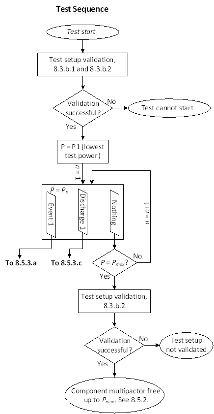 Figure 81: Illustration of test sequence
Acceptance criteria
Definitions
For all evaluations related to the requirements in clause 8.5, it is reminded that the definitions of the terms "Event" 3.2.8 "Discharge" 3.2.14 and "Multipactor Discharge Threshold" 3.2.15 are strictly applied.
Multipactor Free Equipment or component
ECSS-E-ST-20-01_1450195The tested equipment or component may be declared multipactor free up to the maximum test power if:
- No multipactor discharge or event was detected during the test in any of the detection systems at any input power up to the maximum test power, and
- the test setup was successfully validated before and after the test according to 8.3. ECSS-E-ST-20-01_1450196On a case by case basis, pending customer approval, the equipment or component may be declared multipactor free up to the maximum test power if:
- Investigations related to events or to a single non-repeatable discharge as described in clause 8.5.4 lead to the conclusion that the observed phenomena are not related to multipactor, and
- the test setup was successfully validated before and after the test according to 8.3.
Steps in case of Discharges or Events during test
ECSS-E-ST-20-01_1450197If one or several events are detected at power level n during the measurement, the following steps shall be taken:
- Keep the power constant at power level n for the remaining dwell time after the last event.
- If the power level n is equal to the maximum test power, perform an investigation according to 8.5.4 in order to establish the cause of the event.
- After completing the power step where event or events were detected, continue the test with the next power level, n+1.
- If further events are detected at power level n+1, repeat the procedure from steps 1, 2 or 3.
- If a discharge is detected during steps 1, 2 or 3 stop the test and take the multipactor discharge threshold as the level where the first event was observed.
- If no event or discharge is detected during step 3, continue the test with power level n+2.
- If further events are detected at power level n+2 or higher, repeat the procedure from steps 1, 2 and 3.
- If a discharge is detected at power level n+2 or higher, continue the test in accordance with the procedure for discharges in 8.5.3c and once the test is completed select, pending on the test result either:
- to take the multipactor threshold as the level where the first event was observed during the test, or.
- if an investigation in accordance with clause 8.5.4 concludes that the first event or events seen during the test were not related to multipactor, perform, pending customer approval, the determination of the multipactor threshold according to the procedure for discharges in 8.5.3c.
- If no further events or discharges are detected during the subsequent power steps up to the maximum test power, perform an investigation in accordance with clause 8.5.4 in order to explain the detected event or events.
An illustration of the various steps is given in Figure 82.
ECSS-E-ST-20-01_1450198The results of the investigation of 8.5.3a.9 shall be reported to the customer to conclude on the nature of the discharge or event.
 Figure 82: Illustration of test sequence following first Event
ECSS-E-ST-20-01_1450199If a discharge is detected at power level n during the measurement, the following steps shall be taken:
- Reduce the power until no discharges or events are detected.
- Keep the power at the level at which no discharges or events were detected for the nominal duration of a power step.
- Bring back the power to level n, where the first discharge was detected and keep it for the nominal duration of a power step.
- If no further discharge or event was detected during step 3, continue the test with the subsequent power steps until either a second event or discharge is detected or the maximum specified test power is reached.
- If, during steps 3 and 4, events or discharges occur, record the lowest power level where a discharge was detected as the multipactor discharge threshold.
- If, during steps 3 and 4, no events or discharges occur, select, pending on the test result either:
- take the multipactor threshold as the level where the single discharge was observed during the test, or
- perform an investigation in accordance with clause 8.5.4 in order to explain the detected potential discharge.
An illustration of the various steps is given in Figure 83.
ECSS-E-ST-20-01_1450200The results of the investigation of 8.5.3c.6(b) shall be reported to the customer to conclude on the nature of the discharge or event.
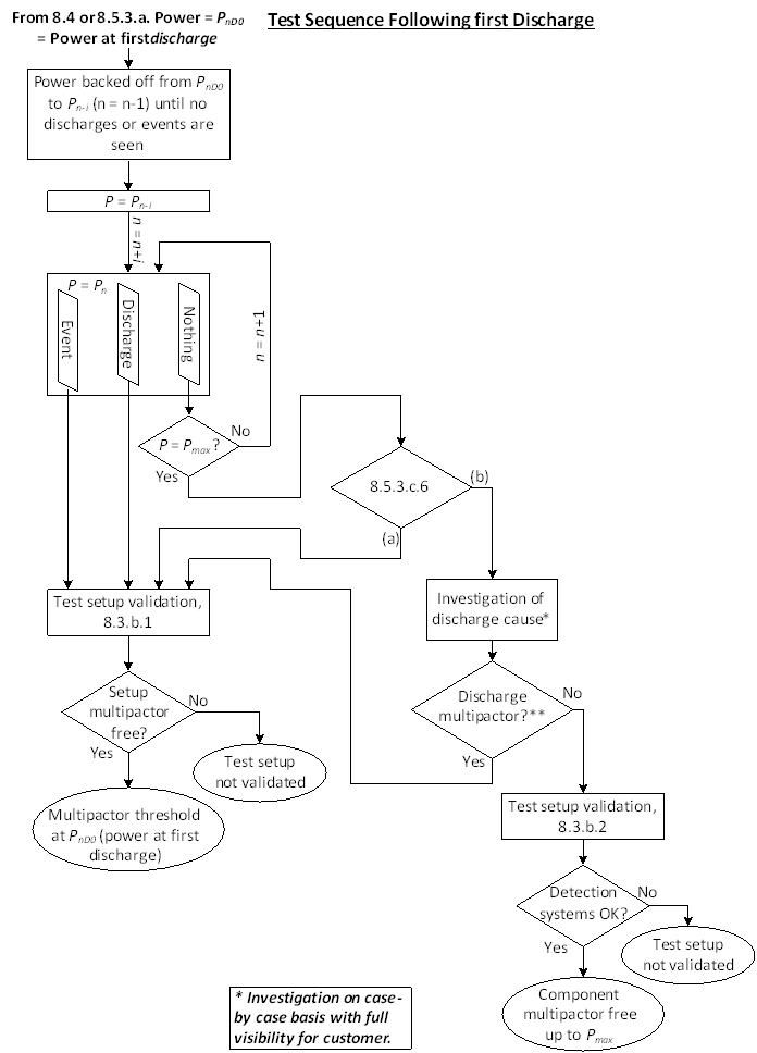 Figure 83: Illustration of test sequence following first potential discharge
Investigation of Test Anomalies
ECSS-E-ST-20-01_1450201If non-repeatable or ambiguous events or discharges have occurred, an investigation shall be performed in order to determine the root cause of the event, events or isolated discharge that was observed.
This investigation can include:
- Continued testing at higher power levels or lower duty cycle, pending approval of the customer.
- Venting of the chamber, followed by a repeated test.
- Validation of the test bed, repeating one or more of the steps described in clause 8.3.
- Evaluation of the conditions under which the event or discharge occurred. For example; Test witness getting close to the test bed, unexpected test bed shock, abrupt increment in temperature leading to a return loss change, fluctuations in the high power amplifier.
- Other aspects that are motivated by the experience and knowledge of the equipment or component supplier, the test supplier or the customer.
ECSS-E-ST-20-01_1450202The investigation of test anomalies shall be performed on a case by case basis, with full visibility for the customer.
ECSS-E-ST-20-01_1450203The investigation and the associated conclusions shall be documented in the test report, see clause 8.7.
Test procedure
ECSS-E-ST-20-01_1450204The test procedure, in accordance with the DRD of Annex C in ECSS-E-ST-10-03, shall be provided to the customer for approval and include, as a minimum, the following items:
- List of reference and applicable documents
- Detailed description of the equipment or component
- Detailed description of the test bed, as per clause 8.2.
- Test bed validation process, as per clause 8.3.
- Test parameters and detection methods to be used
- Definition of maximum test power
- Test sequence including power profile, as per clause 8.4.
- Success criteria
- Aborting criteria, when applicable.
Testing procedures for high power RF loads that are meant to be used in TVAC testing campaigns are described in the Multipactor handbook.
Test reporting
ECSS-E-ST-20-01_1450205The test report, in accordance with the DRD of Annex C in ECSS-E-ST-10-02, shall be provided to the customer for approval and include, as a minimum, the following items:
- A detailed test configuration describing the test set-up for each equipment or component, including:
- The test setup block diagram,
- Measurement accuracy (pressure, temperature and RF power),
- Locations and description of the seeding sources.
- S-parameter Measurements of the sample before and after the multipactor test campaign.
- Records over time of the environmental conditions of the DUT including temperature, pressure.
- Evidence of the test setup validation without DUT including the frequency and the maximum power applied.
- Evidence of the test setup validation with the reference sample including:
- Test frequency,
- Duty cycle,
- Input power profile versus time,
- Expected Multipactor threshold power,
- Detection System responses at the detected discharges and/or events.
- Report of the Test with the DUT including:
- Thermal bake-out parameters,
- Test frequencies,
- Duty cycle,
- Input power profile versus time,
- List of events,
- Detection System responses,
- Achieved Power w/o Multipactor.
- A list of all equipment used during the test campaign including calibration dates where relevant.
- If applicable, investigation and the associated conclusions performed according to clause 8.5.4.
- Conformances and deviations.
Secondary electron emission yield requirements
General
In this standard, the SEY is the total secondary electron emission yield.### SEY measurements justification
ECSS-E-ST-20-01_1450206If the manufacturing process or the material of any potential critical gap is changed, a representative SEY sample of the new equipment or component shall be used for SEY measurements.
Any change of manufacturing process and any change of materials can be traced by means of DPL and DML according to ECSS-Q-ST-70.
ECSS-E-ST-20-01_1450207The stability of the SEY parameters due to ageing shall be verified by SEY or Multipactor measurements.
ECSS-E-ST-20-01_1450208SEY measurements results shall be documented in a SEY Test Report to be agreed with the customer.
The SEY measurement results can be included in the qualification report of the associated material or process.
Worst case SEY measurement
ECSS-E-ST-20-01_1450209The worst case SEY measurements, for a set of SEY curves for a given material, shall correspond to the highest SEY value for each primary energy of the full primary energy range versus representative environmental conditions during life time.
Representative environmental condition during life time include at least temperature and ageing.
ECSS-E-ST-20-01_1450210In case of unexpected SEY measurement results, an investigation shall be performed and documented.
SEY measurements conditions
Environmental conditions
Handling, storage and transportation
ECSS-E-ST-20-01_1450211For all SEY samples, handling, storage and transportation shall be performed according to ECSS-Q-ST-20-08 or ESCC 20600.
ECSS-E-ST-20-01_1450212Each SEY sample shall have a dedicated logbook according to the DRD of ECSS-Q-ST-20 Annex C.
Cleanliness
ECSS-E-ST-20-01_1450213The cleanliness and contamination control policy shall be in accordance with the ECSS-Q-ST-70-01.
ECSS-E-ST-20-01_1450214Preliminary visual inspection shall be performed on the item to be measured, in order to detect any presence of visible defects, artefacts and contaminations.
ECSS-E-ST-20-01_1450215SEY measurement shall be performed on samples without preliminary treatment “as received” unless stated differently by the customer.
Pressure
ECSS-E-ST-20-01_1450216The SEY measurement shall be conducted using a high vacuum facility 10-6 hPa.
Temperature
ECSS-E-ST-20-01_1450217The temperature range of the SEY measurement shall be specified by the supplier and approved by the customer.
SEY test bed conditions
Incident electron energy
ECSS-E-ST-20-01_1450218SEY measurements of conductive and dielectric materials shall be performed from the lowest primary electron energy to an incident energy level corresponding to 1 keV including the first cross-over energy (E1) for SEY=1.
ECSS-E-ST-20-01_1450219The minimum primary electron energy achievable at the sample surface shall be as low as possible with a minimum value of at least 5 eV.
Incident angle
ECSS-E-ST-20-01_1450220The incident angle of the e-beam with respect to the normal to the surface of the sample at the incident point shall be 0° ±2°, unless other angles are specified by the customer.
Electron dose
ECSS-E-ST-20-01_1450221The incident electron dose shall not produce surface conditioning effects, modifications or charging effects of the dielectrics.
Charging requirements for dielectric samples
ECSS-E-ST-20-01_1450222Before SEY measurements, the SEY dielectric sample shall be discharged to minimize the magnitude and the space dispersion of the surface voltage and considered as the reference condition.
ECSS-E-ST-20-01_1450223For each incident energy, this reference condition shall be recovered.
ECSS-E-ST-20-01_1450224The reproducibility of the SEY curve shall be verified by measurement.
SEY sample characteristics
ECSS-E-ST-20-01_1450225SEY samples for characterization shall be manufactured with surface treatments representative of the manufacturing process and materials corresponding to the RF equipment according to DPL and DML documents.
SEY measurements can be performed on the SEY samples or on the actual equipment or component.
ECSS-E-ST-20-01_1450226The spot size of the electron beam shall be smaller than the size of the SEY sample and a SEY average value over the whole sample area be guaranteed.
SEY measurements procedure
SEY Measurements procedure documents
ECSS-E-ST-20-01_1450227The SEY measurements procedure shall include as a minimum the following items:
- List of reference and applicable documents,
- Description of the sample,
- Description of the SEY measurements facility,
- SEY measurements facility calibration process,
- Measurements parameters,
- Measurements sequence.
- 1 The sample is labelled and traced by the customer.
- 2 An example of the SEY measurement procedure can be found in the Multipactor handbook ECSS-E-HB-20-01.
ECSS-E-ST-20-01_1450228The SEY measurements report shall include the following information as a minimum: - A detailed measurements configuration describing the SEY measurements facility,
- A list of all equipment used during the SEY measurements campaign including calibration dates where relevant,
- Measurements data, including SEY as a function of the primary electron energy with uncertainties, if any, and the values of the following SEY parameters:
- first cross-over energy (E1) for SEY=1,
- maximum of the SEY (SEY_max), and
- primary energy corresponding to the maximum (Emax).
SEY measurement calibration
ECSS-E-ST-20-01_1450229Calibration of the SEY measurements facility shall be performed and the results made available to the customer.
ECSS SEY data selection
ECSS-E-ST-20-01_1450230In the case companies do not have representative SEY data to perform the analysis, the experimental SEY data of the Table 91 for Al, Au, Cu and Ag materials shall be used.
SEY data from Table 91 are taken from average values of experimental measurements of more than 20 samples for each different material. Measurements were performed at normal incidence of the primary electrons and at room temperature. The SEY samples of this table were exposed to the air. See the Multipactor handbook ECSS-E-HB-20-01 for more information.
ECSS-E-ST-20-01_1450231Table 91: SEY parameters for Al, Cu, Au and Ag materials
|
Material
|
E1
|
SEY_max
|
Emax
|
SEY_0
|
|
Al
|
17
|
2,92
|
276
|
0,8
|
|
Cu
|
19
|
2,48
|
232
|
0,8
|
|
Au
|
21
|
2,23
|
212
|
0,8
|
|
Ag
|
20
|
2,34
|
315
|
0,8
|
|
NOTE: The values of SEY_0 are extrapolated values for zero energy
| ||||
ANNEX(informative)Multipactor document delivery per review
Scope of the Table A-1 is to present relation of documents associated to activities to support project review objectives as specified in ECSS-M-ST-10.
Table A-1 constitutes a first indication for the data package content at various reviews. The full content of such data package is established as part of the contractual agreement, which also defines the delivery of the document between reviews.
The table lists the documents necessary for the project reviews.
The various document versions in a row indicate the increased levels of maturity progressively expected versus reviews. The last document versions in a row indicates that at that review the document is expected to be completed and finalized.
All documents, even when not marked as deliverables in Table A-1, are expected to be available and maintained under configuration management as per ECSS-M-ST-40 (e.g. to allow for backtracking in case of changes).
For better understanding of the Phase Review during which the relevant document is provided, the following assumptions are given:
All document deliveries are given for equipment or components under development, while for other types of equipment or components the table content can be different and tailored consequently.
Table: Multipactor deliverable document per review
|
Document or DRD title
|
EQSR
|
SRR
|
PDR
|
EQM TRR
|
EQM TRB
|
CDR
|
TRR
|
TRB
|
|
Equipment or component Statement of Compliance to Equipment or component Specifications
|
Final
|
|
|
|
|
|
|
|
|
Design Justification File(*)
|
|
Preliminary
|
Preliminary
|
|
|
Final
|
|
|
|
Multipactor Analysis
|
|
|
Preliminary
|
|
|
Final (including definition of the analysis margin)
|
|
|
|
Multipactor Test Spec & Proc
|
|
|
|
Final (including definition of the test margin) for EQM if any
|
|
Preliminary
|
Final (including definition of the test margin)
|
|
|
Multipactor Test Result
|
|
|
|
|
Final (Multipactor acceptance of the equipment) for EQM if any
|
|
|
Final (Multipactor acceptance of the equipment)
|
|
(*): Maximum power of the equipment or component over its in-orbit lifetime is justified in the Design Justification File.
| ||||||||
Bibliography
|
ECSS-S-ST-00
|
ECSS system – Description, implementation and general requirements
|
|
ECSS-E-HB-20-01
|
Space engineering – Multipactor handbook
|
|
ECSS-M-ST-10
|
Space project management – Project planning and implementation
|
|
ECSS-M-ST-40
|
Space project management – Configuration and information management
|
|
ECSS-Q-ST-70
|
ECSS product assurance – Materials, mechanical parts and processes
|