
Space product assurance
Particles contamination monitoring for spacecraft systems and cleanrooms
Foreword
This Standard is one of the series of ECSS Standards intended to be applied together for the management, engineering and product assurance in space projects and applications. ECSS is a cooperative effort of the European Space Agency, national space agencies and European industry associations for the purpose of developing and maintaining common standards. Requirements in this Standard are defined in terms of what shall be accomplished, rather than in terms of how to organize and perform the necessary work. This allows existing organizational structures and methods to be applied where they are effective, and for the structures and methods to evolve as necessary without rewriting the standards.
This Standard has been prepared by the ECSS-Q-ST-70-50 Working Group, reviewed by the ECSS Executive Secretariat and approved by the ECSS Technical Authority.
Disclaimer
ECSS does not provide any warranty whatsoever, whether expressed, implied, or statutory, including, but not limited to, any warranty of merchantability or fitness for a particular purpose or any warranty that the contents of the item are error-free. In no respect shall ECSS incur any liability for any damages, including, but not limited to, direct, indirect, special, or consequential damages arising out of, resulting from, or in any way connected to the use of this Standard, whether or not based upon warranty, business agreement, tort, or otherwise; whether or not injury was sustained by persons or property or otherwise; and whether or not loss was sustained from, or arose out of, the results of, the item, or any services that may be provided by ECSS.
Published by: ESA Requirements and Standards Division
ESTEC, ,
2200 AG Noordwijk
The
Copyright: 2011© by the European Space Agency for the members of ECSS
Change log
|
ECSS-Q-ST-70-50C TA-VOTE Draft 1
|
First issue
|
Introduction
Particulate contaminants can be hazardous to spacecraft in a number of ways including failure of precision mechanisms, light absorption and scattering, points of high local electric field and associated electrostatic discharge, and noise on electrical contacts. It is therefore important to control, measure and verify the particulate contamination levels on spacecraft systems and the environments in which they reside, in order that an assessment can be made on any hazards that may be present as a result of such contamination.
The objective of this standard is to ensure that the particle monitoring of spacecraft systems and cleanrooms utilised in the production of such systems, is carried out in an appropriate manner, and is controlled both in terms of the precision of the measurements and the reproducibility of such measurements.
Scope
This standard defines the requirements and guidelines for the measurement of particulate contamination on the surfaces of spacecraft systems and those of the cleanrooms or other cleanliness controlled areas in which they reside.
This includes the measurement of particulate contamination that is present on the spacecraft or cleanroom surfaces via the use of representative witness samples placed in the vicinity of the spacecraft hardware, the direct measurement of particulate contamination levels on surfaces of spacecraft hardware from the direct surface transfer to adhesive tape-lift samples and particulate contaminant levels within fluids used for the cleaning or rinsing of such spacecraft system components and cleanroom surfaces. This standard also defines the methods to be used for the visual inspection of spacecraft system hardware for particulate contamination.
The measurement of airborne particulate contamination is not covered in this standard and ISO 14644 “Cleanrooms and associated controlled environments” is applicable in this case.
This standard does not cover particulate contamination monitoring for spacecraft propulsion hardware which is covered in ECSS-E-ST-35-06.
This standard may be tailored for the specific characteristic and constrains of a space project in conformance with ECSS-S-ST-00.
Normative references
The following normative documents contain provisions which, through reference in this text, constitute provisions of this ECSS Standard. For dated references, subsequent amendments to, or revision of any of these publications do not apply. However, parties to agreements based on this ECSS Standard are encouraged to investigate the possibility of applying the more recent editions of the normative documents indicated below. For undated references, the latest edition of the publication referred to applies.
|
ECSS-S-ST-00-01
|
ECSS System - Glossary of terms
|
|
ECSS-Q-ST-10-09
|
Space product assurance – Nonconformance control system
|
|
ECSS-Q-ST-20
|
Space product assurance - Quality assurance
|
|
ECSS-Q-ST-70-01
|
Space product assurance - Cleanliness and contamination control
|
|
ISO 14952-3
|
Space systems - Surface cleanliness of fluid systems - Part 3: Analytical procedures for the determination of nonvolatile residues and particulate contamination
|
Terms, definitions and abbreviated terms
Terms defined in other standards
For the purpose of this Standard, the terms and definitions from ECSS-S-ST-00-01 apply.
Terms specific to the present standard
background count
measurement of the contamination levels produced by the measurement method (and associated apparatus) and the measurement environment as distinct from the inherent contamination level of the item to be measured
background subtraction
act of subtracting a background count from a measurement
black light illumination
illumination which predominantly produces light in the near UV region (310 nm to 400 nm)
bubble
volume of trapped gas encapsulated by another medium
cleanliness and contamination control plan
plan which defines the organized actions to control the level of contamination
cleanliness controlled area
area in which there are specific measures to control and monitor contamination which allows the counting of particles to be performed with sufficient accuracy as defined by the background count
cleanliness requirement specification
specification that defines the requirement for allowable contamination levels
cleanliness verification
activity intended to verify that the actual cleanliness conditions of the spacecraft system, the cleanrooms, and other environments in which the spacecraft system will reside, are in conformance with the applicable specifications and other cleanliness requirements
compatible
not deteriorating the functionality, performance and integrity of any item or surface
contamination potential
potential amount of contaminant in the source which can produce contamination defined in terms of the obscuration factor per unit time
The obscuration factor per unit time can be expressed in [(mm2/m2)/h].
contamination sensitive
article which, if exposed to contamination, can be adversely affected in terms of its designed function
effective sample area
area on a surface that has been exposed to a contamination source
lint-free
resistant to fibre generation
membrane filter
polymer film with specific pore sizes, designed to separate particles from liquids or gases
non-shedding
resistant to particle generation
obscuration factor
ratio of the projected area of all particles to the total surface area on which they rest
particle
unit of matter with observable length, width and thickness
For the purposes of this standard the particles have typical dimensions of 0,1 μm to 1000 μm.
particulate contamination
airborne or surface contamination relating to particles
particle fallout
accumulated deposit of particulate matter on a surface
representative sample
sample which is designed to be the same as another item, either in physical form or the environment in which it resides, or both
ripple
topographical in-homogeneity usually in the form of a wave pattern
sensitive surface
surface that has a high probability of damage
spectral grade
measure of solvent purity determined from its absorption spectrum
Typically spectral grade solvents have a purity of greater than 99,5 %.
tape-lift
method of transferring particulate contamination from a surface with an adhesive tape
tape-lift sample
length of transparent adhesive tape that has been used for a tape lift and subsequently applied to a clean substrate to encapsulate any contamination
trained inspector
inspector certified by a third party certification body, or with proven on the job experience that is agreed with or recognized by the customer
ultrasonic bath
bath containing liquid and a transducer which produces ultrasonic waves which produce microscopic cavitation bubbles in the liquid which aids in the removal of particles from surfaces of an item placed in the liquid
Typical frequency of ultrasonic waves is from 15 kHz to 400 kHz.
visibly clean
absence of surface contamination when examined with a specific light source, angle of incidence and viewing distance using normal or magnified vision
- 1 Different inspection methods are available, depending on:
- hardware to be inspected, in term of size and accessibility and sensitivity to contamination
- inspection distance
- light spectra (including UV), intensities and angles
- 2 The “visibly clean” level roughly corresponds to an obscuration factor smaller than 300 mm2/m2 when inspected from a distance of 30 cm to 60 cm with an oblique white light of 540 lx to 1620 lx.
- 3 Typical magnification levels range from 2x to 8x.
visibly clean standard
absence of surface contamination when examined under oblique white light of more than 540 lx and from a distance of 150 cm to 300 cm using normal vision
visibly clean sensitive
absence of surface contamination when examined under oblique white light of more than 540 lx and from a distance of 60 cm to 120 cm using normal vision
visibly clean highly sensitive
absence of surface contamination when examined under oblique white light of more than 1080 lx and from a distance of 15 cm to 45 cm using normal or magnified vision
visual inspection
act of examining an object under defined illumination and viewing conditions with normal or magnified vision
void
area devoid of matter
Abbreviated terms
The following abbreviations are defined and used within this standard:
|
Abbreviation
|
Meaning
|
|
C&CCP
|
cleanliness and contamination control plan
|
|
CRS
|
cleanliness requirement specification
|
|
IPA
|
isopropyl alcohol
|
|
ISO
|
International Organization for Standardization
|
|
LED
|
laser emitting diode
|
|
lx
|
lux
|
|
OF
|
obscuration factor
|
|
PCB
|
printed circuit board
|
|
PFO
|
particle fallout
|
|
UV
|
ultra-violet
|
|
UVA
|
ultra-violet (310 nm - 400 nm)
|
Particulate cleanliness monitoring requirements
Cleanliness requirement specification overview
ECSS-Q-ST-70-01 requires that the particulate contamination level applicable to spacecraft systems is defined in a cleanliness requirement specification (CRS). This standard also requires that the CRS explicitly defines the allowable levels of particulate contamination throughout the lifetime of the spacecraft, and that this levels are incorporated into the overall cleanliness budget for the spacecraft systems.
Cleanliness and contamination control plan
Particulate cleanliness and contamination control shall be planned in accordance with ECSS-Q-ST-70-01.
Cleanliness and Contamination Control Plan (C&CCP) identifies potential contamination sources, the effects that those sources have on the spacecraft systems in addition to identifying spacecraft systems which are contamination sensitive to particles.
Measurement methods specified in 5.1, 5.2 and 5.4 shall be employed in order to monitor and report particulate contamination levels.
Quantitative method requirements
Particles sampling from surfaces
Tape lift method
Introduction
This clause describes the tape-lift method to be used for the sampling of surfaces for the purpose of the determining particulate contamination levels, and the definition of the particle size distribution. In this case, the surface particulate is analysed using a direct transfer method, whereby a transparent adhesive tape is applied to the surface to be tested and the particles are transferred from the sample surface to the adhesive tape. The particles transferred to the tape are then analysed using an optical microscope.
An ASTM standard also exists, ASTM E 1216-06, Standard practice for sampling for particulate contamination by tape-lift.
General requirements
Any counting of particles for the purpose of determining particulate contamination levels using the tape lift method shall be performed in a cleanliness controlled area.
Sensitive surfaces shall not be analysed using the tape lift method.
In the case where adhesive residue is removed from the surface subjected to the tape-lift test, the potential damage that can be caused by the cleaning of the surface shall be assessed prior to conducting the tape-lift test.
If the sensitivity of the surface to be tested is not known, the tape lift method shall not be used unless a trial tape-lift has been conducted on a representative sample with the same surface and shows the surface not to be a sensitive surface.
The application of force on contaminant particles, present on the surface, during the performing of the tape-lift test shall not damage the sampled surface.
In the case of surfaces described in 5.1.1.2b, a non-sensitive surface that has been subject to the same environmental conditions and is representative of the sensitive surface, shall be used in place of the sensitive surface.
Apparatus
The following apparatus shall be used to perform a tape-lift analysis:
- A low-tack, transparent adhesive tape with an adhesive force of less than 0,3 N/mm.
- A tape that is free of particles, voids, bubbles, and other artefacts detrimental to the counting of particles.
- A membrane filter with a pore size less than 1 µm, and a minimum diameter of 5 cm, which provides contrast with the particulate contaminants being analyzed.
The choice of the membrane filter depends upon the nature of the particles being analysed (e.g. a white membrane filter in the case of black particles and a black membrane filter in the case of white particles). Membrane filters can have grids when statistical counting is used.
- A mask or gridded membrane filter to perform statistical counting on squares of pre-defined area.
- Non-shedding and lint-free gloves.
- Tweezers.
- Scissors or a scalpel.
- A clean container for the transport of the tape-lift sample to the measurement facility.
- 1 A clean container is a container devoid of particulate that could influence the measurement of the tape-lift sample.
- 2 The container can be sealed to prevent external contamination from reaching the internal parts of the container.
Tape-lift method
Application of the adhesive tape to the surface to be analysed shall be performed as follows:
- Remove with a velocity not exceeding 1 cm/s a minimum of 6 cm to 10 cm of the low tack, transparent adhesive tape from the tape roll.
The reason to remove the tape slowly from the roll is to minimise static electricity.
- For small surfaces (< 5 cm dimension), if a tape-lift measurement is performed to determine the local particulate contaminant levels, the dimensions of both the total surface and the surface analysed are recorded in the measurement report.
- Once removed from the roll, the tape is immediately applied to the sample surface in one direction by the application of a force of less than 0,1 N, using one gloved finger, or a folded lint-free tissue, to smooth the tape on the sample surface.
The applied tape shall have uniform adhesion to the surface, i.e. free of voids, bubbles and un-adhered areas.
If the tape, as applied on the sample surface, is not uniformly adhered, or shows the presence of ripple or bubbles, it shall be rejected and a new sample taken in a different location.
The removal of the adhesive tape from the surface to be analysed shall be conducted as follows: - Approximately 5 cm of tape are removed from the surface being analysed using a constant speed of less than 1 cm/s, at approximately 45 degrees to the sample surface.
- Sudden or uneven forces are not used.
The membrane filter shall be applied to the adhesive side of the tape using tweezers.
The tape shall be uniformly adhered to the membrane filter surface and shall be free of voids, bubbles or un-adhered areas.
The tape can be smoothed on the membrane filter as per 5.1.1.4a.3.
The remainder of the tape shall be removed from the surface using a constant speed of less than 1 cm/s.
Excess tape not attached to the membrane filter shall be removed using scissors or a scalpel.
The membrane filter/tape assembly shall be placed into the tape-lift sample holder and the sample holder lid closed.
The tape-lift sample holder shall be labelled with the time and date the tape-lift was performed, the operator performing the test, and a unique reference for the tape-lift test.
The area of the space craft system where the tape has been applied shall be inspected for any damage, remaining particulate or molecular contamination.
Any damage, particulate or molecular contamination shall be documented in the Contamination Monitoring Report specified in Annex C.
Where remaining particulate contamination has been observed, the tape-lift test shall be repeated.
The tape-lift sample shall be analysed by the microscope counting method as specified in 5.3.
Direct deposition on silicon wafers
Introduction
This clause describes the deposition on silicon wafers method to be used for the sampling of surfaces with the purpose of determining particulate contamination levels, and defining the particle size distribution. In this case, the surface particulate is analysed directly without any transfer method, i.e. the particles collected on the silicon wafer are directly analysed using an optical microscope.
The method can also be applied to other non-diffusing surfaces, e.g. glass, polished aluminium.
General requirements
Any silicon wafer witness preparation to be used for determining particulate contamination levels using the deposition on silicon wafers method shall be performed in a cleanliness controlled area.
Any counting to be used for determining particulate contamination levels using the deposition on silicon wafers method shall be performed in a cleanliness controlled area.
The location and orientation of the silicon wafers shall be representative of the items for which this monitoring method applies.
Apparatus
The following apparatus shall be used to perform a deposition on silicon wafers method:
- A silicon wafer
Typically 2 inches diameter silicon wafers are used.
- Non-shedding and lint-free gloves
- Tweezers
- A container for the exposure and transport of the silicon wafer to the measurement facility.
The container shall be devoid of particulate contamination that can influence the assessment of the silicon wafer sample.
The container shall be sealable to prevent external contamination from reaching the internal parts of the container.
The container shall provide the capability to keep in a fixed position the silicon wafer.
The container, when lying horizontal, shall keep the surface of the silicon wafer horizontal.
The container shall ensure the capability to maintain the silicon wafer horizontal during the particulate counting, without any need to remove the silicon wafer from the container.
Preparation of silicon wafers witnesses
The preparation of the silicon wafers’ witnesses shall be performed as follows:
- Using gloves and tweezers take one new or just cleaned silicon wafer.
- Visually inspect the silicon wafer surface and edge conditions.
- In case of edge damages, the silicon wafer is rejected.
- In case of particulate or non-particulate matter, or a combination of both, visible on the surface, the silicon wafer is re-clean.
- Place silicon wafer in the container.
- Perform a background measurement with the microscope counting method (see 5.3).
- Close the container.
Transportation of silicon wafers witnesses
The silicon wafer witness shall always be transported in its container and in a horizontal position, the sampling surface facing upwards.
Since transportation is relocating particles, measurement equipment is preferably located close to measurement sites.
Exposure of silicon wafer witnesses
Handling of the witnesses shall be limited to the operations needed for its preparation, transportation to the measurement site and exposure.
Any additional handling and transportation shall be documented in the Contamination Monitoring Report specified in Annex C.
Once exposed in one mode or position, the witness shall never be re-used before assessment of the contamination and cleaning.
An exposed witness should not be moved from its measurement position.
Any move of the exposed witness shall be documented in the Contamination Monitoring Report specified in Annex C.
The container shall only be opened in situ.
It is important that the person performing the witness deployment wears cleanroom garments as required for the room.
Any witness handling, deployment and measurement, shall be performed wearing non-shedding and lint-free gloves.
After exposure, the container shall be closed in-situ.
Analysis of silicon wafer witnesses
The silicon wafer witness shall be analysed with the microscope counting method as specified in see 5.3.
Rinsing (direct or indirect)
Introduction
This section describes the method for determining particle contamination levels from a liquid rinse that has been used to remove particles from the surface to be assessed.
General requirements
Any counting for determining particle contamination levels from a liquid rinse, shall be performed in a cleanliness controlled area.
The rinsing or immersion liquid shall be compatible with the material of the surface to be sampled, the specified application and the membrane filter used in the subsequent analysis.
The rinsing or immersion liquid shall be the most effective, or a combination of the most effective, in removing contaminants.
- 1 Typically, the rinsing or immersion liquid is the agent used for the last cleaning, if applicable.
- 2 When performed together with NVR analysis, the selection of the rinsing or immersion fluid is usually driven by the required NVR extraction effectiveness.
De-ionized water, IPA, MEK, acetone, ethanol and the fluids listed in ISO 14952-3 paragraph 4.4.2 should be used as rinsing or immersion liquids.
The area of the rinsed surface shall be measured.
When the measurement is not practicable, the best estimate shall be provided.
The minimum rinsed area shall be large enough to allow the verification of required cleanliness levels.
If only the internal surface of a component is sampled, cross contamination of particles from the external surface shall be avoided.
For small items that can be transported to the measurement area, the items should be transported in a clean antistatic bag, avoiding friction or movement that can generate particles.
Items that have a geometry for which simple rinsing is not demonstrated effective for particle removal shall be placed in a pre-cleaned ultrasonic bath with the solvent for at least 15 minutes and then rinsed with the solvent.
This can be applied for example to the threaded holes (that are often drilled and tapped) used for the screw attachment of fittings to parts and structures; such recesses are important sources of particle contamination that is difficult to detect.
When the ultrasonic method is used to transfer particulate to the sampling liquid, it shall be verified that ultrasonics are compatible with items and surfaces prior to sampling.
For example, ECSS-Q-ST-70-08 precludes the use of ultrasonics to PCBs populated with components.
When ultrasonics is not feasible, an equivalent method agreed with the customer shall be used.
For vertical surfaces that are fixed to a structure larger than the surface under measurement, or are otherwise unable to be removed to the measurement area, the whole surface should be rinsed with the solvent using a clean syringe, in situ, and the fluid collected in a previously cleaned container.
Method for the sampling of external surfaces on small items
Introduction
The present clause 5.1.3.3 describes the method to be used for the sampling of external surfaces on small items by liquid immersion and rinsing. This procedure does not apply to items that have only inner surfaces of interest (e.g. pipes or enclosed recesses). This method does not apply to large surfaces and large items that are not able to be immersed in an ultrasonic bath, either due to size or non-compatibility with ultrasonics. In this method, the particles from the surface to be analysed are transferred to the liquid medium and subsequently analysed using the microscope counting method described in 5.3.
Apparatus
The apparatus shall be as specified in 5.2.1, with the following additional items:
- Previously cleaned metal or glass container,
- Ultrasonic bath,
- Clean syringe for applying solvent to the surface for rinsing.
Sampling procedure
Test fluid shall be added to completely immerse the test item in the previously cleaned container.
Sampling shall be performed as follows:
- Immerse the component in the container and apply ultrasonic vibration for 5 minutes.
- Using the syringe, rinse the component with the test fluid from the solvent dispenser and add the rinsing to the immersion fluid.
- Rinse the inner surfaces of the transportation bag directly into the reservoir.
- Record the total volume of test fluid used.
- Analyse the fluid in accordance with 5.2.1.
Method for the sampling of external surfaces on large items
Introduction
The present clause 5.1.3.4 describes the method of assessing particulate contamination on large surfaces that cannot be analysed by the method described in 5.1.3.3.
Apparatus
The apparatus shall be as specified in 5.1.2.3, with the following additional items:
- Previously cleaned metal or glass container,
- Clean syringe for applying solvent to the surface for rinsing.
Sampling procedure
The sampling procedure shall be as follows:
- Using the syringe, rinse the surface to be analysed with solvent over a pre-determined area, and collect the solvent in a clean container.
- Inspect the area for any remaining particles.
- Continue to apply solvent rinses to the surface until the surface is visibly clean.
- Record the total volume of solvent used.
- Analyse the fluid in accordance with 5.2.1.
Method for the measurement of internal surfaces
Introduction
The method described in this clause is applicable to components that have internal surfaces from which fluid can be applied and extracted.
Apparatus
The apparatus shall be as specified in 5.1.2.3, with the following additional items:
- Clean container with lid to collect the solvent after rinsing,
- Petri dish.
Sampling procedure
The sampling procedure shall be as follows:
- Remove caps or plugs, or both, from the field holder and place them in a covered, pre-cleaned Petri dish;
- Fill the component with the pre-filtered test solvent;
- Reinstall the caps/plugs and vibrate the component;
- Vibrate the component;
- Extract the test fluid and analyze it in accordance with clause 5.2.1.
Volume sampling
Particles sampling from filtered liquid samples
Introduction
This clause describes a procedure for sampling, sizing and counting of particulate contamination in a liquid sample using a microscope. A known quantity of liquid sample is filtered through a membrane filter under vacuum. The particles trapped on the filter surface are sized and counted by microscopic analysis (see 5.3).
General requirements
Any counting for the purpose of particle measurements from filtered liquid samples shall be performed in a cleanliness controlled area.
The liquid sample for particle measurements from filtered liquid samples shall be selected on the basis of its compatibility with the membrane filter.
Apparatus
The following apparatus shall be used to perform particulate contamination measurements from a liquid sample:
- A membrane filter which provides contrast with the particulate contaminants being analyzed
- Sintered glass membrane filter holder
- Buchner filter flask (1 litre capacity)
- Vacuum source (vacuum pump or Venturi)
- Fluid dispenser
- Ultrapure water or solvent
- Clean syringe
- Petri dishes with covers
- Forceps
Method
Initial preparation of glassware
All of the glassware should be ultrasonically cleaned before the measurement by washing in hot water with a detergent.
The glassware shall then be rinsed with filtered de-ionised water and filtered IPA and dried.
All cleaned equipments shall be stored in a clean area with openings covered with a non-shedding and lint-free cover.
Background test
A background test shall be performed prior to the sample measurement by the following method:
- Set up the apparatus as shown in Figure 51.
- Apply vacuum to the apparatus by attaching the vacuum feed to the vacuum attachment on the Buchner flask.
- Using a clean syringe, introduce 200 ml of membrane filtered ultrapure water or the solvent used within the solvent reservoir, taking care to rinse the complete inner surface of the solvent reservoir.
- After filtration, apply vacuum for few minutes in order to dry the membrane filter.
- Using forceps, immediately place the filter in a clean Petri dish and place the cover on the Petri dish.
- Mark the Petri dish with the sample reference.
- Perform a microscopic particle count as described in clause 5.3.
- Record the background count.
Sample test
The sample test shall be performed by the method described below:
- Set up the apparatus as shown in Figure 51.
- Apply vacuum to the apparatus.
- Fill the solvent reservoir with the fluid to be analyzed.
- After filtration, apply vacuum for few minutes in order to dry the membrane disk.
- Using forceps, immediately place the filter in a clean Petri dish and place the cover on the Petri dish.
- Mark the Petri dish with the sample reference.
- Place the sample on the microscope sample stage and perform a microscopic particle count as described in clause 5.3.
- Record the sample count.
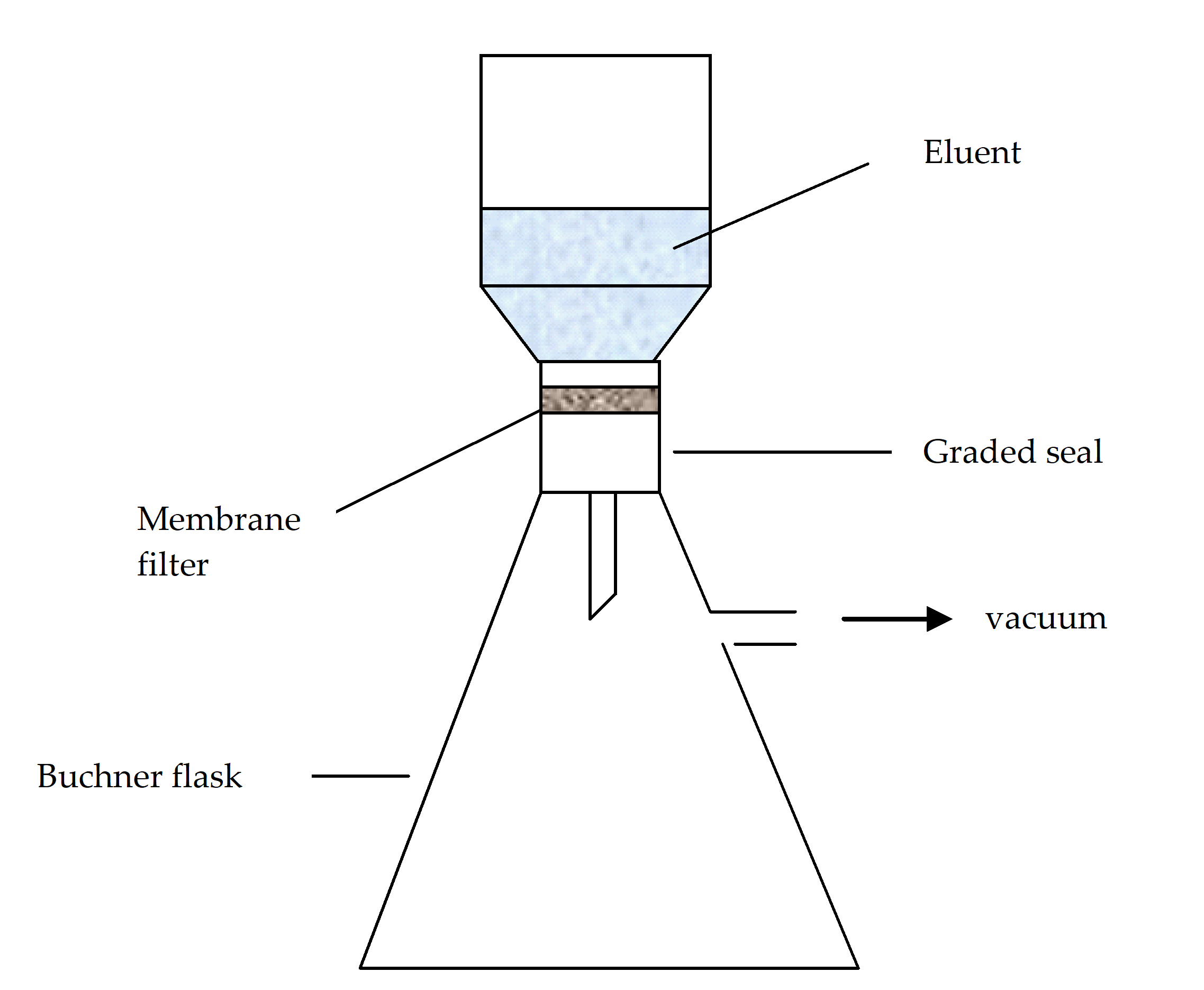 Figure 51: Schematic for vacuum filtering apparatus
Particles sampling from filtered gas samples
Introduction
This clause describes a procedure for sampling, sizing and counting of particulate contamination in a gas sample using a microscope. The particulate contamination is separated from the gas sample by passing the gas through a membrane filter, to allow a particle contamination count. This procedure is also applicable to the cleanliness verification of flow-through fluid systems assembled with cleaned components, in order to verify the cleanliness after the assembly.
General requirements
Any counting of particulate contamination in a gas sample shall be performed in a cleanliness controlled area.
The gas shall be chemically compatible with the membrane filter.
The gas pressure shall not damage the membrane filter.
Apparatus
The following apparatus shall be used to perform particulate contamination measurements from a gas sample.
- Membrane filter
- Filter holder for gas sampling
- Calibrated flow meter
- Flex tubes and connections
- Petri dishes with covers
- Fluid dispenser
- Ultrapure water or solvent (e.g. pre-filtered IPA)
- Forceps
Method
Initial preparation of sampling equipment
All of the glassware, filter holder, flexible tubes and connections should be cleaned before the measurement by washing in hot water with a detergent.
The glassware, filter holder, flexible tubes and connections should then be rinsed with filtered de-ionised water and filtered IPA and dried.
All cleaned equipments shall be stored in a clean area with openings covered with a non-shedding and lint-free cover.
Sample test
The sample test shall be performed by the following method:
- Put the membrane filter in the cleaned filter holder and attach the flow meter at the exit of the filter holder using a cleaned connecting line.
- Connect one end of a cleaned connecting line to the gas sample outlet.
- In the case of the verification of a liquid or gas delivery system, the cleaned connector should be connected to the outlet of the system.
- Connect the other end of the connection to the filter holder inlet as specified in Figure 52.
- Adjust the flow rate that assures turbulent flow and a sample volume of at least 300 dm3 ± 0,5 % and record the volume of gas.
- Disconnect the connecting line to the gas sample outlet and remove the filter holder.
- Remove the filter membrane from the filter holder with forceps, place in a clean Petri dish and place the cover on the Petri dish.
- Mark the Petri dish with the sample reference.
- Place the sample on the microscope sample stage and perform a microscopic particle count as described in clause 5.3.
- Record the sample count.
Background test
A background test shall be performed according to the procedure in clause 5.2.2.4.2, without the item to be verified.
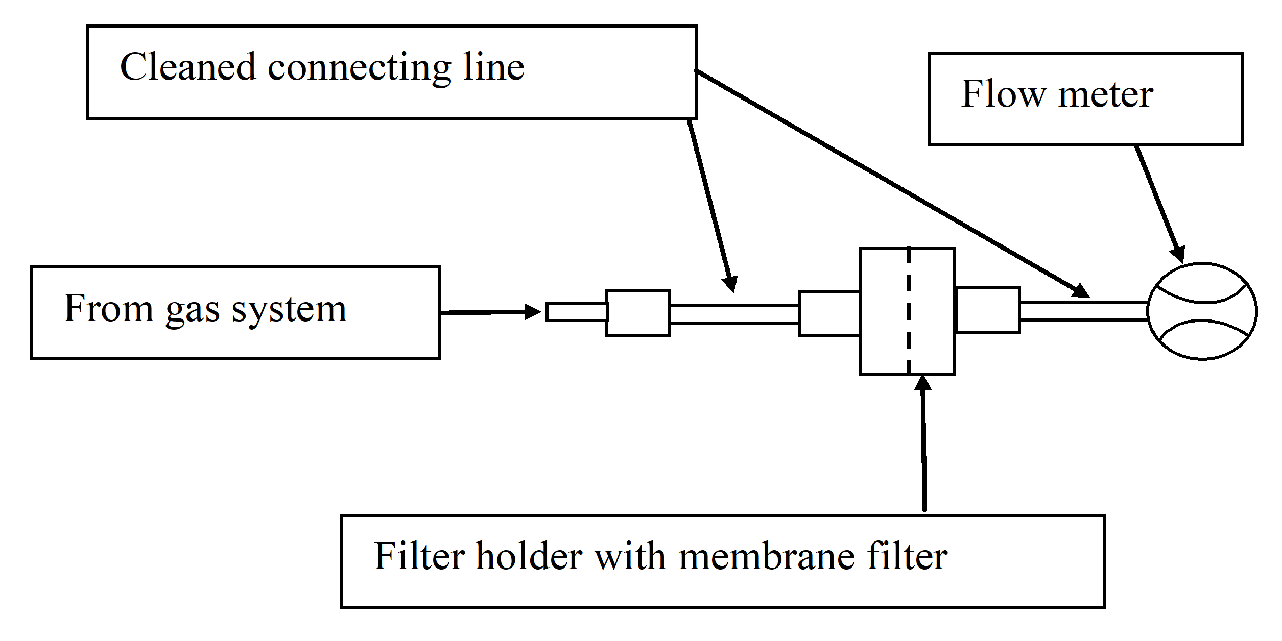 Figure 52: Gas sampling schematics
Particles sampling with automatic counters
Introduction
This section describes a procedure for sampling, sizing and counting of particulate contamination in a volume (either liquid or gas) sample using light scattering devices.
General requirements
When automatic particle counters are used they shall have demonstrated accuracy and repeatability, which correlates with microscope counting.
Any counting with automatic particles counters shall be performed in a cleanliness controlled area.
Particles counting with microscope
Introduction
The following method is applicable for the microscope counting of particles. The count is performed over five distinct particle ranges, namely particles >100 µm; between 50 µm and 100 µm; 25 µm and 50 µm; 15 µm and 25 µm; and 5 µm and 15 µm. After counting the number of particles in each size range, and calculating the areas of each individual particle over 100 µm, the obscuration factor can be calculated. This method does not apply to particles smaller than 5 µm.
The size ranges are the same as those described in the ASTM F 312-08 standard.
General requirements
The micrometer eyepiece scale shall be calibrated with a reticule at each magnification used.
A background count shall be performed to ensure that the apparatus used and the environments in which the measurement is conducted do not adversely affect the accuracy of the sample count.
The frequency of background counts shall be established between the customer and the supplier prior to the measurement campaign.
Where background subtraction is used for a determination of absolute particulate contamination levels, the reproducibility of the background count shall be established.
The background count shall be performed in the same way as the sample count.
If the background count is greater than 20 % of the particle level stated in the contamination requirement specification for the space craft system, a particle count shall not be conducted on the tape-lift or silicon wafer sample and the reasons for the high background count shall be investigated.
The use of statistical sampling shall be agreed between the supplier and the customer prior to the measurement.
Apparatus
The following apparatus shall be used to perform a tape-lift or a silicon wafer analysis:
- An optical microscope with x50, x100 and x200 magnification.
- Standard linear and globe and circle reticules.
- Flexible high intensity fibre optic light source or homogenously distributed razing light source.
The optical microscope can be equipped with a motorized stage and auto-focus capabilities for automated counting.
Method
The following method shall be applied to the microscope counting of particles:
- Define the effective sample area.
- Place the sample on the microscope sample holder.
- Fit an objective on the microscope to give an overall magnification of x50, adjust the illumination to maximise the contrast, and scan the whole effective sample area.
- Count and register particles greater than 100 m on the whole surface and calculate their area.
- Count and register particles from 50 m to 100 m:
- If the number of particles exceeds 100, and record the number of particles along with the corresponding area searched.
- If the number of particles is less than 100, scan the whole effective sample area.
- Fit an objective on the microscope to give an overall magnification of x100 and count and register particles from 25 m to 100 m:
- If the number of particles exceeds 100, record the number of particles along with the corresponding area searched.
- If the number of particles does not exceed 100, scan the whole surface.
- Count and register particles from 15 m to 25 m:
- If the number of particles exceeds 100, record the number of particles along with the corresponding area searched.
- Otherwise, scan the whole effective sample surface.
- Fit an objective on the microscope to give an overall magnification of x200 and count and register particles from 5 m to 15 m:
- If the number of particles exceeds 100, record the number of particles along with the corresponding area searched.
- Otherwise, scan the whole effective sample surface.
If the absolute value of particles is calculated by subtracting the background count from the sample count in each of the categories described 5.3.4a, it should be agreed between the customer and the supplier after an evaluation of the reproducibility of the background count.
For silicon wafers, the method can be automated by using an optical microscope equipped with a motorized stage and auto-focus capabilities. The counting is then performed by directly scanning the whole pre-defined sample area, and with the support of an image recognition software.
Statistical sampling method
If the total number of particles counted in a particle size category is greater than 50, and the particles are homogeneously distributed, then a statistical method using an integral number of unit areas containing the 50 particles may be used.
The statistical sampling shall be performed by using a mask or grid which contains a number of unit areas as described in 5.3.5c.
An example is provided in Figure 53.
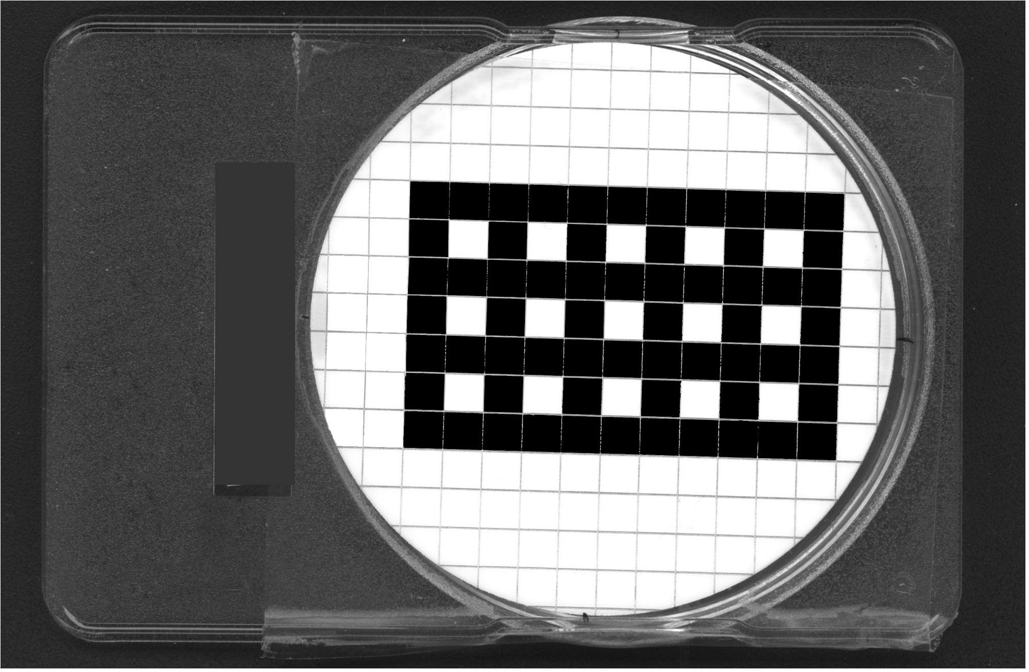 Figure 53: Mask example for statistical sampling
The statistical sampling shall be performed as follows:
- Define the effective sample area.
This is the area that is exposed to the contamination source.
- Place the sample (including grid or mask) on the microscope sample holder.
- Fit an objective on the microscope to give an overall magnification of x50, adjust the illumination to maximise the contrast, and scan the whole sample to ensure a homogeneous distribution of particles.
- Count and register particles greater than 100 m on the whole surface and calculate their area.
- Count and register particles from 50 m to 100 m one unit area at a time:
- If the number of particles exceeds 100, continue to count all the particles until the counting of the current unit area is completed, and then record the number of particles along with the corresponding number of unit areas examined.
- If the number of particles is less than 100 then scan the whole effective surface area.
- Fit an objective on the microscope to give an overall magnification of x100 and count and register particles from 25 m to 50 m one grid at a time:
- If the number of particles exceeds 50, continue to count all the particles until the counting of the current grid is completed, and record the number of particles along with the corresponding number of grids examined.
- If the number of particles is less than 50 then scan the whole filter surface.
- Fit an objective on the microscope to give an overall magnification of x200 and count and register particles from 50 m to 100 m one grid at a time:
- If the number of particles exceeds 50, continue to count all the particles until the counting of the current grid is completed and record the number of particles along with the corresponding number of grids examined.
- If the number of particles is less than 50 then scan the whole filter surface.
Conversion of particle count to obscuration factor
The conversion of the microscopic particle count to obscuration factor shall be defined by the following formula:
![]() where:
where:
OF is the obscuration factor (mm2/m2),
Particle area is the total projected area of all of the particles and is given by:
![]() where:i is the range number
where:i is the range number
di is the lower limit of the ith size range
Di is the upper limit of the ith size range
Ni is the number of particles counted in the ith size range
For particles greater than 100 μm in dimension, the area in the formula in 5.3.6a should be calculated for each particle.
The sampled area in the formula in 5.3.6a shall be the total area over which the particle count was conducted.
- 1 Table 51 shows the average area for each particle size range.
- 2 If the whole effective sample area has been used, then this is also, the sampled area. In all other cases, the sampled area is the area that has actually been used for the particle count.
Table 51: Ranges and average areas for a single particle in each range
|
Range
|
Lower limit (µm)
|
Upper limit (µm)
|
Average area of one particle (µm)2
|
|
i
|
di
|
Di
|

|
|
1
|
5
|
15
|
98,1
|
|
2
|
15
|
25
|
334
|
|
3
|
25
|
50
|
1230
|
|
4
|
50
|
100
|
4910
|
|
5
|
>100
|
Not applicable
|
To be determined for each particle
|
Particle fallout measurement (PFO)
Introduction
This section describes the method for determination of the particle fallout (PFO) on or near critical spacecraft systems, in clean working areas, test facilities, storage or transport containers and other environments in which spacecraft hardware will reside by means of a photometric method.
Small particles from 0,5 μm to 5 μm determine the airborne class figure to an extent greater than 90 %, whereas particles greater than 5 μm determine the particle fallout on surfaces to an extent of 99 %.
General requirements
For the PFO method, a clean sensor plate with a dark specular surface and known surface area shall be used in addition to a photometric device that measures the area projected by the particulate fallout on the surface of the sensor.
The photometric device should be calibrated by correlation with visual microscope counting.
A PFO measurement shall not be carried out if the background count on the sensor plate is greater than 20 mm2/m2.
Apparatus
The following apparatus shall be used:
- Photometric PFO monitor
- PFO sensor plates
- Non-shedding and lint-free tissue
- Spectral grade solvent compatible with PFO sensor plate
- Self-sealing, clean anti-static bag
- Clean transport container
- Stand and or clamps for sensor fixation
Cleaning of the sensors
The cleaning of the sensors shall be performed in an area with a cleanliness level such that a background level measurement of less than 20 mm2/m2 can be achieved over the entire duration of the sensor exposure to the measurement environment.
The sensor shall be cleaned by drag wiping the surface with a non-shedding and lint-free tissue that is wetted with spectral grade solvent.
Wiping should be performed in one direction only, from the sample holder to the free end of the sensor plate.
If a background level of less than 20 mm2/m2 cannot be reached after several cleanings, the glass plate should be rinsed with spectral grade solvent with the same or higher solvation power of chloroform or acetone with the aid of a syringe and the cleaning repeated.
If a background count of less than 20 mm2/m2 still cannot be reached after performing steps 5.4.4a to 5.4.4d, an investigation into the high background count shall be conducted.
Packing of PFO sensors
The cleaned sensor shall be packed in a re-useable self-sealing and clean antistatic bag, and returned after exposure.
The bag specified in 5.4.5a should be made of polyethylene.
Packing shall be carried out in such a way as to avoid friction between the sensor and the bag.
The reason is that this can generate particles.
Having been placed in this intimate packing, the sensors shall be stored in a container for transport.
The cleaned sensor shall be packed on the bench on which it was cleaned in such a way that contamination is avoided.
Transportation of PFO sensors
Sensors shall always be transported in the sealed bag provided and in a horizontal position, the sampling surface facing upwards.
Since transportation is relocating particles, measurement equipment is preferably located close to measurement sites.
Exposure of PFO sensors
Handling of the sensor shall be limited to the operations needed for its preparation, transportation to the measurement site and exposure.
Any additional handling and transportation shall be documented in the Contamination Monitoring Report specified in Annex C.
Once exposed in one mode or position, the sensor shall never be re-used before assessment of the contamination and cleaning.
An exposed sensor should not be moved from its measurement position.
Any move of the exposed sensor shall be documented in the Contamination Monitoring Report specified in Annex C.
The intimate packing of the sensor shall only be opened in situ and the sensor deployed immediately.
The sensor shall be deployed in such a way to avoid any contact with, or any passage above, the measuring surface.
It is important that the person performing the measurement wears cleanroom garments as required for the room.
For sensor handling, deployment and measurement, antistatic gloves shall be used.
Requirements 5.4.7d to 5.4.7h shall apply when the sensors are packed after exposure.
Location of the PFO sensors
Monitoring of clean rooms and test facilities
The sensors shall be placed within the fallout area of potential contamination sources.
For a cleanroom these typically include the cleanroom entrance, the centre of work activities, areas in the vicinity of moving parts, areas in the vicinity of filtered air inlets.
Monitoring of spacecraft system in test facilities or clean rooms
The sensors shall be fixed to the spacecraft system or fixed as close as possible to it, in the same environment.
During the transport or storage of the spacecraft system, the sensor shall be held in a particular position which permits a representative particle collection with respect to the spacecraft system.
Fixation of the PFO sensors
The PFO sensors shall be fixed onto the space hardware by clamping if possible.
If the sensor cannot be fixed onto the space hardware, it shall be placed in the closest position not causing operational limitations.
Sensors should be placed parallel to the sensitive surfaces to be monitored.
A stand or tripod shall be employed to minimise air turbulence in the setting of the sensors.
If existing tables, cupboards, cabinets, racks or equipment surfaces are used to put the sensor on, the surface shall be pre-cleaned using non-shedding and lint-free wipes, wetted by immersion in spectral grade methanol, ethanol or IPA, to approximately 1 m2 around the location.
To fix a PFO sensor, only adhesive tape approved by the customer shall be used.
For example, during transportation or for moveable parts.
If an adhesive tape in accordance with 5.4.9f is used to fix a PFO sensor, any contact with the sampling surface shall be avoided.
Visual inspection method requirements
Introduction
This clause specifies the visual inspection methods to be used for the assessment of particulate cleanliness on spacecraft components, subsystems and systems. Hardware that pass this kind of inspection can be declared “visible clean”. The visual inspection methods are qualitative methods, while the previously methods described in clause 5 are quantitative. Visual inspection depends on many factors such as operator, lighting conditions, inspection angle and the optical properties of the item being inspected. Nevertheless, visual inspection is simple and effective, and can be applied almost anywhere. A rough correlation between visually clean and PFO can be found in ECSS-Q-ST-70-01.
General requirements
The area where the inspection takes place shall have a cleanliness level that does not affect the results of the inspection.
The transportation of an item to an inspection area shall not affect the results of the inspection.
If the transportation is via a non-cleanliness controlled area, the item to be inspected shall be transported in a clean, sealed container, and only removed from the container in the inspection area.
Any handling procedures and contamination control requirements (as described in the C&CCP) for the item to be inspected shall be followed during the inspection, paying particular attention to contamination sensitive items.
Sensitive surfaces or surfaces subjected to contamination assessment shall not be touched during the inspection.
If the article is manipulated for inspection then it shall be with non-shedding and lint-free gloves.
No cleaning or other manipulation of contamination shall take place on the item during the inspection.
The light source should be compatible with the illuminated surface.
Heat generated by high intensity fibre optic light sources shall not damage temperature sensitive items.
Any anomalies or observations shall be noted on a dedicated inspection sheet in the form of a sketch or photograph.
Only trained inspectors shall perform the visual inspection.
In the case where there is doubt as to the interpretation during the visual inspection on the space craft system, it is a good practice that another trained inspector verifies the findings.
The methods for inspection of space craft system shall be agreed between the customer and the supplier prior to inspections being performed.
In case of disagreement between the results of a visual inspection conducted on spacecraft system and measurements conducted on witness samples and other indirect measurements, the former results shall be used.
In the case of a major nonconformance being discovered during a visual inspection the following shall be done:
- the customer is immediately informed and the article left in the as-inspected condition;
- a customer representative is invited to verify the results of the inspection. Photographs should be used to record any defects and anomalies found during the visual inspection.
Visual inspection of small items
Visual inspection of small contamination sensitive items
General
Introduction
This method is applicable to the inspection of contamination sensitive items which can be moved easily to, and inspected in, a dedicated inspection booth.
Apparatus
The following apparatus shall be used for the inspection of small items:
- Inspection booth
- Flexible high intensity fibre optic or LED light source
- Matte black background
Method
The item shall be placed on a clean surface inside the inspection booth.
The illumination source shall be manipulated with respect to the item in order to maximise the contrast between the surface and any in-homogeneities.
Any observations shall be noted on the dedicated inspection sheet, as they are observed during the inspection.
For VC sensitive detections, the illumination direction shall be oriented close to the direction of observation, or at grazing incidence angle.
This is almost parallel with the observed surface.
Highly reflecting surfaces should be illuminated at grazing angle to observe particles with their shadow.
- 1 The sensitivity of particles detection depends on the surface nature. Particles on a matte black surface are often easier to observe. For transparent or translucent items, side illumination can be used.
- 2 Fibre optic inspections can be conducted inside cleanrooms and other cleanliness controlled areas. In this case, the background light is reduced in order to increase the contrast.
Using black light illumination
Introduction
This method is applicable to the inspection of organic fluorescing particles on contamination sensitive items. It is important to note that metallic and other non-fluorescing particles cannot be easily detected using this method and that in this case the method described in 6.4 is applicable.
Apparatus
The following apparatus shall be used for the inspection of small items:
- Black light inspection lamp
- 1 A black light inspection lamp provides illumination that is rich in the near ultra-violet (UVA, 320 nm - 380 nm) region of the electromagnetic spectrum.
- 2 There is a risk for the operator related to the use of black light lamps.
- Digital camera
Method
For small items that are taken to a dedicated inspection facility, the item shall be placed on a clean surface (that has previously been inspected with the black light lamp) inside the inspection booth.
Illumination from external sources shall not impair the inspection.
The black light should be moved to illuminate the whole surface to be inspected.
Any observations shall be noted on the dedicated inspection sheet, as they are observed during the inspection.
Photographs should be taken during the inspection, and incorporated in the inspection record.
Visual inspection of small non sensitive contamination items
Introduction
This method is applicable to the inspection of small items, which can be moved easily to, and inspected in, a dedicated inspection bench.
Apparatus
The following apparatus shall be used for the inspection of small items:
- Inspection booth with white-light, 10 W - 20 W fluorescent lamp.
- Matte black background.
A typical clean air, laminar flow bench can be used as an inspection booth as long as external lighting is switched off and a matte black background is used.
Method
The inspection of small components shall be made at a distance of less than 50 cm using a 10 W to 20 W, white-light, fluorescent tube as the illumination source.
The article shall be manipulated with respect to the illumination source in order to maximise the contrast between the surface and any in-homogeneities.
Any observations shall be noted on the dedicated inspection sheet, as they are observed during the inspection.
If necessary, magnification can be used for the visual inspection. When the magnification is used it is indicated on the inspection sheet or photograph.
In situ visual inspection of spacecraft
Introduction
This method is applicable to the visual inspection of space craft system in cleanrooms and other areas in which they reside. It is specifically applicable for metallic and other non-fluorescing particles.
Apparatus
The apparatus to be used for the in situ inspection of spacecraft system shall be incorporated in the inspection method agreed between the supplier and the customer.
Cleanrooms and other areas where spacecraft system reside have a large variation in lighting conditions. In addition, areas to be inspected have varying levels of accessibility. This is taken into consideration when agreeing an inspection method and associated apparatus to be used for the inspection.
The apparatus used for the inspection shall be compatible with the cleanliness levels for the environment in which the spacecraft system resides.
Method
The method used for the visual inspection shall be compatible with the space craft system and the environment in which it resides.
A risk assessment shall be made prior to the inspection to assess any risks of damage to the spacecraft hardware taking into account the accessibility of the area to be inspected.
Any observations shall be noted on the dedicated inspection sheet, as they are observed during the inspection.
Photographs should be taken during the inspection, and incorporated in the inspection record.
Quality assurance
Records
The supplier shall retain test records of the particles contamination monitoring for at least ten years or in accordance with the project business agreement requirements.
The test records shall be composed of:
- the specific particles contamination requirements documented in the request for particle contamination monitoring with the DRD in Annex A,
- the particle contamination requirement specifications and procedures documented in conformance with the DRD in Annex B,
- the report on particle contamination monitoring established in conformance with the DRD in Annex C,
- the report on visual inspection established in conformance with the DRD in Annex D,
- a conclusion with respect to the compliance with the project requirements (acceptance criteria) and associated nonconformances.
Report
The supplier shall apply the “Test report” requirements of ECSS-Q-ST-20, for the establishment of the test report.
The supplier shall submit the test report to the customer for approval.
Acceptance criteria and nonconformance
Acceptance criteria shall be defined (on beforehand) in common agreement between the supplier and the customer.
The supplier shall record any suspected or actual equipment failure as project nonconformance report in conformance with ECSS-Q-ST-10-09.
This is to ensure that previous results can be examined to ascertain whether or not re-inspection and re-testing is needed.
The supplier shall notify the customer of the nonconformance details.
Traceability shall be maintained throughout the process from incoming inspection to final measurements and calculations, including details of the test equipment and personnel employed in performing the task.
ANNEX(normative)Request for particle contamination monitoring - DRD
DRD identification
Requirement identification and source document
This DRD is called from ECSS-Q-ST-70-50, requirement 7.1b.1.
Purpose and objective
The purpose of this request is to confirm:
the need to monitor the particle contamination for spacecraft or cleanrooms materials, and
that its related requirements are in conformance with the project applicable particle contamination requirements.
Expected response
Scope and content
The request for particle contamination monitoring shall include or refer to the following information:
- objective of the monitoring activity,
- applicable documents,
- background and justification to the monitoring activity,
- location(s) of sampling, witnesses, inspection areas,
- description of the methods to be used for sampling and counting particles contamination,
- deliverables.
Special remarks
None.
ANNEX(normative)Particulate contamination monitoring procedure (Work proposal) - DRD
DRD identification
Requirement identification and source document
This DRD is called from ECSS-Q-ST-70-50, requirement 7.1b.2.
Purpose and objective
The particulate contamination monitoring procedure (Work proposal) defines the monitoring activity for particle contamination proposed by the supplier in response to the DRD Request for particle contamination monitoring (see Annex A). The work proposal for Particulate contamination monitoring is prepared by the supplier, which is responsible for the monitoring activity, and it is submitted to the customer for review and approval.
Expected response
Scope and content
Objectives of the monitoring activity
The work proposal shall describe the objectives of the monitoring activity.
Test procedures and reference to standards
The work proposal shall contain a statement of compliance with respect to the applicable DRD "Request for particle contamination monitoring" and to ECSS-Q-ST-70-50 for the applicable methods.
The Work proposal shall describe and justify the selected test method(s) and in house procedure(s) for particulate contamination monitoring.
Facilities, tools and equipments
The work proposal shall describe facilities, tools and equipments used.
Environmental conditions
The work proposal shall define the environmental conditions that have an influence on the measurements, such as temperature, humidity, pressure, light level(s).
Expected test output
The work proposal shall contain the expected particle contamination monitoring output.
Problem and nonconformance handling
The work proposal shall include the procedure for the handling of problem and nonconformance as described in ECSS-Q-ST-10-09.
List of deviation from the conditions initially requested by the customer
The procedure shall contain the list of deviation from the conditions initially requested by the customer.
Special remarks
None.
ANNEX(normative) Report on particle contamination monitoring - DRD
DRD identification
Requirement identification and source document
This DRD is called from ECSS-Q-ST-70-50, requirement 7.1b.3.
Purpose and objective
The purpose of the report on particle contamination monitoring is to provide all information pertinent to the measurement of particulate contamination using the methods defined in ECSS-Q-ST-70-50 clause 5. This document is applicable to both the measurement of particulate contamination of spacecraft systems and controlled areas.
Expected response
Scope and content
Requesting authority
The report shall contain the name, organization and address of the requesting authority.
Measurement authority
The report shall contain the name, organization and address of the measurement authority.
Project
The report shall contain the name of the project for which the measurement has been carried out.
A project can be either related to the monitoring of spacecraft systems or controlled areas.
Spacecraft system
The report shall contain the name of the spacecraft system on which the measurement of particulate contamination has been performed, if any.
Facility
The report shall contain the name and class of the facility where the measurements have been performed.
Manufacturer
The report shall contain the name of the manufacturer of the spacecraft system/subsystem/component on which the measurement has been performed, if any.
Applicable documents
The report shall contain the applicable document list and the reference document list including the list of procedures to be applied and of standards/specifications to comply with.
Specific measurement method
The report shall define what specific measurement method has been used for the measurement of the particulate contamination.
Apparatus
The report shall define all apparatus used in the measurement.
Particle contamination samples
The report shall include a unique reference that identifies each background and particle contamination sample taken.
Duration of exposure
The report shall describe the exposure duration for each background and particle contamination sample taken.
Measurement location
The report shall contain:
- a description of the location where each particle contamination measurement has been performed;
- a description of any potential contamination sources observed and their position with respect to the measurement;
- the position of any critical surfaces observed and their position with respect to the measurement location.
The description can include schematics, pictures and text.
Background measurement
The report shall contain the results of the applicable background measurement.
Particle contamination measurements
The report shall contain the results of all particle contamination measurements carried out.
Signature or quality stamp
The report shall include the signature or quality stamp of the inspector.
Observations and anomalies
The report shall include any observations and anomalies found during the set-up and execution of the particle contamination measurement.
Handling
The report shall contain all the information related to handling conditions, including packaging, transport and storage, starting from sampling until measurement(s) completion.
Special remarks
Although the report contains the information specified C.2.1, the structure to present this information is not imposed.
ANNEX(normative) Report on visual inspection - DRD
DRD identification
Requirement identification and source document
This DRD is called from ECSS-Q-ST-70-50, requirement 7.1b.4.
Purpose and objective
The purpose of the report on visual inspection is to provide all information pertinent to the visual inspection using the methods defined in ECSS-Q-ST-70-50 clause 6.
Expected response
Scope and content
Requesting authority
The report shall contain the name, organization and address of the requesting authority for the inspection.
Inspector
The report shall contain the name of the person conducting the inspection and name and address of the organization he/she belongs to.
Project
The report shall contain the name of the project for which the inspection has been carried out.
A project can be either related to the monitoring of spacecraft systems or controlled areas.
Spacecraft system
The report shall contain the name of the spacecraft system on which the inspection has been performed, if any.
Facility
The report shall contain the name and class of the facility where the measurements have been performed.
Manufacturer
The report shall contain the name of the manufacturer of the spacecraft system/subsystem/component on which the inspection has been performed, if any.
Applicable documents
The report shall contain the applicable document list and the reference document list including the list of procedures to be applied and of standards/specifications to comply with.
Specific inspection method
The report shall define what specific inspection method has been used.
Apparatus
The report shall define all apparatus used for the inspection.
Inspection article
The report shall contain a description and unique reference for each spacecraft system that has been inspected.
Inspection area
The report shall contain a description of the area in which the inspection has taken place.
Inspection conditions
The report shall contain a description of the inspection conditions including the following as a minimum:
- Illumination source
- Illumination source to inspection article distance and angle
- Viewing angle to the inspection article
- Any magnification used for the inspection Inspection location
The report shall contain:
- a description of the location where each inspection has been performed;
- a description of any potential contamination sources observed and their position with respect to the inspection;
- the position of any critical surfaces observed and their position with respect to the inspection location.
The description can include schematics, pictures and text.
Inspection date and time
The report shall include the date and time when the inspection took place.
Signature or quality stamp
The report shall include the signature or quality stamp of the inspector.
Observations and anomalies
The report shall include any observations and anomalies found during the inspection and a short description of the inspector’s observations.
This can be in the form of properly annotated photographs.
Special remarks
Although the report contains the information specified C.2.1, the structure to present this information is not imposed.
Bibliography
ECSS-S-ST-00 ECSS System - Description, implementation and general requirements
ECSS-E-ST-35-06 Space engineering - Cleanliness requirements for spacecraft propulsion hardware
ECSS-Q-ST-70-08 Space product assurance - Manual soldering of high-reliability electrical connections.
ASTM E 1216-06 Standard practice for sampling for particulate contamination by tape-lift
ASTM F 312-08 Standard test methods for microscopical sizing and counting particles from aerospace fluids on membrane filters
ISO 14644 Cleanrooms and associated controlled environments