
Space product assurance
Ultracleaning of flight hardware
Foreword
This Standard is one of the series of ECSS Standards intended to be applied together for the management, engineering and product assurance in space projects and applications. ECSS is a cooperative effort of the European Space Agency, national space agencies and European industry associations for the purpose of developing and maintaining common standards. Requirements in this Standard are defined in terms of what shall be accomplished, rather than in terms of how to organize and perform the necessary work. This allows existing organizational structures and methods to be applied where they are effective, and for the structures and methods to evolve as necessary without rewriting the standards.
This Standard has been prepared by the ECSS-Q-ST-70-54C Working Group, reviewed by the ECSS Executive Secretariat and approved by the ECSS Technical Authority.
Disclaimer
ECSS does not provide any warranty whatsoever, whether expressed, implied, or statutory, including, but not limited to, any warranty of merchantability or fitness for a particular purpose or any warranty that the contents of the item are error-free. In no respect shall ECSS incur any liability for any damages, including, but not limited to, direct, indirect, special, or consequential damages arising out of, resulting from, or in any way connected to the use of this Standard, whether or not based upon warranty, business agreement, tort, or otherwise; whether or not injury was sustained by persons or property or otherwise; and whether or not loss was sustained from, or arose out of, the results of, the item, or any services that may be provided by ECSS.
Published by: ESA Requirements and Standards Division ESTEC, P.O. Box 299, 2200 AG Noordwijk The NetherlandsCopyright: 2017© by the European Space Agency for the members of ECSS## Change log
|
ECSS-Q-ST-70-54C
|
First issue.
|
Introduction
This ECSS Standard describes the procedures to be used to clean to a level of cleanliness beyond the scope of the ECSS-Q-ST-70-01, and to control the cleanliness level of flight hardware prior to and following a posteriori to the application of the ultracleaning process. The intended objective of the ultracleaning process is to remove all surface contamination (particulates, biologic material cell debris and chemical molecular contamination) on flight hardware, with no specific limit in geometric dimension or contamination levels. This includes removal of biological material for avoidance of false positive results during investigation of extra-terrestrial samples or environments.
Scope
This standard addresses process descriptions, process validation, cleanliness control and monitoring, recontamination prevention, quality assurance as follows:
PROCESSES DESCRIPTIONS, including
Detergent cleaning
Alcohol cleaning
Ultrapure water cleaning
Liquid boundary layer disruption cleaning
Multiple solvent cleaning (JPL procedure)
Vacuum bakeout
Supercritical fluids cleaning
Carbon dioxide snow cleaning
Plasma cleaning
Pyrolysis
Criteria for selecting other/novel processes
PROCESS VALIDATION
Test material selection
Preparation of test materials for process application
Deposition of contaminants
Description of test conditions
Verification of cleanliness level
CLEANLINESS CONTROL AND MONITORING, including
Micro/nano imaging techniques
Spectrometry techniques
Spectroscopy techniques
Chromatography techniques
RECONTAMINATION PREVENTION
Packaging systems
Protective covers
Storage
QUALITY ASSURANCE
This standard may be tailored for the specific characteristic and constrains of a space project in conformance with ECSS-S-ST-00.
Normative references
The following normative documents contain provisions which, through reference in this text, constitute provisions of this ECSS Standard. For dated references, subsequent amendments to, or revision of any of these publications do not apply. However, parties to agreements based on this ECSS Standard are encouraged to investigate the possibility of applying the more recent editions of the normative documents indicated below. For undated references, the latest edition of the publication referred to applies.
|
ECSS-S-ST-00-01
|
ECSS system - Glossary of terms
|
|
ECSS-Q-ST-10-09
|
Space product assurance - Nonconformance control system
|
|
ECSS-Q-ST-20-08
|
Space product assurance - Storage, handling and transportation of spacecraft hardware
|
|
ECSS-Q-ST-70
|
Space product assurance - Materials, mechanical parts and processes
|
|
ECSS-Q-ST-70-01
|
Space product assurance - Cleanliness and contamination control
|
|
ISO 14644-9: 2012
|
Cleanrooms and associated controlled environments - Part 9: Classification of surface cleanliness by particle concentration
|
|
ISO 14644-10: 2013
|
Cleanrooms and associated controlled environments - Part 10: Classification of surface cleanliness by chemical concentration
|
Terms, definitions and abbreviated terms
Terms from other standards
For the purpose of this Standard, the terms and definitions from ECSS-S-ST-00-01 apply, in particular for the following terms:
cleanliness
qualification
test
validation
verification
For the purpose of this Standard, the terms and definitions from ECSS-Q-ST-70-01 apply, in particular for the following terms:
cleanroom
off-gassing
Terms specific to the present standard
bioaerosol
dispersed biological agents in a gaseous environment
[ISO 14698-1:2003]
biological contamination
contamination of materials, devices, individuals, surfaces, liquids, gases or air with viable particles.
- 1 Depending on the context, biological contamination can be considered as organic or as particulate contamination. A bacterial cell has about 1E-13 g (organic content of one cell is below the detection limit of most chemical methods).
- 2 Problem is that, apart from growing, cells and spores often have extracellular material that can be more mass than the cell itself.
cleanliness (of a solid surface)
condition of a solid surface where the amount of contamination is controlled to a specific level
Example of amount of contamination include particle, chemical molecular or viable
contaminant
any particulate, chemical molecular, non-particulate and biological entity that can adversely affect the product or process
decontamination
reduction of unwanted matter to a defined level
direct measurement method (DMM)
measurement method where the contamination that is to be determined is being assessed without any intermediate steps
[adapted from ISO 14644-9:2012]
indirect measurement method (IMM)
measurement method where the contamination that is to be determined is being assessed with intermediate steps
[adapted from ISO 14644-9:2012]
surface cleanliness of chemicals (SCC)
presence on the surface of a product or instrument of molecular, chemical, non-particulate, species in the adsorbed or deposited state which can have a deleterious effect on the product, process or equipment in the cleanroom or controlled environment
[adapted from ISO 14644-10:2013]
surface cleanliness of particles (SCP)
class of surface particle cleanliness is a grading number stating the maximum allowable surface concentration, in particles per m², for a considered size of particles, SPC Classes 1 to 8
[adapted from ISO 14644-9:2012]
surface cleanliness particles (SCP) classification
level (or the process of specifying or determining the level) that represents maximum allowable surface concentrations, in particles per square metre, for considered sizes of particles, expressed in terms of an ISO SCP Class N
[ISO 14644-9:2012]
surface particle concentration
number of individual particles per unit of surface area under consideration
[ISO 14644-9:2012]
thin film contamination
layers of critical contaminants that range from the nanometre scale to the micrometre scale
viable particle
particle that consists of, or supports, one or more live microorganisms
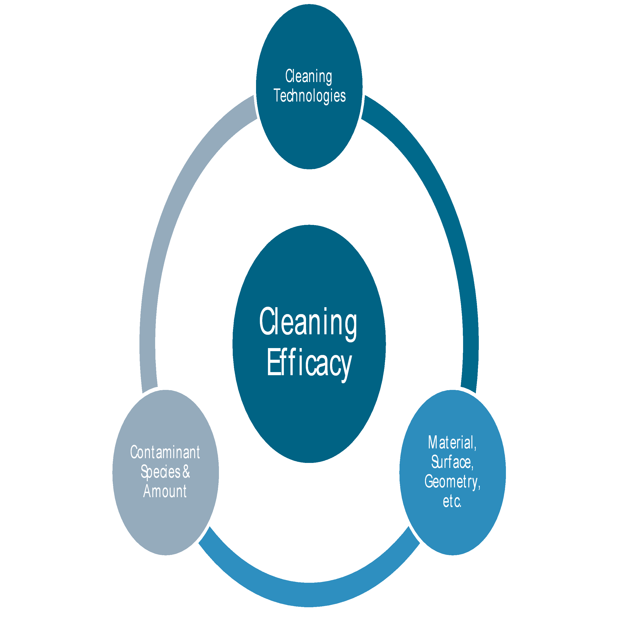
cleaning efficacy
removal of specific contaminants from a surface by a cleaning process, determined by the final accomplished surface cleanliness, in respect to the initial surface cleanliness
- 1 Cleaning efficacy can be expressed in absolute (surface concentration) or relative (percentage) terms.
- 2 In general, repetitive application of the same cleaning process results in consecutive decreasing efficacy.
Abbreviated terms
For the purpose of this Standard, the abbreviated terms from ECSS-S-ST-00-01 and the following apply:
|
Abbreviation
|
Meaning
|
|
DRD
|
document requirements definition
|
|
ppm
|
parts per million (10-6)
|
Nomenclature
The following nomenclature applies throughout this document:
The word “shall” is used in this Standard to express requirements. All the requirements are expressed with the word “shall”.
The word “should” is used in this Standard to express recommendations. All the recommendations are expressed with the word “should”.
It is expected that, during tailoring, recommendations in this document are either converted into requirements or tailored out.
The words “may” and “need not” are used in this Standard to express positive and negative permissions, respectively. All the positive permissions are expressed with the word “may”. All the negative permissions are expressed with the words “need not”.
The word “can” is used in this Standard to express capabilities or possibilities, and therefore, if not accompanied by one of the previous words, it implies descriptive text.
In ECSS “may” and “can” have completely different meanings: “may” is normative (permission), and “can” is descriptive.
The present and past tenses are used in this Standard to express statements of fact, and therefore they imply descriptive text.
Principles
Cleaning techniques: Contamination removal
Introduction
In the simplest case contamination can be defined as foreign matter, but in relation to this standard is considered any particulate, chemical molecular, non-particulate and biological entity on a surface that can adversely affect the product or process. Increase of contamination leads generally to cumulative build-up.
Surface contamination, such as particles in the micrometre range, microbiological contamination or airborne and surface molecular contamination, has become a significant hazard in many areas of industry.
Figure 41 shows schematically typical types of molecular and particulate contamination.
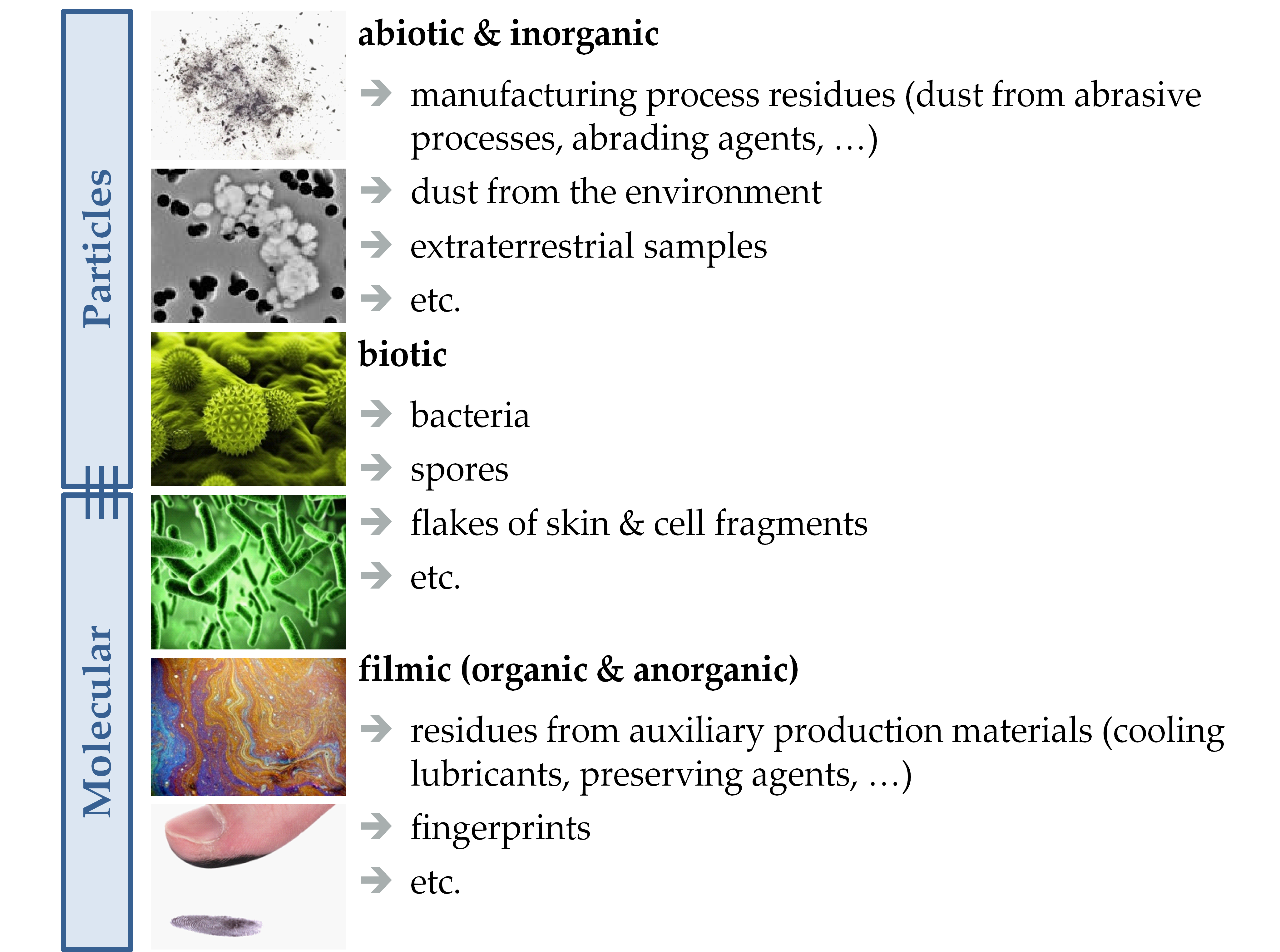 Figure 41: Typical types of molecular and particulate contamination
The deposition of contamination on surfaces for example occurs in the following three steps:
Aerodynamic transportation to the boundary layer
Transportation inside the boundary layer
Contamination coming in contact with the surface
Contamination in the micro- and nanometre range can lead to the failure of complete units, impairment of performance, or incorrect test results. Therefore, for many applications, it is essential to ensure that contamination is reliably kept away from component surfaces.
This objective is not easy to achieve, especially if one considers particles smaller than 10 µm. These particles adhere to a surface through very strong bonding interactions: covalent bonding, ionic bonding, van der Waals forces, hydrogen bonding, dipole-dipole and electrostatic interactions, or a combination of these.
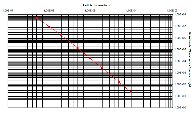
By using model approaches, the attractive and adhesive forces occurring between particles and surfaces can be theoretically calculated. The calculations deviate slightly from reality but if, for example, the magnitude of only the van der Waals force is compared with particle weight, essential information about the magnitude of the forces of attraction can still be obtained (see Figure 42).
|
|
Figure 42: Relationship between van der Waals force and weight in dependence upon particle diameter (model according to Hamaker for Al particles on Al substrate)
Van der Waals force exceeds particle weight by a factor of 108 for particles of diameter 0,5 µm. Relationships are especially pronounced in the case of small particle diameters (particle diameter of < 10 µm). Whereas van der Waals forces are linearly dependent upon the diameter over several orders of magnitude, particle diameter is cubic to weight.
As the adhesive forces of particles on surfaces are the decisive parameters for cleaning surfaces in contamination-sensitive areas, the choice of cleaning method therefore plays a crucial role.
The theoretical forces of adhesion are proportional to particle size, while the removal forces varies between the second or third power to the particle diameter thus requiring an increasingly larger force to overcome the adhesion force between the particle and the substrate as the particle size is reduced
At sufficiently thick chemical molecular contamination layers the contaminants will exhibit bulk-like characteristics where the required energy for removal is independent of layer thickness. At low levels (e.g. few molecular layers) the surface of the substrate becomes a significant factor and an increasing amount of energy is required for removal. Consequently it becomes also increasingly difficult to maintain surface cleanliness.
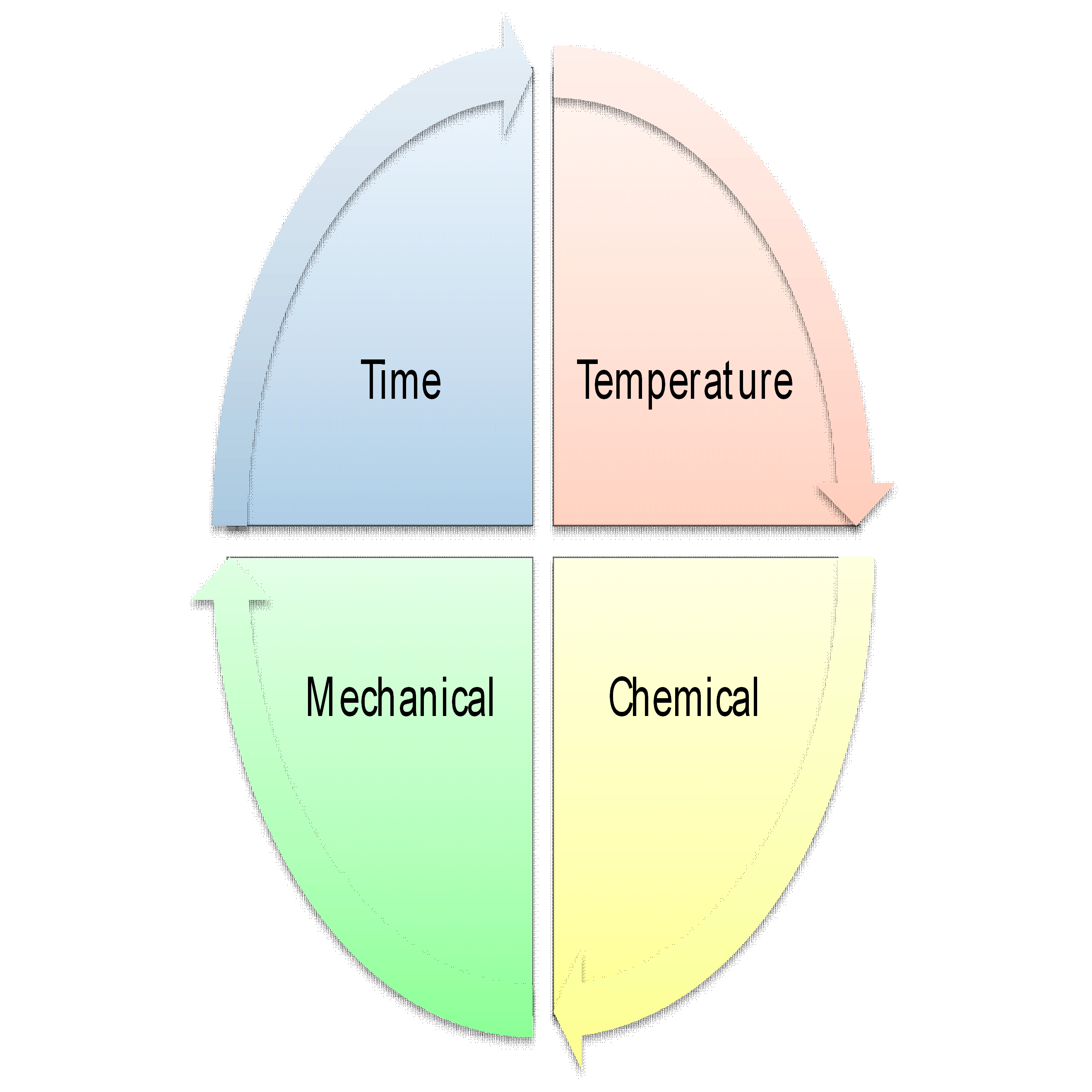
Cleaning principles and related techniques are described in more detail in clause 4.1.3. In general, there are four parameters that influence the cleaning efficacy: Chemical, mechanical, temperature and time. These factors are all inter-correlated, i.e. the change of one factor has an influence on the others. For example the reduction of temperature can be compensated by increase in cleaning time or more aggressive cleaning. This is not limited to the type of cleaning process alone, but also to type of contamination, surface characteristics and process parameters (Figure 43).
|
|
|
Figure 43: Influences on the cleaning efficacy
Ultracleaning
Table 41 shows typical cleanliness levels and their verification techniques for precision cleaning of space hardware. This is considered a coarse summary of what can be typically achieved. In practice, better or worse performance is possible depending on the surfaces to be cleaned and methodological differences in cleanliness verification.
Table 41: Typical cleanliness levels and their verification techniques on spacecraft surfaces
|
Cleaning process
|
Cleanliness verification
|
Typical limits of verification
| ||
|
Particles
|
Molecular
|
Bio
| ||
|
Precision cleaning
|
Visible, unaided eye *
|
300 ppm *
|
1E-06 g/cm2 *
|
n.a.
|
|
Witness plates
|
20-50 ppm
|
2-3E-08 g/cm2
|
n.a.
| |
|
* This method is not considered quantitative, the achievable cleanliness levels are indicative and depend on type of illumination, viewing angle and distance, type of contamination and surface, and can be operator dependent.
| ||||
In the context of ultracleaning, the quantitative limit for cleanliness level is considered below that provided in Table 41. It is possible that at very low levels, the three different classes of contamination cannot anymore be clearly discriminated, e.g.:
Bioburden can contribute significantly to molecular contamination
Bioburden can be considered a particle in size significantly below the traditional µm range
Bioburden is often associated with particles, and PFO measurements may show a correlation with bioburden
The morphology of molecular contamination can exhibit particulate-like character
A procedure to remove the performance driving single class can inherently cover the others
There is no clear discrimination between precision and ultracleaning, in the context of this standard, the term ultracleaning applies when traditional methods are insufficient.
Cleaning principles
The cleaning principles that are currently available can be broadly split in to 6 general groups based on the type of cleaning action (Figure 44 and Annex E) and include the following examples:
Blasting Cleaning, this includes such methods as sand-blasting and water blasting where a material is impinged on to the surface to be cleaned (Annex E.1).
Mechanical Cleaning, this includes wiping and brushing where another physical surface is worked against the surface to be cleaned (Annex E.2).
Fluidics Cleaning, this includes washing, and ultrasonic cleaning where the surface to be cleaned is fully immersed in a cleaning fluid (Annex E.3).
Chemical Cleaning, this includes etching and leaching where the material to be removed is dissolved in a solvent (Annex E.4).
Solvent Cleaning, this includes detaching and stripping where the chemical action removes the surface contaminant (Annex E.5).
Thermal Cleaning, this includes evaporating and annealing where an application of heat can affect contaminant removal (Annex E.6).
Special Cleaning (not completely classifiable in the so far mentioned conventional procedures), this includes Plasma Chamber cleaning; UV-light cleaning; LASER cleaning; hot vacuum purge and Supercritical CO2 (Annex E.7).
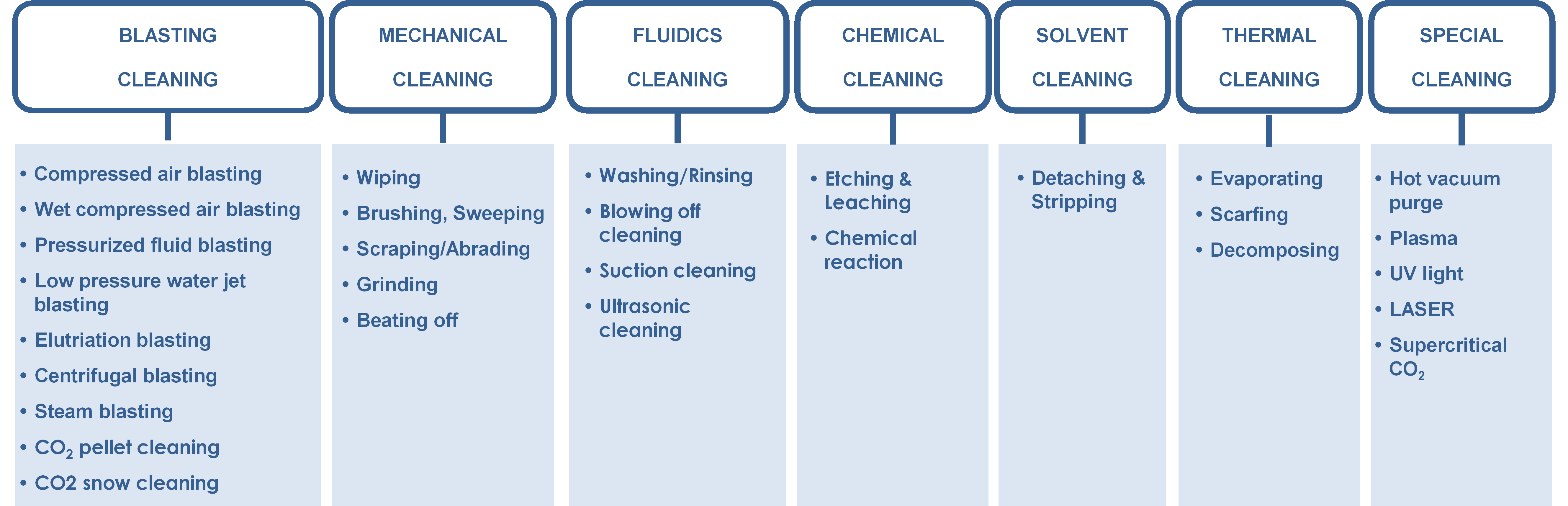 Figure 44: Available cleaning principles and related techniques
Trade-off process
A trade-off is used (see Figure 45) that considers all current cleaning techniques to derive an end-to-end process being optimised to clean hardware.
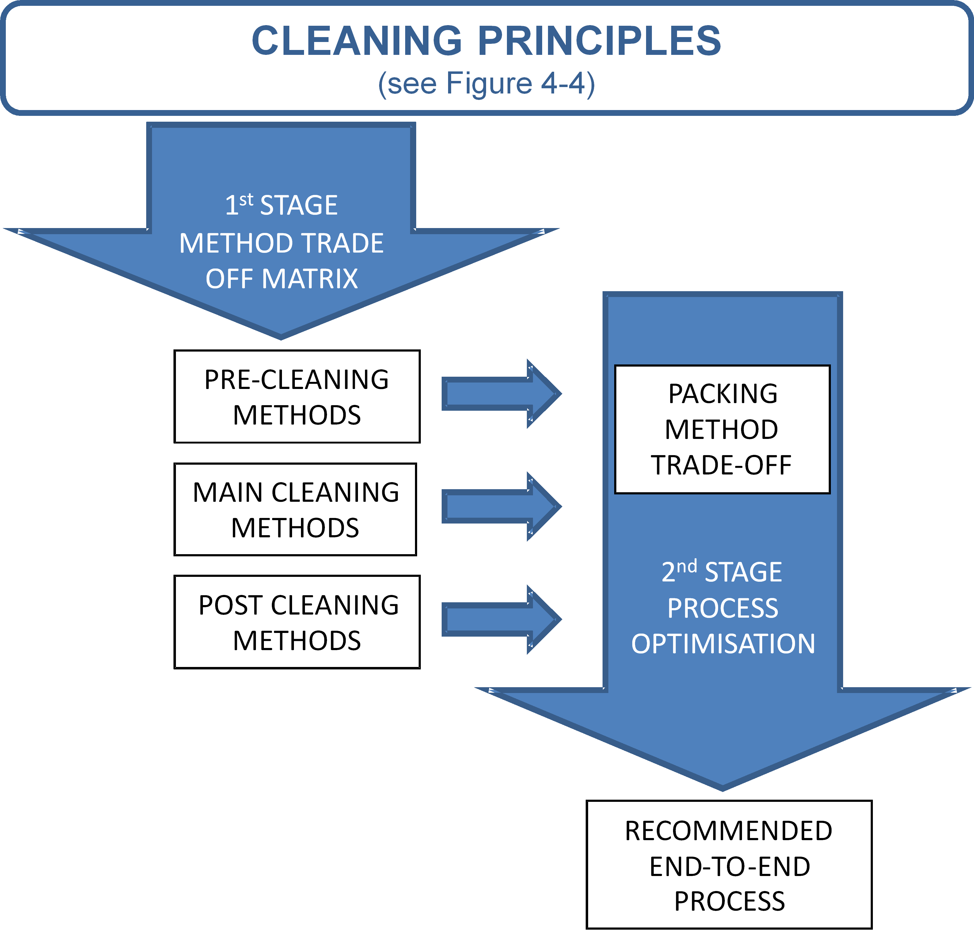 Figure 45: Two stage trade-off method
The trade-off approach takes into account both methods and processes where a cleaning method is one stage of an end-to-end process consisting of the following process stages:
PRE-cleaning method
MAIN-cleaning method
POST-cleaning method
PACKAGING method
The first stage of the trade-off considers a large number of cleaning methods and conduct an initial broad analysis by means of a trade-off matrix. The analysis also identifies the suitability of these methods to PRE-cleaning, MAIN-cleaning and POST-cleaning. Depending on the case, it is possible not to apply all process stages. For example a simple case can lead to the application of only the main or pre plus main or main plus post process stages.
Based on the results of the first stage, the second stage considers the PACKAGING method and a smaller number of end-to-end cleaning processes with the objective of optimising these processes to suit the needs of the cleaning hardware.
Selection of an end-to-end cleaning process
Figure 46 shows a logic flow for an end-to-end cleaning process for hardware.
This logic flow has been optimised based on the analysis and results of the 1st stage trade-off matrix and the PACKAGING method trade-off and fully takes into account all considerations of the end-to-end process, i.e.:
PRE-cleaning method
MAIN-cleaning method
POST-cleaning method
PACKAGING method
The logic flow for the PRE-cleaning is determined by whether the Flight Hardware can be immersed in liquid. PRE-cleaning methods that immerse the flight hardware in a liquid are preferred to non-immersive methods due to their particulate efficacy and in some cases organic efficacy as well.
Any cleaning method needs to take into account the type of contaminant(s) which need to be removed, and the material or hardware compatibility with any intended process. A PRE-clean may be needed to remove gross contamination but this can be achieved by wiping (wet or dry). The decision whether to have a POST-cleaning is determined by whether the PRE-clean and MAIN-clean left (or introduced) organic residue.
For the PACKAGING the method used depends on the duration of storage, level of off-gassing material in Flight Hardware and whether the Flight Hardware to be transported.
For long-term storage and transport there are 4 alternatives. The best option is a low off-gassing Transport Box followed closely by a Sealed Box with Argon. The use of an ultrapure N2 purged box is best used if there is the possibility of organic recontamination due to the unavoidable use materials in the flight hardware that can off-gas over a long period (typically 2 years).
For short term storage, typically less than 5 days (e.g. temporary storage prior to assembly), it is recommended that triple or double layer pouches or Al-foil and polyethylene bag be used. These offer a convenient single-use storage solution that maintain cleanliness levels.
In all cases it is crucial that any packaging material in direct vicinity of the hardware has no influence on the cleanliness state of the hardware it encloses, e.g. molecular migration in polymer materials can lead to contamination in long-term.
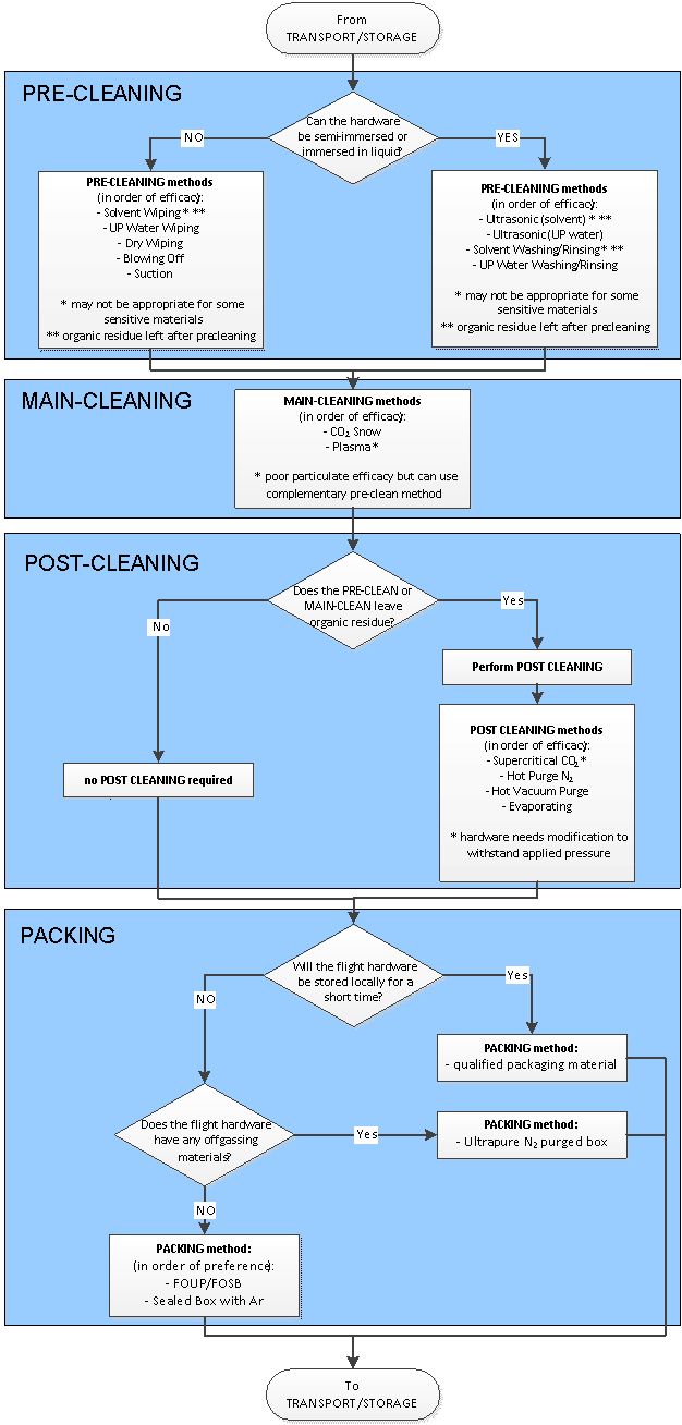 Figure 46: Logic flow for the selection and optimisation of an end-to-end cleaning process for hardware
Requirements
Specifying process
General
The customer shall provide a request for ultracleaning in conformance with the DRD in Annex A.
The supplier shall provide an ultracleaning work proposal to the customer for review and approval in conformance with the DRD in Annex B.
The supplier shall provide an ultracleaning report to the customer for review and approval in conformance with the DRD in Annex C.
NCRs generated during ultracleaning process applications shall be in conformance with requirements from clause 5 to clause 6 of ECSS-Q-ST-10-09.
Unless specified by the customer, cleanliness and contamination control shall be applied for space hardware in conformance with requirements from clause 5 of ECSS‐Q‐ST‐70‐01.
Specifying process means
Facilities
The work area shall be at a cleanliness level that does not compromise the functionality of the test items.
Cleanliness level of a work area shall be in compliance with cleanliness requirements of the hardware agreed with the customer.
Unless specified by the customer, the ambient conditions for the work areas shall be (22 ± 3) °C with a relative humidity of (55 ± 10) %.
Equipment, reagents and consumables
The supplier shall specify the list of the equipment, reagents and consumables necessary to set up and run the customer approved cleaning procedures.
Definition of end-to-end cleaning process
Test samples
The test samples shall be made of representative materials and surface finish compared to the flight hardware.
It is important to consider that the inherent simplicity of the test samples do not reflect the complex geometry of the actual hardware and therefore lead to a possible overestimation of cleaning efficacy.
Presence of in-process witness samples shall be agreed with the customer.
Ideal surfaces such as silicon wafers are useful for calibration purposes or the demonstration of the cleaning performance under ideal conditions, but are not suitable sample substrates for general process validation.
The geometry of the witness plates shall be simplified to allow quantitative analysis by the selected techniques.
Witness plates can be installed in different hardware.
For process validation an interpretation shall be provided that allows the transfer from simplified test geometry to real geometry.
Uncertainty margin shall be agreed with the customer.
The surface area of the test samples shall be such that the specified sensitivity within the uncertainty margin of the detection technique can be reached.
- 1 If surface area of the test samples is limited, it is possible to improve the sensitivity of the analysis by increasing the number of samples.
- 2 The process can be optimized by correlation of sample size and limit of detection for different detection methods.
Definition of critical contamination and tracers
The critical contaminants shall be identified in type, chemical identity, and representative surface concentration.
Critical contaminants can be particulate, biological and chemical.
The critical contaminants shall be representative for the expected hardware contamination in terms of type, amount, and surface interaction.
Correlation between model and real contamination can be made, e.g. by estimation of cleaning efficacy via adhesion forces.
Tracer constituents for the various contaminants shall be identified in type, chemical identity, and representative surface concentration, in case needed by the selected analytical technique.
The selected contaminants and tracers shall be quantifiable by the selected analytical techniques within the uncertainty margin specified in the requirement 5.2.1e.
Due to limits of the analysis techniques (e.g. desorption temperature, magnification, contrast) model substances can be chosen that provide sufficient similarity to real contamination but can be quantitatively captured.
Application process for critical contaminants and tracers
The distribution of contaminants applied across the surface of the test samples shall be determined.
The quality of the distribution process of contaminants shall be subject to customer approval.
The application process shall represent the real contamination transfer mechanism.
The nature of the representation, specified in 5.2.3b, of real contamination transfer mechanism shall be described.
Transfer mechanism considerations can include e.g. vacuum transfer vs. application from solution for molecular contamination or application from suspension vs. powder for particulate contamination.
Customer and supplier shall agree on stabilisation time before application of cleaning process.
It can be generally observed that adhesion of contaminants increases over time.
The target contamination levels shall be representative of the hardware and agreed with the customer.
In case the analytical limitations require deviations from requirement 5.2.3e, the contamination levels shall be agreed with the customer.
Selection of analytical techniques
A direct analytical technique should be used instead of an indirect technique.
- 1 A direct analytical technique is preferred as far as it does not affect the test sample surface representativeness.
- 2 A direct analytical technique is one that quantifies residual contamination without removing it from the surface first.
- 3 An indirect analytical technique is one that requires processing to quantify what contamination has been removed from the surface.
Selected analytical techniques shall be agreed with the customer.
An overview of possible analytical techniques (quantification of present residual contamination) is provided in Annex F.
The dynamic range of the selected technique shall allow quantitative analysis of contamination before and after cleaning to the specified accuracy.
For indirect analytical techniques that involve contamination transfer it shall be ensured that the transfer process is uniform over the entire sample surface.
Definition of test matrix
A test matrix shall be specified by the supplier to provide the most suitable combinations of substrates, contaminants, and analytical techniques.
As not all analytical techniques are suitable to be performed on all substrates, it is important to optimize the entire analytical process.
Number of replicates shall be agreed with the customer.
The supplier shall demonstrate that number of replicates conform with the uncertainty margin specified in the requirement 5.2.1e.
Cleaning processes
The cleaning processes and media shall be selected on the basis of their compatibility with the materials or items to be cleaned and its efficiency in removing contaminants.
- 1 Material compatibility includes performance stability such as stress cracking, stress corrosion cracking, thermo-optical properties, adhesion, thermal properties.
- 2 This includes compatibility with solvents or other chemicals, high pressure gases such as CO2 and N2, applied temperature (low or high) and possibly chemical effects, plasma, and cleanliness verification processes.
- 3 If the desired cleanliness level cannot be achieved by a single process several processes such as PRE-, MAIN-, and POST-cleaning can be used.
Cleaning aids or utensils shall not increase the contaminant levels of the items to be cleaned.
Cleaning efficacy
General
The cleaning efficacy shall be determined for each process step as a process indicator by assessing the level of contamination before and after cleaning.
The final cleaning state is most relevant, however intermediate cleaning levels influence the overall cleaning success.
An overall cleaning efficacy shall be determined comprising all process steps specified in clause 5.2.7.1a.
The statistical confidence level of the cleaning efficacy shall be derived using a customer agreed statistical approach.
The cleaning efficacy shall be calculated as follows:
|

|
[5-1]
| |
|
|
[5-2]
| |
|
where
|
|
|
|
Eabsolute
|
is the absolute cleaning efficacy (in units of C)
| |
|
Erelative
|
is the relative cleaning efficacy (%)
| |
|
Cbefore
|
is the surface cleanliness b before cleaning
| |
|
Cafter
|
is the surface cleanliness b after cleaning
| |
Classification system
The following process variables shall be specified for cleaning efficacy:
- Cleaning technique
- Nature and amount of contaminant species
- A = Non-viable particles: Initial contamination state in ISO SCP classes according to ISO 14644-9 (Table 1)
- B = Viable particles
- C = Molecular contamination: Initial contamination state in ISO SCC classes according to ISO 14644-10 (Table 1)
- Substrate specification
- Nature of bulk material in conformance with requirements from DML from Annex A from ECSS-Q-ST-70
- Nature of surface finish
- Method of contamination analysis
- D = Direct analysis
- I = Indirect analysis
- 1 � For the requirement 5.2.7.2a.1 abbreviated designations can be used such as sCO2 for CO2 snow cleaning or PC for plasma cleaning
- 2 For the requirement 5.2.7.2a.3(b) relevant parameters for the nature of the surface finish include surface roughness and possible application.
- 3 For the requirement 5.2.7.2a.4(a) direct analysis means that the level of contamination is directly observed on the surface. Abbreviated designations can be used such as for Scanning Electron Microscope (SEM), Light Microscope (LM), Fourier Transform Infrared (FTIR) spectroscopy.
- 4 For the requirement 5.2.7.2a.4(b) indirect analysis means that the level of contamination is observed by what can be removed. Abbreviated designations can be used such as for thermal desorption and subsequent Gas Chromatography and Mass Spectroscopy (TD-GC/MS).
Reporting of cleaning efficacy
The relative cleaning efficacy shall be reported in the form E[(5.2.7.2a.1) – (5.2.7.2a.2) – (5.2.7.2a.3) – (5.2.7.2a.4)] = xx %
Examples for reporting cleaning efficacy for particulate and molecular contamination are provided in Annex H.
The following quality control information shall be provided:
- Sample conditioning for standardized initial contamination state before cleaning
- Exposure time of contamination
- Storage condition
- Sample geometry
- 1 For the requirement 5.2.7.3b.1 exposure time of contamination is time between defined contamination and cleaning.
- 2 For the requirement 5.2.7.3b.2 examples of storage condition are temperature, humidity, environment.
The following process-specific information shall be provided: - Cleaning parameters
- Process or technique of applying contaminants
- Manufacturing process for substrate samples
- Operating parameters of analysis systems
- 1 For the requirement 5.2.7.3c.1 examples of cleaning parameters are chemicals, steam pressure, cleaning bath, storage technology.
- 2 Examples of manufacturing process in the requirement 5.2.7.3c.3 include moulding, grinding, milling, polishing, coating.
Validation of end-to-end cleaning process
For indirect validation of the cleaning process the levels of contamination after production and after application of a tracer shall be at agreed levels between customer and supplier.
Illustration for indirect validation of cleaning efficacy is given at Figure 51
Direct determination of cleaning efficacy should be used instead of indirect determination.
Illustration for direct determination of cleaning efficacy is given at Figure 52
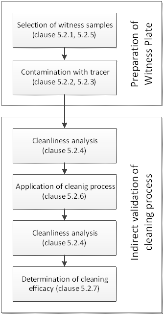 Figure 51: Cleanliness validation logic for using witness plates
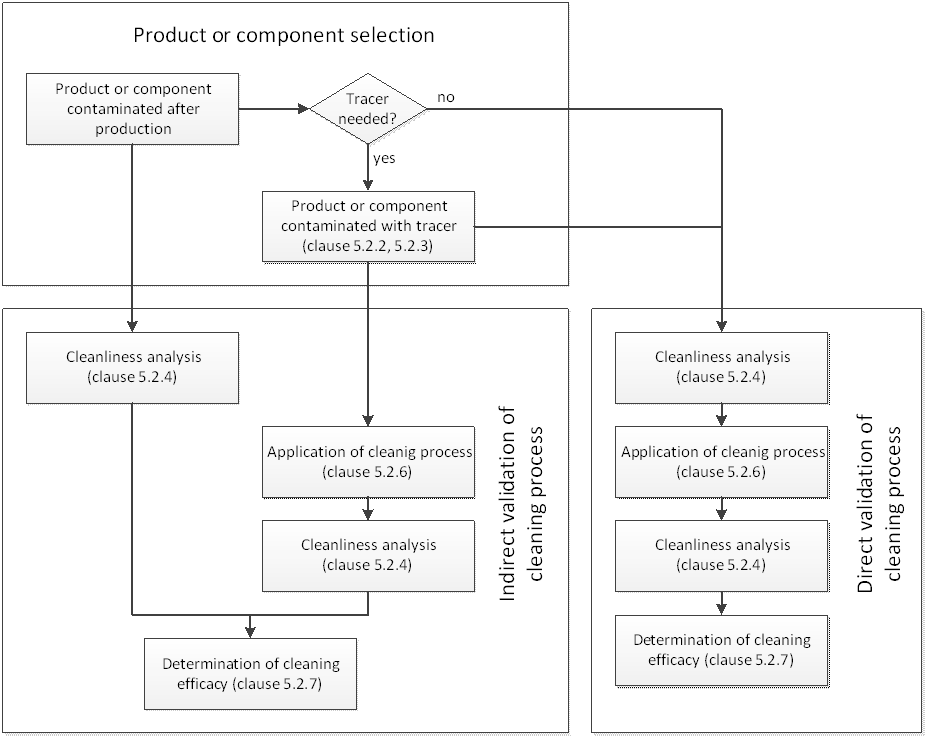 Figure 52: Cleanliness validation logic for using products or components
Packaging, containerization, transportation, storage
At any point from final cleaning to delivery to the customer, packaging, containerization, transportation, and storage shall be maintained to the customer specified cleanliness level and performed in accordance with requirements from clause 4 to clause 7 of the ECSS-Q-ST-20-08.
Requirements from clause 5.4.4 of ECSS-Q-ST-70-01 shall be applied.
The packaging concept shall be submitted to the customer for approval.
The contamination witness sensors shall be packaged with the hardware to allow subsequent verification of surface cleanliness levels.
ANNEX(normative)Request for ultracleaning - DRD
DRD identification
This DRD is called from ECSS‐Q‐ST‐70‐54, requirement 5.1.1a.
Purpose and objective
The document “Request for ultracleaning” of flight hardware specifies ultracleaning activities requested by the customer to ensure that the materials to be ultracleaned are acceptable for use:
with respect to the specific application of the customer, and
prior to its validation and approval for flight as an item of the DML, DPL, or DMPL
Expected response
Scope and content
The Request for ultracleaning shall include or refer to the following information:
- Objective of the ultracleaning.
- Background and justification to the ultracleaning.
- Items to be ultracleaned.
- Description of ultracleaning requirements and acceptance criteria.
- Description of recontamination prevention requirements.
- Deliverables.
Special remarks
None.
ANNEX(normative)Ultracleaning work proposal - DRD
DRD identification
This DRD is called from ECSS‐Q‐ST‐70‐54, requirement 5.1.1b.
Purpose and objective
The Ultracleaning work proposal is a document that defines the ultracleaning activity, as proposed by the ultracleaning supplier.
Expected response
Scope and content
The work proposal shall include or refer to the following technical information:
- A proposed work description giving:
- The objectives of the ultracleaning activity
- Ultracleaning facilities, procedures and reference to standards
- Cleanliness verification plan
- Traceable identification of items, materials, hardware
- Ultracleaning conditions
- Expected ultracleaning process output
- Recontamination prevention procedures and reference to applicable standards.
- A proposed settlement describing the ultracleaning procedures and any deviation from the conditions initially requested by the customer.
To item 1(b): This includes, for example, international standards, in-house procedures, or academic reference sources.
To item 1(e): This means environment, properties evaluated and measurement techniques.
To item 1(g): This includes, for example, international standards, in-house procedures, or academic reference sources.
The work proposal shall include or refer to the following financial and administrative information:
- Responsible person for the activity.
- List of deliverable items.
- Work breakdown structure defining the required operations and responsibilities.
- Time schedule.
- Travel and subsistence plan (if applicable).
- Itemized cost list.
- Milestone payment plan.
To item b.3: This means preparation of systems, facilities, testing, evaluation of results, reporting.
Special remarks
None.
ANNEX(normative)Ultracleaning process report - DRD
DRD identification
This DRD is called from ECSS‐Q‐ST‐70‐54, requirement 5.1.1c.
Purpose and objective
The purpose of the ultracleaning process report is to provide quantitative evidence that the items were processed according to the agreed ultracleaning specifications and procedures work proposal.
Expected response
Scope and content
The ultracleaning process report shall include or refer to the following information:
- Description of the purpose, objective, content and the reason prompting its preparation.
- Description of the ultracleaning facility(ies).
- Description of the items to be ultracleaned or a reference to the document containing its identification characteristics.
- Calibration records.
- The ultracleaning procedure or a reference to the document containing the description of the ultracleaning procedure.
- NCRs.
- Ultracleaning process parameters.
- The process results.
- Recontamination prevention procedures implemented.
- Discussion about the process results.
- Conclusion and recommendations.
An example of a reference document referred to in item 3 is a "request for ultracleaning".
An example of a reference document referred to in item 5 are specifications and procedures.. It often comprises an as‐ run description as well as any deviation from the initial procedure (including a discussion of possible effect on outcome).
Process records shall be made available in electronic form for incorporation in a database defined by the customer, and contain as a minimum the following:
- Manufacturer.
- Traceable identification numbers for ultracleaned items.
- Process description.
- Consumables name (trade name, grade, lot number).
- Chemical nature.
- Purity where gases/liquids are used (particulate; molecular; biological
- Intended application.
- Process method, apparatus, facility, date.
- Nominal/measured analysis parameters
- Pre- and post-ultracleaning storage parameters.
- Pre‐ and post-ultracleaning values of test parameters specified in requirements of clause C.3.1 including date of tests.
- Occurrence of NCRs.
- Copy of the final inspection documentation (attached docs in new tab).
- Copy of process reports (attached docs in new tab).
For the item 2: batch number, serial number.
For the item 10: Traceable identification numbers need to be included on the packaging.
Special remarks
None.
ANNEX(informative)Good cleanability design guidelines
Conception and design guidelines
General
The following guidelines were taken from the EHEDG (European Hygienic Equipment Design Group) and GMP (Good Manufacturing Practice), that originate from hygienic applications such as pharmaceutical industry and life science. In the context of this standard, the guidelines regarding design guidelines can be considered also applicable to chemical molecular as well as particulate contamination for good cleanability.
The conception and design of test pieces as well as the quality of the workmanship involved all need to be taken into consideration. The following design aspects influence component cleanability:
Materials used
Material pairings
Geometries of materials used
Joining techniques
Constructional details
Components installed
Manufacturing techniques
Surface coatings/coating systems.
To ensure that manufacturing processes are hygienic, appropriate conception and design requirements or recommendations are laid down in various regulations and guidelines. These govern the conception, technical development and design of an operating utility. Examples of guidelines concerned with the hygienic design of machines and equipment include:
GMP (Good Manufacturing Practice)
EHEDG (European Hygienic Equipment Design Group)
DIN EN ISO 14159:2004 (Hygiene requirements for the design of machinery)
DIN EN 1672-2:2005 (Food processing machinery – Basic concepts –Part 2: Hygiene requirements)
3 A Sanitary Standards, Incorporated
The geometric design of operating utilities and single components have a major influence on their suitability for use in clean manufacturing environments. Therefore, the various materials used to construct machines and equipment are designed in a way to enable all surfaces, especially those in contact with the product, to be cleaned and disinfected effectively. Detachable machine and equipment components are easy to be disassembled and the areas behind or beneath them are easy to access.
If, from the airflow point of view, the design of a machine causes undercuts or “eddies”, for example, there is a risk that particles can either collect there or not be transported away by the first air in a cleanroom with a unidirectional airflow. Such circumstances, as well as grooves or gaps in machines and equipment, can enable particles or microorganisms to accumulate.
It is not always possible for cleaning and disinfection processes to reach contamination that has collected in grooves and gaps. Microorganisms present in such inaccessible areas can come into contact with a reduced concentration of a disinfectant, which enable them to develop a resistance to the disinfectant used. In this way, germs that are resistant to disinfectants are effectively “cultivated”. The situation may also arise that the temperature attained in core areas of gaps and grooves during a sterilizing process is not sufficiently high to kill live contamination.
Under favourable conditions (temperature, humidity, availability of food sources, availability of oxygen, etc.), a microorganism reproduces every 20 seconds. That means that over 1 million microorganisms may be generated by a single cell within the space of just 7 hours. However, it is extremely unlikely that a normal manufacturing environment contains only one microorganism. In the presence of the right raw materials, for example, there can be several hundred. If microorganisms collect in grooves and gaps and cannot be eliminated, they may colonize at an explosive and uncontrolled rate. During a production process, these microorganisms can then be transported by an airflow, for example, enabling them to enter the product flow and cause an infection.
Undercuts or inaccessible areas can be the result of an unsuitable joining method. It is important that undercuts or inaccessible areas are avoided at all costs since these areas cannot be effectively cleaned or disinfected.
Unsuitable equipment designs and how to avoid them are described in the following clauses:
Corners and edges
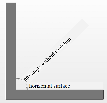
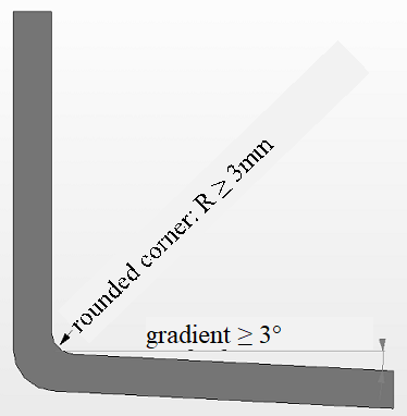
Corners and edges, especially inside corners, can be avoided by rounding them at transitional areas. Surfaces should be as smooth as possible. It is important that additionally, components are designed to prevent liquids from accumulating. Liquids are able to run off surfaces, or be removable in another way. To ensure this, surfaces cannot be horizontal but instead have a gradient of at least 3° (Figure D-1).
|
Hygienically unfavourable construction
|
Hygienically favourable construction
|
|
|
|
|
|
|
Figure: Design of corners and edges
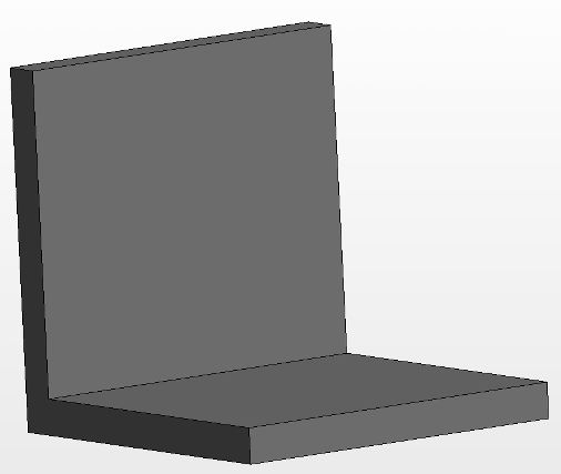
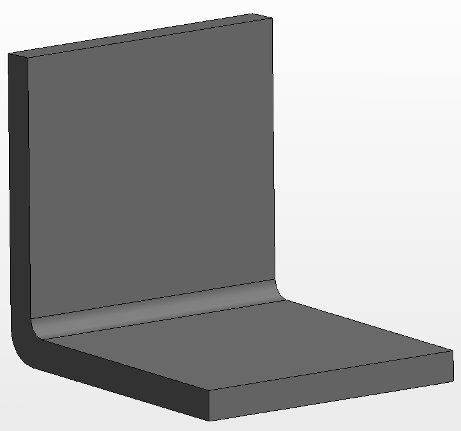
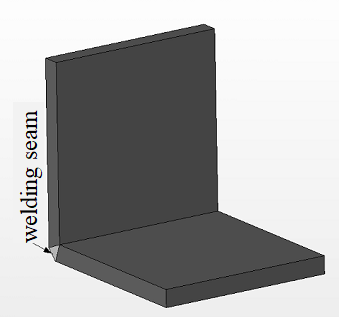
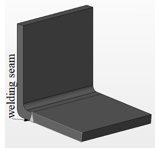
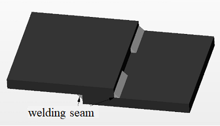
Weld seams at corners and edges
No weld seams can be used in these areas because the risk of cracks forming in them is very high. Microorganisms can them collect and colonize in the cracks and gaps. If weld seams are unavoidable, it is important that they are located away from rounded corners (Figure D-2).
|
Hygienically unfavourable construction
|
Hygienically favourable construction
|
|
|
|
Figure: Material transitions joined by a weld seam
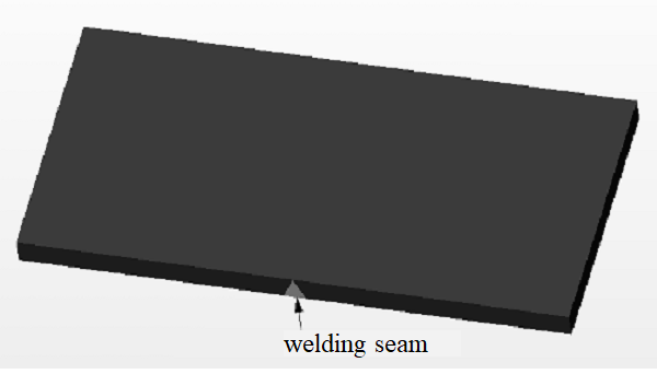
Transitions
If joins were not carried out correctly, there is a risk of undesired contamination occurring because gaps can form in them. To minimize this risk, joins (areas where small pieces of material are fitted to a larger piece) that are unnecessary need to be avoided wherever possible. This can be achieved by using appropriately-shaped large pieces of material. It is important that transition areas also are designed for ease of cleaning. Interrupted weld seams, for example, cannot be cleaned effectively. Therefore, weld seams are always be continuous. Any corners or edges arising in areas where weld seams have been used are rounded (Figure D-3).
|
Hygienically unfavourable construction
|
Hygienically favourable construction
|
|
|
|
Figure: Materials joined by a weld seam
Fixed/separable joins:
To reduce the risk of gaps caused by separable joins such as screw connections, non-separable joins such as weld seams are used if separable joins can be avoided. However, it is important that seams are appropriately welded to prevent microorganisms from collecting. The smoothness, application and position of the weld seam play a major role in this regard.
By adhering to the guidelines and norms concerned with the hygienic design of machines and equipment, cleaning processes can be kept to a minimum. It is important that the design of machinery already is taken into account during planning because it can be extremely difficult to correct constructional errors at a later stage.
ANNEX(informative)Cleaning techniques
Blasting cleaning techniques
Compressed air blasting
Principle: This type of cleaning involves the use of a blast of compressed air. Surfaces are cleaned through the action of various blasting agents which are carried in the compressed air blast and applied at high speed to the object to be cleaned. The energy of impaction removes contamination, debris, corrosion, scale and paint. The method is highly versatile. Typical blasting pressures range between (2000 – 3000) hPa and are adapted to the cleaning process concerned (material of cleaning surface, degree of cleanliness required, etc.). The blasting agent, angle of the jet and selection of an appropriate nozzle are also important aspects to be considered.
Areas of application: Compressed air blasting is suitable for cleaning components and structures of every size and description (although undercuts are difficult to access).
Compressed air blasting cannot generally be utilized to clean sensitive surfaces. The high kinetic energy transferred by the blasting agent impacting onto the surface attacks the surfaces of the components and damages them. Employed in cleanrooms or other controlled environments, the process can result in re-distribution of particulate contamination rather than elimination. Thus removing it locally form the hardware to which it is applied but not removing it from the local environment. It is important that factory compressed air lines have oil or molecular filters and particulate filters in-line.
Typical cleaning category:
Removing particulate contamination: Pre-cleaning
Removing organic contamination: Pre-cleaning
Wet compressed air blasting
Principle: The method is similar to that of compressed air blasting. However, here a liquid is added either in front or behind the nozzle (usually ultra-pure water) to form a jet composed of air, water and a blasting agent. An appropriate rust inhibitor can also be added to the water.
Areas of application: Wet compressed air blasting is used where dust levels need to be kept to a minimum or where sensitive surfaces require a more gentle cleaning process. The method is appropriate for cleaning components and structures of every size and description. The surface to be cleaned is generally covered with slurry which needs to be removed with a jet of air or water after the cleaning is completed.
Typical cleaning category:
Removing particulate contamination: Pre-cleaning
Removing organic contamination: Pre-cleaning
Pressurized fluid blasting
Principle: With this method, a jet of liquid under high pressure (usually clean water) is directed via a nozzle at the component to be cleaned. A solid blasting material, either dry or in suspension, can be added to the fluid to increase the abrasive action. Rust inhibitors can also be supplemented to the water jet.
Areas of application: Pressurized fluid blasting is suitable for cleaning components and structures of every size and description (undercuts are difficult to access). If process parameters are adjusted carefully, individual layers of a coating system can be removed. But the blasted surfaces are generally covered with slurry.
The method is especially suitable for reducing quantities of soluble salts. The high water pressure demands appropriate safety measures.
Typical cleaning category:
Removing particulate contamination: Main/Post cleaning
Removing organic contamination: Pre-cleaning
Low-pressure water jet blasting
Principle: The method is similar to that of compressed air blasting. However, very little water (generally clean water) is added to the blasting agent/air mixture in front of the nozzle, making the process dust-free in the particle range below 50 µm. The amount of water used can be varied, generally between 15 l/h and 25 l/h, and appropriate rust inhibitors can be added. In contrast with compressed air blasting, a surface prepared using this method is initially wet.
Areas of application: The method is suitable for cleaning components and structures of every size and description (undercuts are difficult to access). It is invariably used in cases where dust and water levels need to be kept low.
Typical cleaning category:
Removing particulate contamination: Pre-cleaning
Removing organic contamination: Pre-cleaning
Elutriation blasting
Principle: With elutriation blasting, a fine-grained material dispersed in water or other liquid is blasted at high speed onto the surface to be cleaned. Contrary to wet compressed air blasting, in this case the liquid accelerates the blasting agent. This blasting method differs from the pressurized fluid blasting in its purpose and in a much lower pressure of just a few 1000 hPa (compared to several 10^5 hPa or 10^6 hPa pressure with pressurized fluid blasting). While pressurized fluid blasting is used to remove coatings, rust and scale from surfaces, elutriation blasting is used to clean and finish/micro-finish surfaces simultaneously.
Areas of application: The method is suitable for producing a fine surface profile in cases where low surface roughness is required. The process creates an especially fine and even surface. It is also ideal for removing soluble salts.
Typical applications of elutriation blasting:
Removing scale in precision casting
Micro-deburring
Precision-deburring in thermoplastics
Polishing surfaces
Reinforcing surfaces
Cleaning surgical instruments.
The treated surface is rinsed or sprayed with clean water after blasting in order to remove any adhering blasting agent residues.
Typical cleaning category:
Removing particulate contamination: Pre-cleaning
Removing organic contamination: Pre-cleaning
Centrifugal blasting
Principle: With this process, surfaces are cleaned due to the action of a wide range of blasting agents which are catapulted from fixed, rotating paddle wheels onto the object to be cleaned in a closed system. The blasting material is fed to rotating wheels or blades in such a way so that it is applied evenly and at high speed to the surfaces to be cleaned. The momentum of the impact detaches contamination, deposits, corrosion, scale and coatings.
Areas of application: Centrifugal blasting is used to clean components with accessible surfaces such as metal sheets.
Typical cleaning category:
Removing particulate contamination: Pre-cleaning
Removing organic contamination: Pre-cleaning
Steam blasting
Principle: With steam blasting, water is subjected to pressure and heated to temperatures over 100 °C. The pressurized water expands in a nozzle and the resulting atomized spray is directed at the surface to be cleaned. The high temperature of the jet rapidly heats the component and causes grease and oil to run off. The cleaning action can be enhanced by adding washing agents. Among other things, standard washing agents contain phosphate additives which coat steel parts with a rust-proof film.
Areas of application: Steam blasting is used where especially strong mechanical washing and rinsing actions are required, e.g. to clean the tracks and undercarriages of towing and construction vehicles, floor or wall surfaces, machine tables, etc.
Typical cleaning category:
Removing particulate contamination: Main/Post cleaning
Removing organic contamination: Main/Post cleaning
CO2 pellet cleaning
Principle: The method of cleaning with dry ice pellets has been developed as an alternative to conventional abrasive cleaning and de-coating processes such as pressurized fluid blasting, grinding or polishing with wire brushes.
Dry ice pellets are particles made of solid carbon dioxide which are 1 mm to 6 mm in diameter, 5 mm to 15 mm long and approx. -78.5 °C in temperature. They are obtained by cooling liquid carbon dioxide through expansion to form dry ice which is then compressed and forced through a matrix.
During the cleaning process, the dry ice pellets are accelerated to almost supersonic speed (300 m/s) by a jet of compressed air. On impacting on the surface, the component to be cleaned is rapidly cooled, causing the adhering material to become brittle. The dry ice pellets penetrate the fissured layer of contamination and their high kinetic energy causes it to be “blasted” off the component.
Due to the fact that carbon dioxide sublimes, the debris formed is only made up of the actual contamination present. Compared with pressurized fluid blasting, the component surface is significantly less abraded using this method.
Areas of application: Surfaces treated with conventional abrasive cleaning methods can generally also be cleaned using dry ice pellets, e.g. coatings and most types of coarse contamination.
The method can be utilized on nearly all materials, e.g. metals, rubber, ceramic, stone, plastics, GRP and other materials. If a strong jet is used, stainless steel surfaces are not abraded but brass surfaces are slightly roughened and those of aluminium visibly roughened.
The following types of contamination can be removed: rust, adhesives, resins, oils, grease, wax, bitumen, sealings, paints, coatings, separating agents, PU foams, food residues, cakings, encrustations, plastic residues, soot, slag, quicklime, Teflon, graffiti, glue, algae, moss and many other substances.
Typical cleaning category:
Removing particulate contamination: Main/Post-cleaning
Removing organic contamination: Main/Post cleaning
Accelerated CO2 snow cleaning
Principle: This cleaning method is a further development of the CO2 pellet cleaning. Instead of using the more abrasive CO2 pellets, this process is especially gentle and belongs to the “compressed air blasting” techniques in the “cleaning blasting” group.
Accelerated CO2 snow cleaning describes CO2 cleaning methods where the blasting agent - solid CO2 (dry ice) - is produced from liquid CO2 during the cleaning process and is accelerated (by a second gas). Accelerated CO2 snow cleaning is a dry and solvent-free process which can easily be automated. CO2 snow is produced from liquid carbon dioxide which is normally expanded at atmospheric pressure. The carbon dioxide expands rapidly and cools considerably in the process. As it expands, it changes from liquid CO2 to form a mixture of solid CO2 (dry ice) and gaseous CO2. The dry ice is then blasted onto the surface to be cleaned accelerated by ultrapure nitrogen. Such processes are mainly used for precision cleaning as only tiny dry ice crystals are formed.
Insoluble particles can be removed from a surface through the use of a high-velocity jet of gas. The flow of gas exerts an aerodynamic force on the particles adhering to the surface. The force is proportional to the cross-section of the particle in the direction of the jet. If the aerodynamic drag force of the particle exceeds the adhesive force between the particle and the surface, the particle is detached from the surface and carried away with the flow of gas. The adhesive force - mainly determined by van der Waals, dipole and capillary forces - is dependent upon the diameter of the adhering particle. However, the force of adhesion decreases less rapidly with the particle diameter than the aerodynamic resistibility. This means that very small particles (in the micrometre range) can no longer be removed just by a flow of gas. The presence of CO2 snow particles in the flow of gas enable additional forces to be exerted on adhering contaminant particles though the transfer of momentums. The detached particles are then simply carried away with the high-velocity stream of gas. Tests have shown that both large and very small particles can be removed using CO2 snow cleaning.
Another effect achieved with CO2 snow cleaning is the freezing and fissuring of contamination which can then be removed more easily through momentum transfer.
Liquid CO2 is a suitable solvent for covalent substances. In a state of equilibrium, CO2 is in a gaseous state at room temperature and at atmospheric pressure. However, when a snow particle impacts on a surface, other conditions prevail temporarily. During the short period of impact, a force between the surface and the CO2 particle is exerted which leads to a surface pressure at the point of contact. Pressure and temperature increase at the point of contact and the immediate environment passes into the liquid phase. It is in this phase that organic contamination is dissolved. As soon as the particle rebounds from the surface (conservation of momentum), pressure decreases and the point of contact consolidates again with the dissolved contamination. The latter is thus carried away by the rebounding snow particles and falls where the snow sublimates.
Areas of application: CO2 snow cleaning has a broad scope of usage, ranging from precision cleaning right up to the cleaning of large surface areas of machines and equipment, tools, moulds and plastic and metal components.
It important to note that surfaces can only be effectively cleaned if they can be accessed directly by the CO2 snow jet. Small lightweight components are also difficult to clean because they can be blown away by the jet.
As the method is non-abrasive, it can be utilized to clean highly sensitive surfaces. Organic and inorganic particulate contamination can be removed as well as oil films, grease, fingerprints and flux residues. It is not suitable for removing strongly-adhering encrustations, thick layers of paint or rust.
Typical cleaning category:
Removing particulate contamination: Main/Post-cleaning
Removing organic contamination: Main/Post-cleaning (for thin films)
Mechanical cleaning
Wiping
Principle: In many cases, a surface can simply be wiped clean with the aid of a dry cloth. Soft, non-abrasive cloths can be utilized to remove lightly-adhering contaminants (dust, dirty water, etc.). Rougher cloths, sponges or even steel wool can be used to remove strongly-adhering contamination from robust components. Wiping is generally carried out manually and is best suited for sporadic or once-only cleaning tasks. If a wiping process is performed using a cleaning fluid, the chemical action of the cleaning agent is essentially responsible for the cleaning effect.
In order to detach and remove contaminants with a wiping cloth, the adhesive forces between the contamination and component surface need to be overridden by frictional movements. Solid contamination such as dust particles are then held in the fibres of the cloth due to adhesion whereas liquid contamination is attracted to the fibres due to capillary forces. This enables even thick lubrication films to be removed quickly, albeit not completely. Wiping is especially effective for removing liquid contamination and is therefore also used to dry components. It is important that a wiping cloth is disposed once it become saturated with contaminants.
Areas of application: Wiping without the use of cleaning agents is generally used to remove contamination adhering lightly to delicate surfaces. This is because the process is not very abrasive compared to other techniques. All materials which are not damaged by the chosen cloth or sponge can be cleaned in this way. As a rule of thumb, the material which the cloth or sponge is made of is a lower degree of hardness than the surface or coating of the component to be cleaned.
Wiping is usually carried out by hand and automated equipment is only implemented in exceptional cases. The technique is mainly used in the maintenance or repair of machines, equipment and operating utilities, especially if
the component to be cleaned is very large,
the component cannot be moved,
only specific parts of a pre-assembled device need to be cleaned, or
parts of a device can be damaged if a different cleaning technique or aggressive cleaning agent is used.
Examples of wiping in industrial manufacturing include cleaning optical elements, electrical contacts and preparing surfaces prior to painting.
Typical cleaning category:
Removing particulate contamination: Pre-cleaning
Removing organic contamination: Not suitable
Brushing and sweeping
Principle: The cleaning technique of brushing/sweeping is the purely mechanical wiping off or abrading of generally solid contaminants from a component surface through the action of bristles. Brushes with soft bristles made of plastic or natural fibres are used to remove easily-detachable contamination such as dust. For strongly-adhering contaminants such as oxides, scale or paint, hard stiff bristles made of steel or a similar material is utilized. All materials which are not damaged by the chosen brush or where a minimum degree of surface abrasion is tolerated can be cleaned in this way. The active principle of brushing or sweeping is the mechanical wiping off or abrasion of generally solid contaminants from a component surface.
Areas of application: Brushing/sweeping is frequently used to clean floors or as a fast manual cleaning step.
Typical cleaning category:
Removing particulate contamination: Pre-cleaning
Removing organic contamination: Pre-cleaning
Scraping and abrading
Principle: Scraping or abrading is a mechanical separation technique in which adhering solids are lifted up by a tool placed beneath them and then removed. Scraping/abrading is carried out using a blade or scraper, usually manually or occasionally using pneumatically or electrically driven scraping or abrading tools.
Areas of application: Scraping/abrading is implemented to remove strongly-adhering material residues from essentially smooth surfaces. The technique is typically used to remove paint, glue, resin, cement or scraps of wallpaper or carpet from floors and walls as well as to clean off coats of paints or varnish from equipment and installations. Scraping/abrading is a relatively labour-intensive process which is generally carried out by hand.
Typical cleaning category:
Removing particulate contamination: Pre-cleaning
Removing organic contamination: Pre-cleaning
Grinding
Principle: Grinding is the removal of superficial contamination by a grinding tool, usually rotating grinding discs or high-speed circular grinding belts. Grinding is capable of removing strongly-adhering contaminants such as scale, oxides, rust, coatings or paints quickly and effectively. However, a certain amount of base material is also abraded. If this cannot be tolerated, a different cleaning technique need to be selected.
Areas of application: The grinding discs used are made of grains of hard material (e.g. Silicon carbide) embedded in a bonding material (e.g. Ceramic compounds). The selection of the grain and bonding material are decisive for the grinding process.
Typical cleaning category:
Removing particulate contamination: Pre-cleaning
Removing organic contamination: Pre-cleaning
Beating off
Principle: With this technique, contamination is beaten off. A suitable beating tool transfers an impulse to the component to be cleaned which experiences a moment of rapid acceleration or starts to vibrate. Contaminants can be removed in this way if the mass inertia of the contamination exceeds the forces of adhesion exerted between the component and contamination.
Areas of application: Beating off is a pre-cleaning technique which is used to remove large quantities of contamination at low equipment cost within a very short period of time. However, a high degree of cleanliness cannot be achieved on this way. It is therefore mainly used as a preliminary PRE-cleaning step prior to subsequent cleaning processes.
Beating off is generally a manual process using simple beating tools (e.g. hammers). In casting processes, which are designed for high piece numbers, beating off is partially automated.
Typical cleaning category:
Removing particulate contamination: Pre-cleaning
Removing organic contamination: Not suitable
Fluidic cleaning
Washing and rinsing
Principle: Cleaning with the aid of solvent cleaning agents often involves subsequent rinsing in order to remove the detached/emulsified contamination as well as the active ingredients of the solvent cleaning agent itself, e.g. tensides and emulsifiers, from the component surface. This prevents contaminants from being transferred to the next cleaning step or causing re-contamination in a subsequent drying process. In contrast with cleaning, the rinsing process does not remove or emulsify contaminants but instead dilutes the contamination dissolved or emulsified in the cleaning solvent and the active ingredients of the cleaning agent to an acceptable degree.
Areas of application: Rinsing processes are principally used to achieve improved cleanliness levels after cleaning with aqueous fluids. Especially in galvanics, complex multi-step rinsing processes are implemented. Tap water is generally utilized but in cases where cleanliness requirements are very high, desalinated (e.g. distilled) water is used.
Typical cleaning category:
Removing particulate contamination: Main/Post-cleaning
Removing organic contamination: Main/Post-cleaning
Blowing off cleaning
Principle: With this cleaning technique, surfaces are cleaned by the action of a jet of air which is directed at an object at high speed via a nozzle. The air jet exerts an aerodynamic force on the particle adhering to the surface. The force is proportional to the cross-section of the particle in the direction of the jet. If the aerodynamic resistance of a particle exceeds the adhesive force between the particle and the surface, the particle is detached from the surface and carried away with the flow of air. Especially dry, loosely-adhering contaminants such as dust can be removed effectively. Very small particles (in the micrometre range) can no longer be removed just by using a high-speed jet of air. Liquid or paste-like contamination such as lubricants and oils can also be partially removed if higher pressures are used. However, a thin film of dirt remains on the component which needs to be removed in a subsequent cleaning process. A further use of blowing is to dry components after cleaning with cleaning liquids.
Areas of application: If only dry contamination is present, good cleaning results can be achieved for particles larger than 50 µm. Liquid or paste-like contamination can also be partially removed using higher pressures (e.g. by using supersonic (Venturi) nozzles). However, a thin film of dirt remains on the component which needs to be removed in a subsequent cleaning process. A further use of blowing is to dry components after fluidic cleaning.
Typical cleaning category:
Removing particulate contamination: Pre-cleaning
Removing organic contamination: Not suitable
Suction cleaning
Principle: With suction cleaning, a suction nozzle is placed above the component surface to be cleaned. A pump connected to the nozzle creates a negative pressure which causes air to flow away from the component surface. The airflow exerts an aerodynamic force on the particles adhering to the surface. The force is proportional to the velocity of the incident airflow and the cross-section of the particle in the direction of flow. If the aerodynamic resistance of the particle exceeds the adhesive force between the particle and the surface, the particle is detached from the surface and carried away with the airflow. Suction cleaning is especially suitable for removing dry contamination such as dust particles, grinding dust and chippings. If liquid or paste-like contamination is present, the adhesive forces concerned are generally too high and the process is ineffective. The technique is also usually unsuitable for removing very small particles (in the micrometre range) because the maximum attainable negative pressure of 1 bar is too low to produce an adequately strong air jet.
Areas of application: Suction cleaning is used in environments where high dust levels can occur because dust particles from substances such as flour, sugar, starch, grain or even aluminium can form potentially explosive mixtures in the ambient air.
Typical cleaning category:
Removing particulate contamination: Pre-cleaning
Removing organic contamination: Not suitable
Ultrasonic cleaning
Principle: With ultrasound cleaning, the parts to be cleaned are suspended in a bath filled with a suitable cleaning agent. Ultrasound waves are created in the cleaning bath via oscillators located at the base or side walls and spread longitudinally through the cleaning agent. Due to the fact that a pressure below vapour pressure prevails during the oscillation phase, vapour-filled bubbles known as cavitation bubbles form on the surface of the parts to be cleaned. These then implode as a result of the higher pressure in the next phase and create implosion pressures of approx. 10^6 hPa. The momentary high implosion pressures occurring cause contamination to be blasted off the component surface and dissolve or disperse into the cleaning fluid. After cleaning, most components need to be rinsed and dried.
Areas of application: Ultrasound cleaning achieves extremely high quality results within a very short space of time. The strong mechanical action of cavitation caused by the ultrasound waves ensures that even complex-shaped components, crevices and drill holes are cleaned effectively. Despite this, it is still a gentle cleaning technique which can be used to clean delicate surfaces without damaging them (depending on the material).
Ultrasound is especially utilised to clean precision engineering components, medical (particularly surgical) instruments, record matrices, optical lenses (especially before hardening processes), ophthalmic lenses and frames, glass receptacles, dentures, jewellery, cutlery, camera housings, TV tubes before coating, electrical modules, completed circuit boards, components and materials before galvanisation processes, radioactively contaminated objects and much more.
Typical cleaning category:
Removing particulate contamination: Main/Post-cleaning
Removing organic contamination: Main/Post-cleaning
Chemical cleaning
General principle of chemical cleaning
Chemical cleaning is a technique where a cleaning agent reacts with the contamination present to remove it. The cleaning agent then either evaporates or can be easily removed.
Etching and leaching
Principle: As a rule, metallic and plastic surfaces are etched and leached using aggressive chemicals, mainly acids or leaches. This enables oxides such as rust or metallic compounds to be removed from surfaces.
To treat steel, acid etchants such as hydrochloric acid, sulphuric acid and nitric acid are generally used. Aluminium and zinc materials can be etched both in acid and alkaline solutions, e.g. caustic soda. However, after alkaline etching processes, an acid often are used to remove loosely adhering leaching residues from the surface.
Etching acids usually contain organic inhibitors to limit etching as much as possible to the oxidic contamination and to minimize damage to the base material. If tensides are added, etching baths also have limited degreasing properties.
Areas of application: Removal of paints, adhesives or other organic coatings from a range of surfaces.
Typical cleaning category:
Removing particulate contamination: Main/Post-cleaning
Removing organic contamination: Main/Post-cleaning
Chemical reaction
Principle: Specifically selected chemicals are used in a targeted way to convert contamination through a chemical reaction into other compounds which are either volatile or easy to remove.
Areas of application: With this principle, surfaces can be descaled, for example, by using acidic aqueous solutions. Lime (calcium carbonate) which is insoluble in water is converted by the acid components into a water-soluble salt which remains in solution after the conversion process.
Drain cleaners are mixtures of chemicals which remove blockages in drain pipes by way of a chemical reaction (degradation).
Typical cleaning category:
Removing particulate contamination: Main/Post-cleaning
Removing organic contamination: Main/Post-cleaning
Solvent cleaning
Detaching and stripping
Principle: With this technique, contamination is removed by dissolving it in an organic solvent. Surfactants enhance the removal of small particles from surfaces by altering the associated interactive forces between the particle and substrate, primarily by adsorption of the surfactant on both the particle surface as well as the substrate surface.
The type of cleaning agent used mainly depends on the type of contamination to be removed and the component to be cleaned. Both aqueous cleaning agents (acid, alkaline or neutral) and organic solvents can be implemented.
Areas of application: Organic solvents are often combined with other cleaning methods to improve the cleaning effect (see wiping).
Additionally, the use of solvents assists drying processes after components have been cleaned. Standard cleaning agents include chlorinated hydrocarbons such as trichloroethylene (Tri) and perchloroethylene (Per); their use involves adherence to strict regulations due to health hazards. In addition to this, fire and explosion hazards are taken into consideration.
Organic solvents can also be utilized to remove soluble layers such as films of glue and coating layers from component surfaces.
Typical cleaning category:
Removing particulate contamination: Main/Post-cleaning
Removing organic contamination: Main/Post-cleaning
Thermal cleaning
General principle of thermal cleaning
Thermal cleaning is a technique that principally removes contamination through the action of heat.
Evaporating
Principle: Liquid or molecular contamination present on the surface of a component is removed by converting it into a vaporous state, thus neutralizing the adhesive forces between the contaminant and component surface. For solvent removal this is a thorough drying process. In contrast with vaporization, evaporation takes place at temperatures below boiling point. Instead of increasing the temperature the removal efficacy can also be improved by application of vacuum.
Areas of application: Evaporating is a common drying method performed after aqueous cleaning processes. The cleaning liquid is vaporized or evaporates, respectively, but the detached substances remain on the surface of the component, e.g. detached contamination such as salts, metals or active bath ingredients such as tensides. This results in drying spots which can be reduced by rinsing the components thoroughly before drying.
The removal of molecular contamination from space hardware is typically performed by a vacuum bake to allow for efficient cleaning under moderate thermal exposure.
Typical cleaning category:
Removing particulate contamination: Not suitable
Removing organic contamination: Main/Post-cleaning
Scarfing
Principle: The surface to be cleaned is torched with a hot flame (for example, acetylene flame at 3200 °C). In the process, organic contamination such as grease and oil is vaporized or charred and metal oxides reduced to metal, thus decreasing their adhesion to the surface.
Areas of application: Scarfing is mainly used to prepare surfaces before applying a new coat, such as coverings to concrete floors or anti-corrosive coatings to steel constructions. Scarfing is also utilized in the heavy equipment industry (to clean tanks) and in shipbuilding.
Scarfing is not suitable for all types of components because heating can result in undesired effects such as the deformation of thin parts or changes in material structure.
Typical cleaning category:
Removing particulate contamination: Not suitable
Removing organic contamination: Main-cleaning
Decomposing
Principle: Components are placed in heatable cleaning ovens and the contamination present on the surface is decomposed at temperatures between 300 °C und 500 °C into organic and inorganic constituents which are easier to remove. But the component then requires further treatment in order to remove the charred residual contamination.
Areas of application: The process is used to remove paint and grease from components of all shapes.
Thermal decomposition is not suitable for all types of components because heating can result in undesired effects such as the deformation of thin parts or changes in material structure.
Typical cleaning category:
Removing particulate contamination: Not suitable
Removing organic contamination: Main-cleaning
Special cleaning
Hot vacuum purge
Principle: With the hot vacuum purge process, the components to be cleaned are placed in a vacuum chamber and subsequently heated using a radiant heater. Process temperature and pressure are selected in such a way so as to ensure that the contamination present vaporises. The technique is only suitable for removing liquid contamination, especially oils and organic contamination. Particulate and other solid or paste-like contamination can generally not be vaporised. The contamination vapour is then removed by a prepump and vacuum pump and converted back to a liquid in a condenser.
A particular advantage of the process is that components of all shapes and sizes can be cleaned effectively either as individual parts, subassemblies or even complete machines without needing to be dismantled. Due to the time required to evacuate the chamber and heat the respective components, process times for hot vacuum purging range between 5 and 15 minutes. Energy consumption is relatively high as a result of the need to heat the components. A disadvantage to this method is the heating that takes place in the chamber. All parts are heated up completely over a longer period. This leads to thermal expansion as well as thermal strain and therefore stress cracks in treated parts/equipment can occur.
Typical cleaning category:
Removing particulate contamination: Not suitable
Removing organic contamination: Main-/Post-cleaning
Hot N2 purge
Principle: With the hot N2 purge process, the components to be cleaned are placed in a chamber and hot, dry ultra-pure N2 is passed over the top of the hardware. The technique is only suitable for removing liquid contamination, especially oils and organic contamination. Particulate and other solid or paste-like contamination cannot be removed.
A particular advantage of the process is that components of all shapes and sizes can be cleaned effectively either as individual parts, subassemblies or even complete machines without needing to be dismantled or have a specialist thermal vacuum chamber. A disadvantage to this method is the heating that take place in the chamber. All parts are heated up completely over a longer period. This lead to thermal expansion as well as thermal strain and therefore stress cracks in treated parts/equipment can occur.
Typical cleaning category:
Removing particulate contamination: Not suitable
Removing organic contamination: Main/Post-cleaning
Plasma Chamber cleaning
Principle: Plasma Chamber cleaning is a dry, non-contact, non-abrasive cleaning technique capable of producing excellent organic cleaning results. However, this is only possible if the layers of contamination present are very thin. Inorganic thin films or particles cannot be cleaned off. Consequently, Plasma Chamber cleaning is generally used as a final precision cleaning step in multi-step cleaning sequences.
Plasma Chamber is a gaseous mixture composed of atoms, molecules, ions and free electrons. As a result of a chemical reaction with the free radicals, organic contamination is usually converted into water vapour and carbon dioxide.
Areas of application: Typical applications are the cleaning of wafers, bumpers, piston rings, gears, power tools, hypodermic needles, plastic lenses, switching contacts and electronic components.
Typical cleaning category:
Removing particulate contamination: Not suitable
Removing organic contamination: Post-cleaning
UV-light cleaning
Principle: This is a precision cleaning technique which can be used to achieve very high cleaning results. The components to be cleaned are placed in a closed chamber with an atmosphere containing either O3 molecules or an aqueous solution of H2O2. On irradiating the atmosphere with UV light, free oxygen radicals are split from the O3 or H2O2 molecules which then react with the organic contamination to form CO2.
The technique is most effective if only very thin layers of organic or carbonic contamination require removal. Particles, salts or ionic contamination cannot be cleaned off. Additionally, a range of organic contaminants and products of decay such as carboxylic acid cannot be removed. If O3 is utilized as a solvent, the process is dry. If on the other hand H2O2 is used, the process is wet.
Areas of application: UV-light cleaning is used, for example, to clean off organic contamination from semiconductor components.
Typical cleaning category:
Removing particulate contamination: Not suitable
Removing organic contamination: Main-/Post-cleaning
LASER beam cleaning
Principle: Cleaning with the aid of a laser beam is a non-contact and gentle technique. If the process is well controlled, clearly delineated areas can be cleaned and layers of a specific thickness removed. Only a very thin layer of the base material is exposed to the influence of heat.
Areas of application: Examples of use up to now include the removal of paints and coatings from metallic components, especially in the aircraft industry, the removal of photo or solder masks from circuit boards, cleaning paintings and works of art, precision paint stripping for selective galvanic surface coating processes and also for cleaning gravure cylinders. Depending on the equipment and coating concerned, the speed of the laser beam cleaning process can exceed 10 m²/h.
Typical cleaning category:
Removing particulate contamination: Post-cleaning
Removing organic contamination: Post-cleaning
Supercritical CO2 Cleaning
Principle: CO2 snow is ideally suited for removing particulate contamination from surfaces. However, in order to clean e.g. drill holes, it is also essential that oil residues are removed efficiently. The use of supercritical CO2 as a solvent fulfils this requirement. The CO2 injector cleaning tool combine both of these effective methods, ensuring that drill and blind holes are cleaned rapidly and efficiently using a dry process.
Cleaning is performed in the following steps:
Injection needle is introduced into the drill hole
Drill hole is sealed off
Venting with supercritical CO2 (>31°C, >78000 hPa)
Flushed with supercritical CO2 (to remove oil)
Blasted with CO2 snow (to remove particles and chips)
Areas of application: The cleaning of complex geometrical shapes, such as drill holes, blind holes with high facet ratios and very small parts, is very difficult. Here, bore chips, particles and machining oil residues often need to be removed within very short cycle times.
The solvent power of the supercritical CO2 is adjusted according to the type and amount of oil to be removed by altering the temperature and pressure of the medium as well as the number of flushing cycles.
Depending on the contamination level of the drill hole, the cleaning process is completed within a few seconds. In consequence and also due to the fact that subsequent processes such as drying are no longer required, the technique can be simply integrated into large scale productions.
The advantages of the CO2 snow cleaning technique can also be used for substrates that have a very uneven discontinuous surface with holes, undercuts, etc.
Typical cleaning category:
Removing particulate contamination: Main-/Post-cleaning
Removing organic contamination: Main-/Post-cleaning
Liquid Peel Cleaning
Principle: A liquid (e.g. ESO developed XL Clean 5; a polyurethane dispersion in water of white coloration) is poured or sprayed onto the surface to be cleaned, allowed to dry (3hr approx.), and then the resulting film is stripped off from the surface. This remove organic residues and small particles from the surface. Depending on the solvent used the method can be harsh on some coated surfaces. The residue left depends on the exact product used and some suppliers are reluctant to reveal the solvent used, however the solvent does not always be organic (e.g. XL Clean 5 uses water).
Areas of application: The method is primarily used for the cleaning of optical surfaces. Commercial products are available for amateur astronomers for small telescopes (1m) but the method has been developed and used for very large telescopes (10m). The method also has the advantage that the film can be left on and used as a protective cover during any storage or transport.
Typical cleaning category:
Removing particulate contamination: Main cleaning
Removing organic contamination: Main cleaning
ANNEX(informative)Contamination detection techniques
Particulate contamination
General
More detailed guidelines for method selection and analytical techniques are given in ISO 14644-9: 2012 Cleanrooms and associated controlled environments - Part 9: Classification of surface cleanliness by particle concentration.
Assessment matrix
To detect particles quantitatively and meaningfully on surfaces, a method has to analyze and combine several image fields automatically in order to be able to analyze the particle charge on larger interconnected surfaces. In the case of microscopes, this is achieved using motorized sample tables combined with image analysis software, which can detect particles via contrast and the determination of threshold values. Based on the following criteria, Table F-1 assesses the systems and combinations thereof used most frequently for automated particulate analysis (comprising microscopic and spectroscopic methods):
Detectable particle characteristics:
Particle detection limit (lateral resolution): What is the lateral resolution limit of the method?
Minimum detectable particle size
Morphology/shape analysis: Which morphological particle characteristics can be detected?
Length
Width
Largest and smallest dimensions
Diameter
Aspect ratio (e.g. fibre-type)
3D information: Can volume characteristics also be ascertained?
Spherical
Flat
Height
Size distribution and determination of concentration: Is it possible to ascertain the size distribution and concentration of particles?
Radius distribution
Volume distribution
Count distribution
Determination of position: Can the position of the particles detected be ascertained?
Relevant and interesting for later use, complementary analysis method (»correlative method«)
Material analysis: Can the chemical composition of the particles (complementary) be determined?
Element contents
Chemical groups
Phase composition
Surface chemistry
Influence on substrate:
Independent of the surface: Are there any special requirements regarding the substrates to be inspected?
Size
Material
Roughness
Optical features such as transparency, reflecting surfaces, etc.
Influence on the surface: Does the analysis influence the substrate to be inspected?
Roughness, porosity, waviness, etc.
Material
Full-surface analysis: Do the devices used in the method allow full-surface analysis?
Measuring times in dependence upon substrate size and resolution
Control and software (automatability)
Method:
Portability: Can the device used portable?
Size
Installation and start-up times
Accessibility: Which geometries can be analyzed directly?
Shape of the sample
Planar, flat samples
Testing speed: Is it economically feasible to carry out full-surface inspection?
Measuring times
Inline inspection
100 % inspection
Flexibility: Are there any conditions which the device has to fulfil?
Test environment (e.g. cleanroom, vacuum)
Anti-vibration mounts
Operator influence:
Is the method easy for the operator to use? Are there any sources of operator error which can affect results?
Table: Comparison of different direct particle detection methods
|
Method
|
detectable particulate properties
|
substrate
|
method
| ||||||||||||||
|
particle detection limit
|
morphology/shape analysis
|
3d-information
|
size distribution
|
concentration determination
|
Position determination
|
material analysis
|
Independent of the surface (roughness etc.)
|
influence on the surface (roughness etc.)
|
100% Inspection
|
mobility
|
accessibility
|
Testing speed
|
flexibility
|
operator-influence
| |||
|
visual inspection |
25 µm
|

|

|

|

|

|

|

|

|

|

|

|

|

|

|
||
|
light microscope(with image processing) |
1,0 µm
|

|

|

|

|

|

|

|

|

|

|

|

|

|

|
||
|
glancing light(with image processing) |
1,0 µm
|

|

|

|

|

|

|

|

|

|

|

|

|

|

|
||
|
(VP)SEM-EDS(with image processing) |
0,01 µm
|

|

|

|

|

|

|

|

|

|

|

|

|

|

|
||
|
FIB |
0,01 µm
|

|

|

|

|

|

|

|

|

|

|

|

|

|

|
||
|
TEM |
0,05 nm
|

|

|

|

|

|

|

|

|

|

|

|

|

|

|
||
|
atomic force microscopy (e.g. AFM)(with image processing) |
0,01 µm
|

|

|

|

|

|

|

|

|

|

|

|

|

|

|
||
|
camera systems(with image processing) |
> 25 µm
|

|

|

|

|

|

|

|

|

|

|

|

|

|

|
||
|
particulate flatbed scanners(with image processing) |
> 10 µm
|

|

|

|

|

|

|

|

|

|

|

|

|

|

|
||
|
»Particle Fall-Out«-Photometer (PFO) |
> 5 µm
|

|

|

|

|

|

|

|

|

|

|

|

|

|

|
||
|
computer tomography |
> 1 µm
|

|

|

|

|

|

|

|

|

|

|

|

|

|

|
||
|
scattered light surface scanner(for monocrystalline wafers and masks) |
0,05 µm
|

|

|

|

|

|

|

|

|

|

|

|

|

|

|
||
|
Legend: |
|||||||||||||||||
|

|
|
highly suitable |
|||||||||||||||
|

|
|
partially suitable |
|||||||||||||||
|

|
|
not suitable |
|||||||||||||||
Chemical molecular contamination
More detailed guidelines for method selection and analytical techniques are given in ISO 14644-10:2013 Cleanrooms and associated controlled environments - Part 10: Classification of surface cleanliness by chemical concentration. A common process to identify and quantify molecular contamination via infrared spectroscopy is given in ECSS-Q-ST-70-05C.
Microbiological contamination
More detailed guidelines for method selection and analytical techniques are given in ECSS‐Q‐ST‐70‐55 Space product assurance - Microbial examination of flight hardware and cleanrooms.
ANNEX(informative)Witness sample design
Example witness sample design
The specified test sample geometry is according to Figure G-1.
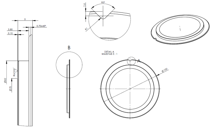
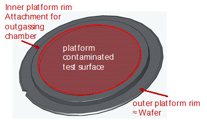 Figure: Test sample geometry to assess the cleaning efficacy of a certain cleaning technique (left) and composition of the test sample surface (right)
The inner circle of the test sample shown in Figure G-1 (right) is contaminated for the cleaning process and verification concept and analysed for particulate, microbiological and organic contamination. It is important that the witness sample design accommodates the functionality of the selected equipment for the determination of the contamination. On the example of Figure G-1 the witness plate can be used for direct particulate analysis (SEM, light microscopy), direct chemical analysis (FTIR, thermal desorption GC/MS) and direct microbiological contamination analysis (direct incubation). Additionally any kind of indirect analysis is possible. The witness sample design, based on 4 inches diameter also allowed the use of standard semiconductor storage equipment for maintenance of cleanliness.
ANNEX(informative)Examples for cleanliness classification
Particles
Classification system
Selected SCP classes for cleanrooms and associated controlled environments are shown in Table H-1.
Table: Selected SCP classes for cleanrooms and associated controlled environments
|
SCP Class
|
Particle size
| ||||||||
|
≥ 0,05 µm
|
≥ 0,1 µm
|
≥ 0,5 µm
|
≥ 1 µm
|
≥ 5 µm
|
≥ 10 µm
|
≥ 50 µm
|
≥ 100 µm
|
≥ 500 µm
| |
|
SCP Class 1
|
(200)
|
100
|
20
|
(10)
|
|
|
|
|
|
|
SCP Class 2
|
(2000)
|
1000
|
200
|
100
|
(20)
|
(10)
|
|
|
|
|
SCP Class 3
|
(20000)
|
10000
|
2000
|
1000
|
(200)
|
(100)
|
|
|
|
|
SCP Class 4
|
(200000)
|
100000
|
20000
|
10000
|
2000
|
1000
|
(200)
|
(100)
|
|
|
SCP Class 5
|
|
1000000
|
200000
|
100000
|
20000
|
10000
|
2000
|
1000
|
(200)
|
|
SCP Class 6
|
|
(10000000)
|
2000000
|
1000000
|
200000
|
100000
|
20000
|
10000
|
2000
|
|
SCP Class 7
|
|
|
|
10000000
|
2000000
|
1000000
|
200000
|
100000
|
20000
|
|
SCP Class 8
|
|
|
|
|
|
10000000
|
2000000
|
1000000
|
200000
|
|
Units in particles per square metre
| |||||||||
Examples for cleaning efficacy
Examples of cleaning efficacies on different substrates are shown in Table H-2.
Table: Examples of cleaning efficacies on different substrates
|
Material
|
Run
|
Cleaning efficacies for the particle sizes
| |||
|
≥ 1 µm
|
≥ 5 µm
|
≥ 10 µm
|
≥ 50 µm
| ||
|
Aluminium
|
1st
|
99,411%
|
99,972%
|
99,964%
|
100,000%
|
|
2nd
|
97,706%
|
99,941%
|
100,000%
|
100,000%
| |
|
Ti-6Al-4V
|
1st
|
99,967%
|
99,989%
|
100,000%
|
100,000%
|
|
2nd
|
99,871%
|
99,951%
|
99,970%
|
100,000%
| |
|
Al Alodine 1200
|
1st
|
99,987%
|
100,000%
|
100,000%
|
100,000%
|
|
2nd
|
99,990%
|
99,989%
|
100,000%
|
100,000%
| |
|
Al black anodized
|
1st
|
100,000%
|
100,000%
|
100,000%
|
100,000%
|
|
2nd
|
100,000%
|
100,000%
|
100,000%
|
100,000%
| |
|
Stainless Steel AISI 304
|
1st
|
100,000%
|
100,000%
|
100,000%
|
100,000%
|
|
2nd
|
100,000%
|
100,000%
|
100,000%
|
100,000%
| |
|
3rd
|
100,000%
|
100,000%
|
100,000%
|
100,000%
| |
Example for reporting of cleaning efficacy :
E[(sCO2) – (A, Ag@>1µm, SCP 8) – (Ti-6Al-4V, Ra0,5) – (D, SEM)] = 99,967%
Cleaning technique: CO2 snow
Contaminant species: Non-viable, Silver particles > 1µm size corresponding to SPC 8
Substrate material: Ti-6Al-4V with surface roughness Ra = 0,5
Analysis method: Direct analysis, SEM
Relative cleaning efficacy: 99,967%
Molecular contamination
Classification system
The classification system for molecular contamination according to ISO 14644-8: ISO-SCC classes is shown in Table H-3.
Table: Overview of ISO SCC molecular contamination classes
|
ISO-SCC class
|
Concentration(g/m2)
|
Concentration(ng/m2)
|
Concentration(ng/cm2)
|
|
0
|
100
|
109
|
105
|
|
-1
|
10-1
|
108
|
104
|
|
-2
|
10-2
|
107
|
103
|
|
-3
|
10-3
|
106
|
102
|
|
-4
|
10-4
|
105
|
101
|
|
-5
|
10-5
|
104
|
100
|
|
-6
|
10-6
|
103
|
10-1
|
|
-7
|
10-7
|
102
|
10-2
|
|
-8
|
10-8
|
101
|
10-3
|
|
-9
|
10-9
|
100
|
10-4
|
|
-10
|
10-10
|
10-1
|
10-5
|
|
-11
|
10-11
|
10-2
|
10-6
|
|
-12
|
10-12
|
10-3
|
10-7
|
Examples for cleaning efficacy
Examples of cleaning efficacies on different substrates are shown in Table H-4.
Table: Examples of cleaning efficacies on different substrates
|
Material
|
Toluene
|
DMP
|
Hexadecane
|
PDMS
|
|
Aluminium
|
97%
|
98%
|
99%
|
99%
|
|
Ti-6Al-4V
|
98%
|
96%
|
98%
|
98%
|
|
Al Alodine 1200
|
94%
|
98%
|
97%
|
99%
|
|
Al black anodized
|
92%
|
99,9%
|
99%
|
97%
|
|
Stainless Steel AISI 304
|
98%
|
98%
|
99%
|
99%
|
Example for reporting of cleaning efficacy :
E[(sCO2) – (C, PDMS, SCC 7) – (Ti-6Al-4V, Ra0,5) – (I, TD-GC/MS)] = 98 %
Cleaning technique: CO2 snow
Contaminant species: Chemical, Polydimethylsiloxane at a level corresponding to SCC 7
Substrate material: Ti-6Al-4V with surface roughness Ra = 0,5
Analysis method: Indirect analysis, Thermal Desorption and subsequent analysis by Gas Chromatography and Mass Spectroscopy
Relative cleaning efficacy: 98 %
ANNEXBibliography
|
ECSS-S-ST-00
|
ECSS system – Description, implementation and general requirements
|
|
ECSS-Q-ST-70-05
|
Space product assurance - Detection of organic contamination of surfaces by infrared spectroscopy
|
|
ECSS-Q-ST-70-50
|
Space product assurance - Particles contamination monitoring for spacecraft systems and cleanrooms
|
|
DIN EN ISO 14159:2004
|
Hygiene requirements for the design of machinery
|
|
DIN EN 1672-2:2005
|
Food processing machinery – Basic concepts –Part 2: Hygiene requirements
|
|
ISO 14644-1: 2015
|
Cleanrooms and associated controlled environments - Part 1: Classification of air cleanliness.
|
|
ISO 14644-8: 2013
|
Cleanrooms and associated controlled environments - Part 8: Classification of air cleanliness by chemical concentration (ACC)
|
|
ISO 14644-9: 2012
|
Cleanrooms and associated controlled environments - Part 9: Classification of surface cleanliness by particle concentration
|
|
ISO 14644-10: 2013 |
Cleanrooms and associated controlled environments - Part 10: Classification of surface cleanliness by chemical concentration
|
|
ISO 14698-1:2003 |
Cleanrooms and associated controlled environments -- Biocontamination control - Part 1: General principles and methods
|