
Space engineering
Radio frequency and modulation
Foreword
This Standard is one of the series of ECSS Standards intended to be applied together for the management, engineering and product assurance in space projects and applications. ECSS is a cooperative effort of the European Space Agency, national space agencies and European industry associations for the purpose of developing and maintaining common standards. Requirements in this Standard are defined in terms of what shall be accomplished, rather than in terms of how to organize and perform the necessary work. This allows existing organizational structures and methods to be applied where they are effective, and for the structures and methods to evolve as necessary without rewriting the standards.
This Standard has been prepared by the ECSS-E-ST-50-05C Working Group, reviewed by the ECSS Executive Secretariat and approved by the ECSS Technical Authority.
Disclaimer
ECSS does not provide any warranty whatsoever, whether expressed, implied, or statutory, including, but not limited to, any warranty of merchantability or fitness for a particular purpose or any warranty that the contents of the item are error-free. In no respect shall ECSS incur any liability for any damages, including, but not limited to, direct, indirect, special, or consequential damages arising out of, resulting from, or in any way connected to the use of this Standard, whether or not based upon warranty, business agreement, tort, or otherwise; whether or not injury was sustained by persons or property or otherwise; and whether or not loss was sustained from, or arose out of, the results of, the item, or any services that may be provided by ECSS.
Published by: ESA Requirements and Standards Division
ESTEC, P.O. Box 299,
2200 AG Noordwijk
The Netherlands
Copyright: 2011 © by the European Space Agency for the members of ECSS
Change log
|
ECSS-E-50-05A
|
First issue
|
|
ECSS-E-50-05B
|
Never issued
|
|
ECSS-E-ST-50-05C
|
Second issue
|
|
ECSS-E-ST-50-05C Rev. 1
|
Second issue revision 1
|
|
ECSS-E-ST-50-05C Rev. 2
|
Second issue revision 2
|
Introduction
This Standard contains requirements to ensure the following:
Compatibility of frequency usage and modulation schemes between space agencies' spacecraft and Earth stations for the Space Operation, Space Research and Earth Exploration-Satellite services.
Compatibility between the spacecraft and the networks that they interact with, as far as possible.
Standardization of frequency usage and modulation schemes within the space projects.
Conformity of spacecraft and Earth station parameters to international radio regulatory provisions (Radio Regulations of the International Telecommunication Union (ITU)) and with national regulatory provisions (e.g. national frequency plans).
Selection of the appropriate parameters of spacecraft and Earth stations that are listed in advance of their use, thus enabling coordination with other interested parties.
Optimization of the frequency usage and modulation schemes within the above limitation.
Scope
This Standard defines the radio communication techniques used for the transfer of information between spacecraft and Earth stations in both directions, and for the tracking systems used for orbit determination. It includes the following:
frequency allocation, assignment and use;
requirements on transmitted signals concerning, for example, spectral occupation, RF power levels, protection of other radio services;
definition of the permissible modulation methods and parameters;
specification of the major technical requirements relevant for the interface between spacecraft and Earth stations;
operational aspects, such as acquisition;
cross-support.
This Standard is applicable to all spacecraft supported by Earth stations and to all controlled Earth stations operating in the Space Operation, Space Research and Earth Exploration-Satellite services as defined in the ITU Radio Regulations.
Other space telecommunication services are not covered in this issue.
All requirements in this Standard are equally applicable to both the customer and the supplier with exception of clauses 4.3.1 and 4.3.2 which are applicable to the customer only.
Further provisions and guidance on the application of this Standard can be found, respectively, in ECSS-E-ST-50 "Communications", and in the handbook ECSS-E-HB-50A "Communications guidelines".
ECSS-E-ST-50 defines the principle characteristics of communication protocols and related services for all communication layers relevant for space communication (physical- to application-layer), and their basic relationship to each other. The handbook ECSS-E-HB-50 provides information on specific implementation characteristics of these protocols in order to support the choice of a certain communications profile for the specific requirements of a space mission. Users of the present standard are invited to consult these documents before taking decisions on the implementation of the present one.
This Standard may be tailored for the specific characteristics and constraints of a space project in conformance with ECSS-S-ST-00.
Normative references
The following normative documents contain provisions which, through reference in this text, constitute provisions of this ECSS Standard. For dated references, subsequent amendments to, or revisions of any of these publications, do not apply. However, parties to agreements based on this ECSS Standard are encouraged to investigate the possibility of applying the most recent editions of the normative documents indicated below. For undated references the latest edition of the publication referred to applies.
|
ECSS-S-ST-00-01
|
ECSS system – Glossary of terms
|
|
ECSS-E-ST-10-03
|
Space engineering – Testing
|
|
ECSS-E-ST-50
|
Space engineering – Communications
|
|
ECSS-E-ST-50-01
|
Space engineering – Space data links - Telemetry synchronization and channel coding
|
|
ITU/RR:2004 ,
|
ITU Radio Regulations
|
Terms, definitions and abbreviated terms
Terms from other standards
For the purpose of this Standard, the terms and definitions from ECSS-S-ST-00-01 and ECSS-E-ST-50 apply.
Terms specific to the present standard
category A
category of spacecraft having an altitude above the Earth’s surface of less than 2 × 10⁶ km
category B
category of spacecraft having an altitude above the Earth’s surface of equal to, or greater than 2 × 10⁶ km
deep space
space at distances from the Earth of equal to, or greater than 2 × 10⁶ km
[ITU/RR/1.177]
Earth Exploration-Satellite service
a radio communication service between Earth stations and one or more space stations, which may include links between space stations, in which:
information relating to the characteristics of the Earth and its natural phenomena, including data relating to the state of the environment, is obtained from active sensors or passive sensors on Earth orbiting satellites;
similar information is collected from airborne or ground-based platforms;
such information may be distributed to Earth stations within the system concerned;
platform interrogations may be included.
This service may also include feeder links necessary for its operation.
[ITU/RR/1.51]
frequency coordinator
manager responsible for ensuring conformity with ITU/RR
Meteorological-Satellite service
an Earth Exploration-Satellite service for meteorological purposes
[ITU/RR/1.52]
necessary bandwidth
for a given class of emission, the width of the frequency band which is just sufficient to ensure the transmission of information at a rate and with the quality required under the specified conditions
[ITU/RR/1.152]
This is taken to be equal to the occupied bandwidth.
occupied bandwidth
the width of a frequency band such that, below the lower and above the upper frequency limits, the mean powers emitted are each equal to 0,5 % of the total mean power of a given emission
[ITU/RR/1.153]
out-of-band emission
emission on a frequency or frequencies immediately outside the necessary bandwidth, which results from the modulation process, but excluding spurious emissions
[ITU/RR/1.144]
proximate orbits
two circular orbits whose difference in altitude is smaller than 500m and whose difference in orbital plane angle is smaller than 1,5.
Space Operation service (SO)
a radio communication service concerned exclusively with the operation of spacecraft, in particular space tracking, space telemetry and space telecommand (TTC)
These functions are normally provided as part of the service in which the spacecraft is operating.
[ITU/RR/1.23]
Space Research service (SR)
a radio communication service in which spacecraft and other objects in space are used for scientific and technological research
[ITU/RR/1.55]
spurious emission
emissions on a frequency, or frequencies, which are outside ±2,5 times the occupied bandwidth and the level of which may be reduced without affecting the corresponding transmission of information
Spurious emissions include harmonic emissions, parasitic emissions, intermodulation products and frequency conversion products, but exclude out-of-band emissions.
[ITU/RR/1.145]
symbol rate
reciprocal of the symbol duration
See Figure 61.
unwanted emissions
consists of spurious emissions and out-of-band emissions
[ITU/RR/1.146]
Abbreviated terms
For the purpose of this Standard, the abbreviated terms from ECSS-ST-00-01 and the following apply:
|
Abbreviation
|
Meaning
|
|
@
|
at
|
|
2BL
|
double sideband noise bandwidth
|
|
8PSK
|
phase shift keying of 8 states
|
|
BPSK
|
binary phase shift keying (see PSK)
|
|
BTs
|
product of bandwidth and symbol duration
|
|
CCSDS
|
Consultative Committee for Space Data Systems
|
|
CLCW
|
command link control word
|
|
dB
|
decibel
|
|
dBi
|
dB with respect to isotropic emission
|
|
dBc
|
dB with respect to the unmodulated carrier
|
|
dBW
|
dB with respect to power
|
|
DRS
|
data relay satellite
|
|
DS
|
deep space
|
|
DSN
|
Deep Space Network of NASA
|
|
EES
|
Earth Exploration-Satellite service
|
|
EHF
|
extremely high frequency, frequency from 30 GHz to 300 GHz
|
|
EIRP
|
equivalent isotropically radiated power
|
|
epfd
|
equivalent power flux density
|
|
ESA
|
European Space Agency
|
|
E/S
|
Earth station
|
|
FIR
|
finite impulse response
|
|
fN
|
Nyquist frequency
|
|
ft
|
ranging tone frequency
|
|
GMSK
|
Gaussian minimum shift keying
|
|
GSO
|
geostationary orbit
|
|
G/T
|
ratio of antenna gain to system noise temperature
|
|
ITU
|
International Telecommunication Union
|
|
ITU-R
|
radio communication sector of the ITU
|
|
ITU/RR
|
ITU radio regulations
|
|
ksps
|
kilo symbol per second
|
|
LHC
|
left hand circular
|
|
LSB
|
least significant bit
|
|
MSB
|
most significant bit
|
|
Msps
|
mega symbol per second
|
|
NASA
|
National Aeronautics and Space Administration
|
|
NRZ
|
non return to zero
|
|
NRZ-L
|
non return to zero-level
|
|
NRZ-M
|
non return to zero-mark
|
|
OQPSK
|
offset quadrature phase shift keying
|
|
PCM
|
pulse code modulation
|
|
PFD
|
power flux density
|
|
PLL
|
phase locked loop
|
|
PM
|
phase modulation
|
|
PSK
|
phase shift keying
|
|
Q-DNRZ
|
quaternary differential NRZ
|
|
QPSK
|
quadrature phase shift keying
|
|
RF
|
radio frequency
|
|
RFI
|
radio frequency interference
|
|
RHC
|
right hand circular
|
|
r.m.s.
|
root-mean-square
|
|
RS
|
symbol rate
|
|
Rchs
|
channel symbol rate
|
|
RES
|
equivalent symbol rate
|
|
RSS
|
root-sum-square
|
|
Rx
|
receiver
|
|
S/C
|
spacecraft
|
|
SEF
|
spectral efficiency factor
|
|
SFCG
|
Space Frequency Co-ordination Group
|
|
SHF
|
super high frequency, frequency from 3 GHz to 30 GHz
|
|
SP-L
|
split phase-level
|
|
sps
|
symbol per second
|
|
SO
|
Space Operation service
|
|
SR
|
Space Research service
|
|
SRRC
|
square-root raised-cosine
|
|
TCM
|
trellis-coded modulation
|
|
TTC
|
telemetry, tracking and telecommand
|
|
Tx
|
transmitter
|
|
UHF
|
ultra high frequency, frequency from 300 MHz to 3 000 MHz
|
|
UQPSK
|
unbalanced quadrature phase shift keying
|
Frequency allocations, assignment and use
Frequency allocations to the Space Operation, Space Research and Earth Exploration-Satellite services
Overview
The use of frequencies by radio communication services is governed by the provisions of the Radio Regulations of the International Telecommunication Union (ITU/RR), which:
define the various radio communication services (see clause 3.2);
allocate frequency bands to them (see clause 4.1.2);
lay down procedures to be followed for a frequency assignment and the frequency notification with the Radio communications Bureau of the ITU (see clause 4.3);
specify technical conditions for the frequency use (see clause 5).
Any frequency assignment made to a particular user (spacecraft) is, as a consequence, in conformance with the ITU/RR.
Frequency bands allocated to the Space Radiocommunications services
Overview
Table 41 lists the recommended frequency bands among the available ITU bands, along with their allocated radio communication service, direction and status.
For the applicability of this Standard to the frequency bands allocated to the Meteorological-Satellite service not listed in Table 41, interested users can contact the responsible frequency coordinator.
Table 41: Frequency allocations to the Space Operation, Space Research and Earth Exploration-Satellite services
|
Frequency band (MHz) (see 4.1.2.2)
|
Allocated service (see 4.1.2.3)
|
Direction (see 4.1.2.4)
|
Allocation status (see 4.1.2.5)
|
|
2 025 – 2 110
|
SR, SO, EES
|
Earth–space
|
Primary
|
|
7 145 – 7 190
|
SR (DS)
|
Earth–space
|
Primary
|
|
25 500 – 27 000
|
SR, EES
|
Space–Earth
|
Primary
|
|
37 000 – 38 000
|
SR
|
Space–Earth
|
Primary
|
|
NOTE: To use the frequency bands given in this table, the interested users can contact the network operation manager in charge of the ground network for availability of the service at the stations of interest.
| |||
Special conditions governing the use of particular frequency bands
Overview
The use of certain frequency bands is governed by specific conditions that are laid down in the ITU-RR and in the Recommendations of the SFCG and CCSDS RF and Modulation Working Group (see Bibliography).
Evolution of the conditions
The frequency coordinator shall inform applicants for frequency assignments about any evolution of the conditions stated in 4.1.2.2 that have occurred since the issue of this Standard.
See also clause 4.3.
Use of frequency bands allocated to the Space Research (deep space) service
The frequency bands allocated to the Space Research (deep space) service shall only be used by category B spacecraft.
Direction indicator
Frequency bands shall be used in conformance with the direction indicated in Table 41.
Allocation status
Primary allocation
A service with a primary allocation status shall only share and coordinate with other co-primary services which can be allocated in the same band.
A service with a primary allocation status has priority over other allocations, such as secondary and therefore it need not protect them or accept interference caused by them, or coordinate with them.
Secondary allocation
A service with a secondary allocation status shall not cause harmful interference to any station of a primary service allocated in the same band.
A service with a secondary allocation status shall not claim protection from interference caused by stations of a primary service allocated in the same frequency band.
Specific conditions for the use of certain frequency bands
2 025 MHz – 2 120 MHz and 2 200 MHz – 2 300 MHz bands
2 025 MHz – 2 120 MHz band
2 025 MHz - 2 110 MHz band
The EIRP transmitted from the Earth station shall be selected to allow for a margin of 3 dB on the link budget, in order to minimize interference to the Earth-space links of other spacecraft or to the space-space links from data relay satellites to user satellites, which are particularly susceptible to RFI.
The use of an EIRP value higher than the one specified in 4.2.1.1.1a shall be analysed and justified.
Earth station transmitters shall provide the functionality for adjustable RF output power in steps of 3 dB or less.
Operators shall not activate the Earth-space links during periods when no tracking and telecommand operations are performed in order to alleviate the frequency sharing situation.
Excessive Earth station EIRP not only complicates frequency co-ordination with other users, but can also prevent operations totally at some sites. As a means of RFI mitigation, if requested by priority users, ITU/RR specifies the interruption of Earth-space transmissions during the periods when they cause RFI.
2 110 MHz – 2 120 MHz band
New assignments in the 2 110 MHz - 2 120 MHz band shall only be requested after agreement with the frequency coordinator.
The 2 110 MHz - 2 120 MHz band is part of the IMT-2000 or UMTS core band for third generation mobile telecommunication systems. Given the importance of this band for mobile telecommunications, administrations have imposed extremely severe limitations on the use of this band for Earth-space transmissions of the Space Research (deep space) service. Therefore, new assignments in this band are formally discouraged.
2 200 MHz – 2 300 MHz band
2 200 MHz - 2 290 MHz
The maximum occupied bandwidth for spacecraft in this band shall not exceed 6 MHz.
Operators shall not activate the space-to-Earth links during periods when no operational ground station is in visibility of the satellite, in order to alleviate the frequency sharing situation.
The devices on spacecraft used to switch-off emissions shall have a reliability which is commensurate with the mission lifetime.
The 2 200 MHz – 2 290 MHz band is one of the most densely occupied bands allocated to the space science services with an average occupation density in excess of 25 MHz assigned per each 1 MHz allocated.
2 290 MHz - 2 300 MHz
There are no special requirements for this band. However, due to the constraints of the paired 2 110-2 120 MHz band given in 4.2.1.1.2 the usefulness of this band can be limited.
8 025 MHz – 8 400 MHz band
The same RFI mitigation methods specified in 4.2.1.2.1 for the 2 200 MHz – 2 290 MHz band shall be applied to the 8 025 MHz – 8 400 MHz band.
The 8 025 MHz – 8 400 MHz band is the only direct data transmission band allocated to the Earth Exploration Satellite service below 20 GHz. Its occupation density is similar to that of the 2 200 MHz – 2 290 MHz band; additionally the interference situation is aggravated by the fact that most of the Earth Exploration-Satellites use very similar (polar) orbits.
8 400 MHz - 8 450 MHz band
The maximum allowable bandwidth for spacecraft in this band, as a function of the symbol rate, shall not exceed the masks in Figure 41, where RES shall be as follows:
- For SP-L modulation, two times the NRZ symbol rate RS, reciprocal of the symbol duration defined in Figure 61 and Figure 62 (RES = 2 x RS).
- For all other cases, equal to RS, reciprocal of the symbol duration defined in Figure 61 and Figure 62.
8 450 MHz – 8 500 MHz band
The maximum occupied bandwidth for spacecraft in the 8 450 MHz – 8 500 MHz band shall not exceed 10 MHz.
In the use of this band, priority is given to Lagrangian point missions.
25,5 GHz – 27,0 GHz, 37,0 GHz – 38 GHz and 40,0 GHz – 40,5 GHz bands
The bands 25,5 GHz – 27,0 GHz, 37,0 GHz – 38 GHz and 40,0 GHz – 40,5 GHz bands shall be used as agreed with the frequency coordinator.
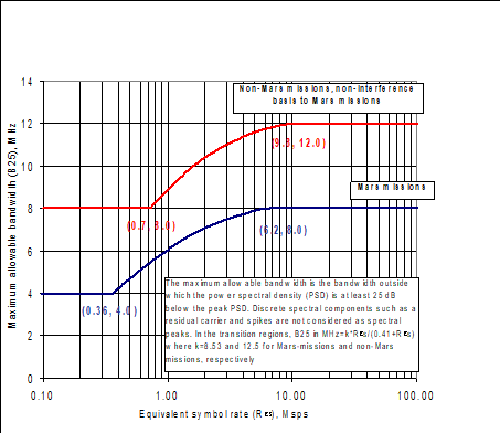 Figure 41: Maximum allowable bandwidth in the band 8 400 MHz - 8 450 MHz
Frequency assignment procedure
Choice of frequencies
The assignment of individual frequencies in the selected band or bands shall conform to the frequency management procedure established by the frequency coordinator.
Prior to the design phase of any spacecraft project, the project shall request the frequency assignments for the spacecraft.
For the purpose of requirement 4.3.1.b the project shall supply to the frequency coordinator the information that conforms to his specifications.
The information that is supplied in 4.3.1.c shall be identified if it is in a preliminary state and is to be confirmed (and finalized) at a later date.
The entire procedure of selection of frequencies shall be carried out under the management of the frequency coordinator.
The frequency coordinator has the exclusive authority for assigning frequencies.
All requests for frequency assignments or inquiries regarding frequency management matters shall be addressed to the frequency coordinator.
Advance publication, coordination and notification of frequencies
The project manager shall provide, to the frequency coordinator, the data regarding the frequencies used by the spacecraft to enable the advance publication, coordination and notification procedures of ITU/RR/9 and ITU/RR/11 no later than three years before the planned launch date.
The format established by the frequency coordinator shall be used for the purpose of 4.3.2.a.
At this stage, the data supplied as per 4.3.1 shall be the final data.
The procedures of ITU/RR/9 and ITU/RR/11 shall be carried out by the frequency coordinator for the satellites and Earth stations, in conformance with frequency management procedures.
Transmitted signals
Turnaround frequency ratio for coherent transponders
Generation of the transmitted carrier
Transponders, flown on the spacecraft for the purpose of coherent Doppler tracking, can generate the transmitted carrier from the received carrier by means of phase-lock techniques.
Band pairs
Band pairs should be selected from Table 51 together with the applicable turn-around ratio.
If the turnaround ratios in Table 51 are not used, the ratios in Table 52 shall be used.
Table 51: Turnaround frequency ratios for coherent transponder operation
|
|
Earth-space (MHz)
|
Space-Earth (MHz)
|
Turnaround ratio (fup/fdown)
|
|
Cat. A
|
2 025,833 333 – 2 108,708 333
|
2 200 – 2 290
|
221/240
|
|
2 025 - 2110
|
25 500 – 27 000
|
221/2772
| |
|
7 192,102 273 – 7 234,659 091
|
8 450 – 8 500
|
749/880
| |
|
Cat. B
|
2 110,243 056 – 2 117,746 142 a
|
2 291,666 667 – 2 299,814 815
|
221/240
|
|
2 110,243 056 – 2 119,792 438 a
|
8 402,777 780 – 8 440,802 468
|
221/880
| |
|
7 147,286 265 – 7 177,338 735
|
2 290,185 185 – 2 299,814 815
|
749/240
| |
|
7 149,597 994 – 7 188,897 377
|
8 400,061 729 – 8 446,234 569
|
749/880
| |
|
7 147,286 265 – 7 188,897 377
|
31 909,913 580 – 32 095,691 358
|
749/3344
| |
|
34 354,343 368 – 34 554,287 799
|
8 400,061 729 – 8 448,950 615
|
3599/880
| |
|
a See clause 4.2.1.1.
| |||
Table 52 Alternative turnaround frequency ratios for coherent transponder operation
|
|
Earth–space (MHz)
|
Space–Earth (MHz)
|
Turnaround ratio(fup/fdown)
|
|
Cat. A
|
2 074,944 444 – 2 087,222 222
|
8 450 – 8 500
|
221/900
|
|
7 190 – 7 235
|
2 255,686 275 – 2 269,803 922
|
765/240
| |
|
Cat. B
|
2 110,243 056 – 2 119,792 438 a
|
31 930,555 556 – 32 075,049 383
|
221/3 344 b
|
|
34 343,235 339 – 34 487,639 661
|
2 290,185 185 – 2 299,814 815
|
3599/240 b
| |
|
a See clause 4.2.1.1.
| |||
Carrier frequency stability
Spacecraft transmitter
The frequency stability of the transmitted RF carriers shall be within the limits specified in Table 53.
Table 53: Frequency stability for spacecraft transmitters
|
Frequency band (MHz)
|
Maximum frequency instability
|
|
2 200 – 2 2908 450 – 8 500
|
±2 × 10⁻⁵ under all conditions and for the lifetime of the spacecraft.
|
|
8 025 – 8 400
|
±2 × 10⁻⁵ under all conditions and for the lifetime of the spacecraft.
|
|
2 290 – 2 3008 400 – 8 450
|
±2 × 10⁻⁵ under all conditions and for the lifetime of the spacecraft.
|
|
31 800 – 32 300
|
±1,5 × 10⁻⁶ at any one temperature of transmitter in the range +10 C to +40 C in any 15 h following 4 h of warm-up.
|
In addition to clause 5.2.1.a for Category B missions the short term frequency stability shall be such that the resulting phase error when tracking the carrier with a second-order PLL with loop bandwidth 2BL as specified for the mission, does not exceed 10 degrees peak in high signal-to-noise conditions and in non-coherent mode.
- 1 The “short term frequency stability” includes phase noise contribution and any “instantaneous” phase or frequency variations (“discontinuities”) due to technological aspects and related to oscillator implementation.
- 2 Depending on the link budget and on the ground station 2BL value, this requirement may have strong impact on the onboard subsystem architecture and the selection of the proper oscillator technology.
Spacecraft receiver
The frequency stability of spacecraft receivers shall be within the limits specified in Table 54.
For phase lock loop receivers the frequency referred to is the best lock frequency.
Table 54: Frequency stability for spacecraft receivers
|
Frequency band (MHz)
|
Maximum frequency instability
|
|
2 025 – 2 1107 190 – 7 235
|
±2 × 10⁻⁵ under all conditions including ±4,8 × 10⁻⁶ initial setting error. Aging over seven years ±7,1 × 10⁻⁶.
|
|
2 110 – 2 1207 145 – 7 190
|
±2 × 10⁻⁵ under all conditions including ±4,8 × 10⁻⁶ initial setting error.
|
|
34 200-34 700
|
±1,7 × 10⁻⁵ at any one temperature in the range +10 C to +40 C in any 15 h after a warm-up period of 4 h.
|
Ground station equipment
The RF carriers transmitted by the Earth station shall be phase locked to a reference frequency standard having an accuracy of at least ±5 × 10⁻⁹ under all conditions.
Stability requirements on ranging and Doppler tracking can be found in ECSS-E-ST-50-02.
Polarization
Earth-space and space-Earth links shall be circularly polarized.
For a right-hand circularly-polarized wave, the sense of polarization determined by the electric field vector rotates with time in a right-hand or clockwise direction when observed in any fixed plane, normal to the direction of propagation, whilst looking in the direction of propagation.
Earth stations shall be capable of transmitting right-hand or left-hand circular polarization upon discretion of the user.
- 1 For practical reasons, spacecraft generally use the same sense of polarization for the Earth-space link and the space-Earth link.
- 2 Most Earth stations have the capability of combining two orthogonal circular polarizations on the space-Earth link.
Occupied bandwidth considerations
The occupied bandwidth shall not be wider than the maximum values given in Table 55, where ft is the ranging tone frequency and Rs the symbol rate, reciprocal of the symbol duration defined in Figure 61 and Figure 62.
- 1 There are no requirements for occupied bandwidths for the 25,5-27,0 GHz, 31,8-32,3 GHz, 34,2-34,7 GHz, 37,0-38,0 GHz and 40,0-40,5 GHz bands at the time of publication of this Standard. Users interested in the use of these bands can contact the frequency coordinator for advice.
- 2 The values given in Table 55 represent the maximum values, however it is specified in ITU/RR/3.9 that all efforts are made to restrict the occupied bandwidth.
Table 55: Occupied bandwidth
|
Frequency band (MHz)
|
Function
|
Category
|
Maximum occupied bandwidth
|
|
2 025 – 2 120and7 145 – 7 235
|
Telecommand (8 kHz subcarrier)
|
A & B
|
50 kHz
|
|
Telecommand (16 kHz subcarrier)
|
A & B
|
100 kHz
| |
|
Telecommand (direct modulation)
|
A & B
|
12 × Rs
| |
|
Ranging
|
A & B
|
2,5 × ft c
| |
|
2 200 – 2 290and 8 450 – 8 500
|
Telemetry a(Rs < 10 ksps)
|
A
|
300 kHz
|
|
Telemetry a (10 ksps Rs 60 ksps)
|
A
|
1 200 kHz or 30 × Rs, whichever is smaller
| |
|
Telemetry (60 ksps < Rs < 2 Msps)
|
A
|
1 200 kHz or 12 × Rs, whichever is larger, up to 6 MHz at 2 GHz and 10 MHz at 8 GHz
| |
|
Telemetry (Rs 2 Msps)
|
A
|
1,1 × Rs, up to 6 MHz at 2 GHz and 10 MHz at 8 GHz
| |
|
Ranging
|
A
|
2,5 × ft
| |
|
2 290 – 2 300
|
Telemetry (Rs 2 Msps)
|
B
|
1,2 × Rs b
|
|
8 025 – 8 400
|
Telemetry
|
-
|
1,1 × Rs
|
|
2 290 – 2 300and8 400 – 8 450
|
Ranging
|
B
|
2,5 × ft
|
|
8400 – 8 450
|
Telemetry (Rs < 2 Msps)
|
B
|
Shall meet requirements of Figure 41 for maximum allowable bandwidth
|
|
Telemetry (Rs 2 Msps)
|
B
|
1,2 × Rs, and shall meet requirements of Figure 41 for maximum allowable bandwidth
| |
|
a For missions with several data rates, the maximum occupied bandwidth for the highest data rate may also be applied to the lower rates.
| |||
Emissions
Unwanted emission power level
Transmitter spurious emissions and harmonics
The spurious emissions, including harmonics, generated by spacecraft and Earth station transmitters shall not exceed the levels given in Table 56.
This is consistent with ITU/RR/AP3.
Table 56: Maximum level of spurious emissions
|
Carrier frequency a (MHz)
|
Case
|
Maximum spurious level
|
|
100 – 40 500
|
Modulated and unmodulated transmissions b
|
-60 dBc, measured in a reference bandwidth of 4 kHz
|
|
Carrier harmonics of category B spacecraft transmitters
|
-30 dBc
| |
|
a The frequency range to be used for verification of this requirement is defined in recommendation ITU-R SM.329.
| ||
Protection of radio astronomy bands
Radio astronomy measurements performed as spectral line observations using narrow bandwidths and as continuum observations using wide bandwidths shall be protected from satellite unwanted emissions.
This is consistent with Recommendation ITU-R RA.769-2.
Unwanted emissions of a GSO satellite falling into the frequency bands of Radio Astronomy shall be kept to power flux density values 15 dB less than the limits given in Table 57 and Table 58, which apply to terrestrial sources of interference.
The 15 dB reduction of the Radio astronomy 0 dBi-gain protection levels from terrestrial sources is required by Recommendation ITU-R RA.769-2 for the GSO satellite emissions in the Radio astronomy frequency bands.
Unwanted emissions of a non-GSO satellite falling into the frequency bands of Radio Astronomy shall be kept to a power flux density values less than the limits given in Table 57 and Table 58 (which apply to terrestrial sources of interference) by the following values:
- For a single satellite: 13 dB.
- For a networks composed of more than one satellite: a value obtained from the frequency coordinator.
- 1 The power flux density limits shown in Table 57 and Table 58 apply directly to terrestrial sources of emissions, assuming they are received through a 0 dBi radio telescope antenna side lobe. For satellite emissions, the radio telescope antenna gain is taken into account in the evaluation of the limit.
- 2 For the non-GSO case, Recommendation ITU-R RA 1513-1 establishes that an individual satellite can exceed the radioastronomy protection levels for up to 2 % of the observation time and Recommendation ITU-R M.1583 provides a rather complex mechanism to calculate the corresponding equivalent pfd (epfd) limit. The simpler alternative method provided here is based on the fact that the 2 % observation time limit can be translated into an equivalent sky blockage of 2 % of the hemisphere visible from the radiotelescope. The 13-dB value is obtained by entering half of the solid angle corresponding to 2 % of the visible hemisphere (equivalent to an antenna offset of 5,74 for a single satellite) into the reference radioastronomy antenna pattern (32-25 log ).
Table 57: Threshold levels of interference detrimental to radio astronomy spectral line (i.e. narrow bandwidth) observations at the surface of the Earth due to terrestrial interference sources (Recommendation ITU-R RA.769-2)
|
Centre frequency(MHz)
|
Assumed observation bandwidth of spectral line (kHz)
|
Power flux density over the observation bandwidth (dBW/m2)
|
|
327
|
10
|
-204
|
Table 58: Threshold levels of interference detrimental to radio astronomy continuum (i.e. wide bandwidth) observations at the surface of the Earth due to terrestrial interference sources (Recommendation ITU-R RA.769-2)
|
Centre frequency (MHz)
|
Assumed observation bandwidth (MHz)
|
Power flux density over the observation bandwidth(dBW/m2)
|
|
13,385
|
0,05
|
-201
|
Protection of Space Research (deep space) bands
Unwanted emissions falling into the frequency bands of Space Research (deep space) should be kept to power flux spectral density values less than those given in Table 59 at the deep space antenna sites.
From Recommendation ITU-R SA.1157-1 and SFCG Recommendation 14-1R1.
Whenever the limits of Table 59 are not met, coordination shall be initiated between the offending satellite and the Space Research (deep space) users, via the frequency coordinator.
This is consistent with SFCG Recommendation 14-1R1 and SFCG Administrative Resolution A12-1.
Table 59: Harmful interference levels at deep space antenna sites
|
Frequency band
|
Power flux spectral density at antenna location (dBW/m2/Hz)
|
|
2 290 MHz – 2 300 MHz
|
-257,0
|
|
8 400 MHz – 8 450 MHz
|
-255,1
|
|
31,8 GHz – 32,3 GHz
|
-249,3
|
|
37,0 GHz – 38,0 GHz
|
-251,0
|
Protection of launcher RF systems
Spurious emissions from spacecraft which are active during the launch shall be in conformance to the RF interface requirements of the launcher.
For guidance on the levels to be met by the spacecraft equipment in terms of directly measurable parameters (e.g. power, frequency in an antenna feed cable), the conversion method given in Annex C can be used. This annex also provides some examples of typical requirements for Ariane 5. Note that the conversion method given is used to derive an estimate of the values; however, the real requirement is on the actual field strength at the vehicle equipment bay antennas.
Cessation of emissions
Each spacecraft shall be fitted with devices to ensure the immediate cessation of its radio emissions by telecommand whenever such a cessation is requested.
This is consistent with ITU/RR/22.1.
Since the temporary cessation of emissions is an efficient means of RFI mitigation in densely occupied bands, the reliability of the devices used for the switch-off of emissions shall be commensurate with the mission lifetime.
See SFCG Recommendation 12-4R3.
Power flux density limits at the Earth's surface
The power flux density (PFD) at the Earth’s surface produced by emissions from a spacecraft, for all conditions and all methods of modulation, shall not exceed the values given in Table 510.
- 1 See ITU/RR/21.16.
- 2 � In all cases, the limits relate to the PFD, which are obtained under assumed free-space propagation conditions.
The PFD limits shall be applied during all mission phases.
This can involve means for reducing EIRP onboard the spacecraft.
Table 510: Power flux density limits at the Earth’s surface
|
Frequency (MHz)
|
Angle of incidence () above horizontal plane (degrees)
|
Power flux density (dBW/m2/4 kHz)
|
|
1 525 – 2 300
|
0 – 5
|
-154
|
|
5 – 25
|
-154 + 0,5 × (-5)
| |
|
25 – 90
|
-144
| |
|
8 025 – 8 500
|
0 – 5
|
-150
|
|
5 – 25
|
-150 + 0,5 × (-5)
| |
|
25 – 90
|
-140
| |
|
Frequency (MHz)
|
Angle of incidence () above horizontal plane (degrees)
|
Power flux density (dBW/m2/1 MHz)
|
|
25 500 – 27 000
|
0 – 5
|
-115
|
|
31 800 – 32 300
|
0 – 5
|
-120
|
|
37 000 – 38 000
|
0 – 5
|
-120
|
|
37 000 – 38 000
|
0 – 5
|
-125
|
Power flux density limits at the GSO in the 25,5 GHz - 27,0 GHz band
Satellites in Sun-synchronous orbit or in an orbit that is proximate to the orbits of the DRS user satellites shall not produce a power-flux-density greater than 155 dB(W/m2) in 1 MHz at any location on the geostationary orbit (GSO) for more than 0,1 % of the time.
Satellites in orbits other than that specified in 5.5.4a shall not produce a power-flux-density greater than –155 dB(W/m2) in 1 MHz at any location on the GSO for more than 1 % of the time.
Power limits for Earth station emissions
Frequency bands between 1 GHz and 15 GHz
Except for the Space Research service (deep space), the equivalent isotropically radiated power (EIRP transmitted in any direction towards the horizon by an Earth station operating in the frequency bands between 1 GHz and 15 GHz shall not exceed the following (where is the angle of elevation of the horizon viewed from the centre of radiation of the antenna of the Earth station and measured in degrees as positive above the horizontal plane and as negative below it):
- +40 dBW in any 4 kHz band for 0;
- (+40 + 3 × ) dBW in any 4 kHz band for 0 5. For the Space Research service (deep space), the EIRP towards the horizon for an Earth station shall not exceed +55 dBW in any 4 kHz band, regardless of the horizon elevation.
For angles of elevation of the horizon greater than 5, there is no restriction on the EIRP transmitted by an Earth station towards the horizon.
Frequency bands above 15 GHz
Except for the Space Research service (deep space), the EIRP transmitted in any direction towards the horizon by an Earth station operating in the frequency bands above 15 GHz shall not exceed the following (where is the angle of elevation of the horizon viewed from the centre of radiation of the antenna of the Earth station and measured in degrees as positive above the horizontal plane and as negative below it):
- +64 dBW in any 1 MHz band for 0;
- (+64 + 3 × ) dBW in any 1 MHz band for 0 5. For the Space Research service (deep space), the EIRP towards the horizon for an Earth station shall not exceed +79 dBW in any 1 MHz band, regardless of the horizon elevation.
For angles of elevation of the horizon greater than 5, there is no restriction for the EIRP transmitted by an Earth station towards the horizon.
Limits to elevation angles
No transmission shall be affected by Earth station antennas at elevation angles of less than the following (where the elevation angles are measured from the horizontal plane to the direction of maximum radiation, i.e. antenna main beam direction):
- 3 for the Space Operation and the Earth Exploration-Satellite services.
- 5 for the Space Research service, Category A.
- 10 for the Space Research service, Category B. Since host administrations for Earth stations may specify tighter minimum elevation limits, the minimum elevation angle for transmission shall be agreed with the frequency coordinator.
Time limitations on transmissions
Transmissions from Earth stations to spacecraft shall be limited in time to the periods during which actual Earth-space link telecommunications or tracking operations are carried out.
- 1 See also 4.2.
- 2 Example of Earth-space link telecommunications is telecommand.
Spacecraft telecommunication system designs shall not rely only on the presence of a continuous Earth-space carrier in the absence of telecommand or tracking operations.
Spacecraft shall limit their transmission of RF power towards the Earth to the periods when telecommunications or tracking operations are carried out. - 1 See also 4.2.
- 2 Example of space-Earth link telecommunication is reception of telemetry and data.
Modulation
Phase modulation with residual carriers
Application
Phase modulation shall be used for the following:
- Telemetry in the UHF (2 200 MHz – 2 300 MHz), SHF (8 400 MHz – 8 500 MHz) and EHF (31,8 GHz – 32,3 GHz) bands, unless modulation in accordance with clause 6.2 of this Standard is adopted.
- Telecommand in the UHF (2 025 MHz – 2 120 MHz), SHF (7 145 MHz – 7 235 MHz) and EHF (34,2 GHz – 34,7 GHz) bands.
- Ranging (Earth–space) in the UHF (2 025 MHz – 2 120 MHz), SHF (7 145 MHz – 7 235 MHz) and EHF (34,2 GHz – 34,7 GHz) bands.
- Ranging (space–Earth) in the UHF (2 200 MHz – 2 300 MHz), SHF (8 400 – 8 500 MHz) and EHF (31,8 GHz – 32,3 GHz) bands.
Modulating waveforms
The following modulating waveforms may be used:
- Telemetry, a subcarrier modulated by PCM data.
- Telemetry, PCM data, SP–L encoded.
- Telecommand, a subcarrier modulated by PCM data.
- Telecommand, PCM data, SP–L encoded.
- Ranging, the appropriate ranging baseband signal.
- 1 In the case of simultaneous telecommand, ranging and telemetry, when selecting telecommand and telemetry modulation schemes it is important to take into account their mutual interference.
- 2 See also ECSS-E-ST-50-02.
PCM waveforms and data rates
PCM data signals shall be limited to the waveforms and symbol rates given in Table 61 as follows.
- For the RF carrier bands of 2 025 MHz – 2 120 MHz, 7 145 MHz – 7 235 MHz, and 34 200 MHz – 34 700 MHz (telecommand):
- Use of NRZ–M for category B is prevented.
- Use of 4 ksps only with 16 kHz subcarrier.
Requirement 6.1.3a.1(a) is a restriction of CCSDS recommendation 401 (2.2.3) but is justified by the better performance of NRZ-L for Category B missions.
- For the RF carrier bands of 2 200 MHz - 2 300 MHz, 8 400 MHz - 8 500 MHz and 31 800 MHz - 32 300 MHz (telemetry), SP-L is prevented for symbol rates below 10 ksps.
For the definition of the PCM waveforms and symbol duration, refer to Figure 61 and Figure 62.
Table 61: PCM waveforms and rates for residual carrier modulation
|
RF carrier (MHz)
|
Function
|
Symbol rate (sps)
|
PCM waveform
|
Special limitations
|
|
2 025 – 2 1207 145 – 7 23534 200 – 34 700
|
Telecommand
|
4 000/2nn = 0,1..9
|
NRZ–LNRZ–M
|
1) See 6.1.3a.1(a)2) See 6.1.3a.1(b)
|
|
4 000 × 2nn = 1 .. 6 c
|
SP–L
|
|
||
|
2 200 – 2 3008 400 – 8 50031 800 – 32� 300
|
Telemetry a b
|
102 - 106
|
NRZ–LSP–L
|
1) See 6.1.3a.2
|
|
a Symbol rates below 100 sps can be supported on a case by case basis. Users interested in such support, can contact the network operation manager in charge of the ground network of interest.
| ||||
For all data signals producing a square wave baseband PCM waveform, the symbol asymmetry measured at 50 % of the peak-to-peak amplitude point shall not exceed 1 % with the symbol asymmetry defined as follows:Symbol Asymmetry = , where long and short symbol refers to the duration of the long and short symbols
SP–L shall not be used except for direct modulation of the RF carrier and therefore without subcarrier.
NRZ waveforms shall only be used when modulated onto a subcarrier.
 NRZ–L level A signifies symbol “1” level B signifies symbol “0”
SP–L level A during the first half-symbol followed by level B during the second half-symbol signifies symbol “1” level B during the first half-symbol followed by level A during the second half-symbol signifies symbol “0”
NRZ–M level change from A to B or B to A signifies symbol “1” no change in level signifies symbol “0”
Figure 61: PCM waveforms and symbol duration definition
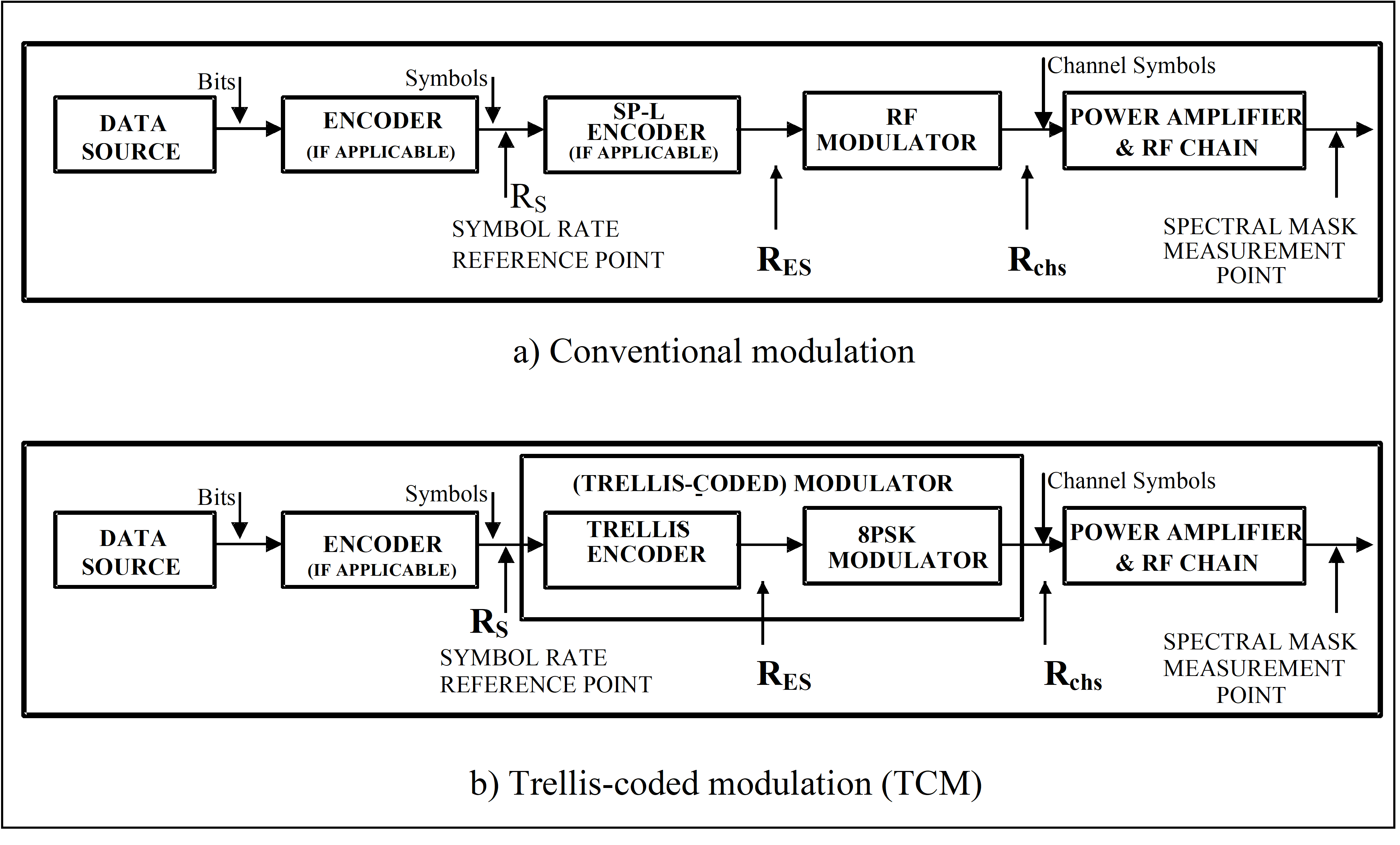 Figure 62: Symbol rate reference point
Use of subcarriers
Subcarriers
General
The subcarriers and modulating waveforms listed in Table 62 shall be used.
Table 62: Subcarriers used with phase-modulated carriers
|
RF Carrier (MHz)
|
Function
|
Subcarrier (kHz)
|
Modulation waveform
|
Subcarrier waveform
|
References
|
|
2 025 – 2 110 7 190 – 7 235
|
Telecommand (Category A)
|
8 or 16
|
NRZ–LNRZ–M
|
sine
|
See 6.1.4.1.2
|
|
2 110 – 2 1207 145 – 7 190 34 200 – 34 700
|
Telecommand(Category B)
|
8 or 16
|
NRZ–La
|
sine
|
See 6.1.4.1.2
|
|
2 200 – 2 2908 450 – 8 500
|
Telemetry(Category A)
|
2 – 300
|
NRZ–L
|
sine
|
See 6.1.4.1.3
|
|
2 290 – 2 3008 400 – 8 45031 800 – 32 300
|
Telemetry(Category B)
|
2 – 300
|
NRZ–L
|
square
|
See 6.1.4.1.3
|
|
a This choice is a restriction of CCSDS recommendation 401 (2.2.3) but is justified by the better performance of NRZ-L for Category B missions.
| |||||
Telecommand
For telecommand transmission using a subcarrier, only two subcarrier frequencies shall be used.
In the case specified in 6.1.4.1.2a when the 4 ksps symbol rate is used, the subcarrier shall be 16 kHz.
For telecommand symbol rates in excess of 4 ksps, the symbols shall be SP–L encoded and directly modulated onto the carrier.
Telemetry
For NRZ telemetry symbol rates above 60 ksps, subcarriers shall not be used and one of the following modulation schemes shall be used:
SP–L encoded symbols and direct modulation on the carrier for symbol rates as high as 1 Msps in the 2 200 MHz – 2 300 MHz and 8 400 MHz – 8 500 MHz bands.
Modulation in conformance to clause 6.2 of this Standard.
For telemetry subcarrier frequencies above 60 kHz, a subcarrier frequency-to-highest symbol rate ratio not exceeding 4 (for category A missions) or 5 (for category B missions) should be used, with a maximum subcarrier frequency of 300 kHz.
In case a ratio of 4 or 5 leads to spectral overlap with other signal components, the subcarrier frequency-to-highest symbol rate ratio shall be the smallest integer achieving less than 0,3 dB degradation (category A) or less than 0,1 dB degradation (category B) in the symbol detection process due to the other signal interference.
For missions with multiple symbol rates, the subcarrier frequency used for the highest symbol rate may be also used for the lower symbol rates.
Telemetry subcarrier frequencies shall conform to the following requirements:
- carrier acquisition by the ground receivers, as specified in clause 7.1;
- occupied bandwidth, as specified in clause 5.4;
- compatibility between ranging and telemetry.
For compatibility between ranging and telemetry, see ECSS-E-ST-50-02.
Subcarrier frequency stability
Telecommand subcarriers
The telecommand subcarrier shall have a frequency within ±1 × 10⁻⁵ of its nominal value.
The frequency stability shall be, as a minimum:
- ±5 × 10⁻⁶ over 24 h;
- ±1 × 10⁻⁶/s. For SP-L modulation, the stability requirements of 6.1.4.2.1a and 6.1.4.2.1b shall apply to the symbol rate.
Telemetry subcarriers
The telemetry subcarrier shall have a frequency within ±1 × 10⁻⁴ of its nominal value at all times.
The frequency variation due to power-supply voltage, temperature and other spacecraft influences shall be less than ±1 × 10⁻⁵ over any 5 minutes period.
The short-term frequency stability shall be a minimum of ±1 × 10⁻⁶, over any time period less than or equal to 100 times the subcarrier’s waveform period.
For SP-L modulation, the stability requirements of 6.1.4.2.2a, 6.1.4.2.2b and 6.1.4.2.2c shall apply to the symbol rate.
Subcarrier modulation
Modulation of subcarriers used for telemetry and telecommand shall be PSK.
The subcarrier frequency shall be an integer multiple of the symbol rate.
At each transition in the PCM waveform, the subcarrier shall be reversed in phase.
The transitions in the PCM waveform shall coincide with a subcarrier zero crossing to within ±2,5 % of a subcarrier period.
At all times, for more than 25 % of a subcarrier period after a phase reversal, the phase of the modulated subcarrier shall be within ±5 of that of a perfect PSK signal.
For NRZ waveforms, the beginning of the symbol intervals shall coincide with the following:
- For NRZ–M waveforms: with a subcarrier zero crossing;
- For NRZ–L waveforms: with a positive-going subcarrier zero crossing for symbols “1” and with a negative-going zero crossing for symbols “0”.
Data transition density
To ensure recovery of the symbol clock by the ground demodulators, the transition density in the transmitted PCM waveform shall not be less than the following values:
- 125 in any sequence of 1 000 consecutive symbols for category A;
- 275 in any sequence of 1 000 consecutive symbols for category B.
To ensure recovery of the symbol clock by the ground demodulators, the maximum string of either ones or zeros shall be limited to 64 symbols.
When the specifications in 6.1.5a and 6.1.5b are not ensured for the channel by other methods, a pseudo-randomizer in conformance with ECSS-E-ST-50-01 clause 9 shall be used.
Carrier modulation index
The peak modulation index shall be between the minima and the maxima stated in Table 63.
When two or more channels are transmitted simultaneously on the Earth-space link, the combined peak modulation index (resulting from the linear sum of the peak indexes) should not exceed 1,75 rad.
When the specifications in 6.1.6b are not met, the combined peak modulation index shall be such that the resulting carrier suppression conforms to 6.1.11a.
Worst case tolerances shall be used to meet clause 6.1.6.
Table 63: Limits of the peak modulation index
|
Function
|
Min. (radians peak)
|
Max. (radians peak)
|
|
Telecommand (NRZ-L, NRZ-M)
|
0,2
|
1,4
|
|
Telecommand (SP-L)
|
0,2
|
1,0
|
|
Telemetry (sinewave subcarrier)
|
|
1,5
|
|
Telemetry (squarewave subcarrier or SP-L)
|
|
1,25 a
|
|
Ranging Earth-space
|
0,1
|
1,4
|
|
Ranging space-Earth
|
0,01 b
|
0,7
|
|
a A maximum of 1,39 rad can be used provided that the carrier tracking loop’s signal-to-noise ratio remains above 15 dB.
| ||
Sense of modulation
A positive-going video signal shall result in an advance of the phase of the radio frequency carrier.
For directly modulated SP-L waveforms a symbol “1” shall result in an advance of the phase of the radio frequency carrier at the beginning of the symbol interval, and a symbol “0” in a delay.
Modulation linearity
The phase deviation, as a function of the video voltage applied to the modulator, shall not deviate from the ideal linear response by more than ±3 % of the instantaneous value for deviations up to 1,5 rad peak.
Residual amplitude modulation
Residual amplitude modulation of the phase modulated RF signal shall be less than 2 %.
Carrier phase noise
The phase noise of the unmodulated carrier shall be measured in non-coherent mode.
Phase noise of the unmodulated carrier, integrated between 10 Hz and 100 kHz, shall be less than the following values:
- 2 r.m.s. at UHF (2 025 MHz – 2 110 MHz and 2 200 MHz – 2 290 MHz).
- 4 r.m.s. at SHF (7 190 MHz – 7 235 MHz, and 8 450 MHz – 8 500 MHz).
Phase noise of the unmodulated carrier, integrated between 0,1 Hz and 1 kHz, shall be less than 1 r.m.s. at UHF (2 110 MHz – 2 120 MHz and 2 290 MHz – 2 300 MHz).
Phase noise of the unmodulated carrier, integrated between 1 Hz and 10 kHz, shall be less than the following values: - 4 r.m.s. at SHF (7 145 MHz – 7 190 MHz, and 8 400 MHz – 8 450 MHz).
- 10 r.m.s. at EHF (31,8 GHz - 32,3 GHz and 34,2 GHz - 34,7 GHz). If specifications 6.1.10b, 6.1.10c and 6.1.10d are not met over the indicated integration ranges, integration shall be carried out taking into account the mission selected loop bandwidths and symbol rates.
Residual carrier, out-of-band emission and discrete spectral lines
The residual power in the modulated carrier shall be greater than -15 dBc for space-Earth and -10 dBc for Earth-space links.
Discrete lines in the unmodulated transmitted RF signal spectrum, caused by baseband or RF bandwidth limitations, non-linearity of the channel, digital implementation of the frequency synthesis, or any other effects shall be less than -45 dBc inside the occupied bandwidth.
Modulation shall not result in the introduction of lines with power greater than -30 dBc in the occupied bandwidth.
Modulation shall not result in the introduction of discrete spectral lines greater than -30 dBc in the following frequency ranges around the carrier:
- ±60 kHz for UHF (2 200 MHz – 2 300 MHz);
- ±220 kHz for SHF ( 8 400� MHz – 8 500 MHz);
- ±850 kHz for EHF (31,8 GHz – 32,3 GHz).
For the case of filtered SP-L modulation, the spectral lines at the even multiples of the symbol rate shall not be higher than -20 dBc.
The out-of-band emission due to the modulation shall comply with the spectral roll-off of clause 6.3.
Suppressed carrier modulation,
Application and modulation schemes
Modulation with suppressed carrier shall be used rather than residual carrier phase modulation for telemetry in the UHF (2 200 MHz – 2 300 MHz), and SHF (8 025 MHz – 8 400 MHz and 8 400 MHz – 8 500 MHz) bands in the following cases:
- Where application of clause 6.1 can lead to power flux densities at the carrier frequency in excess of the limits specified in clause 5.5.3.
- In any case for symbol rates as defined by Figure 62 in excess of 1 Msps. For symbol rates in excess of 2 Msps (for the bands below 8 500 MHz) or 20 Msps (only for the 31,8 GHz - 32,3 GHz band) as defined by Figure 62, only TCM 8PSK (for the 8 025 MHz - 8 400 MHz band), filtered-OQPSK (for the bands below 8 400 MHz and for the 8 450 MHz – 8 500 MHz band) or GMSK (for all bands) shall be used.
Users are encouraged to also use modulation with suppressed carrier in the range of symbol rates from 60 ksps to 1 Msps for the bands below 8 500 MHz.
Data signals shall be PCM.
The following modulation schemes shall be used:
- BPSK (binary phase shift keying);
- QPSK (quadrature phase shift keying);
- UQPSK (unbalanced quadrature phase shift keying);
- OQPSK (offset quadrature phase shift keying);
- Filtered OQPSK;
- GMSK (Gaussian minimum phase shift keying);
- TCM 8PSK (8-ary phase shift keying). In the case of new projects, modulations 1 to 4 shall only be used for symbol rates of less than 2 Msps (for the bands below 8 500 MHz) or 20 Msps (only for the 31,8 GHz - 32,3 GHz band).
Modulating waveforms
The basic modulating PCM waveforms shall be used as per Table 64.
If the ground stations network for the mission concerned has the capability for using the synchronization marker(s) to resolve the phase ambiguity, such techniques shall be used without performing differential encoding for BPSK, QPSK, OQPSK and UQPSK signals.
If the ground stations network for the mission concerned does not have the capability to use the synchronization marker(s) to resolve the phase ambiguity, differential encoding shall be performed for BPSK, QPSK, OQPSK and UQPSK signals.
In convolutionary encoded systems using conversion between NRZ–L and NRZ–M, the conversion from NRZ–L shall take place before the input to the convolutional encoder, and the conversion from NRZ–M to NRZ–L shall take place after the output from the Viterbi decoder in order to maximise performance.
From a spectrum efficiency point of view, OQPSK should be used instead of QPSK.
Table 64: PCM waveforms
|
|
Without differential encoding
|
With differential encoding
|
|
BPSK
|
NRZ-L
|
NRZ-M
|
|
QPSK
|
NRZ-L
|
Q-DNRZ (see 6.2.3.2)
|
|
UQPSK
|
NRZ-L
|
NRZ-M
|
|
OQPSK
|
NRZ-L
|
Q-DNRZ (see 6.2.3.4)
|
|
Filtered OQPSK
|
NRZ-L
|
Q-DNRZ (see 6.2.3.4)
|
|
GMSK
|
|
Pre-coding (see 6.2.3.5)
|
|
TCM 8PSK
|
|
(see 6.2.3.6)
|
Carrier modulation
BPSK
The carrier shall be reversed in phase at each data signal transition.
The phase angle between the two constellation points shall be (180 ±2).
QPSK
The modulation shall be phase reversal keying of two phase quadrature carriers of equal amplitude by data channels with equal symbol rates with the constellation bit mapping of Figure 63.
The phase angle between the two quadrature carriers shall be (90 ±5).
The amplitude imbalance between the two quadrature carriers shall be less than 0,5 dB.
Modulation shall be such that for each channel, the suppression of the signal from the other channel is more than 21 dB.
The symbol clocks shall be synchronized to within ±2 % of the symbol period or 1 ns, whichever is larger.
In cases when Q-DNRZ differential encoding is used to remove phase ambiguity and I/Q channel reversal at the receiver side, the following differential encoding equations shall be used:
![]()
![]() where,
where,
E1 and E2 represent the two data streams at the input of the differential encoder;
E1 refers to the I-channel and E2 to the Q-channel;
An and Bn represent the data streams at the output of the differential encoder at time n;
An-1 and Bn-1 represent the output data streams at time n-1 (one symbol time before);
An refers to the I-channel and Bn to the Q-channel;
The parameters with a “bar” above represent the Boolean inverse;
The two streams An and Bn are used as I and Q in Figure 63.
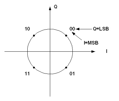 Figure 63: QPSK/OQPSK constellation mapping
UQPSK
The data shall consist of two channels with different symbol rates and the modulation shall be phase-reversal keying of two-phase quadrature RF carriers with different amplitude.
The phase angle between two quadrature carriers shall be (90 ±5).
The deviation from the theoretical amplitude imbalance between the two quadrature carriers shall be less than 0,5 dB.
Modulation shall be such that for each channel, the suppression of the signal from the other channel is more than 21 dB.
The symbol rate imbalance shall be more than 0,05.
The symbol rate imbalance is given by the equation:
![]() where Rs1 is the symbol rate of channel 1 and Rs2 the symbol rate of channel 2.
where Rs1 is the symbol rate of channel 1 and Rs2 the symbol rate of channel 2.
The power imbalance shall be in the range 4 dB to 10 dB.
Filtered and unfiltered OQPSK
The modulation shall be phase reversal keying of two phase quadrature carriers of equal amplitude by data channels with equal symbol rates with the Q-channel delayed by half a channel symbol period (being the channel symbol period ![]() ) with regard to the I-channel, and resulting in the constellation of Figure 63.
) with regard to the I-channel, and resulting in the constellation of Figure 63.
The phase angle between the two quadrature carriers shall be (90 ±5).
The amplitude imbalance between the two quadrature carriers shall be less than 0,5 dB.
Modulation shall be such that for each channel, the suppression of the signal from the other channel is more than 21 dB.
The symbol clocks shall be synchronized to within ±2 % of the symbol period or 1 ns, whichever is larger.
In case differential encoding is used, the convention for OQPSK shall be as follows:
![]() The stream of symbols ck, each one of duration
The stream of symbols ck, each one of duration ![]() is the input to the differential encoder. ck is split into two different steams a and b, each one of duration
is the input to the differential encoder. ck is split into two different steams a and b, each one of duration ![]() such that:
such that:
![]()
![]() The streams
The streams ![]() and
and ![]() are the outputs of the differential encoder and the inputs to the OQPSK modulator.
are the outputs of the differential encoder and the inputs to the OQPSK modulator.
- 1 In order to provide a better understanding on the implementation of the differential decoding, equations for the decoder are proposed below.
Decoder equations:
![]() where
where ![]() are the outputs of the demodulator and the inputs to the differential decoder.
are the outputs of the demodulator and the inputs to the differential decoder.
The stream of symbols at the output of the differential decoder ![]() is either given by:
is either given by:
![]() and
and ![]()
or
![]() and
and ![]()
depending on the ambiguity in the phase and sampling time delay in the receiver. In both cases the output data stream ![]() is the same.
is the same.
- 2 The sign ^ denotes an estimate of the variable. If there are no transmission errors, then
 (where
  is the original symbol stream input to the differential encoder).
If filtering is used, it shall be performed as follows: - For very high data rates in the 8 025 MHz – 8 400 MHz band when the hardware used does not support baseband shaping, post-amplifier shaping using a filter located at the output of the non-linear power amplifier as described in 6.2.3.4l.
- For all other cases, square-root raised-cosine (SRRC) baseband shaping filter with roll-off factor of 0,5 located prior to the modulator as described in 6.2.3.4i, 6.2.3.4j and 6.2.3.4k.
If filtering is used, the pre-detection filter (matched filter) in the receiver shall be an SRRC baseband shaping filter with roll-off factor of 0,5 as described in 6.2.3.4i, 6.2.3.4j and 6.2.3.4k.
The baseband SRRC filter shall have the normalized transfer function given by: where
where  is the Nyquist frequency.
The non-normalized value of H(f) can be obtained multiplying its normalized value by ![]() .
.
The impulse response of the SRRC filter shall be given by: 
In the case of digital implementation, the FIR filter impulse response shall be at least 16 bits long.
The post-amplifier filtering should be obtained with a 4 poles/2 zeros elliptic filter characterized with the normalized transfer function given in Figure 64.
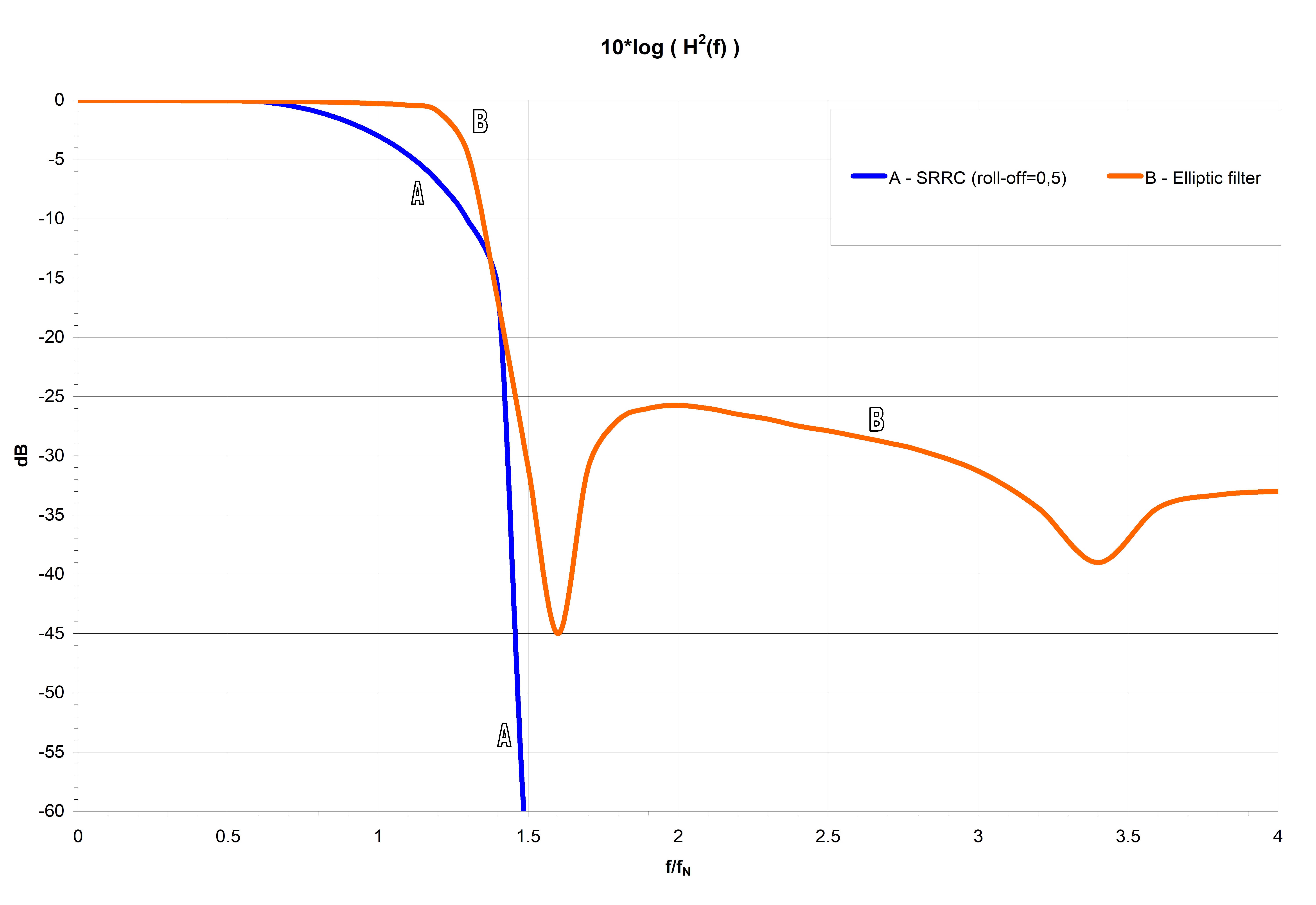 Figure 64: OQPSK post-amplifier filter transfer function
GMSK
The GMSK modulation format shall be as described in 9.1.
The NRZ-L source symbols are pre-coded prior to modulation.
For category A applications and for the 8 025 MHz – 8 400 MHz band, a BTS = 0,25 shall be used together with pre-coding where:
B = one-sided 3-dB bandwidth of the filter;
TS = symbol duration in accordance with Figure 61 and Figure 62.
For category B applications, a BTS = 0,5 shall be used together with precoding where:
B = one-sided 3-dB bandwidth of the filter;
TS = symbol duration in accordance with Figure 61 and Figure 62.
In the case of impairments the following conditions shall be met:
- For an I–Q implementation of the modulator:
- A phase angle between the two quadrature carriers of (90 ± 5).
- An amplitude imbalance between the two quadrature carriers of less than 0,5 dB.
- A modulation such that for each channel, the suppression of the signal from the other channel is more than 21 dB.
- For any implementation, a synchronization of the symbol clocks within ±2 % of the symbol period or 1 ns, whichever is larger.
- For digital implementation:
- A FIR filter impulse response of at least 4 bits long for category B applications and 5 bits long for category A applications.
- A minimum number of bits for the FIR coefficient quantization of 12.
4 dimensional 8PSK–TCM
The modulation format shall be as described in 9.2.
The NRZ-L input symbols are encoded differentially and convolutionally by the 4dimensional 8PSK-TCM modulator.
The phase angle between any two adjacent phase states shall be (45 ± 1,5) peak.
The amplitude imbalance between any two adjacent phase states shall be less than 0,3 dB peak.
The carrier rejection shall be at least 30 dB.
The side-band signal rejection shall be at least 30 dB, assuming, in the case of a linear modulator, a power variation of 6 dB in the modulating signal around the mean value.
Data transition density
To ensure recovery of the symbol clock by the ground demodulators, a pseudo-randomizer in conformance with ECSS-E-ST-50-01 clause 9 shall be used.
Symbol rate stability
The telemetry symbol rate shall be within ±1 × 10⁻⁴ of its nominal value at all times.
The telemetry symbol rate variation due to power-supply voltage, temperature and other spacecraft influences shall be less than ±1 × 10⁻⁵ over any 5 minutes period.
The telemetry symbol rate short-term variation shall be less than ±1 × 10⁻⁶, over any time period less than or equal to 100 times the symbol duration.
Carrier phase noise
The phase noise of the unmodulated carrier shall be measured in non-coherent mode.
Phase noise of the unmodulated carrier, integrated between 100 Hz and 1 MHz shall be less than 2 r.m.s. at UHF for the 2 200 MHz – 2 300 MHz band.
Phase noise of the unmodulated carrier, integrated between 100 Hz and 1 MHz shall be less than 6 r.m.s. at SHF for the 8 025 MHz – 8 500 MHz band.
Phase noise of the unmodulated carrier, integrated between 100 Hz and 1 MHz shall be less than 10 r.m.s. at EHF for the 25,5 GHz – 27,0 GHz and 31,8 GHz – 32,3 GHz. bands.
If specifications 6.2.6b, 6.2.6c and 6.2.6d are not met over the indicated integration ranges, integration shall be carried out taking into account the mission selected loop bandwidths and symbol rates.
Carrier suppression, out-of-band emission and discrete spectral lines
The carrier suppression shall always be greater than 30 dBc.
Discrete lines in the transmitted RF signal spectrum, caused by baseband or RF bandwidth limitations, non-linearity of the channel, or any other effects shall be less than -45 dBc inside the occupied bandwidth.
Modulation shall not result in the introduction of lines with power greater than -30 dBc in the occupied bandwidth.
The out-of-band emission due to the modulation shall conform to the spectral roll-off of clause 6.3.
Spectral roll-off
The emitted telemetry spectrum for all Space Science services projects, which utilize space-to-Earth link frequency assignments in the bands 2 200 MHz - 2 290 MHz, 8 025 MHz - 8 400 MHz, or 8 450 MHz - 8 500 MHz with symbol rates RS higher than 60 ksps shall adhere to the spectral emission masks of Figure 65 when measured at the reference point shown in Figure 62, where RES is as follows:
- For SP-L modulation, two times the NRZ symbol rate RS, reciprocal of the symbol duration defined in Figure 61 and Figure 62 (RES = 2 x RS).
- For 8PSK TCM modulation, includes the overhead due to the signal processing up to the constellation mapper output (see Figure 91 and 9.2.6.2b).
- In any other case, equal to RS, reciprocal of the symbol duration defined in Figure 61 and Figure 62.
- 1 See Figure 61 and Figure 62 for symbol rate definition.
- 2 The emitted spectrum is measured relative to the peak of the telemetry spectrum and excluding all spurious emissions.
- 3 None of the bands 2 200 MHz - 2 290 MHz, 8 025 MHz -8 400 MHz, or 8 450 MHz - 8 500 MHz, is allocated to space research deep space missions.
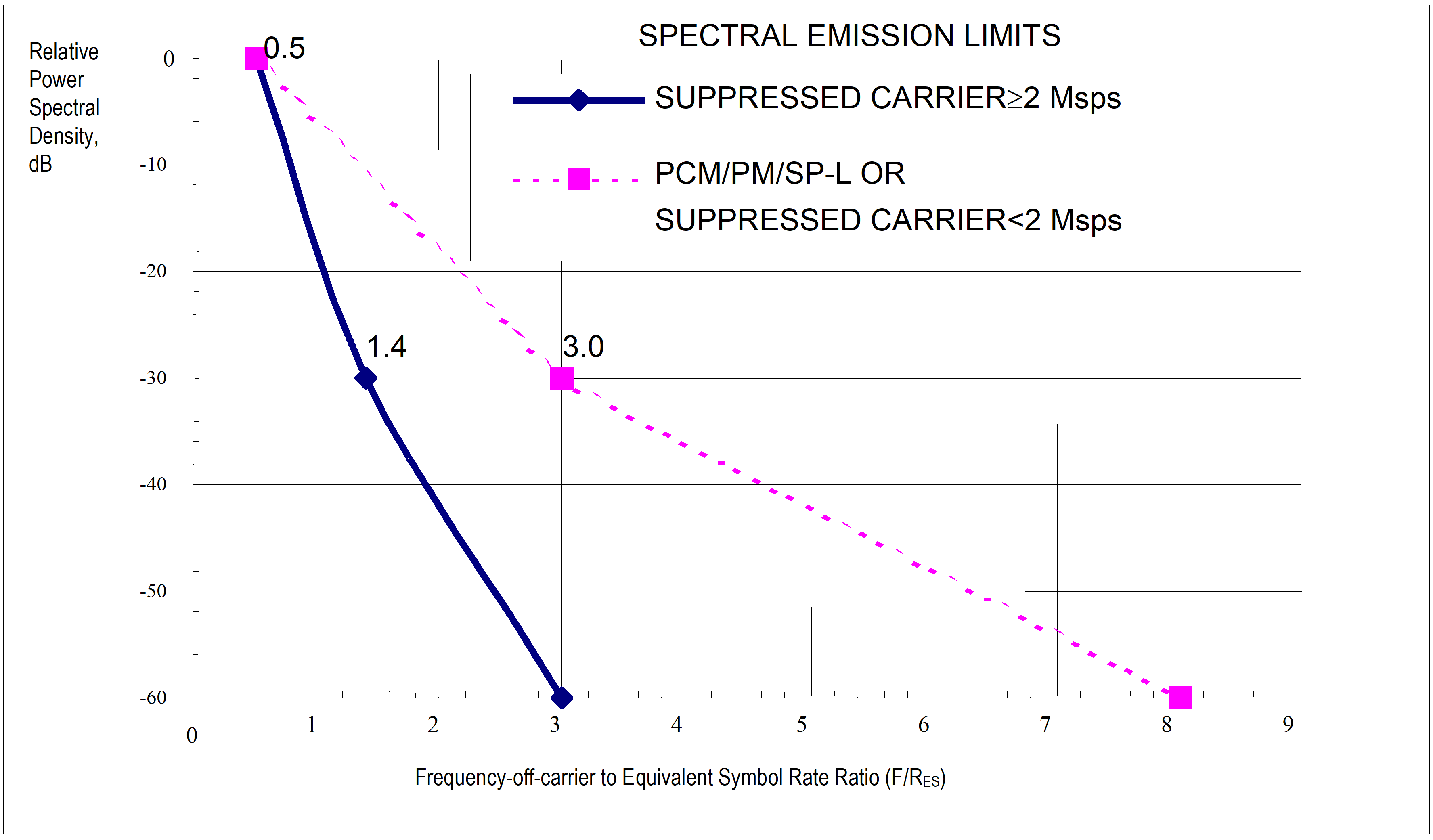 Figure 65: Spectral emission masks for telemetry transmission at symbol rates above 60 ksps
Link acquisition procedures
A-A-
Space-Earth
Normal operation
Overview
Under normal operation, the spacecraft transmitter is switched on by on-board automation at the time of scheduled commencement of the satellite “pass”, and the space-Earth link is modulated with the telemetry signal, containing at least the satellite housekeeping data.
Requirement
For safe acquisition, a period of time commensurate with a triangular frequency search in the worst case condition on link margin shall be allowed.
This is independent of the methods used for the acquisition of the Earth station receivers and demodulators.
Alternative mode of operation
As a secondary mode of operation, the spacecraft transmitter shall have capability to be activated by telecommand.
The telecommand referred in 7.1.2.a should be issued after the frequency sweep referred to in 7.2.
Coherent mode
If the coherent mode of the spacecraft transmitter is used, this shall be activated automatically or by telecommand, in the latter case, after acquisition of the Earth-space link is confirmed.
When the status of the transponder changes between coherent and non-coherent, and the resulting frequency step in the space-Earth link causes a loss of telemetry, a new acquisition of the space-Earth link shall be performed.
Earth-space
2 025 MHz - 2 110 MHz category A
During acquisition, no data or subcarrier modulation shall be present on the RF carrier transmitted by the ground station.
The carrier shall be swept in frequency with a symmetrical triangular waveform, i.e. the frequency shall be linearly swept around a centre frequency, with suitable amplitude and shall be phase continuous.
After a single sweep the frequency shall return to the centre value.
If Doppler compensation is used, then Doppler shift predictions with an error of 5 kHz maximum shall be available at the station.
The centre frequency can be offset from the assigned value to compensate for Doppler shift and, if this information is available, for drift of the transponder local oscillator.
The sweep amplitude shall be selected to:
- ensure sweeping over the transponder best lock frequency;
- remain inside the transponder tracking range. The lock status of the transponder shall be transmitted in the spacecraft telemetry data for operational use by the Earth station.
A standard location of the transponder lock status telemetry is specified in the Command Link Control (CLCW) as described in clause 6.3 of ECSS-E-ST-50-04.
After receipt of the confirmation of lock, the Earth station shall bring the carrier frequency to the assigned value.
All frequency excursions shall take place at a constant rate, selected such that the transponder phase-lock loop has no difficulty acquiring the carrier and tracking the sweep.
Any frequency discontinuities and jumps shall be smaller than 1/100 of the transponder PLL lock-in range.
The following values, consistent with a transponder second order phase-lock loop bandwidth 2 BL = 800 Hz and a damping factor 0,7 < < 1,2, should be used:
- Maximum sweep rate: 32 kHz/s.
- Maximum discontinuity: 10 Hz.
- Maximum sweep range: ±150 kHz. The Earth station design should be such that it can support transponders with other PLL loop bandwidths.
This can be achieved by including flexibility on the parameters given in 7.2.1j.
Onboard demodulators shall not use frequency sweep for subcarrier (when present) or bit clock acquisition.
Subcarrier (when present) and bit clock acquisition shall be achieved using the preamble transmitted before all uplink messages.
The idle sequence as specified in clause 9.2.3 of ECSS-E-ST-50-04 is transmitted at all times (except during acquisition) to limit the power spectral density from the Earth transmitters.
2 110 MHz - 2 120 MHz category B
The acquisition procedure shall be the same as that described in 7.2.1 for 2 025 MHz - 2 110 MHz, except that Doppler compensation of the uplink carrier frequency is performed and that the carrier frequency is not brought to the assigned value after acquisition.
The compensation for Doppler shift and transponder local oscillator drift shall be corrected with a periodicity that ensures that the received frequency remains within ±5 kHz of the estimated best lock frequency.
Further frequency corrections need not be performed (such as the continuous compensation of Doppler shift).
To provide a means of estimating the best lock frequency, the transponder PLL error voltage (loop stress) shall be transmitted to the ground via the spacecraft telemetry.
The resolution of this information shall correspond to frequency steps of the order of the PLL bandwidth (2 BL) or less.
The Earth station shall have capability to support a continuous frequency sweep with the following specifications:
- Sweep rate: 1 Hz/s to 10 kHz/s.
- Sweep range: ±100 Hz to ±300 kHz.
7 145 MHz - 7 190 MHz category B
The acquisition procedure shall be the same as that described in 7.2.2, except that the sweep parameters are:
- Sweep rate: 1 Hz/s to 10 kHz/s.
- Maximum sweep range: ±1 MHz.
7 190 MHz – 7 235 MHz category A
The acquisition procedure shall be the same as that described in 7.2.1, except that the sweep parameters are:
- Sweep rate: 100 Hz/s to 50 kHz/s.
- Maximum discontinuity: 1 Hz.
- Maximum sweep range: ±500 kHz. The Earth station design should be such that it can enable the support of transponders with other PLL bandwidths.
This can be achieved by including flexibility on the parameters given in 7.2.4a.
RF interface control
RF interface control documents
The following two documents cover the RF interface control between spacecraft and Earth stations:
Spacecraft-Earth station interface control document.
Link budget tables.
These documents are specified in detail in the subsequent clauses. The first document controls the RF interface. The second document is updated regularly to keep track of the development of the spacecraft and Earth station. Hardware interface compatibility is demonstrated by spacecraft-Earth station compatibility tests, which are documented in the following:
The compatibility test plan.
The compatibility test results.
Spacecraft-Earth station interface control document
Overview
The spacecraft-Earth station interface controls all the relevant parameters describing the interface between the spacecraft and the Earth stations.
Process
The first draft of the document shall be prepared in the Phase B (preliminary definition) of the project by the responsible engineering department using inputs from the study or project manager.
The document referred in 8.2.2.a. shall contain all the relevant parameters for any new ground systems to be developed for the project and for the computation of the link budget.
When the definitive spacecraft parameters are specified, the final version of the document should be produced and agreed upon by the project manager and the duly appointed representative of the network operations manager.
From the time the final version of the document is produced on, the document shall be under the control of the project manager, who shall agree with the responsible engineering department any changes to the parameters.
The spacecraft-Earth station interface control document shall be established in conformance with the DRD in Annex A.
The spacecraft-ground network interface control document shall act as a source document for all data to be used in the preparation of the link budget tables.
Link budget tables
General
Link budget tables shall be prepared by the spacecraft project responsible for the correct modelling of all aspects of the links between spacecraft and Earth stations.
The link budget tables shall be used throughout the course of the project to monitor the quality of the spacecraft-Earth network interface and be subject to verification by the engineering department responsible.
Although the exact format may vary from application to application, the same terminology and parameters shall be used.
For this purpose, the terminology and parameters of the telecommunication link design control table in CCSDS RF & Modulation Blue Book, CCSDS 401.0-B, Recommendation 4.1.2 are used with exception of the layout.
Parameters
Separate link budgets should be produced for all different parameter combinations (e.g. different Earth stations, different spacecraft antennas, and bit rates).
For a given set of parameters the link budget should be evaluated for the planned maximum distance of the spacecraft from the Earth for which these parameters are used.
For each parameter entering the link budget, three values should be used:
- The design value D, which is the value of the parameter expected under nominal conditions.
- The adverse tolerance A, which takes into consideration adverse conditions such as extreme temperatures, extreme voltages, end of life, and end of maintenance period.
The adverse tolerance is defined as the worst case of a parameter minus the design value in dB. Normally, the adverse tolerance is the value given in a design specification.
- The favourable tolerance F, which takes into consideration best case conditions such as benign environment beginning of life, and equipment recently maintained.
The favourable tolerance is defined as the best case of a parameter minus the design value in dB. Often the favourable tolerance, particularly in the design phase of a project, represents an informed estimate on how to improve the equipment over the original design.
From the design value, the adverse and the favourable tolerances, the mean value n and the variance (n2), based on a particular probability density function identified in Table 81 for each parameter should be calculated according to the equations given in Figure 81 for each of the distributions represented.
Table 81: Probability density functions for link budgets
|
Earth-space
|
Space-Earth
|
|
Uniform probability density functions
| |
|
E/S Antenna Gain (Tx)
|
S/C Antenna Circuit Loss (Tx)
|
|
Triangular probability density functions
| |
|
S/C Antenna Gain (Rx)
|
S/C Antenna Gain (Tx)
|
|
Gaussian probability density functions
| |
|
Atmospheric Attenuation
|
E/S Effective System Noise Temperature (Rx)
|
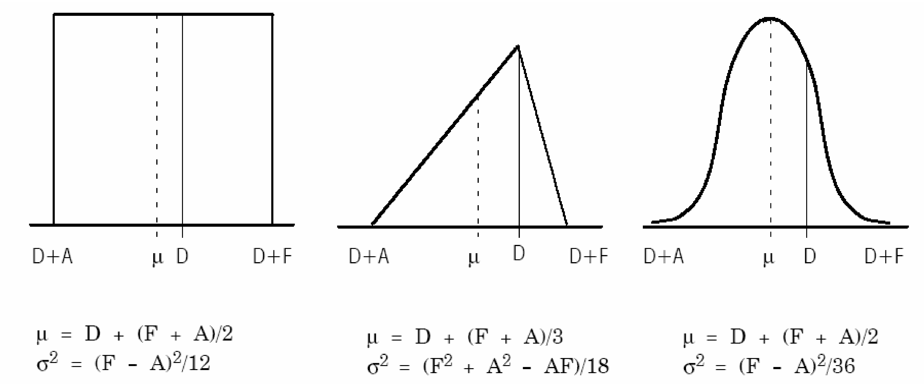 Figure 81: Parameter distributions and their equations
Margins for budgets based on the design value, favourable tolerance, adverse tolerance, mean value, mean -3 and worst case RSS should be calculated as follows:
- The margin for mean - 3 is:
margin for mean parameters
 .* The worst case RSS margin is:
margin for design parameters
.* The worst case RSS margin is:
margin for design parameters  .:::note
Note that the calculation of the variances of the margin from the sum of variances of its components, which have different density functions, is valid only if all the variances are of approximately the same magnitude.
:::
.:::note
Note that the calculation of the variances of the margin from the sum of variances of its components, which have different density functions, is valid only if all the variances are of approximately the same magnitude.
:::
If a particular variance is dominant, its statistics shall be treated separately.
The jitter performance of the recovered carrier shall be included in the calculation of the degradation in the demodulation processes.
Each project may have its own criteria for acceptability of link performance, using the various margins calculated in the link budget tables.
Margins based on design parameters should exceed 3 dB, and those on the RSS worst case and the mean -3 should exceed 0 dB.
These recommendations have been derived from practical experience.
The link budget tables should:
- be kept updated during the evolution of the project;
- reflect new information coming from the spacecraft unit, subsystem and system acceptance tests and from spacecraft-ground network compatibility tests.
Spacecraft-ground network compatibility test
The compatibility of the space element and the ground stations shall be tested in conformance with requirements on “Communication compatibility test” of clauses on “ Overall system qualification test” and “Overall system acceptance test” of ECSS-E-ST-10-03.
Specific ranging and Doppler tracking tests are given in clause 5 of ECSS-E-ST-50-02.
Such tests shall be made with representative models of spacecraft TTC flight equipment (engineering model as a minimum) and Earth station equipment.
See also clause B.1.1.4 of ECSS-E-ST-10-02.
Where new developments or extensive modifications of existing equipment are involved, preliminary tests should be made in an early phase of the programme using engineering, development or breadboard equipment.
The tests to be performed during compatibility testing vary from project to project. The purpose of the tests is always to establish thresholds and limiting values so that a good assessment of available margins can be made.
A compatibility test plan, detailing as a minimum the tests to be performed, the minimum required values for critical parameters, and the spacecraft and Earth station equipment to be used, shall be drawn up before commencement of the test activities.
At the conclusion of the tests, a compatibility test report, containing a formal statement on the compatibility of the spacecraft and the ground network, shall be issued by the engineering department responsible.
GMSK and 8PSK TCM modulation formats
GMSK modulation format
The modulated RF carrier shall conform to the following expressions:
![]() where
where
P is the power of the carrier;
f is the centre frequency;
(t) is the phase of the modulated carrier;
0 is a constant random phase;
and,
![]() where
where
ak = (-1)k dk dk-1 are the pre-coder output symbols;
dk = { ±1 } is the k-th information symbol to be transmitted.
The instantaneous frequency pulse g() is obtained through a linear filter with impulse response defined by:
![]() where
where
![]()
- means convolution,
h() is the Gaussian density function:
![]() where
where
![]() with
with
ln (n) = natural logarithm (base = e);
B = one-sided 3-dB bandwidth of the filter with impulse response h();
Ts = the duration of one input symbol as defined in Figure 61 and Figure 62.
The specified pre-coding suppresses the need for differential decoding at the receiver side and improves the receiver performances.
8PSK TCM modulation format
General principles
The MPSK-trellis coded modulation is based on the partitioning of one MPSK constellation into different subsets, each subset having a minimum Euclidian distance larger than the minimum distance of the original constellation.
With the use of a trellis coder prior to the modulator, the different phase states zk of the constellation are not independent and belong to the coded sequences of the trellis.
The use of a maximum likelihood decoder that is sensitive to the minimum Euclidian distance ![]() offered by these sequences, gives improved performances for the data recovery in the AWGN channel.
offered by these sequences, gives improved performances for the data recovery in the AWGN channel.
These performances are improved by the use of multidimensional trellis coded modulation, which also allows the automatic removal of carrier phase ambiguity at demodulator side.
4 dimensional 8PSK-TCM encoder
The 4 dimensional-8PSK trellis coded modulator shall combine a serial to parallel converter, a differential encoder, a trellis encoder, i.e. a convolutional coder, a constellation mapper and an 8PSK modulator
See Figure 91.
The trellis encoder shall be based on a 64 state systematic convolutional encoder.
The trellis encoder is considered as the inner code if a block code is introduced.
Carrier phase ambiguity shall be resolved by the use of a differential encoder located before the trellis encoder.
Spectral efficiency factor (SEF) of 2 symbols/channel symbol and 2,5 symbols/channel symbol shall be achieved by one of the architectures of the constellation mapper described in 9.2.5a and 9.2.5b.
If the input data stream is paralleled into b lines, for k multidimensional 8-ary channel symbols (k = 4 in this case) the spectral efficiency factor of the modulation is SEF = r = b/k. Figure 91 shows the general principle of the 4D-8PSK TCM modulator.
The constellation mapper shall deliver 4 parallel symbols coded with three bits to perform 8PSK modulation based on natural mapping (i.e., 0, 1, 2 …, 7 anticlockwise).
The output switch shall address successively each of the four possible channel symbols to the 8PSK modulator.
The four channel symbols shall be transmitted during “b” symbol times.
The constellation rate is therefore b/4. At SEF = 2, b= i = 8 while at SEF = 2,5, b = i = 10. Due to the trellis encoder the number of lines at the input of the constellation mapper is b + 1 (either 9 or 11).
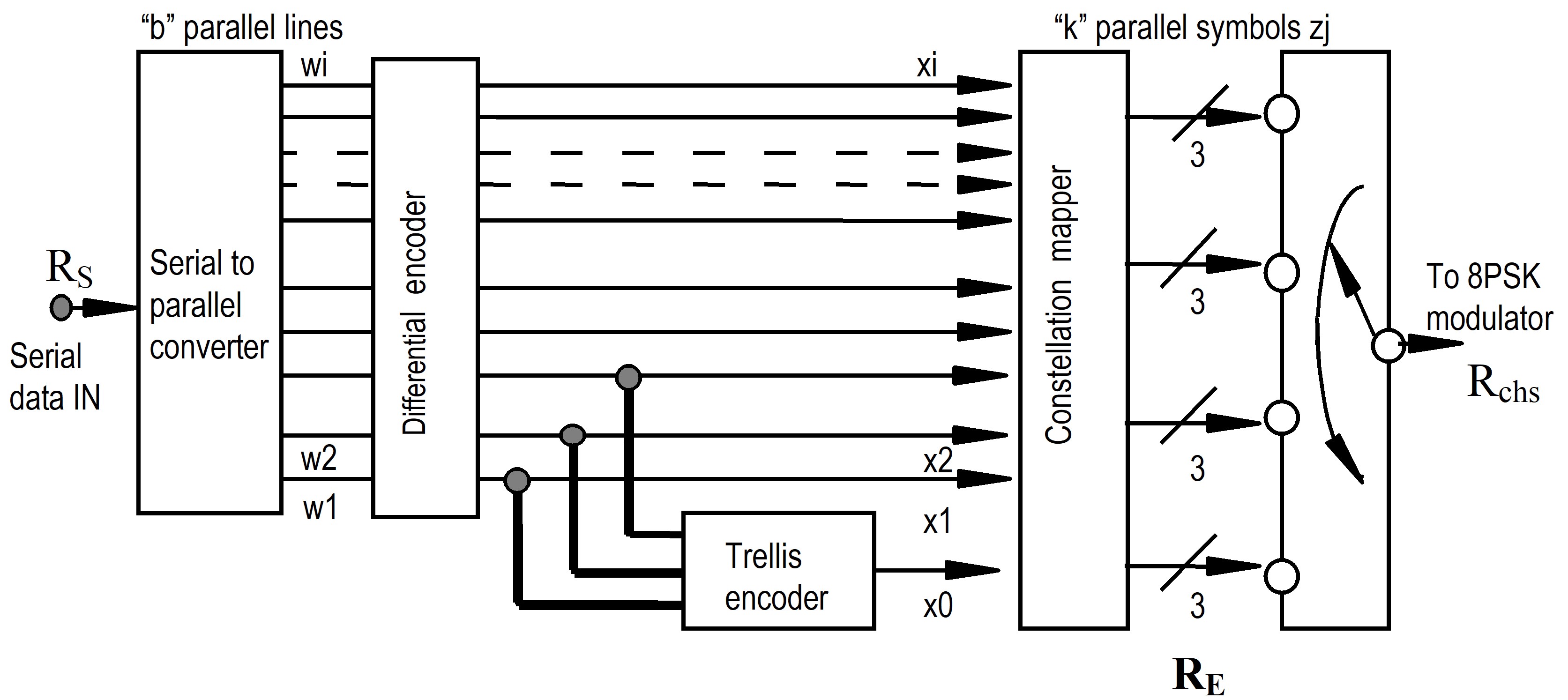 Figure 91: General principle of the 4D-8PSK TCM modulator
Differential encoders for SEF = 2 and 2,5
To eliminate 22,5 phase ambiguity on carrier synchronization, the codes represented in Figure 92 should be used.
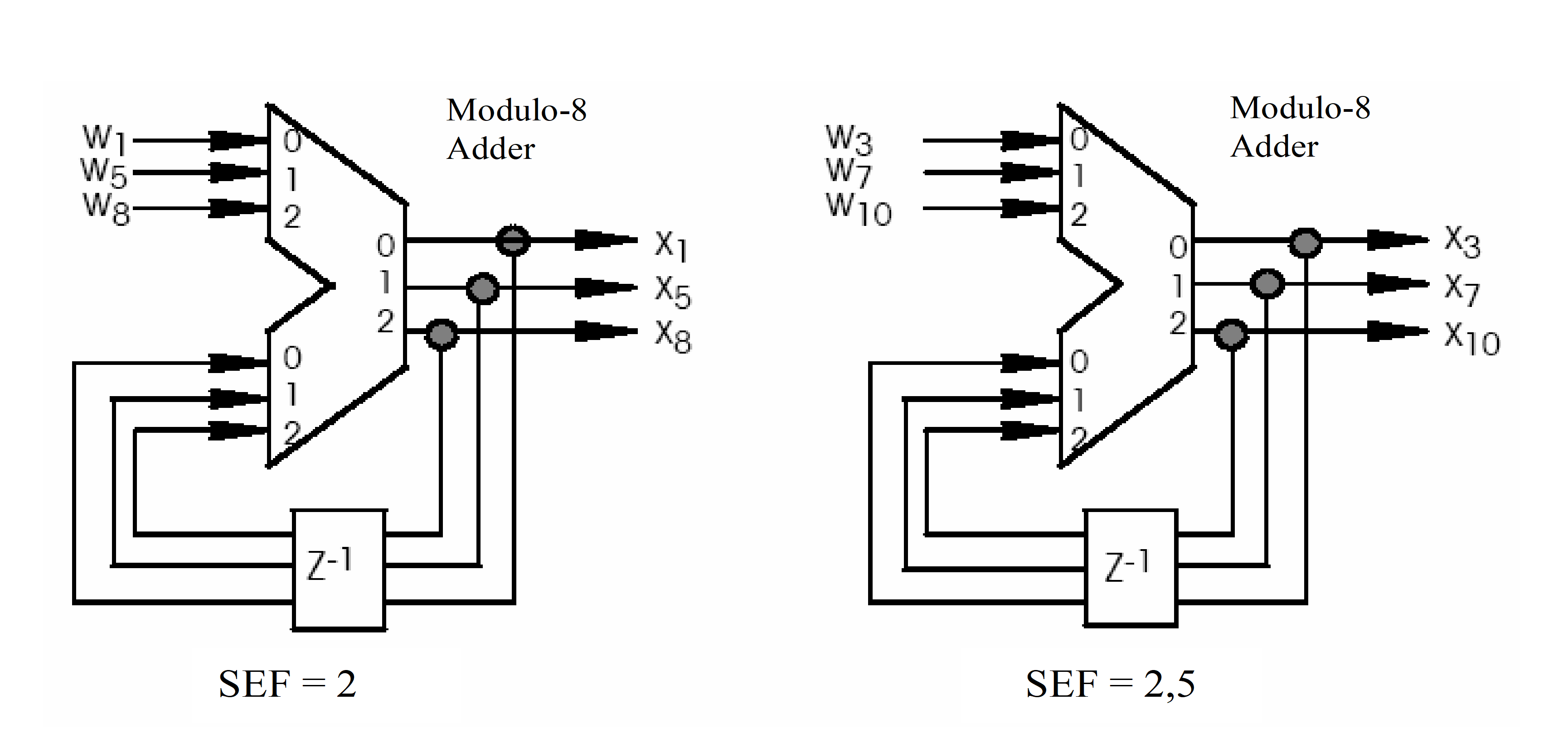 Figure 92: Codes to eliminate 22,5 phase ambiguity on carrier synchronization
Trellis encoder structure
The 64 states L = 7, rate 3/4 systematic trellis encoder shall be as represented in Figure 93, which is the same encoder for both SEF values.
The corresponding polynomials (in octal) are: h3 = 050, h2 = 024, h1 = 006, h0 = 103
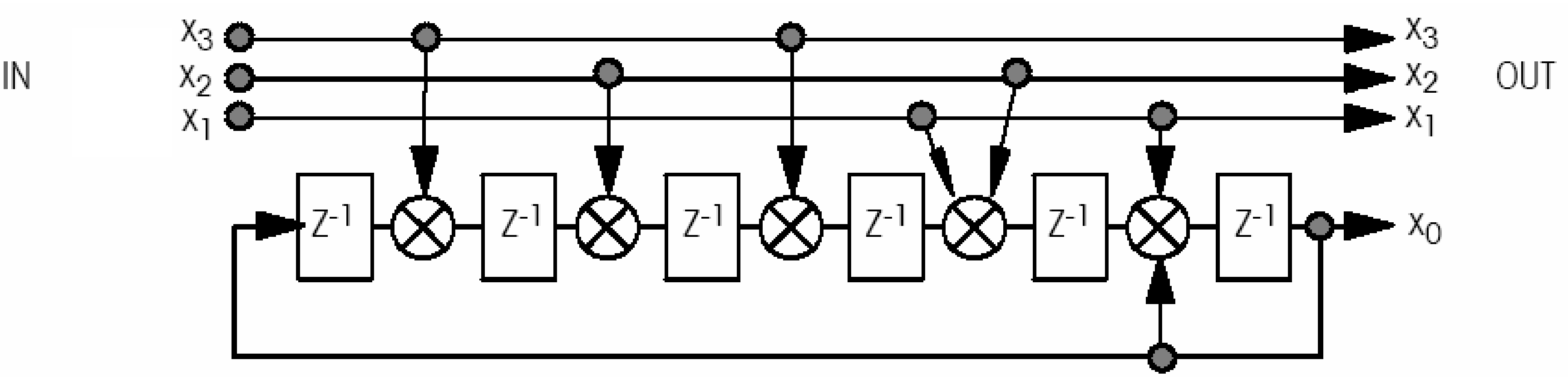 Figure 93: Representation of a 64 state L=7, rate 3/4 systematic trellis encoder
Constellation mapper for 4 dimensional 8PSK-TCM
The constellation mapper for SEF = 2 shall conform to Figure 94.
The constellation mapper for SEF = 2,5 shall conform to Figure 95.
The channel filtering shall be obtained according to the SRRC shaping located before the linear I/Q 8-PSK modulator.
A roll-off factor of 0,35 or 0,5 shall be used.
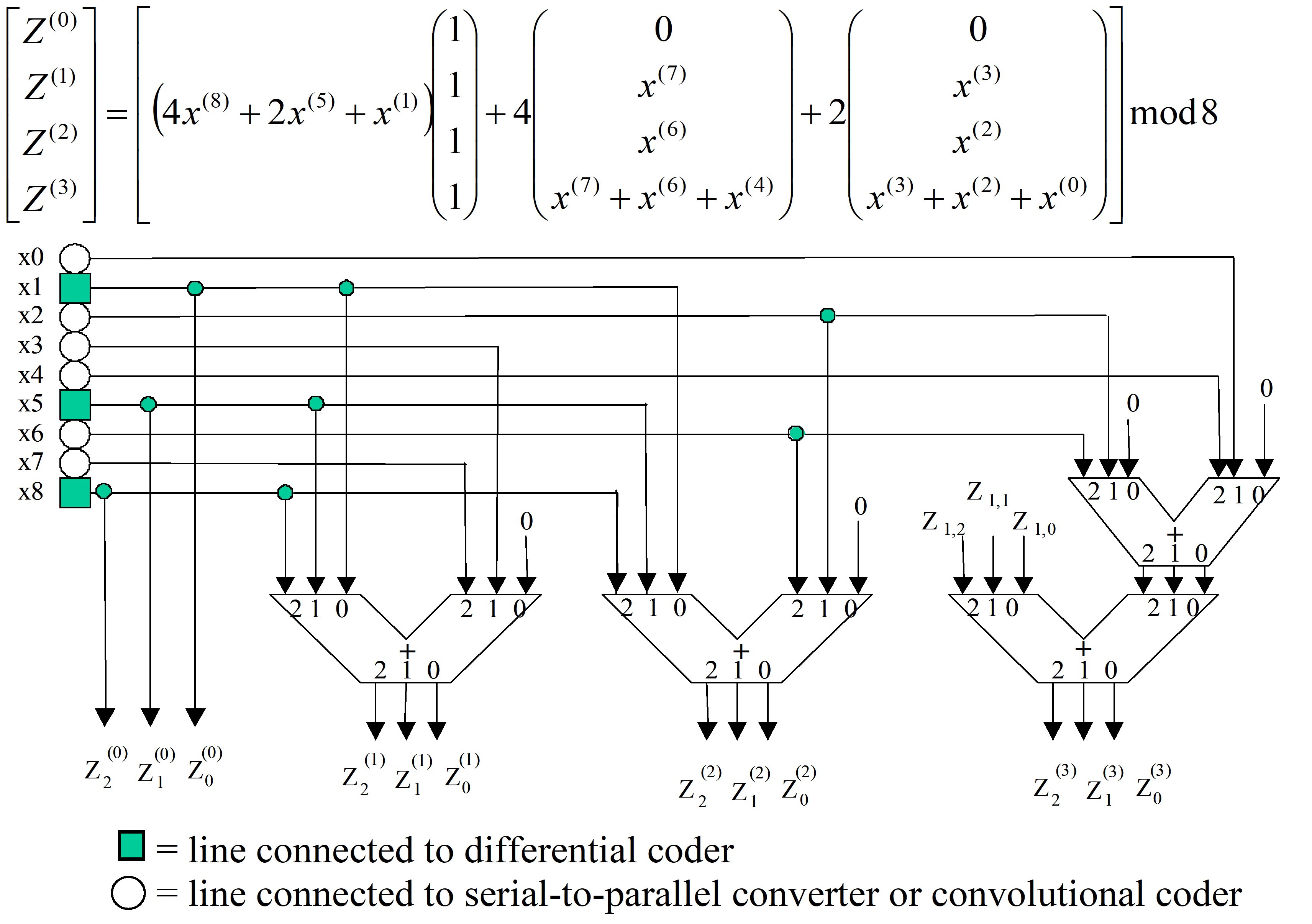 Figure 94: Constellation mapper for SEF = 2
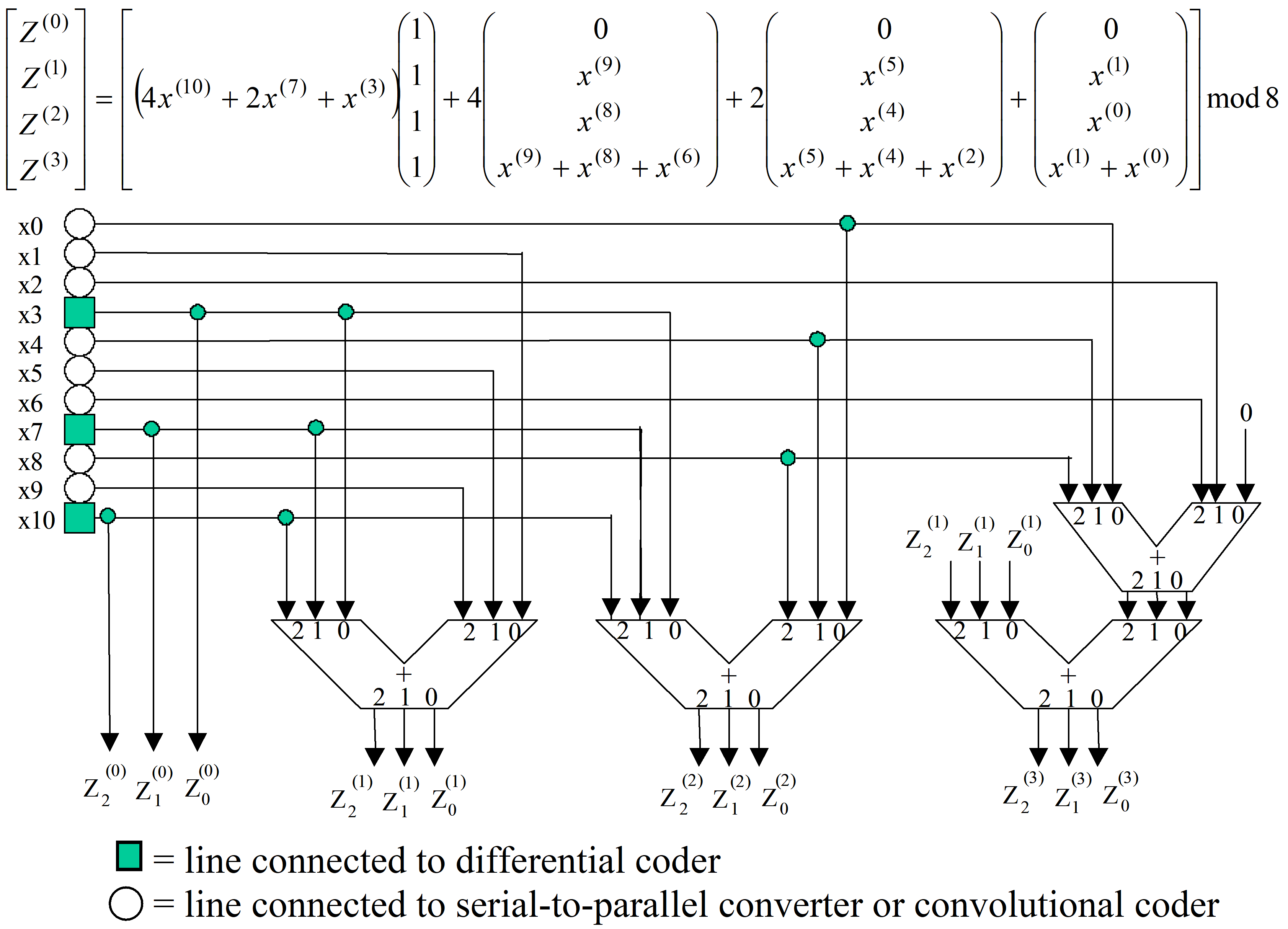 Figure 95: Constellation mapper for SEF = 2,5
Channel filtering
General
Channel filtering shall be obtained by one of the following two methods:
Square-root raised-cosine (SRRC) baseband shaping filter located prior to the modulator, with a channel roll-off factor of 0,35 (or 0,5) as described in 9.2.6.2.
This waveform shaping is used in association with a linear modulator and power amplifier.
Post-amplifier shaping using an output filter located at the output of the non-linear power amplifier as described in point 9.2.6.3.
In this case a NRZ-like shaping is used in conjunction with a non-linear 8-phase modulator.
In the two cases specified in 9.2.6.1 a, the pre-detection filter (matched filter) in the receiver shall be an SRRC filter with the roll-off factor of 0,35 or 0,5.
Baseband SRRC shaping
This type of channel filtering should be used for linear amplifier conditions, or with amplifier linearization, when the symbol rate to central frequency ratio is low.
The normalized transfer function of the SRRC filter shall be:
where ![]() = RES/6 is the Nyquist frequency and is the roll-off factor; andXX is equal to 4 for SEF = 2 and to 5 for SEF = 2,5.
= RES/6 is the Nyquist frequency and is the roll-off factor; andXX is equal to 4 for SEF = 2 and to 5 for SEF = 2,5.
The resulting overhead for computing RES from RS shall be 1,5 and 1,2 for SEF = 2 and for SEF = 2,5 respectively (RES =1,5 RS and RES =1,2 RS respectively).
The non-normalized value of H(f) can be obtained multiplying its normalized value by ![]() .
.
The corresponding transmit structure shall conform to Figure 96.
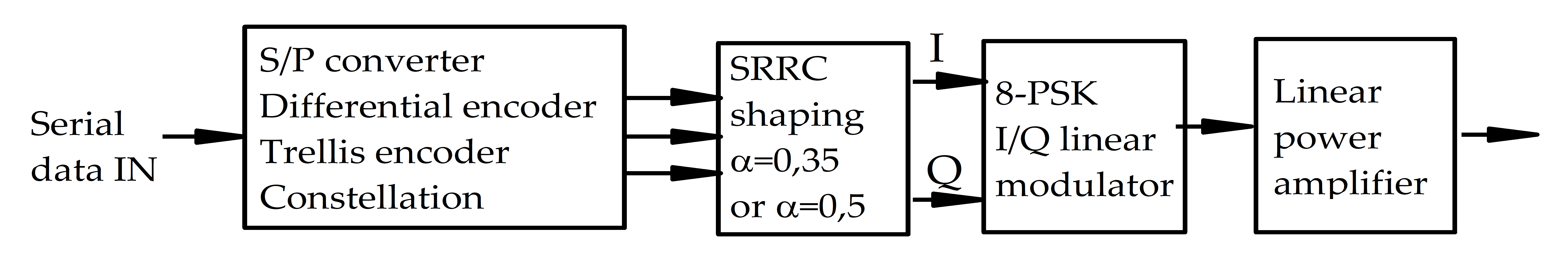 Figure 96: Transmit structure for baseband, square root raised-cosine shaping
Post-amplifier shaping
Post-amplifier shaping should be used for nonlinear amplifier conditions or when the symbol rate to central frequency ratio is high.
The output filtering should be obtained with a 4 poles/2 zeros elliptic filter characterized with the normalized transfer function given in Figure 97.
The corresponding transmit structure should conform to Figure 98.
Figure 97: Transfer function for a 4 poles/2 zeros elliptic filter
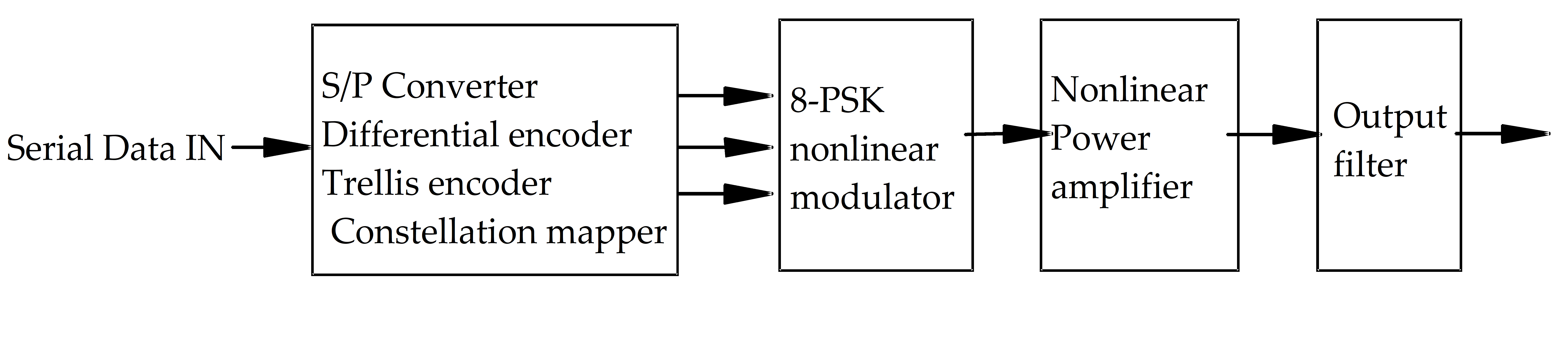 Figure 98: Transmit structure for post-amplifier shaping
ANNEX(normative)Spacecraft-Earth station interface control document - DRD
DRD identification
Requirement identification and source document
This DRD is called from ECSS-E-ST-50-05, requirement 8.2.2e.
Purpose and objective
The spacecraft-Earth station interface controls all the relevant parameters describing the interface between the spacecraft and the Earth stations.
Expected response
Contents
The Spacecraft-Earth station interface control document shall include the following information:
- Earth stations and time profile of use.
- Configuration of the equipment in the Earth stations and links to the control centre.
- Performances of Earth station (e.g. EIRP, G/T, and demodulation losses, with tolerances).
- Configuration of equipment on-board the spacecraft.
- Performances of spacecraft equipment (e.g. transmitter power, telecommand thresholds, and antenna gains, with tolerance).
- TTC standards applicable and any waivers granted.
- Choice of parameters for the links (i.e. which subsets of the parameters allowed by the standards are chosen), e.g. PCM data types, bit rates, formats, subcarriers and modulation indices.
- Operational modes of the spacecraft TTC subsystem (e.g. combinations of bit rates, subcarriers, formats, and indices, and combination of ranging with telecommand or telemetry).
Special remarks
None.
ANNEX(informative)Cross-support from other networks
B-B-
Network compatibility
Compatibility of RF modulation standards between worldwide space agencies and capabilities of their Earth stations support networks are the subjects of CCSDS Recommendations for Radio Frequency and Modulation Systems (Blue Book), Part 1, Earth Stations and Spacecraft, CCSDS 401.0-B, prepared by the Consultative Committee for Space Data Systems (CCSDS)
This document provides a broad outline of the possibilities of cross-support. However, in the case of support by an external space agency, provisions are given in Annex E, requirement d.
NASA DSN compatibility
The reference document, which contains all details on the spacecraft-Earth station interface is: Deep Space Mission Systems Telecommunication Link Design Handbook (JPL document 810-005, Rev. E).
ANNEX(informative)Protection of Ariane-5 RF system
Overview
This annex does not replace the interface specifications with the Ariane-5 launcher nor the Ariane-5 launcher user guide and compatibility documentation.
Proposed conversion method for relating spurious radiation received at Ariane-5 vehicle equipment bay antennas to spurious emission requirements on payload transmitters
It is assumed that of the power produced by the payload transmitters, PT, less than 10 % is coupled into the vehicle equipment bay via its antennas. The rest of the power is either reflected back into the transmitter or escapes via the transparent sections of the fairing.
To evaluate the relationship between the power flux density incident on the vehicle equipment bay antennas, PFD, and the power absorbed into the bay, PR, the approximation that the antennas have 0 dBi gain can be made.
Therefore![]() , with G = 1 (0 dBi), yielding:
, with G = 1 (0 dBi), yielding: ![]()
If free space conditions are assumed, the incident power flux density PFD can be related to the electric field at a distance D by:
![]() , having
, having ![]()
Therefore the value of PT corresponding to a maximum permitted value of E is given by:
![]()
For example, for 20 dB (V/m) at 435 MHz, the equivalent payload transmitter power is -100 dBm and for 70 dB (V/m) at 5 690 MHz the equivalent payload transmitter power is -72,3 dBm.
Operating constraints
Figure C-1 contains requirements extracted from A5-SG-1-X-35-ASAI for spacecraft to be launched by an Ariane-5 vehicle.
A5-SG-1-X-35-ASAI provides the launcher susceptibility to radiated electrical field.
Figure: Extracted requirements from A5-SG-1-X-35-ASAI
ANNEX(informative)Differences from CCSDS recommendations
Overview
This annex describes the technical differences between this Standard and the CCSDS recommendations for Radio Frequency and Modulation Systems defined in CCSDS 401.0-B-20.
CCSDS 401.0-B is made up a series of individual recommendations. As per CCSDS practice, the notation 401 (2.2.2) means recommendation 2.2.2 of 401.0-B
Differences
401 (2.2.3) Choice of waveforms in telecommand links
The CCSDS recommendation includes both NRZ-L and NRZ-M for Category B missions. This Standard only recommends NRZ-L for Category B missions in light of the better performance of NRZ-L.
401 (2.4.17A) Modulation methods for high symbol rate transmissions, Space research, Space-to-Earth, category A
The CCSDS recommendation includes GMSK and baseband filtered OQPSK modulations as this Standard. However, filtered OQPSK is restricted in this Standard to specific types of filter with specified roll-off factor whereas the CCSDS recommendation allows an infinite number of filters. Note, however, that these modulations are all of the quaternary offset type and are therefore interoperable.
401 (2.4.18) Modulation methods at high symbol rates transmissions, Earth exploration satellites (EES) 8 GHz band, Space-to-Earth
The CCSDS recommendation includes SRRC-4D 8PSK TCM (available options are 2,0 b/s/Hz, 2,25 b/s/Hz, 2,5 b/s/Hz and 2,75 b/s/Hz; square root raised Cosine filter with = 0,35 or = 0,5), GMSK, and filtered OQPSK (with any type of filters). This Standard only includes SRRC-4D 8PSK TCM (available options are 2,0 b/s/Hz, and 2,5 b/s/Hz; square root raised Cosine filter with = 0,35 or = 0,5), GMSK, and filtered OQPSK restricted to specific types of filter with specified roll-off factor.
SRRC-4D 8PSK TCM restriction was agreed during the drafting of this Standard ECSS-E-ST-50-05.
ANNEX(informative)Tailoring guidelines
If this Standard is in conflict with mission-specific requirements, deviations may be warranted, when the following is demonstrated:
the technical or operational need for such deviations;
that the intended change can be supported by existing systems.
ITU/RR cannot be tailored.
The tailoring process should be supported by the frequency coordinator.
The project manager, prior to committing a mission to be supported by an external space agency, should verify the detailed technical documentation on the network of that agency for potential tailoring.
Bibliography
|
ECSS-S-ST-00
|
ECSS system – Description, implementation and general requirements
|
|
ECSS-E-ST-10-02
|
Space engineering – Verification
|
|
ECSS-E-ST-50-02
|
Space engineering – Ranging and Doppler tracking
|
|
ECSS-E-ST-50-04
|
Space engineering – Space data links – Telecommand protocols, synchronization and channel coding
|
|
ECSS-E-HB-50A
|
Space engineering – Communications guidelines
|
|
SFCG/HB, Edition 2007
|
Space frequency coordination group, Hand book
|
|
SFCG Recommendation 14-1
|
Protection of deep space research Earth Stations from line-of-sight interference in the bands 2290-2300 MHz, 8400-8450 MHz and 31.8-32.3 GHz
|
|
SFCG Administrative Resolution A12-1R2
|
Establishment of procedures for inter-agency frequency coordination
|
|
SFCG Recommendation 12-4R3
|
Methods for reduction of potential interference between systems in the space science services in densely occupied bands
|
|
CCSDS 401.0-B-20, Edition April 2009
|
CCSDS Radio Frequency and Modulation Systems, Part 1: Earth Stations and Spacecraft, Blue Book
|
|
JPL document 810-005, Rev. E
|
JPL Deep Space Mission Systems Telecommunication Link Design Handbook ()
|
|
A5-SG-1-X-35-ASAIEdition 4, Rev 1
|
Specifications générales de compatibilité electromagnétique
|