
Space product assurance
Adhesive bonding for spacecraft and launcher applications
Foreword
This Standard is one of the series of ECSS Standards intended to be applied together for the management, engineering, product assurance and sustainability in space projects and applications. ECSS is a cooperative effort of the European Space Agency, national space agencies and European industry associations for the purpose of developing and maintaining common standards. Requirements in this Standard are defined in terms of what shall be accomplished, rather than in terms of how to organize and perform the necessary work. This allows existing organizational structures and methods to be applied where they are effective, and for the structures and methods to evolve as necessary without rewriting the standards.
This Standard has been prepared by the ECSS-Q-ST-70-16C Working Group, reviewed by the ECSS Executive Secretariat and approved by the ECSS Technical Authority.
Disclaimer
ECSS does not provide any warranty whatsoever, whether expressed, implied, or statutory, including, but not limited to, any warranty of merchantability or fitness for a particular purpose or any warranty that the contents of the item are error-free. In no respect shall ECSS incur any liability for any damages, including, but not limited to, direct, indirect, special, or consequential damages arising out of, resulting from, or in any way connected to the use of this Standard, whether or not based upon warranty, business agreement, tort, or otherwise; whether or not injury was sustained by persons or property or otherwise; and whether or not loss was sustained from, or arose out of, the results of, the item, or any services that may be provided by ECSS.
Published by: ESA Requirements and Standards Section ESTEC, P.O. Box 299, 2200 AG Noordwijk The NetherlandsCopyright: 2020© by the European Space Agency for the members of ECSS## Change log
|
ECSS-Q-ST-70-16C
|
First issue
|
Introduction
Adhesive materials have a wide range of uses within the space domain however they are often qualified as a minor or negligible part of a large subsystem or system. This frequently results in unforeseen effects arising directly from the adhesive selection which impacts either the functionality, integrity or AIT activities. As a consequence whilst the adhesive is often the lowest cost element of the system it frequently has a high cost associated with the necessary recovery and delta qualification activities need to ensure the system level functionality. Both the system level qualification and any recovery actions are further complicated by the intrinsic relationship between the adhesive performance, the adherend and all the processes associated with the manufacture of the adhesive bond.
European space agencies and the space industry at present have a general handbook available for adhesive bonding (ECSS-E-HB-32-21) however there is no fixed scheme detailing the minimum requirements for verification of adhesive bonding process nor validation of an adhesive material.
Standardisation of the verification processes for adhesives and adhesive bonding across the European space industry is allowing a harmonised and consistent approach.
The generic approach facilitates the correct selection of data thus allowing streamlining of the industrial development activities and enabling the validation of adhesives and verification of adhesive bonding process at an early stage of a programmes lifetime.
This standard is further justified because of the high level of non-conformances (NCR) identified across industry due to limited early programmatic qualification programmes related to adhesive bonding and characterisation of adhesive materials.
Scope
The scope of the document addresses the generic verification for all types of adhesive bonding for space applications including evaluation phases. This standard covers all aspects of the adhesive bonding lifetime such as assembly, integration and testing, on-ground acceptance testing, storage, transport, pre-launch, launch and in-flight environments.
This standard does not cover requirements for:
Adhesive bonding used in EEE mounting on printed circuit boards (for this subject see ECSS-Q-ST-70-61)
Adhesive bonding used in hybrid manufacturing (for this subject see ESCC 2566000)
Adhesive bonding for cover-glass on solar cell assemblies (for this subject see ECSS-E-ST-20-08)
Design of adhesive joints (for this subject see ECSS-E-ST-32)
Long term storage and long term storage sample testing
Performance of adhesive bonds
Functional properties of adhesive joints
Co-curing processes
Life-time aging prediction, neither on ground (humidity) nor in-orbit (thermal cycling)
This standard may be tailored for the specific characteristics and constrains of a space project in conformance with ECSS-S-ST-00.
Normative references
The following normative documents contain provisions which, through reference in this text, constitute provisions of this ECSS Standard. For dated references, subsequent amendments to, or revision of any of these publications do not apply. However, parties to agreements based on this ECSS Standard are encouraged to investigate the possibility of applying the more recent editions of the normative documents indicated below. For undated references, the latest edition of the publication referred to applies.
|
ECSS-S-ST-00-01
|
ECSS system - Glossary of terms
|
|
ECSS-E-ST-32
|
Space engineering - Structural general requirements
|
|
ECSS-Q-ST-10
|
Space product assurance -Product assurance management
|
|
ECSS-Q-ST-10-09
|
Space product assurance -Nonconformance control system
|
|
ECSS-Q‐ST‐20
|
Space product assurance - Quality assurance
|
|
ECSS-Q-ST-40
|
Space product assurance - Safety
|
|
ECSS-Q-ST-70
|
Space product assurance - Materials, mechanical parts and processes
|
|
ECSS-Q-ST-70-02
|
Space product assurance - Thermal vacuum outgassing test for the screening of space materials
|
|
ECSS-Q-ST-70-09
|
Space product assurance - Measurements of thermo-optical properties of thermal control materials
|
|
ECSS-Q-ST-70-22
|
Space product assurance - Control of limited shelf-life materials
|
|
ECSS-Q-ST-70-71
|
Space product assurance - Materials, processes and their data selection
|
|
ISO 472:2013/ Amd 1:2018
|
Plastics - Vocabulary - Amendment 1: Additional items
|
|
ISO 3696:1987
|
Water for analytical laboratory use - Specification and test methods
|
|
ISO 15785:2002
|
Technical drawings - Symbolic presentation and indication of adhesive, fold and pressed joints
|
Terms, definitions and abbreviated terms
Terms from other standards
For the purpose of this Standard, the terms and definitions from ECSS-S-ST-00-01 apply.
For the purpose of this Standard, the terms and definitions from ECSS-Q-ST-70 apply, in particular for the following terms:
critical process
critical material
special process
request for approval
For the purpose of this Standard, the terms and definitions from ECSS-Q-ST-40 apply, in particular for the following term:
criticality
Terms specific to the present standard
adherend
body that is, or is intended to be, held to another body
[ISO 472:2013/Amd 1:2018]
adhesion
state in which two surfaces are held together by interfacial forces which can consist of chemical or mechanical or physical interfacial forces
adhesive bond
see “adhesive joint”
The term “adhesive joint” is commonly used, but for the process the term “bonding”.
adhesive bonding procedure
detailed instructions, equipment and tools needed to perform the adhesive bonding
Refer to Annex A for the detailed content.
adhesive bonding process
material joining process where an adhesive material is added in order to maintain chemical, mechanical or physical interfacial forces between bonded parts
The joining mechanism between adhesive and bonded parts, also called “adherend”, is adhesion-based. According to ECSS-Q-ST-70, adhesive bonding belongs to category of “special processes”.
adhesive joint
joint of two or more parts of similar or different materials made using adhesives
[ISO 15785:2002]
The term “adhesive bond” is synonymous
adhesive material
substance with the capability of holding two surfaces together by either chemical, physical or mechanical interfacial forces or a combination of them
The concept of adhesive materials is addressed in ECSS-E-HB-32-21.
ambient exposure in a controlled environment
item is exposed to ambient air with temperature in the range of (22 ± 3) °C, and relative humidity (55 ± 10) %
-
1 Long term exposure to these conditions can cause degradation of the adhesive joint’s performance.
-
2 Contributes to “intrinsic ageing” of the joints.
co-curing
earliest stage of the manufacturing process, resulting in a fully integrated component -
1 The joining mechanism is chemical cross-linking. Both adherends are undergoing chemical reaction.
-
2 This standard does not cover requirements for the verification of co-curing processes.
co-bonding
intermediate stage of a manufacturing process when an uncured part is joined with one or more cured parts, typically with an additional layer of uncured adhesive -
1 The joining mechanism between the adhesive and the cured part is adhesion. Between the un-cured part and uncured adhesive layer chemical cross-linking is taking place.
-
2 Further text refers only to adhesive bonding or co-bonding (uncured adhesive, cured adherend) or to bonding with pressure sensitive tapes (PSAs).
degradation
undesired change of property of interest in a given time interval
hot-wet exposure
exposure where the test item is subjected to synergistic effect of gaseous water phase and temperature
-
1 The test item is exposed to conditions where temperature and water vapour pressure, typically >25 °C and >65 % RH), are higher than in a controlled environment
-
2 Performed in frame of simulation of on-ground environment within adhesive bonding verification test sequence or as part of independent hot-wet testing
-
3 Inspection and verification of the test item before and after hot-wet exposure is non-destructive and does not prevent test item to be submitted for further testing in frame of verification test sequence
-
3 Also known as “humidity exposure”
hot-wet testing
test where the test item is subjected to hot-wet exposure and the effect of hot-wet exposure is verified after hot-wet exposure is performed -
1 Hot-wet exposure can be performed in combination with other additional stresses, e.g. mechanical, chemical or electrical
-
2 Functional properties of test item can be verified during hot-wet exposure “in-situ” conditions
-
3 In hot-wet testing of the adhesively bonded joints, hot-wet exposure is typically followed by mechanical tests to verify degradation of the joint and reduction factor associated with hot-wet exposure
-
4 Also known as “damp-heat” testing or “humidity testing”
knock-down factor (KDF)
overall factor that is applied to the material property to account for variations in material composition, service environment and structural geometry
It can consist of several reduction factors.
reduction factor
ratio between mean value of given material property of exposed test item set and of reference (unexposed) test item sets
Can be expressed as fraction or as percentage of initial reference value (remaining percentage of the property of interest).
representativeness level of test item
definition of how well or accurately the test item reproduces the similarity to flight model configuration
structural bond
bond which is capable of sustaining in a structure a specified strength level under a combination of stresses for a specified period of time
- 1 to entry: The combination of stresses can, for example, include peel and shear forces, fluctuating loads, environmental exposure and steady load. An adhesive that is capable of forming a structural bond is commonly referred to as a “structural adhesive”.
- 2 The term “structural joint” is synonymous
[ISO 472:2013]
test item
manufactured assembly undergoing verification test sequence
The test item can be standard test sample, component or part fully representative to the flight hardware.
test item population
group of test items sets manufactured to complete specific test sequence, including all reference test items, on-ground simulation test items, mission simulation test items and launch simulation test items and spare test items
Group of items with same manufacturing history.
test item set
test items that follow an identical test sequence
Abbreviated terms
For the purpose of this Standard, the abbreviated terms and symbols from ECSS-S-ST-00-01 and the following apply:
|
Abbreviation
|
Meaning
|
|
AIT
|
assembly, integration and test
|
|
CME
|
coefficient of moisture expansion
|
|
CTE
|
coefficient of thermal expansion
|
|
DMA
|
dynamic mechanical analysis
|
|
DPL
|
declared process list
|
|
DRD
|
document requirements definition
|
|
DSC
|
differential scanning calorimetry
|
|
MLI
|
multi-layer insulation
|
|
MMPP
|
materials, mechanical parts and processes
|
|
NDI
|
non-destructive inspection
|
|
PA
|
product assurance
|
|
PPE
|
personal protective equipment
|
|
PSA
|
pressure sensitive adhesive
|
|
RFA
|
request for approval
|
|
RH
|
relative humidity
|
|
SDS
|
safety data sheet
|
|
Tg
|
glass transition temperature
|
|
TDS
|
technical data sheet
|
|
TGA
|
thermo-gravimetric analysis
|
|
TMA
|
thermo-mechanical analysis
|
|
TVC
|
thermal vacuum cycling
|
|
UV
|
ultraviolet
|
Nomenclature
The following nomenclature applies throughout this document:
The word “shall” is used in this Standard to express requirements. All the requirements are expressed with the word “shall”.
The word “should” is used in this Standard to express recommendations. All the recommendations are expressed with the word “should”.
It is expected that, during tailoring, recommendations in this document are either converted into requirements or tailored out.
The words “may” and “need not” are used in this Standard to express positive and negative permissions, respectively. All the positive permissions are expressed with the word “may”. All the negative permissions are expressed with the words “need not”.
The word “can” is used in this Standard to express capabilities or possibilities, and therefore, if not accompanied by one of the previous words, it implies descriptive text.
In ECSS “may” and “can” have completely different meanings: “may” is normative (permission), and “can” is descriptive.
The present and past tenses are used in this Standard to express statements of fact, and therefore they imply descriptive text.
Principles of adhesive bonding
Overview
Adhesive bonding for space hardware varies from bonding of for example cable ties, to the complex structural bonding of load bearing parts. Some adhesive bonds can be inside the spacecraft, while others are exposed to space conditions including sometimes large temperature variations and radiation. Therefore the lifetime of each adhesive bond is carefully assessed before starting the bonding process. An overview of the different factors affecting the adhesive bonding performance is given in Figure 41.
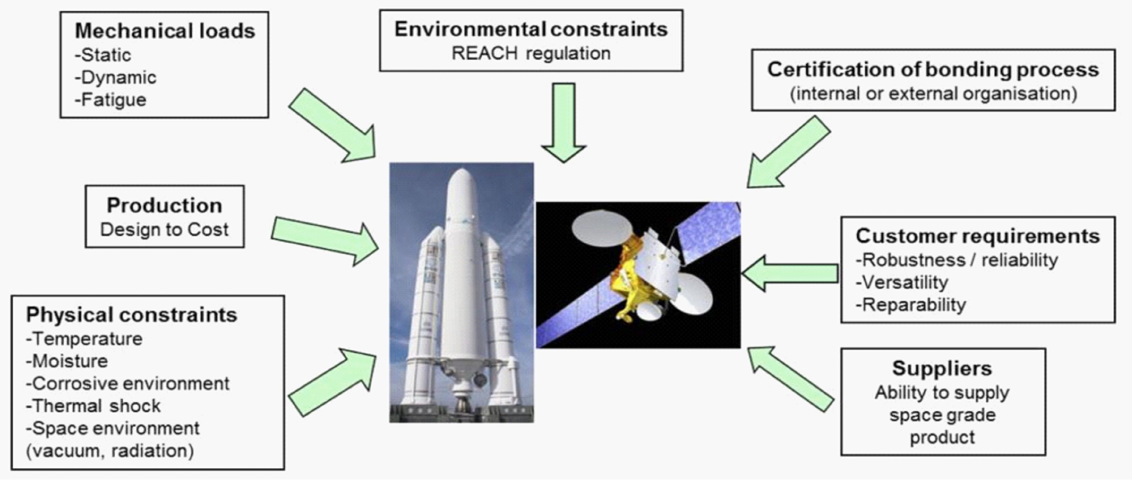 Figure 41: Overview of the constrains linked to adhesive bonds for space applications (not exhaustive)
Design of hardware
The design of bonded hardware involves parameters such as load direction and magnitude, CTEs, bonding gaps, accessibility. A detailed overview on how to design an adhesive joint can be found in sections 8 to 11 of ECSS-E-HB-32-21.
Designers or sizing engineers have a good understanding of how stresses are distributed across the joint when loads (mechanical and thermal) are applied to it. Typically they consider the general guideline for adhesive bonds to:
Maximize shear and minimize peeling and cleavage load
Maximize compression and minimize tensile loads
Optimize the bond length to width ratio for shear loading
Increase the bond width is more efficient than to increase the bond length.
In case of using fibre composite adherends the fibre orientation of the first ply is taken into account to optimize the joint performance.
Performance of the adhesive bond
After having defined the basic design of the hardware and the parts that are bonded, the analysis of the adhesive bond is performed. This analysis can focus on joint design, adhesive material properties and environmental constraints, see Figure 42.
The needed performance of the adhesive bond has an influence on the choice of the adhesive itself, regarding for example strength, curing process, surface treatment of the adherend and temperature stability.
More information on surface treatments of the adherends can be found in section 12 of ECSS-E-HB-32-21 and in ISO 17212:2012.
In case the needed performance cannot be achieved with the adhesives and surface preparations available, the design is changed to generate a more bonding-friendly setup (see Figure 42) or changed to another (for example mechanical) joining method.
Adhesive bonding process
The adhesive bonding process is considered as a “special process” in accordance with ECSS Q-ST-70 and generally taken into account in the early stages of the project.
The amount of time and personnel needed to perform the bonding depends on parameters like, the overall surface area, type of surface preparation, treatment, possible primer application, pot life and curing of the adhesive.
The bonding process steps can be described in individual procedures. For example the adhesive bonding procedure can refer to sub- procedures.
Examples of adhesive bonding process steps:
Preparation of bonded parts (degreasing, cleaning, ultrasonic bath with organic solvents, drying condition)
Surface treatment (by mechanical, chemical and physical means)
Surface post-treatment (incl. final surface cleaning, surface protection and conditions of storage if not bonded immediately)
Surface activation (by mechanical, chemical and physical means)
Adherends such as polymers can need a dedicated surface treatment to increase their surface energy.
Surface quality verification (for example surface energy, roughness, wettability)
Positioning and alignment of adherends
Adherend priming (if any)
Adhesive preparation (including conditioning and mixing)
Adhesive application
Adhesive curing in bonded assembly
Bonded assembly verification (NDI inspection after cure – visual, dimensional check, mechanical load proof test)
- 1 The same process steps are applicable for in-process samples.
- 2 This list with examples is not exhaustive and steps are not mentioned in a strict chronological order.
In the case of adherends that are sensitive to ageing in storage conditions (UV, humidity, temperature over time) a specific surface preparation process can be applied to remove the affected surface layer.
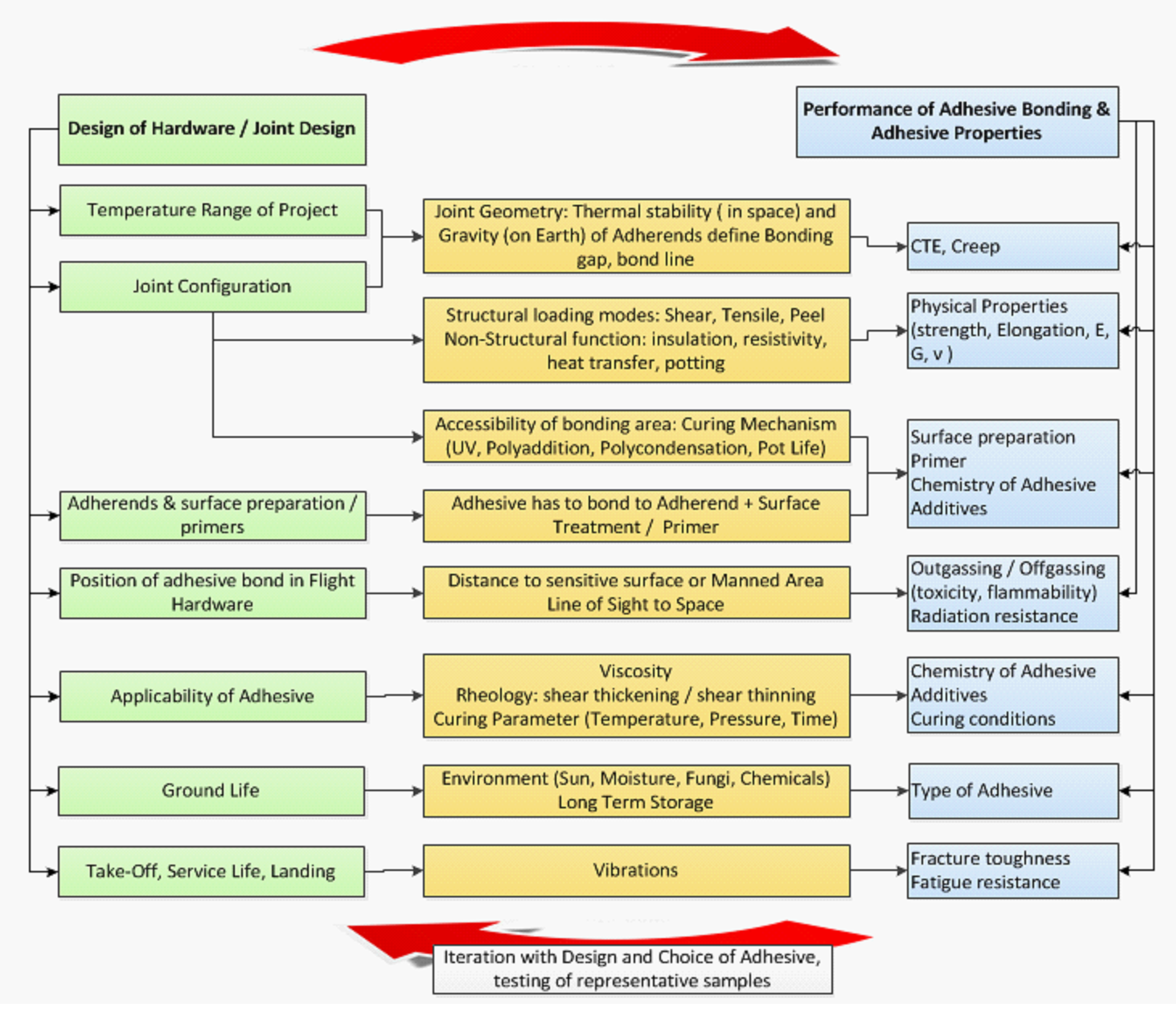 Figure 42: Overview on some parameters influencing the adhesive bond and its design
For a more detailed design chart see Figure 10.16‐1 in ECSS-E-HB-32-21.
Selection of adhesive
Overview
The selection of an appropriate adhesive depends on a wide range of factors from early stage of manufacturing over service life till the end of mission. The ECSS Adhesive Bonding Handbook ECSS-E-HB-32-21 gives information about adhesive characteristics and properties and adhesive selection.
Analysis of adhesive application
ECSS-Q-ST-70-16_1460001Selection of materials for adhesives shall be in compliance with requirements from clause 5 of ECSS-Q-ST-70.
Requirements from clause 5 of ECSS-Q-ST-70 include: for example: vacuum, radiation, moisture.
ECSS-Q-ST-70-16_1460002Selection of adhesives shall be in compliance with clause 4.2.11 of ECSS-Q-ST-70-71.
ECSS-Q-ST-70-16_1460003Depending on the cured adhesive properties, selection of adhesives shall be in compliance with requirements from clauses 4.2.17, 4.2.18 and 4.2.19 of ECSS-Q-ST-70-71.
Adhesive materials can be also grouped to elastomers (clause 4.2.17), thermoplastic (4.2.18) and thermosets (4.2.19).
ECSS-Q-ST-70-16_1460004Selection of adhesive tapes shall be in compliance with clause 4.2.12 of ECSS-Q-ST-70-71.
ECSS-Q-ST-70-16_1460005The outgassing characteristics of selected adhesive material in cured state shall be in compliance with requirements from clause 5 of ECSS-Q-ST-70-02.
For launcher applications when the adhesive material is not facing the spacecraft (for example lower stagers of launcher, ground segment support applications), the requirements on cleanliness and contamination and outgassing specified in clause 5 of ECSS-Q-ST-70-02 can be tailored.
ECSS-Q-ST-70-16_1460006An assessment of the bonding application shall be performed as basis for the adhesive selection.
ECSS-Q-ST-70-16_1460007The assessment should include, but is not limited to:
- Joints design
- Mechanical loads
- Thermo-mechanical loads
- Adherends
- Geometrical Configuration
- Shape of the bondline
- Need of NDI
- Adhesives properties
- Mechanical properties
- Thermo-mechanical properties
- Offgassing
- Moisture sensitivity
- Appearance
- Specific properties
- Processing
- Surface preparation of adherends
- Curing conditions: time to full cure, temperature, pressure, humidity, time to handling strength
- Adhesive conditioning
- Viscosity
- Pot life
- Manual or machine processing
- Adhesive filet removal (excess adhesive)
- Packaging and storage
- Ground, launch, and in-orbit environment
- Radiation
- Vacuum
- Temperature range
- Thermal cycling
- Chemical compatibility
- Storage time and storage conditions
- Procurement
- Cost factors
- Lead time
- Export control
- Obsolescence risk
- Health and safety
- 1 For requirement 5.2g.1(e): The shape of the bondline refers, for example, to the presence/absence of an outer fillet (excess glue)
- 2 For requirement 5.2g.2(d): Sensitivity can be related to water absorption, water content in the adhesive, water desorption, CME, water diffusion.
- 3 For requirement 5.2g.2(d): Accelerated hot-wet tests can be performed within screening activities in order to determine the moisture sensitivity of representative assembly.
- 4 For requirement 5.2g.2(e): Optical applications can require either transparent or dark glues.
- 5 For requirement 5.2g.2(f): Specific properties include electrical, thermal, optical, thermo-optical properties.
- 6 For requirement 5.2g.3(g)variations in adhesive processing can modify final adhesive properties
- 7 Further information about selection of adhesives can be found in section 7 of ECSS-E-HB-32-21.
ECSS-Q-ST-70-16_1460008Adhesives properties should be analysed based on: - Supplier information
- Materials data bases
- Data of tests relevant to the specific application
- 1 Examples of Materials databases are: MAPTIS (NASA), MATREX (CNES), Granta MI, ESMDB (ESA), MIL handbooks.
- 2 Examples of tests can be found in Annex D, Annex E and section 15 of ECSS-E-HB 32-21.
- 3 Further information on adhesive characteristics and properties can be found in a section 6 of ECSS-E-HB-32-21.
- 4 Tests applied for generation of missing data are based on national or international standards, list of tests can be found in Annex D, Annex E.
ECSS-Q-ST-70-16_1460009For application of adhesive tape for passive thermal control requirements from clause 4 of ECSS-Q-ST-70-09 shall apply for thermo-optical measurements.
Tape application procedure can have an impact on the tape thermo-optical properties.
Definition of adhesive bonding process
Adhesive bonding process requirements
ECSS-Q-ST-70-16_1460010The adhesive bonding process shall be in compliance with the requirements specified as in clause 4.3.1 of ECSS-Q-ST-70-71.
ECSS-Q-ST-70-16_1460011Process control of adhesive bonding shall be performed in compliance with the requirements from clause 7 of ECSS-Q-ST-70.
ECSS-Q-ST-70-16_1460012The adhesive bonding process shall be performed according to the adhesive bonding procedure specified in DRD Annex A.
ECSS-Q-ST-70-16_1460013Adherends and adhesive materials shall have the same temperature as the processing environment in order to avoid condensation during the bonding process.
- 1 This means conditioning to the working temperature of materials taken from colder or warmer places than the bonding area.
- 2 This can be described by an additional step: conditioning prior to bonding.
Adhesive bonding procedure
ECSS-Q-ST-70-16_1460014An adhesive bonding procedure shall be issued by the supplier according to DRD Annex A.
- 1 Preparation of the bonding procedure is considered as a multidisciplinary task.
- 2 The bonding procedure can be a single document or split into several documents.
ECSS-Q-ST-70-16_1460015The references relevant to adhesive bonding procedure shall be listed in the Declared Process List (DPL)
ECSS-Q-ST-70-16_1460016The operators executing the bonding process shall proceed according to the adhesive bonding procedure.
ECSS-Q-ST-70-16_1460017Training of the operators shall be done in accordance to the requirements in clause 8.11.
Adhesive bonding process traceability
ECSS-Q-ST-70-16_1460018For process traceability the requirements from clause 5.2.5 of ECSS-Q-ST-20 shall apply.
ECSS-Q-ST-70-16_1460019Date of the bonding process steps shall be recorded.
ECSS-Q-ST-70-16_1460020Batch (production lot) number of primer and adhesive material used for bonding process shall be recorded.
ECSS-Q-ST-70-16_1460021Operator identification shall be recorded.
ECSS-Q-ST-70-16_1460022Records of requirements 6.3b, 6.3c and 6.3d shall be kept in the manufacturing file.
For requirement 6.3b the information about the execution time for bonding process steps can be useful.
Verification of adhesive bonding
Overview
The adhesive bonding of the flight hardware needs a careful analysis to determine its verification status with respect to the mission requirements. When verification is missing or not complete then a test plan is established.
The test plan is defined - to verify the performance of the flight hardware. Defined tests are therefore representative of flight conditions with, for example, representative loads being applied in representative directions.
Adhesive bonding test plan
ECSS-Q-ST-70-16_1460023The supplier shall issue an adhesive bonding test plan according to the DRD in Annex B for customer approval for critical processes as defined in ECSS-Q-ST-70.
Customer approval is processed through a RFA.
ECSS-Q-ST-70-16_1460024The adequacy and reliability of a bonding configuration and its associated process shall be demonstrated through a verification programme.
A bonding configuration is defined as a minimum by the adherends, the adhesive and the bonding process, see clause 7.7.
ECSS-Q-ST-70-16_1460025Adhesive bonding performance properties to be tested shall be selected according to application needs.
- 1 The bonding application assessment as described in clause 5.2 can be used to determine these parameters.
- 2 The test item configuration is linked to the properties to be characterized.
ECSS-Q-ST-70-16_1460026In the adhesive bonding test plan the supplier shall list all tests and inspections used during sub-sequential steps of verification test sequence in conformance with requirements from clause 7.7.
ECSS-Q-ST-70-16_1460027The pass-fail criteria of the verification test sequence shall be specified by the supplier and submitted as part of the adhesive bonding test plan for customer approval.
Adhesive bonding test report
ECSS-Q-ST-70-16_1460028The results of the test shall be documented in the adhesive bonding test report in conformance with the DRD from Annex C.
Test item bonding procedure
ECSS-Q-ST-70-16_1460029The bonding procedure shall be in compliance with the DRD from Annex A.
ECSS-Q-ST-70-16_1460030The bonding procedure used for test item shall be representative of flight hardware manufacturing.
ECSS-Q-ST-70-16_1460031Any deviation between test items and flight hardware bonding procedure shall be justified and submitted for the customer approval.
Deviations can be related to differences in adhesive application, tooling manufacturing environment and to upscaling of in production.
Test item configuration
ECSS-Q-ST-70-16_1460032Test items shall be representative of flight hardware configuration as a minimum for the following:
- Adhesive preparation and curing
- Adhesive application
- Primer preparation and curing
- Primer application
- Adherend materials
- Adhesive thickness
- Surface finishing of adherends
- Geometry
- Dimensions
- Surface preparation
- 1 to item 7.5a.5: The precise chemical composition and material manufacturing process can be important for any type of material.
- 2 to item 7.5a.7: Surface finishing is state of the surface before surface preparation prior adhesive bonding.
ECSS-Q-ST-70-16_1460033Any deviation between test items and flight hardware configuration shall be justified and submitted for customer approval.
The justification rational can be included in the adhesive bonding test plan.
ECSS-Q-ST-70-16_1460034Deviations in test item from flight hardware shall be justified for following:
- Adherends materials
- Adhesive preparation method
- Adhesive application
- Adhesive thickness
- Curing cycle
- Surfaces finishing of adherends
- Geometry
- Dimensions
- Sandwich panel configuration
- Surface preparation ECSS-Q-ST-70-16_1460035In case a repair process of adhesive bond exists, the test items shall be manufactured and tested according to the verification sequence.
Typical examples of repairs are : debonding/breakage of MLI studs, bonding of additional fixtures in cabling.
Test item identification
ECSS-Q-ST-70-16_1460036The supplier shall mark all test items with identification to maintain traceability in a way not to degrade the quality of the test item during testing.
This includes also untested spare test items.
ECSS-Q-ST-70-16_1460037The supplier shall maintain the traceability of the following details of the test items submitted for testing:
- Identification code of the test item
- Applicable documentation
- Details of the supplier of the assembly
- Type of product
- Adherend and adhesive materials
- Processing details, reference to the adhesive bonding procedure
- Batch numbers
- Test item quantity
- Test item manufacturing date
- Prepared by
- Any deviation to test item definition
Verification test sequence
General
ECSS-Q-ST-70-16_1460038For the purpose of the verification test sequence the supplier shall identify the parameters affecting the performance of the adhesive bond within its life cycle.
Figure 42 shows some parameters from the on ground-life phase, pre-launch, launch and early orbit phase as well as the mission.
ECSS-Q-ST-70-16_1460039The verification test sequence shall be in accordance with the flow chart from Figure 71.
- 1 The verification sequence based on the flow chart from Figure 71 can be tailored depending on the application needs. For example it is not always necessary to have intermediate verification steps (Set of Test Items “2” tested after on-ground exposure simulation test and “3” tested after launch environmental exposure can be optional, represented by dashed lines with arrows in Figure 71).
- 2 The need to perform optional steps in Figure 71 is discussed in clauses 7.10 and 7.11.
ECSS-Q-ST-70-16_1460040After each environmental exposure step, inspection of the test item set should be performed.
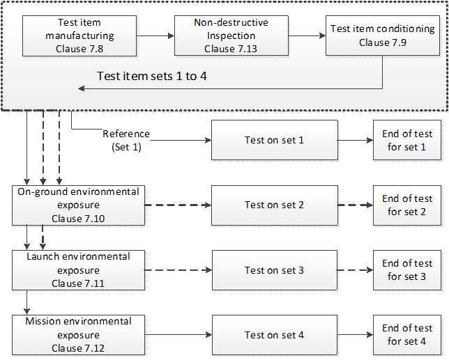 ECSS-Q-ST-70-16_1460133Figure 71: Flow chart with adhesive bonding verification sequence
Test item manufacturing
ECSS-Q-ST-70-16_1460041Test items shall be manufactured in accordance with requirements from clause 7.5.
ECSS-Q-ST-70-16_1460042The number of test items in a test item set shall be as a minimum five.
ECSS-Q-ST-70-16_1460043The number of test items may be reduced upon customer agreement.
ECSS-Q-ST-70-16_1460044For the determination of design allowables the number of test items shall be agreed with the design authority.
ECSS-Q-ST-70-16_1460045The test items sets should originate from the same test item population.
For 7.8d for the determination of design allowables refer to clauses 4.5.8 and 4.5.12 from ECSS-E-ST-32.
Test item conditioning
ECSS-Q-ST-70-16_1460046Any conditioning step performed on flight hardware shall be applied to test items.
Examples of conditioning steps are:
- Heat treatments performed in manufacturing steps after bonding
- Bake-out
- Thermal cycling performed in screening activities
- Conditioning between environmental exposure and performance test
ECSS-Q-ST-70-16_1460047Thermal cycling tests performed as conditioning steps specified in requirement 7.9a may be combined with simulation of mission environmental exposure specified in the requirements from clause 7.12.
Simulation of on-ground environmental exposure
ECSS-Q-ST-70-16_1460048The supplier shall demonstrate the robustness of the adhesive bonding in the relevant on-ground environment.
- 1 Relevant on-ground environment is the environment representative of the exposure period between bonding and launch.
- 2 Exposure to humidity or other chemical substances can contribute to the degradation of the adhesive bond.
ECSS-Q-ST-70-16_1460049On-ground robustness demonstration may be based on experience, adhesive bonding process heritage or test.
The term heritage is defined in Table 5-1 of ECSS-E-ST-10-02.
ECSS-Q-ST-70-16_1460050For launcher applications the hot-wet exposure shall be part of the verification sequence of structural bonds.
For a list with examples of conditioning and durability standards see Table F-4 and Table F-5 respectively.
ECSS-Q-ST-70-16_1460051For spacecraft applications the sensitivity to atmospheric humidity shall be assessed.
- 1 Sensitivity of an adhesive bond’s performance to humidity can be interpreted as negative impact on the key property: for example mechanical, electrical, dimensional, thermo-optical properties.
- 2 For criticality of the adhesive bonding application see Table F-1.
- 3 For the sensitivity assessment of adhesive bonds to humidity see Table F-2.
- 4 Necessity to implement the hot-wet exposure into the verification sequence can be found in Table F-3.
ECSS-Q-ST-70-16_1460052For spacecraft applications exposed to cleanroom-controlled environments the hot-wet exposure need not to be always performed. - 1 Cleanroom-controlled environments are defined in ECSS-Q-ST-70-01, with temperature in the range of (22 ± 3) °C, and relative humidity (55 ± 10) %.
- 2 Examples of humidity highly-sensitive, sensitive and non-sensitive applications are presented in Table F-2.
- 3 An example of assessment for necessity to implement the hot-wet exposure into the verification sequence can be found in Table F-3.
ECSS-Q-ST-70-16_1460053In case the hot-wet exposure is performed, the temperature, relative humidity and duration of the exposure shall be agreed with the customer.
Examples of conditioning and durability standards are given in Table F-4.
ECSS-Q-ST-70-16_1460054For the hot-wet exposure specified in 7.10f water condensation on the test item shall be prevented.
- 1 An efficient way to avoid condensation is to increase the relative humidity only after the test items are at the given exposure temperature.
- 2 An inclined cover can help prevent condensed water accidentally dropping down onto the test items from the ceiling of the test chamber.
ECSS-Q-ST-70-16_1460055For the hot-wet exposure specified in 7.10f purified water of a quality ISO Grade II, or better, as defined in ISO 3696:1987 or equivalent, should be used.
The detailed water purity can be also found in ASTM D1193-06:2011.
Simulation of launch environmental exposure
Overview
Launch environmental exposure means mechanical loads, thermal exposure or a combination of both, that act on the flight hardware during launch.
Test definition
ECSS-Q-ST-70-16_1460056Launch environment test conditions shall be agreed with the customer.
ECSS-Q-ST-70-16_1460057Launch environment test conditions should be derived from system level requirements.
ECSS-Q-ST-70-16_1460058Thermal exposure relevant to launch phase may be combined with simulation of mission environmental exposure.
ECSS-Q-ST-70-16_1460059Mechanical load testing may consist of:
- Static and quasi-static load testing
- Dynamic load testing: sinus, random, acoustic
- Shock testing.
Dynamic mechanical load testing at test item level is usually not necessary. It is generally performed when adhesive bonds are submitted to complex loads which are difficult to model.
Simulation of mission environmental exposure
Overview
In-orbit environmental exposure is mainly related to thermal vacuum cycling of the adhesive bond.
In special applications, radiation (UV, electrons, protons) tests, ATOX tests as well as long-term exposure to high or cold temperatures can be necessary. Tests are generally performed in the frame of a dedicated verification test flow.
- 1 Radiation testing is addressed in ECSS-Q-ST-70-06.
- 2 Thermal cycling tests are not applicable for launchers except of in-orbit upper parts.
Thermal cycling test conditions
ECSS-Q-ST-70-16_1460060Thermal cycling test conditions shall be agreed with the customer.
Test conditions are e.g. thermal range, number of cycles, atmosphere.
ECSS-Q-ST-70-16_1460061A minimum of 25 thermal cycles shall be performed.
- 1 Generally 25 cycles cover on ground thermal cycling testing at unit level with margin.
- 2 ECSS-Q-ST-70-04 can be used as a guideline.
- 3 The atmosphere in the test chamber can have an impact on adhesive joint performance.
ECSS-Q-ST-70-16_1460062For ambient pressure thermal cycling water condensation shall be avoided.
An inert gas atmosphere can be used to avoid water condensation and prevent oxidation.
ECSS-Q-ST-70-16_1460063As a minimum the first five thermal cycles shall be performed in vacuum for vacuum sensitive configurations.
Vacuum sensitive configurations include but are not limited to:
- Adhesive tapes
- Foil heaters
- Thin or flexible adherends
- Radiator foils
- Solar reflectors
- Any assembly crossing Tg temperature of its adhesive material during the thermal cycling
- Assemblies for which moisture desorption has an impact on the bonding performance (CME effect)
ECSS-Q-ST-70-16_1460064Thermal vacuum cycling may be omitted in case the robustness of the adhesive bonding to thermal vacuum can be demonstrated by experience from former projects.
Thermal vacuum experience can be gained by unit level testing, spacecraft level testing, flying heritage, sample level testing
ECSS-Q-ST-70-16_1460065In addition to requirement 7.12.2b additional thermal cycles shall be performed to cover mission lifetime.
- 1 The additional thermal cycles are typically performed to simulate ageing effects (thermo-chemical, creep and fatigue phenomena).
- 2 The additional thermal cycles can contain long term thermal endurance exposure, for example cruise phases of probes.
ECSS-Q-ST-70-16_1460066For thermal vacuum cycles, the pressure level shall be less than 1 Pa (10-2 mbar).
ECSS-Q-ST-70-16_1460067For thermal vacuum cycling, the pressure shall be recorded.
ECSS-Q-ST-70-16_1460068The temperature range shall cover the mission qualification thermal requirements.
Mission specific qualification temperature for the bonding, taking into account all phases on ground, launch and during the mission.
ECSS-Q-ST-70-16_1460069Heat generating adherends should be powered in their mission operational temperature range to replicate the thermal loads at the joint in vacuum.
This is related to potential additional temperature loads on the joint, due to limited temperature conductance of the adherends.
ECSS-Q-ST-70-16_1460070Temperature extremes shall be maintained during the dwell time within the intervals Tmax -0/+5 °C and Tmin +0/-5 °C.
ECSS-Q-ST-70-16_1460071The minimum dwell time at each temperature extreme, as measured on the test items, shall be not less than five minutes.
ECSS-Q-ST-70-16_1460072The heating and cooling rate should be less than 12 °C per minute.
- 1 Maximum rate is specified in order to avoid thermal shock.
- 2 A high heating or cooling rate can induce unwanted thermal gradients and hence increase thermo-elastic stresses.
- 3 The temperature rate can be tailored in case of thermal shock simulation.
ECSS-Q-ST-70-16_1460073The test item temperature shall be recorded to verify that the specified temperature is achieved.
ECSS-Q-ST-70-16_1460074The temperature sensor should be placed as close as possible to the adhesive bond.
An additional test item, slightly modified to accommodate a temperature sensor, can be used if it is not possible to place a sensor directly on the verification test item.
Inspection before, during and after environmental exposure
ECSS-Q-ST-70-16_1460075The supplier shall perform the inspection according to requirements in clause 8.10.
Test before, during and after environmental exposure
ECSS-Q-ST-70-16_1460076Test of test item set shall be performed according to adhesive bonding test plan specified in the 7.2.
- 1 Examples of tests are included in Annex D and Annex E.
- 2 The monitoring of the functional performance of the test items can be important: for example infrared monitoring of foil heaters during thermal vacuum exposure; temperature measurement of bonded thermistors, thermo-optical performance of thermal control materials, electrical performance.
ECSS-Q-ST-70-16_1460077For mechanical test samples static performance test shall be performed at least for test item sets 1 and 4.
Examples of standard mechanical tests are given in Annex E.
Quality assurance
Overview
The role of quality assurance in adhesive bonding is to ensure that:
Materials stipulated in the design are obtained, stored and used correctly; as stated in the procurement specification and confirmed by incoming inspection.
Each joint made meets the materials and process specification(s) and is fully documented, test data are accumulated and that the bonded structure is qualified for space use,
Bonded‐joint data acquired from testing, inspection or in‐service experience are ‘fed‐back’ into manufacturing documentation. Previously accumulated data can aid the design process for all subsequent, similar, structures.
The performance of adhesive bonds is strongly linked to the application and strict control of every manufacturing process step. Adequate training, along with regular monitoring and documentation, of personnel involved in any bonding‐related process is an essential part of the quality assurance system.
Besides all the materials and processes needed for the adhesive bonding, the training of personnel is a key factor for successful adhesive bonding. There are many possible causes for human error like for example bad mixing, exceeding of pot life, insufficient surface preparation and many more.
General information regarding quality control of adhesive bonding can be found in section 14 of ECSS-E-HB-32-21.
General
ECSS-Q-ST-70-16_1460078The quality assurance requirements specified in clause 5 of ECSS-Q-ST-20 shall apply.
Procurement
ECSS-Q-ST-70-16_1460079Procurement of all materials needed for adhesive bonding shall be in conformance with clause 5.6.1 of ECSS-Q-ST-70.
Materials to be considered are for example raw materials, adhesives, filler materials, as well as adherends manufactured and pre-treated (for example plated, conversion coated) for bonding.
ECSS-Q-ST-70-16_1460080The user shall request the information about change of material composition, material testing and stop of production from material supplier.
- 1 Further information on possible parameters to be checked can be found in section 14.4 of ECSS-E-HB-32-21.
- 2 Technical Data Sheets (TDS) and Safety Data Sheets (SDS) can undergo changes because of obsolescence, production variation over the years or new information about the material.
Hazard, health and safety precautions
ECSS-Q-ST-70-16_1460081The supplier shall identify, manage and process materials and parts with hazardous characteristic according to requirements from clause 5 to clause 8 of ECSS-Q‐ST‐40.
ECSS-Q-ST-70-16_1460082The supplier shall keep the health and safety precautions according to the supplier’s national safety regulations.
ECSS-Q-ST-70-16_1460083The details of hazards for each material used in the process shall be known to all personnel involved in the application.
ECSS-Q-ST-70-16_1460084Operators and supervising staff shall have access to the Material Safety Data Sheets of the materials that are used in the adhesive bonding process.
ECSS-Q-ST-70-16_1460085Hazards to personnel, equipment, environment and materials shall be controlled and reduced to the risk specified in supplier’s in-house procedures.
Hazards can be reduced by using personal protective equipment (PPE).
Incoming inspection
ECSS-Q-ST-70-16_1460086All materials used in adhesive bonding process shall be submitted to an incoming inspection.
ECSS-Q-ST-70-16_1460087Incoming inspection shall be performed on each batch in compliance with clause 5.4.4. from ECSS-Q-ST-20.
ECSS-Q-ST-70-16_1460088In-coming inspection may include:
- Check of material reference
- Transportation and packing conditions
- Surface finish of adherends
- Expiry dates of adhesive components and primers
- Expiry date of applied surface treatments
- Visual criteria
- Chemical composition
- Microstructural analysis of adherends
- Crosscheck of relevant properties stated in certificate of analysis (CoA) of adhesive materials with results of in-house analysis.
Further information on possible parameters to be checked can be found in section 14.4 of ECSS-E-HB-32-21.
Traceability
ECSS-Q-ST-70-16_1460089Traceability of materials shall be handled in conformance with clause 5.7.2 of ECSS-Q-ST-70.
ECSS-Q-ST-70-16_1460090Supplier executing the bonding process shall establish a control system to verify before use the validity of the involved materials with limited shelf life in compliance with requirements from clause 4 of ECSS-Q-ST-70-22.
- 1 This applies for surface treatment agents, adhesives, additives, primers, sealants or potting compounds.
- 2 The shelf life can be reduced after opening the material’s original package or container.
ECSS-Q-ST-70-16_1460091Traceability of the bonding processes shall be performed in accordance with clause 6.3.
ECSS-Q-ST-70-16_1460092Traceability of the bonding inspection shall be recorded in the manufacturing file.
Tooling and equipment control
ECSS-Q-ST-70-16_1460093The supplier shall ensure that manufacturing equipment and tooling has no detrimental effect on the bonding process.
For example cleanliness provisions, no contamination with unwanted chemicals, no visual defects
ECSS-Q-ST-70-16_1460094Calibration control shall comply with the requirement from clause 5.2.6 of ECSS-Q-ST-20.
ECSS-Q-ST-70-16_1460095The supplier shall ensure that all automated adhesive application systems are calibrated.
ECSS-Q-ST-70-16_1460096Selection of tooling and equipment shall conform to the requirements from clause 5.2.6 of ECSS-Q-ST-20.
Workmanship
ECSS-Q-ST-70-16_1460097The quality of the workmanship shall be monitored.
ECSS-Q-ST-70-16_1460098Bonded assemblies shall be free of defects that affect the intended use.
For example cracks, entrapped air, kissing bonds, discoloration and particles can all affect bonding performance.
ECSS-Q-ST-70-16_1460099The supplier shall ensure quality of workmanship by implementing defined workmanship checks based on the dedicated bonding configuration.
For example check of visibility of adhesive at bond line edges, measurement of adhesive mass, control of temperature of the mixture, bond line thickness control, bonded area verification
ECSS-Q-ST-70-16_1460100The supplier shall specify adhesive bonding in-process control.
For example proof testing, in-process samples, visual inspection, adhesive cure check.
ECSS-Q-ST-70-16_1460101Adhesive bonding assembly shall not lose any macroscopic particles contributing to particulate contamination of the spacecraft.
The example of particulate release can be adhesives not covered by adherends after exposure to mechanical environment.
ECSS-Q-ST-70-16_1460102Cross-contamination between different chemical families shall be avoided.
- 1 For example cross-contamination between silicones and other adhesives, between hardener and resin pots.
- 2 Cross-contamination can be avoided for example by using dedicated tooling for different products, or by thoroughly cleaning tooling before using the next product.
- 3 Change of gloves can be useful to avoid cross contamination.
- 4 Separate rooms can be useful to avoid cross contamination between for example silicone adhesives and epoxy adhesives.
Handling and storage
ECSS-Q-ST-70-16_1460103The conditions for handling and storage of materials used in adhesive bonding process shall be available to all operators and supervising staff.
Storage conditions can be found in the Safety Data Sheets (SDS) of the used materials.
ECSS-Q-ST-70-16_1460104The test item shall only be handled with clean, powder‐free and lint‐free gloves compatible with all compounds used.
For example the chemical compatibility between solvents, cleaning agents, adhesives, primer and manufacturing tools can play an important role.
ECSS-Q-ST-70-16_1460105Test items shall be stored in a controlled area, with an ambient temperature of (22 ± 3) °C and relative humidity of (55 ± 10) %.
ECSS-Q-ST-70-16_1460106When test items are handled, contamination shall be avoided.
ECSS-Q-ST-70-16_1460107A protective material may be used to avoid contamination on sensitive surfaces.
A sensitive surface can be:
- Surface treated prior priming,
- Primed surface prior bonding,
- The fracture surface of analysed joint after functional or destructive test.
ECSS-Q-ST-70-16_1460108A protective material shall not degrade sensitive surfaces.
Particulate or molecular contamination can impair adhesion properties.
ECSS-Q-ST-70-16_1460109Use of a protective material is part of the handling procedure and shall be included in the verification sequence.
ECSS-Q-ST-70-16_1460110To avoid any damage the test items may be packed in clean, dust‐ and lint‐free material.
ECSS-Q-ST-70-16_1460111Limited‐life time materials shall be labelled with their expiry date and lot number.
ECSS-Q-ST-70-16_1460112In case the expiry date of life limited materials is not known then the supplier shall trace the date of shipment
Inspection and bonding process control
ECSS-Q-ST-70-16_1460113The supplier shall perform an inspection on all qualification and flight hardware bonding.
- 1 The inspection can be non-destructive or destructive (dedicated samples).
- 2 For large number of identical bonded joints, inspection can be performed on a sampling basis.
ECSS-Q-ST-70-16_1460114Inspection shall meet the requirements for inspection procedures from clause 4.3.16 of ECSS-Q-ST-70-71.
ECSS-Q-ST-70-16_1460115The acceptance criteria for the inspection of bonded joints shall be specified by the supplier and agreed with the customer. - 1 Depending on the process and the configuration, different acceptance criteria can be necessary.
- 2 Supplier can introduce in-process samples.
ECSS-Q-ST-70-16_1460116The inspection shall be performed by an inspector independent of the operators executing the bonding process.
ECSS-Q-ST-70-16_1460117Visual standards of bonded joints such as photos, drawings or other visual aids and clearly illustrating the quality characteristics needed should be available to each inspector. - 1 The visual standards can be examples of acceptable and unacceptable bond lines.
- 2 Typical defects can be reported in a defect catalogue.
ECSS-Q-ST-70-16_1460118Personnel involved in the inspection and non-destructive testing of adhesive bonds shall have an appropriate qualification and valid certificate. - 1 Appropriate qualification schemes of Non-Destructive Inspection can be found in ECSS-Q–ST-70-15 (For example visual inspection, Ultrasonic inspection, X-ray tomography, Microscopic inspection and other methods).
- 2 Inspection can be part of the bonding process but also an independent process.
Operator and inspector training
ECSS-Q-ST-70-16_1460119Operators performing adhesive bonding processes shall be trained and certified.
ECSS-Q-ST-70-16_1460120Inspectors for adhesive bonding shall be trained and certified.
ECSS-Q-ST-70-16_1460121Training shall be performed at an adhesive bonding school or by certified external bodies or by approved in-house instructors.
ECSS-Q-ST-70-16_1460122In-house instructors shall be nominated by the company with involvement of quality assurance responsible.
ECSS-Q-ST-70-16_1460123Training and certification may be performed according to in-house standards or external training and certification scheme
External certification scheme and certification bodies for bonding operators can be found in Annex G.
ECSS-Q-ST-70-16_1460124Training shall include at least the following points:
- Adhesive bonding process
- Complexity of configurations
- Reproducibility
- Handling of raw materials, process chemicals and equipment
- Cleanliness and contamination control of environment, materials and equipment
- Safety‐related aspects of materials and process chemicals.
Examples of complexity of configurations are complex shapes, fragile or sensitive materials, multi-step integration processes.
ECSS-Q-ST-70-16_1460125Training specified in requirements 8.11f.4, 8.11f.5 and 8.11f.6 may be implemented in a dedicated training.
ECSS-Q-ST-70-16_1460126Skills status of all operators for adhesive bonding shall be traced in suppliers’ internal system.
ECSS-Q-ST-70-16_1460127The supplier shall specify the conditions of validity of the internal training and internal certification of the bonding operators.
Re-certification can be needed in the event of a new process, a modification to an existing process or a long inactivity period.
ECSS-Q-ST-70-16_1460128The supplier shall specify the conditions of validity of the internal training and internal certification of inspectors.
Re-certification can be needed in the event of a new inspection procedure, a modification to an existing inspection procedure or a long inactivity period.
Nonconformance
ECSS-Q-ST-70-16_1460129Nonconformances shall be managed in conformance with requirements from the clause 5 and 6 of the ECSS-Q-ST-10-09 and clause 5.2 of ECSS-Q-ST-10.
ANNEX(normative) Adhesive bonding procedure – DRD
DRD identification
Requirement identification and source document
This DRD is called from ECSS-Q-ST-70-16, requirements 6.1c and 6.2a.
Purpose and objective
The purpose of this document is to provide a detailed adhesive bonding procedure containing all steps necessary to perform adhesive bonding.
Expected response
Scope and content
ECSS-Q-ST-70-16_1460130The following adhesive bonding parameters shall be documented in the adhesive boding procedure:
- List of adherend, adhesive and primer materials
- List of equipment to be used during overall bonding process
- Environmental working conditions
- Positioning and blank mating of adherends to be bonded, dimensional verification
- Surface preparation of adherends
- Definition of time delay between surface preparation and execution of bonding
- Storage conditions after surface preparation of adherends
- Preparation of primer
- Preparation of adhesive
- Means of application of adhesive
- Fixture load or pressure applied during curing
- Curing schedule, including temperature, dwell time
- Adhesive bonding process control
- 1 to item A.2.1a.3: Examples of environmental working conditions are relative humidity, temperature, pressure and cleanliness of work place.
- 2 to item A.2.1a.5: surface preparation include cleaning, sanding, chemical treatments, priming.
- 3 to item A.2.1a.6: surface chemistry of adherend parts can evolve within few hours after surface preparation.
- 4 to item A.2.1a.8: preparation of primer includes mixing ratio, pot life, evaporation or curing time.
- 5 to item A.2.1a.9: preparation of adhesive includes mixing ratio, pot life, degassing of the mixture.
- 6 to item A.2.1a.10: means of application of adhesive are for example airbrush, foil adhesive roller or dispenser, brush, syringe, spatula, injector.
- 7 to item A.2.1a.12: heating and cooling rates can be key parameters for some type of adhesive systems.
- 8 to item A.2.1a.12: the minimum time for safe handling can be different compared to full curing.
- 9 to item A.2.1a.13: for contents refer to clauses 8.10and 8.11
Special remarks
None.
ANNEX(normative) Adhesive bonding test plan - DRD
DRD identification
Requirement identification and source document
This DRD is called from ECSS-Q-ST-70-16, requirement 7.2a.
Purpose and objective
The purpose of this document is to provide a detailed adhesive bonding test plan containing all steps necessary to perform the verification of the adhesive bonding process.
Expected response
Scope and content
ECSS-Q-ST-70-16_1460131The adhesive bonding test plan shall contain the following information
- Test objective
- Test items
- Adhesive and adherend materials
- Representativeness of test items vs flight configuration
- Reference to the adhesive bonding procedure in conformance with DRD in Annex A
- Number of test sets and test items quantity in each set
- Verification Test sequence
- List and designation of test item sets
- Applicable test procedures
- Applicable test standards
- Applicable inspection procedures
- Sequence of consecutive exposures
- Inspections performed during verification sequence on each item set
- Pass-fail criteria
Special remarks
None.
ANNEX(normative) Adhesive bonding test report -DRD
DRD identification
Requirement identification and source document
This DRD is called from ECSS-Q-ST-70-16, requirement 7.3a
Purpose and objective
The purpose of this document is to provide a detailed adhesive bonding test report containing all steps performed for the verification of the adhesive bonding process including all obtained results and conclusions of the test.
Expected response
Scope and content
ECSS-Q-ST-70-16_1460132The adhesive bonding test report shall contain the following information
- Test objective
- Reference to the applicable adhesive bonding test plan in conformance with DRD in Annex B
- Test items
- Adhesive and adherend materials
- Representativeness of test items vs flight configuration
- Reference to adhesive bonding procedure in conformance with DRD in Annex A
- Number of individual test items and test item sets tested during verification test sequence
- Verification test sequence
- List and designation of test item sets
- Applicable test procedures
- Applicable test standards
- Applicable inspection procedures
- Sequence of consecutive exposures and inspections performed during verification sequence on each item set
- Individual test item test results
- List of nonconformances
- Status of the process verification and definition of the process validity
Reference for adhesive bonding procedure can include the reference to record from manufacturing of bonded assembly or to manufacturing report.
Special remarks
None.
ANNEX(informative)Examples of techniques used for adhesive material characterization (bulk)
Overview
This Annex presents a list of analytical methods and associated test standards which can be used to characterize bulk adhesive properties. These properties are suitable in order to select the best adhesives candidates for use at a dedicated bonding assembly.
The list of recommended test standards is given in the Table D-1 is not exhaustive. Relevant test standards can be found in ECSS-E-HB-32-21 Table 15.1-2 and the book written by G. Habenicht, 2009.
Rheology
Viscosity evaluation is of prime concern for manufacturing and for quality control in transfer of liquid adhesives.
Viscosity of paste adhesive in uncured conditions can be evaluated by any appropriate means relevant to the bonding application.
-
1 For bonding in vertical positions, the viscosity of adhesive can play an important role.
-
2 If found relevant the injection capability can be evaluated.
Viscosity is useful to determine the ability of the adhesive to be injected or to be dispensed. -
1 For some dispensing systems it is important to take also the thixotropic characteristic into account.
-
2 Some adhesive manufacturers determine the product’s “pot life” as the duration after which the viscosity is twice the initial one.
-
3 Determination of the viscosity is of primary concern w.r.t. manufacturing constraints.
-
4 It is also important to determine gel point and pot life.
The following standards can be used for rheological measurements :
EN 12092:2001 Adhesives. Determination of viscosity
ASTM D 1824-16 Standard Test Method for Apparent Viscosity of Plastisols and Organosols at Low Shear Rates
ISO 11443:2014 Plastics -- Determination of the fluidity of plastics using capillary and slit-die rheometers
ISO 2555:2018 Plastics — Resins in the liquid state or as emulsions or dispersions — Determination of apparent viscosity using a single cylinder type rotational viscometer method
ISO 2535:2001 Plastics — Unsaturated-polyester resins — Measurement of gel time at ambient temperature
Rheological test methods exist to determine the G’ G’’ crossing point to assess workability times, gel-points, evolution of complex viscosity during RT curing, thermally-accelerated curing (see Table D-1).
Adhesive density and shrinkage
Adhesive volume shrinkage due to polymerisation can be evaluated by the difference of density between the uncured and cured adhesive.
The following standard can be used:
ISO 1183-1:2019 Plastics — Methods for determining the density of non-cellular plastics — Part 1: Immersion method, liquid pycnometer method and titration method
ISO 3521:1997 Plastics — Unsaturated polyester and epoxy resins — Determination of overall volume shrinkage
Note: thermal vacuum exposure can enhance overall shrinkage by “outgassing” effects by losing mass; for outgassing see D.4.
Outgassing
Screening outgassing tests provide the following values:
Total Mass Loss (TML)
Recovered Mass Loss (RML)
Collected Volatile Condensable Material (CVCM)
These data are mandatory and need to be provided when an organic material is intended to be used for a space vacuum application (on orbit or in ground inside vacuum facilities).
The screening outgassing test methods and generic acceptance criteria are covered in ECSS-Q-ST-70-02.
Sometimes kinetic outgassing parameters are needed for cleanliness sensitive applications, associated test methods can be found in ECSS-Q-TM-70-52.
The adhesive materials are tested in such conditions which are representative of the flight hardware. For example a two-component epoxy adhesive is tested after curing process representative to flight hardware application.
Differential Scanning Calorimetry (DSC)
Differential Scanning Calorimetry (DSC) analysis can be used on non-polymerized product and on polymerized product.
On non-polymerized product, DSC analysis provides polymerisation enthalpy (generally exothermic). This can be useful:
To compare or optimize curing schedule (temperature and duration),
In case of extension of product shelf life.
On polymerized product, DSC analysis allows to:
Quantify potential residual polymerisation enthalpy (not fully cured product),
determine glass transition temperature (Tg), melting temperature (Tm),
Evaluate the product degradation temperature.
The following standards can be used for DSC measurements:
ISO 11357-2:2013 Plastics - Differential scanning calorimetry (DSC) - Part 2: Determination of glass transition temperature and glass transition step height
ASTM D3418-15 Transition Temperatures of Polymers By Differential Scanning Calorimetry
For other suitable standards see Table D-1
Thermogravimetric analysis (TGA)
To determine thermo-chemical stability of individual components in uncured state, mixed, multicomponent adhesives under curing conditions or cured adhesive materials.
Thermogravimetric Analysis (TGA) allows measurement of:
Product Mass loss
Product degradation temperature
The following standards can be used for TGA measurements:
ISO 11358-1:2014 Plastics - Thermogravimetry (TG) of polymers - Part 1: General principles
ISO 11358-2:2014 Plastics -- Thermogravimetry (TG) of polymers -- Part 2: Determination of activation energy
For other suitable standards see Table D-1
TGA can be coupled with other analytical techniques (for example FTIR or GC-MS) to analyse thermally evolved products.
Dilatometry and Thermomechanical Analysis (TMA)
Dilatometry or TMA is suitable for the determination of:
Coefficient of Thermal Expansion (CTE)
Glass transition temperature (Tg)
Dimensional stability of the polymers
The following standards can be used for TMA measurements:
ISO 11359-2:1999 Plastics — Thermomechanical analysis (TMA) — Part 2: Determination of coefficient of linear thermal expansion and glass transition temperature
ASTM D696 - 16 Standard Test Method for Coefficient of Linear Thermal Expansion of Plastics Between −30°C and 30°C with a Vitreous Silica Dilatometer
For other suitable standards see Table D-1
Dynamic Mechanical Analysis (DMA)
Dynamic Mechanical Analysis (DMA) can be performed under several mechanical loading modes :
Tensile
Compression
3 point bending
Shear and other modes
The following properties can be determined:
Glass transition temperature (Tg)
Young's Modulus
Coulomb's Modulus (shear modulus)
Damping Factor
The ASTM D4065-12 Standard Practice for Plastics: Dynamic Mechanical Properties: Determination and Report of Procedures, can be used for DMA measurements.
For other suitable standards see Table D-1
Tensile strength and Young's modulus
Tensile strength testing on adhesive dog-bone shaped samples allow the measurement of:
Young's modulus
Yield strength (elastic limit)
Ultimate tensile strength
Elongation at break
Poisson ratio
Suitable test standards: ISO 527-1:2019 Plastics - Determination of tensile properties -- Part 1: General principles, ISO 527-2:2012 Plastics - Determination of tensile properties - Part 2: Test conditions for moulding and extrusion plastics, ASTM D638-14 Standard Test Method for Tensile Properties of Plastics
Other techniques for the determination of the tensile strength and modulus are often used, where the adhesive material is cured in test joint or assembly configuration, see in Table E-1 of Annex E.
Shear strength and shear modulus (adhesive material)
To address the shear properties in bulk, the materials are tested in non-bonded configuration. Dedicated tests serve to determine the bulk shear properties of the polymer:
Shear elastic modulus
Shear strength
Elongation at break
ASTM E143-13 Standard Test Method for Shear Modulus at Room Temperature
Other techniques for determination of the shear strength and shear modulus are often used, where the adhesive material is cured in test joint or assembly configuration, see Table E-1 of Annex E
Compression strength and modulus
To address the compression properties in the bulk, the materials are tested in non-bonded configuration. Dedicated tests serve to determine the bulk compression properties of the polymer:
Compression elastic modulus
Compression strength
Deformation at break
ASTM D 695-15 Standard Test Method for Compressive Properties of Rigid Plastics
Other techniques for determination of the compression properties can be used, where the adhesive material is cured in test joint assembly configuration, see in Table E-1 of Annex E
Electrical resistivity
Electrical resistance measurement allows to determine :
Surface electrical resistance or resistivity and so respectively surface electrical conductivity
Volume electrical resistance or resistivity and so respectively volume electrical conductivity
The following standards can be used :
ASTM D257-14 Standard Test Method for DC Resistance or Conductance of Insulating Materials
ASTM D4496-13 Standard Test Method for DC Resistance or Conductance of Moderately Conductive Materials
Thermal conductivity
Thermal resistance measurement allows to determine volume thermal resistance or resistivity and so respectively volume thermal conductivity
The following standards can be used:
ASTM C17713 Standard Test Method for Steady-State Heat Flux Measurements and Thermal Transmission Properties by Means of the Guarded-Hot-Plate Apparatus
ASTM� D593017 Standard Test Method for Thermal Conductivity of Plastics by Means of a Transient Line-Source Technique
For other suitable standards see Table D-1
Thermo-optical properties
Thermo-optical properties are the following:
Solar absorptance
Infra-red emissivity
These properties are necessary in thermal analysis models if thermal radiative exchanges are not negligible. ECSS-Q-ST-70-09: Measurements of Thermo-Optical Properties of Thermal Control Materials provides different test methods that can be used.
Transmittance
Transmittance measurement can be necessary for bonding in optical systems.
The following standards can be used :
ISO 15368:2001 Optics and optical instruments -- Measurement of reflectance of plane surfaces and transmittance of plane parallel elements
ASTM D1746–15 Standard Test Method for Transparency of Plastic Sheeting
Water absorption
Methods cover the determination of the relative rate of absorption of water by plastics when immersed. The following standards can be used:
ASTM D57098(2010)e1 Standard Test Method for Water Absorption of Plastics
ISO 62:2008 Plastics — Determination of water absorption
ASTM D5229/D5229M–14 Standard Test Method for Moisture Absorption Properties and Equilibrium Conditioning of Polymer Matrix Composite Materials
Table: Summary of relevant test standards for determination of bulk properties of adhesive material
|
Type of technique or material property
|
Relevant standards
|
|
Rheological measurements
|
EN 12092:2001, ASTM D1824-16, ISO 11443:2014, ISO 2535:2001, ISO 2555:2018 ISO 6721-10:2015
|
|
Adhesive Shrinkage and density
|
ISO 1183-1:2019, ISO 3521:1997
|
|
Outgassing
|
ECSS-Q-ST-70-02, ASTM E595-15, ECSS-Q-TM-70-52
|
|
DSC techniques (Glass transitions, phase transition temperature)
|
ISO 11357-2:2013, ASTM D3418-15, ISO 11357-1:2016, ISO 11357-3:2018, ISO 11357-4:2014, ISO 11357-5:2013
|
|
Thermo-chemical stability (TGA)
|
ASTM E1131-08(2014), ISO 11358-2:2014, ISO 11358-1:2014
|
|
Thermo-mechanical (CTE by TMA or dilatometer)
|
ISO 11359-2:1999, ISO 11359-1:2014, ISO 11359-3:2002, ASTM D696-16, ASTM E831-03, ASTM E2113-04
|
|
Thermo-elastic properties (DMA)
|
ASTM D4065-12, ISO 6721-1:2011
|
|
Tensile properties
|
ISO 527-1:2012, ISO 527-2:2012, ASTM D638-14
|
|
Shear strength and modulus
|
ASTM E143-13
|
|
Compression strength and modulus
|
ASTM D695-15
|
|
Electrical Resistivity
|
ASTM D4496-13, ASTM D257-14
|
|
Thermal Conductivity
|
ASTM D5930-17, ASTM C177-13, ISO 22007-4:2017
|
|
Thermo-optical
|
ECSS-Q-ST-70-09
|
|
Transmittance
|
ISO 15368:2001, ASTM D1746-15
|
|
Water absorption
|
ASTM D5229 / D5229M-14, ASTM D570-98(2010)e1, ISO 62:2008
|
ANNEX(informative) Characterisation of adhesive in bonded assembly configuration
Overview
There are a considerable number of test methods used to evaluate adhesive joints and to characterize the behaviour of adhesives in different loading configurations. Most of those that are of interest to the users are described in numerous test standards, for example from ASTM or ISO. The aim of this clause is to provide a brief overview of commonly evaluated properties and standardized test methods that can be applied in order to obtain comparable results.
To characterise individual adhesives, there are various test methods which assess fracture characteristics relevant to joint design.
Fracture mechanics concepts characterise the strength of adhesively bonded joints in terms of a critical value of an appropriate fracture parameter. This list is not exhaustive.
Adhesive bonding test
The properties of adhesives affect the static joint strength and durability in fatigue.
Adhesive bonding test includes:
Static joint strength
Durability in fatigue
Fracture toughness
Environmental durability of the joints
- 1 to item 3: Examples of standard tests for the fracture toughness relevant to adhesive joints can be found in Table E-1.
- 2 to item : Examples of standard tests for durability of the joints and test conditions can be found in Table F-4 and Table F-5 in Annex F.
Strength of bonded joints
Single Lap Shear Strength – thin adherends
This test is regularly used by the adhesive bonding industry for adhesive screening purposes, selection of adhesive, selection of surface treatment and optimisation of bonding processes. Due to its significant stress non-uniformity and complex loading mode (thin adherends which deform during loading and possess peel stresses) this test is typically not used for definition of design allowables.
The list of relevant standards can be found in Table E-1.
See single lap shear standards in Table E-1.
Lap shear –thick adherend test
In comparison to the thin adherend test, this test method also determines the shear modulus of the adhesive. The results are typically less affected by deformation of the adherend pieces and are of a lower scatter when compared with thin adherend test methods.
ISO 11003-2:2001 Adhesives -- Determination of shear behaviour of structural adhesives -- Part 2: Tensile test method using thick adherends
ISO 1827:2016 Rubber, vulcanized or thermoplastic -- Determination of shear modulus and adhesion to rigid plates -- Quadruple-shear methods
See standards listed in Table E-1.
Peel strength test
Peel strength depends on the definition of the test sample, the loading configuration, the strain rate and the nature of the materials. Therefore it is important to make the comparison between adhesive only if all the parameters are the same. This test is often used as in coming control of the product because it is cheap. This test allows discrimination between cohesive and adhesive failure modes.
For the less flexible applications and for the peel strength determination of cured systems, other tests can be performed as for example
Floating roller peel test according to EN 1464:2010, Adhesives. Determination of peel resistance of adhesive bonds. Floating roller method
Climbing drum test on bonded sandwiches, ASTM D1781 - 98(2012) Standard Test Method for Climbing Drum Peel for Adhesives
See standards listed in Table E-1.
Testing of peel strength on Pressure sensitive tapes (PSA)
Standard peel tests dedicated to adhesive tapes and can be performed under 2 directions:
90°, i.e. transverse to, across, the tape axis
180°, longitudinal to, parallel with, the tape axis
Peel strength is the mean value of a measurement performed on a given length of a bonded tape.
The following standard can be used for bonded flexible foils, pressure sensitive tapes:
ASTM D3330/D3330M04(2010): Standard Test Method for Peel Adhesion of Pressure-Sensitive Tape
EN 1939:2003 Self-adhesive tapes - Determination of peel adhesion properties, or equivalent
Tensile butt joint tests
Sometimes it is important to verify the behaviour of the bonded joints in tensile loading modes.
The following standards can be used :
ASTM D89708(2016): Standard Test Method for Tensile Properties of Adhesive Bonds
ASTM D209596(2015) Standard Test Method for Tensile Strength of Adhesives by Means of Bar and Rod Specimens
Special tests
To address the performance of the joint under load modes which are representative to the foreseen application, it can be beneficial to design non-standard tests which fit the purpose of the application. One of the tests with special setups is "Arcan test". In Arcan test various load directions can be applied on one type of the test specimen (See Figure E-1).
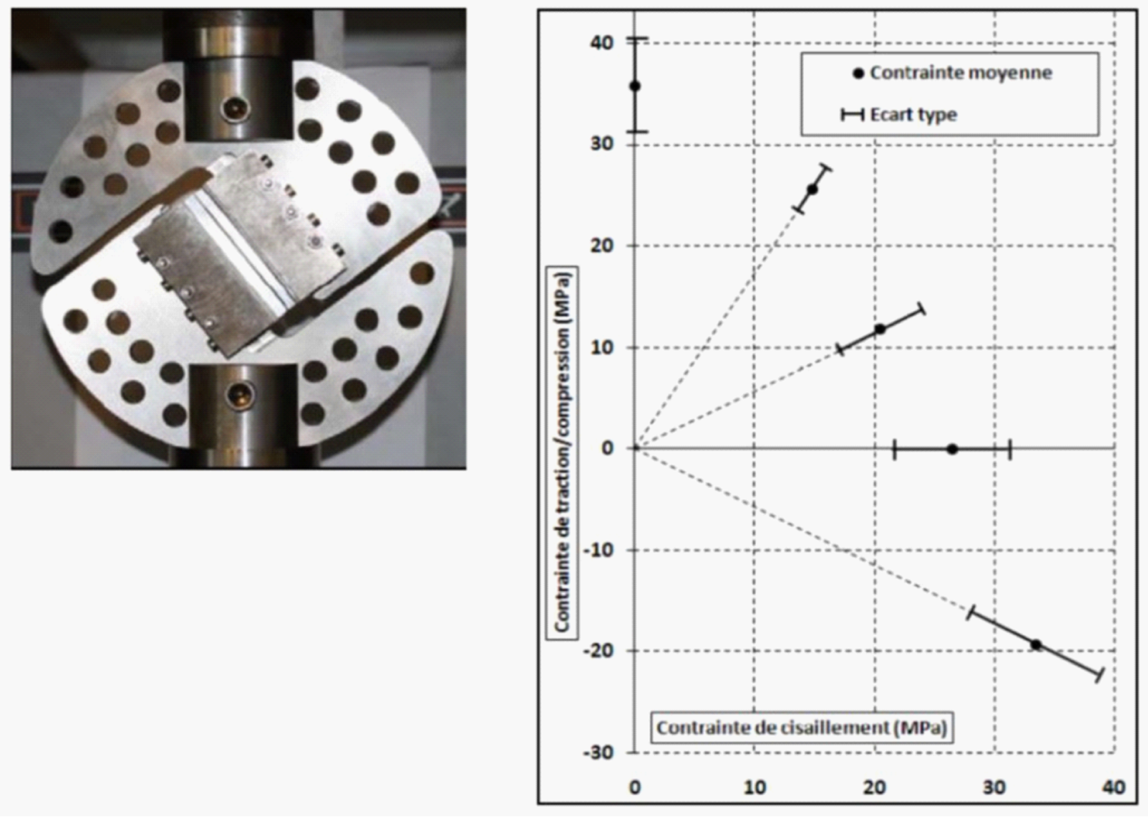 Figure: Average strength and standard deviation in tension, compression and shear for different angles of solicitation (0°, 30°, 60°, 90°, 120°) of EA9394 adhesive [ref Gregory Bresson, “Collage fiable pour l’espace : influence de la qualité des procédés et dimensionnement des assemblages”, thèse Université Bordeaux I, 2011]
Other standard test assemblies can exist with various loading modes:
Cleavage modes
Flatwise-tensile mode
Torsion
Fracture mechanics of adhesively bonded joints
Fracture mechanics test methods
Fracture mechanics test methods evaluate the quality of adhesives and design of bonded joints.
Fracture mechanics test methods evaluate presence of stress raisers in initiating failure.
To address the fracture mechanics of adhesively bonded joint please see 15.1.4.1 of ECSS-E-HB-32-21.
The list of relevant standards can be found in Table E-1.
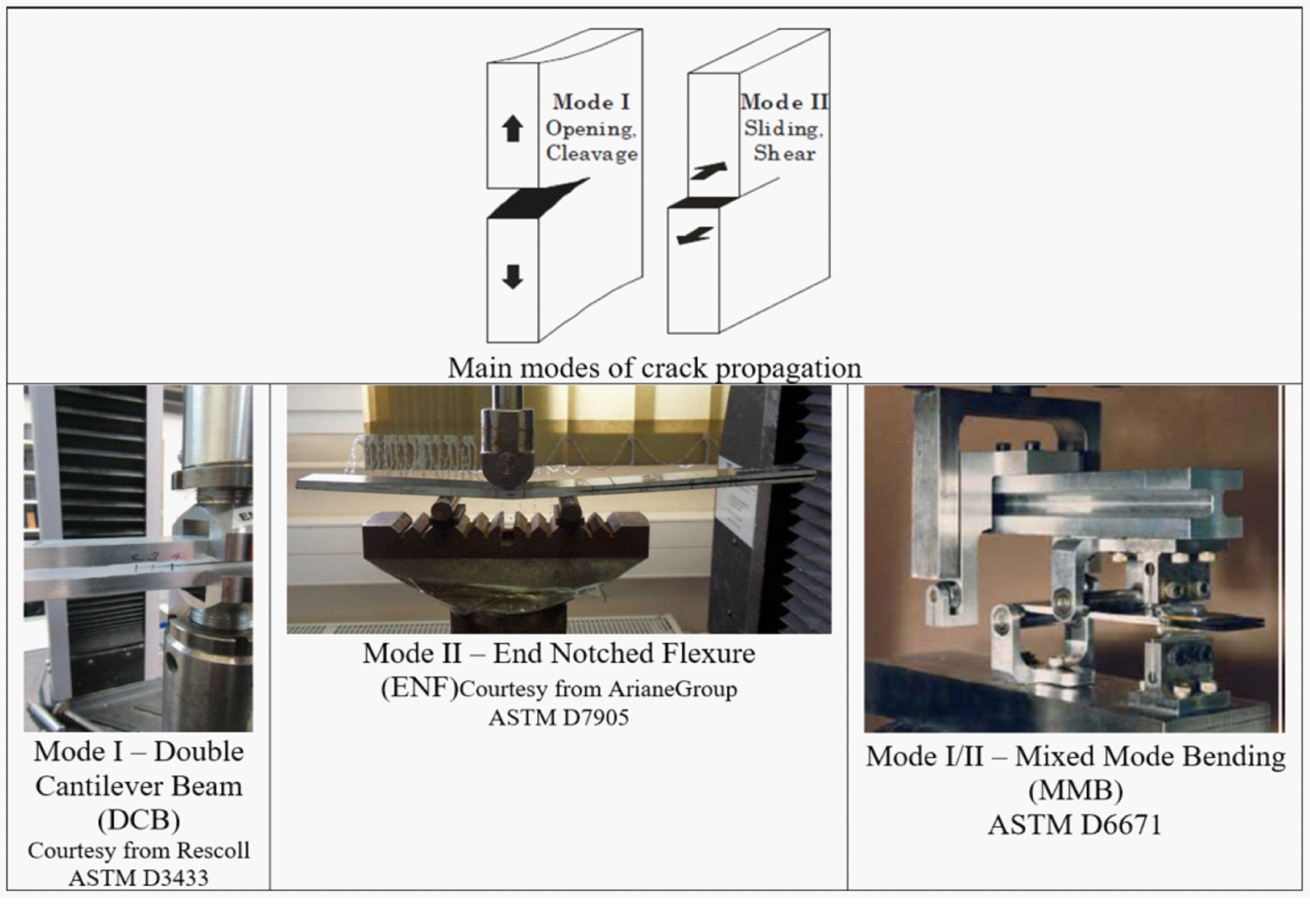 Figure: Examples of crack propagation modes and various test setups (courtesy ArianeGroup)
Adhesive characteristics to be verified by test (in bonded assemblies)
Some of the commonly applied test methods are summarised, by specimen type, in Table E-1. Test methods are often known by the name of the type of specimen used, rather than by their actual application. A detailed description of the test methods can be found in the related standards and in section 15 of ECSS-E-HB-32-21.
Table: Commonly applied test methods and related standards
|
Load mode
|
Test sample type
|
Key property
|
Standard number
|
|
Shear
|
|
|
|
|
Shear by tension
|
Single-Lap
|
Tensile Lap Shear strength
|
ASTM D1002-10
|
|
EN 1465:2009
| |||
|
ASTM D2295-96(2016)
| |||
|
ASTM D3163-01(2014)
| |||
|
ASTM D5868-01(2014)
| |||
|
ASTM D3165-07(2014)
| |||
|
ISO 4587:2003
| |||
|
BS 5350-C5:2002
| |||
|
EN 2243-1:2005
| |||
|
Single-Lap-thick adherends
|
Tensile Lap Shear strength & modulus
|
ISO 11003-2:2001
| |
|
EN 14869-2:2011
| |||
|
ASTM D3983-98(2011)
| |||
|
EN 2243-6:2005
| |||
|
ASTM D4501-01(2014)
| |||
|
ASTM D5656-10(2017)
| |||
|
Double-lap
|
Shear strength
|
ASTM D3528-96(2016)
| |
|
Shear by compression
|
Pin-and-collar
|
Cylinder in cylinder compression shear strength
|
EN 15337:2007
|
|
ASTM D4562-01(2013)
| |||
|
Shear in torsion
|
Butt‐bonded hollow cylinders
|
Torsion shear strength & modulus
|
ISO 11003-1:2001
|
|
BS EN 14869-1:2011
| |||
|
Torsion butt joint
|
Torsional fatigue
|
Test described in: Prakash, V. et al., 1995
| |
|
Torsional shear test sample
|
Torque strength & modulus
|
DIN 54455:2016-09
| |
|
Torque strength and locking effect
|
ISO 10964:1993, EN 15865:2009, ISO 10964:1993
| ||
|
Tensile
|
|
|
|
|
Tensile
|
Tensile butt joint
|
Tensile strength
|
ASTM D897-08(2016)
|
|
ASTM D2095-96(2015)
| |||
|
Tensile strength and modulus
|
EN 15870 (2009)
| ||
|
Cleavage
|
|
|
|
|
Cleavage
|
Wedge (cleavage)
|
Fracture energy, ageing proof, adhesion
|
DIN 65448 (1988-01)
|
|
Compact tension
|
Cleavage strength
|
ASTM D1062-08(2015)
| |
|
BS 5350-C1:1986
| |||
|
DCB - Flat, and DCB contoured
|
Fracture strength in cleavage, G1c and G1a
|
ASTM D3433-99(2012)
| |
|
Bending
|
End-notched, bending laminated beams
|
Interlaminar fracture toughness
|
ASTM D7905 / D7905M - 19e1, ASTM D6671 / D6671M - 19
|
|
Peel
|
|
|
|
|
Peel in roller
|
Thin to thick adherend plate
|
Peel strength
|
ASTM D3167-10(2017)
|
|
EN 1464:2010
| |||
|
EN 2243-2: 2005
| |||
|
ISO 4578:1997
| |||
|
Peel, 90°
|
Flexible-bonded-to-rigid
|
Peel strength
|
EN 28510-1:2014
|
|
Peel, 90° and 180°
|
T-peel
|
ISO 8510-2:2006
| |
|
Peel, 180°
|
ISO 11339:1993
| ||
|
ASTM D1876-08(2015)e1
| |||
|
Peel (by hand)
|
Bead peel test
|
Qualitative test of adhesion
|
DIN 54457:2014-09
|
|
Bonded sandwich constructions
|
|
|
|
|
Peel & Cleavage mix, 180deg
|
Laminated assembly, sandwich
|
Peel strength (average peel torque)
|
ASTM D1781-98(2012)
|
|
EN 2243-3:2005
| |||
|
Tensile
|
Flat-wise tensile, laminated assembly, sandwich
|
Flatwise tensile strengths
|
ASTM C297 / C297M-16
|
|
EN 2243-4:2005
| |||
|
Compression
|
Edgewise compression tests
|
Edgewise compressive strength
|
ASTM C364 / C364M-16
|
|
Bending
|
Long beam flexural
|
sandwich flexural stiffness, the core shear strength, and shear modulus
|
ASTM D7249 / D7249M-16e1
|
|
Tapes
|
|
|
|
|
Peel, 90 and 180deg
|
PSA tapes, flexible thin foils, various configurations
|
Peel strength
|
ASTM D3330 / D3330M-04(2010)
|
|
Peel, 180deg
|
PSA tapes, flexible thin foils, various configurations
|
Peel strength
|
ASTM D903-98(2017)
|
|
Peel, 90 and 180deg
|
PSA tape, 180deg (its own adhesion) and 90deg to stainless steel panel
|
Peel strength
|
EN 1939: 2003
|
|
Shear by tension
|
PSA tape, Various configurations
|
Tape shear adhesion
|
ASTM D3654 / D3654M-06(2011)
|
|
Shear by tension
|
PSA tape, Various configurations
|
Tape shear adhesion
|
ISO 29863:2007
|
|
Static and dynamic, long-term stability
|
|
|
|
|
Fatigue
|
|
|
|
|
Shear by tension/compression (cyclic)
|
Single lap shear
|
Fatigue strength
|
ASTM D3166-99(2012)
|
|
ISO 9664:1993
| |||
|
EN ISO 9664:1995-08
| |||
|
Creep
|
|
|
|
|
Shear by tension
|
Single lap shear
|
Creep strength in single lap shear
|
ASTM D2294-96(2016)
|
|
Creep, time to rupture
|
EN 15336:2007
| ||
|
Impact resistance
|
|
|
|
|
Shear in impact hammer
|
Shear impact test
|
Shear impact strength
|
ISO 9653:1998
|
|
ASTM D950-03(2011)
| |||
ANNEX(informative)Ageing effects on adhesively bonded joints
Introduction
Moisture absorption combined with temperature and mechanical loads is one of the main contributors of adhesive performance reduction. It is important to highlight that water is often an active factor in the ageing of bulk materials but also a powerful factor to reveal defects at the interface of the bond line between the adhesive and the adherend.
Ageing of adhesively bonded joints
Natural ageing
The ageing process can be defined as a gradual irreversible change in structure and function of a material that occur as a result of the passage of time in given environmental conditions.
Natural ageing is related to changes that take place in real-life ambient conditions. For example environment at the launch site or in controlled environment (indoor).
For both examples of exposure conditions a significant period of time is typically needed to achieve a noticeable degradation of adhesively bonded joints.
Accelerated ageing
To evaluate the resistance of joints against humid conditions, accelerated hot-wet tests are often employed for the process quality screening purposes.
Unfortunately, there is no exact analytical model that can accurately estimate the life degradation of complex adhesively bonded assemblies or systems. The following text further explains the complexity of the modelling of water diffusion trough polymers, its action in the bulk and life time prediction philosophy.
For critical adhesive bonds solicited for long-term service, it is recommended to determine the moisture diffusion kinetics which gives a better estimation of the moisture absorption into the joint.
Materials that allow moisture absorption through Fickian diffusion are characterized by two key properties:
Diffusion coefficient of the penetrant and
Equilibrium concentration of penetrant (water molecules) in absorber (polymer)
Fick’s law
The Fick’s law (
Equation 1) where J is the flux which gives the quantity of penetrant diffusing across unit area of medium per unit time and has units of mol.cm-2.s-1, D the diffusion coefficient, c the concentration, x the distance, and ∂c/∂x is called the gradient of the concentration along the axis [Karimi, M. 2011]. This relation is only applicable for steady state (equilibrium conditions) and assumes an infinite supply of penetrant diffusing into an infinite joint.
Equation 1
This equation is only for one material. If there are multiple materials (adhesive between two adherends), the thermodynamic variable to use is the activity of water in the medium. This thermodynamic formulation is explained in [Chen, L. 2017]. As the activity of water in air is equal to RH (perfect gas mixture, Henry’s law), we can note the activity of water (dimensionless parameter) in a medium which is in equilibrium with air with RH moisture. The material characteristic water concentration at equilibrium Csat (kg/m3) in a medium is a (non-linear) function of .
Therefore flux J is governed by
Equation 2 written in one dimension.
Deff is the effective diffusivity (m2/s) obtained experimentally.
Equation 2
where:
Note: This equation has been written by [Chen, L. 2017] with Diffusivity D (m2/s) and generalized solubility parameter K (kg/m3) which is a function of temperature and water activity.
In fact these parameters are linked with Equation 3 [Chen, L. 2017].
Equation 3
where:
and
Second Fick’s law
Under unsteady state circumstance at which the penetrant accumulates in the certain element of the system, Fick’s second law describes the diffusion process as given by Equation 4 [Karimi, M. 2011].
Equation 4
Concentration change ∂c of penetrant at certain element of the system with respect to the time (t), for one-dimensional diffusion per distance (∂x). Diffusion coefficient is D.
In case of multiple material, the second Fick’s law is written with C’ and with Equation 5 [Chen, L. 2017].
Equation 5
C’ is discontinuous across materials (it is a material characteristic), is continuous and is equal to ambient air RH on boundaries. At equilibrium, is equal to ambient air RH everywhere.
For each material (Figure F-1) and Deff (Figure F-2) are determined for different temperatures and moistures. In general Deff depends mainly on temperature (Arrhenius law) and mainly on moisture level for polymers. Equation 5 corresponds to the case of non-dependence of C with temperature.
Figure F-1 illustrates the evolution of the moisture concentration at saturation with moisture . may be described by a polynomial formula with .
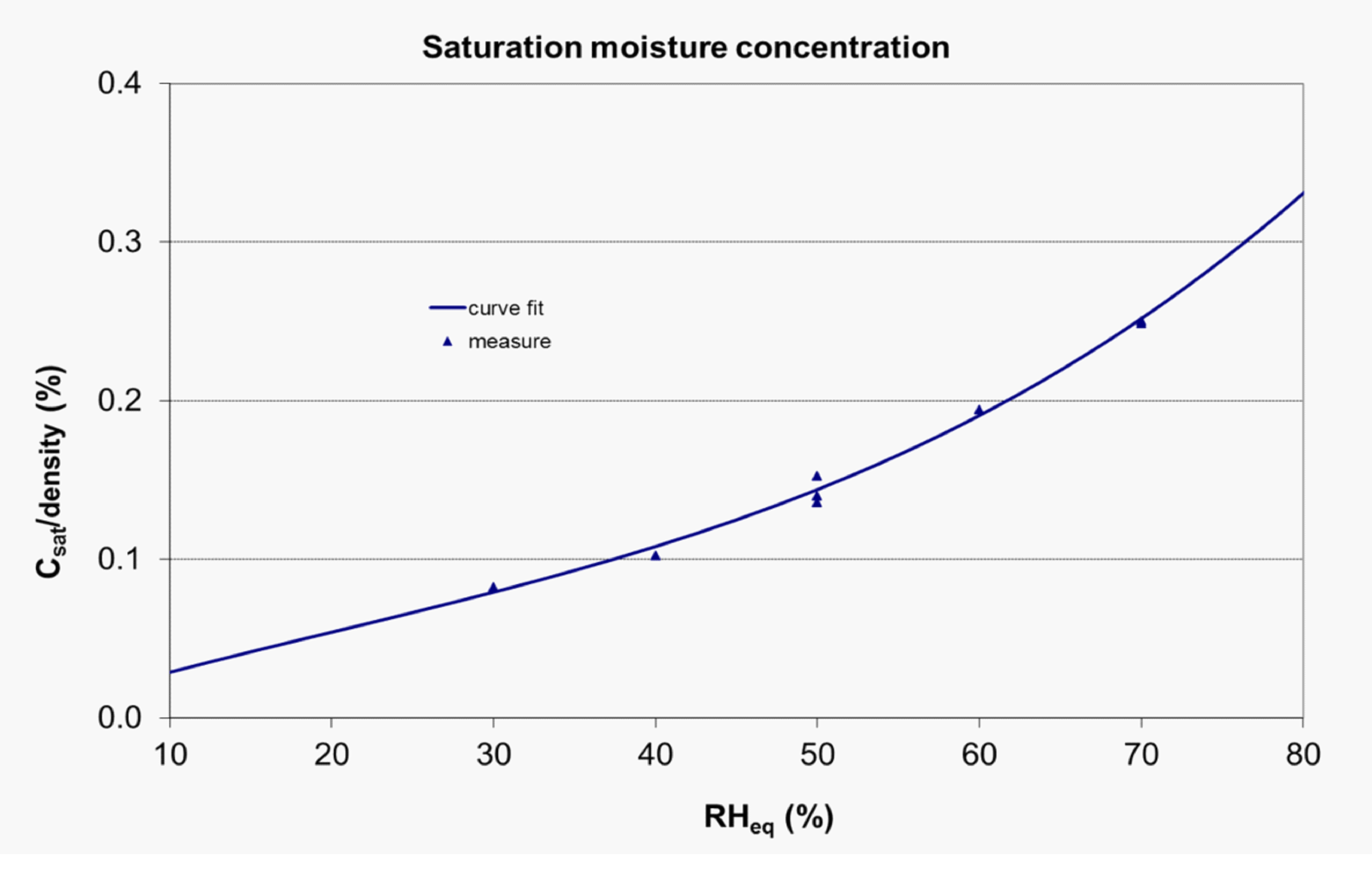 Figure: Example of non-linear evolution of Csat with RHeq for Glass fiber/epoxy resin [courtesy Ariane group]
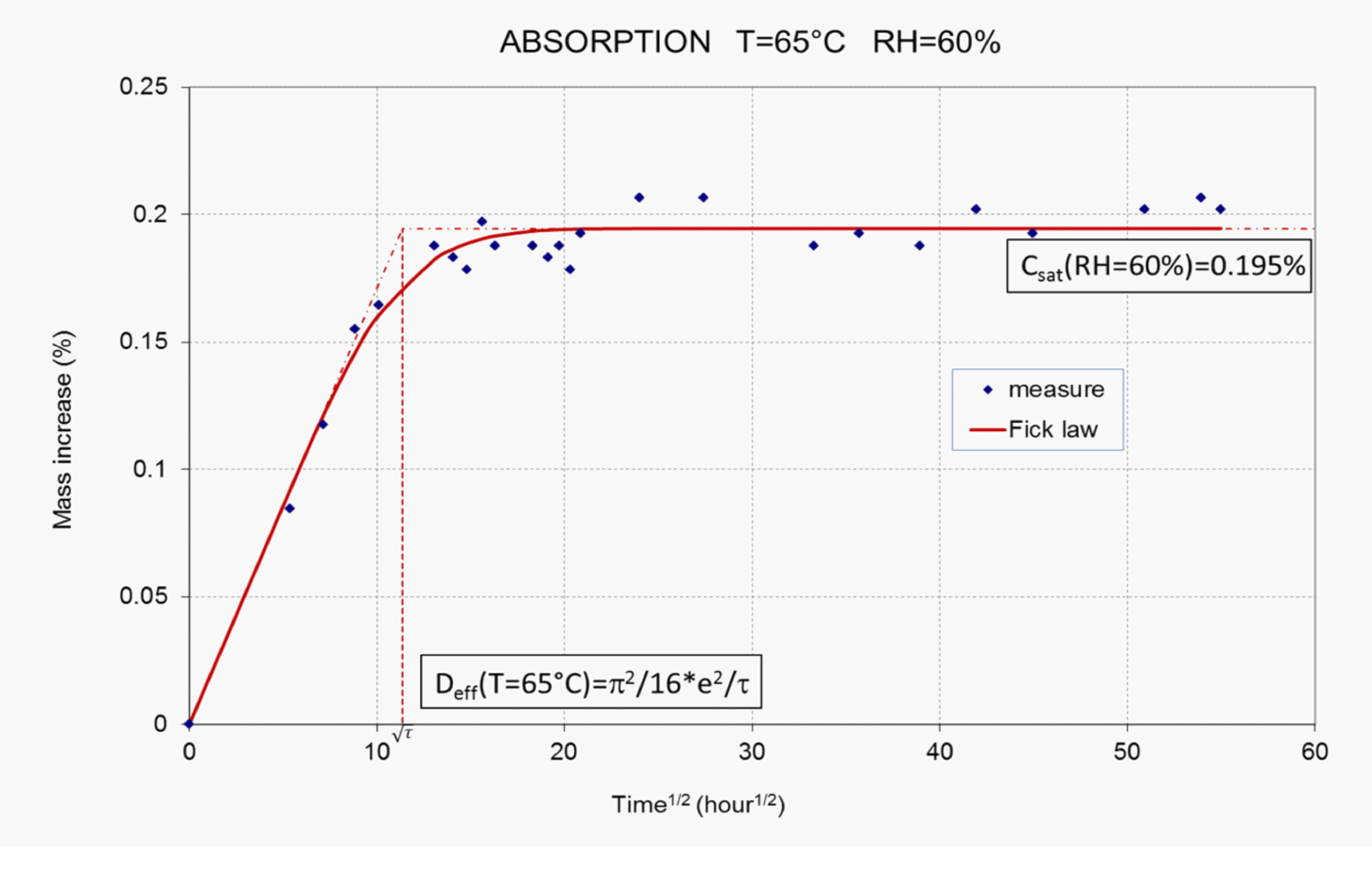 Figure: Example of determination Deff and Csat parameters from absorption curve; case of Glass fiber/epoxy resin with 65°C and RH=60% condition [property Ariane group], follows Fickian behaviour [courtesy ArianeGroup]
Water diffusion mechanisms and degradation models of adhesive joints
A review of the diffusion rates available in literature reveals that, in general, the diffusion rate along the interface of adhesive/adherend is faster than that of the bulk adhesive and it becomes more critical to the lifetime of the adhesive joints as the strength of the interface decreases [M.H. Shirangi and B. Michel].
Other authors [Vine Et. al] reported faster diffusion in three-layer sandwich specimens than predicted based on mass-uptake experiments performed on bulk diffusion specimens. They attributed this behaviour to the presence of micro-cavities in the adhesive layer [M.H. Shirangi and B. Michel].
Moisture diffusion in adhesives and in carbon-epoxy composites is generally considered to be Fickian [Gerben K et all 2000], although some studies have shown that under certain conditions, diffusion can be non-Fickian (see Figure F-3).
Non-Fickian behaviour can be the consequence of a relaxation process in polymer molecules and/or the result of an irreversible reaction between polymer and moisture such as formation of hydrogen bonds [M.H. Shirangi and B. Michel].
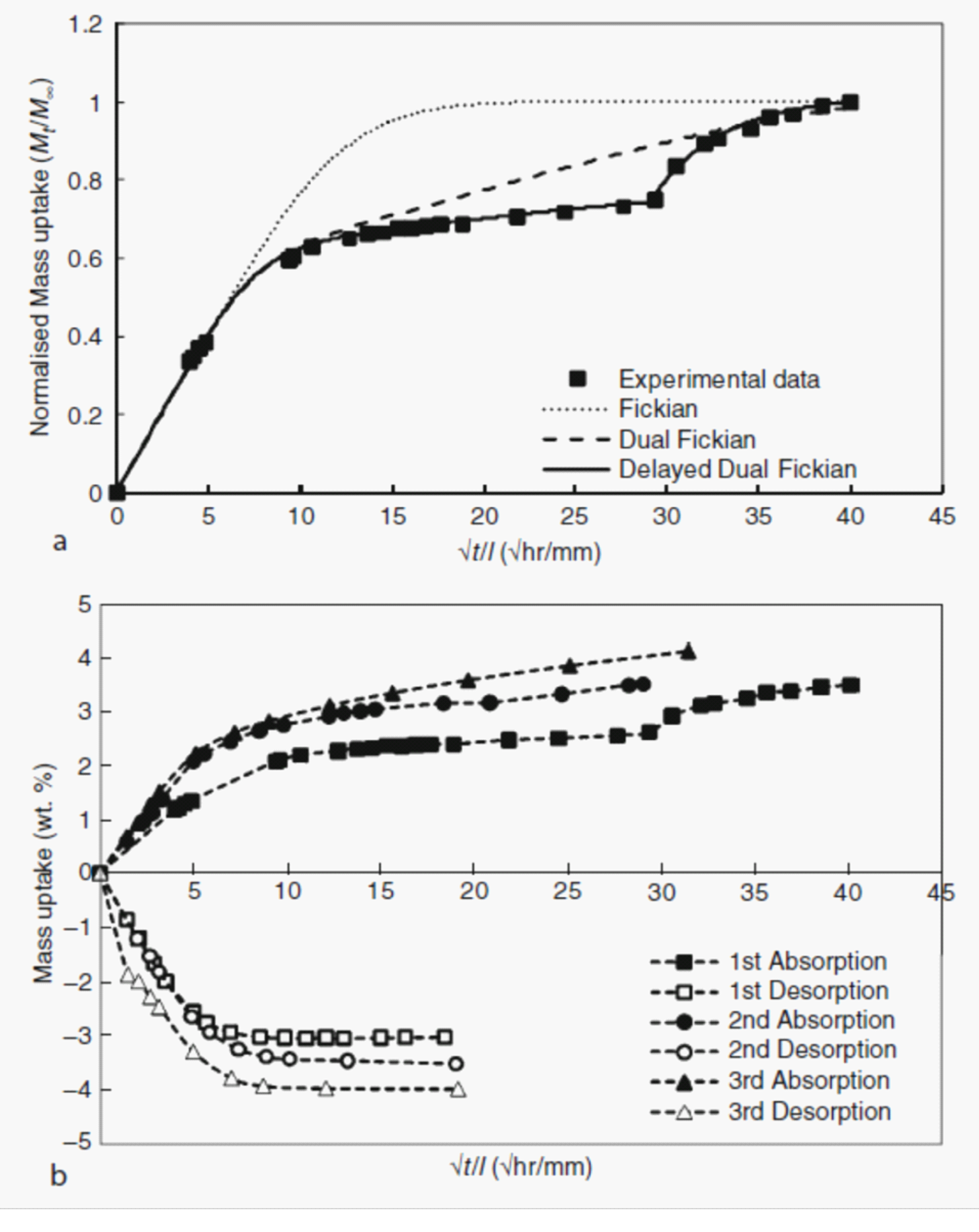 Figure: Illustration of a non-Fickian behaviour and evolution with sorption cycles of one component epoxy adhesive, (up) normalised mass uptake –various models, (down) moisture uptake and de-sorption [Mubashar, I. A. et al., 2009]
In some cases, a pseudo-equilibrium stage is reached in the moisture uptake, which is then followed by a secondary uptake process. It can also be seen that the uptake behaviour can be different in absorption and desorption and can change with number of sorption cycles (see Figure F-3).
The diffusion coefficient is one of the material properties which controls the rate of absorption of moisture in a material. The diffusion coefficient is highly dependent on temperature and weakly dependent on relative humidity. This is the reason why the Arrhenius temperature acceleration model can be used Equation 6).
The activation energy for diffusion (Ea in J/mol) can be different for each damage mechanism and material.
Equation 6
where:
D = diffusion coefficient (at infinite temperature; in m/s)
D0 = maximal diffusion coefficient (at infinite temperature; in m2/s)
Ea = activation energy for diffusion (J/mol)
T = temperature (K) and
R = gas constant 8,145 J/(mol·K).
Water concentration throughout the adhesive bond can be computed by solving Fick’s law knowing for each material, the water concentration at equilibrium and the diffusion coefficient. In the case of an adhesive joint with composite adherends, one can consider it is not necessary to know the coefficient of diffusion of the adhesive if the adhesive film is thin and the moisture diffusion is significantly faster throughout the adherend thickness.
In practice the coefficients of the model are commonly measured by the gravimetric test method, which exposes a specimen to a controlled humid environment.
For each couple of relative humidity ( RH) and temperature (T) the following parameters of the Fick’s law are determined:
Water concentration at equilibrium (asymptotic value of the moisture content curve
Coefficient of diffusion (slope of the curve M/M∞ versus t0,5).
By plotting D(T) in log scale versus 1/T, the D0 and Ea is determined.
The “through-the-thickness” moisture diffusion coefficient can be determined for single-phase material by assuming Fickian diffusion behaviour with constant moisture absorption properties through the thickness of the test specimen [ISO 62:2008] or for more complex matrix [ASTM D5229 / D5229M – 14 and MIL-HDBK-17B 1988 respectively].
Other techniques for determination of diffusion coefficient in polymeric materials can be found in literature (M.H. Shirangi and B. Michel, 2010, Hallberg, Ö. and Peck, D. S. 1991, Karimi, M. 2011 or Vine, K et al. 2001 and many others).
The robustness of the model is based on a test campaign covering different couples RH, T. It is recommended to perform for each material, 7 couples of conditions (RH,T) applied for each a minimum of 3 samples. A long period of ageing (more than one year or ambient conditioning) is needed to validate the model. Absorption and desorption tests are also needed to better identify the parameters of the model and long re-conditioning can be necessary to reach de-sorption equilibrium.
The determination of the knock-down factor of adhesion performance after accelerated ageing can be done experimentally with a minimum of 5 test samples for each point of measure.
A model developed to predict the life of semiconductors (corrosion phenomena) encapsulated in epoxy packaging has been proposed by Hallberg, Ö. and Peck, D. S. 1991.
Various moisture acceleration models exist, but they all need to be validated by data from natural ageing of representative samples (geometry).
For example, the data from work of M. Chevalier on accelerated models two component epoxy on aluminium adherends [M. Chevalier, 2008], see Figure F-4, show that the real life degradation after exposure to nominal cleanroom condition (22+-3degC, 55%RH+-10%) degraded by 16% after about 3,5 years. Based on real life aging data, the accelerated model obtained from the study has been validated only for accelerated moisture exposure at the temperature below the Tg.
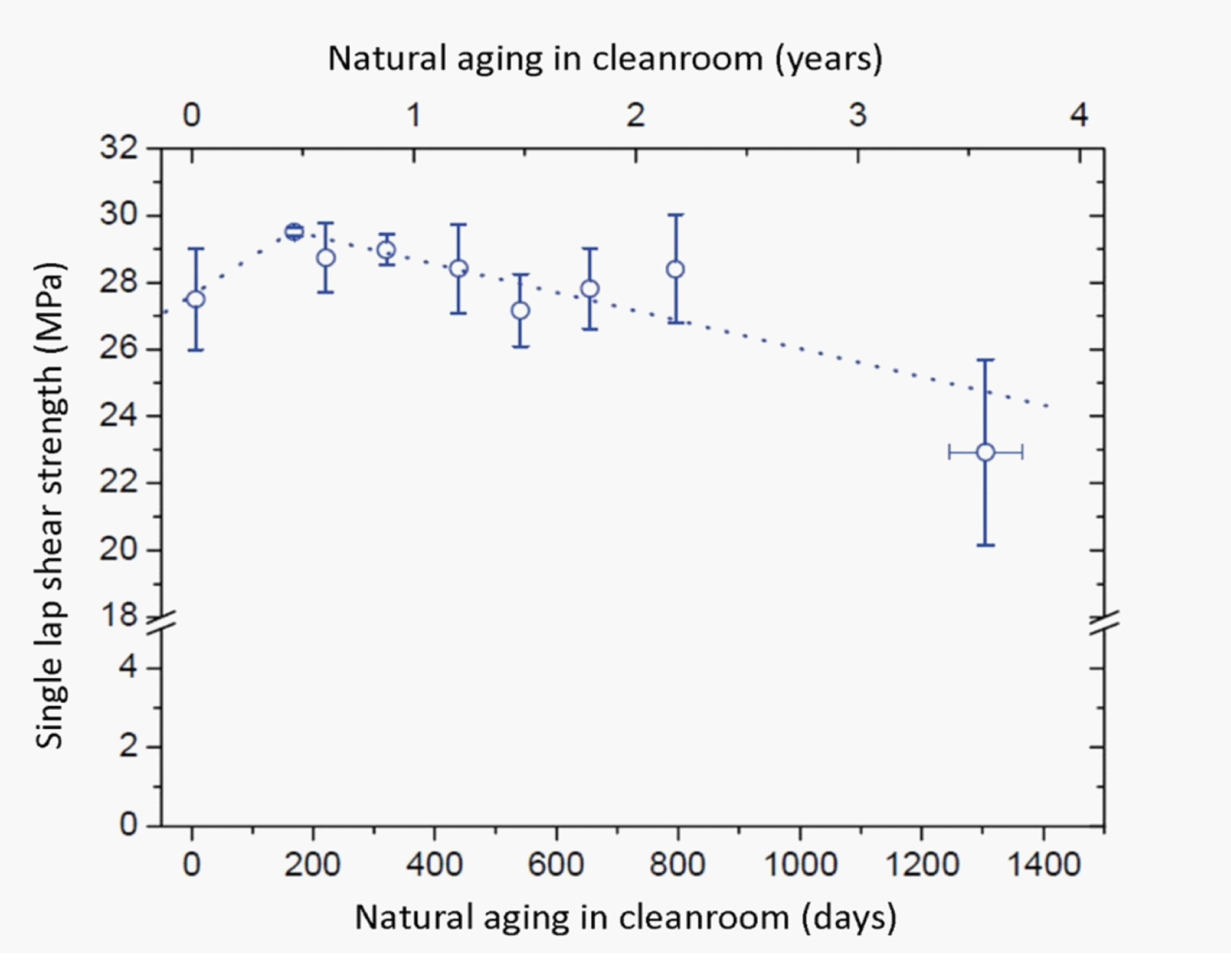 Figure: The effect of ambient exposure in a controlled environment on single lap shear strength of two component epoxy resin on aluminium as a function of time [M. Chevalier, 2008]
The influence of natural aging on fracture mode is important aspect. The following Figure F-5 shows the evolution of portion of cohesive fracture as function of storage time.
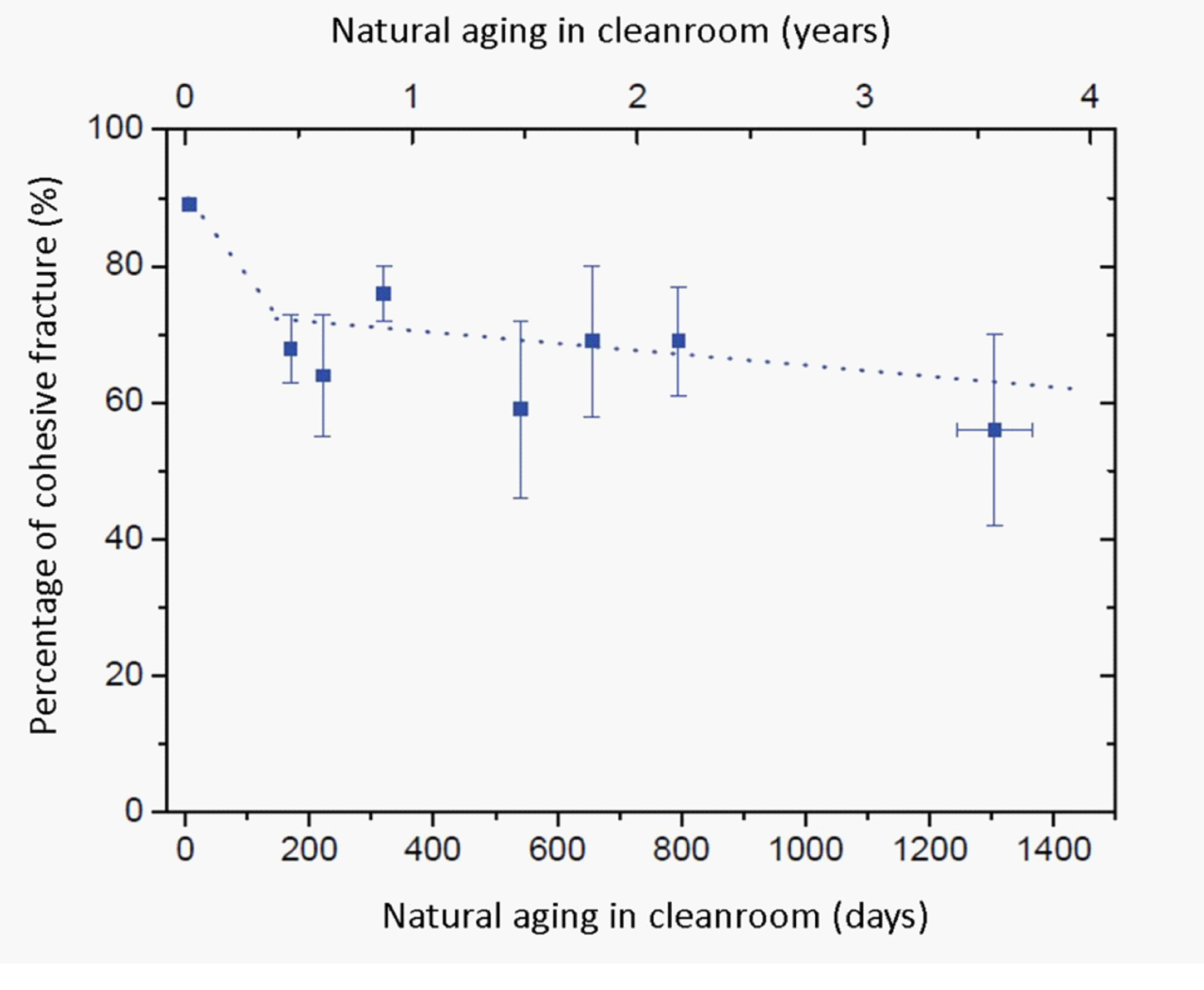 Figure: The effect of ambient exposure in a controlled environment on single lap shear fracture mode as a function of time [M. Chevalier, 2008]
Similar conclusion on natural aging exposure was observed by IFAM Fraunhofer in study for ESA [IFAM Fraunhofer, 2017], see Figure F-6, where two-component epoxy used for bonding of Titanium alloy to CFRP adherend experienced degradation of about 18% after 3.3 years stored in controlled laboratory room (22+-3degC, 55%RH+-10%).
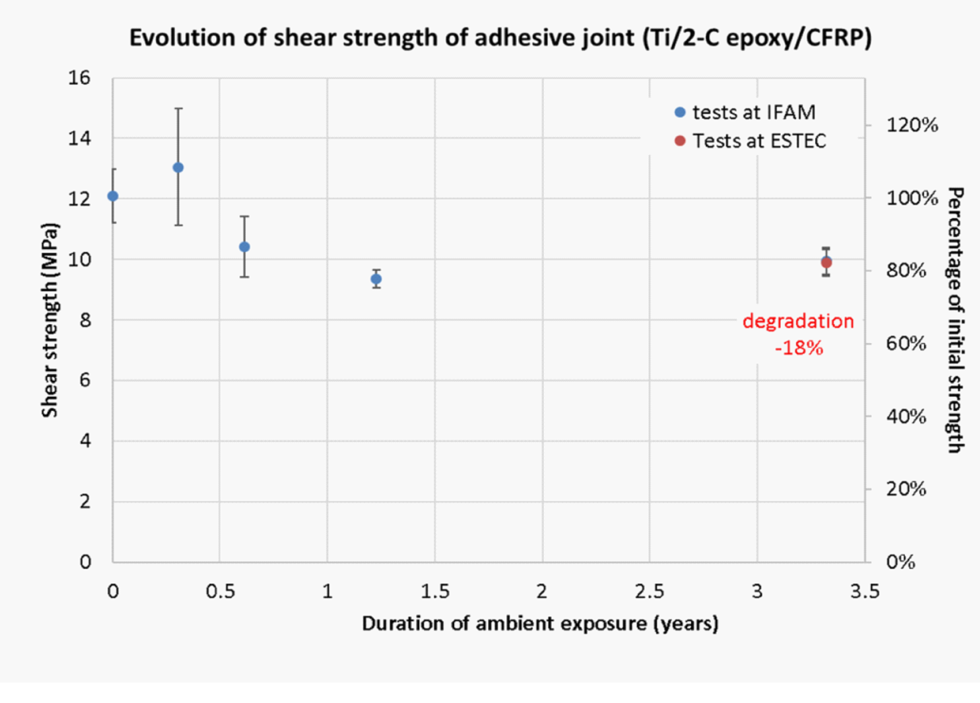 Figure: Evolution of single lap shear strength as a function of exposure duration in an ambient controlled environment [IFAM Fraunhofer, 2017]
Suitable definition of the moisture sensitivity is problematic. One of the proposed approaches can be found in MIL-HDBK-17B, 1988 for composite materials
Summary
The variety in bulk properties of adhesive materials due to their differences in polymer nature (silicones, epoxies, polyurethanes, cyanoacrylates), state (Tg, glassy vs. rubbery), crystallinity, degree of cure, curing mechanism, porosity, fillers and additives content on one hand and significant differences in quality and nature of the adhesive-adherend interface on other hand, make derivation of mathematical models for life time predictions in humid environments very complex. In practice it means that to determine the knock-down factors for adhesively bonded assemblies it is much easier to perform harsh and often very conservative engineering tests (for example EN 2243-5:2005) aiming at saturation and steady state conditions with respect to absorbed water content in the exposed assembly.
In case of temperature humidity accelerated tests for ambient life time predictions it is important that adhesive material is not passing through its glass transition temperature (Tg) during the acceleration ageing test cycle.
Examples of hot-wet exposure conditions to be used in verification sequence for spacecraft and launchers
Satellites, in-orbit units, probes
The aim is not to simulate the equivalent life time degradation caused by atmospheric moisture but mainly to verify the sensitivity of the adhesive joint to atmospheric moisture in general.
For the cases when the flight hardware is exposed only to relative humidity equivalent to clean room controlled environment, the following conditions can be used for hot-wet exposure:
Relative humidity: 70 % RH
Temperature : 50 °C
Duration : 7 days
- 1 For adhesives with a Tg between RT and 50°C, exposure temperature is not beyond 50°C.
- 2 Close to Tg typical adhesive materials are rapidly changing their properties with temperature, therefore exposure to humidity at Tg can lead to highly scattered test results regardless of the quality of the bonding process.
- 3 Selected temperature for the hot wet exposure is not above the temperature range of the thermal cycling used in the verification sequence.
Right after hot wet exposure, the adhesive layer is over-saturated with moisture when compared with adhesive exposed to clean room conditions. Therefore a reconditioning period to eliminate problems with oversaturation is necessary after hot-wet exposure before continuing with the next step in the test sequence.
For example reconditioning in clean room environment is typically minimum three days or longer depending on geometrical aspects of the test item.
Dedicated samples for monitoring mass change can be helpful for the determination of reconditioning time.
Based on experiences of many previous space programmes following tables contain some critical and less critical adhesive bonding applications (Table F-1) example of sensitivity to atmospheric moisture (Table F-2) and matrix for applicability of hot-wet exposure (Table F-3).
The approach for spacecraft is different for launcher applications (see F.3.2), where the equilibrium with worst-case conditions (high temperature and high moisture) is desired, to assess the sensitivity to moisture, as the hardware can be exposed to severe outdoor environments.
Table: Example of the classification of adhesive bonding process in spacecraft and launcher applications based on its criticality
|
Criticality
|
Definition and examples
|
|
Highly critical
|
Any adhesive joint, failure of which can lead to loss of mission, loss of spacecraft or loss of crew.
|
|
Critical
|
Any adhesive joint, failure of which can lead to significant damage of the spacecraft or degradation of the mission or injury of crew members.
|
|
Not critical
|
Any adhesive joint, failure of which has no adverse effect on the spacecraft or on the mission and cannot cause injury of crew members.
|
Table: Examples of adhesive bonding applications and their sensitivity to on-ground humidity exposure (based on their failure occurrence)
|
Sensitivity
|
Definition and examples
|
|
Highly sensitive
|
Performance of the key property is reduced by more than 35% after exposure to moisture with respect to reference value
|
|
Sensitive
|
Performance of the key property is reduced significantly (between 35 % and 10 %) after exposure to moisture with respect to reference value.
|
|
Insensitive
|
Performance of the key property is not affected after exposure to moisture (less than 10 % reduction) with respect to reference value.
|
The sensitivity level of the assembly can be assessed by accelerated hot-wet screening test in frame of adhesive selection process (see recommendation 5.2g.2(d)).
Recommendations on hot-wet exposure in the verification sequence of spacecraft assembled and stored in controlled environment, at ambient temperature of (22 ± 3) °C and relative humidity of (55 ± 10) %, can be derived from Table F-3.
Table: Example table with assessment for implementation of hot-wet exposure into the verification sequence (step: simulation of on-ground exposure)
|
|
Sensitivity of the adhesive bond to moisture
| |||
|
Highly sensitive
|
Sensitive
|
Non-sensitive
| ||
|
Criticality of the bonding process application
|
Highly critical
|
Yes
|
Yes
|
Yes
|
|
Critical
|
Yes
|
Yes
|
No
| |
|
Non-critical
|
Yes
|
No
|
No
| |
|
NOTE: Yes: hot-wet exposure is recommended to be performed, No: hot-wet exposure need not to be performed
| ||||
The accelerated ageing of adhesively bonded assemblies for launcher applications
The purpose of this type of tests is to determine the resistance of structural adhesives and adhesively bonded joints against environmental influences. The aim is to quantify the reduction in the key property.
The destructive tests are typically focusing on reduction in the single lap shear strength, peel strength, shear strength/strain and reduction in shear modulus after the environmental exposure.
The exposed test items are typically followed by destructive testing performed after certain time since their exposure.
Examples of hot-wet exposure tests
Typical hot-wet exposure conditions for verification of key property are listed in the Table F-4. List of tests for specific applications, where exposure to the mechanical load in combination with moisture stress is needed, is in the Table F-5.
Table: Examples of standard conditions for hot-wet exposures
|
Standard test reference
|
Test
|
Test conditions
|
Output
| ||
|
T
|
Humidity
|
Duration
| |||
|
ECSS-E-ST-10-03
|
Testing
|
2-35
|
50-95
|
4 cycles
|
Sequential check for deterioration
|
|
EN 2243-5:2005
|
Aerospace series - Non-metallic materials - Structural adhesives - Test method - Part 5: Ageing tests
|
50-70
|
95-100
|
30-90
|
Reduction factor –key property
|
|
ISO 9142:2003
|
Adhesives -- Guide to the selection of standard laboratory ageing conditions for testing bonded joints, Annex C
|
70
|
90-100
|
42
|
Ageing ratios
|
|
ASTM D618-13
|
Standard Practice for Conditioning Plastics for Testing, Procedure C
|
35
|
90
|
4
|
n/a
|
|
ISO 291:2008
|
Plastics - Standard atmospheres for conditioning and testing
|
23 - 27
|
50-65
|
Thickness dependent
|
n/a
|
|
*ASTM D5229 / D5229M – 14
|
Standard Test Method for Moisture Absorption Properties and Equilibrium Conditioning of Polymer Matrix Composite Materials
|
25 below Tg
|
85-98
|
variable
|
Plot: mass vs. time, equilibrium moisture content, diffusivity
|
|
ASTM D1828 - 01(2013)
|
Atmospheric Exposure of Adhesive-Bonded Joints and Structures
|
natural atmospheric exposure
|
Visual, Qualitative changes
| ||
|
NOTE: * Applicable for CFRP-core-CFRP sandwich structures
| |||||
Table: Examples of standard durability tests (mechanical and humidity stress combined)
|
Standard test reference
|
Test
|
Test conditions
|
Output
| ||
|
T
|
Humidity
|
Duration
| |||
|
ASTM D2919 - 01(2014)
|
Standard Test Method for Determining Durability of Adhesive Joints Stressed in Shear by Tension Loading
|
23-50
|
15-100
|
Not defined
|
Time to failure of single lap
|
|
ASTM D2918 - 99(2012)
|
Standard Test Method for Durability Assessment of Adhesive Joints Stressed in Peel
|
23-50
|
15-100
|
Not defined
|
Time to failure of peel sample
|
|
ASTM D3762 - 03(2010)
|
Standard Test Method for Adhesive-Bonded Surface Durability of Aluminum (Wedge Test)
|
23-70
|
15-100
|
Up to 30
|
Crack extension, fracture mode
|
|
ISO 14615:1997
|
Adhesives - Durability of structural adhesive joints -- Exposure to humidity and temperature under load (T-peel and single lap)
|
42-48
|
90-100
|
Not defined
|
Time to failure, cycles to failure
|
ANNEX(informative)System for training and qualification of adhesive bonding personnel
EWF - The European Federation for Welding, Joining and Cutting, was created in 1992 by all the welding institutes of the European Union with the aim of updating and harmonizing training, education, qualification and certification in the field of joining technology. [Quintino L. et al.].
In terms of training of adhesive bonding personnel EWF has developed harmonized guidelines for the European Adhesive Engineer, the European Adhesive Specialist and the European Adhesive Bonder. [Quintino L. et al.]
The visualisation of Professional Qualification scheme is presented in the Figure G-1.
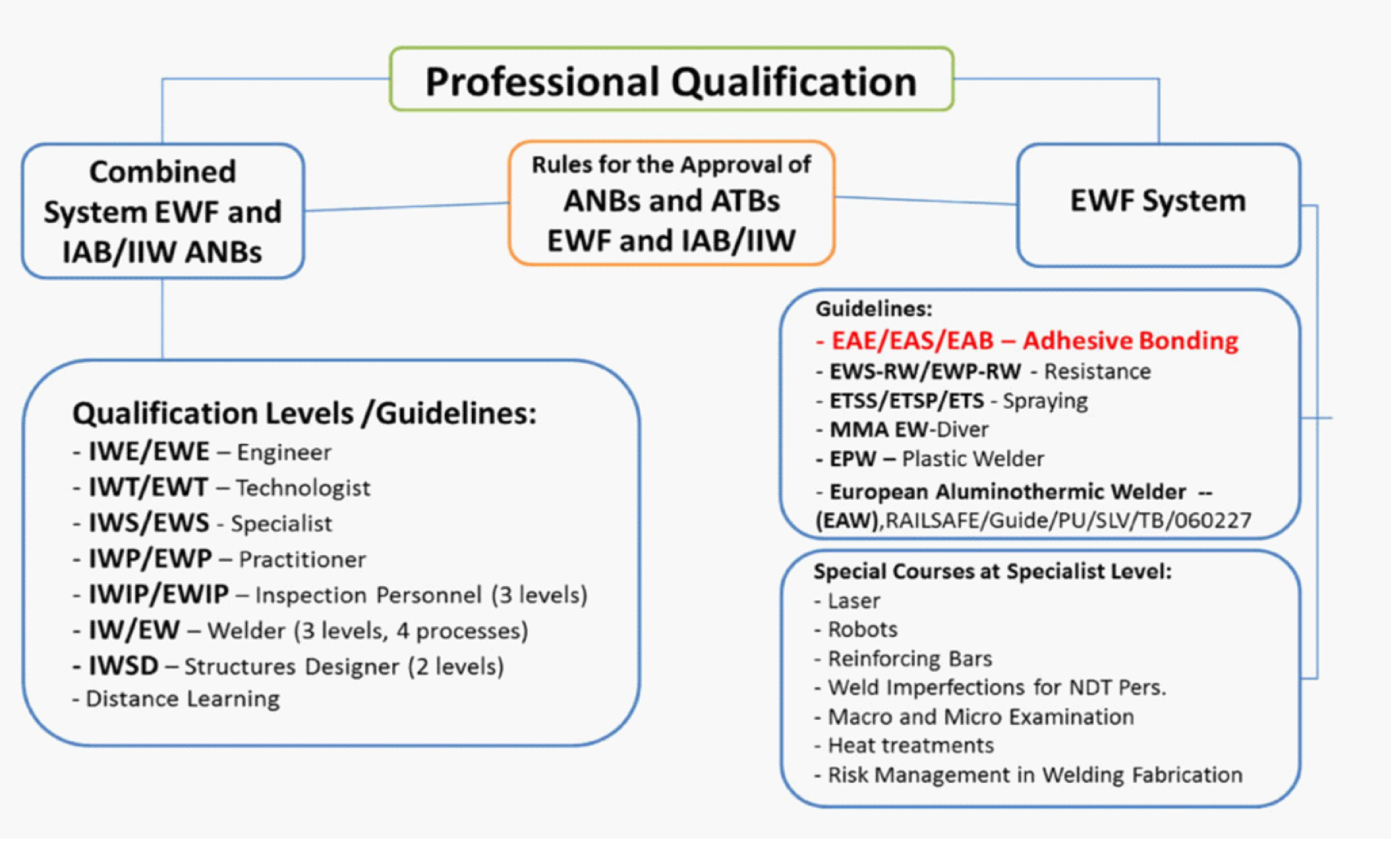 Figure: The International Training and Qualification system for Personnel [Quintino L. et al.]
Entities providing training for adhesive bonding are listed below. The training is structured in three levels:
European Adhesive Bonder (EAB), DVS® / EWF 3305 and EWF 515
European Adhesive Specialist (EAS), DVS® / EWF 3301 and EWF 516
European Adhesive Engineer (EAE), DVS® / EWF 3309 and EWF 517
Table: The list of entities eligible to provide training for adhesive bonding*
|
Country
|
School
|
Contact details
|
|
Austria
|
OFI GmbH
|
OFI Technologie & Innovation GmbH, Franz-Grill-Straße 5, Objekt 213, 1030 Wien
|
|
Belgium
|
TECHNIFUTUR
|
Technifutur® asbl, Liège Science Park, Rue Bois Saint-Jean 15-17, B-4102 – Seraing
|
|
Czech Republic
|
Centrum Lepení Brno
|
Centrum Lepení Brno, SVV Praha, s.r.o., Vídeňská 55, 639 00 Brno
|
|
France
|
Rescoll
|
Rescoll, 8 Allée Geoffroy Saint-Hilaire, 33600 Pessac
|
|
Germany
|
IFAM
|
Fraunhofer-Institut für Fertigungstechnik und Angewandte Materialforschung IFAM, Wiener Straße 12, 28359 Bremen
|
|
Germany
|
TC Kleben GmbH
|
TC-Kleben GmbH, Carlstraße 50, 52531 Übach-Palenberg
|
|
Germany
|
SKZ Halle
|
Frankfurter Str. 15-17, 97082 Würzburg
|
|
Italy
|
Istituto Italiano della Saldatura
|
Istituto Italiano della Saldatura, SEDE CENTRALE DI GENOVA, Lungobisagno Istria, 15A, 16141, Genova
|
|
Netherlands
|
Adhesive Bonding Center
|
Adhesive Bonding Center, Vaartweg 81E, 8243 PD Lelystad
|
|
Netherlands
|
Lijmacademie B.V. / IFAM
|
Lijmacademie B.V., Ericssonstraat 2, 5121 ML Rijen
|
|
Poland
|
Instytut Spawalnictwa
|
Instytut Spawalnictwa, ul. Błogosławionego Czesława 16-18, 44-100 GLIWICE
|
|
Spain
|
CESOL
|
CESOL, C/ Condado de Treviño, nº 2 – Local F31, 28033 Madrid
|
|
Spain
|
ITCS
|
ITCS - Ctra. de Molins de Rei a Sabadell, 79, Nau 8 bis NUEVO 08191 Rubí, Barcelona
|
|
NOTE: * The list in the table is not exhaustive and can change over time. Quoted entities often organise trainings also in other countries in collaboration with local universities or training institutes. For actual list of all Authorised Training Bodies (ATBs) consult your local Authorised National Body (ANB) or European Federation for Welding, Joining and Cutting (EWF).
| ||
Bibliography
|
ECSS-S-ST-00
|
ECSS system – Description, implementation and general requirements
|
|
ECSS-E-HB-32-21
|
Space engineering – Adhesive bonding handbook
|
|
ECSS-E-ST-10-02
|
Space engineering – Verification
|
|
ECSS-Q-ST-70-01
|
Space product assurance - Cleanliness and contamination control
|
|
ECSS-Q-ST-70-04
|
Space product assurance – Thermal testing for the evaluation of space materials, processes, mechanical parts and assemblies
|
|
ECSS-Q-ST-70-06
|
Space product assurance – Particle and UV radiation testing for space materials
|
|
ECSS-Q-TM-70-52
|
Kinetic outgassing of materials for space
|
|
ASTM D1002-10
|
Standard Test Method for Apparent Shear Strength of Single-Lap-Joint Adhesively Bonded Metal Specimens by Tension Loading (Metal-to-Metal)
|
|
ASTM D1062-08(2015)
|
Standard Test Method for Cleavage Strength of Metal-to-Metal Adhesive Bonds
|
|
ASTM D1193-06(2011)
|
Standard Specification for Reagent Water
|
|
ASTM D1746-15
|
Standard Test Method for Transparency of Plastic Sheeting
|
|
ASTM D1781-98(2012)
|
Standard Test Method for Climbing Drum Peel for Adhesives
|
|
ASTM D1824-16
|
Standard Test Method for Apparent Viscosity of Plastisols and Organosols at Low Shear Rates
|
|
ASTM D1876-08(2015)e1
|
Standard Test Method for Peel Resistance of Adhesives (T-Peel Test)
|
|
ASTM D2095-96(2015)
|
Standard Test Method for Tensile Strength of Adhesives by Means of Bar and Rod Specimens
|
|
ASTM D2294-96(2016)
|
Creep Properties of Adhesives in Shear by Tension Loading (Metal-to-Metal)
|
|
ASTM D2295-96(2016)
|
"Standard Test Method for Strength Properties of Adhesives in Shear by Tension Loading at Elevated Temperatures (Metal-to-Metal)"
|
|
ASTM D257-14
|
Standard Test Methods for DC Resistance or Conductance of Insulating Materials
|
|
ASTM D2918-99(2012)
|
Standard Test Method for Durability Assessment of Adhesive Joints Stressed in Peel
|
|
ASTM D2919-01(2014)
|
Standard Test Method for Determining Durability of Adhesive Joints Stressed in Shear by Tension Loading
|
|
ASTM D3163-01(2014)
|
Standard Test Method for Determining Strength of Adhesively Bonded Rigid Plastic Lap-Shear Joints in Shear by Tension Loading
|
|
ASTM D3165-07(2014)
|
Standard Test Method for Strength Properties of Adhesives in Shear by Tension Loading of Single-Lap-Joint Laminated Assemblies
|
|
ASTM D3166-99(2012)
|
Standard Test Method for Fatigue Properties of Adhesives in Shear by Tension Loading (Metal/Metal)
|
|
ASTM D3167-10(2017)
|
Standard Test Method for Floating Roller Peel Resistance of Adhesives
|
|
ASTM D3330 / D3330M-04(2010)
|
Standard Test Method for Peel Adhesion of Pressure-Sensitive Tape, (several methods)
|
|
ASTM D3418-15
|
Standard Test Method for Transition Temperatures and Enthalpies of Fusion and Crystallization of Polymers by Differential Scanning Calorimetry
|
|
ASTM D3433-99(2012)
|
Standard Test Method for Fracture Strength in Cleavage of Adhesives in Bonded Metal Joints
|
|
ASTM D3528-96(2016)
|
Standard Test Method for Strength Properties of Double Lap Shear Adhesive Joints by Tension Loading
|
|
ASTM D3654 / D3654M-06(2011)
|
Standard Test Methods for Shear Adhesion of Pressure-Sensitive Tapes
|
|
ASTM D3762-03(2010)
|
Standard Test Method for Adhesive-Bonded Surface Durability of Aluminum (Wedge Test)
|
|
ASTM D4065-12
|
Standard Practice for Plastics: Dynamic Mechanical Properties: Determination and Report of Procedures
|
|
ASTM D4496-13
|
Standard Test Method for D-C Resistance or Conductance of Moderately Conductive Materials
|
|
ASTM D4501 - 01(2014)
|
Shear Strength of Adhesive Bonds Between Rigid Substrates by the Block-Shear Method
|
|
ASTM D4562-01(2013)
|
Standard Test Method for Shear Strength of Adhesives Using Pin-and-Collar Specimen
|
|
ASTM D5229 / D5229M-14
|
Standard Test Method for Moisture Absorption Properties and Equilibrium Conditioning of Polymer Matrix Composite Materials
|
|
ASTM D5656-10(2017)
|
Standard Test Method for Thick-Adherend Metal Lap-Shear Joints for Determination of the Stress-Strain Behavior of Adhesives in Shear by Tension Loading
|
|
ASTM D570-98(2010)e1
|
Standard Test Method for Water Absorption of Plastics
|
|
ASTM D5868-01(2014)
|
Standard Test Method for Lap Shear Adhesion for Fiber Reinforced Plastic (FRP) Bonding
|
|
ASTM D5930-17
|
Standard Test Method for Thermal Conductivity of Plastics by Means of a Transient Line-Source Technique
|
|
ASTM D618-13
|
Standard Practice for Conditioning Plastics for Testing, Procedure C
|
|
ASTM D638-14
|
Standard Test Method for Tensile Properties of Plastics
|
|
ASTM D6671 / D6671M - 19
|
Standard Test Method for Mixed Mode I-Mode II Interlaminar Fracture Toughness of Unidirectional Fiber Reinforced Polymer Matrix Composites
|
|
ASTM D695-15
|
Standard Test Method for Compressive Properties of Rigid Plastics
|
|
ASTM D696-16
|
Standard Test Method for Coefficient of Linear Thermal Expansion of Plastics Between −30°C and 30°C with a Vitreous Silica Dilatometer
|
|
ASTM D7249 / D7249M-16e1
|
Standard Test Method for Facing Properties of Sandwich Constructions by Long Beam Flexure
|
|
ASTM D7905 / D7905M - 19e1
|
Standard Test Method for Determination of the Mode II Interlaminar Fracture Toughness of Unidirectional Fiber-Reinforced Polymer Matrix Composites
|
|
ASTM D897-08(2016)
|
Standard Test Method for Tensile Properties of Adhesive Bonds
|
|
ASTM D950-03(2011)
|
Standard Test Method for Impact Strength of Adhesive Bonds
|
|
ASTM E1131-08(2014)
|
Standard Test Method for Compositional Analysis by Thermogravimetry
|
|
ASTM E143-13
|
Standard Test Method for Shear Modulus at Room Temperature
|
|
ASTM E2113-04
|
Standard Test Method for Length Change Calibration of Thermomechanical Analyzers
|
|
ASTM E595-15
|
Standard Test Method for Total Mass Loss and Collected Volatile Condensable Materials from Outgassing in a Vacuum Environment
|
|
ASTM E831-03
|
Standard Test Method for Linear Thermal Expansion of Solid Materials by Thermomechanical Analysis
|
|
BS 5350-C1:1986
|
Methods of test for adhesives. Adhesively bonded joints: mechanical tests. Determination of cleavage strength of adhesive bonds
|
|
DIN 54455:2016-09
|
Testing of adhesives for metals and of bonded metal joints - Torsional shear test
|
|
DIN 54457:2014-09
|
Structural adhesives - Testing of adhesively bonded joints - Bead peel test
|
|
DIN 65448:1988-01
|
Aerospace; structural adhesives; wedge test
|
|
EN 12092:2001
|
Adhesives. Determination of viscosity
|
|
EN 1464:2010
|
Adhesives. Determination of peel resistance of adhesive bonds. Floating roller method
|
|
EN 1465:2009
|
Adhesives. Determination of tensile lap-shear strength of bonded assemblies
|
|
EN 14869-1:2011
|
Structural adhesives. Determination of shear behaviour of structural bonds. Torsion test method using butt-bonded hollow cylinders
|
|
EN 14869-2:2011
|
Structural adhesives - Determination of shear behaviour of structural bonds - Part 2: Thick adherends shear test (ISO 11003-2:2001, modified)
|
|
EN 15336:2007
|
Adhesives - Determination of the time to rupture of bonded joints under static load (ISO 15109:1998 modified)
|
|
EN 15337:2007
|
Adhesives - Determination of shear strength of anaerobic adhesives using pin-and-collar specimens (ISO 10123:1990 modified)
|
|
EN 15865:2009
|
Adhesives - Determination of torque strength of anaerobic adhesives on threaded fasteners (ISO 10964:1993 modified)
|
|
EN 15870:2009
|
Adhesives - Determination of tensile strength of butt joints (ISO 6922:1987 modified)
|
|
EN 1939: 2003
|
Self adhesive tapes - Determination of peel adhesion properties
|
|
EN 2243-2: 2005
|
Aerospace series - Non-metallic materials - Structural adhesives - Test method - Part 2: Peel metal-metal
|
|
EN 2243-3:2005
|
Aerospace series - Non-metallic materials - Structural adhesives - Test method - Part 3: Peeling test metal-honeycomb core
|
|
EN 2243-4:2005
|
Aerospace series - Non-metallic materials - Structural adhesives - Test method - Part 4: Metal-honeycomb core flatwise tensile test
|
|
EN 2243-5:2005
|
Aerospace series - Non-metallic materials - Structural adhesives - Test method - Part 5: Ageing tests
|
|
EN 2243-6:2005
|
Aerospace series - Non-metallic materials - Structural adhesives - Test method - Part 6: Determination of shear stress and shear strain
|
|
EN 28510-1:2014
|
Adhesives - Peel test for a flexible-bonded-to-rigid test specimen assembly - Part 1: 90° peel
|
|
EN ISO 9664:1995-08
|
Adhesives - Test methods for fatigue properties of structural adhesives in tensile shear (ISO 9664:1993);
|
|
ISO 10964:1993
|
Adhesives — Determination of torque strength of anaerobic adhesives on threaded fasteners
|
|
ISO 11003-1:2001
|
Adhesives ‐ Determination of shear behaviour of structural bonds. Part 1: Torsion test method using butt‐bonded hollow cylinders"
|
|
ISO 11339:1993
|
Adhesives -- 180 degree peel test for flexible-to-flexible bonded assemblies (T-peel test)
|
|
ISO 11357-1:2016
|
Plastics -- Differential scanning calorimetry (DSC) -- Part 1: General principles
|
|
ISO 11357-2:2013
|
Plastics -- Differential scanning calorimetry (DSC) -- Part 2: Determination of glass transition temperature and glass transition step height
|
|
ISO 11357-3:2018
|
Plastics -- Differential scanning calorimetry (DSC) -- Part 3: Determination of temperature and enthalpy of melting and crystallization
|
|
ISO 11357-4:2014
|
Plastics -- Differential scanning calorimetry (DSC) -- Part 4: Determination of specific heat capacity
|
|
ISO 11357-5:2013
|
Plastics -- Differential scanning calorimetry (DSC) -- Part 5: Determination of characteristic reaction-curve temperatures and times, enthalpy of reaction and degree of conversion
|
|
ISO 11358-1:2014
|
Plastics -- Thermogravimetry (TG) of polymers -- Part 1: General principles
|
|
ISO 11358-2:2014
|
Plastics -- Thermogravimetry (TG) of polymers -- Part 2: Determination of activation energy
|
|
ISO 11359-1:2014
|
Plastics -- Thermomechanical analysis (TMA) -- Part 1: General principles
|
|
ISO 11359-2:1999
|
Plastics -- Thermomechanical analysis (TMA) -- Part 2: Determination of coefficient of linear thermal expansion and glass transition temperature
|
|
ISO 11359-3:2002
|
Plastics -- Thermomechanical analysis (TMA) -- Part 3: Determination of penetration temperature
|
|
ISO 11443:2014
|
Plastics -- Determination of the fluidity of plastics using capillary and slit-die rheometers
|
|
ISO 1183-1:2019
|
Plastics — Methods for determining the density of non-cellular plastics — Part 1: Immersion method, liquid pycnometer method and titration method
|
|
ISO 14615:1997
|
Adhesives -- Durability of structural adhesive joints -- Exposure to humidity and temperature under load (T-peel and single lap)
|
|
ISO 15368:2001
|
Optics and optical instruments -- Measurement of reflectance of plane surfaces and transmittance of plane parallel elements
|
|
ISO 17212:2012
|
Structural Adhesives – Guidelines for the surface preparation of metals and plastics prior to adhesive bonding
|
|
ISO 22007-4:2017
|
Plastics -- Determination of thermal conductivity and thermal diffusivity -- Part 4: Laser flash method
|
|
ISO 2535:2001
|
Plastics — Unsaturated-polyester resins — Measurement of gel time at ambient temperature
|
|
ISO 2555:2018
|
Plastics — Resins in the liquid state or as emulsions or dispersions — Determination of apparent viscosity using a single cylinder type rotational viscometer method
|
|
ISO 291:2008
|
Plastics -- Standard atmospheres for conditioning and testing
|
|
ISO 29863:2007
|
Self adhesive tapes — Measurement of static shear adhesion
|
|
ISO 3521:1997
|
Plastics — Unsaturated polyester and epoxy resins — Determination of overall volume shrinkage
|
|
ISO 4578:1997
|
Adhesives -- Determination of peel resistance of high-strength adhesive bonds -- Floating-roller method
|
|
ISO 527-1:2019
|
Plastics -- Determination of tensile properties -- Part 1: General principles
|
|
ISO 527-2:2012,
|
Plastics - Determination of tensile properties - Part 2: Test conditions for moulding and extrusion plastics
|
|
ISO 62:2008
|
Plastics — Determination of water absorption
|
|
ISO 6721-1:2011
|
Plastics -- Determination of dynamic mechanical properties -- Part 1: General principles
|
|
ISO 6721-10:2015
|
Plastics -- Determination of dynamic mechanical properties -- Part 10: Complex shear viscosity using a parallel-plate oscillatory rheometer
|
|
ISO 8510-2:2006
|
Peel strength Adhesives -- Peel test for a flexible-bonded-to-rigid test specimen assembly -- Part1 90 degree peel, Part 2: 180 degree peel
|
|
ISO 9142:2003
|
Adhesives -- Guide to the selection of standard laboratory ageing conditions for testing bonded joints, Annex C
|
|
ISO 9653:1998
|
Adhesives -- Test method for shear impact strength of adhesive bonds
|
|
ISO 9664:1993
|
Adhesives -- Test methods for fatigue properties of structural adhesives in tensile shear
|
|
MIL-HDBK-17B, 1988
|
MILITARY HANDBOOK: POLYMER MATRIX COMPOSITES - VOLUME 1 - GUIDELINES (29 FEB 1988) [S/S BY MIL-HDBK-17/1]
|
|
Chen, L. 2017
|
L. Chen et al. / Microelectronics Reliability 75 (2017) 162–170, http://dx.doi.org/10.1016/j.microrel.2017.06.055
|
|
G. Bresson
|
“Collage fiable pour l’espace : influence de la qualité des procédés et dimensionnement des assemblages”, thèse Université Bordeaux I, 2011
|
|
Gerben K. van der Wei and Olaf C.G. Adan, 2000
|
Moisture transport and equilibrium in organic coatings, HERON, Vol. 45, No. 2 (2000) ISSN 0046-7316, January 2000,
|
|
Habenicht, G. 2009
|
Applied Adhesive Bonding: A Practical Guide for Flawless Results, ISBN: 978-3-527-32014-1,
|
|
Hallberg, Ö. and Peck, D. S., 1991
|
Hallberg, Ö. and Peck, D. S. (1991), Recent humidity accelerations, a base for testing standards. Qual. Reliab. Engng. Int., 7: 169–180. doi:10.1002/qre.4680070308
|
|
IFAM Fraunhofer, 2017
|
Development of a methodology to predict long-term degradation of adhesively bonded joints, Klapp and Baha II, WP-PB-baha- A314099-2-final-00, ESA study, Contract: 000112991/14/NL/PA, 2017
|
|
Karimi, M. 2011
|
Mohammad Karimi (2011). Diffusion in Polymer Solids and Solutions, Mass Transfer in Chemical Engineering Processes, Dr. Jozef Markoš (Ed.), ISBN: 978-953-307-619-5, InTech, Available from: http://www.intechopen.com/books/mass-transfer-in-chemical-engineering-processes/diffusion-in-polymersolids-and-solutions, 16.2.2018
|
|
M. Chevalier, 2008
|
Vieillissement Hygrothermique D'assemblages Structuraux Polyepoxy: Analyse De La Mobilite Moleculaire Par Spectroscopie Dielectrique Dynamique, PhD thesis, Délivré par l'Université Toulouse III, 2008
|
|
M.H. Shirangi and B. Michel, 2010
|
Mechanism of Moisture Diffusion, Hygroscopic Swelling, and Adhesion Degradation in Epoxy Moulding Compounds, X.J. Fan, E. Suhir (eds.), Moisture Sensitivity of Plastic Packages of IC Devices, 29, Micro- and Opto-Electronic Materials, Structures, and Systems, DOI 10.1007/978-1-4419-5719-1_2, C Springer Science+Business Media, LLC 2010
|
|
Mubashar, I. A. et al., 2009
|
A. Mubashar, I. A. Ashcroft, G. W. Critchlow & A. D. Crocombe, Modelling Cyclic Moisture Uptake in an Epoxy Adhesive A., The Journal of Adhesion Vol. 85, Iss. 10, 2009
|
|
Mubashar, I. A. et al., 2009
|
A. Mubashar, I.A. Ashcroft, G.W. Critchlow, A.D. Crocombe, Moisture absorption–desorption effects in adhesive joints, International Journal of Adhesion and Adhesives, Volume 29, Issue 8, 2009, Pages 751-760, ISSN 0143-7496, https://doi.org/10.1016/j.ijadhadh.2009.05.001. (http://www.sciencedirect.com/science/article/pii/S0143749609000499)
|
|
Prakash, V. et al., 1995
|
V. Prakash, C. M. Chen, A. Engelhard, and G. Powell “Torsional fatigue test for adhesive bonded butt joints,”, Journal of Testing and Evaluation, vol. 23, no. 3, pp. 228–230, 1995, ISSN 0090-3973
|
|
Quintino L. et al. 2008
|
Quintino L, Ferraz R, Fernandes I: International education qualification and certification systems in welding. Welding World 2008, 52: 1.
|
|
Vine, K et al. 2001
|
The Correlation of Non-Destructive Measurements and Toughness Changes in Adhesive Joints during Environmental Attack, K. Vine, P. Cawleyfhofer & A. J. Kinloch, The Journal of Adhesion Vol. 77, Iss. 2, 2001
|