
Space engineering
Structural design and verification of pressurized hardware
Foreword
This Standard is one of the series of ECSS Standards intended to be applied together for the management, engineering and product assurance in space projects and applications. ECSS is a cooperative effort of the European Space Agency, national space agencies and European industry associations for the purpose of developing and maintaining common standards. Requirements in this Standard are defined in terms of what shall be accomplished, rather than in terms of how to organize and perform the necessary work. This allows existing organizational structures and methods to be applied where they are effective, and for the structures and methods to evolve as necessary without rewriting the standards.
This Standard has been prepared by the ECSS-E-ST-32-02 Working Group, reviewed by the ECSS Executive Secretariat and approved by the ECSS Technical Authority.
Disclaimer
ECSS does not provide any warranty whatsoever, whether expressed, implied, or statutory, including, but not limited to, any warranty of merchantability or fitness for a particular purpose or any warranty that the contents of the item are error-free. In no respect shall ECSS incur any liability for any damages, including, but not limited to, direct, indirect, special, or consequential damages arising out of, resulting from, or in any way connected to the use of this Standard, whether or not based upon warranty, business agreement, tort, or otherwise; whether or not injury was sustained by persons or property or otherwise; and whether or not loss was sustained from, or arose out of, the results of, the item, or any services that may be provided by ECSS.
Published by: ESA Requirements and Standards Division
ESTEC, ,
2200 AG Noordwijk
The
Copyright: 2008 © by the European Space Agency for the members of ECSS
Change log
|
ECSS-E-ST-32-02A
|
Never issued
|
|
ECSS-E-ST-32-02B
|
Never issued
|
|
ECSS-E-ST-32-02C
|
First issue
|
|
ECSS-E-ST-32-02C Rev. 1
|
First issue revision 1.
|
Scope
This Standard defines the structural design verification of metallic and non-metallic pressurized hardware which includes pressure vessels, pressurized structures, pressure components (such as valves, pumps, lines, fittings, and hoses), and special pressurized equipment (e.g. batteries, heat pipes, cryostats, sealed containers, hazardous fluids container). External supports and structural interfaces of pressurized hardware are not covered by this standard. Solid propellant motor cases are not covered by this standard.
Objectives of the associated verification process are primarily to demonstrate the qualification of design and performance, as meeting all specified requirements, and to ensure that the flight hardware is free from workmanship defects and acceptable for flight.
This Standard applies to all space products and in particular to launch vehicles, transfer vehicles, re-entry vehicles, spacecraft, space station, landing probes and rovers, sounding rockets, payloads and instruments.
This standard may be tailored for the specific characteristics and constraints of a space project in conformance with ECSS-S-ST-00.
Normative references
The following normative documents contain provisions which, through reference in this text, constitute provisions of this ECSS Standard. For dated references, subsequent amendments to, or revision of any of these publications, do not apply. However, parties to agreements based on this ECSS Standard are encouraged to investigate the possibility of applying the more recent editions of the normative documents indicated below. For undated references, the latest edition of the publication referred to applies.
|
ECSS-S-ST-00-01
|
ECSS system – Glossary of terms
|
|
ECSS-E-ST-10-02
|
Space engineering – Verification
|
|
ECSS-E-ST-10-03
|
Space engineering – Testing
|
|
ECSS-E-ST-32
|
Space engineering – Structural general requirements
|
|
ECSS-E-ST-32-01
|
Space engineering – Fracture control
|
|
ECSS-E-ST-32-08
|
Space engineering – Materials
|
|
ECSS-E-ST-32-10
|
Space engineering – Reliability based mechanical factors of safety
|
|
ECSS-Q-ST-20
|
Space product assurance – Quality assurance
|
|
ECSS-Q-ST-70
|
Space product assurance – Materials, mechanical parts and processes
|
Terms, definitions, and abbreviated terms
Terms from other standards
For the purpose of this Standard, the terms and definitions from ECSS-S-ST-00-01, ECSS-E-ST-32, and ECSS-E-ST-32-01 apply.
Terms specific to the present standard
autofrettage
vessel sizing operation where pressure driven deflection is used to plastically yield the metal liner into the overlying composite in order to induce initial compressive stress states in the metal liner
Autofrettage is considered to be part of the manufacturing process and is conducted prior to acceptance test.
boss
zone of a pressure vessel or a pressurized structure ensuring functional interfaces (e.g. fluid connections and mechanical interfaces) of the hardware with the pressurized system
burst factor (jburst)
multiplying factor applied to the maximum design pressure (MDP), to obtain the design burst pressure
The burst factor corresponds to an ultimate factor of safety.
burst pressure
pressure level at which collapse, rupture or unstable fracture of the pressurized hardware occurs
composite over-wrap
layers of fibre-based composite material applied onto a liner, sustaining significant pressure and environmental loads
composite over-wrapped pressure vessel (COPV)
pressure vessel with a fibre-based composite structure fully or partially encapsulating a liner
For example:
- the liner can be metallic or not.
- the liner ensures the leak tightness of the vessel.
composite over-wrapped pressurized component (COPC)
pressurized component with a fibre-based composite system fully or partially encapsulating a liner
For example:
- the liner can be metallic or not.
- the liner ensures the leak tightness of the vessel.
composite over-wrapped pressurized structure (COPS)
pressurized structure with a fibre-based composite system fully or partially encapsulating a liner
For example:
- the liner can be metallic or not.
- the liner ensures the leak tightness of the vessel.
composite over-wrapped special pressurized equipment (COSPE)
special pressurized equipment with a fibre-based composite system fully or partially encapsulating a liner
For example:
- the liner can be metallic or not.
- the liner ensures the leak tightness of the vessel.
composite pressure vessel (CPV)
pressure vessel whose structural wall is fully composed with fibre based composite material
For example:
- the permeation barrier can be ensured by a coating on the internal or the external shape of the composite wall, or by the composite wall itself, or by both.
- low-pressure liquid hydrogen tank without liner.
composite pressurized structure (CPS)
pressurized structure whose structural wall is fully composed with fibre based composite material
For example:
- the permeation barrier can be ensured by a coating on the internal or external shape of the composite wall, or by the composite wall itself, or by both.
- low-pressure liquid hydrogen structural tank without liner.
critical flaw
specific flaw with a size such that unstable growth occurs under the specific operating load and environment
cryostat
vacuum-jacketed container designed to keep its contents at a low (cryogenic) temperature
Cryostat is also known as a Dewar, named after its inventor.
design burst pressure
differential pressure to be withstood by the pressurized hardware without burst in the applicable operating environment
The design burst pressure is equal to the product of the MDP and the burst factor.
differential pressure
internal pressure minus external pressure
external pressure
absolute pressure outside the pressurized hardware
fibre failure
rupture or kinking of a bundle of filaments
There are two fibre failure modes: under tension (fibre rupture) and under compression (kinking).
fitting
pressure component of a pressurized system utilized to connect lines, other pressure components or pressure vessels within the system
hazardous fluid container
pressurized container, compartment or housing that is individually sealed to contain a fluid, which can create a hazard if released
hydrogen embrittlement
mechanical and environmental process that results from the initial presence or absorption of excessive amounts of hydrogen in metals
Usually it occurs in combination with residual or applied tensile stresses.
impact damage
induced defect caused by an object strike on the pressurized hardware or pressurized hardware strike on an object
Delamination in the composite over-wrap of a COPV, dent in the metallic liner of a COPV.
inter-fibre failure
micro-cracking in the matrix of a composite material, or at the interface filament-matrix of a composite material
internal pressure
absolute pressure inside the pressurized hardware
leak-before-burst (LBB)
fracture mechanics design concept, showing that any potentially critical flaw grows through the wall of a pressurized system and cause pressure relieving leakage at MDP without burst (catastrophic failure)
liner
part of pressurized hardware serving as a mandrel during the manufacturing of the over-wrap and as fluid permeation barrier when in contact with the stored fluid
For example:
- when the liner is made of metallic material, it can carry significant pressure and environmental loads.
- when the liner is made of homogeneous non metallic material, it usually does not carry significant pressure and environmental loads.
line
tubular pressurized hardware of a pressurized system provided as means for transferring fluids between components of the system
Flex hoses are included.
maximum design pressure (MDP)
See ECSS-E-ST-32.
maximum expected operating pressure (MEOP)
See ECSS-E-ST-32.
mechanical damage
induced flaw in pressurized hardware item which is caused by surface abrasions, cuts or impacts
The pressurized hardware item can be a metallic, homogeneous non metallic or composite item.
metallic pressure vessel (MPV)
pressure vessel fully composed of metallic material
metallic pressurized structure (MPS)
pressurized structure fully composed of metallic material
metallic pressurized component (MPC)
pressurized component fully composed of metallic material
metallic special pressurized equipment (MSPE)
special pressurized equipment fully composed of metallic material
non-hazardous LBB failure mode
leak-before-burst (LBB) behaviour that does not result in a hazard
For example: LBB behaviour with a leak of liquid or gas that is not toxic, reactive or flammable.
pressure component (PC)
component in a pressurized system, other than a pressure vessel, pressurized structure, or special pressurized equipment that is designed largely by the internal pressure
For example:
- lines, fittings, gauges, valves, bellows, and hoses.
- batteries not meeting the pressure vessel definition.
pressure vessel (PV)
pressurized hardware designed primarily for the storage of pressurized fluid with an energy level greater than or equal to 19310 Joules, or with a pressure greater than or equal to 0,69 MPa, or which can create a hazard if released
E.g. the stored energy can be calculated by the formula for the reversible adiabatic (isentropic) expansion of the confined gas:
 where:
E is the stored energy;
P1 is the internal pressure;
P2 is the external pressure;
V is the pressurized volume;
is the ratio of specific heat of the gas.
pressurized hardware (PH)
hardware item that primarily contains internal pressure
E.g. included are pressure vessels, pressurized structures, pressure components and special pressurized equipments.
pressurized structure (PS)
structure designed to carry both internal pressure and vehicle structural loads
E.g. launch vehicle main propellant tanks, crew cabins and manned modules.
pressurized system
system which consists of pressure vessels, or pressurized structures, or both, and other pressure components, that are exposed to and structurally designed largely by the acting pressure
For example:
- a pressurized system is often called a pressure system.
- electrical or other control devices for system operations are not included.
proof factor (jproof)
multiplying factor applied to MDP to obtain design proof pressure
proof pressure
product of MDP and proof factor
proof test
test of flight hardware under proof load or pressure to give evidence of satisfactory workmanship and material quality or to establish the initial crack sizes in the hardware
sealed container
pressurized container, compartment or housing that is individually sealed to contain a fluid or to maintain an internal gaseous environment
E.g. electronics housing
sizing pressure
pressure to which composite over-wrapped pressurized hardware is subjected with the intent of yielding its metallic liner or a portion of the liner
E.g. the sizing pressure also refers to the pressure applied during autofrettage.
special pressurized equipment
pressurized hardware that meets the pressure vessel definition, but which is not feasible or cost effective to conform to the requirements applicable to pressure vessels
For example:
- pressurized hardware may be classified as special pressurized equipment with customer approval.
- heat pipes, cryostats, sealed containers and hazardous fluids container.
- sealed nickel-hydrogen batteries meeting the definition of a pressure vessel.
visual damage threshold (VDT)
lowest impact energy level applied to a composite item that creates an indication that is detectable by an inspector using an unaided visual technique
No quantitative reliability nor confidence level is associated with this technique.
Abbreviated terms
For the purpose of this Standard, the abbreviated terms from ECSS-S-ST-00-01 and the following apply:
|
Abbreviation
|
Meaning
|
|
BAI
|
residual burst strength after impact
|
|
COPC
|
composite over-wrapped pressurized component
|
|
COPS
|
composite over-wrapped pressurized structures
|
|
COSPE
|
composite over-wrapped special pressurized equipment
|
|
COPV
|
composite over-wrapped pressure vessel
|
|
CPS
|
composite pressurized structure
|
|
CPV
|
composite pressure vessel
|
|
DLL
|
design limit load
|
|
DUL
|
design ultimate load
|
|
DYL
|
design yield load
|
|
FCI
|
fracture critical item
|
|
FLLI
|
fracture limited life item
|
|
FOS
|
factor of safety
|
|
ISS
|
international space station
|
|
LBB
|
leak-before-burst
|
|
MDP
|
maximum design pressure
|
|
MEOP
|
maximum expected operating pressure
|
|
MPC
|
metallic pressurized component
|
|
MPS
|
metallic pressurized structure
|
|
MPV
|
metallic pressure vessel
|
|
MSPE
|
metallic special pressurized equipment
|
|
NDI
|
non-destructive inspection
|
|
PFCI
|
potential fracture-critical item
|
|
PC
|
pressure component
|
|
PH
|
pressurized hardware
|
|
PV
|
pressurized pressure vessel
|
|
PS
|
pressurized structure
|
|
SPE
|
special pressurized equipment
|
|
VDT
|
visual damage threshold
|
Symbols
jburst value of burst factor
jproof value of proof factor
FOSU value of ultimate factor of safety
FOSY value of yield factor of safety
General requirements
Overview
Content
Clause 4 presents requirements which are general requirements in the sense that:
requirements for all categories of pressurized hardware are specified in clause 4.2;
requirements for all pressure vessels are specified in clause 4.3;
requirements for all pressurized structures are specified in clause 4.4;
requirements for all pressure components are specified in clause 4.5;
requirements for all special pressurized equipments are specified in clause 4.6.
Categories of pressurized hardware
The pressurized hardware treated in this Standard are categorized in Figure 41. A flowchart describing the classification of pressurized hardware is in Figure 42.
 Figure 41: Breakdown of PH types covered by this Standard
 Figure 42: Flowchart describing PH classifications covered by this Standard
General
Leak tightness
The maximum leak rates of the pressurized hardware versus pressure values shall be established through a detailed analysis of the pressurized system to which the pressurized hardware belongs.
Leak rate of all pressurized hardware shall conform to the level defined in 4.2.1a.
Leak rate of all pressurized hardware shall be such that operation of the system is ensured throughout the specified lifetime.
Pressurized hardware containing hazardous fluids reach end of safe-life when leakage occurs.
Classification of fracture critical parts
‘Fracture critical item classification’ shall be performed in conformance with ECSS-E-ST-32-01.
When pressurized hardware is classified as fracture critical, it is subjected to the implementation of the fracture critical item tracking, control and documentation procedures specified in ECSS-E-ST-32-01.
Operation and maintenance
Operating procedures
Operating procedures shall be established for all pressurized hardware.
The procedures specified in 4.2.3.1a shall be compatible with the safety requirements and personnel control requirements at the facility where the operations are conducted.
Step-by-step directions shall be written with such a detail to unambiguously describe the operation.
Schematics identifying the location and pressure limits of a relief valve and burst disc, shall be provided.
Procedures to ensure compatibility of the pressurizing system with the structural capability of the pressurized hardware shall be established.
Prior to initiating or performing a procedure involving hazardous operations with pressure systems, practice runs shall be conducted on non-pressurized systems.
Initial tests shall then be conducted at pressure levels not to exceed 50 % of the nominal operating pressure until operating characteristics can be established.
Warning signs with the hazard identified shall be posted at the operations facility prior to pressurization.
Safe operating limit
Safe operating limits shall be established for pressurized hardware based on analysis and testing employed during its design, development and qualification.
The safe operating limits specified in 4.2.3.2a shall be summarized in a format providing visibility of the structural characteristics and capability.
The information in the format specified in 4.2.3.2b shall include as a minimum the following data:
- In a general case
- fabrication materials;
- critical design conditions;
- MDP;
- nominal operating pressure;
- proof pressure;
- design burst pressure;
- pressurization and depressurization sequence;
- operational cycle limits;
- operational system fluid;
- cleaning agent;
- NDI techniques employed;
- extreme thermal and chemical environments;
- maximum leakage levels versus pressure values;
- minimum margin of safety;
- potential failure mode.
- For pressurized hardware with a non LBB failure mode, additionally to the data included in 4.2.3.2c.1:
- the critical flaw sizes;
- the maximum acceptable flaw sizes.
Back-up documentation, including at least applicable references to design drawings, detail analyses, inspection records, and test reports, shall be indicated.
The minimum internal pressure to guaranty structural stabilization shall be identified and included in the acceptance data package.
Inspection and maintenance
The results of stress and safe-life analyses shall be used in conjunction with the results from the structural development and the qualification tests to define quantitative acceptance criteria for inspection and repair.
Damage limits shall be established by the supplier for pressurized hardware so that the inspection interval and repair schedule can be established.
Analyses of operational data developed per clause 5.7 shall include forecast of remaining life and reassessment of inspection intervals.
Repair
All repaired or refurbished hardware shall be submitted to re-acceptance, as specified in clause 4.2.4.3, after each repair and refurbishment to verify their structural integrity.
Storage
When pressurized hardware is put into storage:
- they shall be protected against exposure to adverse environments that can cause corrosion or degrade the material;
- they shall be protected against mechanical damages;
- induced stresses due to storage fixture constraints shall be avoided by storage fixture design. If 4.2.3.5a is not met, the hardware shall be submitted to re-acceptance as specified in clause 4.2.4.3 prior to acceptance for use.
Documentation
Inspection, maintenance, and operation records shall be kept and maintained throughout the life of the pressurized hardware.
As a minimum, the records specified in 4.2.3.6a shall contain the following information:
- temperature, pressurization history, and pressurizing fluid for both tests and operations;
- number of pressurization cycles experienced as well as the maximum number in safe-life analysis or test;
- results of any inspection conducted, including: inspector, inspection dates, inspection techniques employed, location and character of flaws, flaw origin and cause;
- storage condition;
- maintenance and corrective action performed from manufacturing to operational use, including refurbishment;
- sketches and photographs to show areas of structural damage and the extent of repair;
- acceptance and re-acceptance test performed, including test condition and results;
- analyses supporting the repair or modification which can influence future use capability.
Service life extension, reactivation and re-acceptance
Service life extension
In case of safe-life demonstration, required for the hardware, the service life may be extended after performing a complete NDI, and leak test.
In case of fatigue life demonstration, required for the hardware, the service life may be extended without additional test or inspection, if there is available data including at least actual pressure, loads, and environments from the past period of service life, and the evaluation exhibits that the cumulative damage does not reach the specified service life.
The new service life shall be determined by fatigue-life or safe-life demonstration as required for this type of pressurized hardware.
Reactivation
Pressurized hardware which is reactivated for use after an extensive period in either an unknown, unprotected, or unregulated storage environment shall meet the requirements specified in clause 4.2.4.3 to ascertain their structural integrity before commitment to flight.
A specific inspection for corrosion and incidental damage prior to re-acceptance tests shall be performed.
Re-acceptance
All refurbished pressurized hardware shall undergo the same acceptance tests as specified for new hardware in clauses 4.3 to 4.6, in order to verify their structural integrity before commitment to flight.
If the demonstration specified in 4.2.4.3a is not performed, it shall be demonstrated that the refurbished parts of the pressurized hardware are not affected by the corresponding tests.
Pressurized hardware exceeding the specified storage environment (e.g. temperature, humidity, time and storage fixture constraints) shall undergo the acceptance tests specified in clauses 4.3 to 4.6 for new hardware.
If the demonstration specified in 4.2.4.3c is not performed, it shall be demonstrated that all concerned parts of the pressurized hardware are not affected by the exceeded storage environment.
Pressure vessels
Factors of safety
The values in Table 41 shall be applied as minimum values of factors of safety for internal pressure.
For loads different from internal pressure, minimum values of factors of safety for ‘pressurized hardware’ shall be applied in conformance with ECSS-E-ST-32-10.
- 1 Exceptions to the values provided in Table 41 are sometimes specified by the customer or granted with customer approval.
When this is the case for a burst factor, the following relations can be used for determination of the proof factor:
jproof = (1 + jburst) / 2 when jburst < 2,0
jproof = 1,5 when jburst > 2,0
TableTable 41: Factors of safety for PV (unmanned and manned missions)
|
Load
|
FOSY
|
Prooffactor
|
FOSU
|
BurstFactor
|
|
Internal pressure
|
1,0
|
1,25
|
1,0
|
1,5
|
|
Mechanical loads(including external pressure)
|
Values specified in ECSS-E-ST-32-10
| |||
Metallic pressure vessels
Development approach
Clause 5.2 on structural engineering shall be applied.
The failure mode shall be demonstrated by analysis or test or both according to clause 5.3.
Except in the case specified in 4.3.2.1d, ‘safe life item’ demonstration shall be performed by analysis or test in conformance with ECSS-E-ST-32-01.
For pressure vessels with a non-hazardous LBB failure mode, the safe-life demonstration specified in 4.3.2.1c may be replaced by a fatigue life demonstration by analysis or test or both.
This can have an impact on the mission reliability.
In the case specified in 4.3.2.1d, requirements for ‘fatigue analysis’ shall be applied in conformance with ECSS-E-ST-32.
Qualification tests shall be conducted according to clause 4.3.2.2 to demonstrate the structural adequacy of the design.
For corrosion effects (control and prevention), the requirements in ECSS-E-ST-32 shall apply.
For hydrogen embrittlement phenomena, requirements shall be applied in conformance with ECSS-E-ST-32-08.
For material selection, material design allowables and their characterisation, requirements shall be applied in conformance with ECSS-E-ST-32.
For ‘process control’, requirements shall be in conformance with ECSS-Q-ST-70.
Inspections shall be applied according to clause 5.7.
The development approach is illustrated in Figure 43.
 Figure 43: Development approach of MPV
Qualification tests
A first qualification test article shall be submitted to the following chronology of operations:
- non-destructive inspection (NDI);
- proof pressure test;
- leak test;
- design burst pressure test;
- burst test.
The first qualification test article specified in 4.3.2.2a may be deleted with customer approval.
A second qualification test article shall be submitted to the following chronology of operations: - NDI;
- proof pressure test;
- leak test;
- vibration tests;
- pressure cycling test;
- leak test;
- design burst pressure test;
- burst test.
The leak test after proof pressure test, specified in 4.3.2.2c, and the final burst test specified in 4.3.2.2c may be deleted with customer approval.
When the vibration loads are enveloped by the other qualification tests, the vibration tests specified in 4.3.2.2c may be deleted with customer approval.
Clause 5.4 shall be applied to the qualification tests.
The need to apply external loads in combination with internal pressure during testing shall be considered taking into account their relative magnitude, the fatigue and destabilizing effects of external loads.
If external cycling loads are applied, the load shall be cycled to limit for four times the predicted number of operating cycles of the most severe design condition.
Destabilizing load with constant minimum internal pressure or maximum additive load with a constant MDP.
Acceptance tests
All hardware shall be submitted to the following chronology of operations:
- initial NDI, in order to establish the initial condition of the hardware;
- proof pressure test;
- leak test;
- final NDI.
For example:
- The NDI prior to proof test can be substituted for that of the manufacturing process.
- Proof test monitoring by acoustic emission is acceptable for composite items instead of post testing NDI, with customer approval.
Clause 5.5 shall be applied to the acceptance tests.
Final NDI shall be performed on the weld-joints of the MPV as a minimum.
COPV with metallic liner
Development approach
Clause 5.2 on structural engineering shall be applied.
A stiffness demonstration shall be performed by analysis and test.
A strength and stability demonstration shall be performed by analysis and test.
The failure mode shall be demonstrated by analysis or test or both according to clause 5.3.
The metallic liner of the COPV shall exhibit a LBB failure mode.
‘Safe life item’ demonstration shall be performed for the metallic liner by analysis or test or both in conformance with ECSS-E-ST-32-01.
Fatigue-life demonstration shall be performed for the composite over-wrap by analysis or test or both in conformance with ECSS-E-ST-32.
Qualification tests shall be conducted according to clause 4.3.3.2 to demonstrate the structural adequacy of the design.
For corrosion effects (control and prevention), the requirements in ECSS-E-ST-32 shall apply.
For hydrogen embrittlement phenomena, requirements shall be applied in conformance with ECSS-E-ST-32-08.
For material selection, material design allowables and their characterisation, requirements shall be applied in conformance with clause 5.6 and ECSS-E-ST-32.
For ‘process control’, requirements shall be in conformance with ECSS-Q-ST-70.
Inspections shall be applied according to clause 5.7.
The development approach is illustrated in Figure 44.
Qualification tests
A first qualification test article shall be submitted to the following chronology of operations:
- non-destructive inspection (NDI);
- proof pressure test;
- leak test;
- design burst pressure test;
- burst test.
The first qualification test article specified in 4.3.3.2a may be deleted with customer approval.
A second qualification test article shall be submitted to the following chronology of operations: - NDI;
- proof pressure test;
- leak test;
- vibration tests;
- pressure cycling test;
- leak test;
- design burst pressure test;
- burst test.
The leak test after proof pressure test specified in 4.3.3.2c, and the final burst test specified in4.3.3.2c may be deleted with customer approval.
When the vibration loads are enveloped by the other qualification tests, the vibration tests specified in 4.3.3.2c may be deleted with customer approval.
NDI operations shall be applied to the over-wrap, in addition to NDI on the liner.
Clause 5.4 shall be applied to the qualification tests.
The need to apply external loads in combination with internal pressure during testing shall be considered taking into account their relative magnitude, the fatigue and destabilizing effects of external loads.
If external cycling loads are applied, the load shall be cycled to limit for four times the predicted number of operating cycles of the most severe design condition.
For example: destabilizing load with constant minimum internal pressure or maximum additive load with a constant MDP.
Acceptance tests
All hardware shall be submitted to the following chronology of operations:
- initial NDI, in order to establish the initial condition of the hardware;
- proof pressure test;
- leak test;
- final NDI.
For example:
- The NDI prior to proof test can be substituted for that of the manufacturing process.
- Proof test monitoring by acoustic emission is acceptable for composite items instead of post testing NDI, with customer approval.
Initial NDI operations shall be applied to the over-wrap, in addition to NDI on the liner.
Clause 5.5 shall be applied to the acceptance tests.
Final NDI shall be performed on the over-wrap of the COPV as a minimum.
 Figure 44: Development approach of COPV with metallic liner
COPV with homogeneous non metallic liner and CPV
Development approach
Clause 5.2 on structural engineering shall be applied.
A stiffness demonstration shall be performed by analysis and test.
A strength and stability demonstration shall be performed by analysis and test.
The failure mode shall be demonstrated by test on full-scale article according to the requirements developed per clauses 5.3.1, 5.3.4 and 5.3.5.
The liner of the COPV shall exhibit a LBB failure mode.
The CPV shall exhibit a LBB failure mode.
When the non-metallic liner of the COPV remains in compression up to MDP and flaws do not propagate during the LBB test, the flaws pre-fabricated in the liner of the LBB full-scale specimen may be through cracks.
‘Safe life item’ demonstration shall be performed in conformance with ECSS-E-ST-32-01:
- by test for non-metallic items;
- by analysis or test or both for metallic items (e.g. metallic bosses).
Qualification tests shall be conducted according to clause 4.3.4.2 to demonstrate the structural adequacy of the design.
For corrosion effects (control and prevention), the requirements in ECSS-E-ST-32 shall apply.
For hydrogen embrittlement phenomena, requirements shall be applied in conformance with ECSS-E-ST-32-08.
For material selection, material design allowables and their characterisation, requirements shall be applied in conformance with clause 5.6 and ECSS-E-ST-32.
For ‘process control’, requirements shall be in conformance with ECSS-Q-ST-70.
Inspections shall be applied according to clause 5.7.
The development approach is illustrated in Figure 45.
Qualification tests
A first qualification test article shall be submitted to the following chronology of operations:
- non-destructive inspection (NDI);
- proof pressure test;
- leak test;
- design burst pressure test;
- burst test.
The first qualification test article specified in 4.3.4.2a may be deleted with customer approval.
A second qualification test article shall be submitted to the following chronology of operations: - NDI;
- proof pressure test;
- leak test;
- vibration tests;
- pressure cycling test;
- leak test;
- design burst pressure test;
- burst test.
The leak test after proof pressure test specified in 4.3.4.2c, and the final burst test specified in 4.3.4.2c may be deleted with customer approval.
When the vibration loads are enveloped by the other qualification tests, the vibration tests specified in 4.3.4.2c may be deleted with customer approval.
For COPV, NDI operations shall be applied to the over-wrap, in addition to NDI on the liner.
For CPV, NDI operations shall be applied to the composite wall.
Clause 5.4 shall be applied to the qualification tests.
The need to apply external loads in combination with internal pressure during testing shall be considered taking into account their relative magnitude, the fatigue and destabilizing effects of external loads.
If external cycling loads are applied, the load shall be cycled to limit for four times the predicted number of operating cycles of the most severe design condition.
Destabilizing load with constant minimum internal pressure or maximum additive load with a constant MDP.
Acceptance tests
All hardware shall be submitted to the following chronology of operations:
- initial NDI, in order to establish the initial condition of the hardware;
- proof pressure test;
- leak test;
- final NDI.
For example:
- The NDI prior to proof test can be substituted for that of the manufacturing process.
- Proof test monitoring by acoustic emission is acceptable for composite items instead of post testing NDI, with customer approval.
For COPV, initial NDI operations shall be applied to the over-wrap, in addition to NDI on the liner.
For CPV, NDI operations shall be applied to the composite wall as a minimum.
Clause 5.5 shall be applied to the acceptance tests.
Final NDl shall be performed on the over-wrap of the COPV as a minimum.
 Figure 45: Development approach of COPV with homogeneous non metallic liner and CPV
Pressurized structures
Factors of safety
The values in Table 42 and Table 43 shall be applied as minimum values of factors of safety for internal pressure.
The values specified in ECSS-E-ST-32-10 shall be applied as minimum values of factors of safety for loads different from internal pressure.
Exceptions to the values provided in ECSS-ST-32-10 are sometimes specified by the customer or granted with customer approval.
Requirements for load combination shall be defined with customer approval.
The combined DYL shall be larger or equal than 1,0 times the combined DLL.
The combined DUL shall be larger or equal than 1,25 times the combined DLL in case of an unmanned mission.
The combined DUL shall be larger or equal than 1,4 times the combined DLL in case of a manned mission.
TableTable 42: Factors of safety for PS (unmanned mission)
|
Load
|
FOSY
|
Prooffactor
|
FOSU
|
BurstFactor
|
|
Internal pressure
|
1,1
|
1,1
|
1,25
|
1,25
|
|
Mechanical loads(including external pressure)
|
Values specified in ECSS-E-ST-32-10
| |||
TableTable 43: Factors of safety for PS (manned mission)
|
Load
|
FOSY
|
Prooffactor
|
FOSU
|
Burstfactor
|
|
Internal pressure
|
1,1
|
1,1
|
1,4
|
1,4
|
|
Mechanical loads(including external pressure)
|
Values specified in ECSS-E-ST-32-10
| |||
TableTable 44: Factors of safety for manned modules
|
Load
|
FOSY
|
Prooffactor
|
FOSU
|
Burstfactor
|
|
Internal pressure
|
1,65
|
1,5
|
2,0
|
2,0
|
|
Mechanical loads(including external pressure)
|
Values specified in ECSS-E-ST-32-10
| |||
Metallic pressurized structures
Development approach
Clause 5.2 on structural engineering shall be applied.
The failure mode shall be demonstrated by analysis or test or both according to clause 5.3.
Except in the case specified in 4.4.2.1d, ‘safe life item’ demonstration shall be performed by analysis or test or both in conformance with ECSS-E-ST-32-01.
For pressurized structures with a non-hazardous LBB failure mode, the safe-life demonstration specified in 4.4.2.1c may be replaced by a fatigue life demonstration by analysis or test or both with customer approval.
This can have an impact on the mission reliability.
In the case specified in 4.4.2.1d, requirements for ‘fatigue analysis’ shall be applied in conformance with ECSS-E-ST-32.
Qualification tests shall be conducted according to clause 4.4.2.2 to demonstrate the structural adequacy of the design.
For corrosion effects (control and prevention), the requirements in ECSS-E-ST-32 shall apply.
For hydrogen embrittlement phenomena, requirements shall be applied in conformance with ECSS-E-ST-32-08.
For material selection, material design allowables and their characterisation, requirements shall be applied in conformance with ECSS-E-ST-32.
For ‘process control’, requirements shall be in conformance with ECSS-Q-ST-70.
Inspections shall be applied according to clause 5.7.
The development approach is illustrated in Figure 46.
 Figure 46: Development approach of MPS
Qualification tests
The qualification test article shall be submitted to the following chronology of operations:
- NDI;
- proof pressure test;
- leak test;
- pressure cycling test;
- design burst pressure test.
The pressure cycling and design burst pressure tests specified in 4.4.2.2a may be deleted with customer approval.
Clause 5.4 shall be applied to the qualification tests.
The need to apply external loads in combination with internal pressure during testing shall be considered taking into account their relative magnitude, fatigue and destabilizing effects of external loads.
If external cycling loads are applied, the load shall be cycled to limit for four times the predicted number of operating cycles of the most severe design condition.
Destabilizing load with constant minimum internal pressure or maximum additive load with a constant MDP.
Acceptance tests
All hardware shall be submitted to the following chronology of operations:
- initial NDI, in order to establish the initial condition of the hardware;
- proof pressure test;
- leak test;
- final NDI.
The NDI prior to proof test can be substituted for that of the manufacturing process.
Clause 5.5 shall be applied to the acceptance tests.
Final NDI shall be performed on the weld-joints of the MPS as a minimum.
COPS with metallic liner
Development approach
Clause 5.2 on structural engineering shall be applied.
A stiffness demonstration shall be performed by analysis and test.
A strength and stability demonstration shall be performed by analysis and test.
The failure mode shall be demonstrated by analysis or test or both according to clause 5.3.
The metallic liner of the COPS shall exhibit a LBB failure mode.
‘Safe life item’ demonstration shall be performed for the metallic liner by analysis or test or both in conformance with ECSS-E-ST-32-01.
Fatigue-life demonstration shall be performed for the composite over-wrap by analysis or test or both in conformance with ECSS-E-ST-32.
Qualification tests shall be conducted in conformance with clause 4.4.3.2 to demonstrate the structural adequacy of the design.
For corrosion effects (control and prevention), the requirements in ECSS-E-ST-32 shall apply.
For hydrogen embrittlement phenomena, requirements shall be applied in conformance with ECSS-E-ST-32-08.
For material selection, material design allowables and their characterisation, requirements shall be applied in conformance with clause 5.6 and ECSS-E-ST-32.
For ‘process control’, requirements shall be in conformance with ECSS-Q-ST-70.
Inspections shall be applied according to clause 5.7.
The development approach is illustrated in Figure 47.
Qualification tests
The qualification test article shall be submitted to the following chronology of operations:
- NDI;
- proof pressure test;
- leak test;
- pressure cycling test;
- design burst pressure test.
The pressure cycling and design burst pressure tests specified in 4.4.3.2a may be deleted with customer approval.
NDI operations shall be applied to the over-wrap, in addition to NDI on the liner.
Clause 5.4 shall be applied to the qualification tests.
The need to apply external loads in combination with internal pressure during testing shall be considered taking into account their relative magnitude, fatigue and destabilizing effects of external loads.
If external cycling loads are applied, the load shall be cycled to limit for four times the predicted number of operating cycles of the most severe design condition.
Destabilizing load with constant minimum internal pressure or maximum additive load with a constant MDP.
Acceptance tests
All hardware shall be submitted to the following chronology of operations:
- initial NDI, in order to establish the initial condition of the hardware;
- proof pressure test;
- leak test;
- final NDI.
For example:
- The NDI prior to proof test can be substituted for that of the manufacturing process.
- Proof test monitoring by acoustic emission is acceptable for composite items instead of post testing NDI, with customer approval.
Initial NDI operations shall be applied to the over-wrap, in addition to NDI on the liner.
Clause 5.5 shall be applied to the acceptance tests.
Final NDI shall be performed on the over-wrap of the COPS as a minimum.
 Figure 47: Development approach of COPS with metallic liner
COPS with homogeneous non metallic liner and CPS
Development approach
Clause 5.2 on structural engineering shall be applied.
A stiffness demonstration shall be performed by analysis and test.
A strength and stability demonstration shall be performed by analysis and test.
The failure mode shall be demonstrated by test on full-scale article according to clauses 5.3.1, 5.3.4 and 5.3.5.
The liner of the COPS shall exhibit a LBB failure mode.
The CPS shall exhibit a LBB failure mode.
When the non-metallic liner of the COPS remains in compression up to MDP and flaws do not propagate during the LBB test, the flaws pre-fabricated in the liner of the LBB full-scale specimen may be through cracks.
‘Safe life item’ demonstration shall be performed in conformance with ECSS-E-ST-32-01:
- by test for non-metallic items;
- by analysis or test or both for metallic items (e.g. metallic bosses).
Qualification tests shall be conducted according to clause 4.4.4.2 to demonstrate the structural adequacy of the design.
For corrosion effects (control and prevention), the requirements in ECSS-E-ST-32 shall apply.
For hydrogen embrittlement phenomena, requirements shall be applied in conformance with ECSS-E-ST-32-08.
For materials selection, material design allowables and their characterisation, requirements shall be applied in accordance with clause 5.6 and ECSS-E-ST-32.
For ‘process control’, requirements shall be in conformance with ECSS-Q-ST-70.
Inspections shall be applied according to clause 5.7.
The development approach is illustrated in Figure 48.
Qualification tests
The qualification test article shall be submitted to the following chronology of operations:
- NDI;
- proof pressure test;
- leak test;
- pressure cycling test;
- design burst pressure test.
For COPS, NDI operations shall be applied to the over-wrap, in addition to NDI on the liner.
For CPS, NDI operations shall be applied to the composite wall.
Clause 5.4 shall be applied to the qualification tests.
The need to apply external loads in combination with internal pressure during testing shall be considered taking into account their relative magnitude, fatigue and destabilizing effects of external loads.
If external cycling loads are applied, the load shall be cycled to limit for four times the predicted number of operating cycles of the most severe design condition.
Destabilizing load with constant minimum internal pressure or maximum additive load with a constant MDP.
Acceptance tests
All hardware shall be submitted to the following chronology of operations:
- initial NDI, in order to establish the initial condition of the hardware;
- proof pressure test;
- leak test;
- final NDI.
For example:
- The NDI prior to proof test can be substituted for that of the manufacturing process.
- Proof test monitoring by acoustic emission is acceptable for composite items instead of post testing NDI, with customer approval.
For COPS, initial NDI operations shall be applied to the over-wrap, in addition to NDI on the liner.
For CPS, NDI operations shall be applied to the composite wall as a minimum.
Clause 5.5 shall be applied to the acceptance tests.
Final NDI shall be performed on the over-wrap of the COPS as a minimum.
 Figure 48: Development approach of COPS with homogeneous non metallic liner and CPS
Pressure components
Metallic pressure components
Factors of safety
The values in Table 45 shall be applied as minimum values of factors of safety for internal pressure.
The values specified in ECSS-E-ST-32-10 shall be applied as minimum values of factors of safety for loads different from internal pressure.
Exceptions to the values provided in Table 45 are sometimes specified by the customer or granted with customer approval.
TableTable 45: Factors of safety for MPC (unmanned and manned missions)
|
Load
|
Application
|
FOSY
|
Prooffactor
|
FOSU
|
Burstfactor
|
|
Internal pressure
|
application 1
|
|
1,5
|
|
4,0
|
|
application 2
|
|
1,5
|
|
2,5
| |
|
application 3
|
|
1,5
|
|
2,5
| |
|
Mechanical loads(including external pressure)
|
Values specified in ECSS-E-ST-32-10
| ||||
|
NOTES:application 1: lines and fittings with diameter < 38 mmapplication 2: lines and fittings with diameter 38 mmapplication 3: other MPC (including batteries not meeting the pressure vessel definition)
| |||||
Development approach
Clause 5.2 on structural engineering shall be applied.
Thermal, stress and strain analyses and stiffness, strength and stability demonstrations are sometimes substituted with certification from qualified aerospace suppliers, with customer approval.
Qualification tests shall be conducted according to clause 4.5.1.3 to demonstrate the structural adequacy of the design.
A ‘safe life item’ demonstration shall be performed by analysis or test or both in conformance with ECSS-E-ST-32-01 for pressure components not submitted to a proof pressure test or for which the proof factor used in the proof pressure test is less than 1,5.
Fatigue-life demonstration shall be performed by analysis or test or both in conformance with ECSS-E-ST-32.
For corrosion effects (control and prevention), the requirements in ECSS-E-ST-32 shall apply.
For hydrogen embrittlement phenomena, requirements shall be applied in conformance with ECSS-E-ST-32-08.
For material selection, material design allowables and their characterisation, requirements shall be applied in conformance with ECSS-E-ST-32.
For ‘process control’, requirements shall be in conformance with ECSS-Q-ST-70.
Inspections shall be applied according to clause 5.7.
For example:
- The development approach is illustrated in Figure 49.
- Failure mode demonstration as per clause 5.3 is sometimes specified by the customer.
Qualification tests
Pressure components other than lines and fittings shall be submitted to a design burst pressure test.
No qualification test is specified for lines and fittings on unit level.
Lines and fittings, which are joined to an assembly, shall be submitted to a design burst pressure test on a representative, flight-quality hardware assembly.
For pressure components other than lines and fittings at unit level, clauses 5.4.1 and 5.4.6 shall be applied to the qualification tests.
Acceptance tests
Pressure components shall be submitted to a proof pressure test or a leak test or both according to clause 5.5.
All items with fusion joints shall be submitted to a proof pressure test according to clause 5.5.2.
Proof and leak tests can be performed at the assembled pressurized system level.
All fusion joints shall be 100 % inspected by means of a NDI method, defined with customer approval, prior and after the proof pressure test.
 Figure 49: Development approach of MPC
COPC with metallic liner
Factors of safety
The values in Table 46 shall be applied as minimum values of factors of safety for internal pressure.
The values specified in ECSS-E-ST-32-10 shall be applied as minimum values of factors of safety for loads different from internal pressure.
Exceptions to the values provided in Table 46 are sometimes specified by the customer or granted with customer approval.
When this is the case for a burst factor, the following relations can be used for determination of the proof factor:
jproof = (1 + jburst) / 2 when jburst < 2,0
jproof = 1,5 when jburst > 2,0
TableTable 46: Factors of safety for COPC with metallic liner (unmanned and manned missions)
|
Load
|
FOSY
|
Prooffactor
|
FOSU
|
BurstFactor
|
|
Internal pressure
|
1,0
|
1,25
|
1,0
|
1,5
|
|
Mechanical loads(including external pressure)
|
Values specified in ECSS-E-ST-32-10
| |||
Development approach
Clause 5.2 on structural engineering shall be applied.
A stiffness demonstration shall be performed by analysis and test.
A strength and stability demonstration shall be performed by analysis and test.
The failure mode shall be demonstrated by analysis or test or both according to clause 5.3.
The metallic liner of the COPC shall exhibit a LBB failure mode.
‘Safe life item’ demonstration shall be performed for the metallic liner by analysis or test or both in conformance with ECSS-E-ST-32-01.
Fatigue-life demonstration shall be performed for the composite over-wrap by analysis or test or both in conformance with ECSS-E-ST-32.
Qualification tests shall be conducted according to clause 4.5.2.3 to demonstrate the structural adequacy of the design.
For corrosion effects (control and prevention), the requirements in ECSS-E-ST-32 shall apply.
For hydrogen embrittlement phenomena, requirements shall be applied in conformance with ECSS-E-ST-32-08.
For material selection, material design allowables and their characterisation, requirements shall be applied in conformance with clause 5.6 and ECSS-E-ST-32.
For ‘process control’, requirements shall be in conformance with ECSS-Q-ST-70.
Inspections shall be applied according to clause 5.7.
The development approach is illustrated in Figure 44.
Qualification tests
A first qualification test article shall be submitted to the following chronology of operations:
- non-destructive inspection (NDI);
- proof pressure test;
- leak test;
- design burst pressure test;
- burst test.
The first qualification test article specified in 4.5.2.3a may be deleted with customer approval.
A second qualification test article shall be submitted to the following chronology of operations: - NDI;
- proof pressure test;
- leak test;
- vibration tests;
- pressure cycling test;
- leak test;
- design burst pressure test;
- burst test.
The leak test after proof pressure test specified in 4.5.2.3c, and the final burst test specified in 4.5.2.3c may be deleted with customer approval.
When the vibration loads are enveloped by the other qualification tests, the vibration tests specified in 4.5.2.3c may be deleted with customer approval.
NDI operations shall be applied to the over-wrap, in addition to NDI on the liner.
Clause 5.4 shall be applied to the qualification tests.
The need to apply external loads in combination with internal pressure during testing shall be considered taking into account their relative magnitude, the fatigue and destabilizing effects of external loads.
If external cycling loads are applied, the load shall be cycled to limit for four times the predicted number of operating cycles of the most severe design condition.
Destabilizing load with constant minimum internal pressure or maximum additive load with a constant MDP.
Acceptance tests
All hardware shall be submitted to the following chronology of operations:
- initial NDI, in order to establish the initial condition of the hardware;
- proof pressure test;
- leak test;
- final NDI.
For example:
- The NDI prior to proof test can be substituted for that of the manufacturing process.
- Proof test monitoring by acoustic emission is acceptable for composite items instead of post testing NDI, with customer approval
Initial NDI operations shall be applied to the over-wrap, in addition to NDI on the liner.
Clause 5.5 shall be applied to the acceptance tests.
Final NDI shall be performed on the over-wrap of the COPC as a minimum.
COPC with homogeneous non metallic liner
Factors of safety
The values in Table 47 shall be applied as minimum values of factors of safety for internal pressure.
The values specified in ECSS-E-ST-32-10 shall be applied as minimum values of factors of safety for loads different from internal pressure.
Exceptions to the values provided in Table 47 are sometimes specified by the customer or granted with customer approval.
When this is the case for a burst factor, the following relations can be used for determination of the proof factor:
jproof = (1 + jburst) / 2 when jburst < 2,0
jproof = 1,5 when jburst > 2,0
TableTable 47: Factors of safety for COPC with homogeneous non metallic liner (unmanned and manned missions)
|
Load
|
FOSY
|
Prooffactor
|
FOSU
|
BurstFactor
|
|
Internal pressure
|
1,0
|
1,25
|
1,0
|
1,5
|
|
Mechanical loads(including external pressure)
|
Values specified in ECSS-E-ST-32-10
| |||
Development approach
Clause 5.2 on structural engineering shall be applied.
A stiffness demonstration shall be performed by analysis and test.
A strength and stability demonstration shall be performed by analysis and test.
The failure mode shall be demonstrated by test on full-scale article according to the requirements developed per clauses 5.3.1, 5.3.4 and 5.3.5.
The liner of the COPC shall exhibit a LBB failure mode.
When the non-metallic liner of the COPC remains in compression up to MDP and flaws do not propagate during the LBB test, the flaws pre-fabricated in the liner of the LBB full-scale specimen may be through cracks.
‘Safe life item’ demonstration shall be performed in conformance with ECSS-E-ST-32-01:
by test for non-metallic items;
by analysis or test or both for metallic items (e.g. metallic bosses).
Qualification tests shall be conducted according to clause 4.5.3.3 to demonstrate the structural adequacy of the design.
For corrosion effects (control and prevention), the requirements in ECSS-E-ST-32 shall apply.
For hydrogen embrittlement phenomena, requirements shall be applied in conformance with ECSS-E-ST-32-08.
For material selection, material design allowables and their characterisation, requirements shall be applied in conformance with clause 5.6 and ECSS-E-ST-32.
For ‘process control’, requirements shall be in conformance with ECSS-Q-ST-70.
Inspections shall be applied according to clause 5.7.
The development approach is illustrated in Figure 45.
Qualification tests
A first qualification test article shall be submitted to the following chronology of operations:
- non-destructive inspection (NDI);
- proof pressure test;
- leak test;
- design burst pressure test;
- burst test.
The first qualification test article specified in 4.5.3.3a may be deleted with customer approval.
A second qualification test article shall be submitted to the following chronology of operations: - NDI;
- proof pressure test;
- leak test;
- vibration tests;
- pressure cycling test;
- leak test;
- design burst pressure test;
- burst test.
The leak test after proof pressure test specified in 4.5.3.3c, and the final burst test specified in 4.5.3.3c may be deleted with customer approval.
When the vibration loads are enveloped by the other qualification tests, the vibration tests specified in 4.5.3.3c may be deleted with customer approval.
NDI operations shall be applied to the over-wrap, in addition to NDI on the liner.
Clause 5.4 shall be applied to the qualification tests.
The need to apply external loads in combination with internal pressure during testing shall be considered taking into account their relative magnitude, the fatigue and destabilizing effects of external loads.
If external cycling loads are applied, the load shall be cycled to limit for four times the predicted number of operating cycles of the most severe design condition.
Destabilizing load with constant minimum internal pressure or maximum additive load with a constant MDP.
Acceptance tests
All hardware shall be submitted to the following chronology of operations:
- initial NDI, in order to establish the initial condition of the hardware;
- proof pressure test;
- leak test;
- final NDI.
For example:
- The NDI prior to proof test can be substituted for that of the manufacturing process.
- Proof test monitoring by acoustic emission is acceptable for composite items instead of post testing NDI, with customer approval.
Initial NDI operations shall be applied to the over-wrap, in addition to NDI on the liner.
Clause 5.5 shall be applied to the acceptance tests.
Final NDI shall be performed on the over-wrap of the COPC as a minimum.
Special pressurized equipment
Metallic special pressurized equipment
Factors of safety
The values in Table 48 shall be applied as minimum values of factors of safety for internal pressure.
The values specified in ECSS-E-ST-32-10 shall be applied as minimum values of factors of safety for loads different from internal pressure.
Exceptions to the values provided in Table 48 are sometimes specified by the customer or granted with customer approval.
TableTable 48: Factors of safety for MSPE (unmanned and manned missions)
|
Load
|
Application
|
FOSY
|
Prooffactor
|
FOSU
|
Burstfactor
|
|
Internal pressure
|
cryostats
|
|
1,25
|
|
1,5
|
|
heat pipes
|
1,5
|
2,5
| |||
|
sealed containers
|
1,1
|
1,5
| |||
|
hazardous fluids container
|
1,5
|
2,5
| |||
|
batteries meeting the pressure vessel definition
|
Values specified in Table 41
| ||||
|
Mechanical loads(including external pressure)
|
Values specified in ECSS-E-ST-32-10
| ||||
Development approach
Clause 5.2 on structural engineering shall be applied.
Thermal, stress and strain analyses and stiffness, strength and stability demonstrations are sometimes substituted with certification from qualified aerospace suppliers, with customer approval.
The failure mode shall be demonstrated by analysis or test or both, according to clause 5.3, for the following types of special pressurized equipment:
- sealed container whose MDP is greater than or equal to 0,2 MPa;
- sealed container whose MDP is less than 0,2 MPa and that are not made of aluminium alloy, stainless steel or titanium alloy;
- cryostats.
Special pressurized equipment defined in 4.6.1.2b, whose failure mode is not LBB or is LBB hazardous, shall be considered as pressure vessels, and therefore shall meet 4.3.
NOTE Sealed containers with an LBB hazardous failure mode are sometimes designed as hazardous fluids containers.
The development approach for batteries with pressurized cells that meet the definition of a pressure vessel shall conform to clause 4.3.2.1.
Qualification tests shall be conducted according to 4.6.1.3 to demonstrate the structural adequacy of the design.
A ‘safe life item’ demonstration shall be performed by analysis or test or both in conformance with ECSS-E-ST-32-01 for heat pipes and hazardous fluids containers not submitted to a proof pressure test or for which the proof factor used in the proof pressure test is less than 1,5.
Fatigue-life demonstration shall be performed by analysis or test or both in conformance with ECSS-E-ST-32.
For corrosion effects (control and prevention), the requirements in ECSS-E-ST-32 shall apply.
For hydrogen embrittlement phenomena, requirements shall be applied in conformance with ECSS-E-ST-32-08.
For material selection, material design allowables and their characterisation, requirements shall be applied in conformance with ECSS-E-ST-32.
For ‘process control’, requirements shall be in conformance with ECSS-Q-ST-70.
Inspections shall be applied according to clause 5.7.
- 1 The development approach for sealed containers is illustrated in Figure 410.
- 2 The development approach for cryostats (or Dewars) is illustrated in Figure 411.
- 3 The development approach for heat pipes is illustrated in Figure 412.
- 4 The development approach for hazardous fluids containers is illustrated in Figure 413.
- 5 Failure mode demonstration as per clause 5.3 is sometimes specified for heat pipes by the customer.
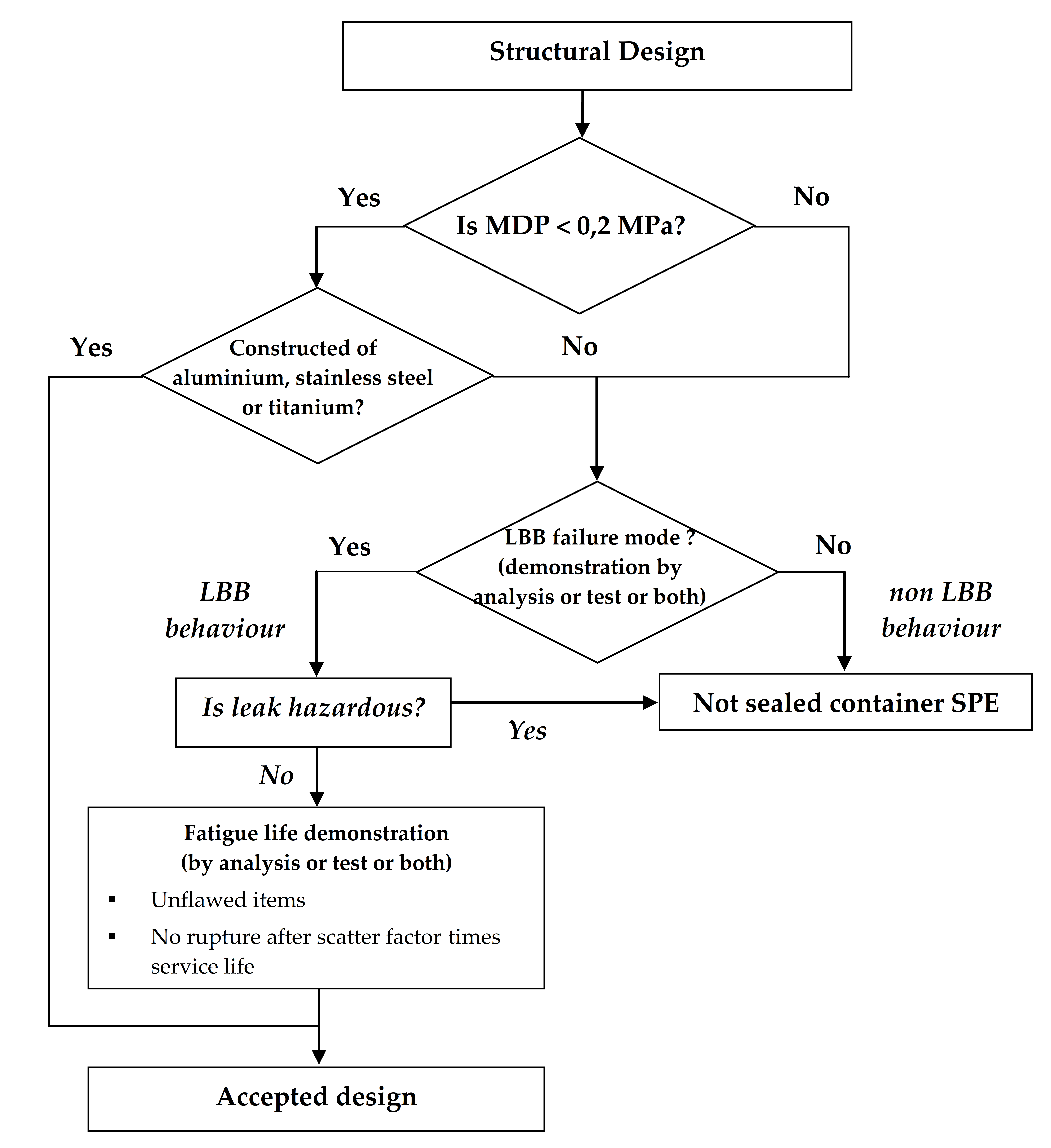 Figure 410: Development approach of sealed containers
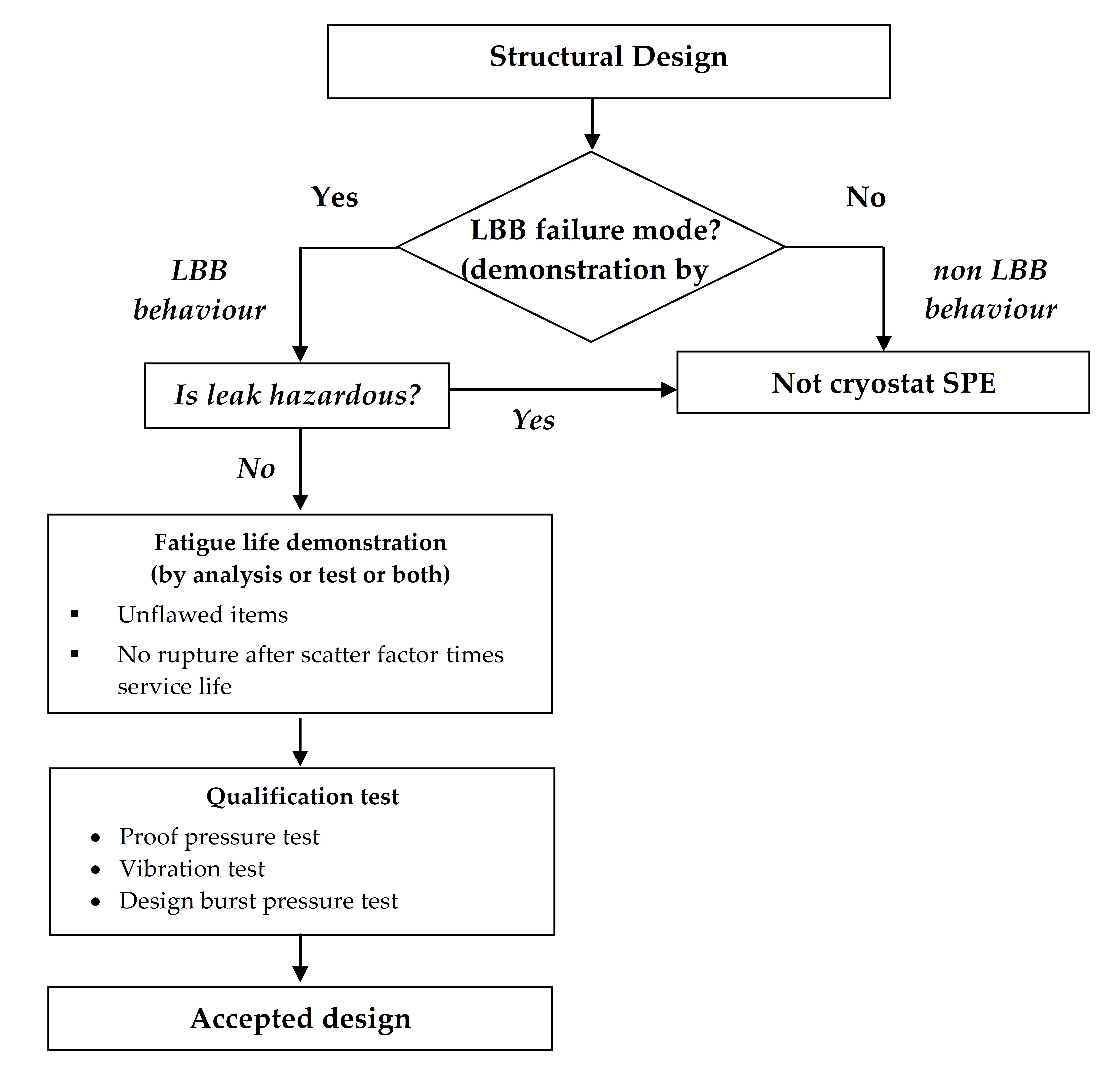 Figure 411: Development approach of cryostats (or Dewars)
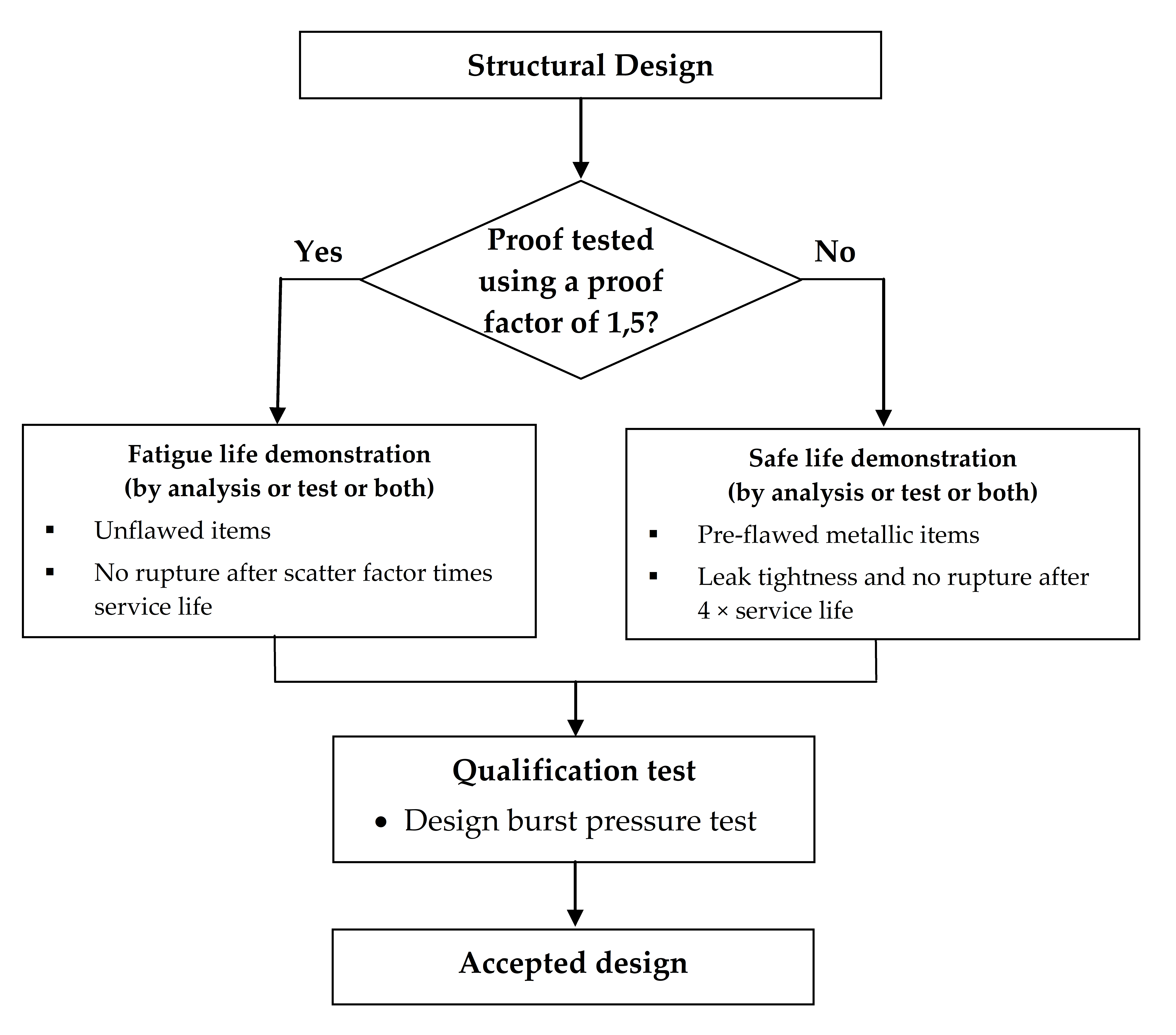 Figure 412: Development approach of heat pipes
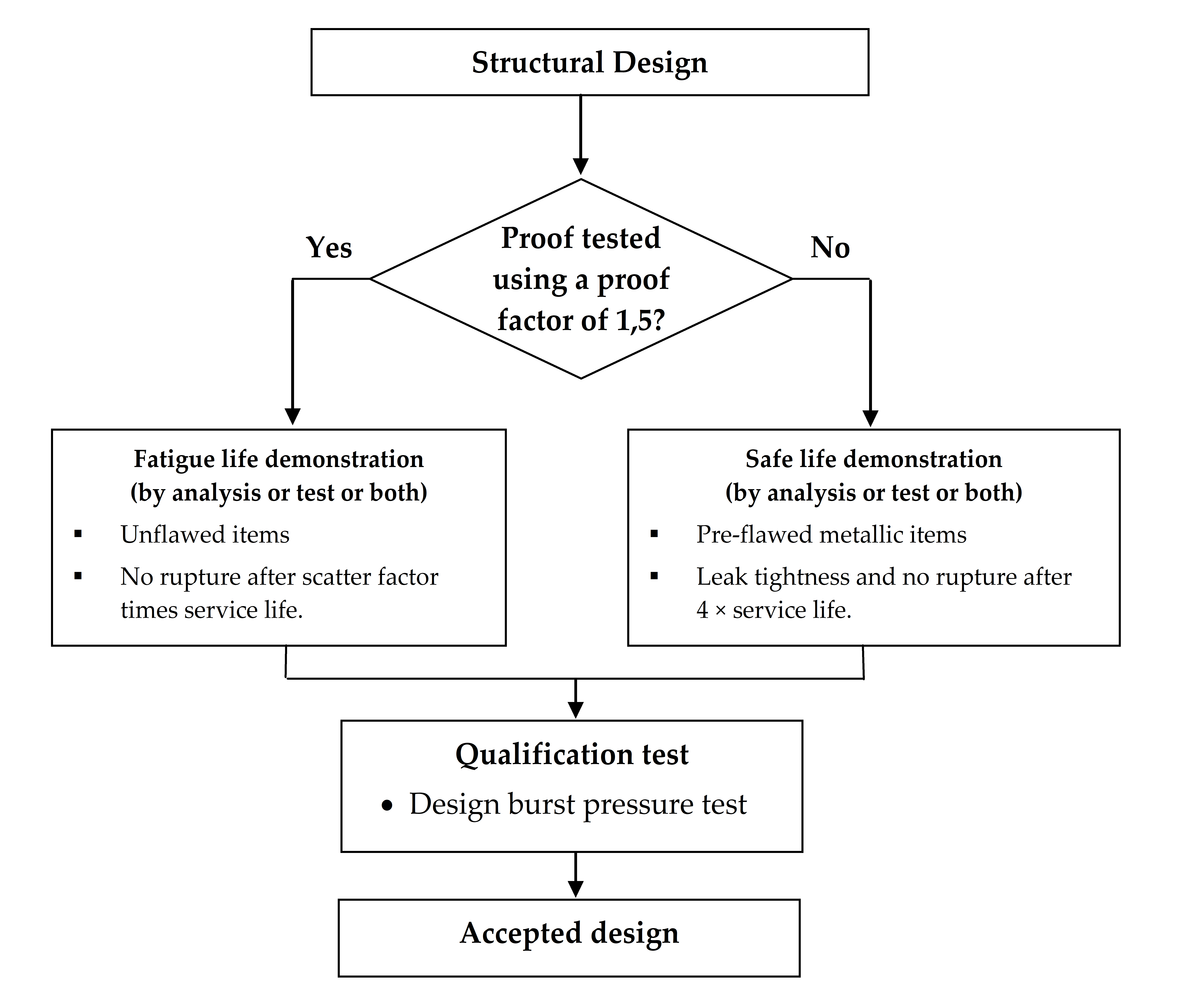 Figure 413: Development approach of hazardous fluid containers
Qualification tests
All cryostats shall be submitted to the following chronology of operations:
- proof pressure test;
- vibration tests;
- design burst pressure test.
All heat pipes and hazardous fluids containers shall be submitted to a design burst pressure test.
All batteries meeting the pressure vessel definition shall be submitted to the qualification tests as per clause 4.3.2.2.
For batteries meeting the pressure vessel definition, the qualification tests to be performed for functional performance shall be defined with customer approval.
Qualification leak test is sometimes replaced by thermal vacuum test.
Clauses 5.4.1, 5.4.2, 5.4.4 and 5.4.6, shall be applied to the qualification tests.
Acceptance tests
The following SPE shall be submitted to a proof pressure test:
- sealed containers with MDP greater than or equal to 0,2 MPa and exhibiting a LBB failure mode;
- cryostats;
- heat pipes;
- hazardous fluids containers.
Cryostats shall be NDI inspected prior to the proof pressure test.
Fusion joints shall be 100 % inspected by means of a NDI method, defined with customer approval, prior and after the proof pressure test.
All batteries meeting the pressure vessel definition shall be submitted to the acceptance tests as per clause 4.3.2.3.
For batteries meeting the pressure vessel definition, additional acceptance tests shall be defined for functional performance with customer approval.
Clauses 5.5.1, 5.5.2, and 5.5.3 shall be applied to the acceptance tests.
Proof and leak tests can be performed at the assembled pressurized system level.
COSPE with metallic liner
Factors of safety
The values in Table 49 shall be applied as minimum values of factors of safety for internal pressure.
The values specified in ECSS-E-ST-32-10 shall apply as minimum values of factors of safety for loads different from internal pressure.
Exceptions to the values provided in Table 49 are sometimes specified by the customer or granted with customer approval.
When this is the case for a burst factor, the following relations can be used for determination of the proof factor:
jproof = (1 + jburst) / 2 when jburst < 2,0
jproof = 1,5 when jburst > 2,0
TableTable 49: Factors of safety for COSPE with metallic liner (unmanned and manned missions)
|
Load
|
FOSY
|
Prooffactor
|
FOSU
|
Burstfactor
|
|
Internal pressure
|
1,0
|
1,25
|
1,0
|
1,5
|
|
Mechanical loads(including external pressure)
|
Values specified in ECSS-E-ST-32-10
| |||
Development approach
Clause 5.2 on structural engineering shall be applied.
A stiffness demonstration shall be performed by analysis and test.
A strength and stability demonstration shall be performed by analysis and test.
The failure mode shall be demonstrated by analysis or test or both according to clause 5.3.
The metallic liner of the COSPE shall exhibit a LBB failure mode.
‘Safe life item’ demonstration shall be performed for the metallic liner by analysis or test or both in conformance with ECSS-E-ST-32-01.
Fatigue-life demonstration shall be performed for the composite over-wrap by analysis or test or both in conformance with ECSS-E-ST-32.
Qualification tests shall be conducted in conformance with clause 4.6.2.3 to demonstrate the structural adequacy of the design.
For corrosion effects (control and prevention), the requirements in ECSS-E-ST-32 shall apply.
For hydrogen embrittlement phenomena, requirements shall be applied in conformance with ECSS-E-ST-32-08.
For material selection, material design allowables and their characterisation, requirements shall be applied in conformance with clause 5.6 and ECSS-E-ST-32.
For ‘process control’, requirements shall be in conformance with ECSS-Q-ST-70.
Inspections shall be applied according to clause 5.7.
The development approach is illustrated in Figure 44.
Qualification tests
A first qualification test article shall be submitted to the following chronology of operations:
- non-destructive inspection (NDI);
- proof pressure test;
- leak test;
- design burst pressure test;
- burst test.
The first qualification test article specified in 4.6.2.3a may be deleted with customer approval.
A second qualification test article shall be submitted to the following chronology of operations: - NDI;
- proof pressure test;
- leak test;
- vibration tests;
- pressure cycling test;
- leak test;
- design burst pressure test;
- burst test.
The leak test after proof pressure test specified in 4.6.2.3c, and the final burst test, specified in 4.6.2.3c may be deleted with customer approval.
When the vibration loads are enveloped by the other qualification tests, the vibration tests specified in 4.6.2.3c may be deleted with customer approval.
NDI operations shall be applied to the over-wrap, in addition to NDI on the liner.
Clause 5.4 shall be applied to the qualification tests.
The need to apply external loads in combination with internal pressure during testing shall be considered taking into account their relative magnitude, the fatigue and destabilizing effects of external loads.
If external cycling loads are applied, the load shall be cycled to limit for four times the predicted number of operating cycles of the most severe design condition.
Destabilizing load with constant minimum internal pressure or maximum additive load with a constant MDP.
Acceptance tests
All hardware shall be submitted to the following chronology of operations:
- initial NDI, in order to establish the initial condition of the hardware;
- proof pressure test;
- leak test;
- final NDI.
For example:
- The NDI prior to proof test can be substituted for that of the manufacturing process.
- Proof test monitoring by acoustic emission is acceptable for composite items instead of post testing NDI, with customer approval.
Initial NDI operations shall be applied to the over-wrap, in addition to NDI on the liner.
Clause 5.5 shall be applied to the acceptance tests.
Final NDI shall be performed on the over-wrap of the COSPE as a minimum.
COSPE with homogeneous non metallic liner
Factors of safety
The values in Table 410 shall be applied as minimum values of factors of safety for internal pressure.
The values specified in ECSS-E-ST-32-10 shall be applied as minimum values of factors of safety for loads different from internal pressure.
Exceptions to the values provided in Table 410 are sometimes specified by the customer or granted with customer approval.
When this is the case for a burst factor, the following relations can be used for determination of the proof factor:
jproof = (1 + jburst) / 2 when jburst < 2,0
jproof = 1,5 when jburst > 2,0
TableTable 410: Factors of safety for COSPE with homogeneous non metallic liner (unmanned and manned missions)
|
Load
|
FOSY
|
Prooffactor
|
FOSU
|
Burstfactor
|
|
Internal pressure
|
1,0
|
1,25
|
1,0
|
1,5
|
|
Mechanical loads(including external pressure)
|
Values specified in ECSS-E-ST-32-10
| |||
Development approach
Clause 5.2 on structural engineering shall be applied.
A stiffness demonstration shall be performed by analysis and test.
A strength and stability demonstration shall be performed by analysis and test.
The failure mode shall be demonstrated by test on full-scale article according to the requirements developed per clauses 5.3.1, 5.3.4 and 5.3.5.
The liner of the COSPE shall exhibit a LBB failure mode.
When the non-metallic liner of the COSPE remains in compression up to MDP and flaws do not propagate during the LBB test, the flaws pre-fabricated in the liner of the LBB full-scale specimen may be through cracks.
‘Safe life item’ demonstration shall be performed in accordance with ECSS-E-ST-32-01:
- by test for non-metallic items;
- by analysis or test or both for metallic items (e.g. metallic bosses).
Qualification tests shall be conducted according to clause 4.6.3.3 to demonstrate the structural adequacy of the design.
For corrosion effects (control and prevention), the requirements in ECSS-E-ST-32 shall apply.
Embrittlement control shall be applied in accordance with ECSS-E-ST-32-08.
For materials selection, material design allowables and their characterisation, requirements shall be applied in conformance with clause 5.6 and ECSS-E-ST-32.
For ‘process control’, requirements shall be in conformance with ECSS-Q-ST-70.
Inspections shall be applied according to clause 5.7.
The development approach is illustrated in Figure 45.
Qualification tests
A first qualification test article shall be submitted to the following chronology of operations:
- non-destructive inspection (NDI);
- proof pressure test;
- leak test;
- design burst pressure test;
- burst test.
The first qualification test article specified in 4.6.3.3a may be deleted with customer approval.
A second qualification test article shall be submitted to the following chronology of operations: - NDI;
- proof pressure test;
- leak test;
- vibration tests;
- pressure cycling test;
- leak test;
- design burst pressure test;
- burst test.
The leak test after proof pressure test specified in4.6.3.3c, and the final burst test specified in 4.6.3.3c may be deleted with customer approval.
When the vibration loads are enveloped by the other qualification tests, the vibration tests specified in 4.6.3.3c may be deleted with customer approval.
NDI operations shall be applied to the over-wrap, in addition to NDI on the liner.
Clause 5.4 shall be applied to the qualification tests.
The need to apply external loads in combination with internal pressure during testing shall be considered taking into account their relative magnitude, the fatigue and destabilizing effects of external loads.
If external cycling loads are applied, the load shall be cycled to limit for four times the predicted number of operating cycles of the most severe design condition.
Destabilizing load with constant minimum internal pressure or maximum additive load with a constant MDP.
Acceptance tests
All hardware shall be submitted to the following chronology of operations:
- initial NDI, in order to establish the initial condition of the hardware;
- proof pressure test;
- leak test;
- final NDI.
For example:
- The NDI prior to proof test can be substituted for that of the manufacturing process.
- Proof test monitoring by acoustic emission is acceptable for composite items instead of post testing NDI, with customer approval.
Initial NDI operations shall be applied to the over-wrap, in addition to NDI on the liner.
Clause 5.5 shall be applied to the acceptance tests.
Final NDl shall be performed on the over-wrap of the COSPE as a minimum.
Specific requirements
Overview
This clause presents the detail of requirements used in the development approach, qualification and acceptance of pressurized hardware.
These requirements are specific requirements in the sense that their applicability depends on the category of pressurized hardware, as presented in clauses 4.3 to 4.6.
The following requirements are included:
structural engineering;
failure mode demonstration;
damage control of pressurized composite hardware;
qualification tests;
acceptance tests;
composite over-wrap material characterisation;
inspection.
Structural engineering
The structural design of pressurized hardware shall be in conformance with ECSS-E-ST-32.
The effect of each operating parameter of the system (e.g. pressure regulator lock-up characteristics, valve actuation and water hammer) and any external loads and environments shall be considered for MDP determination.
Proof pressure and design burst pressure shall be derived from the MDP using the factor of safety given in clause 4.
The range of internal pressure shall be taken into account in the stiffness analysis (e.g. foreign frequency analysis).
As a minimum, any item of pressurized hardware shall possess, throughout the respective service life of the hardware in the expected operating environments, a strength such to withstand:
- proof pressure without detrimental deformation;
- design burst pressure without experiencing rupture or fibre failure;
- DYL and simultaneous internal pressure multiplied by FOSY for internal pressure without detrimental deformation;
- MDP multiplied by FOSY for internal pressure and simultaneous loads multiplied by FOSY for mechanical and thermal loads, without detrimental deformation;
- DUL and simultaneous internal pressure multiplied by FOSU for internal pressure without experiencing rupture or fibre failure;
- MDP multiplied by FOSU for internal pressure and simultaneous loads multiplied by FOSU for mechanical and thermal loads, without experiencing rupture or fibre failure;
- DUL and simultaneous external pressure multiplied by FOSU for mechanical and thermal loads, without experiencing rupture or fibre failure when pressurized to the minimum anticipated operating pressure.
The minimum internal pressure to guaranty structural stabilization shall be identified and included in the acceptance data package.
The pressurized hardware shall possess, throughout its service life in the expected operating environments, a stability such to withstand: - DUL and simultaneous external pressure multiplied by FOSU for pressure loads, without experiencing collapse when pressurized to the minimum anticipated operating pressure;
- DUL and simultaneous internal pressure without experiencing collapse. A scatter factor of five (5) shall be used in fatigue analysis.
Failure mode demonstration
General
The failure mode demonstration (i.e. demonstration of LBB or no LBB) can be ensured by analysis or test or both.
The choice of the demonstration methodology (i.e. analysis or test or both) shall conform to the requirements on failure mode demonstration specified in clauses 4.2 to 4.5 according to the type of pressurized hardware.
For example:
- Failure mode may be demonstrated by similarity with an existing analysis or test with customer approval.
- For new designs, without heritage, the demonstration by test is sometimes specified by the customer.
When failure mode is demonstrated by test, coupons or full-scale articles with prefabricated flaws shall be used as test specimens.
The failure mode shall be demonstrated for the structural items of the pressurized hardware, which serve as a fluid permeation barrier and which are primarily designed by pressure loads.
For example:
- For composite over-wrapped pressurized hardware, the liner is the fluid permeation barrier.
- For composite over-wrapped pressurized hardware, the boss area can be primarily designed by shear and not by pressure loads.
- For CPV and CPS, the composite wall itself is considered as the fluid permeation barrier.
When the failure mode demonstration is performed for metallic items, fracture mechanics principles shall be employed.
Areas where the LBB failure mode is not demonstrated shall be designed according to safe-life requirements as per clause 5.3.
For composite and composite over-wrapped pressurized hardware, potential degradation of the composite strength by the leaking fluid shall be accounted for in the failure mode demonstration.
Demonstration of LBB by analysis
It shall be shown that, at MDP, an initial surface crack with a flaw shape (a/c), ranging from 0,2 to 1,0, meets the following conditions:
- it does not fail as a surface crack; and
- it grows through the wall of the hardware to become a through crack with a length greater than or equal to 10 times the wall thickness of the metallic hardware item and remains stable.
For example:
- For a part-through surface crack, the crack aspect ratio is the ratio (a/c) of crack depth (a) to half crack length (c). For a part-through corner crack, the crack aspect ratio is the ratio (a/c) of crack depth (a) to crack length (c)/
- If no assumption is made about the initial surface crack size, the specified range a/c between 0,2 and 1,0 leads to a maximum through crack length of 2 c = 10 t (for a = t, where t is the wall thickness).
When LBB demonstration is based on a through crack with a length less than 10 times the wall thickness in accordance with 5.3.2a.2, the considered initial crack size shall be justified.
Justification of initial surface crack size can be based on NDI capability or on a crack whose depth is as close as possible to the wall thickness, within the range of a/c specified in clause 5.3.2a.
Demonstration of LBB by test using coupons
Coupons shall duplicate the materials (parent metals, weld joints, and heat affected zones) and the thickness of the metallic hardware items.
The coupon tests shall duplicate the loading conditions of the metallic hardware items.
Loading conditions include stress state aspects of bi-axial, compressive stresses parallel to crack plane.
The flaws shall be surface cracks and the flaw shape of the pre-fabricated surface cracks shall range from a/c = 0,2 to 1,0.
For the definition of a part-through surface crack, and a part-through corner crack see NOTE 1 in 5.3.2a.
The initial surface crack size shall be justified.
Justification of initial surface crack size can be based on NDI capability or on a crack whose depth is as close as possible to the wall thickness, within the range of a/c specified in 5.3.3c.
Stress (or strain) cycles shall be applied to the specimens with the maximum stress (or strain) corresponding to the MDP level and minimum stress (or strain) kept to zero, or actual minimum stress (or strain), until the surface crack grows through the specimen's thickness to become a through crack.
It shall be shown that the length of the through crack becomes equal to or greater than 10 times the specimen's thickness and remains stable at MDP.
Demonstration of LBB by test using full-scale article
The full-scale article shall be representative of the flight hardware.
The type and initial size of pre-fabricated flaws shall be justified.
Justification of initial flaw size can be based on NDI capability or on a crack whose depth is as close as possible to the wall thickness, within the range of a/c specified in sub clause5.3.4c.
For pre-flawed metallic items, the flaws shall be surface cracks and the aspect ratio of the pre-fabricated surface cracks shall range from a/c = 0,2 to 1,0.
For the definition of a part-through surface crack, and a part-through corner crack see NOTE 1 in 5.3.2a.
For pre-flawed composite items (liner or walls), the flaws may be through cracks with a length greater than or equal to 10 times the wall thickness of the item.
Location and orientation of pre-fabricated flaws shall be the most critical with regard to LBB response.
Pressure cycles shall be applied to the pressurized hardware, with the upper pressure equal to MDP and the lower pressure greater than or equal to zero.
After a flaw has grown through the thickness to become a through flaw and leakage has been detected, internal pressure shall be increased up to MDP.
At least one of the following conditions shall be satisfied after 5.3.4g has been met:
no burst occurs at MDP and leak rate is equal to or greater than a value defined with customer approval. This criteria is applicable to composite over-wrapped pressurized hardware, or
the length of the through crack in the metallic item becomes equal to or greater than 10 times the wall thickness of the item and remains stable at MDP. This criteria is only applicable to metallic and fully composite pressurized hardware.
Test fluid shall be compatible with the materials used in the hardware and not pose a hazard to test personnel.
The full-scale test shall duplicate the loading conditions and pressurization medium (gas or liquid) of the flight hardware.
E.g. loading conditions include stress state aspects of bi-axial, compressive stresses parallel to crack plane.
Report of LBB demonstration
When LBB is demonstrated by analysis:
- an analysis report in conformance with ECSS-E-ST-10-02 shall be prepared;
- in the report specified in 5.3.5a1, loading spectra, assumed initial flaw sizes, crack growth models, and fatigue crack growth rates shall be delineated. When LBB is demonstrated by test, a test report shall be prepared in conformance with ECSS-E-ST-10-02.
Qualification tests
General
‘General requirements’ and ‘Qualification testing’ requirements shall apply in conformance with ECSS-E-ST-10-03.
When the hardware mounting induces axial or radial restrictions on the pressure driven expansion of the hardware, the burst test fixture shall simulate the structural response or reaction loads of the flight mounting.
When a qualification test is conducted at temperature other than temperature expected for the design loads, the change of material properties at this temperature shall be verified:
by adjustment of the pressure and load level, or
by analysis, supported by tests on samples or sub-scale articles and providing material strength design allowable versus temperature.
When NDI is performed in the qualification tests, it shall meet clause 5.7.
The test fluids shall not deteriorate the test article.
The test fluids shall not pose a hazard to the test personnel.
When the strength design allowable of the materials depends on the fluid to be stored in the flight hardware (e.g. when the stored fluid is liquid hydrogen), the change of material properties shall be verified:
by using this specific fluid to pressurize the test specimens, or
by analysis, supported by tests on samples or sub-scale articles and providing material strength design allowable versus fluid characteristics.
In case of changing the manufacturing process, the qualification tests shall be repeated unless it is demonstrated that the new manufacturing process maintains or improves material and geometrical characteristics.
Proof pressure test
During the proof pressure test, the load level (i.e. pressure level, external load level) shall be maintained for 5 minutes as a minimum.
The interest for application of external loads in combination with internal pressures during testing shall be evaluated based on the relative magnitude, the destabilizing effect, or both, of stresses due to the external load.
Leak test
During the leak test, the pressure level shall be maintained at MDP or greater for 30 minutes as a minimum.
For qualification ‘leakage test’, requirements shall be in conformance with ECSS-E-ST-10-03.
Exceptions to the values provided in 5.4.3a and 5.4.3b are sometimes specified by the customer or granted with customer approval.
Vibration test
Vibration testing shall be conducted at the pressure condition corresponding to the maximum predicted vibration environment.
Operational conditions (e.g. fluid density, and filling ratio) shall be taken into account in the test configuration.
Pressure cycling test
Pressure cycles shall range from zero differential pressure to MDP and back to zero differential pressure for at least 50 cycles or four times the number of planned pressure cycles expected in one service life, whichever is greater.
Only cycles having a peak operating pressure that creates a liner tensile stress (exceeds the compressive metal liner pre-stress as imposed by the over-wrap, as a result of vessel autofrettage) shall be considered in the life cycle test of composite over-wrapped pressurized hardware.
Design burst pressure test
During the design burst pressure test, the design burst pressure level shall be maintained for 30 seconds as a minimum.
No burst or collapse shall occur prior to the end of the design burst pressure application.
Burst test
The pressure shall be increased until burst occurs.
The burst pressure shall be recorded.
Acceptance tests
General
‘General requirements’ and ‘Accepting testing’ requirements shall apply in conformance with ECSS-E-ST-10-03.
When an acceptance test is conducted at temperature other than temperature expected for the design loads, the change of material properties at this temperature shall be verified:
by adjustment of the pressure and load level, or
by analysis, supported by tests on samples or sub-scale articles and providing material strength design allowable versus temperature.
When NDI is performed in the acceptance tests, it shall meet clause 5.7.
When the strength design allowable of the materials depends on the fluid to be stored in the flight hardware (e.g. when the stored fluid is liquid hydrogen), the change of material properties shall be verified:
by using this fluid to pressurize the test specimens, or
by analysis, supported by tests on samples or sub-scale articles and providing material strength design allowable versus fluid characteristics.
Proof pressure test
During the proof pressure test, the load level (i.e. pressure level, external load level) shall be maintained for 5 minutes as minimum.
The interest for application of external loads in combination with internal pressures during testing shall be evaluated based on the relative magnitude, the destabilizing effect, or both, of stresses due to the external load.
Leak test
During the leak test, the pressure level shall be maintained at MDP or greater for 30 minutes as minimum.
For acceptance ‘leakage test’, requirements shall be in conformance with ECSS-E-ST-10-03.
Exceptions to the values provided in 5.5.3a and 5.5.3b are sometimes specified by the customer or granted with customer approval.
Composite over-wrap material characterization
Strength design allowable shall be generated from at least one of the following tests:
- elementary testing on samples or coupons, which are representative of the characteristics of the hardware;
- bursting of full or sub-scale specimens of different configurations, provided that applicability to the full scale article is demonstrated by analysis;
- bursting of sub-scale specimens, provided that scaling factor is accounted for;
- bursting of full-scale specimens.
Test results from at least two lots of yarns shall be used in the design allowable calculations unless all of the items are fabricated from the same lot of material.
When the composite wall of the pressurized hardware serves partially or totally as a permeation barrier (e.g. for CPV or CPS), any degradation of the wall due to the contact with the stored fluid shall be accounted for in the design allowable of material strength.
When in contact with liquid hydrogen, the composite wall can experience superficial micro-cracking and degradation of its transverse shear and tensile strength.
Inspection
General
An inspection plan shall be established prior to the start of fabrication.
For ‘Inspection’ plan, requirements shall be in conformance with ECSS-Q-ST-20.
For ‘Inspection of PFCI’, requirements shall be in conformance with ECSS-E-ST-32-01.
The inspection plan shall specify inspection points throughout the program, beginning with material procurement, continuing through fabrication, assembly, acceptance proof test and operation, and using the following techniques:
- procurement of raw materials, in conformance with ECSS-Q-ST-70;
- procurement of mechanical parts in conformance with ECSS-Q-ST-70;
- NDI for detecting mechanical damage or flaw, in conformance with clauses 5.7.2 and ECSS-E-ST-32-08.
Acceptance and rejection criteria shall be established within the inspection plan for each phase of inspection and for each type of inspection.
For ‘Detected defects’ outside of the acceptance criteria defined in 5.7.1e, requirements shall be in conformance ECSS-E-ST-32-01.
Inspection techniques for composite over-wraps and composites
After application of composite manufacturing process, any composite over-wrapped or composite item of pressurized hardware shall be subjected to the following inspections:
- visual inspection for detecting impact damage,
- state-of-the-art NDI techniques for inspecting mechanical damage or flaw induced on the composite.
Visual inspection shall be performed by inspectors, who have been trained to detect visible damage on composite or composite over-wrapped pressurized hardware involving the use of actual damaged hardware.
The NDI procedures are based on using multiple NDI methods to perform survey inspections or diagnostic inspections as follows: - survey NDI inspections shall be conducted when the location of the potential damage or flaw zone is unknown;
- diagnostic NDI inspections shall be performed within a localized suspect zone to characterize the type and extent of the damage or flaw.
All NDI techniques, whether used as a single inspection technique or as a combination of methods, shall have the capability to detect impact or flaw that can cause the composite over-wrapped or composite pressurized hardware to fail.
For ‘NDI for composite and bonded parts’, requirements shall be in conformance with ECSS-E-ST-32-01.
Bibliography
|
ECSS-S-ST-00
|
ECSS system - Description, implementation and general requirements
|