
Space product assurance
Materials and hardware compatibility tests for sterilization processes
Foreword
This Standard is one of the series of ECSS Standards intended to be applied together for the management, engineering and product assurance in space projects and applications. ECSS is a cooperative effort of the European Space Agency, national space agencies and European industry associations for the purpose of developing and maintaining common standards. Requirements in this Standard are defined in terms of what shall be accomplished, rather than in terms of how to organize and perform the necessary work. This allows existing organizational structures and methods to be applied where they are effective, and for the structures and methods to evolve as necessary without rewriting the standards.
This Standard has been prepared by the ECSS-Q-70-53 Working Group, reviewed by the ECSS Executive Secretariat and approved by the ECSS Technical Authority.
Disclaimer
ECSS does not provide any warranty whatsoever, whether expressed, implied, or statutory, including, but not limited to, any warranty of merchantability or fitness for a particular purpose or any warranty that the contents of the item are error-free. In no respect shall ECSS incur any liability for any damages, including, but not limited to, direct, indirect, special, or consequential damages arising out of, resulting from, or in any way connected to the use of this Standard, whether or not based upon warranty, business agreement, tort, or otherwise; whether or not injury was sustained by persons or property or otherwise; and whether or not loss was sustained from, or arose out of, the results of, the item, or any services that may be provided by ECSS.
Published by: ESA Requirements and Standards Division
ESTEC, P.O. Box 299,
2200 AG Noordwijk
The
Copyright: 2008 © by the European Space Agency for the members of ECSS
Change log
|
ECSS-Q-ST-70-53A
|
Never issued
|
|
ECSS-Q-ST-70-53B
|
Never issued
|
|
ECSS-Q-ST-70-53C
|
First issue
|
Introduction
A properly formulated and executed test program for all hardware elements that have to undergo sterilization is essential to guarantee their nominal performance and to prevent any immediate or long-term detrimental effects.
The detrimental effects to be anticipated during sterilization depend on the applied process and include
Direct effects: Materials degradation by heat, particulate and electromagnetic radiation, chemical interaction, cracking/fracture of materials or assemblies due to dimensional changes by expansion, out or off-gassing, etc.
Indirect effects: Change in crystallinity of materials, accelerated ageing (e.g. burn-in of components), heating due to radiation, generation of secondary radiation, re-contamination after out or off-gassing, etc.
Long-term effects: Generation of long-lived active centres (e.g. radicals) and subsequent post-degradation reactions, etc.
The objective of this Standard is to ensure a successful mission by the definition of a test protocol and acceptance criteria for the determination of hardware compatibility with sterilization processes.
Scope
This Standard describes a test protocol to determine the compatibility of materials, components, parts, and assemblies with sterilization processes. It is dedicated to test on non-flight hardware only. Any additional requirements that can be imposed by the potential use of test samples as flight hardware are not covered in this document (e.g. handling requirements). This Standard covers the following:
Identification of critical test parameters to establish functional integrity of the hardware.
Typical test protocols.
Acceptance criteria.
Statements about compatibility of materials and components with sterilization processes in this document are made in general terms only. Other factors for determination of whether a material or component is suitable for a particular mission system application include:
The potential number of sterilization cycles to which the material/component will be subjected in their live cycle.
The additional stresses on materials/components introduced when they have become part of a larger unit/equipment/system undergoing sterilization.
Compatibility of sterilization processes at e.g. materials level. This compatibility does not automatically guarantee that it will perform to its requirements in an assembly. The final application and possible interactions at higher assembly level are important considerations for qualification.
Qualification of hardware achieved by specific sterilization parameters. They cannot be necessarily extrapolated to other sterilization parameters, not even within the same sterilization process.
The drift in performance that can be induced by sterilization processes . This drift can cause equipments to fail to meet their specified performance requirements, even though each individual element/component remains within spec. An example of this is where ‘Select-on-test’ components are used to operate a component over a critically narrow range its full performance.
To assess ultimately the suitability/compatibility of a material or component for an application requires a full consideration of the impact of sterilization processes to which it is subjected during its whole life. This includes sterilization processes it undergoes from the time it is a standalone component/material right through to when it experiences final sterilization as part of the complete system.
This standard may be tailored for the specific characteristic and constrains of a space project in conformance with ECSS-S-ST-00.
Normative references
The following normative documents contain provisions which, through reference in this text, constitute provisions of this ECSS Standard. For dated references, subsequent amendments to, or revision of any of these publications do not apply, However, parties to agreements based on this ECSS Standard are encouraged to investigate the possibility of applying the more recent editions of the normative documents indicated below. For undated references, the latest edition of the publication referred to applies.
|
ECSS-S-ST-00-01
|
ECSS system – Glossary of terms
|
|
ECSS-Q-ST-20
|
Space product assurance – Nonconformance control system
|
|
ECSS-Q-ST-20
|
Space product assurance – Quality assurance
|
|
ECSS-Q-ST-20-07
|
Space product assurance – Quality assurance for test centres
|
Terms, definitions and abbreviated terms
Terms from other standards
For the purpose of this Standard, the terms and definitions from ECSSST0001 apply.
Terms specific to the present standard
direct effect
change of an intrinsic materials property that is caused by the interaction with a process parameter during application of a sterilization process
A direct effect might not be observed immediately after sterilization, but can be manifested over longer duration, see also ‘long duration effect’.
D-value, D10 value
time or dose required to achieve inactivation of 90 % of a population of the test micro-organism under stated conditions
[ISO 11139]
exposure time
period for which the process parameters are maintained within their specified tolerances
[ISO 11139]
indirect effect
effect that is not manifested as change in an intrinsic materials property but is the consequence of secondary interactions
Typical examples include molecular contamination during chemical sterilization, formation of radiolysis gas during γ-sterilization, bond breakage due to CTE mismatch during thermal sterilization.
effect that is caused by the interaction with a non-process parameter after application of a sterilization process
-
1 A typical example is post degradation because of interaction of oxygen from air with ‘active’ centres generated during the sterilization process.
-
2 An indirect effect might not be observed immediately after sterilization, but can be manifested over longer duration, see also ‘long duration effect’.
long duration effect
direct or indirect effect that is not manifested immediately after sterilization or post materials investigation but only after longer duration -
1 Typical examples are slow cross-linking of active centres and embrittlement of materials after γ-sterilization or induced corrosion followed from chemical conversion after chemical sterilization.
-
2 The time period after which long-duration effects become observable is materials and process specific, it can be as quick as days or as slow as years.
micro-organism
entity of microscopic size, encompassing bacteria, fungi, protozoa and viruses
[ISO 11139]
process parameter
specified value for a process variable
The specification for a sterilization process includes the process parameters and their tolerances.
[ISO 11139]
sterility
state of being free from viable micro-organisms
- 1 In practice, no such absolute statement regarding the absence of micro-organisms can be proven.
- 2 The definition of sterility in the context of this standard refers to the achievement of a required sterility assurance level.
[adapted from ISO 11139]
sterility assurance level
probability of a single viable micro-organism occurring on an item after sterilization
The term SAL takes a quantitative value, generally 10−6 or 10−3. When applying this quantitative value to assurance of sterility, an SAL of 10−6 has a lower value but provides a greater assurance of sterility than an SAL of 10−3.
[ISO 11139]
sterilization
validated process used to render product free from viable micro-organisms
In a sterilization process, the nature of microbial inactivation is exponential and thus the survival of a micro-organism on an individual item can be expressed in terms of probability. While this probability can be reduced to a very low number, it can never be reduced to zero.
[ISO 11139]
sterilization process
series of actions or operations needed to achieve the specified requirements for sterility
This series of actions includes pre-treatment of product (if necessary), exposure under defined conditions to the sterilizing agent and any necessary post treatment. The sterilization process does not include any cleaning, disinfection or packaging operations that precede sterilization.
[ISO 11139]
Abbreviated terms
For the purpose of this Standard, the abbreviated terms from ECSSSST-0001 and the following apply:
|
Abbreviation
|
Meaning
|
|
CTE
|
coefficient of thermal expansion
|
|
DSM
|
Deutsche Sammlung von Mikroorganismen(German Collection of Microorganisms)
|
|
DML
|
declared materials list
|
|
DMPL
|
declared mechanical parts list
|
|
DPL
|
declared process list
|
|
EEE
|
electrical, electronic, electromechanical
|
|
ESCC
|
European Space Components Coordination
|
|
ETFE
|
ethylene tetrafluoroethylene
|
|
ETO
|
ethylene oxide
|
|
GSE
|
ground support equipment
|
|
HDPE
|
high density polyethylene
|
|
IPA
|
isopropyl alcohol
|
|
ISO
|
International Organization for Standardization
|
|
LDPE
|
low density polyethylene
|
|
MIL-DTL
|
military detail specification
|
|
MIL-PRF
|
military performance specification
|
|
PCB
|
printed circuit board
|
|
PEEK
|
polyetheretherketone
|
|
PET
|
polyethylene terephthalate
|
|
PI
|
polyimide
|
|
POM
|
polyoxymethylene
|
|
PP
|
polypropylene
|
|
PPS
|
polyphenylene sulfide
|
|
PTFE
|
polytetrafluoroethylene
|
|
PUR
|
polyurethane
|
|
PVF
|
polyvinyl fluoride
|
|
OIT
|
oxygen induction time
|
|
OITP
|
oxygen induction temperature
|
|
SAL
|
sterility assurance level
|
|
UV
|
ultraviolet
|
Principles
Introduction to sterilization processes
Overview
Sterilization is a process killing all microorganisms. If there are survivors it is a bioburden reduction method. Sterilization processes are qualified in terms of probability to find one reference microorganism after their application, using the common and most resistant organism with respect to the sterilization method, named the SAL (Sterility Assurance Level). Independently of the method used - radiation, heat, gas - the reduction of microorganisms in time is in general a logarithmic curve, and follows ideally a straight line in a log diagram (see Figure 41). The sterilization parameter typically used for each process is D10, the time necessary to divide the microbial population by a factor of ten (10% survivor, also commonly called 1 log reduction, or one decimal reduction). Knowing the initial population (for example 104 microorganisms) and the specification to reach (for example SAL 10-6, meaning one microorganism for 106 items, or a 10-6 probability to find one microorganism on an item), the duration/dose will be 10 x D10. A 6 log reduction is the typical SAL for medical applications.
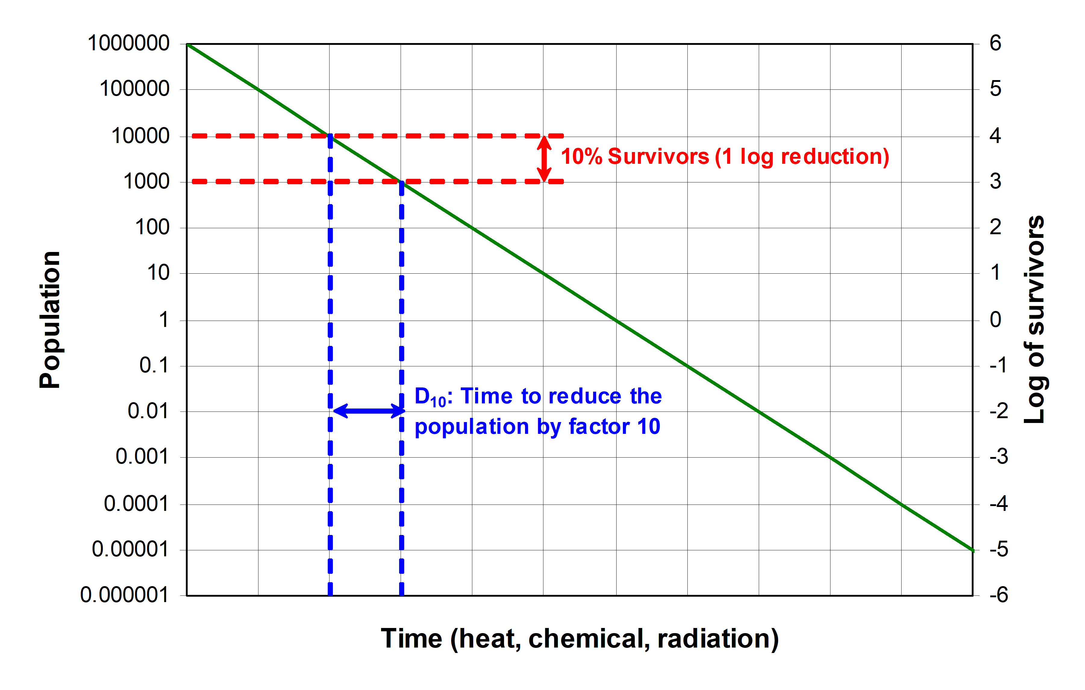 Figure 41: Sterilization parameters
In the following clauses a selection of potential sterilization processes for space hardware are described.
Dry heat
Dry heat is a bulk sterilization method. The effects of thermal sterilization on microorganisms depend on temperature, humidity and time. Typical parameters used for medical sterilization are given in Table 41. Qualified sterilization parameters to be used on flight hardware can deviate from these parameters. A typical microbiological indicator (most resistant of common microorganisms to dry heat) contains the spore B. atrophaeus DSM 675. The minimal temperature is 110 °C, below that the sterilization efficiency is considered insufficient. The maximum humidity level is 1.2 g/m3 water, otherwise the process is not considered as dry heat.
Depending on the specification, other temperature and time combinations can be used, validated via microbiological indicators. Thermal studies and tests may be necessary for large volumes and for complex equipment in order to homogenize as far as possible the temperature of the equipment.
Table 41:Time/temperature equivalences for SAL 10-6
|
T (°C)
|
D-value (h)
|
|
110
|
22
|
|
120
|
10
|
|
125
|
6
|
|
130
|
4
|
|
140
|
2
|
|
150
|
1
|
Beta or gamma radiation
Radiation is one of the most usual bulk sterilization processes used for medical devices. The typical dose for medical application is 25 kGy determined for the reference microorganism named B. pumilus DSM 492. Depending on the specification, other radiation doses can be used, validated via microbiological indicators.
Gamma rays are photons emitted from high activity radioactive cobalt 60 sources, a few 107 GBq usually, for a half life period of 5,27 years. The photon energies (1,17 and 1,33 MeV) are able to penetrate into several centimetres of steel. Beta radiations are electrons produced by particle generators and accelerators (30kV max). The electron energy, between 1 and 10 MeV max in order to avoid to break atom nuclei, allows a penetration depth of a few millimetre of steel. Compared to gamma radiations requiring minutes to hours of exposition, the dose rate of the beta process is very high and achieves a sterilization in only a few seconds to a few minutes.
Radiation sterilization is generally achieved inside a special blockhouse protecting, outside, the operators and the environment. In order to homogenize the radiation dose, the item is e.g. rotated around the source or revolved around one or two rotational axis. The dose and the dose rate are a function of the source activity and of the distance between the source and the sample.
Chemical sterilization
Overview
All kinds of chemical methods, using gas or liquid agents, are limited to sterilization of surfaces accessible for gas exchange. These processes are generally applied at temperatures below 60 °C.
Hydrogen peroxide (H2O2) sterilization
This method is known for its high degree of compatibility with high tech medical and surgical devices and instruments. The plasma phase destroys residual hydrogen peroxide before release of sterilized items. Methods using hydrogen peroxide gas without plasma are regarded as equally effective. Control of process parameters (humidity, pressure, gas concentration, time and temperature) is important.
Typical process parameters are the following:
Temperature: Typically (40 – 60) °C
Gas concentration typically between (4 - 10) g/m3 H2O2 in gas phase
Pressure: Ambient or mixed (vacuum/ambient) cycles
Duration typically 1 hour per cycle
Typical bioindicators for verification of the SAL for medical devices contain the B. Stearothermophilus DSM 5934. Gas sterilization methods are in general not suitable for parametric release.
Ethylene oxide (C2H4O)
This process results in extremely effective sterilization, using clearly established procedures. It is carried out in a closed medium (autoclaves) equipped with a gas stirring system. Typical parameters with an impact on the effectiveness of such sterilization are the following:
Temperature: 40 °C to 70 °C generally in a slightly depressurized atmosphere
Gas concentration of nominally between (5 - 8) g/m3 of pure gas (15 g/m3 max)
Relative humidity of minimum 30 %
Duration usually between 6 and 14 hours.
Typical bioindicators for verification of the SAL for medical devices contain typically the B. atrophaeus DSM 675 and B. Stearothermophilus DSM 5934.
In addition, after the sterilization process, sterile objects are taken into a warm-air desorption chamber (temperature 50 °C to 70 °C) for drawing out of virtually all residual gas that has diffused into or absorbed by the items or constituent materials (max. 2 ppm residual gas level specified for medical sterilization).
Due to the formation of non-volatile residues this sterilization poses a risk to contamination critical hardware.
Isopropyl alcohol
IPA (isopropanol) is the typical surface cleaning agent. It is not sporicidal, but a disinfectant (if applied in (60 – 70) % with water), but can be used in order to remove a large number of microorganisms from surfaces. IPA cleaning is usually used on space hardware, not only for biological cleanliness, and does not present particular incompatibilities. Without filtering alcohols are generally not sterile. In order to increase the bioburden reduction efficiency, sporicides can be used as for example alcohol containing a few percents of hydrogen peroxide or formaldehyde.
Steam sterilization
It is performed in autoclave in overpressure, at 100% of humidity, and therefore limited to sterilization of surfaces accessible for gas exchange. The efficiency depends on temperature, time and pressure (generally at 2 bar), typical procedures used for medical application require 20 minutes for 120 °C and 3 minutes for 134 °C. The sterilization effect is limited to surface.
Although not intended for flight hardware, steam sterilization can be a very useful process for e.g. GSE and tools.
Main methods used and studied in the field of space application
A summary of sterilization methods used for previous Mars missions is given in Table 42.
Table 42: Main sterilization methods used for space missions
|
Type
|
Methods
|
Sterilization type
|
Heritage
| ||
|
Surface
|
Bulk
|
Studied
|
Studied and used
| ||
|
CHEMICAL
|
Formaldehyde gas
|
X
|
--
|
Space components (US 1968)
|
--
|
|
Ethylen oxide (EtO)
|
X
|
--
|
-- |
Ranger 1961/62
| |
|
Sporicidal solution (TBD)
|
X
|
--
|
Mars 96
|
Mariner Mars 1971
| |
|
Hydrogen peroxide
|
X
|
--
|
--
|
Mars96, Beagle2, DS2
| |
|
THERMAL
|
Dry Heat
|
X
|
X
|
--
|
Viking, Mars96, Pathfinder, Beagle2, MER, , MSL
|
|
STEAM
|
Steam (space hardware excluded)
|
X
|
--
|
--
|
Excluded on space h/w, only GSE, garments
|
|
RADIATIVE
|
Gamma / Beta radiations
|
X
|
X
|
--
|
Mars96, Beagle2
|
Potential effects on hardware caused by sterilization
Direct effects
Changes of intrinsic materials properties as a consequence of the interaction with a process parameter from a sterilization process can depend on a variety of parameters, e.g. environment, material, assembly state, time, post environment. A direct effect might not be observed immediately after sterilization, but can be manifested over longer duration (see clause 4.2.3)
Indirect effects
Indirect effects can be caused by different mechanisms and are here classified into two categories:
Effects that are the consequence of secondary interactions. Typical examples include molecular contamination during chemical sterilization, formation of radiolysis gas during γ-sterilization, bond breakage due to CTE mismatch during thermal sterilization.
Effects that are caused by the interaction with a non-process parameter after application of a sterilization process. A typical example is post degradation because of interaction of oxygen from air with ‘active’ centres generated during the sterilization process.
An indirect effect might not be observed immediately after sterilization, but can be manifested over longer duration, see also ‘long duration effect’.
Long duration effects
Direct or indirect effects may not be manifested immediately after sterilization or post materials investigation but only after longer duration up to several years. Typical examples are slow cross-linking of active centres and embrittlement of materials after γ-sterilization or induced corrosion followed from chemical conversion after chemical sterilization.
Technology risks
A summary of technology risks is given in Annex D for guidance and preliminary assessment. The information provided within this Annex gives an overview of compatibility risks. It is a non-exhaustive list and the actual risk of degradation can deviate. Qualification cannot be deduced from this table and is evaluated on a case by case basis. Some means of risk mitigation are summarized below in case of incompatibility:
Replacement, e.g. change of material or component.
Redesign, e.g. use of fasteners instead of adhesives.
Sterilization on lower assembly level (if possible) and aseptic assembly.
Change of sterilization process.
If the alternative to dry heat sterilization (bulk) results in the application of a surface sterilization process, the remaining presence of bulk bioburden can be an issue for the overall bioburden of the spacecraft
Waiving sterilization.
Non-sterilized items can be used taking into account a conservative assessment of the present bioburden based on the applicable planetary protection requirements.
Qualification approach
As a consequence of potential detrimental effects on sterilized items (see clause 4.2), qualification of hardware is starting from materials/components level up to higher assembly level as appropriate. The qualification test flow diagram is shown in Figure 42.
To assess ultimately the suitability/compatibility of a material or component for an application requires a full consideration of the impact of sterilization processes to which it is subjected during its whole life. This includes sterilization processes it undergoes from the time it is a standalone component/material right through to when it experiences final sterilization as part of the complete system.
Compatibility of sterilization processes on e.g. materials level does not automatically guarantee that it performs to its requirements in an assembly. The final application and possible interactions on higher assembly level are important considerations for qualification.
Qualification of hardware achieved by specific sterilization parameters cannot be necessarily extrapolated to other sterilization parameters, not even within the same sterilization process.
Clause 5.1 provides the specification for the qualification of items for sterilization processes.
Clause 5.2 and 5.3 provide the requirements for preparing, performing, recording and reporting the qualification test.
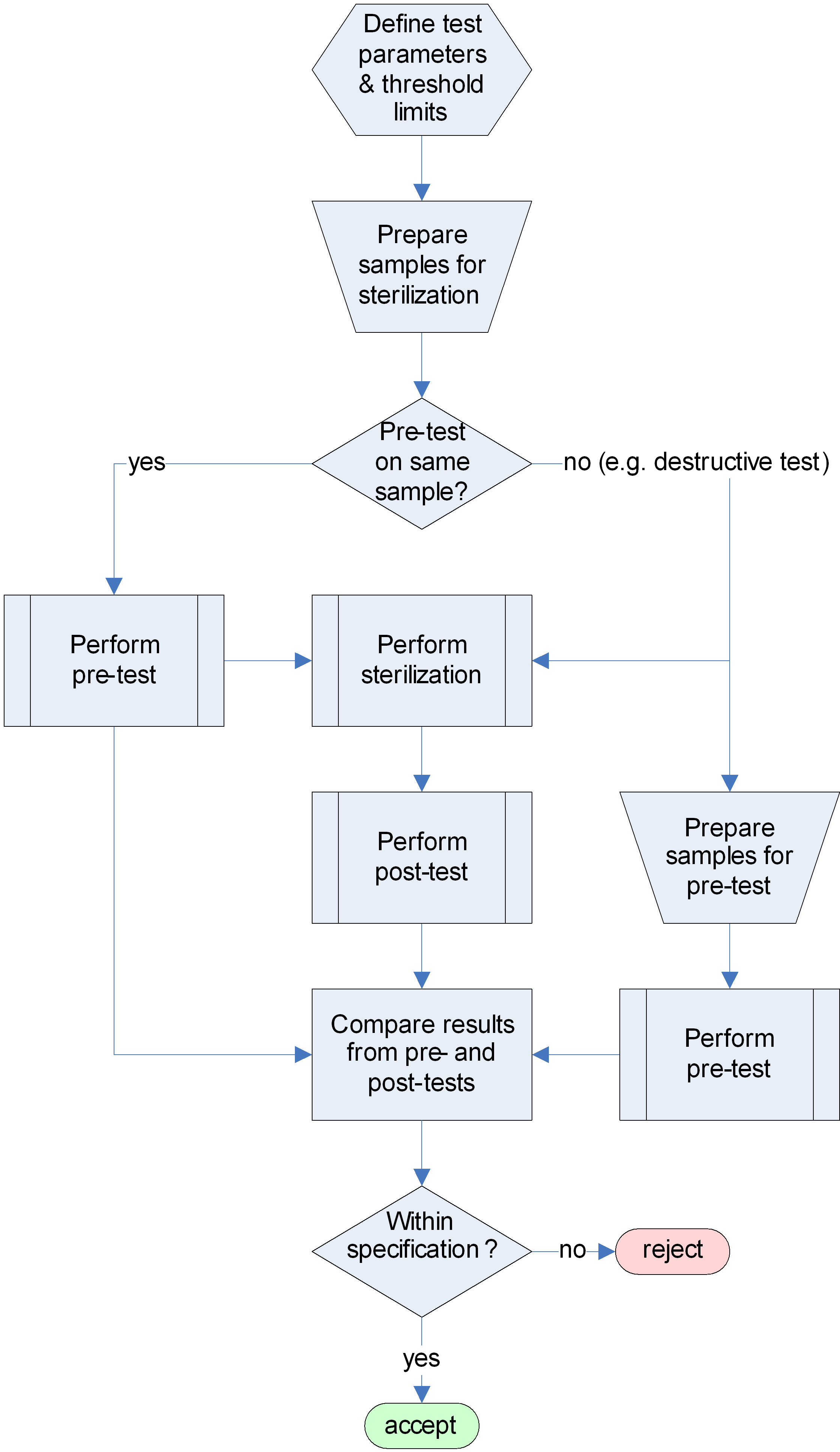 Figure 42: Test procedure flow diagram for sterilization
Requirements
Specifying test
General provision
The customer shall provide a request for a sterilization test in conformance with Annex A.
ECSS-Q-ST-20 shall be made applicable in the request for sterilization testing.
ECSS-Q-ST-10-09 shall be made applicable in the request for sterilization testing.
For safety and security, the test centre shall comply with ECSS-Q-ST-20-07, clause 9.
Examples of safety issues are hazard and health. Example of security issues is access control.
The supplier shall provide a sterilization compatibility test proposal in conformance with Annex B.
Specifying the test means
Facilities
The work area shall be at a cleanliness level that does not compromise the functionality of the test items or fulfil the imposed cleanliness requirements of the hardware.
The ambient conditions for the work areas shall be (22 ± 3) C with a relative humidity of (55 ± 10) % unless otherwise stated.
The supplier shall use sterilization facilities as described in Annex B.
- 1 Dry heat sterilization is described in ECSS-Q-ST-70-57, vapour phase (e.g. hydrogen peroxide) sterilization is described in ECSS-Q-ST-70-56.
- 2 Sterilization compatibility tests need to be conducted with the same process parameters intended for the flight hardware. For example compatibility with dry heat sterilization under ambient pressure does not compare to a vacuum process because of differences in thermal gradients.
Equipment
The supplier shall identify and specify the list of the equipment necessary to set up and run the approved test procedures.
Specifying the test procedure
Test procedure
The test procedures shall address the test conditions, control and monitoring of:
- Process parameters for sterilization.
Required process parameters for dry heat sterilization are described in ECSS-Q-ST-70-57, and for vapour phase (e.g. hydrogen peroxide) sterilization are described in ECSS-Q-ST-70-56.
- SAL.
- Contamination. The test procedure for controlling and monitoring the process parameters shall contain the following information:
- Process parameter measurement and recording methods.
- Process parameter acquisition during testing.
Controlling sterilization efficiency
In case of requirements to prove the sterilization efficiency (SAL), appropriate microbiological indicators shall be incorporated during sterilization and the following information provided for the test procedure:
- Microbiological indicator used during tests.
- SAL results.
- 1 Bioburden assessment procedures are described in ECSS-Q-ST-70-55.
- 2 Required microbiological indicators for dry heat sterilization are described in ECSS-Q-ST-70-57, and for vapour phase (e.g. hydrogen peroxide) sterilization are described in ECSS-Q-ST-70-56.
- 3 Besides the use of microbiological indicators, validation of process parameters can be used to verify SAL, in case the sterilization process is parametric (post parametric verification).
Controlling the contamination
In case of cleanliness requirements of the hardware to be tested, contamination effects shall be controlled and the following information provided for the test procedure:
- Contamination assessment methods used during tests.
- Contamination results.
Contamination can be induced by the sterilization process, e.g. in case of gas phase sterilization.
Preparing and performing test
General
The customer shall approve the sterilization compatibility test proposal including the procedures.
ECSS-Q-ST-20 shall apply for the establishment of the test procedures.
Preparation of hardware
Configuration
The material samples shall be prepared according to the relevant process specifications or manufacturer’s data, representative for its end-function and the flight hardware (e.g. batch).
Assemblies shall be representative for its end-function and the flight hardware.
If it is not possible to test completed assemblies, the manufacturer shall submit samples made from the same materials and by the same processes, sequence and configuration as those used in the manufacture of the assemblies, representative for its end-function and the flight hardware.
Cleaning
The cleaning and other treatments of the sample shall be the same as that applied to the flight hardware, which the sample is intended to represent, prior to integration into the spacecraft.
Further cleaning or other treatments require customer approval.
Handling and storage
Samples shall be handled with clean nylon or lint free gloves.
Storage of samples shall be performed in a controlled area, with an ambient temperature of (22 ± 3) °C and relative humidity of (55 ± 10) % unless stated otherwise.
Physical damage during storage shall be avoided by packing the items in clean, dust and lint free material.
Limited-life materials shall be labelled with their shelf lives and dates of manufacture.
For handling and storage of sterilized items refer to ECSS-Q-ST-70-57 (dry heat) and ECSS-Q-ST-70-56 (vapour phase).
Conditioning of hardware
Special conditioning required by the customer for the end-use shall be implemented.
Without representative conditioning the results of the test are not valid. For example the humidity content of a small witness sample that conditions much quicker cannot represent the conditions at use of full-sized flight hardware that has been packed and sealed after sterilization.
Identification
Items submitted for testing shall be labelled to be uniquely identifiable.
Labels attached prior sterilization shall be legible after the process.
A label can be degrading during the sterilization process and possibly affect the performance of the sterilized item (e.g. contamination, adherence to packaging).
Labelling shall contain as a minimum:
- Identification of item.
- Sterilization process.
- Date and contact information.
- Precaution and warning when applicable.
Pre and post tests
The inspection and test methods as well as the relevant parameters to verify the functionality of equipment after sterilization shall be specified by the customer before the application of each sterilization process.
The extent of physical, chemical, mechanical or electrical properties to be verified before and after sterilization depend on the intended application of the hardware (e.g. materials, components, parts, and assemblies).
For mechanical testing or other forms of destructive analysis, representative samples for the hardware shall be supplied for comparison of results before and after sterilization.
The samples for pre and post tests shall be provided from the same manufacturing batch.
Sterilization test
The supplier shall run the approved sterilization test procedures as described in Annex B.
All sterilization processes shall be performed in non-operational mode.
The sequence of sterilization with other hardware tests shall be defined by the customer.
The process parameters for sterilization, shall be defined by the customer.
The processes for dry heat and vapour phase (e.g. hydrogen peroxide) sterilization are described in ECSS-Q-ST-70-57 and ECSS-Q-ST-70-56 respectively.
The specified sterilization time shall start after all surfaces of a hardware item are exposed to the minimum sterilization condition.
- 1 Examples of sterilization conditions are: Temperature, radiation dose, or chemical reagent.
- 2 Sterilization is a time dependent process.
Margin for number of sterilization cycles: The need of multiple sterilization shall be foreseen.
The number of sterilization cycles for specified hardware shall be defined by the customer.
The number can vary for different hardware items.
The time delay between two sterilization cycles as well as the storage conditions shall be defined by the customer.
Sterilization, independent of whether achieved by physical or chemical means, can cause the formation of ‘hot’ (reactive) centres in materials. These sites can be long-lived and can result in secondary degradation effects (see clause 4.2). The simulation of several sterilization cycles cannot be achieved by simple extension of the sterilization time, but should take into account the complete process protocol as well as interaction with the external environment (e.g. different humidity levels) and possibly secondary effects.
Recording and reporting the test results
Test report
The supplier shall apply ECSS-Q-ST-20, clause 5.6.3.2 for the establishment of the test report.
The supplier shall provide the sterilization compatibility test report in conformance with Annex C for customer approval.
Test records
The test records of the sterilization test shall be retained for, at least, ten years or in accordance with customer requirements.
The test records of the sterilization test shall be composed of:
- The request for sterilization compatibility testing.
- The sterilization compatibility test proposal.
- The sterilization compatibility test report.
- A conclusion with respect to the compliance with the customer requirements (acceptance criteria) and associated nonconformances.
Acceptance criteria
Acceptance criteria shall be defined (beforehand) in common agreement between the test authority and the customer.
Traceability shall be maintained throughout the process from incoming inspection to final measurements and calculations, including details of the test equipment and personnel employed in performing the task.
Samples which have been tested and are not degraded within the defined limits by the execution of the approved sterilization test procedures shall be considered as having passed this test.
See clause 5.2.3.
The acceptance limits of degradation shall be allocated by the customer as part of the overall degradation budget including e.g. accumulation effects.
Synergistic or long-term degradation effects shall be considered if appropriate.
For example, parachute, airbags.
Stability of critical items during long term storage after sterilization shall be monitored by representative witness samples.
Drift of performance properties shall be taken into account if appropriate.
Drift can cause equipments to fail to meet their specified performance requirements, even though each individual element/component remains within specification. An example of this is where ‘Select-on-test’ components are used to operate a component over a critically narrow range its full performance.
ANNEX(normative)Request for sterilization compatibility test - DRD
DRD identification
Requirement identification and source document
This DRD is called from ECSS-Q-ST-70-53, requirements 5.1.1a.
Purpose and objective
The purpose of the request for sterilization compatibility testing is to confirm that the materials to be evaluated are acceptable for use
with respect to the specific sterilization test requirements of the customer, and
prior to its validation and approval for selection as item of the “as designed” DML, DPL or DMPL depending on the nature of the item to be tested (e.g. materials, processes or parts) .
Expected response
Scope and content
The Request for sterilization compatibility testing shall include or refer to the following information:
- Objective of the test activity.
- Background and justification to the test activity.
- Items to be investigated.
- Description of test activity.
- Deliverables.
Special remarks
None.
ANNEX(normative)Sterilization compatibility test specifications and procedures (Work Proposal) - DRD
DRD identification
Requirement identification and source document
This DRD is called from ECSS-Q-ST-70-53, requirements 5.1.1e.
Purpose and objective
The work proposal is a document that defines the test activity for sterilization compatibility of materials and hardware proposed by the test house. The work proposal for sterilization compatibility testing for materials and hardware is prepared by the test house, which is responsible for the test activity, and it is submitted to the customer for review and approval.
Expected response
Scope and content
The WP shall include or refer to the following information:
- A proposed work description giving:
- The objectives of the test activity.
- Test facilities, test procedures and reference to standards.
This includes, for example, sources.
* Traceable identification of items, materials, hardware.
* Test conditions.
I.e. environment, properties evaluated and measurement techniques.
* Expected test output.
- A proposed settlement describing the test procedures and any deviation from the conditions initially requested by the customer
A financial and administrative proposal including:
- Responsible person for the activity.
- List of deliverable items.
- Work breakdown structure defining the required operations and responsibilities.
I.e. preparation of specimens, testing, evaluation of results, reporting.
* Time schedule.
* Travel and subsistence plan (if applicable).
* Itemized cost list.
* Milestone payment plan.
Special remarks
None.
ANNEX(normative)Sterilization compatibility test report - DRD
DRD identification
Requirement identification and source document
This DRD is called from ECSS-Q-ST-70-53, requirements 5.3.1b.
Purpose and objective
The purpose of the sterilization compatibility test report is to provide quantitative evidence that the items were tested according to the sterilization compatibility test specifications and procedures.
Expected response
Scope and content
The sterilization compatibility test report shall include or refer to the following information:
- Description of the purpose, objective, content and the reason prompting its preparation.
- Description of the sterilization test facility.
- Description of the items to be tested or a reference to the document containing its identification characteristics.
For example: request for sterilization compatibility testing.
- Calibration tools.
- The test procedure or a reference to the document containing the description of the test procedure.
- 1 For example: sterilization compatibility test specifications and procedures DRD.
- 2 It often consist in describing the as- run test procedure as well as any deviation from the initial test procedure (including a discussion of possible effect on test).
- NCRs.
- Sterilization process parameters.
- The test results.
- Discussion about the test s results.
- Conclusion and recommendations. Test records shall be made available in electronic form for incorporation in a database defined by the customer, and contain as a minimum the following:
- Manufacturer.
- Traceable identification numbers for sterilised items.
For example: batch number, serial number.
- Sample description (type of application, size, colour, number of samples).
- Material name (trade name).
- Chemical nature.
- Thermal history / process parameters (for general materials property field).
- Intended application.
- Sterilization method, apparatus/facility, date.
- Nominal/measured sterilization parameters (e.g. temperature, radiation dose, gas concentration).
- Pre and post conditioning/storage parameters.
- Pre- and post sterilization values of test parameters defined in 5.2 including date of tests.
- Occurrence of NCRs.
- Copy of the final inspection documentation (attached docs in new tab).
- Copy of test reports (attached docs in new tab).
Special remarks
None.
ANNEX(informative)Technology risks of sterilization
General
A review of technology risks for space hardware sterilization has been carried out to indicate known detrimental effects. The evaluation is limited to the following typical processes:
Dry heat sterilization (typically 125 °C/48 h, 135 °C/12 h) considering multiple processes
Hydrogen peroxide sterilization (typically 4-10 mg/L H2O2 in gas phase, max 60 °C/40 min)
γ-Radiation sterilization (typically 25 kGy = 2,5 Mrad)
The described effects might not only lead to directly observed failures but can also cause indirect effects that are only manifested with the combined interaction of another environment such as solar irradiation or thermal cycling.
It is clear that such a review cannot be entirely exhaustive and does not provide sufficient information to omit appropriate qualification. Any piece of hardware (e.g. material, component, assembly) should be considered on its own within its individual boundary conditions.
Polymer (organic) materials
Dry heat sterilization
Overview
In case of dry heat sterilization it is important to recognize that it is not only the thermal environment that can affect hardware, but also that most commonly the process is performed with air, and thus provides a potentially oxidizing condition.
Temperature limit
A good indication of a material’s susceptibility to higher temperature is the qualification limit, but the presence of air should be considered in addition (see clause D.2.1.3). Otherwise potential damage can be caused by crossing a glass transition temperature, by reaching a decomposition temperature (e.g. polyurethanes ~150 °C), colourization (e.g. thermal control coatings), by mechanical stress due to CTE effects, etc.
In general the dry-heat sterilization process can be considered to induce accelerated ageing.
Presence of air (oxidizing)
The presence of oxygen during the dry heat sterilization process can lead to surface oxidation causing embrittlement and increase of hardness (e.g. seals), and colorization (e.g. thermal control coatings).
A thermal analysis screening test (e.g. differential scanning calorimetry) can be performed to assess the susceptibility of materials for oxidation by establishing the oxygen induction temperature (OITP) or oxygen induction time (OIT). The OITP is the temperature above which a rapid oxidation is observed, the OIT is the time after which the oxidation becomes significant for a given temperature.
Phase change materials
Sharp phase transitions induced by temperature can be used for actuation in various mechanisms. The thermal environment during sterilization can damage such devices.
Hydrogen peroxide sterilization
Some resins are known to react with hydrogen peroxide, e.g. it can attack secondary and tertiary amino groups in epoxy resins. Epoxy resins that are cross-linked with a larger amount of amino-curing agents tend to be more susceptible for degradation.
Materials that contain S-S linkages (e.g. sulphur vulcanised rubbers) can degrade due to oxidative attack of the sulphur bridges.
Process incompatibility: Scavenging (i.e. absorption) of hydrogen peroxide into materials, e.g. cellulose, poly urethane and polyamide can occur.
Process incompatibility: Catalytic decomposition of hydrogen peroxide by Cu, Ag, Mn.
The presence of hydrogen peroxide during the sterilization process can lead to surface oxidation causing embrittlement and increase of hardness (e.g. seals), and colorization (e.g. thermal control coatings) and paint chipping.
Diffusion of hydrogen peroxide into adhesive interfaces can affect the adhesive strength. In case adhesives are attached after sterilization, the process can change surface energy and thus adhesive strength.
Diffusion into the matrix of resins and reaction with filler particles (e.g. silver) is possible. This reduces the performance of respective electrically or thermally conductive coatings or resins. (e.g. grounding).
Velcro: Loss of 20% of peel strength have been observed -> 25% margin is recommended.
γ-Radiation sterilization
High energy radiation causes bond breakage leading to homolytic cleavage (free radical formation) or heterolytic cleavage (ion formation) of chemical bonds. Subsequently the ‘hot’ centres can undergo further transformations such as recombination (e.g. cross-linking), group transfer, or reaction with other molecules from the environment. The outgassing of radiolyses gas is possible. The physical effects can be competing, e.g. cross-linking can lead to embrittlement and increase in modulus, whereas termination reactions with low molecular weight species cause rather the reverse.
The reaction pathways depend very much on the nature and formulation of the materials, dose rate, temperature, time, etc., and are not predictable in a general sense. However, polymeric materials can be roughly classified in terms of their relative radiation stability as depicted in Figure D-1.
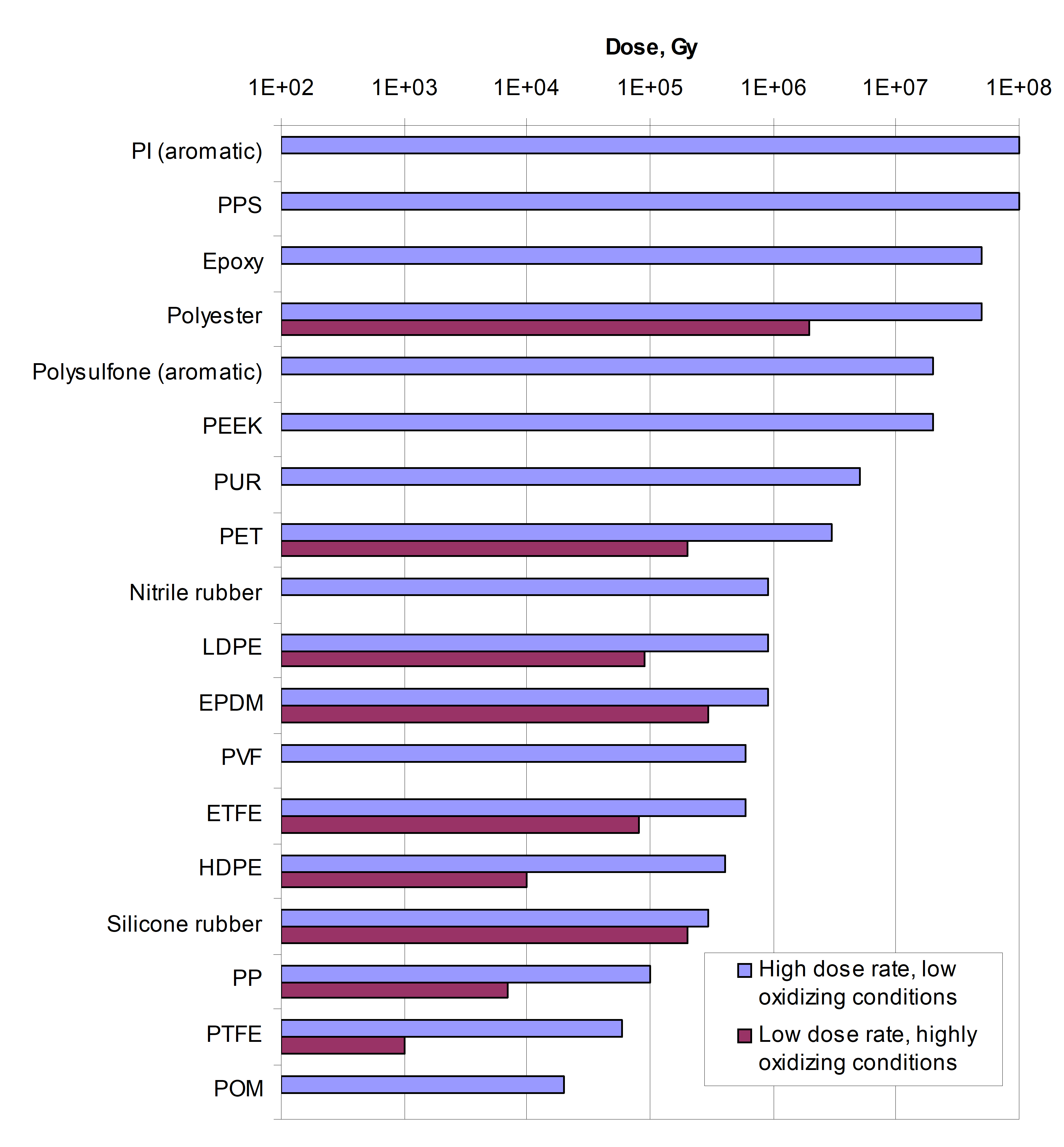 Figure: Relative radiation stability of polymers (see ref 1)
Effects such as radiation induced crosslinking from ETFE and reduction in maximum elongation of PA 6 have been observed.
Metallic materials
Dry heat sterilization
Precipitation hardened alloys
Alloys such as the Al 2000 and Al 7000 series can be precipitation hardened for increase of strength. This heat treatment leads to the maximum of strength following a defined aging process. Dry heat sterilization can cause the alloy to go beyond its critical aging parameters, leading to a decrease in yield strength. As an example, the Al 7025 may only be heated at 150 °C for 1000s. Softening of other aluminium alloys can also occur depending on their heat treatment and work hardening.
Low melting point
Indium has a melting point of 156 °C, but even lower temperatures can lead to creep and stress relaxation for seal applications, resulting in e.g. decrease in leak tightness.
Indium solder are used e.g. on gold, the melting point is < 120 °C.
Memory shape alloys
Actuation/damage of mechanisms that contain memory shape alloys can occur due to the thermal environment during sterilization.
Hydrogen peroxide sterilization
Oxidation
Silver is easily oxidised to Ag2O by H2O2. Although it is usually protected as it would also undergo oxidation on ground (especially by sulphur derivatives), pinholes in optical coatings with underlying silver layers or coatings of wires underneath insulation can be effected by H2O2 diffusion or penetration.
The H2O2 sterilization environment can increase the Al2O3 passivation layer on Al-coated optical surfaces. This is accompanied by a volume change and can be critical where geometry is crucial, e.g. for grating applications.
The protection systems for less corrosion resistant alloys are designed to be compatible with air in clean room environments, there compatibility with a more aggressive H2O2 environment should be assessed.
Sn/Pb solders: Lead can oxidise if exposed (normally behind conformal coating).
γ-Radiation sterilization
No risk expected, a critical threshold of 10MeV is not reached with sterilization conditions.
Ceramic materials
Dry heat sterilization
No detrimental effects expected with the exception of potential thermal stresses (see qualification temperature).
Hydrogen peroxide sterilization
Black anodization layers can fade during hydrogen peroxide sterilization. This has been observed if organic dyes are used. It should be noted that organic dyes are generally not accepted for space applications.
γ-Radiation sterilization
The ionizing radiation can cause formation of colour centres and consequently darkening in visible spectral range (e.g. optical windows, solar cell cover glasses). Cerium doped glasses are recommended to increase stability but result in a loss of a few % sterilization dose.
Lubricants
Dry heat sterilization
In case mild oxidation with air is a credible scenario see also clause D.2.1.3.
Hydrogen peroxide sterilization
The oxidizing environment can result in conversion of sulphide-based solid lubricants to the corresponding oxides (WS2 → WO2, MoS2 → MoO2), leading to increasing friction in mechanisms.
In addition the sulphides can react with hydrogen peroxide to sulphuric or sulphurous acid that can further damage materials.
γ-Radiation sterilization
Lubricants based on perfluoroethers are susceptible to ionizing radiation that can cause chain scission with subsequent group transfer and cross linking. These chemical conversion reactions have an influence on viscosity and therefore on the lubrication performance.
EEE components
Overview
See also ECSS-Q-ST-60 for EEE selection, control and procurement.
The performance of components can change to some extent after sterilisation (drift), which, although within manufacturer specification, can be critical for hardware design tolerance.
Dry heat sterilization
Table: Risk identification linked to dry heat sterilization
(Part 1 of 4)
|
Technology
|
Associated standards
|
Risks
|
Risks
|
|
125 °C/48h
|
135 °C/12h
| ||
|
Capacitors, chip,
|
ESCC 3009
|
No risk expected, possibly oxidation of end termination.max storage 150 °C
|
No risk expected, possibly oxidation of end termination.max storage 150 °C
|
|
Capacitors, molded, Ceramic
|
ESCC 3001, MIL-PRF-39014
|
No risk expected, possibly oxidation of end termination.max storage 150 °C
|
No risk expected, possibly oxidation of end termination. max storage 150 °C
|
|
Capacitors, glass
|
MIL-PRF-23269
|
No risk expected
|
No risk expected
|
|
Capacitors, mica
|
ESCC 3007, MIL-PRF-39001
|
No risk expected, possibly oxidation of end termination.max storage 150 °C
|
No risk expected, possibly oxidation of end termination.max storage 150 °C
|
|
Capacitors, chip, solid, tantalum (e.g. TAJ, T495, CWR11)
|
ESCC 3011
|
Maximum storage temperature is 125 °C
|
Damage or stressing will occur, failures likely
|
|
Capacitors, non-solid, tantalum, electrolytic (CLR79)
|
ESCC 3003
|
Maximum storage temperature is 125 °C
|
Damage or stressing will occur, failures likely
|
|
Capacitors, solid, tantalum, electrolytic (CSR type)
|
ESCC 3002
|
Maximum storage temperature is 125 °C
|
Damage or stressing will occur, failures likely
|
|
Capacitors, super metallized plastic film (CRH type)
|
ESCC 3006
|
Maximum storage temperature is 125 °C
|
Damage or stressing will occur, failures likely
|
Table D-1: Risk identification linked to dry heat sterilization
(Part 2 of 4)
|
Technology
|
Associated standards
|
Risks
|
Risks
|
|
Capacitors, metallized film, (HTP86, KM94S, PM94S, PM90SR2, MKT, …)
|
ESCC 3006
|
Maximum storage temperature is 125 °C
|
Damage or stressing will occur, failures likely
|
|
Connectors, non filtered, D-sub rectangular
|
ESCC 3401
|
Depending on maximum storage temp specified
|
Damage can occur
|
|
Connectors, filtered, D-sub rectangular and circular
|
ESCC 3405
|
Depending on maximum storage temp specified
|
Damage can occur
|
|
Connectors, printed circuit board
|
ESCC 3401
|
Depending on maximum storage temp specified
|
Damage can occur
|
|
Connectors, RF coaxial
|
ESCC 3402
|
Temperature limitations, max ratings are typically 105 °C depending on variants
|
Temperature limitations, max ratings are typically 105 °C depending on variants
|
|
Connectors, microminiature, rectangular
|
ESCC 3401
|
Depending on maximum storage temp specified
|
Damage can occur
|
|
|
ESCC 3501
|
Maximum rating 125 °C
|
Will present problems as outside of max rating
|
|
Diodes
|
ESCC 5000 MIL-PRF-19500
|
No problems expected as max rating is >150 °C
|
No problems expected as max rating is >150 °C
|
|
Diodes microwave
|
ESCC 5010
|
No problems expected as max rating is >150 °C
|
No problems expected as max rating is >150 °C
|
|
Filters
|
ESCC 3008
|
No problems expected
|
Exceeds max temperature ratings.
|
|
Fuses (CERMET) -
|
MIL-PRF-23419
|
No problems expected
|
No problems expected as AEM data sheet shows a derating curve to 150 °C
|
|
Heaters flexible
|
ESCC 4009
|
No problems expected
|
No problems expected
|
|
Inductors, coils, (moulded)
|
ESCC 3201
|
No problems expected, except for low Tg moulding compounds.
|
Exceeds max ratings and is determined by Tg of moulding compound
|
|
Inductors, coils (non moulded)
|
ESCC 3201
|
No problems expected
|
No problems expected
|
Table D-1: Risk identification linked to dry heat sterilization
(Part 3 of 4)
|
Technology
|
Associated standards
|
Risks
|
Risks
|
|
Integrated circuits
|
ESCC 9000
|
No problems expected
|
Storage to 150 °C for some devices- check Tmax ratings npte prolonged Al/Au intermetallics also Tg issues with PEMS
|
|
Integrated circuits microwave (MMIC)
|
ESCC 9010 MIL-PRF-38535
|
No problems expected
|
Exceeds max temperature ratings.
|
|
Microwave passive parts (circulators , isolators)
|
ESCC 3202 l
|
No problems expected for ESCC product. For commercial products verify temperature rating.
|
Exceeds max temperature ratings, complex assembly of polymer adhesives, encapsulates, etc.
|
|
Microwave passive parts (coupler, power dividers)
|
ESCC 3404 MIL-DTL-23971 (dividers)
|
No problems expected
|
Exceeds max temperature ratings, complex assembly of polymer adhesives, encapsulates, etc.
|
|
Microwave passive parts (attenuators, loads)
|
ESCC 3403
|
Temperature rating depends on technologies, varies from 85 °C to 165 °C
|
Temperature rating depends on technologies, varies from 85 °C to 165 °C
|
|
Oscillators (hybrids)
|
ECSS Q-ST-60-05
|
No problems expected
|
Higher temp can damage the crystal mounting
|
|
Relays, electromagnetic, latching and non-latching
|
ESCC 3601
|
No problems expected
|
Exceeds max temperature ratings.
|
|
Resistors, fixed, film (RNC and RLR type, except RNC90)
|
ESCC 4001
|
No problems expected
|
No problems expected
|
|
Resistors, high precision, fixed, metal foil (RNC90)
|
ESCC 4001
|
No problems expected
|
No problems expected
|
|
Resistors, network, thick film MDM
|
MIL-PRF-83401
|
No problems expected
|
No problems expected
|
|
Resistors, current sensing (RLV type)
|
MIL-PRF-49465
|
No problems expected
|
No problems expected
|
|
Resistors, power, fixed, wire-wound (RWR type)
|
ESCC 4002 MIL-PRF-39007
|
No problems expected
|
No problems expected
|
Table D-1: Risk identification linked to dry heat sterilization
(Part 4 of 4)
|
Technology
|
Associated standards
|
Risks
|
Risks
|
|
Resistors, power, fixed, wire-wound, chassis mounted (RER type)
|
ESCC 4003 MIL-PRF-39009
|
No problems expected
|
No problems expected
|
|
Resistors, precision, fixed, wire-wound (RBR type)
|
MIL-PRF-39005
|
No problems expected, max temperature rating is 145 °C
|
No problems expected, max temperature raring is 145 °C
|
|
Resistors, fixed, thick and thin film chip RM series
|
MIL-PRF-55342
|
No problems expected
|
No problems expected, although precision can be lowered slightly still in spec
|
|
Switches, electromechanical
|
ESCC 3701
|
No problems expected
|
Outside rating on some devices and thus damage can occur
|
|
Switches, thermostatic
|
ESCC 3702
|
No problems expected
|
No problems expected
|
|
Thermistors
|
ESCC 4006
|
Can be an issue depending on type and max rating
|
Can be an issue depending on type and max rating
|
|
Transformers
|
ESCC 3201
|
Can be an issue depending on type and max rating
|
Can be an issue depending on type and max rating
|
|
Transistors 3
|
ESCC 5000
|
No problems expected
|
No problems expected
|
|
Transistors 3microwave
|
ESCC 5010
|
No problems expected
|
No problems expected
|
|
Cables & wires, low Frequency4
|
ESCC 3901
|
No problems expected
|
No problems expected
|
|
Cables, coaxial, radio frequency4
|
ESCC 3902
|
No problems expected
|
No problems expected
|
|
Surface Acoustic Waves (SAW)
|
ESCC 3502
|
No problems expected
|
Exceeds max temperature ratings
|
|
Charge coupled devices (CCD)
|
ESCC 9020
|
No problems expected
|
No problems expected
|
|
Opto discrete devices Photodiodes, LED, Phototransistors Opto-couplers
|
ESCC 5000 MIL-PRF-19500
|
No problems expected with the exception of max. temperature rating for indium 100 °C (e.g. seals), precision of positioning of optical parts
|
Can be issues on the max temperature ratings
|
Hydrogen peroxide sterilization
Table: Risk identification linked to hydrogen peroxide sterilization
(Part 1 of 4)
|
Technology
|
Associated standards
|
Risks H202
|
|
4-10 g/mL H2O2 in gas phase, max 60 °C/40 min
| ||
|
Capacitors, chip,
|
ESCC 3009
|
Solderability or end termination affected, verification by test.
|
|
Capacitors, moulded, Ceramic
|
ESCC 3001, MIL-PRF-39014
|
Polymers can be affected by the hydrogen peroxide, verification with the manufacturers and oxidation of leads.
|
|
Capacitors, glass
|
MIL-PRF-23269
|
No risk expected
|
|
Capacitors, mica
|
ESCC 3007, MIL-PRF-39001
|
Solderability or end termination affected, verification by test.
|
|
Capacitors, chip, solid, tantalum (e.g. TAJ, T495, CWR11)
|
ESCC 3011
|
Organics and coatings could be compromised.
|
|
Capacitors, non-solid, tantalum, electrolytic (CLR79)
|
ESCC 3003
|
Hermetic device, no problems expected
|
|
Capacitors, solid, tantalum, electrolytic (CSR type)
|
ESCC 3002
|
Hermetic device, no problems expected
|
|
Capacitors, super metallized plastic film (CRH type)
|
ESCC 3006
|
Hermetic device, , no problems expected
|
|
Capacitors, metallised film, (HTP86, KM94S, PM94S, PM90SR2, MKT, …)
|
ESCC 3006
|
Hermetic device, , no problems expected
|
|
Connectors, non filtered, D-sub rectangular
|
ESCC 3401
|
Unlikely to cause any problems although ionic media could lead to issues. In addition metal finished needs to be specified as Ag or bare contacts areas could lead to oxidation problems.
|
|
Connectors, filtered, D-sub rectangular and circular
|
ESCC 3405
|
Unlikely to cause any problems although ionic media could lead to issues. In addition metal finished needs to be specified as Ag or bare contacts areas could lead to oxidation problems.
|
Table D-2: Risk identification linked to hydrogen peroxide sterilization
(Part 2 of 4)
|
Technology
|
Associated standards
|
Risks H202
|
|
4-10 g/mL H2O2 in gas phase, max 60 °C/40 min
| ||
|
Connectors, printed circuit board
|
ESCC 3401
|
Unlikely to cause any problems although ionic media could lead to issues. In addition metal finished needs to be specified as Ag or bare contacts areas could lead to oxidation problems.
|
|
Connectors, RF coaxial
|
ESCC 3402
|
Contamination issues for incorrect plated devices, correct metal finish to be ensured
|
|
Connectors, microminiature, rectangular
|
ESCC 3401
|
Unlikely to cause any problems although ionic media could lead to issues. In addition metal finished needs to be specified as Ag or bare contacts areas could lead to oxidation problems.
|
|
|
ESCC 3501
|
No problems expected as hermetic, oxidation of leads possible
|
|
Diodes
|
ESCC 5000 MIL-PRF-19500
|
Can be issues for glass packaged for penetration of oxidant.
|
|
Diodes microwave
|
ESCC 5010
|
Possibly issues for glass packages for penetration of oxidant.
|
|
Filters
|
ESCC 3008
|
Oxidant can penetrate the structure and cause degradation. Body could oxidise, usually made of silver.
|
|
Fuses (CERMET) -
|
MIL-PRF-23419
|
Possibly issues with the polymer/ package
|
|
Heaters flexible
|
ESCC 4009
|
Can be permeable to hydrogen peroxide Turk J Chem suggests can be.
|
|
Inductors, coils, (moulded)
|
ESCC 3201
|
Possibly issues with the polymer/ package
|
|
Inductors, coils (non moulded)
|
ESCC 3201
|
Possibly issues with the polymer/ package
|
|
Integrated circuits
|
ESCC 9000
|
Possibly issues with PEMS, no problems expected for hermetic devices
|
|
Integrated circuits microwave (MMIC)
|
ESCC 9010 MIL-PRF-38535
|
Possibly issues with PEMS, no problems expected for hermetic devices
|
|
Microwave passive parts (circulators , isolators)
|
ESCC 3202 l
|
Not hermetic, damaged can occur
|
|
Microwave passive parts (coupler, power dividers)
|
ESCC 3404 MIL-DTL-23971 (dividers)
|
Not hermetic, damaged can occur
|
Table D-2: Risk identification linked to hydrogen peroxide sterilization
(Part 3 of 4)
|
Technology
|
Associated standards
|
Risks H202
|
|
4-10 g/mL H2O2 in gas phase, max 60 °C/40 min
| ||
|
Microwave passive parts (attenuators, loads)
|
ESCC 3403
|
Depends on technologies, damage can occur
|
|
Oscillators (hybrids)
|
ECSS Q-ST-60-05
|
Hermetic device, no problems expected
|
|
Relays, electromagnetic, latching and non-latching
|
ESCC 3601
|
Damage can occur in case of penetration of hydrogen peroxide.
|
|
Resistors, fixed, film (RNC and RLR type, except RNC90)
|
ESCC 4001
|
Not hermetic, damage can occur
|
|
Resistors, high precision, fixed, metal foil (RNC90)
|
ESCC 4001
|
Not hermetic, damage can occur
|
|
Resistors, network, thick film MDM
|
MIL-PRF-83401
|
Epoxy resin package, possible compatibility issues
|
|
Resistors, current sensing (RLV type)
|
MIL-PRF-49465
|
High temp mould compound and metal terminals
|
|
Resistors, power, fixed, wire-wound (RWR type)
|
ESCC 4002 MIL-PRF-39007
|
Moulded or coated compound caution
|
|
Resistors, power, fixed, wire-wound, chassis mounted (RER type)
|
ESCC 4003 MIL-PRF-39009
|
Welded construction in silicon adhesive in A body No problems envisage
|
|
Resistors, precision, fixed, wire-wound (RBR type)
|
MIL-PRF-39005
|
Moulded or coated compound caution
|
|
Resistors, fixed, thick and thin film chip RM series
|
MIL-PRF-55342
|
No problems expected film with Silicon coating
|
|
Switches, electromechanical
|
ESCC 3701
|
Internal damage can occur
|
|
Switches, thermostatic
|
ESCC 3702
|
Internal damage can occur and cause problems with e.g. the disc and plunger.
|
|
Thermistors
|
ESCC 4006
|
Problems can occur, delicate construction.
|
|
Transformers
|
ESCC 3201
|
Materials can be damaged.
|
Table D-2: Risk identification linked to hydrogen peroxide sterilization
(Part 4 of 4)
|
Technology
|
Associated standards
|
Risks H202
|
|
4-10 g/mL H2O2 in gas phase, max 60 °C/40 min
| ||
|
Transistors 3
|
ESCC 5000
|
Hermetic device, no problems expected
|
|
Transistors 3microwave
|
ESCC 5010
|
Hermetic device, no problems expected
|
|
Cables & wires, low
|
ESCC 3901
|
No problems expected, although penetration of the wire can present problems.
|
|
Cables, coaxial, radio frequency4
|
ESCC 3902
|
No problems expected although penetration of the wire can present problems.
|
|
Surface Acoustic Waves (SAW)
|
ESCC 3502
|
Hermetic sealed device, no problems expected
|
|
Charge coupled devices (CCD)
|
ESCC 9020
|
Seal can be insufficient and allow penetration of hydrogen peroxide
|
|
Opto discrete devices Photodiodes, LED, Phototransistors Opto-couplers
|
ESCC 5000 MIL-PRF-19500
|
Hermetic device, no problems expected, although caution if using lens devices.
|
γ-radiation sterilization
Table: Risk identification linked to γ-radiation sterilization
(Part 1 of 3)
|
Technology
|
Associated standards
|
Risks radiation
|
|
25 kGy = 2.5 Mrad
| ||
|
Capacitors, chip,
|
ESCC 3009
|
No problems expected
|
|
Capacitors, molded, Ceramic
|
ESCC 3001, MIL-PRF-39014
|
Radiation damage can occur to the polymer.
|
|
Capacitors, glass
|
MIL-PRF-23269
|
No problems expected (ref 2)
|
|
Capacitors, mica
|
ESCC 3007, MIL-PRF-39001
|
No problems expected, known to be radiation stable.
|
|
Capacitors, chip, solid, tantalum (e.g. TAJ, T495, CWR11)
|
ESCC 3011
|
Radiation damage to the polymer can occur. Damage to coatings in layers possible too lead if internal damage to higher leakage. Verify.
|
|
Capacitors, non-solid, tantalum, electrolytic (CLR79)
|
ESCC 3003
|
Radiation leakage possible. Effect can be minimal.
|
|
Capacitors, solid, tantalum, electrolytic (CSR type)
|
ESCC 3002
|
Radiation leakage possible. Effect can be minimal.
|
|
Capacitors, super metallized plastic film (CRH type)
|
ESCC 3006
|
Radiation leakage possible. Assessment on case by case basis as dielectric is due to change from suppliers
|
|
Capacitors, metallised film, (HTP86, KM94S, PM94S, PM90SR2, MKT, …)
|
ESCC 3006
|
Radiation leakage possible. Assessment on case by case basis as dielectric is due to change from suppliers
|
|
Connectors, non filtered, D-sub rectangular
|
ESCC 3401
|
Radiation damage to polymer materials can occur, problems unlikely.
|
|
Connectors, filtered, D-sub rectangular and circular
|
ESCC 3405
|
Radiation damage to polymer materials can occur, problems unlikely.
|
|
Connectors, printed circuit board
|
ESCC 3401
|
Radiation damage to polymer materials can occur, problems unlikely.
|
|
Connectors, RF coaxial
|
ESCC 3402
|
No problems expected
|
|
Connectors, microminiature, rectangular
|
ESCC 3401
|
Radiation damage to polymer materials can occur, problems unlikely.
|
|
|
ESCC 3501
|
Radiation sensitive drifts can occur
|
Table D-3: Risk identification linked to γ-radiation sterilization
(Part 2 of 3)
|
Technology
|
Associated standards
|
Risks radiation
|
|
25 kGy = 2.5 Mrad
| ||
|
Diodes
|
ESCC 5000 MIL-PRF-19500
|
Does rate could affect these devices ELDRS. Radiation performances needs to be assessed on case by case basis.
|
|
Diodes microwave
|
ESCC 5010
|
Does rate could affect these devices ELDRS. Radiation performances needs to be assessed on case by case basis.
|
|
Filters
|
ESCC 3008
|
No problems expected
|
|
Fuses (CERMET) -
|
MIL-PRF-23419
|
No problems expected
|
|
Heaters flexible
|
ESCC 4009
|
Can be radiative breakdown
|
|
Inductors, coils, (moulded)
|
ESCC 3201
|
No problems expected, depending on encapsulant
|
|
Inductors, coils (non moulded)
|
ESCC 3201
|
No problems expected, depending on encapsulant
|
|
Integrated circuits
|
ESCC 9000
|
TID issues are likely
|
|
Integrated circuits microwave (MMIC)
|
ESCC 9010 MIL-PRF-38535
|
Assessment required.
|
|
Microwave passive parts (circulators , isolators)
|
ESCC 3202 l
|
Can damage devices through materials damage.
|
|
Microwave passive parts (coupler, power dividers)
|
ESCC 3404 MIL-DTL-23971 (dividers)
|
Can damage devices through materials damage.
|
|
Microwave passive parts (attenuators, loads)
|
ESCC 3403
|
Damage can occur depending on technologies
|
|
Oscillators (hybrids)
|
ECSS Q-ST-60-05
|
Radiation degradation on the crystal and supporting logic possible
|
|
Relays, electromagnetic, latching and non-latching
|
ESCC 3601
|
No problems expected although review of materials is advised.
|
|
Resistors, fixed, film (RNC and RLR type, except RNC90)
|
ESCC 4001
|
Degradation of film materials can occur
|
Table D-3: Risk identification linked to γ-radiation sterilization
(Part 3 of 3)
|
Technology
|
Associated standards
|
Risks radiation
|
|
25 kGy = 2.5 Mrad
| ||
|
Resistors, high precision, fixed, metal foil (RNC90)
|
ESCC 4001
|
Degradation of film materials can occur
|
|
Resistors, network, thick film MDM
|
MIL-PRF-83401
|
Epoxy resin package, degradation can occur
|
|
Resistors, current sensing (RLV type)
|
MIL-PRF-49465
|
High temp mould compound and metal terminals, no problems expected
|
|
Resistors, power, fixed, wire-wound (RWR type)
|
ESCC 4002 MIL-PRF-39007
|
Moulded or coated compound, no problems expected
|
|
Resistors, power, fixed, wire-wound, chassis mounted (RER type)
|
ESCC 4003 MIL-PRF-39009
|
Welded construction in silicon adhesive in a body, no problems expected
|
|
Resistors, precision, fixed, wire-wound (RBR type)
|
MIL-PRF-39005
|
Moulded or coated compound, no problems expected. However, special encapsulates are used internally to reduce stress for precision - effects of radiation unclear.
|
|
Resistors, fixed, thick and thin film chip RM series
|
MIL-PRF-55342
|
No problems expected film with Silicon coating
|
|
Switches, electromechanical
|
ESCC 3701
|
Internal damage can occur
|
|
Switches, thermostatic
|
ESCC 3702
|
Internal damage can occur
|
|
Thermistors
|
ESCC 4006
|
Materials damage can occur.
|
|
Transformers
|
ESCC 3201
|
Materials damage can occur.
|
|
Transistors 3
|
ESCC 5000
|
Radiation will affect the devices
|
|
Transistors 3microwave
|
ESCC 5010
|
Radiation will affect the devices
|
|
Cables & wires, low
|
ESCC 3901
|
Potential degradation of the insulator
|
|
Cables, coaxial, radio frequency4
|
ESCC 3902
|
Potential degradation of the insulator
|
|
Surface Acoustic Waves (SAW)
|
ESCC 3502
|
Problems if degradation of the Piezo occurs
|
|
Charge coupled devices (CCD)
|
ESCC 9020
|
Radiation will affect the devices
|
|
Opto discrete devices Photodiodes, LED, Phototransistors Opto-couplers
|
ESCC 5000 MIL-PRF-19500
|
Radiation will affect the devices
|
Batteries
Overview
The environmental limits of batteries are mainly defined by the susceptibility of separator and electrolyte to the exposed environment, affecting the mobility of charge carrier in short and/or long term.
In some cases electronics are integrated in batteries, e.g. in case of voltage restriction (see Annex D.6 for EEE components).
For qualification of batteries see ECSS-E-ST-20.
Dry heat sterilization
The key concern is the temperature; the maximum qualification temperature of a battery can be far below the temperature of a typical dry-heat sterilization cycle (e.g. Lithium ion batteries: typically (50 – 60) °C).
Hydrogen peroxide sterilization
Detrimental effects are limited to surface interaction and possibly damage of or penetration through seal.
γ-Radiation sterilization
Interactions are very specific to the used technology and electronics inside, for GEO missions test are typically performed up 2 kGy.
Explosive devices
Overview
The following considerations apply to pyrotechnic mixtures or compositions, primary explosives (e.g. lead azide, lead styphnate, tetrazene), pure high explosives (e.g. PETN, RDX, HMX, HNS), or high explosives with binders. Propellants are not considered.
For qualification of explosive devices, see ECSS-E-ST-33-11.
Dry heat sterilization
Problems can occur due to auto-ignition temperature, melting temperature or deterioration of reaction rate, explosive output (e.g. calorific, gas generation, detonation, shock-wave properties).
For compatibility with explosive devices, see ECSS-E-ST-33-11 clause 4.9 j, and k.
Hydrogen peroxide sterilization
Pyrotechnic device encapsulation needs to be compatible with hydrogen peroxide to ensure protection of the explosive.
For compatibility with explosive devices, see ECSS-E-ST-33-11 clause 4.9 a.
γ-Radiation sterilization
For Compatibility with explosive devices, see ECSS-E-ST-33-11 clause 4.14.4.2.
Solar cell assemblies
Overview
For qualification of solar cell assemblies see ECSS-E-ST-20-08.
Dry heat sterilization
In general no incompatibility is expected with current technologies. It should be noted that the temperature of the sterilization might be significantly higher than the operational environment and dominates the limit of qualification.
Hydrogen peroxide sterilization
In general no incompatibility is expected, possible interactions with the used adhesives should be considered (see clause D.2.2).
γ-Radiation sterilization
No incompatibility is expected for the photovoltaic cell for crystalline materials including Si and GaAs; possible detrimental effects in coverglass (clause D.4.3 or polymeric materials (clause D.2.3) should be considered.
PCBs, populated
Overview
For qualification of PCBs see ECSS-Q-ST-70-10.
Dry heat sterilization
Low Tg of matrix material from PCBs (e.g. epoxy) can cause stress in the Cu plating. Adhesives and conformal coatings underneath components can cause stress on solder joints due to CTE mismatch, especially with low Tg. Excessive growth of Sn/Cu intermetallic is possible on solder joints. The sterilization process should be considered during the verification of the assembly.
Hydrogen peroxide sterilization
Surface oxidation, e.g. of Pb from solders, is possible. Conformal coatings, compatible with the sterilization process, are preferred. For RF applications preference is given to selective plating (Sn/Pb and Au).
γ-Radiation sterilization
The main concern is related to the compatibility of components (see D.6.), compatibility with materials of the PCB should be considered.
Bibliography
|
ECSS-S-ST-00
|
ECSS system – Description, implementation and general requirements
|
|
ECSS-E-ST-20
|
Space engineering – Electrical and electronic
|
|
ECSS-E-ST-20-08
|
Space engineering – Photovoltaic assemblies and components
|
|
ECSS-E-ST-32-11
|
Space engineering – Explosive systems and devices
|
|
ECSS-Q-ST-60
|
Space product assurance – Electrical, electronic and electromechanical (EEE) components
|
|
ECSS-Q-ST-60-05
|
Space product assurance – Generic procurement of hybrids
|
|
ECSS-Q-ST-70-10
|
Space product assurance – Qualification of printed circuit boards
|
|
ECSS-Q-ST-70-55
|
Space product assurance – Microbial examination of flight hardware and cleanrooms
|
|
ECSS-Q-ST-70-56
|
Space product assurance – Vapour phase bioburden reduction for flight hardware
|
|
ECSS-Q-ST-70-57
|
Space product assurance – Dry heat bioburden reduction for flight hardware
|
|
NASA NPR 8020.12C
|
Planetary Protection Provisions for Robotic Extraterrestrial Missions
|