
Space engineering
Space data links - Telemetry transfer frame protocol
Foreword
This Standard is one of the series of ECSS Standards intended to be applied together for the management, engineering and product assurance in space projects and applications. ECSS is a cooperative effort of the European Space Agency, national space agencies and European industry associations for the purpose of developing and maintaining common standards. Requirements in this Standard are defined in terms of what shall be accomplished, rather than in terms of how to organize and perform the necessary work. This allows existing organizational structures and methods to be applied where they are effective, and for the structures and methods to evolve as necessary without rewriting the standards.
This Standard has been prepared by the ECSS-E-ST-50-03C Working Group, reviewed by the ECSS Executive Secretariat and approved by the ECSS Technical Authority.
Disclaimer
ECSS does not provide any warranty whatsoever, whether expressed, implied, or statutory, including, but not limited to, any warranty of merchantability or fitness for a particular purpose or any warranty that the contents of the item are error-free. In no respect shall ECSS incur any liability for any damages, including, but not limited to, direct, indirect, special, or consequential damages arising out of, resulting from, or in any way connected to the use of this Standard, whether or not based upon warranty, business agreement , tort, or otherwise; whether or not injury was sustained by persons or property or otherwise; and whether or not loss was sustained from, or arose out of, the results of, the item, or any services that may be provided by ECSS.
Published by: ESA Requirements and Standards Division
ESTEC, ,
2200 AG Noordwijk
The
Copyright: 2008 © by the European Space Agency for the members of ECSS
Change log
|
ECSS-E-50-03A
|
First issue
|
|
ECSS-E-50-03B
|
Never issued
|
|
ECSS-E-ST-50-03C
|
Second issue
|
Scope
This Standard contains the definition for Telemetry Transfer Frames which are fixed-length data structures, suitable for transmission at a constant frame rate on a space data channel.
The Telemetry Transfer Frame provides a standardized data structure for the transmission of space-acquired data over a telemetry space data link.
Usually, the source of the data is located in space and the receiver is located on the ground. However, this Standard may also be applied to space-to-space telemetry data links.
Further provisions and guidance on the application of this standard can be found, respectively, in the following publications:
The higher level standard ECSS-E-ST-50, Communications, which defines the principle characteristics of communication protocols and related services for all communication layers relevant for space communication (physical- to application-layer), and their basic relationship to each other.
The handbook ECSS-E-HB-50, Communications guidelines, which provides information about specific implementation characteristics of these protocols in order to support the choice of a certain communications profile for the specific requirements of a space mission..
Users of this present standard are invited to consult these documents before taking decisions on the implementation of the present one.
This standard may be tailored for the specific characteristics and constraints of a space project in conformance with ECSS-S-ST-00.
Normative references
The following normative documents contain provisions which, through reference in this text, constitute provisions of this ECSS Standard. For dated references, subsequent amendments to, or revisions of any of these publications, do not apply. However, parties to agreements based on this ECSS Standard are encouraged to investigate the possibility of applying the most recent editions of the normative documents indicated below. For undated references the latest edition of the publication referred to applies.
|
ECSS-S-ST-00-01
|
ECSS system – Glossary of terms
|
|
ECSS-E-ST-50-01
|
Space engineering – Space data links – Telemetry synchronization and channel coding
|
|
ECSS-E-ST-50-04
|
Space engineering – Space data links – Telecommand protocols, synchronization and channel coding
|
|
CCSDS 133.0B1
|
Space Packet Protocol – Blue Book, Issue 1, September 2003
|
|
CCSDS 135.0B3
|
Space Link Identifiers – Blue Book, Issue 3, October 2006
|
Terms, definitions and abbreviated terms
Terms from other standards
For the purpose of this Standard, the terms and definitions from ECSSST0001 apply.
Terms specific to the present standard
idle data
data which carries no information, but is sent to conform to timing or synchronization requirements
The bit pattern of idle data is not specified.
mission phase
period of a mission during which specified telemetry characteristics are fixed
The transition between two consecutive mission phases can cause an interruption of the telemetry services.
octet
group of eight bits
- 1 The numbering for octets within a data structure starts with 0.
- 2 Refer to clause 3.4 for the convention for the numbering of bits.
packet
variable-length data structure consisting of higher layer user data encapsulated within standard header information
static
unchanged within a specific virtual channel or within a specific master channel
This Standard contains requirements on the invariability, throughout one or all mission phases, of certain characteristics of the data structures specified in it.
Abbreviated terms
For the purpose of this Standard, the abbreviated terms from ECSSST0001 and the following apply:
|
Abbreviation
|
Meaning
|
|
ASM
|
attached sync marker
|
|
CCSDS
|
Consultative Committee for Space Data Systems
|
|
FECF
|
Frame Error Control Field
|
|
MSB
|
most significant bit
|
|
TM
|
Telemetry
|
Conventions
bit 0, bit 1, bit N−1
To identify each bit in an N-bit field, the first bit in the field to be transferred (i.e. the most left justified in a graphical representation) is defined as bit 0; the following bit is defined as bit 1 and so on up to bit N1.
 Figure 31: Bit numbering convention
most significant bit
When an N-bit field is used to express a binary value (such as a counter), the most significant bit is the first bit of the field, i.e. bit 0 (see Figure 31).
use of capitals for the names of data structures and fields
In this Standard initial capitals are used for the names of data structures and fields.
This enables field names to be easily identified in the surrounding text. For example, the field Transfer Frame Data Field is easier to see than transfer frame data field in text containing words such as frame and data and field.
It also prevents ambiguity over where the name begins and ends. For example, there are fields Transfer Frame Secondary Header and Transfer Frame Secondary Header Length. The capitals help the reader to distinguish between the Transfer Frame Secondary Header length (meaning ‘the length of the Transfer Frame Secondary Header’) and the Transfer Frame Secondary Header Length (meaning the field of that name).
Overview
General
The Telemetry Transfer Frame is a fixed-length data structure that provides an envelope for transmitting data units of several types over a telemetry space link. The frame is compatible with the ECSS standard for telemetry synchronization and channel coding defined in ECSS-E-ST-50-01.
The telemetry transfer frame protocol can operate in various configurations of the telemetry space link, depending on the telemetry channel coding scheme and security options selected. The correct operation of the protocol can only occur if a high-quality data channel is provided between the peer entities of the protocol.
- 1 The Standard for telemetry channel coding, ECSSEST-5001, defines the coding mechanisms for a high-quality data channel, including frame synchronization and randomization. CCSDS 350.0-G-2 describes the security options.
- 2 In this Standard the terms TM Transfer Frame and Telemetry Transfer Frame are used interchangeably, i.e. they are synonyms and have the same meaning as.
- 3 Annex D describes the mission configuration parameters within the scope of this Standard.
Physical channel
A data channel carrying a stream of bits in a single direction is referred to as a physical channel.
For the TM Transfer Frame specified in this Standard, the value of the Transfer Frame Version Number is constant for all frames of a physical channel.
The length of the frames for a given physical channel is fixed for a mission phase.
Master channels and virtual channels
The TM Transfer Frame supports the division of the physical channel into master channels and virtual channels by means of identifier fields in the frame header.
A master channel is identified by the values of the Transfer Frame Version Number and the Spacecraft Identifier. Within a given physical channel, a master channel consists of all the frames that have the same Transfer Frame Version Number and the same Spacecraft Identifier.
For a typical space mission, all the frames on a physical channel have the same value for the Spacecraft Identifier, so in this case there is one master channel on the physical channel. However, multiple master channels can share a physical channel, which, for example, can be the case when one spacecraft is transporting another spacecraft such as a probe.
A master channel is divided into virtual channels using the Virtual Channel Identifier field. This is a 3-bit field and therefore supports up to eight virtual channels on a master channel.
Sharing transmission resources
Virtual channels enable one physical channel to be shared among multiple higher-layer data streams, each of which can have different characteristics.
The mechanisms and parameters for sharing access by the virtual channels to the physical channel are implementation dependent and not within the scope of this Standard.
Data fields in the frame
Every TM Transfer Frame contains the Transfer Frame Data Field, which is the main data-carrying field in the frame. Within a virtual channel, the length of the Transfer Frame Data Field is static during a mission phase.
There are status fields in the frame header that are related to the use of the Transfer Frame Data Field. The Transfer Frame Data Field carries packets or other data units.
Additionally to the Transfer Frame Data Field, the TM Transfer Frame has two optional fields for carrying data:
The Transfer Frame Secondary Header, used to carry fixed-length mission-specific data.
The Operational Control Field, used to carry status information to control the operation of the telecommand space link or other spacecraft activities.
TM Transfer Frame
General
The TM Transfer Frame shall encompass the major fields, positioned contiguously if present, in the sequence shown in Figure 51.
- 1 Figure 51 shows the format of the TM Transfer Frame.
- 2 In the case that TM Transfer Frames are directly submitted to telemetry channel coding, the start of the TM Transfer Frame is always signalled by the attached sync marker (ASM) which immediately precedes the TM Transfer Frame. The ASM is specified in ECSS-EST-5001. When the TM Transfer Frame is embedded in a Reed-Solomon codeblock or turbo codeblock, the ASM signals the start of both.
Table 51: Major fields in a TM Transfer Frame
|
Field
|
Presence in TM Transfer Frame
|
Length in bits
|
|
Transfer Frame Primary Header
|
always
|
48
|
|
Transfer Frame Secondary Header
|
optional
|
16, 24, ... or 512
|
|
Transfer Frame Data Field
|
always
|
variable
|
|
Transfer Frame Trailer
|
optional
|
16, 32 or 48
|
The maximum length for a TM Transfer Frame shall be 2048 octets.
The TM Transfer Frame shall be of constant length throughout a specific mission phase.
Because a change of frame length also changes the time interval between the start of successive frames, it can result in a loss of synchronization at the data capture element.
The TM Transfer Frame length shall be in conformance with the specifications contained in the standard for telemetry channel coding, ECSS-EST-5001.
For some coding schemes, ECSS-E-ST-50-01 limits the TM Transfer Frame length to certain specific values.
TM Transfer Frames shall be transferred over a physical channel at a constant rate.
In order to assure correct decoding at the receiving end, the same telemetry channel coding options shall be applied to all TM Transfer Frames of a physical channel.
At the receiving end, TM Transfer Frames containing detected errors need not be delivered.
The handling of TM Transfer Frames containing detected errors shall be specified for each mission or mission phase.
Depending on the coding scheme in use, errors in a TM Transfer Frame can be detected during the telemetry channel decoding at the receiving end (see ECSS-E-ST5001). The Frame Error Control Field specified in clause 5.6 can be used to detect errors in TM Transfer Frames.
All TM Transfer Frames with the same Master Channel Identifier on a physical channel shall constitute a master channel.
- 1 The Master Channel Identifier is defined in clause 5.2.2.
- 2 In most cases, the master channel is identical to the physical channel. However, if the physical channel also carries TM Transfer Frames with other Spacecraft Identifiers, a distinction between the master channel and physical channel is made. In this case, multiplexing of TM Transfer Frames with different Spacecraft Identifiers is performed by multiplexing the different master channels on the same physical channel.
A master channel shall consist of between one to eight virtual channels.
On a physical channel that carries TM Transfer Frames, all the frames shall have the same Transfer Frame Version Number.
The TM Transfer Frames specified in this Standard do not share a physical channel with other types of frame.
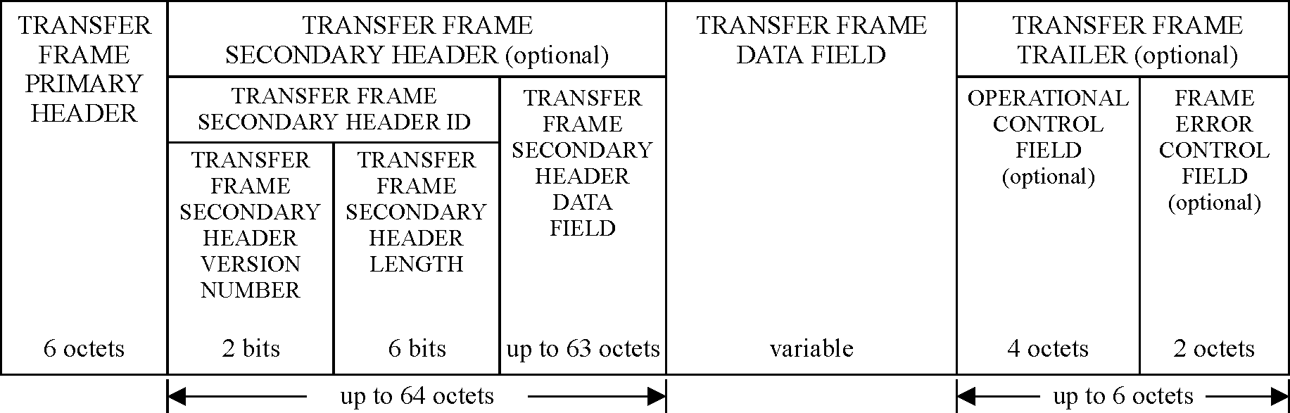 Figure 51: TM Transfer Frame format
Transfer Frame Primary Header
General
The Transfer Frame Primary Header shall always be present in a TM Transfer Frame.
The Transfer Frame Primary Header shall consist of six fields, positioned contiguously, in the following sequence:
- Master Channel Identifier 12 bits
- Virtual Channel Identifier 3 bits
- Operational Control Field Flag 1 bit
- Master Channel Frame Count 8 bits
- Virtual Channel Frame Count 8 bits
- Transfer Frame Data Field Status 16 bits
- 1 All six fields are always present in a Transfer Frame Primary Header.
- 2 Figure 52 shows the format of the Transfer Frame Primary Header.
- 3 The Transfer Frame Primary Header covers the following main functions:
- to identify the data unit as a TM Transfer Frame;
- to identify the master channel and virtual channel to which the frame belongs;
- to provide a counting mechanism for the virtual channels and the master channel;
- to provide status fields related to the data in the Transfer Frame Data Field.
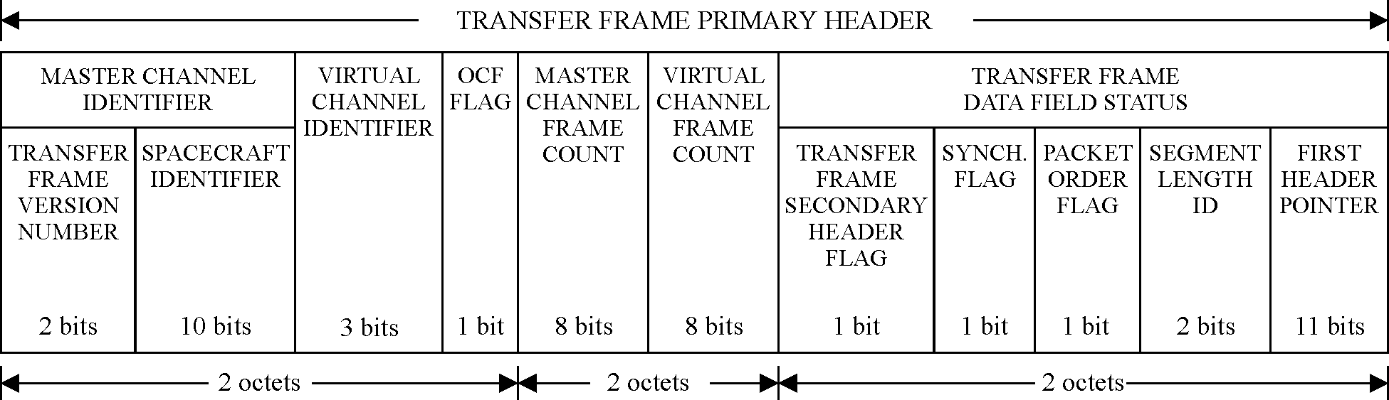 Figure 52: Format of Transfer Frame Primary Header
Master Channel Identifier
General
The Master Channel Identifier shall always be present in a Transfer Frame Primary Header.
The Master Channel Identifier shall be contained within bits 0-11 of the Transfer Frame Primary Header.
The Master Channel Identifier shall consist of two fields, positioned contiguously, in the following sequence:
- Transfer Frame Version Number 2 bits
- Spacecraft Identifier 10 bits
Both fields are always present in a Master Channel Identifier.
Transfer Frame Version Number
The Transfer Frame Version Number shall always be present in a Master Channel Identifier.
The Transfer Frame Version Number shall be contained within bits 0-1 of the Transfer Frame Primary Header.
The Transfer Frame Version Number shall be set to ‘00’.
This is the value defined in CCSDS 135.0-B-3 for the Transfer Frame Version Number of a TM Transfer Frame.
Spacecraft Identifier
The Spacecraft Identifier shall always be present in a Master Channel Identifier.
The Spacecraft Identifier shall be contained within bits 2-11 of the Transfer Frame Primary Header.
The Spacecraft Identifier shall provide the identification of the spacecraft which is associated with the data contained in the TM Transfer Frame.
- 1 The Secretariat of the CCSDS assigns Spacecraft Identifiers according to the procedures in CCSDS 320.0-B-4.
- 2 Different Spacecraft Identifiers can be assigned for normal operations and for development vehicles using the ground networks during pre-launch test operations, and for simulated data streams.
The Spacecraft Identifier shall be static throughout all mission phases.
Virtual Channel Identifier
The Virtual Channel Identifier shall always be present in a Transfer Frame Primary Header.
The Virtual Channel Identifier shall be contained within bits 12-14 of the Transfer Frame Primary Header.
The Virtual Channel Identifier shall provide the identification of the virtual channel to which the TM Transfer Frame belongs.
The order of occurrence of TM Transfer Frames belonging to different virtual channels on a master channel can vary.
Operational Control Field Flag
The Operational Control Field Flag shall always be present in a Transfer Frame Primary Header.
The Operational Control Field Flag shall be contained in bit 15 of the Transfer Frame Primary Header.
The Operational Control Field Flag shall indicate the presence or absence of the Operational Control Field, as follows:
- ‘1’ Operational Control Field is present;
- ‘0’ Operational Control Field is not present. The Operational Control Field Flag shall be static in the associated master channel or virtual channel throughout a mission phase.
See clause 5.5.1.
Master Channel Frame Count
The Master Channel Frame Count shall always be present in a Transfer Frame Primary Header.
The Master Channel Frame Count shall be contained within bits 16-23 of the Transfer Frame Primary Header.
The Master Channel Frame Count shall contain a sequential binary count (modulo 256) of each TM Transfer Frame transmitted in a specific master channel.
This field provides a running count of the frames transmitted through the same master channel.
The Master Channel Frame Count shall not be reset before reaching 255 unless there is a major system reset.
If the Master Channel Frame Count is reset due to a re-initialisation, the completeness of a sequence of TM Transfer Frames cannot be determined.
Virtual Channel Frame Count
The Virtual Channel Frame Count shall always be present in a Transfer Frame Primary Header.
The Virtual Channel Frame Count shall be contained within bits 24-31 of the Transfer Frame Primary Header.
The Virtual Channel Frame Count shall contain a sequential binary count (modulo 256) of each TM Transfer Frame transmitted through a specific virtual channel of a master channel.
This field provides individual accountability for the frames of each virtual channel. It can be used to detect gaps in the stream of data carried in the Transfer Frame Data Fields of the frames for a virtual channel.
The Virtual Channel Frame Count shall not be reset before reaching 255 unless there is a major system reset.
If the Virtual Channel Frame Count is reset due to a re-initialisation, the completeness of a sequence of TM Transfer Frames in the related virtual channel cannot be determined.
Transfer Frame Data Field Status
General
The Transfer Frame Data Field Status shall always be present in a Transfer Frame Primary Header.
The Transfer Frame Data Field Status shall be contained within bits 32-47 of the Transfer Frame Primary Header.
The Transfer Frame Data Field Status shall consist of five fields, positioned contiguously, in the following sequence:
- Transfer Frame Secondary Header Flag 1 bit
- Synchronization Flag 1 bit
- Packet Order Flag 1 bit
- Segment Length Identifier 2 bits
- First Header Pointer 11 bits
- 1 All these five fields are always present in a Transfer Frame Data Field Status.
- 2 This field indicates whether a secondary header is present and provides information relating to the data contained in the Transfer Frame Data Field.
Transfer Frame Secondary Header Flag
The Transfer Frame Secondary Header Flag shall always be present in a Transfer Frame Data Field Status.
The Transfer Frame Secondary Header Flag shall be contained in bit 32 of the Transfer Frame Primary Header.
The Transfer Frame Secondary Header Flag shall indicate the presence or absence of the Transfer Frame Secondary Header, as follows:
- ‘1’ Transfer Frame Secondary Header is present;
- ‘0’ Transfer Frame Secondary Header is not present.
The Transfer Frame Secondary Header Flag shall be static in a specific master channel, throughout a mission phase, when the Transfer Frame Secondary Header is associated with a master channel.
The Transfer Frame Secondary Header Flag shall be static in a specific virtual channel, throughout a mission phase, when the Transfer Frame Secondary Header is associated with a virtual channel.
Synchronization Flag
The Synchronization Flag shall always be present in a Transfer Frame Data Field Status.
The Synchronization Flag shall be contained in bit 33 of the Transfer Frame Primary Header.
The Synchronization Flag shall signal the formatting of the Transfer Frame Data Field, as follows:
- ‘0’ if octet-synchronized and forward-ordered packets or idle data are inserted;
- ‘1’ otherwise.
- 1 The values of the Packet Order Flag, the Segment Length Identifier and the First Header Pointer are also affected by the value of the Synchronization Flag. See clauses 5.2.7.4, 5.2.7.5 and 5.2.7.6.
- 2 When the Synchronization Flag is set to ‘0’, the value of the First Header Pointer is used to distinguish between packets and idle data as defined in clause 5.2.7.6.
The Synchronization Flag shall be static in a specific virtual channel throughout a mission phase.
Packet Order Flag
The Packet Order Flag shall always be present in a Transfer Frame Data Field Status.
The Packet Order Flag shall be contained in bit 34 of the Transfer Frame Primary Header.
If the Synchronization Flag is set to ‘0’, the Packet Order Flag shall be set to ‘0’.
- 1 When the Synchronization Flag is set to ‘0’, the Packet Order Flag is reserved for future use.
- 2 If the Synchronization Flag is set to ‘1’, the use of the Packet Order Flag is undefined.
Segment Length Identifier
The Segment Length Identifier shall always be present in a Transfer Frame Data Field Status.
The Segment Length Identifier shall be contained in bits 35-36 of the Transfer Frame Primary Header.
If the Synchronization Flag is set to ‘0’, the Segment Length Identifier shall be set to ‘11’.
- 1 This identifier was used in earlier standards to support an optional feature which is now obsolete. Its value is set to ‘11’ because this value indicates that the feature is not used.
- 2 If the Synchronization Flag is set to ‘1’, the Segment Length Identifier is undefined.
First Header Pointer
The First Header Pointer shall always be present in a Transfer Frame Data Field Status.
The First Header Pointer shall be contained in bits 37-47 of the Transfer Frame Primary Header.
If the Synchronization Flag is set to ‘0’, the First Header Pointer shall contain information on the data in the Transfer Frame Data Field, as specified in requirements 5.2.7.6d to 5.2.7.6g.
If the Synchronization Flag is set to ‘1’, the First Header Pointer is undefined.
If at least one packet starts in the Transfer Frame Data Field, the First Header Pointer shall contain the location of the first octet of the first packet that starts in the Transfer Frame Data Field.
If the last packet in the Transfer Frame Data Field of frame X spills over into frame Y of the same virtual channel (X<Y), the First Header Pointer in frame Y ignores the residue of the split packet and indicates the start of the first packet that starts in frame Y.
The locations of the octets in the Transfer Frame Data Field shall be numbered in ascending order starting with ‘0’.
If no packet starts in the Transfer Frame Data Field, the First Header Pointer shall be set to ‘11111111111’.
This can occur if a long packet extends across multiple frames.
If the Transfer Frame Data Field contains only idle data, the First Header Pointer shall be set to ‘11111111110’.
Transfer Frame Secondary Header
General
If present, the Transfer Frame Secondary Header shall follow, without gap, the Transfer Frame Primary Header.
The presence or absence of the Transfer Frame Secondary Header shall be signalled by the Transfer Frame Secondary Header Flag in the Transfer Frame Primary Header (see clause 5.2.7.2).
If present, the Transfer Frame Secondary Header shall comprise an integral number of octets: between 2 and 64 octets.
The Transfer Frame Secondary Header shall be associated with either a master channel or a virtual channel.
- 1 If the Transfer Frame Secondary Header is associated with a master channel, then the Transfer Frame Secondary Header is present in every frame on the master channel. In this case, the Transfer Frame Secondary Header has the same length for all virtual channels of the master channel.
- 2 If the Transfer Frame Secondary Header is associated with a given virtual channel, then the Transfer Frame Secondary Headers of other virtual channels can be absent or can be used for other purposes. For example, the Transfer Frame Secondary Header can have a different length on different virtual channels.
The Transfer Frame Secondary Header shall have a fixed length in the associated master channel or in the associated virtual channel throughout a mission phase.
The Transfer Frame Secondary Header shall consist of two fields, positioned contiguously, in the following sequence: - Transfer Frame Secondary Header Identification 8 bits
- Transfer Frame Secondary Header Data Field 8, 16, ... or 504 bits
- 1 Both fields are always present in a Transfer Frame Secondary Header.
- 2 The format of the Transfer Frame Secondary Header is shown in Figure 51.
The Transfer Frame Secondary Header shall be used to carry fixed length data defined at mission level.
The Transfer Frame Secondary Header may be used to provide an extended virtual channel frame count as specified in clause 5.3.4.
Transfer Frame Secondary Header Identification
General
The Transfer Frame Secondary Header Identification shall always be present in a Transfer Frame Secondary Header.
The Transfer Frame Secondary Header Identification shall be contained in bits 0-7 of the Transfer Frame Secondary Header.
The Transfer Frame Secondary Header Identification shall comprise two fields, positioned contiguously, in the following sequence:
- Transfer Frame Secondary Header Version Number 2 bits
- Transfer Frame Secondary Header Length 6 bits
Both fields are always present in a Transfer Frame Secondary Header Identification.
Transfer Frame Secondary Header Version Number
The Transfer Frame Secondary Header Version Number shall always be present in a Transfer Frame Secondary Header Identification.
The Transfer Frame Secondary Header Version Number shall be contained in bits 0-1 of the Transfer Frame Secondary Header.
The Transfer Frame Secondary Header Version Number shall be set to ‘00’.
This field indicates which of, up to, four secondary header versions is used. This Standard only recognizes one version: Version 1 which is represented by setting the field to the binary value ‘00’.
Transfer Frame Secondary Header Length
The Transfer Frame Secondary Header Length shall always be present in a Transfer Frame Secondary Header Identification.
The Transfer Frame Secondary Header Length shall be contained in bits 2-7 of the Transfer Frame Secondary Header.
The Transfer Frame Secondary Header Length shall contain the total length of the Transfer Frame Secondary Header in octets minus one, represented as a binary number.
When a Transfer Frame Secondary Header is present, this length can be used to compute the location of the start of the Transfer Frame Data Field.
The value of the Transfer Frame Secondary Header Length shall be static within a specific master channel or a specific virtual channel throughout a mission phase.
Transfer Frame Secondary Header Data Field
The Transfer Frame Secondary Header Data Field shall always be present in a Transfer Frame Secondary Header.
The Transfer Frame Secondary Header Data Field shall follow, without gap, the Transfer Frame Secondary Header Identification Field.
The Transfer Frame Secondary Header Data Field shall contain the Transfer Frame Secondary Header data.
Extended virtual channel frame count
Overview
The Transfer Frame Secondary Header may provide an extended virtual channel frame count. The following requirements apply in when the extended virtual channel frame count is used.
Using the extended count
The length of the Transfer Frame Secondary Header shall be 32 bits.
The Transfer Frame Secondary Header has a length of 4 octets, so the Transfer Frame Secondary Header Length contains the value 3.
The Transfer Frame Secondary Header Data Field shall contain the 24-bit extension to the virtual channel frame count.
The extension to the virtual channel frame count shall be a binary count of the roll-overs of the 8-bit value contained in the Virtual Channel Frame Count in the Transfer Frame Primary Header.
This provides a 32-bit count, with the most significant 24 bits in the Transfer Frame Secondary Header Data Field and the least significant 8 bits in the Virtual Channel Frame Count.
The use of the extended virtual channel frame count shall be associated with either a master channel or a virtual channel.
- 1 If the extended virtual channel frame count is associated with a master channel, then the Transfer Frame Secondary Header of every frame on the master channel contains the extended count. However, the value of the extended count in a given frame is the value for the virtual channel to which the frame belongs.
- 2 If the extended virtual channel frame count is associated with a virtual channel, then the Transfer Frame Secondary Headers of other virtual channels can be absent or used for other purposes.
The use of the extended virtual channel frame count shall be static in the associated master channel or in the associated virtual channel throughout a mission phase.
Transfer Frame Data Field
Overview
As specified in clause 5.1, the length of a TM Transfer Frame is static throughout a mission phase. The lengths of the optional parts of the frame (Transfer Frame Secondary Header, Operational Control Field and Frame Error Control Field) are static in the associated virtual channel, master channel or physical channel throughout a mission phase. As a result, the length of the Transfer Frame Data Field for a virtual channel is static throughout a mission phase.
In general, the Transfer Frame Data Field contains data to be transmitted over the space link on behalf of higher layers.
For TM Transfer Frames where the Synchronization Flag (clause 5.2.7.3) is set to ‘0’, the Transfer Frame Data Field carries packets in the manner specified in clause 5.4.3.
This Standard does not specify the data carried in the Transfer Frame Data Field for TM Transfer Frames where the Synchronization Flag is set to ‘1’. The data can consist of packets or any other data units.
clause 5.4.4 specifies an optional use of the Transfer Frame Data Field to carry asynchronously inserted data. The specification in clause 5.4.4 does not restrict the use of the Transfer Frame Data Field of frames where the Synchronization Flag is set to ‘1’.
General
The Transfer Frame Data Field shall always be present in a TM Transfer Frame.
The Transfer Frame Data Field shall follow, without gap, one of the following:
If a Transfer Frame Secondary Header is present, the Transfer Frame Secondary.
If a Transfer Frame Secondary Header is not present, the Transfer Frame Primary.
The length of the Transfer Frame Data Field shall be an integral number of octets and be constrained by the length of the total TM Transfer Frame.
The constraints on the length of a TM Transfer Frame are specified in clause 5.1.
Packet processing and extraction functions
Overview
For TM Transfer Frames where the Synchronization Flag is set to ‘0’, the Transfer Frame Data Field carries packets. Clauses 5.4.3.3, 5.4.3.4 and 5.4.3.5 apply in this case.
The First Header Pointer (clause 5.2.7.6) indicates the position of the first packet which starts in the Transfer Frame Data Field.
The functions for processing the packets depend on knowledge of the position, size and meaning of certain fields in the standard packet headers. Clause 5.4.3.3 specifies some of the properties of the packets.
Clause 5.4.3.4 specifies the packet processing function at the sending end, which places the packets into the Transfer Frame Data Fields in a sequence of TM Transfer Frames for a virtual channel. Clause 5.4.3.5 specifies the function at the receiving end which extracts the packets from the Transfer Frame Data Fields.
Meeting timing conditions
In a system which transmits TM Transfer Frames at a constant rate, there are timing conditions on the rate at which frames are generated at the sending end:
If no data is available for insertion into a Transfer Frame Data Field at release time for a frame, a Transfer Frame Data Field containing idle data can be created. Clause 5.2.7.6 defines a special value for the First Header Pointer in this case. If the Transfer Frame Data Field contains only idle data, the frame is sometimes referred to as an only idle data transfer frame. However, such a frame can transmit valid data carried in the Transfer Frame Secondary Header and the Operational Control Field.
If insufficient data is available for insertion into a Transfer Frame Data Field at release time for a frame, then one or more idle packets can be created to occupy space in a Transfer Frame Data Field. Clause 5.4.3.3 defines these idle packets.
Packet properties
A packet handled by the packet processing and extraction functions shall have a defined Packet Version Number in conformance with CCSDS 135.0-B-3 clause 7.6, and conform to the definition of the related data structure specified in the same subclause.
- 1 The Packet Version Number occupies the first three bits of the packet header.
- 2 CCSDS 135.0-B-3 clause 7.6 contains a list of the defined Packet Version Numbers that are also referred to as authorized Packet Version Numbers. It provides a list of references to the documents which specify the related packet data structures.
- 3 For a mission that uses the packet processing and extraction functions, it is the responsibility of the mission designer to verify the availability of support by the telemetry transfer services for each defined Packet Version Number that is used by the mission.
An idle packet shall be either: - an idle space packet in conformance with CCSDS 133.0B1 clause 4.1, or
- a fill encapsulation packet in conformance with CCSDS 133.1B1 clause 4.2.
- 1 Because an idle space packet has a minimum length of seven octets, it can spill over into a subsequent frame.
- 2 The option for a different type of idle packet, in addition to the idle space packet, is being evaluated at the time of publication of this Standard.
Packet processing function at the sending end
The packet processing function shall be applied independently for each virtual channel.
While a long packet is being transmitted, other packets for the same virtual channel can be delayed. Therefore, a mission can set maximum lengths for the packets to be used by the mission.
The packet processing function shall place packets contiguously into the Transfer Frame Data Field.
If the length of a packet exceeds the available space in the Transfer Frame Data Field, the packet processing function shall place the remainder of the packet into the Transfer Frame Data Fields of one or more subsequent TM Transfer Frames for the same virtual channel.
- 1 Typically, the last packet in the Transfer Frame Data Field of a frame spills over into the Transfer Frame Data Field of a subsequent frame of the same virtual channel.
- 2 Within a virtual channel, one or more frames containing idle data (see requirement 5.4.3.4f) can be transmitted between two frames carrying parts of a given packet.
- 3 When a long packet is being processed, there can be frames which carry part of the packet, but where no packet starts within the Transfer Frame Data Field. In this case the First Header Pointer is set as defined in requirement 5.2.7.6f.
The packet processing function shall set the First Header Pointer as specified in clause 5.2.7.6.
Packets with different Packet Version Numbers may be transmitted within a virtual channel.
A Transfer Frame Data Field containing only idle data may be created. - 1 In this case the First Header Pointer is set as defined in requirement 5.2.7.6g.
- 2 The bit pattern of idle data is not specified. See Annex D.2.8.
One or more idle packets may be created to fill space in a Transfer Frame Data Field. - 1 In many cases, the idle packet or packets fill all the remaining space in the Transfer Frame Data Field. However, an idle packet or packets can be followed by one or more non-idle packets within the same Transfer Frame Data Field.
- 2 If many idle packets are created in a Transfer Frame Data Field, they can increase the packet rate at the receiving end. Conversely, the creation of a single idle packet to fill the remaining space in the Transfer Frame Data Field reduces the number of packets to be processed by the packet extraction function.
Packet extraction function at the receiving end
The packet extraction function shall be applied independently for each virtual channel.
The packet extraction function shall extract the packets from a Transfer Frame Data Field using the value of the First Header Pointer together with the values contained in the length fields of the packet headers.
A Transfer Frame Data Field containing idle data shall be discarded.
Any idle packets extracted from Transfer Frame Data Fields shall be discarded.
Asynchronously inserted data
Overview
For legacy reasons, this clause provides a description of the requirements which apply if asynchronously inserted data is used.
The asynchronously inserted data consists of TM Transfer Frames that are recorded in an on-board memory device, such as a magnetic tape recorder. The recorded TM Transfer Frames are played back, later at a convenient time, and placed in real-time TM Transfer Frames for transmission.
Using asynchronously inserted data
The stored data shall be in the form of standard TM Transfer Frames.
- 1 Typically, they are the TM Transfer Frames of the real-time physical channel at the time of recording with their attached synchronization markers.
- 2 For ease of retrieval, each recorded TM Transfer Frame is tagged with a large count number. This can be achieved, for each virtual channel, with the extended virtual channel frame count defined in clause 5.3.4.
At playback time, the recorded TM Transfer Frames shall be placed into the Transfer Frame Data Field of real-time TM Transfer Frames with the Synchronization Flag set to ‘1’.
The asynchronous insertion may be made in either the forward or the reverse mode.
If forward insertion mode is used, then any recorded attached synchronization markers shall use the alternative synchronization marker pattern of hexadecimal 352EF853.
Otherwise, the presence of forward-justified attached synchronization markers in the data fields of the real-time TM Transfer Frames can cause disruptions to the frame synchronization process at the receiving end, particularly during acquisition.
A dedicated virtual channel shall be used for the playback data.
At the receiving end, the real-time virtual channel used for the playback data shall be processed and its contents stored for later off-line processing.
In the later off-line processing, the recorded TM Transfer Frames shall be retrieved in the correct, forward-justified direction and processed as for a real-time physical channel.
Any Communications Link Control Word (see clause 5.5.3) extracted from the Operational Control Field of a recorded TM Transfer Frame shall not be processed by the real-time telecommand system.
Operational Control Field
General
If present, the Operational Control Field shall occupy the four octets following, without gap, the Transfer Frame Data Field.
The presence or absence of the Operational Control Field shall be signalled by the Operational Control Field Flag in the Transfer Frame Primary Header (see clause 5.2.4).
The Operational Control Field shall be associated with a master channel or a virtual channel.
Support at the receiving end for retrieving the Operational Control Field can be limited. In some cases, the receiving end can only support retrieval of the Operational Control Field associated with a master channel.
The Operational Control Field shall be present in every TM Transfer Frame transmitted through the associated master channel or virtual channel throughout a mission phase.
Bit 0 of the Operational Control Field shall contain a Type Flag which indicates the contents of the field.
The purpose of the Operational Control Field is to provide a standardized mechanism for reporting a small number of real-time functions.
Type Flag
The Type Flag shall always be present in an Operational Control Field.
The Type Flag shall be contained in bit 0 of the Operational Control Field.
The Type Flag shall be set as follows:
- ‘0’ if the Operational Control Field holds a Type-1-Report (see clause 5.5.3);
- ‘1’ if the Operational Control Field holds a Type-2-Report (see clause 5.5.4). The Type Flag may vary between TM Transfer Frames on the same virtual channel.
Type-1-Report
If the Type Flag is ‘0’, the Operational Control Field shall contain a Type1Report.
A Type-1-Report shall contain a Communications Link Control Word in conformance with ECSS-E-ST-50-04, clause 6.3.
The Communications Link Control Word is used to control the operation of a telecommand space link.
Type-2-Report
If the Type Flag is ‘1’, the Operational Control Field shall contain a Type2Report.
The value of the first bit of a Type-2-Report (i.e. bit 1 of the Operational Control Field) shall indicate the use of the report as follows:
- ‘0’, the contents of the report are project-specific;
- ‘1’, the contents of the report are reserved for future application.
This Standard does not define the use of Type2Reports; however, it accommodates the possibility to do so in future issues by restricting the use of the first bit.
The value of the first bit of a Type-2-Report may vary between TM Transfer Frames on the same virtual channel.
Frame Error Control Field
General
If present, the Frame Error Control Field shall occupy the two octets following, without gap, one of the following:
- If an Operational Control Field is present, the Operational Control Field.
- If an Operational Control Field is not present, the Transfer Frame Data Field. The Frame Error Control Field shall be present in a TM Transfer Frame if the TM Transfer Frame is not Reed-Solomon encoded.
The Frame Error Control Field is optional if the TM Transfer Frame is contained within the data space of a Reed-Solomon code block.
If present, the Frame Error Control Field shall occur within every TM Transfer Frame transmitted within the same physical channel throughout a mission phase.
- 1 The purpose of this field is to provide a capability for detecting errors which can be introduced into the frame during the transmission and data handling process.
- 2 When applied to an encoded block of less than 32 768 bits (4096 octets), the code has the following capabilities:
- All error sequences composed of an odd number of bit errors are detected.
- All error sequences containing at most two bit errors anywhere in the encoded block are detected.
- If a random error sequence containing an even number of bit errors (greater than or equal to 4) occurs within the block, the probability that the error is undetected is approximately 2-15 (or 3 × 10⁻⁵).
- All single error bursts spanning 16 bits or less are detected provided no other errors occur within the block.
Frame Error Control Field encoding procedure
The encoding procedure shall be as follows:
- The encoding procedure accepts an (n16)-bit TM Transfer Frame, excluding the Frame Error Control Field, and generates a systematic binary (n,n16) block code by appending a 16-bit Frame Error Control Field as the final 16 bits of the codeblock.
- The equation for the contents of the Frame Error Control Field is: FECF = [(X16 M(X)) + (X(n16) L(X))] modulo G(X)where
all arithmetic is modulo 2;
FECF is the 16-bit Frame Error Control Field and the first bit transferred is the most significant bit, taken as the coefficient of the highest power of X;
n is the number of bits in the encoded message;
M(X) is the (n16)-bit information message to be encoded expressed as a polynomial with binary coefficients, and the first bit transferred is the most significant bit, M0, taken as the coefficient of the highest power of X;
L(X) is the presetting polynomial given by
L(X) = comment: input the correct formula
G(X) is the generating polynomial given by:
G(X) = X16 + X12 + X5 + 1.
- 1 The X(n16) L(X) term has the effect of presetting the shift register to all ‘1’ state prior to encoding.
- 2 A sample implementation of an encoder is described in Annex A.
Frame Error Control Field decoding procedure
The decoding procedure shall use an error detection syndrome, S(X), given by
S(X) = [(X16 C*(X)) + (Xn L(X))] modulo G(X)
where
C*(X) is the received block, including the Frame Error Control Field, in polynomial form, with the first bit transferred being the most significant bit C0 taken as the coefficient of the highest power of X;
S(X) is the syndrome polynomial which is zero if no error is detected and non-zero if an error is detected, with the most significant bit S0 taken as the coefficient of the highest power of X.
A sample implementation of a decoder is described in Annex A.
The Frame Error Control Field shall not be used for error correction.
The code is intended for error detection purposes only.
ANNEX(informative)Frame error control
General
This annex describes sample implementations of the encoding and decoding procedures for the cyclic redundancy code in the Frame Error Control Field defined in clause 5.6.
The bit numbering convention specified in clause 3.4.1 applies.
Encoding
Figure A-1 shows an arrangement for an encoder to generate the Frame Error Control Field value, FECF, as given in the equation in clause 5.6.2.
For the 16-bit FECF value, the first bit transferred is the most significant bit, P0, taken as the coefficient of the highest power of X.
The encoder uses a shift register and each small rectangle in the figure represents a bit in the shift register. For each frame, the shift register bits are initialized to “1” before the encoding.
For encoding, the position of the ganged switch is as follows:
1 when the (n16) information bits are being transferred;
2 when the encoder outputs the 16 bits of FECF.
 Figure: Encoder
Decoding
Figure A-2 shows an arrangement for a decoder to generate the syndrome polynomial, S(X), as given in the equation in clause 5.6.3.
The decoder uses a shift register and each small rectangle in the figure represents a bit in the shift register. For each frame, the shift register bits are initialized to “1” before the decoding.
The frame contains n bits, which consist of the (n-16) information message bits followed by the 16 bits, FECF, of the Frame Error Control Field.
To decode:
All the n bits of the frame are clocked into the input.
The contents of the shift register are then examined. For an error-free frame, all bits in the shift register are zero. A non-zero content indicates an erroneous frame.
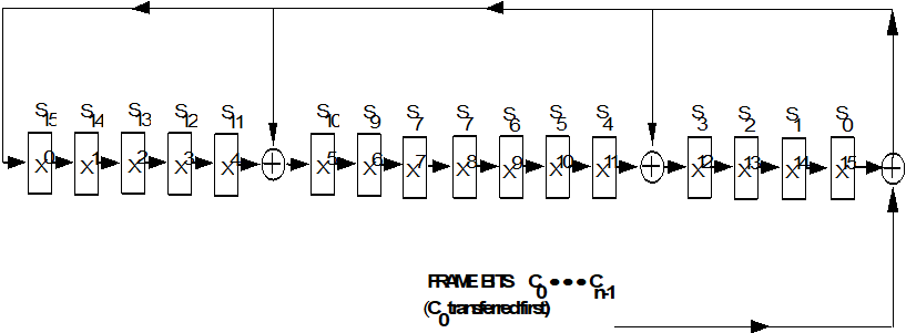 Figure: Decoder
ANNEX(informative)Changes from ESA-PSS-04-106
General
This annex describes some of the technical differences between this Standard and ESAPSS-04-106, ESA Packet Telemetry Standard, Issue 1, January 1988.
The main purpose of the annex is to assist in verifying the compatibility of existing systems.
The list of differences in this annex provides an indication of the differences in technical content between this Standard and ESAPSS-04-106. However, it is not the purpose of this annex to provide a complete list or to provide full details on each item in the list nor to describe the consequences of each item in the list. Refer to the relevant clauses of this Standard and to the PSS documents for further details.
ESAPSS-04-106 has a wider scope than this Standard. This annex only includes differences that are within the scope of this Standard.
Technical changes
In this Standard, packets with any Packet Version Number can be transferred as packets over the telemetry space data link, as long as their Packet Version Number is defined by CCSDS in CCSDS 135.0-B-3. This includes packets that are not included in ESAPSS-04-106.
ESAPSS-04-106 specifies the following Telemetry Transfer Frame lengths:
892, 1115 or 1784 octets if Reed-Solomon coding is used, or
any number of octets between 128 and 2040 if Reed-Solomon coding is not used.
This Standard specifies a maximum frame length of 2048 octets and that the length is consistent with the specifications contained in the standard for telemetry channel coding, ECSS-E-ST-50-01.
In ESAPSS-04-106, the Telemetry Transfer Frame length is fixed for the duration of the mission.
This Standard specifies that the length is constant for a mission phase.
In this Standard, a physical channel can have multiple master channels. Each master channel has a different value in the Spacecraft Identifier field of its frames.
ESAPSS-04-106 makes no distinction between a physical channel and a master channel.
In ESAPSS-04-106, if the Operational Control Field is used, then it is in every frame of the physical channel.
In this Standard, Operational Control Field use can be related to a master channel or to virtual channel(s).
The master channel and physical channel are less clearly distinguished in ESAPSS-04-106 than in this Standard.
In ESAPSS-04-106, if the Transfer Frame Secondary Header is used, then it is in every frame of the physical channel.
In this Standard, Transfer Frame Secondary Header use can be related to a master channel or to virtual channels. Similarly, in this Standard, if the Transfer Frame Secondary Header is used for an Extended Virtual Channel Frame Count, this use can be related to a master channel or to virtual channels.
ESAPSS-04-106 only defines one length (32 bits) for the Transfer Frame Secondary Header.
In this Standard other lengths from 16 to 512 bits can be used.
An Operational Control Field with Type Flag (bit 0) set to 1 is a Type-2 report. In ESAPSS-04-106 all use of Type-2 reports is reserved for future application.
In this Standard, Type-2 reports are defined as follows:
if bit 1 of the Operational Control Field is ‘0’, the contents of the report are project-specific;
if bit 1 of the Operational Control Field is ‘1’, the contents of the report are reserved for future application.
In this Standard, if the Synchronization Flag in a Telemetry Transfer Frame is set to ‘1’, the First Header Pointer is undefined.
ESAPSS-04-106 states that in this case the First Header Pointer is set to all “1”.
The differences in the names of fields and of groups of fields in a Telemetry Transfer Frame are shown in Table B-1.
Table: Differences in names from ESAPSS-04-106 for fields in a Telemetry Transfer Frame
|
Name in ESA-PSS-04-106
|
Name in this Standard
|
|
Frame Identification
|
(not used)
|
|
(not used)
|
Master Channel Identifier
|
|
Version Number
|
Transfer Frame Version Number
|
|
Frame Data Field Status
|
Transfer Frame Data Field Status
|
|
Secondary Header Flag
|
Transfer Frame Secondary Header Flag
|
|
Secondary Header Identification
|
Transfer Frame Secondary Header Identification
|
|
Secondary Header Version Number
|
Transfer Frame Secondary Header Version Number
|
|
Secondary Header Data
|
Transfer Frame Secondary Header Data
|
|
Secondary Header Length
|
Transfer Frame Secondary Header Length
|
|
Frame Error Control Word
|
Frame Error Control Field
|
ANNEX(informative)Differences from CCSDS recommendations
General
This annex describes the technical differences between this Standard and the related CCSDS recommendations defined in CCSDS 132.0-B-1.
This annex lists the differences of technical content between this Standard and the CCSDS recommendations indicated. However, it is not the purpose of this annex to provide complete details on each item in the list or to describe the consequences of each item in the list. Refer to the relevant clauses of this Standard and to the CCSDS recommendations for further details.
The given CCSDS recommendations have a wider scope than this Standard. This annex only includes the differences that are within the scope of this Standard.
Differences
This Standard defines the use of the Transfer Frame Secondary Header for extending the Virtual Channel Frame Count.
The extended count is not specified in the CCSDS recommendations.
In CCSDS 132.0-B-1, a telemetry transfer frame with its First Header Pointer set to ‘11111111110’ is called an OID Transfer Frame, meaning that it has Only Idle Data in its Transfer Frame Data Field.
In this Standard the term OID Transfer Frame is not used but the meaning of the First Header Pointer value is the same.
ANNEX(informative) configuration parameters
General
This annex provides a summary of the mission configuration parameters within the scope of this Standard.
This annex lists the options and values that can be taken by the parameters as specified in this Standard. designers are responsible for verifying the availability of support for the options and values selected for their mission.
Parameters of a physical channel
Overview
This subclause describes the mission configuration parameters of a physical channel that carries TM Transfer Frames.
Length of the TM Transfer Frame
The length of the TM Transfer Frame is an integer number of octets, up to 2048 octets. The length can be limited by the channel coding schemes specified in ECSS-E-ST-50-01.
The length is constant throughout a mission phase. The length is a configuration parameter for each mission phase.
Transfer Frame Version Number
The Transfer Frame Version Number is a mission configuration parameter.
For the TM Transfer Frames specified in this Standard it is set to ‘00’, indicating a version-1 transfer frame. The value is constant for all frames of the physical channel. The value applies to all master channels and all virtual channels of the physical channel.
For a physical channel where the frames have any other value in the Transfer Frame Version Number is not within the scope of this Standard.
Spacecraft Identifiers
A physical channel uses one or more integer values for the Spacecraft Identifier field of the TM Transfer Frames.
Each Spacecraft Identifier value corresponds to a specific master channel.
The list of Spacecraft Identifier values is a mission configuration parameter. See also NOTE 1 of requirement 5.2.2.3c.
Frame Error Control Field
If the physical link uses Reed-Solomon encoding, the presence of the Frame Error Control Field is optional. Otherwise, the field is present in all frames.
The presence or absence of the Frame Error Control Field is constant for all frames throughout a mission phase. It is a configuration parameter for each mission phase.
Handling of frames containing detected errors
The handling of TM Transfer Frames containing detected errors is mission dependent and is specified for each mission or mission phase.
Faulty frames can be delivered or discarded.
Multiplexing parameters
Issues concerning the multiplexing of master channels onto a physical channel, and the multiplexing of virtual channels onto a master channel, are not within the scope of this Standard.
Algorithms, priorities and other related parameters are mission dependent.
Pattern of idle data
For a Transfer Frame Data Field containing only idle data, as specified in requirement 5.4.3.4f, this Standard does not specify the pattern of the idle data.
The pattern of the idle data is a mission configuration parameter.
Parameters of a master channel
Overview
This clause describes the mission configuration parameters for a master channel.
Spacecraft Identifier
A master channel has a specific value for the Spacecraft Identifier field of the TM Transfer Frame. The Transfer Frame Version Number for the master channel is described in D.2.3 above.
Virtual Channel Identifiers
A master channel consists of between one and eight virtual channels. Therefore, a master channel uses up to eight integer values for the Virtual Channel Identifier field of the TM Transfer Frames. The values are mission configuration parameters. Each Virtual Channel Identifier value corresponds to a distinct virtual channel of the master channel.
Transfer Frame Secondary Header
The presence and use of the Transfer Frame Secondary Header is a mission configuration parameter for each mission phase. If the Transfer Frame Secondary Header is associated with a master channel in a mission phase, then the following apply:
The length of the Transfer Frame Secondary Header is a mission configuration parameter of the master channel for the mission phase.
The values of the Transfer Frame Secondary Header Flag and the Transfer Frame Secondary Header Length are constant for the mission phase in all frames of the master channel.
The application of the Transfer Frame Secondary Header is a mission configuration parameter of the master channel for the mission phase. The Transfer Frame Secondary Header can optionally be used for the extended virtual channel frame count specified in clause 5.3.4.
If the Transfer Frame Secondary Header is associated with a master channel, then the Transfer Frame Secondary Header cannot at the same time be associated with any of the virtual channels of the master channel.
Operational Control Field
The presence of the Operational Control Field is a mission configuration parameter for each mission phase. If the Operational Control Field is associated with a master channel in a mission phase, then the value of the Operational Control Field Flag is a mission configuration parameter of the master channel for the mission phase.
If the Operational Control Field is associated with a master channel, then the Operational Control Field cannot at the same time be associated with any of the virtual channels of the master channel.
Parameters of a virtual channel
Overview
This clause describes the mission configuration parameters of a virtual channel.
Spacecraft Identifier and Virtual Channel Identifier
A virtual channel has specific values for the Spacecraft Identifier and the Virtual Channel Identifier of the TM Transfer Frame. The Transfer Frame Version Number for the virtual channel is described in D.2.3 above.
Transfer Frame Secondary Header
The presence and use of the Transfer Frame Secondary Header is a mission configuration parameter for each mission phase. If the Transfer Frame Secondary Header is associated with a virtual channel in a mission phase, then:
The length of the Transfer Frame Secondary Header is a mission configuration parameter of the virtual channel for the mission phase.
The values of the Transfer Frame Secondary Header Flag and of the Transfer Frame Secondary Header Length are constant for the mission phase in all frames of the virtual channel.
The application of the Transfer Frame Secondary Header is a mission configuration parameter of the virtual channel for the mission phase. The Transfer Frame Secondary Header can optionally be used for the extended virtual channel frame count specified in clause 5.3.4.
Synchronization Flag
Setting the Synchronization Flag is a mission configuration parameter for a virtual channel. The value of the flag is constant for a mission phase in all frames of the virtual channel. The flag indicates the formatting of the Transfer Frame Data Field.
When the Synchronization Flag is ‘0’, then the Transfer Frame Data Field carries packets as specified in clause 5.4.3. The additional mission configuration parameters in this case are described in D.5.
When the Synchronization Flag is ‘1’, this Standard does not specify the contents of the Transfer Frame Data Field. The use and formatting of the field in this case are mission configuration parameters for the virtual channel.
Clause 5.4.4 describes the optional use of the field to carry asynchronously inserted data.
Operational Control Field
The presence of the Operational Control Field is a mission configuration parameter for each mission phase. If the Operational Control Field is associated with a virtual channel in a mission phase, then the value of the Operational Control Field Flag is a mission configuration parameter for the virtual channel for the mission phase.
Additional parameters when Synchronization Flag is ‘0’
Overview
This clause describes the additional mission configuration parameters for a virtual channel that has the Synchronization Flag set to ‘0’. The additional parameters concern the packets carried in the Transfer Frame Data Field.
Valid packet version numbers
The list of valid values for the Packet Version Number is a mission configuration parameter for the virtual channel.
Maximum packet length
The maximum packet length is a mission configuration parameter for the virtual channel.
Handling of incomplete packets
The handling of incomplete packets at the receiving end is a mission configuration parameter. Incomplete packets can be delivered or discarded.
Bibliography
|
ECSS-S-ST-00
|
ECSS system – Description, implementation and general requirements
|
|
ECSS-E-ST-50
|
Space engineering – Communications
|
|
ECSS-E-HB-50
|
Space engineering – Communication guidelines
|
|
CCSDS 132.0-B-1
|
TM Space Data Link Protocol – Blue Book, Issue 1, September 2003
|
|
CCSDS 320.0-B-4
|
CCSDS Global Spacecraft Identification Field Code Assignment Control Procedures – Blue Book, Issue 4, January 2006
|
|
CCSDS 350.0-G-2
|
The Application of CCSDS Protocols to Secure Systems – Green Book, Issue 2, January 2006
|
|
ESA-PSS-04-106
|
ESA Packet Telemetry Standard, Issue 1, January 1988
|