
Space engineering
Exchange of thermal analysis data
Foreword
This Standard is one of the series of ECSS Standards intended to be applied together for the management, engineering and product assurance in space projects and applications. ECSS is a cooperative effort of the European Space Agency, national space agencies and European industry associations for the purpose of developing and maintaining common standards. Requirements in this Standard are defined in terms of what shall be accomplished, rather than in terms of how to organize and perform the necessary work. This allows existing organizational structures and methods to be applied where they are effective, and for the structures and methods to evolve as necessary without rewriting the standards.
This Standard has been prepared by the ECSS-E-ST-31-04C Working Group, reviewed by the ECSS Executive Secretariat and approved by the ECSS Technical Authority.
Disclaimer
ECSS does not provide any warranty whatsoever, whether expressed, implied, or statutory, including, but not limited to, any warranty of merchantability or fitness for a particular purpose or any warranty that the contents of the item are error-free. In no respect shall ECSS incur any liability for any damages, including, but not limited to, direct, indirect, special, or consequential damages arising out of, resulting from, or in any way connected to the use of this Standard, whether or not based upon warranty, business agreement, tort, or otherwise; whether or not injury was sustained by persons or property or otherwise; and whether or not loss was sustained from, or arose out of, the results of, the item, or any services that may be provided by ECSS.
Published by: ESA Requirements and Standards Division ESTEC, P.O. Box 299, 2200 AG Noordwijk The NetherlandsCopyright: 2018© by the European Space Agency for the members of ECSS## Change log
|
ECSS-E-ST-31-04C
|
First issue
|
Introduction
The space industry is a domain in which complex products are developed and operated by (usually large) international teams. Analysis and testing are essential activities within the engineering process across all disciplines and thermal control is no exception.
It is not usually possible for the many partners in the industrial teams to standardise on the same tools for thermal analysis and test or operations results data processing. Nor is it desirable to do so for a number of reasons:
each partner should have the possibility to optimise their own processes;
different tools may be more appropriate at different levels of the supply chain;
healthy competition between the tool vendors promotes improvement and innovation at an affordable cost.
It is evident though, that for this philosophy to work, there is a need for easy and reliable data exchange.
An open standard that specifies an adequate neutral data format is the only viable way to realize reliable and cost effective data exchange and data sharing for the thermal analysts in the space industry. The STEP-TAS protocol provides this.
Scope
The requirements in this standard address the use of the STEP-TAS protocol for the exchange of thermal analysis data for space applications.
The intended audience for the requirements contained in this document is the developers of space thermal analysis software. The overview of STEP-TAS provided in clause 4 can also be of more interest general to a wider audience.
The requirements contained within this standard do not address the end users of the space thermal analysis tools – namely thermal engineers and thermal analysts. The rationale for this decision is that the primary applicable document for space thermal engineers (working on European projects) is the thermal control standard ECSS-E-ST-31. As such the best location for requirements addressing thermal engineers and analysts is the top level standard ECSS-E-ST-31.
This standard may be tailored for the specific characteristic and constrains of a space project in conformance with ECSS-S-ST-00.
Normative references
The following normative documents contain provisions which, through reference in this text, constitute provisions of this ECSS Standard. For dated references, subsequent amendments to, or revision of any of these publications do not apply. However, parties to agreements based on this ECSS Standard are encouraged to investigate the possibility of applying the more recent editions of the normative documents indicated below. For undated references, the latest edition of the publication referred to applies.
|
ECSS-S-ST-00-01
|
ECSS system - Glossary of terms
|
|
ECSS-E-ST-31
|
Space engineering - Thermal control general requirements
|
|
ECSS-E-ST-40
|
Space engineering - Software
|
|
ISO 10303-11 (2014)
|
Industrial automation systems and integration – Product data representation and exchange – Part 11: The EXPRESS language reference manual (second edition, 2004)
|
|
ISO 10303-21 (2002)
|
Industrial automation systems and integration – Product data representation and exchange – Part 21: Implementation methods: Clear text encoding of the exchange structure (second edition, 2002)
|
Terms, definitions and abbreviated terms
Terms from other standards
For the purpose of this Standard, the terms and definitions from ECSS-S-ST-00-01 apply.
For the purpose of this Standard, the terms and definitions from ECSS-E-ST-31 apply, in particular for the following terms:
geometrical mathematical model
thermal mathematical model
For the purpose of this Standard, the terms and definitions from ECSS-E-ST-40 apply, in particular for the following terms:
software component
Terms specific to the present standard
data exchange
process of transforming an exchange structure represented in a source format into equivalent data expressed in a different target format.
This can be a multi-stage process transforming from source format to a working data structure in memory and then to the target format.
dataset
<CONTEXT: STEP-TAS>
coherent and valid population conforming to the STEP-TAS schema (Annex A)
exchange structure
computer-interpretable format used for storing, accessing, transferring, and archiving data.
This term is adopted from [ISO 10303]
interface
<CONTEXT: STEP-TAS>
reader or writer
population
set of STEP-TAS entities
A STEP-TAS dataset is an example of a population.
reader
<CONTEXT: STEP-TAS>
software component which takes a STEP-TAS dataset as input, implements a data exchange process and generates a target format.
source format
input to a data exchange process
The data can be in a file on disk or in memory
target format
output of a data exchange process
valid population
a population that has been successfully passed a validation
validation
process of checking that all algorithmic constraints are satisfied
In the terminology of [ISO 10303] and STEP-TAS these algorithmic constraints are called “WHERE rules”.
writer
<CONTEXT: STEP-TAS>
software component which takes a source format as input, implements a data exchange process and generates a STEP-TAS dataset.
Abbreviated terms
The following abbreviations are defined and used within this standard:
|
Abbreviation
|
Meaning
|
|
AP
|
application protocol
|
|
API
|
application programming interface
|
|
CAD
|
computer aided design
|
|
CC
|
conformance class
|
|
CPU
|
central processing unit
|
|
GMM
|
geometrical mathematical model
|
|
ISO
|
International Organization for Standardization
|
|
MGM
|
meshed geometric model
|
|
NRF
|
network-model and results format
|
|
SDK
|
software development kit
|
|
SKM
|
space kinematic model
|
|
SMA
|
space mission aspects
|
|
STEP
|
standard for the exchange of product data
|
|
TAS
|
thermal analysis for space
|
|
TMM
|
thermal mathematical model
|
|
UML
|
unified modelling language
|
Nomenclature
The following nomenclature applies throughout this document:
The word “shall” is used in this Standard to express requirements. All the requirements are expressed with the word “shall”.
The word “should” is used in this Standard to express recommendations. All the recommendations are expressed with the word “should”.
It is expected that, during tailoring, recommendations in this document are either converted into requirements or tailored out.
The words “may” and “need not” are used in this Standard to express positive and negative permissions, respectively. All the positive permissions are expressed with the word “may”. All the negative permissions are expressed with the words “need not”.
The word “can” is used in this Standard to express capabilities or possibilities, and therefore, if not accompanied by one of the previous words, it implies descriptive text.
In ECSS “may” and “can” have completely different meanings: “may” is normative (permission), and “can” is descriptive.
The present and past tenses are used in this Standard to express statements of fact, and therefore they imply descriptive text.
Overview of STEP-TAS
Introduction
STEP-TAS is a protocol for the exchange (or sharing) of data between parties working in the domain of space thermal control engineering, over the whole life cycle of space products. In particular this data includes:
thermal analysis models, both Geometrical Mathematical Models (GMM) and Thermal Mathematical Models (TMM),
thermal analysis results (e.g. temperatures, nodal properties, heat flows),
test data such as acquired temperature, electrical voltage or current, or S/C telemetry,
operational data such as S/C telemetry or ground station parameters pertinent for thermal control engineers.
This document provides only a brief overview of the capabilities of STEP-TAS. For the interested reader, a thorough discussion of STEP-TAS is given in Annex C.
The underlying technology upon which STEP-TAS is built is the ISO Standard for the Exchange of Product model data [ISO 10303]. STEP can be used to represent product data across a wide range of disciplines by means of dedicated “Application Protocols” (APs). The best known AP is AP203 “Configuration controlled 3D designs of mechanical parts and assemblies,” which is the STEP format widely used for the exchange of CAD data.
The STEP standard uses a formal data modelling language called EXPRESS [ISO 10303-11] to define data structures together with structural constraints and algorithmic rules. The full STEP-TAS protocol, containing EXPRESS definition of entities and human readable annotation, is provided in Annex C.
Modular breakdown of the STEP-TAS protocol
The STEP-TAS protocol is composed of the following four modules, each one extending the previous one:
Network-model and results format (NRF) module,
Meshed geometric model (MGM) module,
Space kinematic model (SKM) module,
Space mission aspects (SMA) module.
Each of these modules is kept as generic as possible, so in the protocol itself no thermal control concepts are introduced. This opens the possibility of reuse of the modules by other disciplines (e.g. space environment and effects).
In order to introduce the essential thermal control concepts used by STEP-TAS, the core protocol described in the standard is complemented by a run-time loadable dictionary. The dictionary contains a collection of pre-defined terms relevant for thermal control, such as the definition of a thermal node, a thermo-optical property or a linear conductor. A reference version of the dictionary can be downloaded from the URI provided in Annex B and is also supplied with the software tools.
The term run-time means that software tools implementing a STEP-TAS interface can create and initialize a new dataset with a known set of entities read from the dictionary.
A UML package diagram showing composition of the full STEP-TAS protocol is shown in Figure 41.
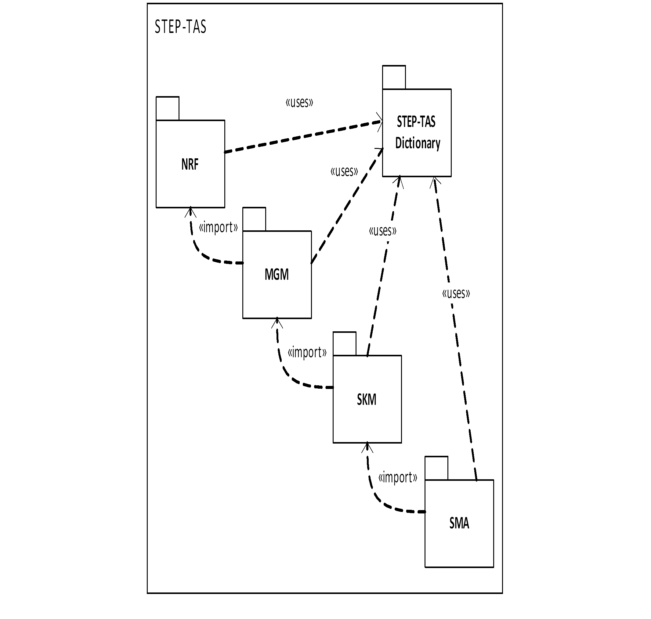 Figure 41: Informal UML Package Diagram showing STEP-TAS Dependencies
Each of the modules shown in Figure 41 is further broken down into sub-modules which contain the data entities. The following list summarises the contents of each module, with a full listing given in Annex C.
“Network-model and results format” (NRF) – generic engineering discipline independent foundation module
identification and naming of objects,
dates, times, quantities and physical units,
network-model representation including hierarchical submodels,
parametrics (e.g. representation of TMM user logic),
analysis, simulation, test or operational cases with runs and results,
simple hierarchical product or system structure, referencing the network model,
materials and material properties.
“Meshed geometric model” (MGM) – for analysis purposes based on primitive mathematical shapes
thin shell with thermo-optical properties, bulk properties, notional thickness and face activity,
hierarchical modelling using compound shapes (composed of lower level shapes) or Boolean cutting operations,
correspondence between geometric faces and network model nodes,
presentation colours.
“Space Kinematic Module” (SKM) – rigid body kinematics specified on MGM meshed geometric model
kinematic joints between parent and a contained shape,
per joint up to six degrees of freedom,
optional end-stops for translation or rotation.
“Space Mission Aspects” (SMA) – aspects of a space mission relevant to thermal and space environment analysis
space mission analysis case,
space coordinate system and pointing directions in space,
orbital arcs, both keplerian or general ephemeris,
identification of celestial body,
space environment parameters (e.g. sun temperature, deep space temperature),
named events associated with orbital arc or mission time,
kinematic articulations using SKM.
End user perspective on STEP-TAS
An ideal data exchange format would allow a user of thermal analysis Tool X to export a numerical model and transfer it to a user of thermal analysis Tool Y, who imports it and is able to work with it as if it was a native model – that is to say, as if the model had been developed in Tool Y from the outset. However, in order to achieve this, the underlying methods used by the different tools must be very similar and the capabilities of the tools need to be comparable, otherwise there will inevitably be a loss of information.
This ideal data exchange scenario is almost impossible to achieve. The thermal analysis tools on the market today all use different approaches for geometrical modelling, especially concerning thermal conduction. Even if the geometrical part of thermal models could be fully exchanged, then other more abstract thermal modelling entities such as face-to-face and edge-to-edge contacts or ad-hoc conductors, supported by tools in different ways, must then be handled.
Therefore the development of STEP-TAS has not sought to provide an ideal data exchange format, but rather to the address the most common use case, namely; the delivery of a subsystem thermal numerical model for integration into the overall system numerical thermal model (or some comparable scenario). As such STEP-TAS splits the “geometric” (radiation) and “network” models into different modules, analogous to the classical GMM and TMM. This approach allows a thermal numerical model to be delivered constituting a geometrical thermal model for the purpose of an integrated radiative analysis, together with a thermal mathematical model with sufficient exposed parameters for the customer.
In this context an exposed parameter could be any model variable (e.g. a conductivity, heat load, heater set point, etc.) that the model recipient might wish to vary, for example for the purpose of tuning a numerical model to test data.
Conformance
The convention for STEP-based standards is to divide the provision of, or adherence to, different aspects of the protocol into Conformance Classes (CC). This allows tool vendors to clearly indicate which functionality they support, and likewise for end users to understand what is possible in a tool. The conformance classes for STEP-TAS are enumerated in Table 41.
Table 41: STEP-TAS Conformance Classes
|
Class
|
Description
|
Concerns
|
|
CC1
|
Thermal radiation and conduction model defined by shell geometry
|
GMM
|
|
CC2
|
CC1 plus kinematic model
|
GMM
|
|
CC3
|
CC1 plus constructive geometry
|
GMM
|
|
CC4
|
CC3 plus kinematic model
|
GMM
|
|
CC5
|
CC1 plus space mission aspects
|
GMM
|
|
CC6
|
CC4 plus space mission aspects
|
GMM
|
|
CC7
|
Results for thermal radiation and conduction model
|
GMM
|
|
CC8
|
Thermal lumped parameter model without user-defined logic
|
TMM
|
|
CC9
|
CC8 plus results
|
TMM
|
|
CC10
|
Thermal lumped parameter model with user-defined logic
|
TMM
|
|
CC11
|
CC10 plus results
|
TMM
|
|
CC12
|
Thermal test or operation numerical model with results
|
Results
|
It is important to note that there can be no partial compliance to a conformance class; a tool either conforms or it does not. Conformance to a particular class requires that all protocol elements defined as part of that class be supported. The STEP-TAS protocol Annex C contains a full listing of all entities corresponding to different conformance classes.
This strict view of conformance does, however, raise some problems. For example, a thermal radiative analysis tool that implements a STEP-TAS export capability for 7 of the 8 possible cutting solids would strictly fail to achieve CC3. Some additional level of conformance information is therefore required by end users in order to fully understand the capabilities of the STEP-TAS interfaces.
As a guiding principle, for STEP-TAS to be as useful as possible to end users, readers and writers are recommended to convert as much as possible. If converters fail at the first unsupported entity then end users quickly become frustrated. However, if the majority of the model can be converted with only a few omissions or simplifications, then this gives the user something to work with.
Typical STEP-TAS software architecture
Without going into exhaustive detail, it is useful to describe how the different software elements of STEP-TAS fit together, in particular the relationship between the STEP-TAS protocol and the interfaces in thermal analysis software tools that thermal engineers are familiar with. This is shown graphically in the component diagram in Figure 42.
It is worth noting that although this is the usual software architecture, it is by no means essential. A software developer can theoretically implement a STEP-TAS interface directly from inspection of the protocol and the part 21 format description.
It can be seen that the protocol is passed into a code generator tool which generate software libraries in high level languages.
Two different SDKs currently exist, one for C++ and one for Python. These are created using two completely different and independent tool chains.
The protocol library is then complemented by a hand coded support library which provides utility and convenience functions. Together the support library and protocol library form the STEP-TAS Software Development Kit (SDK) which is distributed to software tool developers to be used in their applications via calls to the STEP-TAS Application Programming Interface (API).
 Figure 42: Informal UML Component Diagram Showing STEP-TAS Software Architecture
Metadata
The STEP-TAS exchange structure contains two types of metadata. Firstly there is the metadata contained within the HEADER, in particular the FILE_NAME and FILE_DESCRIPTION sections.
Secondly there is the metadata contained within the DATA section of the STEP-TAS exchange structure (i.e. the dataset itself) which is specific to STEP-TAS, in particular:
NRF_PERSON
NRF_ORGANIZATION
NRF_ORGANIZATIONAL_ADDRESS
NRF_ORGANIZATIONAL_PROJECT
NRF_TOOL_OR_FACILTY
NRF_APPROVAL
NRF_SECURITY_CLASSIFICATION_LEVEL
The metadata contained within the data section is specific to the end user and the project that the dataset is generated for.
The metadata contained within the header and data sections of STEP-TAS files is essential to ensure the traceability of STEP-TAS files. As such it is important that these fields are completed with meaningful values. Much of this metadata can be automatically created by the STEP-TAS writer without intervention from the end user. However, some of the data, such as the project or the address, are provided by the end user, for example using the tool’s preferences or in a dialog at runtime.
Requirements
Datasets
STEP-TAS Datasets shall conform to the EXPRESS schema defined in the DRD in Annex A.
Diagnostics
Software tools that implement STEP-TAS interfaces shall provide diagnostic information in a form suitable for the end user.
Diagnostic information shall be summarised to avoid overloading the user with information.
For example if many of the same diagnostic messages are generated, it can be difficult for an end user to find another distinct message within them. Therefore grouping or summarising this information can be useful.
Validation
STEP-TAS writers shall validate generated datasets, both explicit entities from the protocol and runtime entities loaded from the dictionary.
This is typically achieved using a dedicated validation process run concurrently with, or directly after, the dataset generation.
STEP-TAS writers may provide the option to disable the validation of generated datasets.
Validation of datasets can take significant CPU time for large models. So for some use cases - typically in-house workflows where the user has confidence in the processes and tools - it can be efficient and appropriate to disable the validation. The disabling of the validation can also be useful for debugging.
STEP-TAS readers should validate the input datasets.
In theory if all STEP-TAS exporters are generating valid datasets then validation by readers is not strictly needed. However, the [ISO 10303-21] format of STEP-TAS is a plain text encoding and thus corruption or tampering is possible. Import validation is therefore considered to be best practice, but not essential.
If a STEP-TAS reader encounters an invalid entity in the input dataset, the reader shall not fail unless the resulting model is unrealisable in the target tool.
If a STEP-TAS reader encounters an invalid entity in the input dataset, the reader may:
- attempt to correct the entity;
- omit the entity. If a STEP-TAS reader encounters an invalid entity in the input dataset, the reader shall emit appropriate diagnostic messages.
Conformance
Software tools that implement STEP-TAS interfaces shall document the conformance classes reached.
The STEP-TAS conformance classes are enumerated in Table 41.
Software tools that implement STEP-TAS interfaces for GMMs shall provide a conformance table indicating, for each geometrical item, if it is supported by the interface, along with informative remarks where necessary.
A template for the conformance information is provided in Annex D.
If a feature of the source model has no direct equivalent in the target format the STEP-TAS interface should not terminate unconditionally.
If a feature of the source model has no direct equivalent in the target format the STEP-TAS interface should complete the conversion according to the following options:
- approximation of the unsupported feature, or
- omission of the unsupported features.
For example if the target format does not support sub-models then some workaround using modified entity numbering or naming is appropriate.
When model features are simplified as specified in requirement 5.4d, STEP-TAS interfaces shall emit appropriate diagnostic messages.
In situations where a primitive geometrical entity of the source model has no equivalent in the format of the target model, STEP-TAS interfaces shall:
- approximate the entity in the target model, or
- replace the entity by a dummy shape in the same location, or
- omit the unsupported shape.
- 1 For example in requirement 5.4f.1, a suitable approximation is a triangulated mesh.
- 2 For example in requirement 5.4f.2 a suitable dummy shape is a bounding box or bounding sphere of the unsupported entity.
In situations where a Boolean-difference geometrical entity of the source model has no equivalent in the format of the target model, STEP-TAS interfaces shall: - approximate the entity in the target model, or
- replace the Boolean surface by the uncut surface, or
- replace the entity by a dummy shape in the same location, or
- omit the unsupported shape.
- 1 For example in requirement 5.4g.1, a suitable approximation is a triangulated mesh.
- 2 For example in requirement 5.4g.2, a suitable dummy shape is a bounding box or bounding sphere of the unsupported entity.
When geometrical entities are simplified as specified in requirements 5.4f and 5.4g above, STEP-TAS interfaces shall emit appropriate diagnostic messages.
Metadata
Header section
STEP-TAS writers shall complete the originating_system field of the FILE_NAME entity with the name and version of the analysis tool.
STEP-TAS writers shall complete the preprocessor_version field of the FILE_NAME entity with the name and version of the STEP-TAS interface module.
In some cases this is the same as the originating_system field.
Data section
STEP-TAS writers shall provide the capability to complete the following entities with meaningful values:
- NRF_PERSON
- NRF_ORGANIZATION
- NRF_ORGANIZATIONAL_ADDRESS
- NRF_ORGANIZATIONAL_PROJECT
- NRF_TOOL_OR_FACILTY The NRF_TOOL_OR_FACILITY may be completed automatically using the same values as specified in 5.5.1.
ANNEX(normative)EXPRESS Schema for STEP-TAS Datasets - DRD
DRD identification
Requirement identification and source document
This DRD is called from ECSS-E-ST-31-04 requirement 5.1a.
The schema can be downloaded from the ECSS-E-ST-31-04 download page of the ECSS public website (www.ecss.nl).
file name:ecss-e-st-31-04-annex-a.zip
http://ecss.nl/wp-content/uploads/2018/01/ecss-e-st-31-04-annex-a.zip
To access the download page:
-
make sure you are a registered user of the ECSS website since your credentials will be required, then click on the link above
In case of problems do the following: -
Log-on to the website
-
From the home page orange banner "Standards" – "Active Standards" – "Active Engineering Standards" – ECSS-E-ST-31-04C
Purpose and objective
The STEP-TAS EXPRESS schema defines the data, structural constraints and algorithmic rules of all STEP-TAS entities. The schema is used, together with the STEP-TAS dictionary, to develop software for the exchange of space thermal analysis data.
Expected response
Scope and content
The STEP-TAS Dataset shall be encoded as a [ISO 10303‐21] file.
This dataset is more commonly known as a “Part 21” or ʺSTEP Physical Fileʺ format
Special remarks
None.
ANNEX(informative)STEP-TAS dictionary
The STEP-TAS dictionary is described in clause 4.2. The STEP-TAS dictionary is encoded as an [ISO 10303‐21] file and the most recent version can be downloaded from the ECSS-E-ST-31-04 download page of the ECSS public website (www.ecss.nl).
file name:ecss-e-st-31-04-annex-b.zip
http://ecss.nl/wp-content/uploads/2018/01/ecss-e-st-31-04-annex-b.zip
To access the download page:
-
make sure you are a registered user of the ECSS website since your credentials will be required, then click on the link above
In case of problems do the following: -
Log-on to the website
-
From the home page orange banner "Standards" – "Active Standards" – "Active Engineering Standards" – ECSS-E-ST-31-04C
ANNEX(informative)Human readable STEP-TAS protocol
The full STEP-TAS protocol can be downloaded from the ECSS-E-ST-31-04 download page of the ECSS public website (www.ecss.nl).
file name:ecss-e-st-31-04-annex-c.zip
http://ecss.nl/wp-content/uploads/2018/01/ecss-e-st-31-04-annex-c.zip
To access the download page:
-
make sure you are a registered user of the ECSS website since your credentials will be required, then click on the link above
In case of problems do the following: -
Log-on to the website
-
From the home page orange banner "Standards" – "Active Standards" – "Active Engineering Standards" – ECSS-E-ST-31-04C
ANNEX(informative)Conformance table template for GMM
General remarks
As discussed in 5.4b, for GMMs it is necessary for users to have a more granular view of the conformance of a given tool to the STEP-TAS protocol. In this informative annex some template tables are provided that can be used by tool developers to add this information to the documentation or STEP-TAS interface of the tool.
The view presented in this annex is focussed on STEP-TAS, however, it is possible that a given tool introduces shapes that are not supported in STEP-TAS. In these cases it is the responsibility of the tool developer to document these shapes and how they are handled in the STEP-TAS interfaces.
Primitive bounded surfaces
Primitive bounded surfaces are the basic building blocks of GMMs represented in STEP-TAS format. The following table lists all the possible types of surface. In the Import or Export column the term SUPPORTED or NOT SUPPORTED is provided. Informative remarks can be provided in the Remarks column, or a link to a more detailed discussion if needed.
For example, for a Disc a suitable remark can be “Imported as central axis and radius disc.”
Table: Conformance table for primitive bounded surfaces
|
Shape
|
Import
|
Export
|
Remarks
|
|
Triangle
|
|
|
|
|
Rectangle
|
|
|
|
|
Quadrilateral
|
|
|
|
|
Disc
|
|
|
|
|
Cylinder
|
|
|
|
|
Cone
|
|
|
|
|
Sphere
|
|
|
|
|
Paraboloid
|
|
|
|
All of these shapes are inherited from a common parent and therefore all shapes have a common set of attributes that can set applied to them. A full listing is given in Annex C and Table D-2 provides the most critical attributes. In the Import or Export column the term SUPPORTED or NOT SUPPORTED is provided. Informative remarks can be provided in the Remarks column, or a link to a more detailed discussion if needed.
Many of these attributes are the subject of formal WHERE rules that validate the integrity of the entity. However this list is proposed in order for tool developers to provide additional useful information.
Examples of appropriate remarks might be highlighting interfaces that do not import/export bulk properties or thickness, tools that have different surface activity from STEP-TAS or tools that do not support meshing of shapes.
Table: Common attributes for primitive surfaces
|
Shape
|
Import
|
Export
|
Remarks
|
|
Activity
|
|
|
|
|
Notional thickness
|
|
|
|
|
Surface material
|
|
|
|
|
Bulk material
|
|
|
|
|
Colour
|
|
|
|
|
Meshing
|
|
|
|
Cutting solids
The representation of constructive geometry in STEP-TAS uses cutting solids to remove part of primitive surfaces or collections of primitive surfaces (so called compound meshed geometric items). The support for this type of constructive geometry varies from tool to tool.
The following table lists all of the cutting solids available in STEP-TAS. In the Import or Export column one of the terms: NOT SUPPORTED, INSIDE, OUTSIDE or BOTH is provided. These terms indicate the support for the shape in general and also the supported cutting sense for the Boolean operation. Informative remarks can be provided in the Remarks column, or a link to a more detailed discussion if needed.
A thorough discussion of the Boolean operations is provided in the STEP-TAS protocol Annex C.
Table: Conformance table for cutting solids
|
Shape
|
Import
|
Export
|
Remarks
|
|
Infinite plane
|
|
|
|
|
Infinite cylinder
|
|
|
|
|
Cylinder
|
|
|
|
|
Cone
|
|
|
|
|
Sphere
|
|
|
|
|
Paraboloid
|
|
|
|
|
Box
|
|
|
|
|
Triangular prism
|
|
|
|
Bibliography
|
ISO 10303 (2012)
|
Industrial automation systems and integration - Product data representation and exchange (November 2012)
|
|
UML
|
Unified Modeling Language, version 2.5, OMG, http://www.uml.org, (March 2015)
|