
Space product assurance
Welding of metallic materials for flight hardware
Foreword
This Standard is one of the series of ECSS Standards intended to be applied together for the management, engineering and product assurance in space projects and applications. ECSS is a cooperative effort of the European Space Agency, national space agencies and European industry associations for the purpose of developing and maintaining common standards. Requirements in this Standard are defined in terms of what shall be accomplished, rather than in terms of how to organize and perform the necessary work. This allows existing organizational structures and methods to be applied where they are effective, and for the structures and methods to evolve as necessary without rewriting the standards.
This Standard has been prepared by the ECSS-Q-ST-70-39C Working Group, reviewed by the ECSS Executive Secretariat and approved by the ECSS Technical Authority.
With permission of ISO this Standard contains in clause 10.4 extracts from ISO 25239-5:2011.
With permission of DIN this Standards contains in clause 10.2 reproductions based on DIN 29595:2007-04 Table 1 "Limits for external imperfections – Quality levels". Reproduction of this table was granted by DIN.
Disclaimer
ECSS does not provide any warranty whatsoever, whether expressed, implied, or statutory, including, but not limited to, any warranty of merchantability or fitness for a particular purpose or any warranty that the contents of the item are error-free. In no respect shall ECSS incur any liability for any damages, including, but not limited to, direct, indirect, special, or consequential damages arising out of, resulting from, or in any way connected to the use of this Standard, whether or not based upon warranty, business agreement, tort, or otherwise; whether or not injury was sustained by persons or property or otherwise; and whether or not loss was sustained from, or arose out of, the results of, the item, or any services that may be provided by ECSS.
Published by: ESA Requirements and Standards Division ESTEC, P.O. Box 299, 2200 AG Noordwijk The NetherlandsCopyright: 2015© by the European Space Agency for the members of ECSS## Change log
|
ECSS-Q-ST-70-39C
|
First issue
|
Scope
This Standard specifies the processing and quality assurance requirements for the different types of metallic welding (manual, automatic, semi-automatic and machine) for space flight applications. This standard can also be used for weld activities on space related ground equipment and development models for flight hardware. The Standard covers all welding processes used for joining metallic materials for space applications. This includes, but is not limited to:
Gas Tungsten Arc Welding (GTAW) / Tungsten Inert Gas (TIG), (process 14)
Gas Metal Arc Welding (GMAW) / Metal Inert Gas (MIG) (process 13)
Plasma Arc Welding (PAW) / Plasma of Transferred Arc (PTA), (process 15)
Electron beam welding (EBW), (process 51)
Laser beam welding (LBW), (process 52)
Friction Stir welding (process 43)
Magnetic Pulse welding (process 442)
Linear friction welding (process 42)
Rotary friction welding (process 42)
The specific process numbers mentioned above are listed according to the standard ISO 4063:2009.
This Standard does not detail the weld definition phase and welding pre-verification phase, including the derivation of design allowables.
This standard may be tailored for the specific characteristic and constraints of a space project in conformance with ECSS-S-ST-00.
Normative references
The following normative documents contain provisions which, through reference in this text, constitute provisions of this ECSS Standard. For dated references, subsequent amendments to, or revision of any of these publications do not apply. However, parties to agreements based on this ECSS Standard are encouraged to investigate the possibility of applying the more recent editions of the normative documents indicated below. For undated references, the latest edition of the publication referred to applies.
|
ECSS-S-ST-00-01
|
ECSS system – Glossary of terms
|
|
ECSS-E-ST-32-01
|
Space engineering –Fracture control
|
|
ECSS-M-ST-40
|
Space management – Configuration and information management
|
|
ECSS-Q-ST-10-09
|
Space product assurance – Nonconformance control system
|
|
ECSS-Q-ST-20
|
Space product assurance – Quality assurance
|
|
AMS 2644:2006
|
Inspection material, penetrant
|
|
ASTM E164-13:2013
|
Standard Practice for Contact Ultrasonic Testing of Weldments
|
|
ASTM E3:2007
|
Standard Guide for Preparation of Metallographic Specimens
|
|
ASTM E340:2013
|
Standard Test Method for Macroetching Metals and Alloys
|
|
ASTM E407:2007
|
Standard Practice for Microetching Metals and Alloys
|
|
AWS D18.2:2009
|
Guide to weld discoloration levels on inside of austenitic stainless steel tube
|
|
DIN 29595:2007-04
|
Fusion welded metallic components – requirements
|
|
DIN 65153:1997-06
|
Acceptance testing of plasma arc welding equipment.
|
|
EN 4179:2009
|
Aerospace series. Qualification and approval of personnel for non-destructive testing
|
|
EN 60974
|
Arc welding equipment
|
|
Part 1:2012
|
Welding power sources
|
|
Part 2:2013
|
Liquid cooling systems
|
|
Part 3:2013
|
Arc striking and stabilizing devices
|
|
Part 4:2010
|
Periodic inspection and testing
|
|
Part-5:2013
|
Wire feeders
|
|
Part 6:2010
|
Limited duty equipment
|
|
Part 7:2013
|
Torches
|
|
Part 8:2009
|
Gas consoles for welding and plasma cutting systems
|
|
Part 9: 2010
|
Installation and use
|
|
Part 10:2014
|
Electromagnetic compatibility (EMC) requirements
|
|
Part 11:2010
|
Electrode holders
|
|
Part 12:2011
|
Coupling devices for welding cables
|
|
Part 13:2011
|
Welding clamp
|
|
ISO 2553:2013
|
Welding and allied processes -- Symbolic representation on drawings -- Welded joints
|
|
ISO 3452
|
Non-destructive testing - Penetrant testing
|
|
Part 1:2013
|
General principles
|
|
Part 2:2013
|
Testing of penetrant materials
|
|
Part 3:2013
|
Reference test blocks
|
|
Part 4:1998
|
Equipment
|
|
Part 5: 2008
|
Penetrant testing at temperatures higher than 50 degrees C
|
|
Part 6:2008
|
Penetrant testing at temperatures lower than 10 degrees C
|
|
ISO 4063:2009
|
Welding and allied processes - Nomenclature of processes and reference numbers
|
|
ISO 4136:2012
|
Destructive tests on welds in metallic materials - Transverse tensile test
|
|
ISO 6848:2004
|
Arc welding and cutting - Nonconsumables tungsten electrodes - Classification
|
|
ISO 6947:2011
|
Welding and allied processes - Welding positions
|
|
ISO 9015
|
Destructive tests on welds in metallic materials - Hardness testing (Part 1 and 2)
|
|
Part 1:2001
|
Hardness test on arc welded joints
|
|
Part 2:2003
|
Microhardness testing of welded joints
|
|
EN 10204:2004
|
Metallic products - Types of inspection documents
|
|
ISO 11611:2007
|
Protective clothing for use in welding and allied processes
|
|
ISO 14731:2006
|
Welding coordination - Tasks and responsibilities
|
|
ISO 14732:2013
|
Welding personnel – Qualification testing of welding operators and weld setters for mechanized and automatic welding of metallic materials
|
|
ISO 14744
|
Acceptance inspection of electron beam welding machines
|
|
Part 1:2008
|
Principles and acceptance conditions
|
|
Part 2:2000
|
Measurement of accelerating voltage characteristics
|
|
Part 3:2000
|
Measurement of beam current characteristics
|
|
Part 4:2000
|
Measurement of welding speed
|
|
Part 5:2000
|
Measurement of run-out accuracy
|
|
Part 6:2000
|
Measurement of stability of spot position
|
|
ISO 15614-2:2005
|
Specification and qualification of welding procedures for metallic materials - Welding procedure test - Part 2: Arc welding of aluminium and its alloys
|
|
ISO 15616
|
Acceptance tests for CO2-laser beam machines for high quality welding and cutting
|
|
Part 1:2003
|
General principles, acceptance conditions
|
|
Part 2:2003
|
Measurement of static and dynamic accuracy
|
|
Part 3:2003
|
Calibration of instruments for measurement of gas flow and pressure
|
|
Part 4:2008
|
Acceptance tests for CO2-laser beam machines for high quality welding and cutting - Part 4: Machines with 2-D moving optics
|
|
ISO 17636:2013
|
Non-destructive testing of welds - Radiographic testing
|
|
Part 1:2013
|
X- and gamma-ray techniques with film
|
|
Part 2:2013
|
X- and gamma-ray techniques with digital detectors
|
|
EN-ISO 17637:2011
|
Non-destructive testing of welds - Visual testing of fusion-welded joints
|
|
ISO 17640:2010
|
Non-destructive testing of welds - Ultrasonic testing - Techniques, testing levels, and assessment
|
|
ISO 22826:2005
|
Destructive tests on welds in metallic materials - Hardness testing of narrow joints welded by laser and electron beam (Vickers and Knoop hardness tests)
|
|
ISO 22827:2005
|
Acceptance tests for Nd: YAG laser beam welding machines - Machines with optical fibre delivery
|
|
Part 1:2005
|
Laser assembly
|
|
Part 2:2005
|
Moving mechanism
|
|
ISO 24394:2008
|
Welding for aerospace applications - Qualification test for welders and welding operators - Fusion welding of metallic components
|
|
ISO 25239-3:2011
|
Friction stir welding - Aluminium - Part 3: Qualification of welding operators
|
|
ISO 25239-5:2011
|
Friction stir welding - Aluminium - Part 5: Quality and inspection requirements
|
Terms, definitions and abbreviated terms
Terms from other standards
For the purpose of this Standard, the terms and definitions from ECSS-S-ST-00-01 apply and in particular the following:
critical
For the purpose of this Standard, the terms and definitions from ECSS-E-ST-32-01 apply.
fail-safe
Terms specific to the present standard
acceptable weld
weld that has no defects and passes all acceptance criteria
all weld metal tensile test specimen
test specimen with the reduced section composed of only weld metal
alpha sample
weld sample produced prior to the start of a production run, used to verify selected aspects of the quality of the weld to be produced during production
The term "pre-weld sample" is synonymous.
base metal
part of the welded joint which remains un-melted or un-stirred for friction stir welding, and unaffected by the heat of the process, such that the microstructure and mechanical properties are unaffected
beta sample
weld sample produced at the end of a production run, used to verify selected aspects of the quality of the weld to be produced during production
The term "post-weld sample" is synonymous.
critical structure
structure or component, the single failure of which cause significant danger to personnel, loss of system, loss of major component, or loss of control, thus resulting in an operation penalty, or loss of the system, or abortion of the mission
defect
<CONTEXT: welding>
unacceptable feature of the weld
This term is defined in the present standard with a different meaning than in ECSS-S-ST-00-01. The term with the meaning defined herein is applicable only to the present standard.
delta verification
welding trials performed to extend the range of a previously approved WPS
design authority
responsible for the detailed design of the welded part in compliance to an approved specification and authorized to sign certificates of design or certified sealed drawings in accordance with procedures
engineering authority
contracting agency or corporate organisation that acts for and on behalf of the customer and responsible for the structural integrity or maintenance of airworthiness of the hardware and compliance with all business agreement documents
fabrication
structure manufactured by assembling various parts together
feature
geometric or microstructural non-uniformity in the weld or weld zone
filler metal
metal supplied in the form of a welding rod, sometimes flux coated, melted by a heat source into a joint between components to be joined
heat affected zone (HAZ)
portion of the base metal that was not melted during fusion welding or stirred during friction stir welding but whose microstructure and mechanical properties were altered by the heat applied during the welding process
hybrid welding
type of welding process that combines the principles of laser beam welding and arc welding
in process correction
see "re-weld"
job card
see "shop traveller"
machine welding
welding with equipment that performs the welding operation
maintenance book
record of maintenance performed on equipment including any modifications
manual welding
welding operation performed and controlled completely by hand
mission critical
item whose failure generates a significant operational impact by jeopardizing the ability to successfully complete the assigned mission.
This includes parts which have failure effects that adversely impact mission effectiveness.
non-critical structure
structure or component which is non-critical and is contained so that failure does not affect other flight elements or personnel
piece part
individual metallic parts to be welded
The term of "piece part" is commonly used in welding. Examples are: sheets, plates and extrusions.
post weld sample
see "beta sample"
process
<CONTEXT: welding>
material or joint type and dimension or welding process combination which is covered by a WPS
This term is defined in the present standard with a different meaning than in ECSS-S-ST-00-01. The term with the meaning defined herein is applicable only to the present standard.
production run
welding run corresponding to the same sample coupons, the same material lot and the same thermal treatment, pre- or post- batch as the flight or production hardware itself
re-acceptance
welding activities aimed to assure the obtaining of the previously verified and qualified results
repair welding
additional welding pass which is only allowed after the defective weld has resulted in an major NCR, and then only released by the welding supervisor
re-weld
additional weld pass according to a qualified weld procedure to eliminate defects
- 1 It is important to ensure traceability (for example in the shop traveller).
- 2 The term "in process correction" is synonymous.
router
see "shop traveller"
run on and run off tabs
piece of base metal which is tack welded onto the ends of the workpiece to allow the welder to start and end the weld without forming defects associated with the start and stop of the weld
shop traveller
document recording the complete welding process, including repair welds, malfunction of equipment, inspections, and reference of welded samples
Terms "job card" and "router" are synonymous.
thermomechanically affected zone (THAZ)
part of a friction stir weld which is affected by the movement of the mechanical tool and the application of heat
weldment
fabrication containing a weld
weld test record
results of tests conducted on the weld for the purpose of demonstrating process and procedural capability and repeatability
Demonstration of capability verifies the welding procedure.
welding verification test plan
document summarising the activities necessary to reach an approved WPS
Demonstration of capability verifies the welding procedure.
welder
person who performs manual welding
welding
joining process that produces a local coalescence of materials by heating, by applying pressure, or both
welding inspector
certified individual with the responsibility and ability to judge the quality of the welded specimens in relation to some form of written specification
welding operator
person who operates welding equipment that perform mechanised, machine welding
welding procedure specification (WPS)
document providing in detail the required variables for a specific application to ensure repeatability by certified welders and welding operators
The WPS is under the responsibility of the welding supervisor.
welding supervisor
person in charge of welding coordination and the WPS
Term "welding coordinator" is synonymous to the word "welding supervisor".
Abbreviated terms
For the purpose of this Standard, the abbreviated terms from ECSS-S-ST-00-01 and the following apply:
|
Abbreviation
|
Meaning
|
|
AC
|
alternating current
|
|
AVC
|
arc voltage control
|
|
CoC
|
certificate of conformance
|
|
DC
|
direct current
|
|
DRD
|
document requirements definition
|
|
EBW
|
electron beam welding
|
|
FSW
|
friction stir welding
|
|
GMAW
|
gas metal arc welding
|
|
GTAW
|
gas tungsten arc welding
|
|
HAZ
|
heat affected zone
|
|
LBW
|
laser beam welding
|
|
LFW
|
linear friction welding
|
|
MIG
|
metal inert gas (welding)
|
|
MPW
|
magnetic pulse welding
|
|
NCR
|
nonconformance report
|
|
NDI
|
non-destructive inspection
|
|
NDT
|
non-destructive test
|
|
ppm
|
parts per million ( 10 -6 )
|
|
QTP
|
qualification test plan
|
|
QTR
|
qualification test report
|
|
RFA
|
request for approval
|
|
SME
|
small, medium enterprise
|
|
TIG
|
tungsten inert gas (welding)
|
|
TMAZ
|
thermo mechanically affected zone
|
|
WPS
|
welding procedure specification
|
|
WPVR
|
welding procedure verification report
|
|
WVTP
|
welding verification test plan
|
|
WVTR
|
welding verification test report
|
Conventions
The term "qualification" from the ECSS-Q-ST-70-39 is synonymous with the term "verification" used in ECSS documentation. This not applicable to the qualification of personnel.The term "qualification test plan (QTP)" used in common welding documentation is synonymous with the term "welding verification test plan (WVTP)"from the ECSS-Q-ST-70-39. The term "qualification test report (QTR)" used in common welding documentation is synonymous with the term "welding verification test report (WVTR)" from the ECSS-Q-ST-70-39.### Nomenclature
Formal verbs
The following nomenclature applies throughout this document:The word "shall" is used in this document to express requirements. All the requirements are expressed with the word "shall".The word "should" is used in this document to express recommendations. All the recommendations are expressed with the word "should".:::note It is expected that, during tailoring, all the recommendations in this standard are either converted into requirements or tailored out. :::
The words "may" and "need not" are used in this document to express positive and negative permissions respectively. All the positive permissions are expressed with the word "may". All the negative permissions are expressed with the words "need not".The word "can" is used in this document to express capabilities or possibilities, and therefore, if not accompanied by one of the previous words, it implies descriptive text.:::note In ECSS "may" and "can" have a complete different meaning: "may" is normative (permission) and "can" is descriptive. :::
The present and past tense are used in this document to express statement of fact, and therefore they imply descriptive text.### Principles
General
The welding of metallic materials occurs frequently during the manufacture and assembly of parts for a space flight hardware. Although there are few standards which provide information on the welding of aerospace materials, there are subtle differences which can lead to some variability in the interpretation of weld acceptance criteria and the levels required for weld qualification.
This Standard specifies the necessary requirements to perform welding of metallic materials for space applications, and is comprised of the following clauses:
Welding Design
Welding and Test Personnel
Equipment and Facilities
Welding Procedure Specification (WPS)
Weld Inspection
Weld Acceptance Criteria
Welding Process Verification
Flight Hardware Production
Quality Assurance
Figure 41 identifies the steps to be taken in order to produce a verified process which can then be used to produce flight hardware.
All new welding processes that are not covered by ISO 4063:2009 are automatically considered as critical processes.
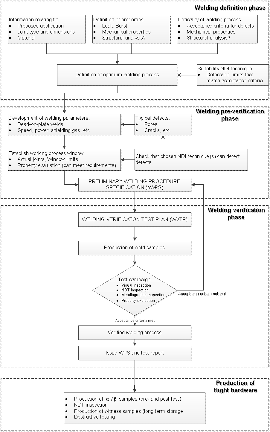 Figure 41 Flow chart showing the steps required to produce a verified weld process and flight hardware
Classification of weld safety classes
Overview
Welded joints for space applications are classified into three classes according to their function and requirements using safety categories and sensitivity levels.
Safety Class 1
Class 1 joints are considered critical and structural. Failure of a Class 1 joint results in a loss of spacecraft, major components, loss of life, or loss of control of the spacecraft. Class 1 joints have the highest level of scrutiny in terms of acceptance, which is appropriate to the criticality of performance including internal and external weld integrity verification.
Safety Class 2
Class 2 joints are non-critical but structural, their failure can reduce the efficiency of the system but not cause the loss of the spacecraft. Class 2 joints require weld integrity verification (either external, internal, or both) appropriate for the intended application.
Safety Class 3
Class 3 joints are non-critical and non-structural and are contained so that failure does not affect other flight elements. These joints require minimal weld integrity verification, the controls are mainly visual.
Weld sensitivity levels
Depending on the material and welding process, it is inevitable that some defects and features can be present in a welded joint. The acceptability of such defects or features differ by their nature and size and are assigned for the purpose of quality inspection to three acceptance levels (A, B or C) according to the compliance with the component requirement.
Level A represents the more stringent requirements, and level C the least stringent requirements and B is in between A and C.
Tailoring of the weld acceptance criteria
Verification of welded products takes into account the requirements and acceptance criteria of this standard. If they turn out to be insufficient (or too strict) tailoring can be necessary in agreement with the customer.
Welding design
Design of Welded Connections
The engineering authority together with the weld supervisor shall design the weldment.
The engineering authority together with the weld supervisor shall specify the welding requirements to ensure compliance with all system and mission requirements.
The engineering documentation shall have specification for welds of the following categories:
- Fracture critical and safe-life items,
- Durability critical,
- Mission critical, or
- Safety critical.
The engineering authority shall demonstrate that all design requirements are in compliance with the WPS from the DRD from Annex A.
The engineering authority together with the weld supervisor shall specify process controls for welding and demonstrate that all design requirements are met.
Examples of durability critical include fatigue, corrosion, creep.
Acceptable joints design
The acceptable joint design shall be in accordance with the requirements of ISO 2553:2013.
Welding and inspection personnel
Welding supervisor
The manufacturer shall employ a qualified and certified welding supervisor as the responsible and competent authority for welding.
The welding supervisor shall be qualified and certified as welding coordinator in accordance with ISO 14731:2006.
For companies that are not able to appoint a qualified and certificated welding supervisor, the following options shall be used:
- A certificated and qualified supervisor is appointed by the national welding institute of the country in which the welding company is located.
- A supervisor is trained and certified by the national welding institute of the country in which the welding company is located.
SMEs are examples of companies that are not usually able to appoint a welding supervisor.
Qualification and certification of welders and welding operators
Validity limits for operator qualification
Welder and welding operators shall pass the welder and welder operation qualification tests.
With completion of the welder and welder operation qualification tests a welder or welder operator shall obtain the certificate.
Welding operations on the welding equipment shall only be performed by welders and welding operators holding a valid qualification test certificate.
Valid period of a certificate for a welder and welder operation qualification tests shall be for a maximum period of two years from the date the qualification test results are issued.
Qualification of a process given to a welding operator may be extended indefinitely provided the three following conditions are met:
- a qualification record is maintained from the date of the initial qualification,
- regular audit of the records specified in the 6.2.1e.1 is performed,
- the welder and welding operator use the process within every six month period. The welders and welding operators shall be assigned by the responsible welding supervisor
Manual arc welding
Manual arc welding shall be performed by welders who have a valid qualification certificate in accordance with ISO 24394:2008.
Mechanised fusion and resistance welding
Mechanised fusion and resistance welding shall be performed by welding operators who have a valid certificate in accordance with ISO 14732:2013.
Mechanised friction stir welding
Mechanised friction stir welding shall be performed by welding operators who have a valid certificate in accordance with ISO 25239-3:2011.
Qualification and certification of welding inspectors
The personnel for welding inspection shall be assigned and briefed by the responsible qualified welding inspector.
The personnel for visual inspection shall be qualified and certified in accordance with EN 4179:2009.
Welding inspectors shall be qualified and certified in NDI in accordance with EN 4179:2009.
Clothing requirements
For welding processes the clothing shall specified by the welding supervisor, except the case specified in the requirement 6.4c
The protective clothing used for arc welding and allied processes shall be in accordance with ISO 11611:2007.
When welding in a clean room, only nitrile gloves shall be used by the welders, welding operators and all other personnel involved in the welding process.
When welding outside a clean room, the welders, welding operators and all other personnel involved in the welding process shall wear lint free clothing and lint free gloves for assembly and welding of a flight hardware.
Equipment and facilities
Qualification of the welding equipment
General requirements
The manufacturer of welded joints shall be audited by the welding supervisor to demonstrate that the workshop facilities and equipment are capable of performing the welding operation.
When no welding supervisor is available as specified in the requirement 7.1.1a, the materials and process engineer responsible for welding shall perform the audit.
The welding machines used for mechanized welding shall be subject to testing, inspection and maintenance in accordance with the requirements of the equipment manufacturer.
When the welding equipment manufacturer does not state a time period for the inspection and maintenance of the welding machines, specified in the requirement 7.1.1c, inspection and maintenance shall be performed every 12 months.
Specific requirements
Qualification of the welding equipment shall be performed in accordance with the requirements from the following standards:
- For Electron Beam welding from ISO 14744 (Part 1 to 6).
- For Laser Beam welding (CO2) from ISO 15616 (Part 1 to 4).
- For Laser Beam welding (Nd:YAG) from ISO 22827 (Part 1 and 2).
- For Plasma arc welding equipment from DIN 65153:1997-06.
- For Arc welding equipment from t EN 60974 (Part 1 to 13).
- For Friction Stir welding from clause 4.4 of ISO 25239-5:2011.
For the versions of the different parts of the referenced ISO and EN Standards see clause 2.
Maintenance and repair of the welding equipment
The weld equipment shall be monitored and maintained within a 12 months period.
Measurements and control for automatic, semi-automatic, and machine joining operations shall be initially calibrated and recalibrated every 12 months.
Examples of measurement and control instruments includes meters and gauges.
In case the requirement 7.2b cannot be applied, a maintenance plan shall be provided which demonstrates an alternative method.
When maintenance is performed to the instruments, specified in the requirement 7.2b, that can cause changes to calibration, a periodic recalibration shall be performed.
Re-acceptance of an equipment shall be performed in the following cases:
- after severe repair operation,
- after relocation of the welding equipment,
- after installation of electrical components which can affect any welding parameter.
The welding supervisor shall approve the re-acceptance of the welding equipment.
welding supervisor shall decide to perform a re-acceptance of the welding equipment or not.
All maintenance operations of welding equipment shall be documented.
For example, in the Maintenance Book.
Materials and consumables
Base materials
The base metal alloy shall be procured with an inspection certificate of type 3.1 from the requirements from clause 4.1 of EN 10204:2004.
This is a certificate issued by the manufacturer in which the manufacturer declares that the products supplied are in compliance with the requirements of the order made be the customer and in which the manufacturer supplies test results.
The base metal, material condition, and their appropriate specification shall be recorded as a part of the WPS from DRD from Annex A.
Weld start and runoff tabs, when used, shall be of the same alloy as the base metal alloy being joined.
Filler materials
The filler metal shall be procured with an inspection certificate of type 3.1 from the requirements from clause 4.1 of EN 10204:2004.
This is a certificate issued by the manufacturer in which the manufacturer declares that the products supplied are in compliance with the requirements of the order made be the customer and in which the manufacturer supplies test results.
The supplier shall demonstrate no contamination or condensation on the filler material.
For example storage in an oven +25 °C to +45 °C.
Shielding and backing gas
The shielding gases shall be procured with a lot specific CoC.
Purity levels of shielding gases shall be in conformance with the values from the Table 71.
The shielding gases for welding should be in conformance with Table 72.
Gases for plasma welding should be in conformance with Table 72.
Table 71: Acceptable gas purity levels
|
Name of the gas
|
Purity levels
|
Moisture
|
|
Argon
|
Ar: 99,999 % min
|
H2O < 2 ppm
|
|
Helium
|
He: 99,996 % min
|
H2O < 5 ppm
|
|
Nitrogen
|
N2: 99,999 % min
|
H2O < 5 ppm
|
Table 72: Recommended shielding gases for welding
|
Material
|
Gas Type
| |||||||
|
Ar
|
He
|
Ar-He
|
Ar-O
|
Ar-H
|
N
|
CO2
|
Ar-CO2
| |
|
Aluminium and alloys
|
A
|
A
|
A
|
|
|
|
|
|
|
Cobalt and its alloys
|
A
|
A
|
A
|
|
A
|
|
|
|
|
Copper and its alloys
|
A
|
A
|
A
|
|
|
|
|
|
|
Magnesium and its alloys
|
A
|
A
|
A
|
|
|
|
|
|
|
Nickel and its alloys
|
A
|
A
|
A
|
|
|
|
|
|
|
CRES alloys
|
A
|
A
|
A
|
A
|
|
[1]
|
|
|
|
Plain carbon steels
|
A
|
A
|
A
|
A
|
|
|
[2]
|
[2]
|
|
Low carbon steels
|
A
|
A
|
A
|
A
|
|
|
|
[2]
|
|
Titanium and its alloys
|
A
|
A
|
A
|
|
|
|
|
|
|
A = allowed gas, or gas mixture
| ||||||||
Tooling and fixtures
Materials for tooling and fixtures used in the joining operation shall not affect the welding arc or beam.
Materials for tooling and fixtures used in the joining operation shall not be detrimental to the weld quality.
Tooling and fixtures shall be cleaned prior to welding.
Tooling and fixtures shall not be a source of contamination to the joint.
For welding processes where degaussing is necessary, magnetic materials used for tooling shall be degaussed prior to welding.
Degaussing shall be specified in maintenance plan or WPS.
Tooling and fixtures shall demonstrate compliance with dimensions identified in the WVTP from DRD in Annex B and submit to approval by the customer.
Tooling material within 2 cm of the root of the weld shall be from the same alloy as the material being welded except the case specified in the requirement 7.3.4i.
Backing bar and fixation tool may be from a different material to that of the alloy being welded.
Justification to the deviations from the requirement 7.3.4h shall be provided in the WVTP and in the verification documentation.
Justification specified in the requirement 7.3.4j shall be approved by the customer during verification.
Welding procedure specification (WPS)
Requirements applicable to all processes
General
All welds shall be completed in conformance with the WPS specified in the DRD in the Annex A.
Drawings
Every drawing that shows a weld seam shall be in conformance with DRD in Annex A.
All information specified in the drawing from the requirement 8.1.2a shall be approved by the welding supervisor.
Features for all welds shall be specified either on the engineering drawing or in supporting documentation.
Welding process
All welding processes shall be in accordance with ISO 4063:2009.
Weld preparation
All joints shall be documented in the WPS from DRD from Annex A, design drawing, or other documents specified by the customer.
For multilayer welding, the complete weld run sequence shall be given on the engineering drawing.
The applicable welding position shall be in accordance with ISO 6947:2011.
Surface roughness shall be representative of the qualification.
The joint configuration shall be approved by the design authority.
The pre-weld joint fit-up shall be under the responsibility of the design authority.
For welding processes where degaussing is applicable, magnetic materials shall be degaussed prior to welding.
Cleanliness prior to welding
Prior to welding, a cleaning step shall be performed.
The description of the cleaning step shall be documented in the WPS.
Pre-weld cleaning of contaminants detrimental to weld quality on filler materials and surfaces to be welded shall be performed in an environment which cannot degrade the quality of the weld.
Contamination of filler materials shall be avoided.
All surfaces adjacent to welds shall be free of foreign material.
The surfaces specified in the requirement 8.1.5e should extend beyond the region of the HAZ.
Examples of foreign materials includes oxide, paint, grease, oil, dirt, organic residue.
When solvent cleaning does not remove contaminants, surfaces shall be cleaned using at least one of the following methods:
- Chemical cleaning,
- Electrochemical cleaning, and
- Mechanical cleaning.
After cleaning is performed in compliance with the requirements from 8.1.5g.1 to 8.1.5g.3, a further solvent cleaning step shall be performed.
The cleaning procedure shall indicate the maximum time authorized between the final cleaning and welding.
Tack welds
Tack welds shall be clean and free of cracks.
This is based on visual inspection.
When a filler metal is used for the intended application, the same filler metal shall be used to manufacture the tack welds.
All discolorations due to tack welding shall be removed prior to welding.
Tack welds shall be completely re-melted during welding so that they have no effect on the weld quality.
Backing and shielding gas
Backing and shielding gases shall be used in conformance with the requirements from DRD from Annex A.
Weld inspection
Non-destructive techniques
General
The production of weld joints and test joints shall be inspected to demonstrate that the construction, physical dimensions, identification, and production records are in conformance with the engineering drawing and the requirements from clause 9.
Fracture control shall be performed in conformance with requirements from ECSS-E-ST-32-01.
Fracture control can impose additional inspection requirements.
Visual and dimensional examination
Visual examination shall be performed in accordance with the requirements of EN-ISO 17637:2011.
The examination as required by 9.1.2a. may be replaced by a visual examination under following conditions:
- use of a x5 to x10 magnification with a maximum of twenty power magnification available to examine features,
- use of mirrors or endoscopes.
Visual and dimensional examination shall be performed in conformance with the weld acceptance criteria of clause 10.
During visual inspection, the following parameters shall be examined and documented: - General appearance and regularity,
- Excess weld metal,
- Undercuts and shrinkage groove,
- Craters, open pores or open cracks,
- Root concavity,
- Excessive penetration,
- Incomplete penetration,
- Burn-through,
- Weld spatter,
- Lack of fusion,
- Weld discolouration.
It is possible that not all parameters are accessible.
During dimensional examination, the following shall be measured and documented for class 1 parts:
- Linear and angular misalignment,
- Weld width and angle. Welded titanium joints shall be acceptable in the following cases:
- when the colour of the joint is equal or better than brown in conformance with the colours from the Table 91,
- discoloration is removed prior to additional welding,
- at least 25 μm thickness of material is removed.
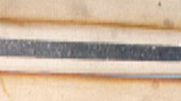
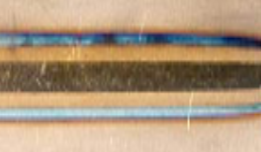
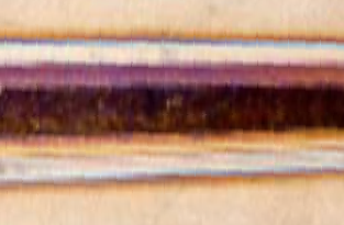
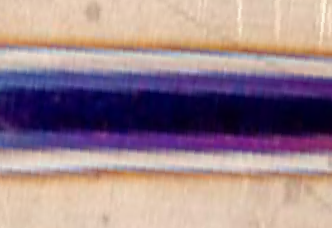
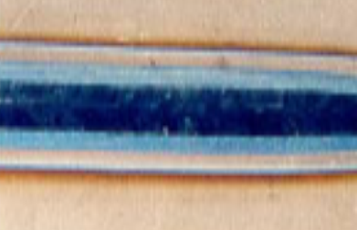
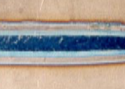
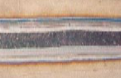
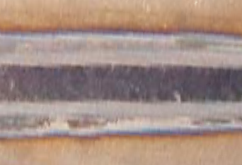
Examples of weld discoloration for titanium welds are shown in the Table 92.
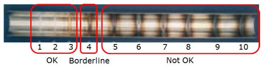
Welded austenitic stainless steel tube joints shall be acceptable when the colour of the inside of the joint is equal or better than level 4, shown in the Figure 91.
This is in conformance with the requirements of AWS D18.2:2009.
Table 91: Colour acceptance criteria for titanium fusion welds
|
Weld Colour
|
Quality Indication
|
|
Bright Silver
|
Acceptable
|
|
Silver
|
Acceptable
|
|
Light Straw
|
Acceptable
|
|
Dark Straw
|
Acceptable
|
|
Bronze
|
Acceptable
|
|
Brown
|
Acceptable
|
|
Violet
|
Unacceptable
|
|
Dark Blue
|
Unacceptable
|
|
Light Blue
|
Unacceptable
|
|
Green
|
Unacceptable
|
|
Grey
|
Unacceptable
|
|
White
|
Unacceptable
|
Table 92: Examples of weld discoloration for titanium fusion welds (for information only)
|
Silver
|
Dark Straw
|
|
|
|
|
Brown
|
Violet
|
|
|
|
|
Dark Blue
|
Light Blue
|
|
|
|
|
Grey
|
White
|
|
|
|
|
|
Figure 91: Discoloration of the inside of austenitic stainless steel tubes
Penetrant inspection
For detecting imperfections such as cracks and pores at the surface, the penetrant inspection shall be performed in accordance with ISO 3452 Part 1 to 6.
- 1 ISO 3452 is equivalent to EN 571-1:1997.
- 2 For the versions of the different parts of ISO 3452 see clause 2.
Penetrant inspection methodology shall be performed in conformance with the requirements of AMS 2644:2006.
QPL-SAE-AMS-2644-4 (1 October 2004) is a list qualified products for penetrants.
Fluorescent penetrant inspection for sensitivity level 3 or higher shall be performed.
Linear indications shall not be acceptable.
The acceptability of non-linear indications depends on the design requirements.
For the detection of other defects, and unless otherwise is specified by design, the penetrant inspection shall be performed in accordance with the criteria of acceptance requirements specified in the clause 10.
Radiographic testing
Radiographic examination shall be performed in accordance with the methodology requirements of ISO 17636-1:2013 and ISO 17636-2:2013.
This method is suitable to detect the following imperfections: cracks, internal pores, lack of fusion, penetration or foreign inclusions.
The welds shall be inspected in the perpendicular direction.
The radiographic testing shall be performed in accordance with the criteria of acceptance requirements specified in the requirements of clause 10.
Ultrasonic inspection
For materials thicker than 8 mm, ultrasonic inspection shall be performed in accordance with ISO 17640:2010.
For materials thinner than 8 mm, ultrasonic inspection shall be performed in accordance with ASTM E164-13:2013.
Depending on the design of the weld and sensitivity level required, ultrasonic inspection should be selected instead of radiographic testing.
The ultrasonic inspection shall be performed in accordance with the criteria of acceptance requirements specified in the requirements of clause 10.
X-ray tomography inspection (CT scan)
X-Ray tomography shall be applied when techniques such as radiographic or ultrasonic inspection are not sufficient to detect the internal defects.
In case when the additional inspection specified in the requirement 9.1.6a is adopted, it shall be included into the WPS from DRD in Annex A and WVTP from DRD in Annex B and welding VTR.
The X-ray tomography inspection shall be performed in accordance with the criteria of acceptance requirements specified in the requirements from clause 10.
Destructive testing
Metallographic measurement
When metallographic examinations are required for cross-section examination, samples shall be prepared in accordance with ASTM E3:2007, ASTM E340:2013 and ASTM E407:2007.
The weld size shall be measured and compared to the criteria of acceptance specified in the VTP from DRD in Annex B.
The weld size incudes the depth and width.
For verification, a part or a representative sample shall be cut for inspection.
For circumferential welds, one cut shall be done at 0° position of the weld seam and a second cut at 180° position of weld seam.
For fusion welds, every cross-section shall be documented by pictures and show the following features of the weld:
Penetration and depth of the weld seam,
Misalignment,
Microstructural features of the weld zone,
Incomplete fusion,
Heat affected zone, and
Parent material(s).
For friction stir welds, every cross-section shall be documented by pictures and show the following features of the weld:
Penetration and depth of the weld seam,
Microstructural features of the Weld nugget,
Thermo-mechanically affected zone,
Heat affected zone,
Parent material(s).
For friction stir welds, the advancing and retreating sides of the cross-section shall be indicated.
Hardness measurement
When hardness measurements are required, they shall be performed transversely to the direction of the weld seam, at the core of the weld.
Measurements for arc welds shall be made in accordance with ISO 9015-1:2001 and ISO 9015-2:2003.
ASTM E384 is an equivalent standard.
Measurements for laser beam and electron beam welds shall be made in accordance with ISO 22826:2005.
Measurements for friction stir welds shall be made in accordance with ISO 9015-1:2001 and ISO 9015-2:2003.
Tensile test
Test specimens and testing for transverse and longitudinal tensile tests of butt joints shall be in accordance with ISO 4136:2012.
ASTM E8M-13 is an equivalent standard.
For friction stir welds, advancing and retreating sides of the test specimens shall be marked prior to testing.
The criteria of acceptance for the values of the tensile test shall be specified by the customer.
Other tests
Other destructive tests, procedures, or techniques may be used in conjunction with those specified in the clauses 9.2.1, 9.2.2, and 9.2.3, or on the drawing, or in the business agreement.
Other destructive tests, procedures or techniques, agreed with the customer, may be used instead of requirements specified in the clauses 9.2.1, 9.2.2 and 9.2.3 or on the drawing, or in the business agreement.
Examples of destructive techniques include impact tests, and fatigue tests.
When one or more testing methods from the requirements 9.2.4a and 9.2.4b are specified, the engineering authority shall determine an approved standard or other requirements.
Weld acceptance criteria
General
The baseline acceptance weld criteria shall be in conformance with the requirements of clauses 10.2 to 10.4, except cases specified in the requirements 10.1b and 10.1c.
In case the selected weld acceptance criteria are different to that specified in the requirements of clause 10.2 to 10.4, an RFA shall be raised.
For processes not included in the Table 101 and Table 102, the weld acceptance criteria shall be agreed with the customer.
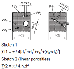
Examples of inner defect calculation are given in the Table C-1.
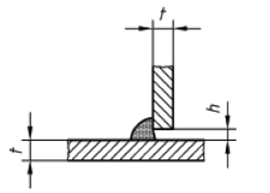
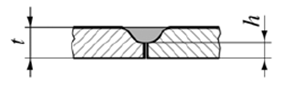
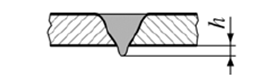
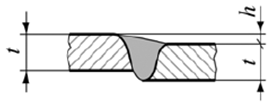
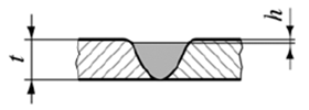
Outer features for fusion welds
Fusion welding shall be performed in conformance with the outer features from Table 101.
The data of Table 101 is based on DIN 29595:2007-04 Table 1 "Limits for external imperfections – Quality levels". Reproduction of this table was granted by DIN.
Table 101: Outer features for fusion welds
Reproduced by permission of DIN Deutsches Institut für Normung e.V. The definitive version for the implementation of this standard is the edition bearing the most recent date of issue, obtainable from Beuth Verlag GmbH, Burggrafenstraße 6, 10787 Berlin, Germany.
|
Serial Number
|
Reference according to ISO 6520-1
|
Designation and Remarks
|
Process reference per ISO 4063
|
Material Group (a)
|
Limits for imperfections for quality levels (b)
| ||
|
A
|
B
|
C
| |||||
|
1
|
502
|
Excess weld metal
|
141, 15
|
A B C
|
h ≤ 0,2t + 1,2 mm
|
h ≤ 0,2t + 2,0 mm
| |
|
D
|
h ≤ 0,2t + 1,8 mm
|
h ≤ 0,2t + 2,5 mm
| |||||
|
511, 52
|
A B C D
|
h ≤ 0,3t ≤ 5 mm
| |||||
|
2
|
511
|
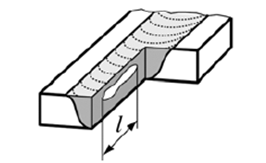
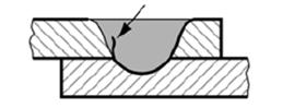
Incomplete filled groove
|
141, 15, 511, 52
|
A B C D
|
Unacceptable
|
h ≤ 0,1t ≤ 1 mm
| |
|
3
|
511
|
Incomplete filled groove
|
511
|
A B C D
|
Unacceptable
|
b ≥ 4h
| |
|
4
|
507
|
Linear misalignment
|
141, 15
|
A B C D
|
h ≤ 0,1 (t1+t2)/2 + 0,25 mm for butt joints
|
h ≤ 0,3 (t1+t2)/2 + 0,3 mm
| |
|
511, 52
|
h ≤ 0,1 (t1+t2)/2 ≤ 1,0 mm
| ||||||
|
5
|
5011, 5012
|
Undercut
|
141, 15
|
A B C D
|
Unacceptable
|
h ≤ 0,1t + 0,1 mm
| |
|
5013
|
Shrinkage groove
|
511, 52
|
h ≤ 0,05t + 0,1 mm
| ||||
|
6
|
|
Flash-over groove
|
511
|
A B C D
|
Unacceptable
| ||
|
7
|
5025
|
Opened crater
|
141, 15
| ||||
|
8
|
2014
|
Surface pore
|
141, 15
|
A B C
|
Unacceptable
|
Length ≤ 0,5t
| |
|
511, 52
|
D
| ||||||
|
9
|
|
Burn
|
141, 15
|
A B C D
|
Unacceptable
| ||
|
10
|
601
|
Arc strike
| |||||
|
11
|
6021
|
Tungsten spatter
| |||||
|
12
|
602
|
Spatter
|
141, 15
|
A B C D
|
Unacceptable
| ||
|
13
|
504
|
Excessive penetration
|
141, 15
|
A B C
|
h ≤ 0,2t + 1,2 mm
|
h ≤ 0,2t + 2,0 mm
| |
|
D
|
h ≤ 0,2t + 1,8 mm
|
h ≤ 0,2t + 2,5 mm
| |||||
|
511, 52
|
A B C D
|
h ≤ 0,3t ≤ 5 mm
| |||||
|
14
|
515
|
Root concavity
|
141, 15
|
A B C
|
Unacceptable
| ||
|
C
|
Unacceptable
|
h ≤ 0,2t
| |||||
|
511, 52
|
A B C D
|
Unacceptable
| |||||
|
15
|
402
|
Incomplete penetration
|
141, 15
|
A B C D
|
Unacceptable
|
Overall ≤ 0,03 weld length
| |
|
511, 52
|
Unacceptable
| ||||||
|
16
|
5212
|
Weld width
|
141, 15
|
A B
|
b ≤ 2t + 4 mm
|
b ≤ 2t + 8 mm
| |
|
141, 15
|
C D
|
b ≤ 2t + 6 mm
|
|
||||
|
17
|
100
|
Cracks
|
141, 15
|
A B C D
|
Unacceptable
| ||
|
18
|
401
|
Lack of fusion
| |||||
|
19
|
510
|
Burn-through
| |||||
|
20
|
506
|
Overlap
|
141, 15
|
A B C D
|
Unacceptable
|
5 % max over a weld length of 100 mm
|
10 % max over a weld length of 100 mm
|
|
511, 52
|
Unacceptable
| ||||||
|
21
|
610
|
Coloration due to temperature
|
141, 15
|
B
|
To be removed unless otherwise specified by design
| ||
|
C
|
See 9.1.2f. for permitted Titanium discoloration
| ||||||
|
22
|
|
Vaporized metal deposition
|
511, 52
|
A B C D
|
Only same type of vaporized metal deposit as base metal is authorized
| ||
|
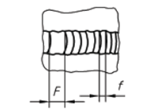
23
|
514
|
Irregular surface (ripple)
|
141, 15
|
A B C D
|
F : f ≤ 4:1
|
F : f ≤ 6:1
|
No specification
|
|
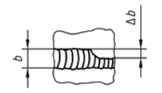
24
|
513
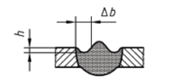
|
Irregular weld width
|
141, 15
|
A B C D
|
Δ b ≤ 0,3b
|
Δ b ≤ 0,4b
|
No specification
|
|
25
|
5214
|
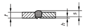
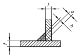
Excessive throat thickness
|
141, 15
|
A B C D
|
h ≤ 0,1a + 1 mm (b)
| ||
|
26
|
5213
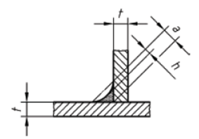
|
Insufficient throat thickness
|
141, 15
|
A B C D
|
Unacceptable
|
h ≤ 0,2a
| |
|
27
|
617
|
Incorrect root gap
|
141, 15
|
A B C D
|
h ≤ 0,2 mm
|
h ≤ 0,4 mm
|
h ≤ 0,8 mm
|
|
(a) A = Unalloyed and low-alloy steels, high-alloy ferritic steels; B = High-alloy austenitic steels; nickel and cobalt alloys; C = Titanium materials; D = Aluminium and magnesium materials.
| |||||||


Inner features for fusion welds
Fusion welding shall be performed in conformance with the inner features from Table 102.
The data of Table 102 is based on DIN 29595:2007-04 Table 1 "Limits for external imperfections – Quality levels". Reproduction of this table was granted by DIN.
Table 102: Inner Features for Fusion Welds
Reproduced by permission of DIN Deutsches Institut für Normung e.V. The definitive version for the implementation of this standard is the edition bearing the most recent date of issue, obtainable from Beuth Verlag GmbH, Burggrafenstraße 6, 10787 Berlin, Germany.
|
Serial Number
|
Reference according to ISO 6520-1
|
Designation and Remarks
|
Process reference per ISO 4063
|
Material Group (a)
|
Limits for imperfections for quality levels (b)
| ||
|
A
|
B
|
C
| |||||
|
28
|
100
|
Cracks
|
141, 15, 511, 52
|
A B C D
|
Unacceptable
|
Limits are to be agreed separately
| |
|
29
|
300
|
Solid inclusions sharp edges
| |||||
|
30
|
401
|
Lack of fusion
| |||||
|
31
|
402
|
Incomplete internal penetration
| |||||
|
32
|
201
|
Gas cavities
|
511, 52
|
A B C
|

  |
To be defined separately
|
Limits are to be agreed separately
|
|
D
|
  |
||||||
|
A B C
|

  |

  |
|||||
|
141, 15
|
D
|

  |
  |
||||
|
(a) A = Unalloyed and low-alloy steels, high-alloy ferritic steels; B = High-alloy austenitic steels; nickel and cobalt alloys; C = Titanium materials; D = Aluminium and magnesium materials.
| |||||||
Features for friction stir welds
Friction stir welding shall be performed in conformance with features from Table 103.
Table 103 reproduced from ISO 25239-5:2011 with the permission of ISO. Copyright remains with ISO. The standard can be obtained from ISO or its members, see www.iso.org.
Table 103: Features for friction stir welds
|
Designation of imperfection
|
Remarks
|
Testing and examination in Clause 4a
|
Acceptance levels in Clause 4a
|
Reference number in ISO 6520-1
|
|
Surface imperfections
| ||||
|
Incomplete root penetration
|
|
ME
|
Not permitted
|
4021
|
|
Excess penetration
|
|
VT, ME
|
h ≤ 3 mm
|
504
|
|
Toe flash
|

|
VT, ME
|
b
|
c
|
|
Linear misalignment
|
|
VT, ME
|
h ≤ 0,2t
|
507
|
|
Underfill
|
|
VT, ME
|
h ≤ 0,1t
|
c
|
|
Irregular width
|
Excessive variation in width of the weld
|
VT
|
b
|
513
|
|
Irregular surface
|
Excessive surface roughness
|
VT
|
b
|
513
|
|
Internal imperfections
| ||||
|
Elongated cavity
|
|
ME
|
l ≤ 0,05t
|
2105
|
|
Hooking
|
|
ME
|
b
|
c
|
|
NOTE 1 t: nominal thickness of the parent material.
| ||||
|
a Testing and examination of other imperfections and their acceptance levels shall be in accordance with the relevant requirements of the design specification.
| ||||
Welding process verification
Weld Samples
General
The weld samples manufactured for the verification shall be representative of flight hardware and include the following:
- Weld machine,
- Fixtures,
- Sample material, and
- Weld interface.
Deviations from requirement 11.1.1a shall be approved by the customer prior to the start of the verification testing.
If the machine used during the verification is different to the one used for the production of flight hardware, then a delta verification shall be performed according to the requirements of the clause 11.3.
The weld pass sequence shall be in compliance to the sequence specified in the WPS from DRD from Annex A.
The type and number of samples shall be specified in conformance with the requirements from clause 11.1.2 to clause 11.1.3.
Safety Classes 1 and 2: assessment of weld samples
To verify the weld data set, the assessment of the weld samples for safety classes 1 and 2 shall be as follows:
- for manual arc welding the minimum number of weld samples in conformance with Table 111.
- for all other welding processes the minimum number of weld samples in conformance with Table 112. Table 111: Minimum acceptable amount of testing for manual arc welding
|
Type of test
|
Sample Number
| ||||
|
Inspection
|
1
|
2
|
3
|
4
|
5
|
|
Visual Inspection
|
X
|
X
|
X
|
X
|
X
|
|
Penetrant Inspection
|
X
|
X
|
X
|
X
|
X
|
|
Radiographic Testing
|
X
|
X
|
X
|
X
|
X
|
|
Metallography and Hardness
|
X
|
|
|
|
X
|
|
Tensile Tests
|
|
X
|
X
|
X
|
|
Table 112: Minimum acceptable amount of testing for all mechanised welding processes class 1 and 2 welds
|
Type of test
|
Sample Number
| |||||||
|
Inspection
|
1
|
2
|
3
|
4
|
5
|
6
|
7
|
8
|
|
Visual Inspection
|
X
|
X
|
X
|
X
|
X
|
X
|
X
|
X
|
|
Penetrant Inspection
|
X
|
X
|
X
|
X
|
X
|
X
|
X
|
X
|
|
Radiographic Testing
|
X
|
X
|
X
|
X
|
X
|
X
|
X
|
X
|
|
Metallography and Hardness
|
X
|
X
|
|
|
|
X
|
|
X
|
|
Tensile Tests
|
|
|
X
|
X
|
X
|
|
|
|
Safety Class 3: assessment of weld samples
For all welding processes from safety class 3, two samples shall be produced and subjected to visual inspection.
Verification acceptance criteria
The samples shall be marked and serialised.
All tests and measurements performed on the samples shall be in compliance with the requirements from clause 11.
In the case when at least one measurement on one sample is non-compliant with the requirements of clause 11, the verification shall be rejected.
Delta verification
General
In case one or more parameters in an approved WPS is changed a delta verification shall be performed.
The decision to perform a delta verification or a complete verification shall be under the responsibility of the welding supervisor.
Delta verification shall be performed on a smaller number of samples, and limited amount of testing compared to the full weld verification.
Safety Classes 1 and 2: delta verification
For all welding processes, the minimum number of weld samples shall be in conformance with Table 113.
Table 113: Minimum acceptable amount of testing for class 1 and 2 welds (all processes)
|
Type of test
|
Sample Number
| |
|
Inspection
|
1
|
2
|
|
Visual Inspection
|
X
|
X
|
|
Penetrant Inspection
|
X
|
X
|
|
Radiographic Testing
|
X
|
X
|
|
Metallography and Hardness
|
X
|
|
|
Tensile Tests
|
|
X
|
Safety Class 3: delta verification
For all welding processes from safety class 3, only 2 samples shall be produced for delta verification.
Both samples shall be subjected to visual inspection.
Re-weld, in process correction
After the welding operation has been completed, visual examination shall be performed by the welding operator and the welding supervisor.
Re-welding shall be verified using the same method as for delta verification.
When a delta verification is performed, two additional welds shall be produced for re-welding.
In case defects are observed, then a maximum of two attempts may be made for in-process correction.
Defects include undercut, underfill, suck-back, craters, incomplete fusion, incomplete penetration, cracks, overlaps, weld reinforcement, protrusions.
The use of in-process correction shall be documented in the inspection report and shop traveller.
In case the two pre-weld attempts cannot result in the required level of in process correction, the following shall be performed.
- an NCR is raised in conformance with requirements from clause 5 of ECSS-Q-ST-10-09.
- repair welding is performed in accordance with the requirements from clause 11.5.
Repair welding
Repair welding shall only be allowed following the raising of an NCR in conformance with requirements from clause 5 of ECSS-Q-ST-10-09.
NCR shall be raised in the following cases:
- When the wrong filler metal has been used.
- When a weldment has been post weld heat treated to increase the strength and cannot be returned to drawing requirements with additional heat treatments after re-weld.
- When finish machining has been completed prior to re-welding.
- When the repair extends outside the original weld zone For weld repair which requires additional welding, the defective part shall be removed so that after visual inspection, the defect is no longer present.
Acceptable methods of defect removal includes grinding or chipping.
After removal of the defective part, the area shall be visually inspected.
Repair welding shall be performed using a WPS which is approved for weld repair.
Re-inspection of all repair weld areas shall be performed using the same methods and requirements as the original weld.
For multiple welds, it shall be demonstrated that design strength requirements are met in any given area.
Documentation
For the verification of the welding process, the following documents shall be issued:
- WVTP in conformance with the DRD from Annex B.
- Welding verification test report (WVTR) in conformance with DRD from Annex C of ECSS-E-ST-10-02.
- WPS in conformance with the DRD from Annex A for every dimension and material combination.
Tailoring of the WVTP for other tests shall be agreed with the supplier and customer.
Documents specified in the requirements from 11.6a.1 to 11.6a.3 and 11.6b shall be controlled in conformance with ECSS-M-ST-40.
Flight hardware production
Documentation
Prior to the start of manufacturing the following documents shall be made available and approved by the welding supervisor:
- WVTR
- Complete set of drawings
- Manufacturing parameters listed in the WPS from DRD from Annex A.
Any welding performed on flight hardware shall be in conformance with the requirements from the approved WPS.
Any welding performed on flight hardware shall be performed under configuration control.
Requirements for flight hardware welding
General
The preparation of a shop traveller shall be completed.
Only qualified weld data sets shall be used for the welding of flight hardware.
Drawing set and the corresponding documents and specifications shall be issued and approved by the welding supervisor.
Details for welding shall be indicated in the respective drawing set and the corresponding documents and specifications.
During test or final assembly of the piece parts, the cleanliness requirements of clauses 7.3.4c and 8.1.5 shall apply.
The responsible welding supervisor or the designated representative shall ensure that requirements specified in requirements from 12.2.1a to 12.2.1e are fulfilled prior the start of flight hardware welding.
To avoid exceeding the maximum relative humidity, Table 121 shall be applied.
Table 121: Dew point conditions for welding
|
Tair - Tmetal
|
Relative Humidity
| |
|
°F
|
°C
|
%
|
|
0
|
0
|
100
|
|
3
|
2
|
90
|
|
6
|
3
|
80
|
|
10
|
5
|
70
|
|
14
|
8
|
60
|
|
19
|
11
|
50
|
|
25
|
14
|
40
|
|
32
|
18
|
30
|
|
42
|
23
|
20
|
|
58
|
32
|
10
|
The environmental conditions shall be maintained during the flight hardware welding in conformance with the requirements from clause 8.1.5.
Malfunctions of the welding equipment shall be documented in the Logbook in conformance with the DRD from Annex C from ECSS-Q-ST-20.
Drawings
Every drawing that shows weld seam shall be in conformance with clauses 1 to 7 of the standard ISO 2553:2013.
The drawing shall contain the following information:
- Base material type and condition at the time of welding,
- Filler metal type, commercial appellation or autogenous weld,
- Post weld mechanical or thermal treatment or both,
- Welding process number in conformance with ISO 4063:2009,
- Welding Safety Class:1, 2 or 3,
- Welding sensitivity level: A, B, or C,
- Additional inspection methods plus acceptance criteria.
- 1 For the requirement 12.2.2b.1 example of base material type and condition is thermal treatment.
- 2 For the requirement 12.2.2b.2 autogenous weld is without filler.
Extent of testing to support flight hardware production
The inspection criteria for flight hardware production shall be in conformance with Table 122.
The application of the inspection criteria specified in the requirement 12.2.3a shall be in conformance with DIN 29595:2007-04 and depends on the Safety Class of the weld.
In the case when welds are not penetrant inspected alternative methods shall be applied.
Examples of applications where alternative methods can be applied include tanks, heat pipes.
For process control, deviations from requirement specified in 12.2.3a, shall be approved by the customer.
This depends on the equipment and on the tests done after manufacture for example. leak test.
Prior to flight hardware production, application of Alpha and Beta samples or alternative weld control technique in compliance with the Table 122 shall be agreed with the customer.
- 1 Alternative weld control techniques can include tapered sample, tapered tube.
- 2 Alternative test methods which can be considered include proof test, leak test.
Techniques specified in the requirement 12.2.3e shall be: - Demonstrated during verification, and
- Results approved by the customer. Table 122: Tests to be performed on parts performed during production of flight hardware
|
Class
|
Visual and Dimensional Inspection
|
Penetrant Inspection
|
Radiographic or Ultrasonic Inspection
|
|
Class 1
|
100 %
|
100 %
|
100 %
|
|
Class 2
|
100 %
|
100 %
|
Radiographic inspection for welds as appropriate for intended use
|
|
Class 3
|
100 %
|
Not required
|
Not required
|
Quality assurance
Maintenance of WPS
All changes to the WPS from DRD from Annex A shall be controlled in conformance with t ECSS-M-ST-40.
As a result of modifications to the welding process specified in the requirement 13.1a, the WPS from DRD from Annex A shall be updated.
For example, changes to the jigs, parameter changes.
Modifications to welding parameters which fall outside the WPS shall lead to the issue of a new weld configuration.
In case of an issue of a new weld configuration specified in the requirement 13.1c the existing welding configuration shall become obsolete.
Every change in the existing welding configuration shall be agreed with the customer to specify if a re-verification or delta verification is necessary.
Quality control
Reference samples
The welding of the reference sample shall be performed under the same conditions as the corresponding flight hardware.
Examples of the same conditions are the same weld data, weld head, weld machine, weld sequence.
Reference samples shall be stored in conformance with life duration of the mission.
Examples of reference samples includes alpha and beta samples.
Documentation of weld parameters
The data generated during mechanised welding shall be recorded in the shop traveller.
All mechanised weld data shall be available for review.
Anomalies and nonconformances occurring during the welding process
In case of anomalies occurring during the welding process, leading to the welding activities to be stopped in a controlled manner, the weld operators shall inform the responsible welding supervisor or the designated representative.
An unexpected change in one or more process parameters can be considered as anomalies.
For Safety Classes 1 and 2, all anomalies identified in compliance with the requirement 13.2.3a shall:
- be classified as major, and
- a major NCR in conformance with clause 5 of ECSS-Q-ST-10-09 be raised.
For Safety Class 3, when an anomaly identified in compliance with the requirement of 13.2.3a is classified as major, a major NCR in conformance with clause 5 of ECSS-Q-ST-10-09 shall be raised.
For Safety Class 3, when an anomaly identified in compliance with the requirement of 13.2.3a is classified as minor, a minor NCR shall be raised in conformance with clause 5 of ECSS-Q-ST-10-09.
Malfunctions of the welding equipment shall be documented in the maintenance book.
Malfunctions of the welding equipment shall be reported to the responsible welding supervisor or his designated representative informed.
A NCR shall be raised in case a flight part is affected by the equipment malfunction.
All the major and minor anomalies shall be recorded and made available for the customer to review upon request.
Inspection and test methods
Inspection shall be performed on welds to demonstrate that the welds are compliant with the requirements of design and drawing for all weld classes in conformance with the requirements from the clauses 9.1 and 9.2.
Any nonconformance shall be recorded and made available to the customer.
ANNEX(normative) Welding Procedure Specification (WPS) - DRD
Requirement identification and source document
This DRD is called from the ECSS-Q-ST-70-39, requirement 5.1d.
Purpose and objective
The purpose of the Welding Procedure Specification is to ensure that all relevant information relating to the production of each welded joint is documented in sufficient detail such that this information can be subsequently used to reproduce the welded joint.
Expected response
Scope and content
General
General information
The WPS shall include the date, issue and revision number.
The WPS shall contain the following information:
- Welding process,
- Welding direction,
- Welding position,
- Material combination,
- Joint type,
- Pre-weld cleaning procedure. Drawings
Every drawing that shows a weld seam shall contain the following information:
- Base material type and thermal condition at the time of welding,
- Filler metal type,
- Post weld mechanical or thermal treatment,
- Welding process number in accordance with ISO 4063:2009,
- Welding Safety Class: 1, 2 or 3,
- Welding Sensitivity Class: A, B or C,
- Inspection methods, and
- Acceptance criteria.
For weld preparation joint design and dimension shall be specified in the engineering drawing.
The weld run sequence shall be given on the engineering drawing.
Manufacturer
The WPS shall define the manufacturer as follows:
Identification of the lower tier supplier who performs the welding,
Reference to the WPVR or other applicable documents.
Equipment
The WPS shall include the identification of the equipment, model and serial number, used to perform the welding.
- 1 In the WPS sufficient details are provided to identify the welding machine.
- 2 Examples of equipment include robots, welding torch, laser welding head etc.
Backing and shielding gas
The following backing and shielding gas data shall be included in WPS:
- The method and type of backing,
- Backing material and dimensions,
- The composition,
- Shield gas type,
- Shield gas flow rate,
- Location of the shield gas,
- Duration of the shield gas. Pre-heating and post-weld heat treatment
In case pre-heating is applied, the temperature, and the time at temperature, shall be included in the WPS.
This includes a description of any other instructions related to the heat treatment.
In case a post weld heat treatment is applied, the temperature and the time at temperature shall be included in the WPS.
This includes a description of any other instructions related to the heat treatment.
In the case when the laser beam used for the welded joint is used for preheating or post-weld heat treatment, the relevant parameters for the preheating or post-weld heat treatment shall be recorded in the WPS.
Tooling and fixtures
Tooling and fixtures shall be identified in the WPS.
Justification to deviation from the requirement 7.3.4h shall be specified.
Non-destructive inspection
All non-destructive inspection techniques shall be identified in the WPS including the following acceptance criteria:
- Radiographic Inspection,
- Ultrasonic inspection,
- X-Ray tomography (CT Scan). Additional requirements for various welding processes
Mechanised metal arc welding
In addition to the requirements specified in the clause A.2.1<1>, the WPS for mechanised arc welding shall contain as a minimum, the following additional information:
- Electrical parameters:
- Type of current: AC or DC and polarity,
- Pulse welding details: machine settings, programme selection,
- Current range,
- Voltage range,
- Slope profile.
- Mechanical parameters:
- Travel speed range,
- Wire or strip feed speed range.
- In case the equipment does not permit control of one of either variable specified in the requirements A.2.1<2.1>a1 and A.2.1<2.1>a2, the machine settings are specified instead.
- Other parameters:
- Torch, electrode or wire angle,
- For mechanized and automatic welding maximum weaving or amplitude, frequency and dwell time of oscillation.
For the requirement A.2.1<2.1>a3 the range of application for the WPS is then limited to equipment of that particular type.
Gas-shielded metal arc welding: process 13
In addition to the requirements specified in the clausesA.2.1<1> and A.2.1<2.1>, the WPS for gas-shielded metal arc welding shall contain as a minimum, the following additional information:
- Shielding gas flow rate and nozzle diameter,
- Number of wire electrodes,
- Additional filler material,
- The distance from the contact tip or contact tube to the surface of the workpiece,
- Arc voltage range, and
- Mode of metal transfer. Gas-shielded welding with non-consumable electrode: process 14
In addition to the requirements specified in the clauses A.2.1<1> and A.2.1<2.1>, the WPS for gas-shielded welding with non-consumable electrode shall contain as a minimum, the following additional information:
- Tungsten electrode: the diameter, and codification in accordance with of ISO 6848:2004,
- Shielding gas flow rate and nozzle diameter,
- Additional filler materials,
- Welding direction, backhand or forehand,
- Application of AVC.
Thoriated electrodes are not usually used due to health reasons.
Plasma arc welding: process 15
In addition to the requirements specified in the clauses A.2.1<1> and A.2.1<2.1>, the WPS for plasma arc welding shall contain as a minimum, the following additional information:
- Plasma nozzle design,
- Plasma gas parameters,
- Shielding gas flow rate and nozzle diameter,
- Type of torch,
- Distance contact tube or work piece,
- Welding direction, hand orientation,
- Application of AVC.
- 1 For the requirement A.2.1<2.4>a2 parameters include composition, nozzle diameter, and flow rate.
- 2 For the requirement A.2.1<2.4>a5 the distance defined as the distance from the nozzle to the surface of the work piece.
Electron beam welding: process 51
In addition to the requirements specified in the clause A.2.1<1>, the WPS for electron beam welding shall contain as a minimum, the following information:
- Equipment:
- Model and make,
- Electron gun type, and
- Cathode type.
- A schematic diagram showing the design, position of the filler material feeding system in relation to joint, welding direction and welding point.
- Electrical parameters:
- Accelerating voltage in kV,
- Beam current in mA,
- Focusing lens current(s) in A, current control device setting(s) (arbitrary units) or focus position with respect to workpiece surface,
- Beam deflection,
- DC deflection, dimensions at work piece surface,
- AC oscillation: shape, and orientation with respect to the welding direction, frequency in Hz, dimensions (mm of deflection),
- Overlap, slope up, slope down [in seconds (s), millimetres (mm) or degrees (deg)],
- Slope profile.
- Mechanical parameters:
- Travel direction,
- Surface travel speed (mm/min or mm/s),
- Travel speed ramping details,
- Wire or filler feed rate, direction, position and angle.
- Other parameters:
- Working distance in mm or gun to work distance,
- Pressure in the gun in Pa or mbar,
- Pressure in the chamber in Pa or mbar.
For the requirement A.2.1<2.5>a3(b) pulse parameters to be specified if pulsing is used.
Laser beam welding: process 52
In addition to the requirements specified in the clause A.2.1<1>, the WPS for laser beam welding shall contain as a minimum, the following information:
- Equipment:
- Type of source, model and make,
- Nominal power,
- Continuous wave or pulsed,
- Number of lasers combined.
- Manufacturer’s or measured values for the beam quality parameters:
- Beam transverse electro-magnetic mode,
- Beam divergence,
- Wavelength,
- Beam polarization and orientation,
- Beam parameter product.
- Beam delivery and Focusing System:
- Method of transmission,
- Method of beam shaping,
- Distance from beam source to focusing system,
- Beam diameter on entrance to focusing system,
- Focusing optics,
- Focal length,
- Nominal focal spot size and method of measuring,
- Beam path protection system.
- Process gas supply system:
- A description, schematic diagram, showing design, position of nozzle(s) for plasma suppression gas in relation to the joint, welding direction and welding point.
- Operation(s) and dimensions of the molten pool protection.
- In the case of overlay welding, the composition and flow rate of the gas stream carrying the powder metal.
- A schematic diagram showing the design, position of the filler material feeding system in relation to the joint, welding direction and welding point.
- Laser beam power at the workpiece.
- Laser beam orientation, polarization and position in relation to joint and welding direction:
- angles in two directions,
- position in transverse direction.
- Pulse parameters, including:
- Peak power,
- Pulse energy,
- Repetition rate,
- Pulse duration,
- Pulse shape,
- Power ramping details including slope down or slope up procedure,
- Tacking pass details,
- Oscillation pattern, amplitude, frequency and dwell time.
- Mechanical parameters:
- Travel speed,
- Travel speed ramping details,
- Wire or filler feed rate, direction, position to be specified and angle.
- Plasma suppression gas, shielding and backing gas parameters:
- Gas flow rate,
- Checking of gas purity,
- Purge procedure.
- Run geometry and sequence for overlay welding.
- For overlay welding, the description of the sequence of runs includes:
- Width and the height of the single run, and
- Distance or percentage of the overlap.
- Other parameters:
- Working distance,
- Shape and dimensions of the beam on the workpiece, and
- Location and orientation of the shielding gas nozzle with respect to the workpiece.
- 1 For the requirement A.2.1<2.6>a1(a) example source type includes Nd: YAG or CO2.
- 2 For the requirement A.2.1<2.6>a2(a) examples of methods of transmission includes fibres, mirrors, including beam collimators.
- 3 For the requirement A.2.1<2.6>a2(b) examples of beam shaping includes scanner, integrator, diffractive lenses.
Friction stir welding: process 43
In addition to the requirements specified in the clause A.2.1<1>, the WPS for friction stir welding shall contain as a minimum, the following information:
- Equipment:
- Model,
- Serial number,
- Manufacturer,
- Tool identification,
- Material,
- Drawing or drawing number,
- Trade name.
- Clamping arrangement:
- Method and type of jigging, fixtures, rollers, and anvil,
- Fusion tack welding in accordance with ISO 15614-2:2005 or friction stir tack welding process and conditions,
- Indication of applicable tack welding or indication of the case if tack welding is prohibited.
- Weld start and termination:
- Weld start location and exit hole location,
- Run-on and run-off plates, and parent material and reference standard.
- Welding parameters:
- Tool motion,
- Heel plunge depth, axial force,
- Tilt angle,
- Side tilt angle,
- Dwell time,
- Joint configuration,
- Lapped length between start and end of welds for a butt joint in tube,
- Lap joint: advancing or retreating side near the top sheet edge, direction of welding,
- Weld run sequence and direction given on the sketch.
- Welding speed
- Welding speed, including details of any changes,
- Ramp up or ramp down speed.
- Pre-heating:
- Pre-heating of friction stir welding tool,
- Pre-heat maintenance temperature.
- Working temperature.
For the requirement A.2.1<2.6>a4(a) examples of tool motion are rotation in either the clockwise or anti-clockwise direction, rotation speed including ramp-up or ramp-down.
Rotary friction welding: process 42
In addition to the requirements specified in the clause A.2.1<1>, the WPS for rotary friction welding shall contain as a minimum, the following information:
- Welding parameters:
- Rotation Speed: peripheral velocity,
- Axial force: Approach, Friction and Forge,
- Burn-off: rubbing distance or time,
- Burn-off rate: force application rate during friction,
- Forge application rate,
- Spindle deceleration rate or efficiency,
- Braking,
- Flywheel mass,
- Motor power.
- Other parameters:
- Squareness,
- Concentricity.
Linear friction welding: process 42
In addition to the requirements specified in the clause A.2.1<1>, the WPS for linear friction welding shall contain as a minimum, the following information:
- Welding parameters:
- Oscillation frequency [Hz],
- Oscillation amplitude [+/- mm],
- Normal friction pressure [MPa],
- Normal forge pressure [MPa],
- Forge trigger mode,
- Burn-off distance [mm],
- Absolute distance [mm], time [s]),
- Forge duration [s],
- Shape of the waveform [sine],
- Oscillation amplitude ramps [mm/s],
- Forge ramps [MPa/s].
Magnetic pulse welding: process 442
In addition to the requirements specified in the clause A.2.1<1>, the WPS for magnetic pulse welding shall contain as a minimum, the following information:
- Welding parameters:
- Magnetic force, field intensity,
- Collision angle,
- Duration of discharge,
- Initial stand-off distance between the mating surfaces,
- Overlapping distance,
- Coil geometry.
Hybrid laser-MIG welding
In addition to the requirements specified in the clause A.2.1<1>, the WPS for hybrid laser-MIG welding shall contain as a minimum, the following information:
- For the laser beam welding part of the process, the requirements of clause A.2.1<2.6>.
- For the arc welding part of the process, the requirements of clause A.2.1<2.2>.
- Additional parameters:
- Welding direction,
- Distance between laser beam and electrode axis on workpiece surface related to weld centre line,
- Angle between laser beam and electrode axes.
For the requirement A.2.1<2.11>a3(a) welding direction includes the relative position of the arc and laser beam welding equipment. For example, is the laser leading or trailing the arc.
Special remarks
None.
ANNEX(normative)Welding Verification Test Plan (WVTP) - DRD
DRD identification
This DRD is called from the ECSS-Q-ST-70-39, requirement 11.6a.1.
Purpose and scope
The purpose of the welding verification test plan (WVTP) is to ensure that all relevant information relating to the test plan is documented in sufficient detail such that this information can be subsequently used to produce the required results.
Expected response
Scope and content
General
The WVTP shall include the date, issue and revision number.
The WVTP shall include the following information:
- Welding process,
- Welding direction,
- Welding position,
- Material combination,
- Joint type,
- Pre-weld cleaning procedure. Drawings
Drawings shall be in conformance with the requirements specified clause A.2.1<1.2>.
Backing and shielding gas
Backing and shielding gas shall be in conformance with the requirements specified in the clause A.2.1<1.5>.
Pre-heating and post-weld heat treatment
Pre-heating and post-weld heat treatments shall be in conformance with the requirements specified in the clause A.2.1<1.6>.
List of tests for weld verification
The types of test required for the weld verification shall be in conformance with the requirements from clause 10.1.
Weld samples to be tested
The number and type of weld samples to be tested shall be in conformance with the requirements from clause 10.1.
Criteria of acceptance
The criteria of acceptance of a weld shall be in conformance with the requirements from clause 9.
Weld inspection
Weld inspection shall be in conformance with the requirements from clause 8.
Special remarks
None.
ANNEX(informative)Inner defect calculation
Examples of inner defect calculation are given in the Table C-1.
The data of Table C-1 is based on DIN 29595:2007-04 Table 4 "Calculated permissible sizes of internal imperfections (201, 2011, 2012, 2013, 300". Reproduction of this table was granted by DIN.
Table: Inner Defect Calculation
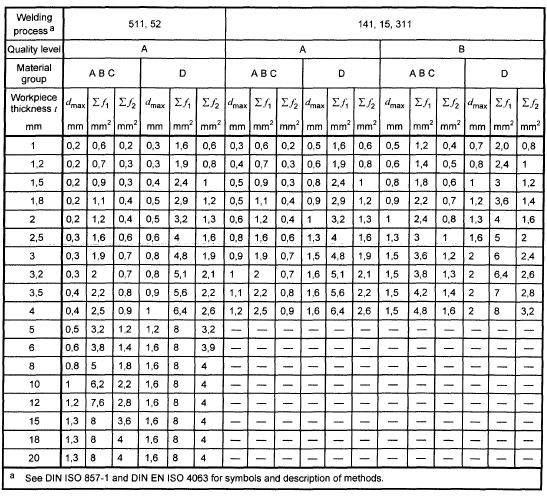 Reproduced by permission of DIN Deutsches Institut für Normung e.V. The definitive version for the implementation of this standard is the edition bearing the most recent date of issue, obtainable from Beuth Verlag GmbH, Burggrafenstraße 6, 10787 Berlin, Germany.
Bibliography
|
ECSS-S-ST-00
|
ECSS system – Description, implementation and general requirements
|
|
EN 571-1:1997
|
Non-destructive testing - Penetrant testing - General principles
|
|
ASTM E8M-13
|
Standard test methods for tension testing of metallic materials
|
|
ASTM E384-11
|
Standard test method for Knoop and Vickers hardness of materials
|
|
QPL AMS 2644-4
|
Qualified Products List of Products qualified under sae aerospace material specification SAE AMS 2644 - Inspection material, penetrant
|