
Space engineering
Time-Triggered Ethernet
Foreword
This Standard is one of the series of ECSS Standards intended to be applied together for the management, engineering, product assurance and sustainability in space projects and applications. ECSS is a cooperative effort of the European Space Agency, national space agencies and European industry associations for the purpose of developing and maintaining common standards. Requirements in this Standard are defined in terms of what shall be accomplished, rather than in terms of how to organize and perform the necessary work. This allows existing organizational structures and methods to be applied where they are effective, and for the structures and methods to evolve as necessary without rewriting the standards.
This Standard has been prepared by the ECSS-E-ST-50-16C Working Group, reviewed by the ECSS Executive Secretariat and approved by the ECSS Technical Authority.
Disclaimer
ECSS does not provide any warranty whatsoever, whether expressed, implied, or statutory, including, but not limited to, any warranty of merchantability or fitness for a particular purpose or any warranty that the contents of the item are error-free. In no respect shall ECSS incur any liability for any damages, including, but not limited to, direct, indirect, special, or consequential damages arising out of, resulting from, or in any way connected to the use of this Standard, whether or not based upon warranty, business agreement, tort, or otherwise; whether or not injury was sustained by persons or property or otherwise; and whether or not loss was sustained from, or arose out of, the results of, the item, or any services that may be provided by ECSS.
Published by: ESA Requirements and Standards Section ESTEC, P.O. Box 299, 2200 AG Noordwijk The NetherlandsCopyright: 2021© by the European Space Agency for the members of ECSS## Change log
|
ECSS-E-ST-50-16C
|
First issue
|
Scope
Using standard communication protocols for spacecraft communication links can provide interface compatibility between communication devices and components. Thus, it can improve the design and development process as well as integration and test activities at all levels and provide the potential of reusability across projects.
The aim of this space engineering standard is to define the interface services and to specify their corresponding network protocol elements for spacecraft using the Time-Triggered Ethernet data network. It also aims at defining requirements for the harmonisation of the physical interfaces and usage of the [IEEE 802.3] and [SAE AS6802] layer features.
This standard may be tailored for the specific characteristic and constraints of a space project in conformance with ECSS‐S‐ST‐00.
Approach
The approach of the ECSS working group for defining this standard aims at identification of layers, services and functions of the typical Time-Triggered Ethernet communication network to ensure the use of the technology for various space projects. The standard aims at:
Identifying Reference Architectures (Layers, Services, Functions and Elements of protocol) of typical Time-Triggered Ethernet communication network;
Characterizing Services, Functions and Elements of Protocol of each Layer within identified Reference Architectures, using concrete project specifications;
Define normative requirements rather than recommendations.
As far as possible, the defined communication requirements are extracted from the experience on existing spacecraft specifications.
Normative references
The following normative documents contain provisions which, through reference in this text, constitute provisions of this ECSS Standard. For dated references, subsequent amendments to, or revision of any of these publications do not apply. However, parties to agreements based on this ECSS Standard are encouraged to investigate the possibility of applying the more recent editions of the normative documents indicated below. For undated references, the latest edition of the publication referred to applies.
|
ECSS-S-ST-00-01
|
ECSS System - Glossary of terms
|
|
ARINC 664 part 7, 23 September 2009
|
Aircraft Data Network Part 2: Avionic Full-Duplex Switched Ethernet Network
|
|
IEEE 802.3, 28 December 2012
|
Ethernet Standard
|
|
SAE AS6802, November 2011
|
Time-Triggered Ethernet
|
|
RFC 768, 28 August 1980
|
User Datagram Protocol (UDP)
|
|
RFC 791, September 1981
|
Internet Protocol (IP)
|
|
RFC 792, September 1981
|
Internet Control Message Protocol (ICMP)
|
|
RFC 1157, May 1990
|
A simple network management protocol (for SNMPv1)
|
|
RFC 1350, July 1992
|
The TFTP Protocol (Revision 2)
|
Terms, definitions and abbreviated terms
Terms from other standards
For the purpose of this Standard, the terms and definitions from ECSS-S-ST-00-01 apply.
Terms specific to the present standard
acceptance window
timing interval in which the reception of the frame associated with a VLID is expected
bandwidth allocation gap
minimum delay between two consecutive Rate-Constrained frames belonging to the same sending interval
[ARINC 664 part 7]
Best-Effort traffic
standard Ethernet frame which is neither critical traffic nor flow controlled traffic
A Best-Effort frame or traffic as specified by the standard [IEEE 802.3].
broadcast
transmission of an Ethernet frame from one sender to all receivers
cluster
Ethernet network composed of nodes synchronized to each other by the Time-Triggered Ethernet protocol
compression master
role of an element of the cluster that collects protocol control frames (PCFs) from the synchronization masters and uses them in a timing algorithm (compression) before sending them back to the configured synchronization masters and synchronization clients, to be used for synchronization purposes
critical traffic
flow of critical traffic frames, where each frame has the most significant 32 bits set to the critical traffic marker
Critical Traffic Marker is the value of the most significant 32 bits of the MAC Destination Address that identifies a frame as Critical Traffic.
device
element of an Ethernet network or an element connected to an Ethernet node
A device can be either a Switch or an End-System or a host computer. A device does not necessarily support RC or TT or BE traffic.
End-System
network component which provides the host device an interface to the network
Each host device uses an End-System interface to guarantee a secure and reliable data interchange with other host device.
flow controlled traffic
sequence of Ethernet packets from one sender to one or multiple receivers
A Flow controlled traffic as specified by [RFC 3697].
frame
part of a packet
- 1 The following frame types are used throughout this document:
- Best-Effort frame: Basic Frame
- Critical Traffic frame: Rate-Constrained (RC) frame; Protocol Control Frame (is a RC frame); Time-Triggered (TT) frame
- 2 Example of a packet is shown in Figure 3-1.
globally administered MAC
unique MAC address assigned to the network interface card by the manufacturer
link
physical connections between nodes in a network providing the means for transferring frames between them
locally administered MAC
unique MAC address assigned to the network interface card locally
multicast
transmission of an Ethernet frame from one sender to multiple receivers
node
element of an Ethernet network
A node can be either a Switch or an End-System. A node does not necessarily support RC and TT traffic but at least BE.
packet
complete Ethernet message including the header information consisting of the preamble and the start of frame delimiter
The Ethernet packet is specified in, 1000Base-X PCS, [IEEE 802.3] Clause 36 [2], section 1/section 3 ”Media Access Control (MAC) frame and packet specifications”. The structure is shown in Figure 3-1.
 Figure 3-1: Structure of a Packet
protocol control frame
standard Ethernet frame whose Ethernet type field is set to 0x891D, which is used by the synchronization protocol
[SAE AS6802]
raster granularity
timeline on which scheduling events are placed
Rate-Constrained
guaranteed bandwidth traffic as specified by the standard
[ARINC 664 part 7]
schedule table
time schedule of transmission and reception events for critical traffic.
Switch
hardware device that connects multiple End-Systems or Switches to one network
A Switch works on Layer 2 of the Ethernet specification and has two different ways of packet switching between the different devices connected to its Ethernet ports which are static and dynamic switching. The static packet switching works according to a defined static switching table. Dynamic switching describes an automated forward path for a given MAC destination address based on the current network architecture.
synchronization client
role of an element of the cluster that consumes protocol control frames (PCFs) received from compression masters for synchronization purpose, without actively participating in the network synchronization process
synchronization master
role of an element of the cluster that generates protocol control frames (PCFs), transmits them to the compression masters, and consumes PCFs received from compression masters for synchronization purpose, actively participating in the network synchronization process
synchronization precision
worst-case Local Clocks offset between any two correctly synchronised End-Systems or Switches in the system
The calculation is given in [SAE AS6802] paragraph 3.2.
Time-Triggered frame
Critical Traffic (CT) frame which is sent over the network at predefined times and take precedence over all other frames types, except for Protocol Control Frames
unicast
transmission of an Ethernet frame from one sender to one receiver
virtual link
logical unidirectional connection path between one node towards one or more nodes
[ARINC 664 part 7]
virtual link identifier
least significant 16 bits of the MAC Destination Address of a Critical Traffic Frame
Per definition of the standard [ARINC 664 part 7], the VLID uniquely identifies a multicast group with a dedicated sender of the message and a set of receivers.
Abbreviated terms
For the purpose of this Standard, the abbreviated terms and symbols from ECSS-S-ST-00-01 and the following apply:
|
Abbreviation
|
Meaning
|
|
API |
Application Programming Interface
|
|
ARINC |
Aeronautical Radio Incorporated
|
|
BAG |
Bandwidth Allocation Gap
|
|
BE |
Best-Effort
|
|
CD |
Collision Detection
|
|
CM |
Compression Master
|
|
CRC |
Cyclic redundancy check
|
|
CSMA |
Carrier Sense Multiple Access
|
|
CT |
Critical traffic
|
|
DLL |
Data Link Layer
|
|
ECSS |
European Cooperation for Space Standardization
|
|
EMC |
Electromagnetic compatibility
|
|
ES |
End-System
|
|
ESCC |
European Space Components Coordination
|
|
FCS |
Frame check sequence
|
|
FDIR |
failure detection, isolation and recovery
|
|
FT |
Fault Tolerant
|
|
Gbps |
Giga bit per second
|
|
GMII |
Gigabit media independent interface
|
|
GND |
Ground
|
|
H/W |
Hardware
|
|
IC |
Integrity Checking
|
|
ICMP |
Internet Control Message Protocol
|
|
ID |
Identifier
|
|
IEEE |
Institute of Electrical and Electronics Engineers
|
|
IFG |
Inter frame gap
|
|
IHL |
Internet Header Length
|
|
IP |
Internet protocol
|
|
IP |
Intellectual Property
|
|
ISO |
International Standard Organisation
|
|
LAN |
Local Area Network
|
|
LLC |
Logic Link Control
|
|
LVDS |
Low Voltage Differential Signalling
|
|
MAC |
Media access control
|
|
Mbps |
Mega bit per second
|
|
MIB |
Management Information Base
|
|
MII |
Media independent interface
|
|
OSI |
Open system interconnection
|
|
PCB |
Printed circuit board
|
|
PCF |
Protocol Control Frame
|
|
PCS |
Physical Coding Sub-layer
|
|
PHY |
Physical Layer
|
|
PLS |
Physical Coding Sublayer
|
|
PMA |
Physical Medium Attachment sub-layer
|
|
PMD |
Physical Medium Dependent sub-layer
|
|
QoS |
Quality of service
|
|
RC |
Rate-Constrained
|
|
RM |
Redundancy Management
|
|
SAE |
Society of Automotive Engineers
|
|
SC |
Synchronization Client
|
|
SFD |
Start Frame Delimiter
|
|
SM |
Synchronization Master
|
|
SN |
Sequence number
|
|
SNMP |
Simple Network Management Protocol
|
|
SW |
Switch
|
|
TFTP |
Trivial File Transfer Protocol
|
|
TT |
Time-Triggered
|
|
TTE |
Time-Triggered Ethernet
|
|
UDP |
User Datagram Protocol
|
|
VL |
Virtual Link
|
|
VL-ID |
Virtual Link Identifier
|
Nomenclature
The following nomenclature applies throughout this document:
The word “shall” is used in this Standard to express requirements. All the requirements are expressed with the word “shall”.
The word “should” is used in this Standard to express recommendations. All the recommendations are expressed with the word “should”.
It is expected that, during tailoring, recommendations in this document are either converted into requirements or tailored out.
The words “may” and “need not” are used in this Standard to express positive and negative permissions, respectively. All the positive permissions are expressed with the word “may”. All the negative permissions are expressed with the words “need not”.
The word “can” is used in this Standard to express capabilities or possibilities, and therefore, if not accompanied by one of the previous words, it implies descriptive text.
In ECSS “may” and “can” have completely different meanings: “may” is normative (permission), and “can” is descriptive.
The present and past tenses are used in this Standard to express statements of fact, and therefore they imply descriptive text.
Overview
Reference Model
This Clause provides an overview of the Time-Triggered Ethernet Standard for the use of deterministic Ethernet in space applications. It covers the most important OSI model layers applicable for space applications and extensions providing useful features to the space community.
Time-Triggered Ethernet takes into consideration the [IEEE 802.3], as well as the [ARINC 664 part 7] and is specified in the Time-Triggered Ethernet Standard [SAE AS6802].
[SAE AS6802] Time-Triggered Ethernet standard is a Layer 2 Quality-of-Service (QoS) enhancement that defines Time-Triggered services for Ethernet networks. Time-Triggered Ethernet is designed for the development of highly dependable systems for applications in multiple industries, including integrated systems in aerospace, ground vehicles and industrial process control. It provides the capability for deterministic, synchronous, and congestion-free communication among distributed applications, unaffected by any asynchronous Ethernet traffic load. [SAE AS6802] is fully compatible with lower (1-2) and higher OSI layers (3-7) and is transparent to applications designed to use asynchronous Ethernet (Figure 4-1)
Time-Triggered Ethernet is a full‐duplex, bidirectional, point‐to‐point data link. It encodes data according to [IEEE 802.3] with 10/100/1000Mbps speeds. It further encompasses different media types as copper and fibre.
 Figure 4-1: OSI Reference Model
Physical Layer
The physical level provides the actual interface between the network components including both the mechanical and electrical interface. This Clause covers:
cable construction,
connectors,
cable assemblies, and
PCB and backplane tracking.
Ethernet was developed to meet the EMC specifications of high reliable applications cross industry. However, since there are lots of space applications where power consumption is a key requirement, in some cases, the use of LVDS as physical layer provides advantages over the typical Ethernet physical layer. Since Ethernet specifies also the interface to the Ethernet physical layer transceiver, the media independent interface (MII), this interface can be used with LVDS transceivers to provide a solution for short distances with already available physical layer building block. As illustrated in Figure 4-2, Ethernet specifies the following three different functional layers within the physical layer:
PCS (Physical Coding Sub-layer),
PMA (Physical Medium Attachment sub-layer), and
PMD (Physical Medium Dependent sub-layer)
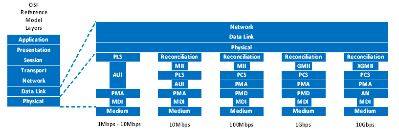 Figure 4-2: Physical Layer Model
Data Link Layer
Data Link Layer Overview
In a Local Area Network (LAN), the Data Link Layer consists of the Media Access Control (MAC) and the Logic Link Control (LLC) Sublayers as illustrated in Figure 4-3.
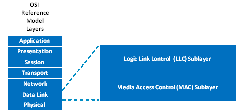 Figure 4-3: Data Link Layer
Data Link Layer Functionalities
The MAC sublayer defines a medium-independent facility, built on the medium-dependent physical facility provided by the Physical Layer, and under the access-layer-independent LAN LLC sublayer (or other MAC client). It is applicable to a general class of local area broadcast media suitable for use with the media access disciplines known as Time-Triggered Ethernet and Carrier Sense Multiple Access with Collision Detection (CSMA/CD).
The LLC sublayer and the MAC sublayer together are intended to have the same function as that described in the OSI model for the Data Link Layer alone. In a broadcast network, the notion of a data link between two network entities does not correspond directly to a distinct physical connection. Nevertheless, the partitioning of functions requires three main functions generally associated with a data link control procedure to be performed in the MAC sublayer. They are as follows:
Data encapsulation (transmit and receive):
Framing (frame boundary delimitation, frame synchronization)
Addressing (handling of source and destination addresses)
Virtual Link handling
Error detection (detection of physical medium transmission errors)
Media Access Management
Medium allocation (collision avoidance)
Contention resolution (collision handling)
Network Synchronization
Start-Up Service
Restart Services
Fault-Tolerant Clock Synchronization Service
The Media Access Management is not covered to a very large extend since this can be implemented as defined in the [IEEE 802.3]. For Time-Triggered traffic this is handled via the configurations of the devices in the network according to the global schedule created by the configuration tools. Also for Rate-Constrained traffic the flow-control of [IEEE 802.3] according to [ARINC 664 part 7] has to be disabled.
Time-Triggered Ethernet
Time-Triggered Ethernet specifies Time-Triggered services that are added to the standards for Ethernet established in [IEEE 802.3]. Figure 4-4 shows a parallel view of the Time-Triggered services and the common Open Systems Interconnection OSI model layers. A communication controller that implements the Time-Triggered services can synchronize its local clock with the local clocks of other communication controllers and Switches in the system. A system designer can define an offline schedule of frame transmission with respect to the synchronized time, and the Time-Triggered Ethernet devices can then dispatch frames according to this schedule. Such a transfer of a frame according to a synchronized time is called a “Time-Triggered transfer”. Offline scheduling tools can be used to guarantee that Time-Triggered transfers are conflict-free (i.e., no two Time-Triggered frames compete for transmission). Time-triggered communication is not priority-based and is driven only by time progression and frame schedule. This prevents network traffic congestion for Time-Triggered frames and enables communication with fixed latency in Ethernet networks, unaffected by any asynchronous Ethernet traffic load.
In addition to the Time-Triggered transfer service, a synchronized global time is used to specify temporal characteristics for intervals in which non-Time-Triggered communication can occur. This allows Time-Triggered Ethernet device implementations to support communication among applications with different real-time requirements over a single physical network. For example, in a particular Time-Triggered Ethernet system, there can be three different traffic classes (see Figure 4-4):
Time-Triggered TT [SAE AS6802],
Rate-Constrained RC [ARINC 664 part 7], and
Best-Effort BE [IEEE 802.3].
 Figure 4-4: Time-Triggered Ethernet Services
Time-Triggered transfers (TT) best suit communications distributed in real-time systems. Tight latency, jitter, and determinism requirements can necessitate the use of TT transfers. All TT transfers are dispatched at predefined times. In cases where an End-System decides not to use its assigned time slot (e.g., if there is no new data to send), the Switch recognizes the inactivity of the sender by not receiving the TT frame within the acceptance window and frees the bandwidth for the other traffic classes immediately afterwards.
Rate-Constrained transfers (RC) define the maximum allowed bandwidth use for a dedicated message to ensure bounded latency in complex networks. Successive transfers of RC frames belonging to the same Rate-Constrained dataflow are guaranteed to be offset by a minimum duration as specified offline. This is in contrast to TT communication, which in addition to the minimum duration also specifies a maximum duration for this interval. The RC communications paradigm is specified in the standard [ARINC 664 part 7]. A system designer can decide to use RC transfers when determinism and real-time operating requirements are less strict than those that drive the use of TT communication. RC transfers guarantee sufficient bandwidth allocation for each transmission, with defined limits for delays and temporal deviations. In contrast to TT transfers, RC transfers are not dispatched with respect to a system-wide synchronized time base. Hence, different communication controllers can dispatch RC-transferred frames at the same point in time. Consequently, the RC transferred frames can queue up in the network Switches, leading to increased transmission jitter and requiring increased buffer space. Given the known transmission rate of the RC transfers and the network Switch controls, it is possible to avoid frame loss by calculating the transmission latency offline.
Best-Effort transfers (BE) implement the classic Ethernet approach. There is no guarantee if and when these frames are transmitted, what delays can occur, or if BE-transferred frames arrive at the recipient location. BE transfers use the remaining bandwidth of the network and has a lower Quality of Service compared to TT and RC transfers.
TT services are concerned with configured frame transmission timing, not with the content of frames: as shown in Figure 4-4, frames from higher-layer protocols, such as IP or UDP, can easily become TT transfers without modification of the frames' content. TT services are concerned with configured frame transmission timing, not with the content of frames.
Other QoS protocols can be added to the Switch functionality and executed in a portion of bandwidth not used by TT transferred frames. Time-Triggered Ethernet Switch implementations contain in a minimum configuration the support for synchronous TT.
As depicted in Figure 4-5, the available bandwidth is shared by different QoS services due to robust bandwidth partitioning.
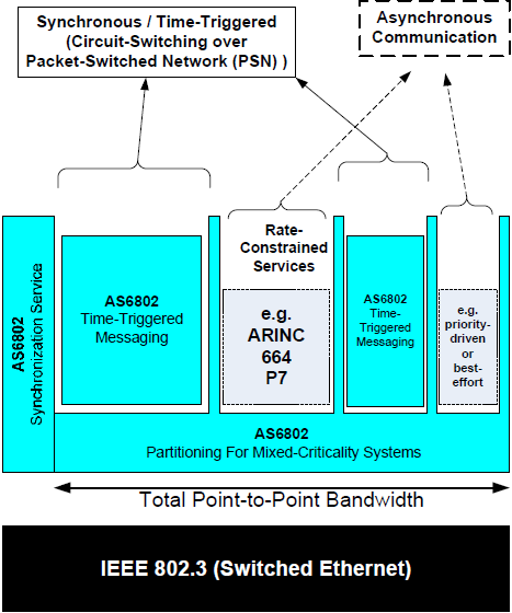 Figure 4-5: Traffic Partitioning
Network Level
Network Level Overview
A Time-Triggered Ethernet network is a Switch Ethernet based network - star topology - composed of End-Systems, Switches and links. End-Systems are the sources and destinations of the Ethernet packets and the Switch routes the packets according to a pre-established TTE configuration.
As an example, an on-board avionics computer composed of a micro-processor with a TTE communication controller interface is an End-System, the physical connections between the End-Systems are the links and the Switches provide the means for passing frames between the End-Systems. The links are connected to the communication ports of the End-Systems and Switches.
Figure 4-6 illustrates a basic switched communication network composed of two End-Systems and one Switch. The End-Systems have one full duplex communication port which is connected via a link to a communication port of the Switch. Depending on the fault tolerance needed, an End-System supports a given number of ports (up to three for dual fault-tolerance). The Switch in the example represented below has two communication ports.
 Figure 4-6: Network Communication Channel
An example network comprising several End-Systems and Switches is illustrated in Figure 4-6. Switches are connecting multiple End-Systems with each other and provide a means of switching packets from one End-System to one of many other possible End-Systems. Switches can also be cascaded to a larger network allowing the connection of much more End-Systems.
 Figure 4-7: A TTE example network
Packets can be transferred from one End-System to another through one or more Switches. The frames exchanged by the End-Systems and forwarded by the Switches are fully compliant to the [IEEE 802.3] frame layout.
An example network comprising several End-Systems and Switches is illustrated in Figure 4-7. This figure is for illustrative purposes and does not show a practical network. Packets can be transferred from one End-System to another through one or more Switches.
 Figure 4-8: Full Duplex Links
In switched Time-Triggered Ethernet the links are full duplex which means that sending and receiving of all traffic classes (TT, RC and BE) is possible at the same time as illustrated in Figure 4-8.
The frames exchanged by the End-Systems and forwarded by the Switches are fully compliant to the [IEEE 802.3] frame layout as defined in Figure 4-4.
Message Processing at the Switch
TTEthernet uses store and forward switching which means that the messages are fully received by the Switch and are then be checked for consistency, timing, frame layout, CRC, … until they are placed into the dedicated output queue.
A message conflict (whatever nature) can cause a delay of a message transmission until the transmission resource (port/link) becomes free. The pending messages are buffered, and their transmission is deferred. A message delay has different impacts on different traffic classes:
Best-Effort (BE): does not have any timing guarantees
Rate-Constrained: Introduce a jitter
Time-Triggered: delays a frame, frame can be received outside the receive window
Possible scenarios are:
Simultaneous TT-TT message conflict
Correct configuration schedules ensure that such message conflicts do not exist.
Simultaneous RC-RC message conflict
Priority mechanisms resolve the conflict.
Among the same priority: internal priority level based on source port number.
Simultaneous TT-RC message conflict
Priority mechanisms resolve the conflict.
Simultaneous TT-BE or RC-BE message conflict
TT or RC over Best-Effort
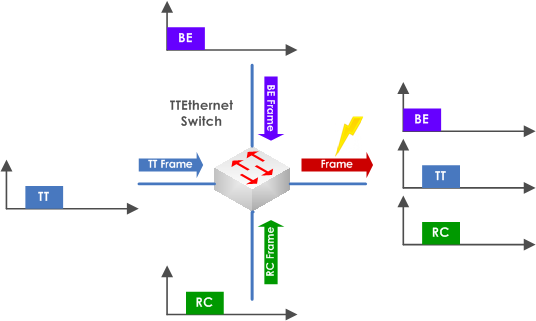 Figure 4-9: Message Processing at the Switch
In case an Ethernet frame is processed on the dedicated Switch port and a Time-Triggered send windows is dispatched as illustrated in Figure 4-9 there has to be a defined strategy for processing these two frames using the shared physical media.
The three different possible mechanisms are described below:
Preemption
Shuffling
Media Reservation
Preemption
Preemption is one of the above-mentioned mechanisms to allow high-priority frames to preempt low-priority frames in order to reduce the delay of a message transmission (see Figure 4-10). These delays introduce a jitter at runtime, which can negatively affect the system behaviour. The resulting jitter value caused by lower priority frames is always have to be considered in the scheduling algorithm and system design.
If a Time-Triggered Ethernet device is busy with the transmission of an outgoing dataflow with a low-priority frame (Best-Effort frame), it can be necessary to abort the transmission of this low-priority frame. A key characteristic of the preemption policy is that aborted transmissions are discarded. The Switch abort the transmission of the low-priority frame and mark it as invalid that the receiver discards the frame after receiving.
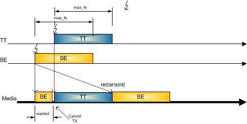 Figure 4-10: Preemption
Shuffling
The shuffling mechanism allows Best-Effort and Rate-Constrained frames passing the Switch also in case a Time-Triggered frame is scheduled (see Figure 4-11). In such a scenario the Time-Triggered frame can be delayed by a maximum Ethernet frame or rate constrained frame (1518 bytes @ 100 Mbps 124 µs). This known delay adds to the jitter and is considered in the scheduling steps of the configuration tool. The latency of a Time-Triggered frame can get increased because of the shuffling mechanism, but the jitter gets bounded and is not accumulate over multiple Switches. The Switch where shuffling occurs then forwards the Time-Triggered frame to the next Switch where the Time-Triggered frame is sent according to the sending window of this frame. Therefore, the dynamic delay value of this Time-Triggered frame does not accumulate over multiple Switches. Due to known delay values on the physical link the shuffling method allows to properly schedule Time-Triggered frames and allocate bandwidth for Rate-Constrained frames beforehand. As a result, this ensures all traffic classes can coexist in a network but reduces the available bandwidth for Time-Triggered traffic.
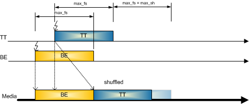 Figure 4-11: Shuffling
Media Reservation
Media reservation reserves a window of a maximum Ethernet frame (configurable) before a Time-Triggered frame is sent (see Figure 4-12). This mechanism does not allow frames with a lower priority to delay higher priority frames. Since the schedule point in time of the Time-Triggered frame is well known reserving a window in front of these frames is a matter of free scheduling resources which means that all media reservation windows need to have configured scheduling points. Depending on the used frame sizes this method can guarantee short latencies for Time-Triggered traffic but with implications to Best-Effort and Rate-Constrained traffic. By increasing the bandwidth utilization together with media reservation, the likelihood of losing low-priority frames gets increased.
Media reservation completely prevents the sending of low-priority frames delaying the scheduled Time-Triggered frame, but at the expense of bandwidth. The mechanism can be used to send scheduled Time-Triggered frames in a row, without lower-priority traffic interference.
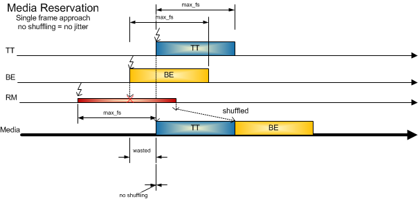 Figure 4-12: Media Reservation
In a summary, preemption is a mechanism that allows high-priority frames to preempt low-priority frames to reduce jitter of high-priority frames during runtime. A low priority preempt frame gets discarded by the receiver. Shuffling adds a bounded jitter to high-priority frames and is included in the scheduler algorithm, because of a maximum sized low-priority frames. The bounded jitter is known and does not accumulate over multiple Switches. Media reservation is a mechanism to prevent low-priority frames delaying high-priority frames by reserving bandwidth just before scheduling windows of high-priority frames. This allows to send high-priority frames in a row without a low-priority frame interference.
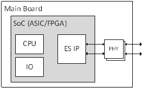
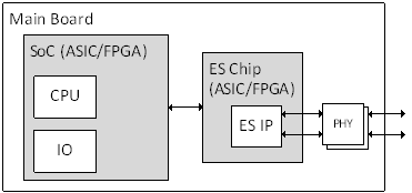
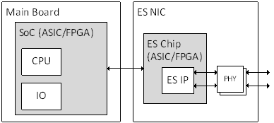
Time-Triggered Ethernet Network Building Blocks
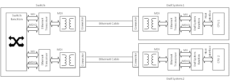 Figure 4-13: Network Building Blocks
A more detailed picture of the building blocks of a Time-Triggered Ethernet network is illustrated in Figure 4-13. The building blocks covered within this standard are:
Switch consisting of:
Switch function (digital part)
Ethernet transceiver (mixed signal part)
Connectors
End-System consisting of:
End-System function (digital part)
Ethernet Transceiver (mixed signal part)
Connectors
Cabling/Harness:
As an example, a few pictures of the building blocks of a Time-Triggered Ethernet network is shown in Figure 4-14.
|
|
|
|
Figure 4-14: Network Building Blocks Examples
Virtual Link
The concept of virtual links is used for critical traffic which means Time-Triggered and Rate-Constrained.
A Virtual Link (VL) provides the possibility to partition one physical link into multiple virtual links providing some additional quality of service to standard Ethernet [IEEE 802.3] as defined in [ARINC 664 part 7]. Each transmit VL can only be assigned to 1 End-System (ES), and an End-System is only allowed to transmit on assigned VLs.
The same receive VLs, however, can be assigned to several ESs meaning that these can be eavesdropping on the same data.
 Figure 4-15: Virtual Link
A Virtual Link is a conceptual communication object, which has the following properties:
A Virtual Link defines a logical unidirectional connection from one source End-System to one (unicast) or more (multicast) destination End-Systems, shown in Figure 4-15.
Each Virtual Link has a dedicated maximum bandwidth. This bandwidth is allocated by the System Integrator by using the configuration tools.
The End-System should provide logical isolation with respect to available bandwidth among the Virtual Link(s) it supports. Regardless of the attempted utilization of a VL by an application, the available Bandwidth on any other VL is unaffected.
For each Virtual Link, the End-System should maintain the ordering of data as delivered by an application, for both transmission and reception (ordinal integrity).
The End-System communication stack should guarantee in transmission the allocated bandwidth of each Virtual Link regardless of the attempted use of Bandwidth by other Virtual Links, in order to preserve segregation between partitions at the network level.
Virtual Links are used for the Critical Traffic, which means Time-Triggered and Rate Constraint (this means also for PCFs).
Time-Triggered Traffic Policing
Time-Triggered traffic requires to schedule all messages in the network. These messages are defined off-line with a corresponding tool which assigns a transmitting period at the End-System and an Acceptance Window at the Switch to guarantee a well-defined latency and minimal jitter in the system.
At the output of the End-System, the flow of frames associated with a particular Virtual Link is characterized by the transmitting period.
The Switch checks for all incoming frames the acceptance window associated with a particular Virtual Link. A Switch forwards all received frames based on a per-port forwarding schedule to ensure at the receiving End-System and well defined latency and minimal jitter.
Rate-Constrained Traffic Policing
Rate-Constrained traffic works with bandwidth reservation for defined messages. These messages are defined off-line with a corresponding tool which assigns a bandwidth allocation gap (BAG) and a jitter for each of them.
At the output of the End-System, the flow of frames associated with a particular Virtual Link is characterized by the following two parameters:
Bandwidth Allocation Gap (BAG) and
Jitter.
If the frames experienced no jitter from the scheduler, the BAG represents the minimum time interval between the first bits of two consecutive frames from the same VL, as illustrated in Figure 4-16.
 Figure 4-16: Bandwidth Reservation
Each frame has to wait until the dedicated BAG has been reached until it can be sent.
If the frames experience jitter from the scheduler, the jitter parameter is used to ensure the passing of the frames through the network. A description of this mechanism is given in [ARINC 664 part 7] § 4.1.1.3.
Clock Synchronization
Time-Triggered Ethernet is an extension of the traditional Ethernet standard, with additional services that guarantee reliable, deterministic delivery of time-critical messages.
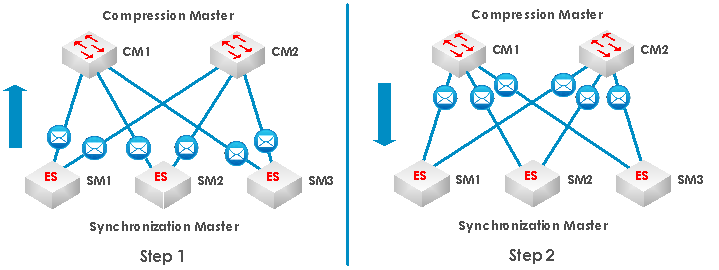 Figure 4-17: Time-Triggered Ethernet two step clock synchronization algorithm
End-System and Switches define physical components in the Time-Triggered Ethernet network and for the clock synchronization algorithm of Time-Triggered Ethernet three different roles are defined:
Synchronization Master (SM),
Compression Master (CM), and the
Synchronization Client (SC).
For simplicity we assume a network consisting of three End-Systems, two Switches and two redundant channels, as shown in Figure 4-17. Furthermore, End-Systems implement the SM role and the CMs are realized in the Switches. SCs are only passively synchronizing to the time base as maintained by the SMs and CMs. In the clock synchronization algorithm SMs and CMs inform each other about their current state of their local clock by exchanging Protocol Control Frames (PCF).
In Time-Triggered Ethernet the clocks are synchronized in two steps. In the first step, the SMs send PCFs to the CMs. The CMs extract from the arrival points in time of the PCFs the current state of their local clocks and execute a first convergence function, the so-called compression function. The result of the convergence function is then delivered to the SMs in form of new PCFs (the compressed PCFs). In the second step the SMs collects the compressed PCFs from the CMs and execute a second convergence function.
Time-Triggered Ethernet requires an inconsistent-omission failure model for the CMs. This means that a faulty CM is able to arbitrarily accept and reject PCFs from the SMs and can also decide to which SMs it sends the compressed PCF and to which not. Babbling idiot failures of the CM are excluded by the design of the CM as self-checking pair and a CM cannot fail arbitrarily. The SMs, on the other hand, can fail arbitrarily, and in particular, they can start to babble PCFs. The CMs implement a central guardian functionality that ensures that only one PCF per SM is used per re synchronization cycle. Though, in the worst case, we assume that the clock value provided by a faulty SM can be arbitrary.
First Step Convergence: Compression Master (CM)
The CMs collect the current states of the local clocks of the SMs. At the beginning of each convergence function the CM checks whether the number of bits set in the fields of unsynchronized PCF frames is above a configurable acceptance threshold. We denote these values by , where and assume that the values are sorted in increasing order. To minimize the impact of the faulty SMs Time-Triggered Ethernet uses a variant of the fault-tolerant median to calculate the new “compressed" clock. Following rules define the compressed clock depending on the number of SM clock values received.
One SM clock:
Two SM clocks:
Three SM clocks:
Four SM clocks:
Five SM clocks:
More than five SM clocks: average of the largest and the smallest clocks, where is the number of faulty SMs to be tolerated.
The compressed clock is delivered back to the SMs in a new "compressed" PCF and the SMs are able to read the compressed clock value from the arrival point in time of the compressed PCF. In addition to the compressed clock value, the CMs also generate a membership vector . Each position in this vector is assigned to one and only one SM. The CMs set the bit of a SM, if the respective SMi has provided a local clock value and clear the bit otherwise. The CMs transmit the vector in the payload of the compressed PCF. The self-checking pair design of the CM guarantees that the compressed clock and the vector are consistent. Hence, the design prevents a faulty CM to set an arbitrary number of bits in .
Second Step Convergence: Synchronization Master (SM)
In the second step of the clock synchronization algorithm, the SMs receive the compressed PCFs, extract the compressed clock values from them, and correct their local clocks. In the fault-free case each SM receives exactly one compressed PCF per CM from which it extracts the compressed clock values , where and we assume the values sorted in increasing order. Under the assumption of one CM per channel and up to three channels maximum, the convergence function has to cover following three cases:
One CM clock:
Two CM clocks:
Three CM clocks:
In the case of a faulty CM, a SM can receive at maximum one compressed PCF per CM (as the faulty CM can decide not to send its compressed PCF to some SMs). Furthermore, a SM only uses a compressed PCF in the convergence function as described above if the field has at least accept threshold of bits set. Accept threshold is calculated as follows:
Current max = maximum of bits set in the field of any compressed PCF
Accept threshold = current max minus the allowed number of faulty SMs
The SM discards a compressed PCF that has less than accept threshold bits set in the field. This mechanism ensures that a SM excludes compressed PCFs that represent relative low numbers of SM clocks.
The vector is also used in other Time-Triggered Ethernet algorithms such as clique detection or start-up as well as in network configurations that use more than one CM per channel. For the analysis of the clock synchronization algorithm the description above is sufficient.
Unsynchronized Operation (Start-Up or Re-Start)
During unsynchronized operation, as for example during a coldstart or restart of the TTEthernet network, the Synchronization Masters transmit dedicated Protocol Control Frames, that are coldstart and coldstart acknowledge frames. The Compression Masters collect the coldstart and coldstart acknowledge frames and decide based on this input and their current state in the Compression Master protocol state machine whether to send coldstart or coldstart acknowledge frames themselves back to the Synchronization Masters and Synchronization Clients.
The Compression Master can be configured in two ways depending on whether the Synchronization Masters in a system are configured as high-integrity devices or not. When the Synchronization Masters are designed as high-integrity devices the Synchronization Master failure mode is restricted. TTEthernet allows then to tolerate a faulty Synchronization Master and a concurrent fault of a Compression Master at the same point in time. When the Synchronization Masters are designed as standard-integrity devices, the Synchronization Masters can fail in an arbitrary failure mode. In this case (standard integrity) TTEthernet tolerates either the failure of Synchronization Masters or the failure of Compression Masters, but not both at the same point in time.
A CM during start-up sequence with standard integrity synchronization masters dispatch coldstart frames when the compression master is in an unsynchronized state, and blocks coldstart frames in all other states.
A CM during start-up sequence with high-integrity synchronization masters, dispatch:
All coldstart frames, only when the compression master is either in CM_UNSYNC state, CM_Wait_4_Cycle_Start, or
CM_TENTATIVE_SYNC state and it discards coldstart frames received in other states as specified in [SAE AS6802] §9.4.
All received coldstart acknowledge frames.
All received integration frames as compressed integration frames.
An example of an integration PCF frame exchange between a compression master and two synchronization master is shown in Figure 4-18.
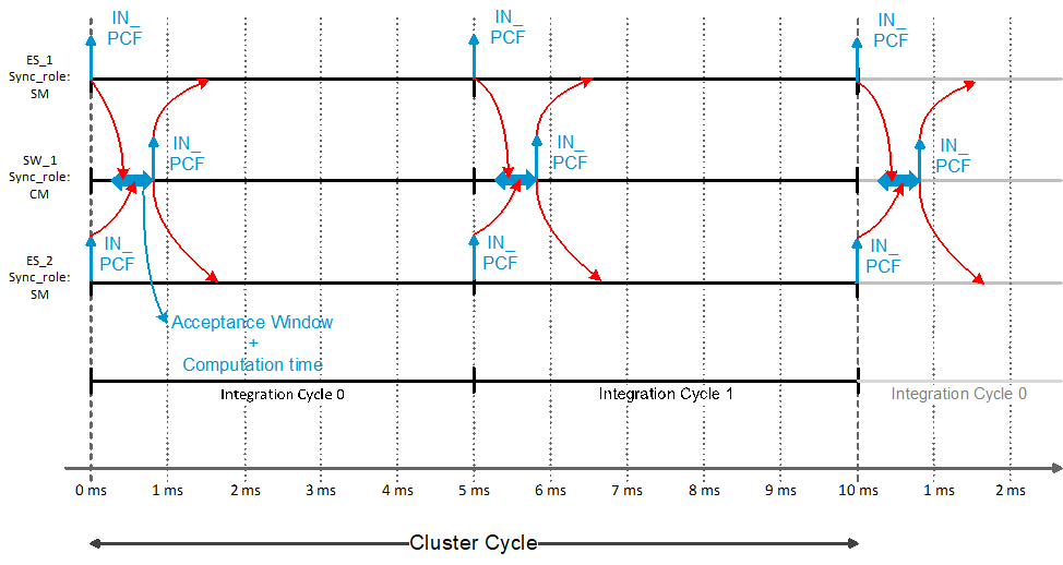 Figure 4-18: Example of an integration PCF Frame exchange
To tolerate a single Byzantine fault in the clocks of the synchronization masters there is a need for at least 4 SMs because of the Byzantine theorem. For two fault tolerance there is a minimum of 7 SMs needed since it allows to tolerate any Byzantine two faults of clocks of the synchronization masters.
More details about the clock synchronization can be found in the Time-Triggered Ethernet standard [SAE AS6802].
Redundancy Concept
Introduction
End-Systems communicate over multiple independent and redundant networks such that data flows are protected against the failure of any network component such as a link or a Switch. The effect of this is to protect communication between End-Systems against the loss of one complete network.
 Figure 4-19: Redundancy Communication
The Figure 4-19 shows the basic concept for network redundancy. The redundancy scheme is operated on a per Virtual Link basis. A transmitting End-System and a receiving End-System communicate via a specific Virtual Link. This Virtual Link can be configured as TT or RC traffic. Depending on the configuration of the End-System the Virtual Link is sent at a defined point in time if it is a TT Virtual Link or can be send immediately (depending on the priority sending buffer) if it is a RC-Virtual Link. Depending on the configured redundancy degree, the communication controller duplicates or triplicates the Virtual Link on the redundant channels.
For critical traffic the sending application is unaware of the underlying network redundancy, and a simple interface can be built between the communications controller and the host that utilize the network service.
The frame routing between the host and the physical ports can be configured so that frames can be send on one, two or all three ports. Upon reception, it is possible to configure no redundancy management or an algorithm in the communication controller which uses a “First Valid” policy. This means that the first frame to be received from either network is accepted and passed up to the receiving host.
As the flow of frames given in Figure 4-20 below indicates, RM (Redundancy Management) is placed after IC (Integrity Checking). Under fault-free network operation, the controller just passes on the frames that it has received from a network on to the RM. The redundancy management is merely to eliminate frames that are redundant copies of frames that it has already passed on to the host.
 Figure 4-20: Redundancy Management at the Receiver
The Integrity Checking has the task of eliminating invalid frames. In case of RC traffic, it checks the incoming frames for any faults based on their sequence number to eliminate stuck frames or single abnormal frames and reducing the impact of a babbling Switch. A description of this mechanism is given in [ARINC 664 part 7] § 3.2.6.2.1.
TT traffic
The sending host prepares the data and passes it to the communication controller which, depending on the redundancy degree duplicates/triplicates the data and adds the Ethernet header information to it. A sequence number is not needed since the traffic is scheduled based on the global fault-tolerant time base and therefore the sending order cannot change.
RC traffic
The sending host prepares the data and passes it to the communications controller. Here a sequence number field is added to each frame, and the sequence numbers are incremented on each successive frame. The sequence number is added to enable the receive function to reconstruct a single ordered stream of frames without duplication before delivery to the receiving application. The “First Valid” frame that is received from the network with the next valid sequence number gets passed up to the receiving host. If a frame with the same sequence number is received it is simply discarded.
Failure-modes
Time-Triggered Ethernet is designed to tolerate either the fail-arbitrary failure mode of an End-System or the fail-inconsistent-omission failure mode of a Switch. The Switches in Time-Triggered Ethernet network can be configured to execute a central bus guardian function. The central bus guardian function ensures that even if a set of End-Systems becomes arbitrarily faulty, it masks the system-wide impact of these faulty End-Systems by transforming the fail-arbitrary failure mode into an inconsistent-omission failure mode. The central bus guardian function is ensured by the traffic policing, specified in Clause 6.2.6 Switch Traffic Policing. The arbitrarily faulty failure mode also includes the babbling-idiot behaviour.
Fail arbitrary failure mode:
A device that fails arbitrarily can generate messages with random contents at arbitrary points in time on arbitrary selection of outputs.
Fail inconsistent-omission failure mode:
A faulty device can arbitrarily classify a subset of received messages as correct, while classifying the remaining messages (potentially correct) as incorrect
Network Architecture
Overview
Introduction
A TTE network architecture is a Switched-based implementation, or “star topology”, designed for real-time critical application, in which all End-System nodes (SM and SC) are individually connected to a central connection point: a TTE Switch (CM or SC).
This Clause defines the different types of architectures which can be implemented in a TTE network:
Single Channel Network Topology
Dual Channel Network Topology
Triple Channel Network Topology
Mixed Channel Network Topology
Network Topology composed of Standard Ethernet node
Single Channel Network Topology
A TTE single network is a network in which only one channel is used for the data communication between the nodes of the network, as illustrated in the following example composed of two End-Systems.
 Figure 5-1: Single Channel Network Topology
This network architecture involves a single point of failure of the devices over the network and the communication can be broken in case of event of a network failure (broken cable or connector, Switch or End-System failure).
Single network topology can be composed of one Switch or several cascaded Switches as illustrated on Figure 5-1 and Figure 5-3.
In case the network is composed of one Switch, the Switch takes the Compression Master role with regards to the synchronization while Synchronization Masters can be supported by any of the End-Systems in the network. Single network topology requires that minimum one Synchronization Master is active within the TTE network.
 Figure 5-2: Single Channel Network Topology – without cascaded Switches
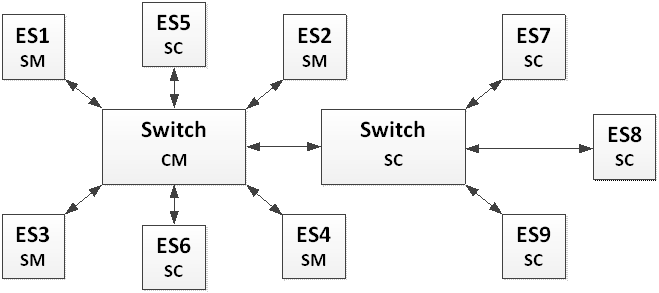 Figure 5-3: Single Channel Network Topology – with cascaded Switches
Dual Channel Network Topology
A TTE dual redundant network is a network composed of two redundant Links dedicated for the data communication between the nodes of the network as illustrated in the following example through an example composed of two End-Systems.
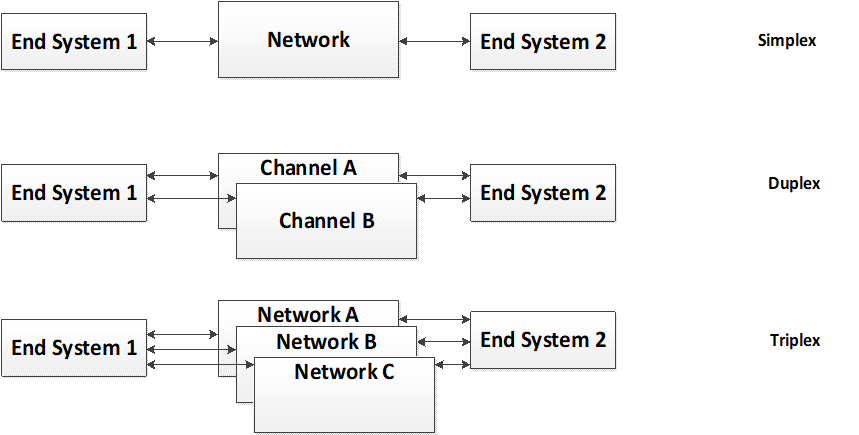 Figure 5-4: Dual Channel Network Topology
This TTE network architecture type enables covering space application requiring one-fault tolerant architecture (1FT) at system level. Each VL is transmitted in hot redundancy (at the same point in time) on both channels.
Dual network topology can be composed of one Switch or several cascaded Switches per channel. In case the network is composed of two redundant Switches, these Switches take the Compression Master role and Synchronization Masters can be performed by any of the End-Systems part of the network. Dual Redundant network with One Fault Tolerant requirement requires that minimum four Synchronization Masters are active within the TTE network.
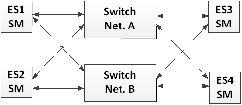 Figure 5-5: Dual Channel Network Redundancy without cascaded Switches
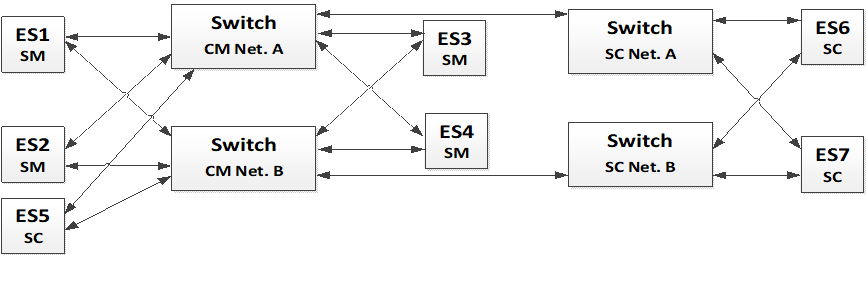 Figure 5-6: Dual Channel Network Redundancy with cascaded Switches
Triple Channel Network Topology
A TTE triple redundant network is a network composed of three redundant Links dedicated for the data communication between the nodes of the network. It is illustrated on the following figure through an example composed of two End-Systems.
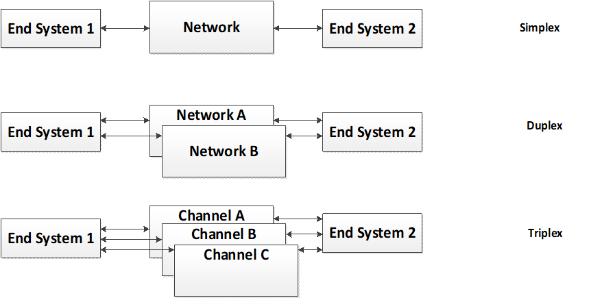 Figure 5-7: Triple Channel Redundant Network Topology
This TTE network architecture type enables covering space application requiring two-fault tolerant architecture (2FT) at system level. Each VL is transmitted in hot redundancy to the three networks.
Triple network topology can be composed of one Switch or several cascaded Switches per channel as illustrated here-after on figure 9 and figure 10. In case the network is composed of three redundant Switches, these Switches take the Compression Master role with regards to the synchronization while Synchronization Masters can be performed by any of the End-Systems part of the network. Triple Redundant network with Two Fault Tolerant requirement requires that minimum seven Synchronization Masters are active within the TTE network.
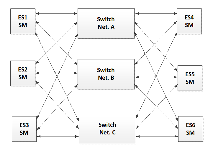 Figure 5-8: Triple Channel Network Redundancy without cascaded Switches
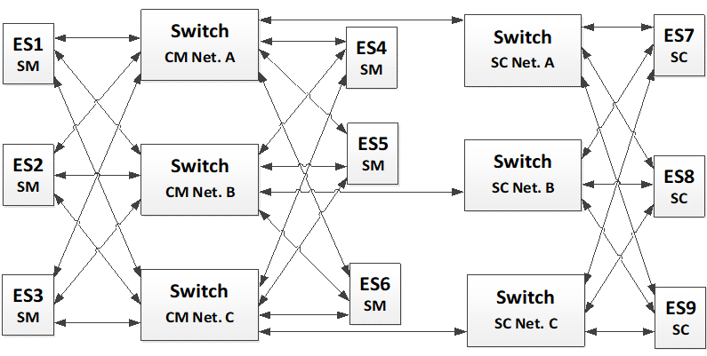 Figure 5-9: Triple Channel Network Redundancy with cascaded Switches
Mixed Network Topology
A TTE mixed network topology is a network composed of redundant or single Links dedicated for the data communication between the nodes of the network. It is illustrated on the following figure through an example composed of multiple End-Systems.
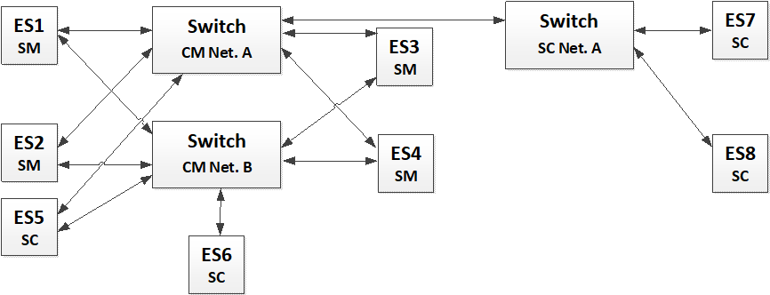 Figure 5-10: Mixed Architecture
This TTE network architecture type allows to combine applications where redundancy is needed as well as non-redundant ones. This means that the synchronization in the redundant part can be configured to be single fault-tolerant with e.g. 4 SMs as illustrated in this example connected to a non-redundant part of the cluster which is synchronized to the same time-domain but only support a single channel non-redundant architecture. This setup illustrates the configurability of the TTE network allowing to support different kind of architectures.
Multiple Networks Topology
Multiple Network topologies are combined clusters consisting of two or more individual networks. Each of these clusters is able to work self-sustained but in a combination with others the clusters are able to provide an extended functionality. A cluster is defined as an independent distributed avionics system which is self-sustained and provides a defined interface to the outside world.
This Clause describes the multiple networks topology approach combining multiple independent cluster based on TTEthernet to a single network. It further describes the cluster concept, the TTEthernet technology features provided to support these applications and how such an integration can be implemented.
In this Clause we assume that each of the cluster is based on a TTEthernet network or at least offers a TTEthernet interface allowing to interface to another system.
The multiple networks topology is defined such as different independent cluster having their own communication network with use-cases integrate into one cluster to fulfil their mission requirements. This means that two independent data network handling different control- or management-data join and leverage the function from each other at least partly by exchanging data over the joint links.
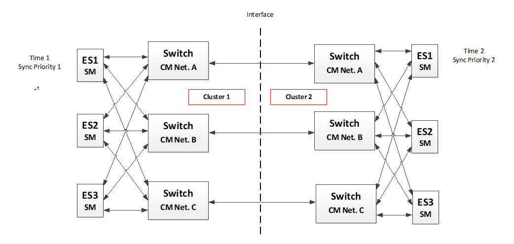 Figure 5-11: Multiple Networks Topology
Each of the above described cluster has a data network providing different quality of services to the application like fault-tolerant global time base, deterministic data transfer, redundancy management, network diagnostics and network management.
If these networks are connected, the goal is to keep as much services as possible available to allow an operation of the resulting coupled system without decrease of the quality of service or even increase the capability of some functions by combining the two data networks. This allows to have multiple clusters which are able to be controlled or use services from another cluster. The data of one cluster can selectively be used in the other cluster and therefore the interface between these clusters needs to be specified according to the services needed.
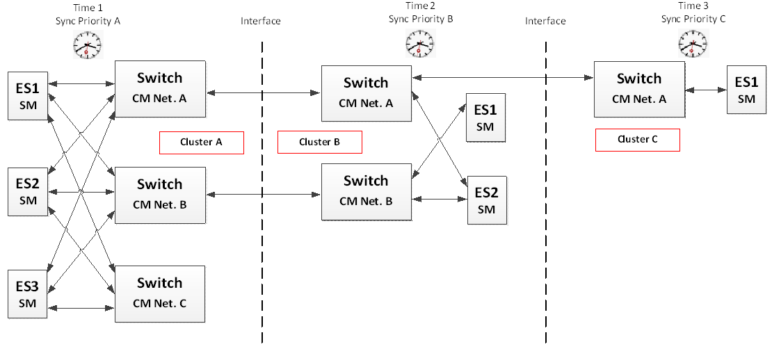 Figure 5-12: Synchronization priority assignment recommendation
Compatibility with standard Ethernet Network
The TTE cluster topologies are Ethernet compatible and therefore interoperable with Best-Effort nodes where Best-Effort traffic class is used for the communication as illustrated in Figure 5-13 composed of seven nodes:
3 Standard-Ethernet End-Systems
3 TTEthernet End-Systems
1 TTEthernet Switch
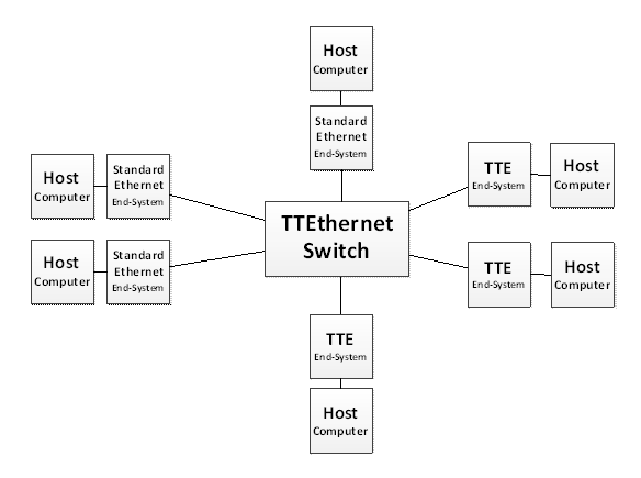 Figure 5-13: Time-Triggered Ethernet topology composed of standard Ethernet nodes
Time-Triggered Ethernet End-Systems are connected via Time-Triggered Ethernet Switches for Time-Triggered, Rate-Constrained and Best-Effort communication. Standard-Ethernet nodes can be connected to both Time-Triggered Ethernet End-Systems and Time-Triggered Ethernet Switches. TTEthernet End-Systems can communicate by using the Best-Effort traffic class and therefore be connected to Ethernet or TTEthernet Switches or End-Systems.
Network Topology Requirements
Single Network Topology
ECSS-E-ST-50-16_1490001TTEthernet network topology shall be at least one of the following types:
- Single channel
- Dual channel
- Triple channel
- Mixed
ECSS-E-ST-50-16_1490002All Time-Triggered End-System shall be of either SM or SC type as specified in [SAE AS6802].
ECSS-E-ST-50-16_1490003All Time-Triggered Switches shall be of either CM or SC type as specified in [SAE AS6802].
ECSS-E-ST-50-16_1490004An End-System of SC type shall implement the synchronization client functionality as specified in the [SAE AS6802] standard §9.3.
ECSS-E-ST-50-16_1490005An End-System of SM type shall implement the synchronization master functionality as specified in the [SAE AS6802] standard §9.2.
ECSS-E-ST-50-16_1490006A Switch of CM type shall implement the compression master functionality as specified in the [SAE AS6802] standard §9.4 & §9.5.
ECSS-E-ST-50-16_1490007A Switch of SC type shall implement the synchronization client functionality [SAE AS6802] standard §9.3.
ECSS-E-ST-50-16_1490008A TTEthernet network shall be composed of at least (as specified in [SAE AS6802] §4.2): - 1 SM and 1 CM for Single network Topology (No Fault Tolerant)
- 4 SM and 2 CM for Duplex network Topology (Single Fault Tolerant architecture)
- 7 SM and 3 CM for Triplex network Topology (Dual Fault Tolerant architecture)
In order to tolerate Byzantine faults in a distributed system Nodes are required.
ECSS-E-ST-50-16_1490009The TTE network shall be usable as a conventional [IEEE 802.3] Ethernet network at least at MAC level.
Without the need of synchronization.
ECSS-E-ST-50-16_1490010In all fault-tolerant network setups the respective fault hypothesis shall remain valid so that:
- For 1FT the network is able to tolerate a single fault of any TTE network element in the network.
- For 2FT the network is able to tolerate any 2 faults of any TTE network element in the network.
- 1 Since the reliability depends typically on the mission/application, different hybrid models are possible. However, the basic fault-tolerance which is also described in the [SAE AS6802] standard §3.3.1 is 0FT, 1FT and 2FT with a certain configuration of the parameters. This requirement covers arbitrary faults of any End-System as well as inconsistent omissive faults of any Switch in the network.
- 2 Inconsistent omissive faults is when a node arbitrarily classifies a subset of received messages as correct while classifying the remaining messages, potentially correct, as incorrect.
ECSS-E-ST-50-16_1490011If the SM is connected to the CM via a TT Switch, then this Switch shall be transparent with regards to PCF frames.
Transparent means, that the TT Switch needs to update its transparent clock in PCF frames passing this Switch as described in [SAE AS6802] §5.1.
Multiple Networks Topology
ECSS-E-ST-50-16_1490012A TTEthernet multiple network topology shall at least contain two separate networks of the following topologies:
- Single channel topology
- Dual channel topology
- Triple channel topology ECSS-E-ST-50-16_1490013In a multiple network topology, the following clock synchronization parameters shall be equal between separate cluster:
- Integration Cycle Duration
- Cluster Cycle Duration ECSS-E-ST-50-16_1490014In a multiple networks topology, for rate constrained traffic the following parameters shall be equal between separate clusters for each VL:
- BAG
- Jitter ECSS-E-ST-50-16_1490015In a multiple network topology, each cluster shall have a unique synchronization priority.
The synchronization priority assignment is depending on the network topology of each cluster. It is recommended that clusters with three channels have higher priority than clusters with two channels as illustrated in Figure 5-12.
ECSS-E-ST-50-16_1490016If separate clusters are joined together, the synchronization master and client shall realize the host-interactive and autonomous modes of PCF filtering as specified in [SAE AS6802] §10.1.
ECSS-E-ST-50-16_1490017If separate clusters are joined together, the compression masters shall automatically synchronize to the higher priority PCFs received from the synchronization master.
ECSS-E-ST-50-16_1490018The transparent clock granularity between joined clusters shall be equal.
ECSS-E-ST-50-16_1490019The network synchronization precision between joined clusters shall be equal.
ECSS-E-ST-50-16_1490020The CT-Marker between joined clusters shall be equal.
ECSS-E-ST-50-16_1490021The Max Transparent Clock value between joined clusters shall be equal.
The Max Transparent Clock calculation includes all clusters
Device Services
Overview
This Clause specifies the requirements applicable to the Switch and End-System devices.
In this Clause the following OSI Layer Services are specified (see Figure 6-1):
Application Layer:
TFTP: for data loading and file transfer
SNMP: for network management
Transport Layer:
UDP: required for application layers TFTP, SNMP, and communication ports
TCP: is considered optional and not covered in this document.
Network Layer:
IP: IPv4 required by transport/application layers
ICMP: to be used for diagnostic and monitoring purposes or generated in response to errors in IP operations
Data Link:
[SAE AS6802]: as a Layer 2 Quality-of-Service (QoS) enhancement for TTE and for time synchronization
Ethernet MAC: based on [IEEE 802.3] and the [ARINC 664 part 2]
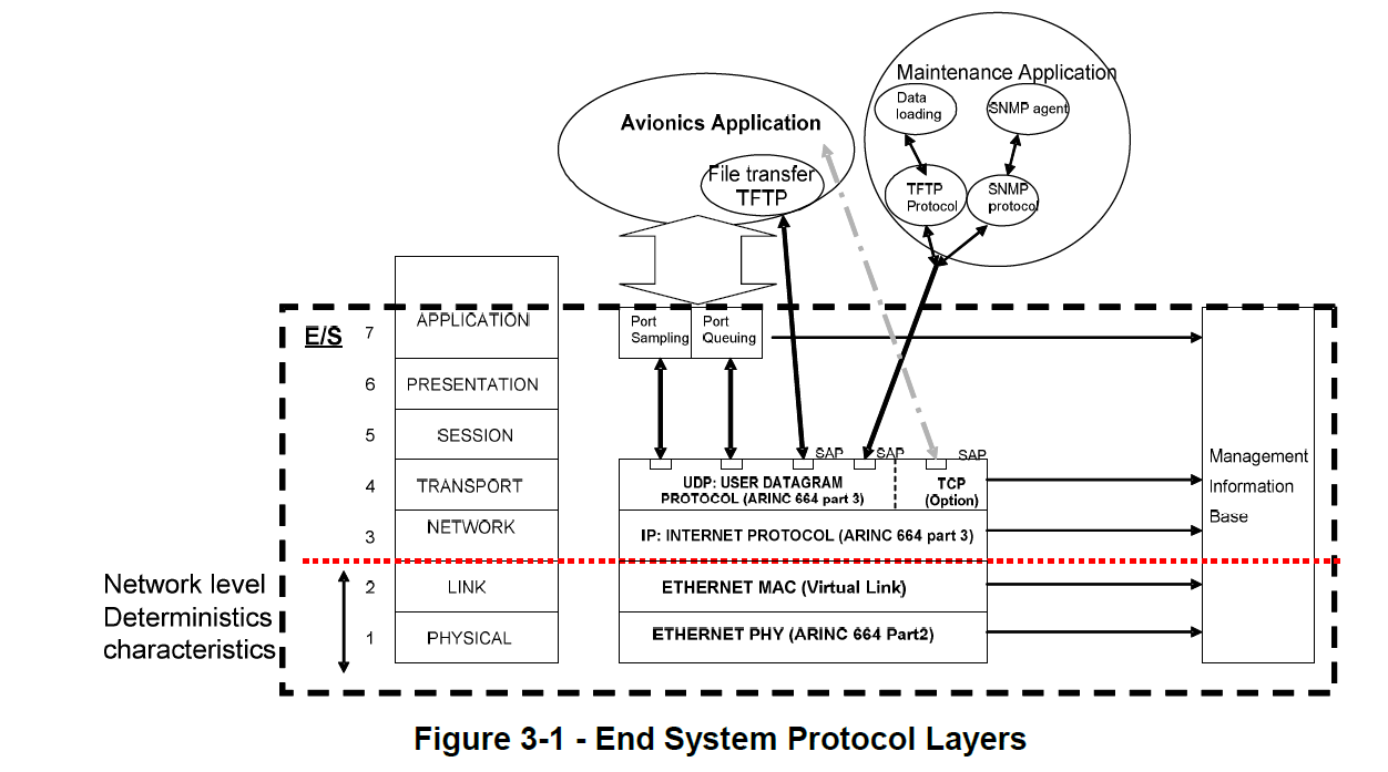 Figure 6-1: OSI Layer Services
Media Access Control (MAC) Sublayer
MAC sublayer functions
ECSS-E-ST-50-16_1490022The MAC sublayer functions shall be implemented according to [IEEE 802.3] § 1 4.2.3.
MAC Addressing
ECSS-E-ST-50-16_1490023A MAC destination address of a Critical Traffic frame shall have a unique 32-bit configurable Critical Traffic (CT-Marker) field for critical traffic (TT and RC) in a Time-Triggered Network.
In order to be compliant with the Ethernet standard, MAC group addresses is used to send frames from End-System to End-System(s). The CT-Marker field should follow the formatting as illustrated in Figure 6-2.
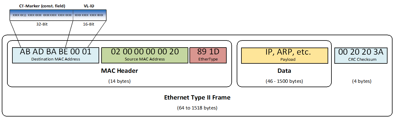 Figure 6-2: Destination MAC Address
ECSS-E-ST-50-16_1490024A Virtual Link shall be identified by the MAC destination address with a network unique CT-Marker and a Virtual Link Identifier (VLID).
Illustration is given in Figure 6-2.
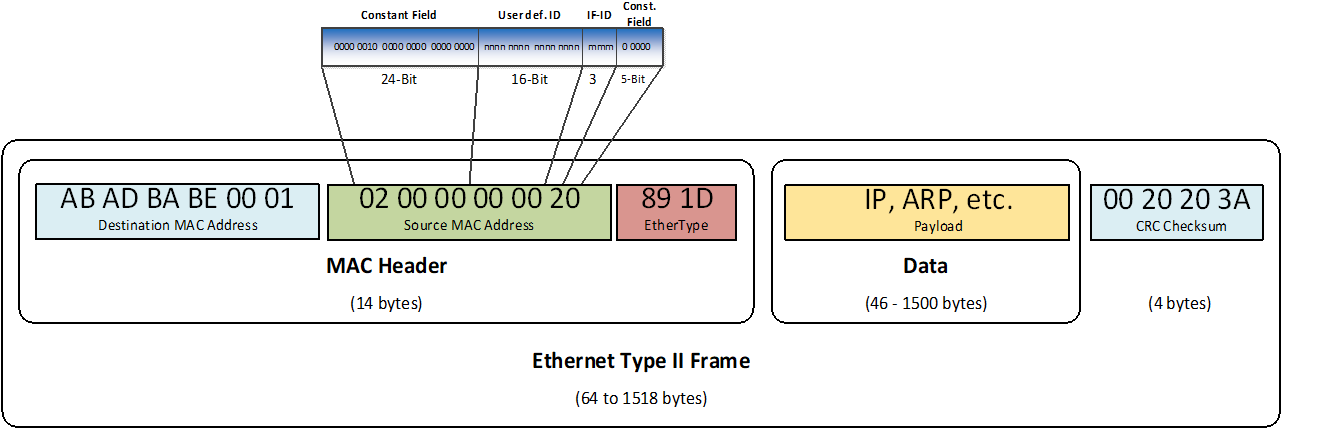 Figure 6-3: Source MAC Address
ECSS-E-ST-50-16_1490025The Constant field (24-Bit) of the source MAC address shall be set to “0000 0010 0000 0000 0000 0000”.
ECSS-E-ST-50-16_1490026The MAC Source address shall be an Individual and Locally Administered address compliant with [IEEE 802.3] § 3.2.4.
As illustrated in Figure 6-3.
ECSS-E-ST-50-16_1490027The Const. Field (5-Bit) of the source MAC address shall be set to “0 0000”.
As illustrated in Figure 6-3.
ECSS-E-ST-50-16_1490028The User defined ID (User def. ID) is a single 16-bit field that shall be used to give each addressable host on the network a unique MAC address.
This is defined by the network integrator who creates the configurations for the network. It provides additional information on the source of the message.
ECSS-E-ST-50-16_1490029The redundant frames transmitted on all ports shall always be the same except the MAC source address where different interface ID fields are assigned at each port and the FCS.
ECSS-E-ST-50-16_1490030The network on which a frame is transmitted shall be identified according to the Interface ID (IF-ID) field of the Ethernet MAC source address as defined in Table 6-1.
The Interface ID defined in Table 6-1 indicates to which redundant Time-Triggered Ethernet network the Ethernet MAC frame is transmitted.
ECSS-E-ST-50-16_1490031Table 6-1: Interface ID
|
Interface ID
|
Description
|
|
0 0 1
|
The Ethernet MAC frame is transmitted to network A
|
|
0 1 0
|
The Ethernet MAC frame is transmitted to network B
|
|
0 1 1
|
Not used
|
|
1 0 0
|
The Ethernet MAC frame is transmitted to network C
|
|
1 0 1
|
Not used
|
|
1 1 0
|
Not used
|
|
1 1 1
|
Not used
|
Traffic Classes
ECSS-E-ST-50-16_1490032Each network element supporting this standard shall implement the three traffic classes: Time-Triggered, Rate-Constrained and Best-Effort.
ECSS-E-ST-50-16_1490033The priorities of traffic classes shall be as following:
- Protocol control frame (PCF) has highest priority
- Time-triggered traffic (TT) has the second highest priority
- Rate-Constrained traffic (RC) has priority(s) in between TT and BE
- Best-Effort (BE) has the lowest priority
ECSS-E-ST-50-16_1490034PCF, TT, RC and BE traffic shall be sent according to their priority.
ECSS-E-ST-50-16_1490035In reception each network element should have at least two independent memory partitions one for Best-Effort and one for Critical Traffic.
This is an optional requirement to separate input memory partitions and allow in case of a babbling idiot behaviour to receive critical traffic on a faulty node.
ECSS-E-ST-50-16_1490036In transmission, each network element should have at least two independent memory partitions one for Best-Effort and one for Critical Traffic.
This is an optional requirement to separate output memory partitions allow in case of a babbling idiot behaviour to transmit critical traffic on a faulty node.
MAC Transmit
ECSS-E-ST-50-16_1490037Switch function without a compression master role shall not be able to generate PCF frames.
A Switch without a compression master role is only able to relay PCF frames.
ECSS-E-ST-50-16_1490038If a frame is discarded, a dedicated diagnostics counter shall be incremented to provide this information to the upper layers.
This counter allows to distinguish between sporadic or permanent errors
ECSS-E-ST-50-16_1490039A TT traffic shall be sent at defined scheduled points according to the synchronized time.
ECSS-E-ST-50-16_1490040If the End-System is not synchronized, only rate constrained frames and Best-Effort frames shall be transmitted.
ECSS-E-ST-50-16_1490041In case the MAC performs a clock correction, it shall adjust the time interval between the current schedule point and the next schedule point, by adding the clock correction value to this time interval.
ECSS-E-ST-50-16_1490042Frames shall be sent on the redundant ports simultaneously.
The delay between transmissions of the redundant frames is not specified but has an impact on the synchronization precision (refer to Clause 7.4).
ECSS-E-ST-50-16_1490043Redundant RC frames shall have the same sequence number.
MAC Receive
General
ECSS-E-ST-50-16_1490044At the successful receive of a MAC Frame, the MAC shall treat a valid MAC frame as specified in [IEEE 802.3].
Critical Traffic
ECSS-E-ST-50-16_1490045The MAC shall treat a valid MAC frame as Critical Traffic if the CT-Marker matches the CT-Marker entry of the Table 7-9.
ECSS-E-ST-50-16_1490046The MAC shall discard a valid MAC frame belonging to Critical Traffic if the VLID does not match any entry of the Table 7-6.
ECSS-E-ST-50-16_1490047The MAC shall discard a valid Critical Traffic frame if the MAC Frame Length is greater than the value configured for the maximum frame size.
If larger frames are sent, the bandwidth restrictions can be violated.
ECSS-E-ST-50-16_1490048Redundant TT frames shall be identified according to their destination MAC address (CT-Marker, VL-ID) and the respective receive window.
ECSS-E-ST-50-16_1490049The time-skew between the redundant instances of the TT frames shall be configurable.
ECSS-E-ST-50-16_1490050Redundant RC frames shall be identified according to their destination MAC address and the respective sequence number.
ECSS-E-ST-50-16_1490051The time-skew between the redundant instances of the RC frames shall be configurable.
ECSS-E-ST-50-16_1490052Depending on the configuration parameter, a configurable redundancy management unit shall forward the first valid frames to the host or forward all redundant frames to the host.
Switch Traffic Policing
ECSS-E-ST-50-16_1490053If the Switch is not synchronized, it shall discard all received Time-Triggered frames.
ECSS-E-ST-50-16_1490054The Switch shall discard a received frame which is policed to be Time-Triggered if the Switch holds a previous frame of the same VLID.
ECSS-E-ST-50-16_1490055In reception, if a TT frame is received outside its scheduled time window, the frame shall be discarded.
For the calculation of the acceptance window duration, refer to guidelines provided in Clause 7.5.8.
ECSS-E-ST-50-16_1490056The Switch shall discard all valid Time-Triggered frames stored inside the Switch and waiting for transmission in case of a Synchronization Loss.
ECSS-E-ST-50-16_1490057The Switch shall discard any valid Time-Triggered frames which frame length is greater than the MaxLength entry defined in Table 7-11.
The related diagnostics and status information counter are described in Clause 8.4.3.
ECSS-E-ST-50-16_1490058Traffic policing for RC traffic shall be in accordance with requirements specified in [ARINC 664 part 7] §4.1.1 and §4.2.2.
ECSS-E-ST-50-16_1490059In reception, if on a given port the Switch receives a frame with a VL-ID not consistent with the VL-IDs expected on this port, the frame shall be discarded.
The related diagnostics and status information counter are described in Clause 8.4.3
ECSS-E-ST-50-16_1490060If a PCF frame does not have a payload length of exactly 46 bytes, the frame shall be discarded as specified in [SAE AS6802] §4.6.
ECSS-E-ST-50-16_1490061A PCF frame shall include the actual integration cycle number as specified in [SAE AS6802] §4.6.
ECSS-E-ST-50-16_1490062A PCF frame shall include a membership vector of all synchronization master contributing to the synchronization protocol as specified in [SAE AS6802] §4.6.
ECSS-E-ST-50-16_1490063A PCF frame shall include the synchronization priority and synchronization domain as specified in [SAE AS6802] §4.6.
ECSS-E-ST-50-16_1490064A PCF frame shall include the transparent clock value as specified in [SAE AS6802] §4.6.
ECSS-E-ST-50-16_1490065In case the Switch is forwarding PCF’s, a PCF frame shall be discarded if the time interval between two consecutive PCF of the same VL-ID is outside the limit specified by the entries BAG and Jitter in the Output VL Table associated to this VL-ID.
- 1 The value for jitter depends on the precision.
- 2 The Switch Output VL Table is defined in Table 7-11.
ECSS-E-ST-50-16_1490066In case the Switch is forwarding PCF’s, the values for BAG shall be equal to the integration cycle.
ECSS-E-ST-50-16_1490067In reception, if a MAC frame is not correct, as specified in [IEEE 802.3], the frame shall be discarded.
Switch Transmit
ECSS-E-ST-50-16_1490068The Switch shall allow reserving the sending media for a defined CT-frame.
This is needed to ensure that TT frames are not delayed by other frames which are in the sending process when a TT frame is sent. The reservation of a window in front of a TT frame does not allow to process other frames within this window.
ECSS-E-ST-50-16_1490069If the following conditions are both true, the Switch shall start at a defined point in the Schedule Table:
- The Switch adjusts its local clock to the network time received via an integration PCF frame,
- The Switch adjusts its local integration cycle number with the integration cycle number contained in the integration PCF frame. ECSS-E-ST-50-16_1490070When the Switch finishes executing the last entry of the Schedule Table, the Switch shall restart with the first entry of the Schedule Table.
Switch Frame Routing
ECSS-E-ST-50-16_1490071The Switch shall support both of the following routing scheme:
- Static Best-Effort routing according to a static Best-Effort routing table as part of the configuration
- Dynamic Best-Effort routing according to a dynamic Best-Effort routing table created via address learning according to RFC 826
ECSS-E-ST-50-16_1490072CT-Frames shall be routed according to their VL-ID
ECSS-E-ST-50-16_1490073In case preemption is not used, a Switch shall not cause sending of incomplete frames because of a priority conflict on a sending port.
If a higher priority frame is sent at a dedicated port where a lower priority frame is in process, the low priority frame sending process cannot be interrupted.
ECSS-E-ST-50-16_1490074The Switch shall be able to perform independent frame routing on all ports at the same time with full line rate.
ECSS-E-ST-50-16_1490075The order of Rate-Constrained frames received on the same reception port and belonging to the same VLID shall be preserved on the transmission port.
Interoperability Specification
Overview
This Clause specifies the parameters of the implementation which are needed to achieve interoperability between the Switches and End-Systems developed according to this standard. This Clause specifies it for the implementation e.g. IP level and allows together with the Network Configuration Clause an integration of devices from different vendors into a complete network.
It further defines the network configuration parameters which are needed to create a configuration of the network and each device specifying e.g. senders, receivers, messages, time-constraints and redundancy constraints.
All these parameters are taken by the configuration tools as an input to derive the device specific configurations. Since not every device needs to be aware of the whole network configuration, these configurations only need to define the device related parameters to ensure the interoperability with the network. However, the network related device parameters need to be consistent to ensure a correct behaviour of the TT and RC traffic flows.
This Clause aims at specifying the parameters needed on the different layers (network and device) to ensure the interoperability within a network.
Figure 7-1 shows the interface between the tool creating the device specific configuration out of the network level specification which are used by the IP to perform the operation.
 Figure 7-1: Configuration Interface Tool – IP
Device Specification
Device Parameters Description
ECSS-E-ST-50-16_1490076The parameters which are used to ensure the interoperability between the nodes in the network for the Switch and the function shall be defined as per Table 7-1, Table 7-2 and Table 7-3.
These parameters are essential inputs for the creation of the configuration for the devices since it defines the performances of each of them within the network.
ECSS-E-ST-50-16_1490077Table 7-1: General Interoperability Parameter Table
|
Parameter
|
Description
|
|
CLOCK_SYNC_PRECISION
|
Clock synchronization precision
|
ECSS-E-ST-50-16_1490078Table 7-2: Switch Interoperability Parameter Table
|
Parameter
|
Description
|
|
SW_TT_TX_LENGTH
|
Frame length of the Time-Triggered frame to be sent
|
|
SW_TT_TX_PERIOD
|
Period of the Time-Triggered frame to be sent
|
|
SW_TT_TX_PHASE
|
Phase of the Time-Triggered frame to be sent
|
|
SW_SCHEDULE_GRANULARITY
|
Raster granularity in which the Time-Triggered frames can be placed for sending
|
|
SW_MIN_TT_TX_GAP
|
The minimum gap between two consecutive Time-Triggered frames to be transmitted
|
|
SW_TT_TX_MAX_JITTER
|
Maximum duration from synchronized state to the first bit placed onto the transmit line
|
|
SW_ TT_TX_FRAMES
|
Number of Time-Triggered frames the Switch is able to transmit
|
|
SW_NUM_TT_TX_PERIOD
|
Maximum number of different Time-Triggered periods a Switch supports for transmit
|
|
SW_LIST_TT_TX_PERIOD
|
List of Time-Triggered frame periods the Switch supports
|
|
SW_TT_RX_WINDOW_CHECK
|
Input policing for Time-Triggered frames supported by the Switch
|
|
SW_TT_RX_EXPECT_ARR_TIME
|
Expected arrival time of a certain Time-Triggered frame
|
|
SW_TT_RX_ACT_ ARR_TIME_EARLY
|
Earliest point in time for a Time-Triggered frame to be accepted at the input port of the Switch
|
|
SW_TT_RX_ACT_ ARR_TIME_LATE
|
Latest point in time for a Time-Triggered frame to be accepted at the input port of the Switch
|
|
SW_MAX_NUM_TT_FRAMES
|
Maximum number of Time-Triggered frames a Switch can buffer at any time
|
|
SW_MAX_TT_BUFFER_SIZE
|
Maximum buffer size for Time-Triggered frames
|
|
SW_MAX_FORWARD_DELAY
|
Maximum forward delay of the Switch for Time-Triggered frames
|
ECSS-E-ST-50-16_1490079Table 7-3: End-System Interoperability Parameter Table
|
Parameter
|
Description
|
|
ES_TT_TX_LENGTH
|
Frame length of the Time-Triggered frame to be sent
|
|
ES_TT_TX_PERIOD
|
Period of the Time-Triggered frame to be sent
|
|
ES_TT_TX_PHASE
|
Phase of the Time-Triggered frame to be sent
|
|
ES_SCHEDULE_GRANULARITY
|
Raster granularity in which the Time-Triggered frames can be placed for sending
|
|
ES_MIN_TT_TX_GAP
|
The minimum gap between two consecutive Time-Triggered frames to be transmitted
|
|
ES_TT_TX_MAX_JITTER
|
Maximum duration from synchronized state to the first bit placed onto the transmit line
|
|
ES_NUM_TT_TX_PERIOD
|
Maximum number of different Time-Triggered periods an End-System supports for transmit
|
|
ES_LIST_TT_TX_PERIOD
|
List of Time-Triggered frame periods the End-System supports
|
|
ES_TT_RX_WINDOW_CHECK
|
Input policing for Time-Triggered frames supported by the End-System
|
|
ES_TT_RX_EXPECT_ARR_TIME
|
Expected arrival time of a certain Time-Triggered frame
|
|
ES_TT_RX_ACT_ ARR_TIME_EARLY
|
Earliest point in time for a Time-Triggered frame to be accepted at the input port of the End-System
|
|
ES_TT_RX_ACT_ ARR_TIME_LATE
|
Latest point in time for a Time-Triggered frame to be accepted at the input port of the End-System
|
General Requirements
ECSS-E-ST-50-16_1490080All End-System and Switches that transmit, forward or receive a given Time-Triggered frame shall have access to a synchronized timebase with precision CLOCK_SYNC_PRECISION.
Switch Level Specification
General
ECSS-E-ST-50-16_1490081The Switch forwarding and Switch reception requirements shall be equivalent to the End-System transmission and End-System reception requirements.
Switch Forwarding
ECSS-E-ST-50-16_1490082A Switch shall associate each Time-Triggered frame it forwards with a SW_TT_TX_LENGTH, a SW_TT_TX_PERIOD, and a SW_TT_TX_PHASE.
A scheduler for Time-Triggered frames typically takes the SW_TT_TX_LENGTH and SW_TT_TX_PERIOD values of all frames as an input and returns a value for SW_TT_TX_PHASE for each Time-Triggered frame as an output.
SW_TT_TX_LENGTH is the allowed length of an Ethernet frame including IFG and preamble:
- Minimum(SW_TT_TX_LENGTH) = IFG (12 bytes) + preamble (7 bytes) + start of frame delimiter (1 bytes) + frame (64 bytes)
- Maximum(SW_TT_TX_LENGTH) = IFG (12 bytes) + preamble (7 bytes) + start of frame delimiter (1 bytes) + frame (1518 bytes)
SW_TT_TX_PERIOD is the transmission period with which the Switch dispatches the respective Time-Triggered frame.
SW_TT_TX_PHASE is a value given by:
|
SW_TT_TX_PHASE = K * SW_SCHEDULE_GRANULARITY
|
where:
SW_SCHEDULE_GRANULARITY is the granularity of the schedule
K is a natural number such that SW_TT_TX_PHASE <= SW_TT_TX_PERIOD holds.
ECSS-E-ST-50-16_1490083A Switch shall specify SW_SCHEDULE_GRANULARITY the granularity of SW_TT_TX_PERIOD at which the Switch accepts values of SW_TT_TX_PHASE from the scheduler.
An example is SW_TT_TX_PERIOD = 20ms, SW_SCHEDULE_GRANULARITY 20us; which means that SW_TT_TX_PHASE takes any value between 0 and 20ms in 20us increments.
ECSS-E-ST-50-16_1490084A Switch shall specify the maximum duration SW_TT_TX_MAX_JITTER that it takes starting from the synchronized timebase reaching the phase SW_TT_TX_PHASE in the period SW_TT_TX_PERIOD of a Time-Triggered frame until the first bit of the frame is placed on the transmit communication line.
There can be two jitter values, one in case media reservation is set and another one if media reservation is not set.
ECSS-E-ST-50-16_1490085A Switch shall specify the number of SW_TT_TX_FRAMES Time-Triggered frames it is capable to transmit.
ECSS-E-ST-50-16_1490086A Switch shall specify the different SW_TT_TX_PERIOD it supports.
ECSS-E-ST-50-16_1490087A Switch shall specify the number SW_NUM_TT_TX_PERIOD of different SW_TT_TX_PERIOD it can support during operation.
SW_TT_TX_ PERIOD is the value, e.g. 5 ms period for TT frames, of the period the Switch supports and SW_NUM_TT_TX_PERIOD defines the maximum number of different frame periods that a Switch supports during operation.
ECSS-E-ST-50-16_1490088A Switch shall specify a list SW_LIST_TT_TX_PERIOD of different SW_TT_TX_PERIOD it can support during operation.
This is an implementation constraint which reduces the number of theoretically possible periods to a list limited by the implementation e.g. Switch supports 3 periods from 1ms to 100ms but cannot support all of them simultaneously.
ECSS-E-ST-50-16_1490089A Switch shall support during operation any selection of size SW_NUM_TT_TX_PERIOD of the SW_TT_TX_PERIOD which the Switch supports, if it does not explicitly specify SW_LIST_TT_TX_PERIOD.
ECSS-E-ST-50-16_1490090A Switch shall provide a port mirroring function.
This functionality is needed to allow traffic monitoring.
Switch Reception
ECSS-E-ST-50-16_1490091A Switch shall identify a frame it receives as a Time-Triggered frame by a lookup in an internal table.
The intent of this requirement is to make clear that the Switch operates Time-Triggered communication on a per-frame basis.
ECSS-E-ST-50-16_1490092A Switch shall implement an incoming function SW_TT_RX_WINDOW_CHECK.
ECSS-E-ST-50-16_1490093A Switch shall locally store for each Time-Triggered frame where the SW_TT_RX_WINDOW_CHECK is executed, an expected arrival time SW_TT_RX_EXPECT_ARR_TIME(x).
The list of SW_TT_RX_EXPECT_ ARR_TIME(x) is an output of the scheduler.
ECSS-E-ST-50-16_1490094A Switch shall accept an incoming Time-Triggered frame where the SW_TT_RX_WINDOW_CHECK is executed, only if the first bit of the incoming frame is received no earlier than SW_TT_RX_ACT_ ARR_TIME_EARLY and not later than SW_TT_RX_ACT_ ARR_TIME_LATE.
ECSS-E-ST-50-16_1490095A Switch shall specify the number of SW_TT_RX_FRAMES Time-Triggered frames it is capable to receive.
ECSS-E-ST-50-16_1490096A Switch shall specify the number SW_NUM_TT_RX_PERIOD of different SW_TT_RX_PERIOD it can support concurrently during operation.
ECSS-E-ST-50-16_1490097A Switch shall specify a list SW_LIST_TT_RX_PERIOD of different SW_TT_RX_PERIOD it can support during operation.
ECSS-E-ST-50-16_1490098A Switch shall support during operation any selection of size SW_NUM_TT_RX_PERIOD of the SW_TT_RX_PERIOD that the Switch supports, if it does not explicitly specify SW_LIST_TT_RX_PERIOD.
Buffering
ECSS-E-ST-50-16_1490099A Switch shall specify the maximum number SW_MAX_NUM_TT_FRAMES of different Time-Triggered frames it can buffer at any point in time.
ECSS-E-ST-50-16_1490100A Switch shall specify its maximum buffer size SW_MAX_TT_BUFFER_SIZE for Time-Triggered frames.
ECSS-E-ST-50-16_1490101If a Switch has additional constraints on the number and size of Time-Triggered frames it supports, it shall be explicitly specified.
Forwarding Delay
ECSS-E-ST-50-16_1490102A Switch shall specify the duration SW_MAX_FORWARD_DELAY as the maximum time elapsed between the complete reception of a TT frame and the start of its retransmission through any of its output Switch ports under the assumption that all outgoing queues are empty and the clocks in the network are synchronized.
- 1 SW_MAX_FORWARD_DELAY specifies the maximum implementation specific delay from the reception of a TT frame to the latest possible point in time when the frame is ready to forward. A scheduler takes the SW_MAX_FORWARD_DELAY and the CLOCK_SYNC_PRECISION into account when calculating the SW_TT_TX_PHASE of a TT frame.
- 2 SW_MAX_FORWARD_DELAY is a Switch-internal parameter. SW_TT_TX_PHASE, CLOCK_SYNC_PRECISION, and SW_TT_TX_MAX_JITTER need also to be taken into account when calculating the complete, externally observable, delay through the Switch.
End-System Level Specification
Introduction
An End-System acts as the source or destination of one or many Time-Triggered messages. It is the aim of this Clause to specify the transmission interface and the reception interface of an End-System in the value domain as well as in the time domain.
End-System Transmission
ECSS-E-ST-50-16_1490103An End-System shall identify a frame for transmission as a Time-Triggered frame by a lookup in an internal table.
The intent of this requirement is to make clear that the End-System operates Time-Triggered communication on a per-frame basis.
ECSS-E-ST-50-16_1490104An End-System shall associate each Time-Triggered frame it transmits with an ES_TT_TX_LENGTH, an ES_TT_TX_PERIOD, and an ES_TT_TX_PHASE.
A scheduler for Time-Triggered frames typically takes the ES_TT_TX _LENGTH and ES_TT_TX_PERIOD values of all frames as an input and return a value for ES_TT_TX_PHASE for each Time-Triggered frame as an output.
ES_TT_TX _LENGTH is the allowed length of an Ethernet frame including IFG and preamble:
- Minimum(ES_TT_TX _LENGTH) = IFG (12 bytes) + preamble (7 bytes) + start of frame delimiter (1 bytes) + payload (64 bytes)
- Maximum(ES_TT_TX _LENGTH) = IFG (12 bytes) + preamble (7 bytes) + start of frame delimiter (1 bytes) + payload (1518 bytes)
ES_TT_TX_PERIOD is the transmission period with which the End-System dispatches the respective Time-Triggered frame.
ES_TT_TX_PHASE is a value given by the formula:
|
ES_TT_TX_PHASE = K * ES_SCHEDULE_GRANULARITY
|
where
ES_SCHEDULE_GRANULARITY is the granularity of the schedule, and
K is a natural number such that ES_TT_TX_PHASE <= ES_TT_TX_PERIOD holds.
ECSS-E-ST-50-16_1490105An End-System shall specify ES_SCHEDULE_GRANULARITY the granularity of ES_TT_TX_PERIOD at which the End-System accepts values of ES_TT_TX_PHASE from the scheduler.
An example is ES_TT_TX_PERIOD=20ms, ES_SCHEDULE_GRANULARITY 20us; which means that ES_TT_TX_PHASE can take any value between 0 and 20ms in 20us increments.
ECSS-E-ST-50-16_1490106An End-System shall specify its minimum duration, ES_MIN_TT_TX_GAP, between two consecutive Time-Triggered frames.
ECSS-E-ST-50-16_1490107An End-System shall specify the maximum duration ES_TT_TX_MAX_JITTER that it takes starting from the synchronized time base reaching the phase ES_TT_TX_PHASE in the period ES_TT_TX_PERIOD of a Time-Triggered frame until the first bit of the frame is placed on the transmit communication line.
ECSS-E-ST-50-16_1490108An End-System shall be able to transmit at minimum ES_MIN_TT_TX_FRAMES Time-Triggered frames.
ECSS-E-ST-50-16_1490109An End-System shall specify the number of ES_ TT_TX_FRAMES Time-Triggered frames it is capable to transmit.
ECSS-E-ST-50-16_1490110An End-System shall specify the different ES_TT_TX_PERIOD it supports.
ECSS-E-ST-50-16_1490111An End-System shall specify the number ES_NUM_TT_TX_PERIOD of different ES_TT_TX_PERIOD it can support concurrently during operation.
ECSS-E-ST-50-16_1490112An End-System shall specify a list ES_LIST_TT_TX_PERIOD of different ES_TT_TX_PERIOD it can support during operation.
ECSS-E-ST-50-16_1490113An End-System shall support during operation any selection of size ES_NUM_TT_TX_PERIOD of the ES_TT_TX_PERIOD which the End-System supports, if it does not explicitly specify ES_LIST_TT_TX_PERIOD.
End-System Reception
ECSS-E-ST-50-16_1490114An End-System shall accept all incoming valid Ethernet frames.
ECSS-E-ST-50-16_1490115In case redundancy management is enabled, the End-System shall accept the first received valid Time-Triggered frame and discard all following Time-Triggered frames which are inside the configured time skew and contain the same VLID.
ECSS-E-ST-50-16_1490116In reception, if the VLID does not match the entry in Table 7-6, the frame shall be discarded.
Clock Synchronization
ECSS-E-ST-50-16_1490117The clock synchronization shall be implemented as specified in [SAE AS6802] §7.
Configuration Parameters
Device Level and Clock Synchronization Parameters
Overview
This Clause specifies the minimum set of device level parameters needed to ensure the interoperability of a TTEthernet device to be able to communicate within a TTEthernet network. These parameters can be divided into the parameters needed for the message exchange of Best-Effort, Rate-Constrained, Time-Triggered messages and parameters needed for the establishment and maintenance of the clock-synchronization.
End-System Parameters
ECSS-E-ST-50-16_1490118The scheduling parameters of an End-System device shall be configured as defined in Table 7-4.
ECSS-E-ST-50-16_1490119Table 7-4: End-System Schedule Parameters
|
Parameter
|
Description
|
|
VL-ID
|
This parameter specifies the identifier of the VL to be configured.
|
|
Trigger
|
This parameter specifies the time when the message is scheduled to be transmitted.
|
|
ReserveMedia
|
This parameter specifies a trigger to reserve the media for a VL trigger.
|
|
TxEnable
|
This parameter specifies a trigger to send the respective VL.
|
ECSS-E-ST-50-16_1490120The Output VL parameters of an End-System device shall be configured as defined in Table 7-5.
ECSS-E-ST-50-16_1490121Table 7-5: End-System Output VL Parameters
|
Parameter
|
Description
|
|
VL-ID
|
This parameter specifies the identifier of the VL to be configured.
|
|
Priority
|
This field contains the output priority of the respective VL
|
|
MaxLength
|
This field specifies the maximum length of frames for the respective sub VL in bytes including Ethernet header but not including Ethernet CRC checksum or an optional [ARINC 664 part 7] sequence number.
|
|
DestPort
|
This field specifies the ports the respective sub VL is output to.
|
|
BAG
|
This field specifies the BAG of the VL according to the definitions of [ARINC 664 part 7].
|
|
SN
|
This flag indicates whether a sequence number is to be added to frames of the respective VL.
|
ECSS-E-ST-50-16_1490122The Input VL parameters of an End-System device shall be configured as defined in Table 7-6.
ECSS-E-ST-50-16_1490123Table 7-6: End-System Input VL Parameters
|
Parameter
|
Description
|
|
VL-ID
|
This parameter specifies the identifier of the VL to be configured.
|
ECSS-E-ST-50-16_1490124The Best-Effort filtering parameters of an End-System device shall be configured as defined in Table 7-7.
ECSS-E-ST-50-16_1490125Table 7-7: End-System Best-Effort Filtering Parameters
|
Parameter
|
Description
|
|
MacAddr
|
This field contains the value the Ethernet destination address of input non-critical traffic frames is compared against after applying the mask provided by the MacFilter field of the entry.
|
|
MacFilter
|
This field contains a bit-masked to be applied (in a bit-wise-and operation) to the Ethernet destination MAC address of input non-critical traffic frames before checking them against the content of the MacAddr field of the same entry.
|
ECSS-E-ST-50-16_1490126The clock synchronization parameters of an End-System device shall be configured as defined in Table 7-8.
ECSS-E-ST-50-16_1490127Table 7-8: End-System Clock Synchronization Parameters
|
Parameter
|
Description
|
|
THRESHOLDS
|
|
|
IntegrateToSyncThreshold
|
See [SAE AS6802]
|
|
IntegrateToWaitThreshold
|
See [SAE AS6802]
|
|
WaitTresholdAsync
|
See [SAE AS6802]
|
|
UnsyncToTentativeThreshold
|
See [SAE AS6802]
|
|
UnsyncToSyncThreshold
|
See [SAE AS6802]
|
|
TentativeToSyncThreshold
|
See [SAE AS6802]
|
|
TentativeSyncThresholdSync
|
See [SAE AS6802]
|
|
TentativeSyncThresholdAsync
|
See [SAE AS6802]
|
|
SyncThresholdSync
|
See [SAE AS6802]
|
|
SyncThresholdAsync
|
See [SAE AS6802]
|
|
StableThresholdSync
|
See [SAE AS6802]
|
|
StableThresholdAsync
|
See [SAE AS6802]
|
|
SyncToStableEnabled
|
See [SAE AS6802]
|
|
CLOCK SYNC GENERAL
|
|
|
IntegrationCycleDuration
|
See [SAE AS6802]
|
|
InitialIntegrationCycle
|
See [SAE AS6802]
|
|
SyncDomain
|
See [SAE AS6802]
|
|
ObservationWindow
|
See [SAE AS6802]
|
|
MembershipPosition
|
See [SAE AS6802]
|
|
MaxTransparentClock
|
See [SAE AS6802]
|
|
MaxIntegrationCycle
|
See [SAE AS6802]
|
|
MaxExtCorrValue
|
See [SAE AS6802]
|
|
ExpectedArrival
|
See [SAE AS6802]
|
|
AcceptanceWindowHalf
|
See [SAE AS6802]
|
|
SyncMaster
|
See [SAE AS6802]
|
|
HighIntegrity
|
See [SAE AS6802]
|
|
CompressionEnabled
|
See [SAE AS6802]
|
|
AvgMode
|
See [SAE AS6802]
|
|
SYNC PRIORITY
|
|
|
PriorityFallbackCycles
|
See [SAE AS6802] |
|
STARTUP AND RESTART
|
|
|
SMListenTimeout
|
See [SAE AS6802]
|
|
SMColdstartTimeout
|
See [SAE AS6802]
|
|
SMCsOffset
|
See [SAE AS6802]
|
|
SMCaOffset
|
See [SAE AS6802]
|
|
SMRestartTimeoutSync
|
See [SAE AS6802]
|
|
SMRestartTimeoutAsync
|
See [SAE AS6802]
|
|
NumUnstableCycles
|
See [SAE AS6802]
|
|
NumStableCycles
|
See [SAE AS6802]
|
|
CaAcceptanceWindowHalf
|
See [SAE AS6802]
|
|
IgnoreCaInStable
|
See [SAE AS6802]
|
|
PCF
|
|
|
PcfSize
|
See [SAE AS6802]
|
|
PcfIdOut
|
See [SAE AS6802]
|
|
PcfIdInMin
|
See [SAE AS6802]
|
|
PcfIdInMax
|
See [SAE AS6802]
|
|
PcfPriorityFilter
|
See [SAE AS6802]
|
|
EthSrcPCF
|
This parameter defines the Ethernet source MAC address that is used for output protocol control frames.
|
|
OutDelay
|
This field provides the initial value for the transparent clock field of output protocol control frames. It is used to compensate for the delay introduced by circuitry outside
|
|
InDelay
|
This field provides a correction value that is added to the transparent clock field of input protocol control frames. It is used to compensate for the delay introduced by circuitry outside of the IP, the PHY, and potentially also the transport delay on the wire.
|
ECSS-E-ST-50-16_1490128The general parameters of an End-System device shall be configured as defined in Table 7-9.
ECSS-E-ST-50-16_1490129Table 7-9: End-System General Parameters
|
Parameter
|
Description
|
|
CTMarker
|
Provides the upper 32 bits of the Ethernet destination MAC address of frames considered critical traffic.
|
|
SourceMacAddress
|
Provides the Ethernet source address used by frames sent through any data port type.
|
Switch Parameters
ECSS-E-ST-50-16_1490130The scheduling parameters of a Switch device shall be configured as defined in Table 7-10.
ECSS-E-ST-50-16_1490131Table 7-10: Switch Scheduling Parameters
|
Parameter
|
Description
|
|
WindowStart
|
Indicates that the reception window of the entry of the VL starts here.
|
|
WindowEnd
|
Indicates that the reception window of the entry of the VL ends here.
|
|
DestPort
|
Defines the ports the respective VL is routed to.
|
|
VL-ID
|
This parameter specifies the identifier of the VL to be configured.
|
|
Trigger
|
This parameter defines the time when the message is scheduled to be transmitted.
|
|
ReserveMedia
|
This parameter identifies a trigger to reserve the media for a VL trigger.
|
|
TxEnable
|
This parameter identifies a trigger to send the respective VL.
|
ECSS-E-ST-50-16_1490132The output VL parameters of a Switch device shall be configured as defined in Table 7-11.
ECSS-E-ST-50-16_1490133Table 7-11: Switch Output VL Parameters
|
Parameter
|
Description
|
|
VL-ID
|
This parameter specifies the identifier of the VL to be configured.
|
|
EntryType
|
This parameter defines if the VL is Time-Triggered or Rate-Constrained.
|
|
MaxLength
|
This field defines the maximum length of frames for the respective sub VL in bytes including Ethernet header but not including Ethernet CRC checksum or an optional [ARINC 664 part 7] sequence number.
|
|
Jitter
|
The bandwidth allocation gap (BAG) jitter value to be used for this entry.
|
|
BAG
|
The bandwidth allocation gap (BAG) value to be used for this entry.
|
ECSS-E-ST-50-16_1490134The input VL parameters of a Switch device shall be configured as defined in Table 7-12.
ECSS-E-ST-50-16_1490135Table 7-12: Switch Input VL Parameters
|
Parameter
|
Description
|
|
VL-ID
|
This parameter specifies the identifier of the VL to be configured.
|
|
Port
|
This field contains the number of the port the respective VLID is allowed at.
|
ECSS-E-ST-50-16_1490136The Best-Effort filtering parameters of a Switch device shall be configured as defined in Table 7-13.
ECSS-E-ST-50-16_1490137Table 7-13: Switch Best-Effort Filtering Parameters
|
Parameter
|
Description
|
|
MacAddr
|
This field contains the value of one Ethernet destination address of input non-critical traffic frames.
|
|
DestPort
|
Defines the ports to which frames carrying MacAddr as destination MAC address is routed to.
|
ECSS-E-ST-50-16_1490138The clock synchronization parameters of a Switch device shall be configured as defined in Table 7-14.
ECSS-E-ST-50-16_1490139Table 7-14: Switch Clock Synchronization Parameters
|
Parameter
|
Description
|
|
THRESHOLDS
|
|
|
IntegrateToSyncThreshold
|
See [SAE AS6802]
|
|
WaitTresholdSync
|
See [SAE AS6802]
|
|
UnsyncToTentativeThreshold
|
See [SAE AS6802]
|
|
UnsyncToSyncThreshold
|
See [SAE AS6802]
|
|
TentativeToSyncThreshold
|
See [SAE AS6802]
|
|
TentativeSyncThresholdSync
|
See [SAE AS6802]
|
|
TentativeSyncThresholdAsync
|
See [SAE AS6802]
|
|
SyncThresholdSync
|
See [SAE AS6802]
|
|
SyncThresholdAsync
|
See [SAE AS6802]
|
|
StableThresholdSync
|
See [SAE AS6802]
|
|
StableThresholdAsync
|
See [SAE AS6802]
|
|
IntegrateToTentativeThreshold
|
See [SAE AS6802]
|
|
IntegrateToSyncThreshold
|
See [SAE AS6802]
|
|
CLOCK SYNC GENERAL
|
|
|
IntegrationCycleDuration
|
See [SAE AS6802]
|
|
InitialIntegrationCycle
|
See [SAE AS6802]
|
|
SyncDomain
|
See [SAE AS6802]
|
|
ObservationWindow
|
See [SAE AS6802]
|
|
MembershipSrcPort(N)
|
See [SAE AS6802]
|
|
MembershipSrcPort (…)
|
See [SAE AS6802]
|
|
MembershipSrcPort(0)
|
See [SAE AS6802]
|
|
MaxTransparentClock
|
See [SAE AS6802]
|
|
MaxIntegrationCycle
|
See [SAE AS6802]
|
|
TentativeSyncRelayEnabled
|
See [SAE AS6802]
|
|
TentativeSyncMembershipAsyncEnabled
|
See [SAE AS6802]
|
|
SyncToStableEnabled
|
See [SAE AS6802]
|
|
SyncRelayEnabled
|
See [SAE AS6802]
|
|
SyncMembershipSyncEnabled
|
See [SAE AS6802]
|
|
SyncMembershipAsyncEnabled
|
See [SAE AS6802]
|
|
StableMembershipAsyncEnabled
|
See [SAE AS6802]
|
|
AcceptanceWindowHalf
|
See [SAE AS6802]
|
|
CmMaster
|
See [SAE AS6802]
|
|
FullCbg
|
See [SAE AS6802]
|
|
SYNC PRIORITY
|
|
|
PriorityFallbackCycles
|
See [SAE AS6802]
|
|
TIMEOUTS
|
|
|
ListenTimeout
|
See [SAE AS6802]
|
|
CaEnabledTimeout
|
See [SAE AS6802]
|
|
Wait4In0Timeout
|
See [SAE AS6802]
|
|
NumStableCycles
|
See [SAE AS6802]
|
|
NumUnstableCycles
|
See [SAE AS6802]
|
|
PCF
|
|
|
PcfSize
|
See [SAE AS6802]
|
|
PcfPriority
|
See [SAE AS6802]
|
|
PcfIdOut
|
See [SAE AS6802]
|
|
PcfIdInMin
|
See [SAE AS6802]
|
|
PcfIdInMax
|
See [SAE AS6802]
|
|
PcfPriorityFilter
|
See [SAE AS6802]
|
|
EthSrcPCF
|
This parameter defines the Ethernet source MAC address for output protocol control frames.
|
|
OutDelay
|
This field provides the initial value for the transparent clock field of output protocol control frames. It is used to compensate for the delay introduced by circuitry outside
|
|
InDelay
|
This field provides a correction value added to the transparent clock field of input protocol control frames. It is used to compensate for the delay introduced by circuitry outside of the IP, the PHY, and potentially also the transport delay on the wire.
|
ECSS-E-ST-50-16_1490140The CT-Marker parameter of a Switch device shall be configured as defined in Table 7-15.
ECSS-E-ST-50-16_1490141Table 7-15: Switch General Parameter
|
Parameter
|
Description
|
|
CTMarker
|
Provides the upper 32 bits of the Ethernet destination MAC address of frames considered critical traffic.
|
Configuration and Scheduling guideline
Overview
This Clause provides additional guidelines for configuration regarding delays, latencies, synchronization and scheduling topics. A proper configuration of the network devices is important to ensure an appropriate synchronization precision of the network schedule when implementing Time-Triggered Ethernet at system level.
Delays
First of all, the different delays introduced by hardware are presented.
In a TTE network, the different delays introduced by the hardware have an impact on:
PCF transmissions and so the synchronization between devices (synchronization precision):
Drift between ground clock (perfect clock) and board clock along the entire mission,
Drift between devices of the same network during each integration cycle,
Timestamp accuracy.
TT frames transmissions and so the definition of the scheduling:
Maximum propagation delay for one node to another,
Size of receive windows.
At system level, a first list of delays can be defined as illustrated in Figure 7-2:
Wrapper delays
PHY delays
Media delays (cable delays)
Forward delays (switching delays)
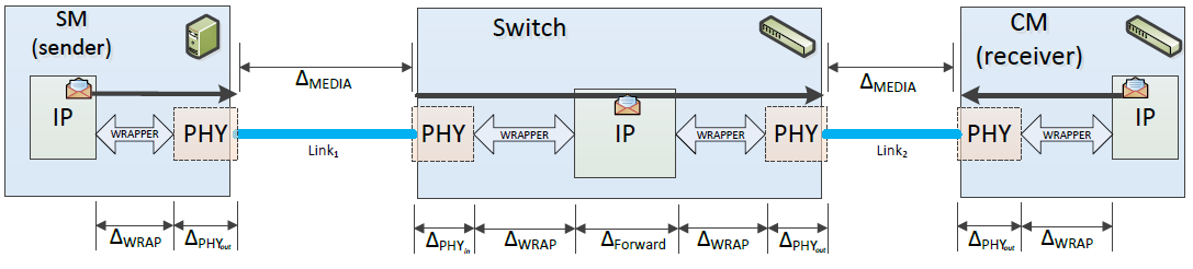 Figure 7-2: Example of delays at system level
After that, going more deep in a typical IP, refinements can be made and additional delay types can be added as illustrated in Figure 7-3:
Controller schedule delays
Controller synchronization delays
Controller interface delays
 Figure 7-3: Example of delays related to a device
Regarding that, as presented in the following Figure 7-4, additional errors can be propagated on the synchronization precision of the network because of the variability of the propagation delays (internal and external).
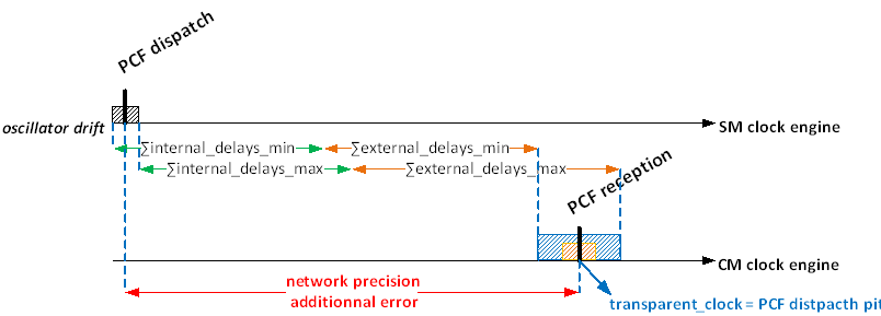 Figure 7-4: Impact of delays on synchronization precision
To increase the synchronization precision of the network and fulfil the precision target, internal and external delays should be compensated (see following Clauses for the precision calculation).
Latencies
The latency of the path for any given PCF, T_DELTA(PCF_i), in a contention-free scenario (i.e. without interference of other network traffic) is computed as the time it takes from a given PCF_i originated at a SM to reach the destination CM, or the other way round, to reach the corresponding SM when originated at the CM.
The worst-case latency, T_DELTA_MAX(PCF_i), accounts for the propagation delay through physical links at their respective media speed, the transmission delay of the PCF frame itself at each hop, in addition to the maximum value for all other delays encountered along the path at each ingress or egress port (e.g. PHY latency, Wrapper, Controller, ...), as well as the forwarding latency of each Switch traversed along the path.
The best-case latency, T_DELTA_MIN(PCF_i), is defined analogously by taking the same delays but with minimum values instead.
Transparent clock
The transparent clock is defined by the sum of the delays on a path from the sender (of a PCF) to the receiver which are taken into account by the transparent clock update function of each device.
T_DELTA_MAX_NC(PCF_i) is defined as T_DELTA_MAX(PCF_i) but taking into account only delays which are not compensated in the pcf_transparent_clock field in PCF (external delays).
The same apply to T_DELTA_MIN_NC(PCF_i) regarding T_DELTA_MIN(PCF_i).
To obtain the maximum transparent clock in a network, it is necessary to calculate the sum of the delays for each path from ES to Switch CM and from Switch CM to ES.
Scheduling requirements
Delays to be identified
ECSS-E-ST-50-16_1490142The static delays, which depend on the physical conditions, shall be identified with minimum and maximum values defined for each use case.
For example, static delays that can be induced by wrappers, transceivers or cables.
ECSS-E-ST-50-16_1490143The dynamic delays, which depend on the load in the network, shall be identified with minimum and maximum values defined for each use case.
For example, dynamic delays due to buffering or computation.
Delays compensation
ECSS-E-ST-50-16_1490144Each node should update the pcf_transparent_clock field of PCF with the accumulated internal delays (as defined in[SAE AS6802] §5.3).
That allows to reduce the uncertainty on the PCF reception as presented in Figure 7-5.
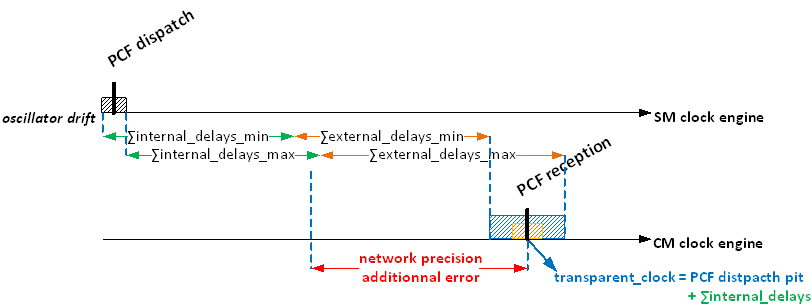 Figure 7-5: Impact of delays on synchronization precision
ECSS-E-ST-50-16_1490145Regarding external delays, each node should allow to configure an external delay value for each physical port in both ways (Rx/Tx).
ECSS-E-ST-50-16_1490146External delay configurable values should be set to the mean value of the related delay range (average between minimum and maximum value).
ECSS-E-ST-50-16_1490147Each node should update the pcf_transparent_clock field of PCF with the appropriate (regarding the physical port used and the way of the transmission) configurable value of external delay (as defined in [SAE AS6802] §5.3).
That allows to reduce again the uncertainty on the PCF reception as presented in Figure 7-6.
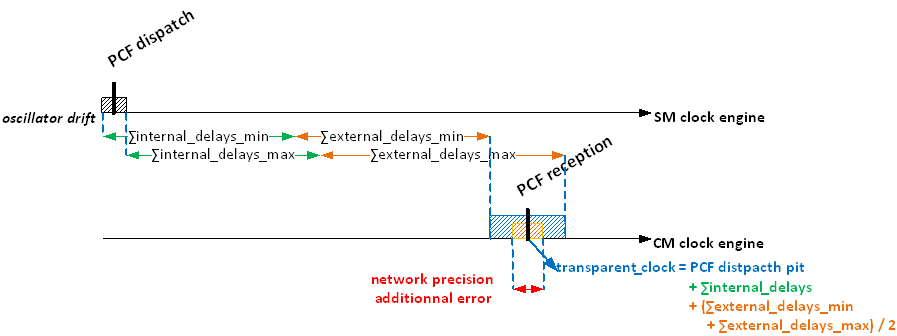 Figure 7-6: Impact of delays on synchronization precision
PCF latency
ECSS-E-ST-50-16_1490148The maximum PCF latency among all PCFs should be defined according to the following formula:
|
MAX_PCF_LATENCY = max( T_DELTA_MAX(PCF_j) : for all j)
|
This value is the minimum bound to be used in the computation of the maximum transparent clock (see below). Any larger value is possible, although the parameter has a relation to the minimum integration cycle duration and indirectly affects the precision quality.
Maximum transparent clock
ECSS-E-ST-50-16_1490149The global maximum transparent clock of the network should be defined according to the following formula:
|
max_transparent_clock = MAX_PCF_LATENCY
|
- 1 Refer to Table 7-16 for parameters description.
- 2 This value is an upper bound for the worst-case latency of any PCF. Any value larger than this bound is possible, although the parameter has a relation to the minimum integration cycle.
Table 7-16: Max Transparent Clock parameter table
|
Parameter
|
Description
|
|
MAX_BE_SHUFFLING = 1538 × 8 / SPEED
|
assuming the largest possible frame-size in case of Shuffling (null if shuffling is not used)
|
|
PCF_SHUFFLING = 84 × 8 / SPEED
|
if the size of the PCF is configured to be a min-size Ethernet frame
|
|
PCF_num_hops
|
is the maximum number of links in the path of a PCF
|
|
T_PCF_reception
|
is the necessary residual time for a PCF on reception (a PCF must be received with at least this margin till the end of the max_transparent_clock to be considered in time) – This time is implementation dependent.
|
PCF transparent clock jitter
ECSS-E-ST-50-16_1490150The maximum jitter bound for PCFs in a contention-free scenario should be the maximum difference between best- and worst-case latency among all PCFs as per the following formula:
|
MAX_PCF_JITTER =max( [T_DELTA_MAX_NC(PCF_j) − F_j) DELTA_MAX_NC(PCF_j) ] : forall j ) |
This value is the minimum bound to be used in the computation of the precision parameter (see below). Any larger value is possible, although the parameter has a relation to the minimum integration cycle duration and directly affects the precision quality.
Precision parameter
ECSS-E-ST-50-16_1490151The precision parameter should include the oscillator drifts impacts and the non-compensated part of the static delays (PCF transparent clock jitter) as per the following formula:
|
Precision = FACTOR × (DRIFT_INT + 2 × MAX_PCF_JITTER)+ 2 × DRIFT_INT × nEsNumUnstableCycles
|
- 1 Refer to Table 7-17 for parameters description.
- 2 This value is the minimum bound to be used. Any larger value is possible, although the parameter has a relation to the acceptance windows size (PCF and TT frames).
Table 7-17: Precision parameter Table
|
Parameter
|
Description
|
|
FACTOR
|
With 1FT hypothesis FACTOR = 8/3
|
|
DRIFT_INT = OSC_PPM × T_INT
|
maximum drift of a local clock during one integration cycle
|
|
MAX_PCF_JITTER
|
This term is multiplied by 2 to take into account the unknowns on the delays (as margins).
|
|
nEsNumUnstableCycles
|
Configurable IP parameter related to how many integration cycles may be tolerated without enough PCFs being received (see [SAE AS6802] standard).
|
Time-Triggered minimum gap
ECSS-E-ST-50-16_1490152The minimum gap between two scheduled virtual links (VL1, VL2) sent by the same End-System should be defined according to the following formula:
|
min_gap = vl2_tx_pit - vl1_tx_pit = vl1_duration + IFG + Preamble + SFD
|
This value is the minimum bound to be used. Any larger value is possible well but the bandwidth usable for TT messages on the related links is decreased. Overlapping Tx windows causes frames to queue on egress if the distance between scheduled send events is less than the min_gap.
Time-Triggered Switch receive window
ECSS-E-ST-50-16_1490153For each TT frames received by a Switch, the receive window, acceptance window, should be defined by a start time and an end time respecting the two formulas provided on Table 7-18.
ECSS-E-ST-50-16_1490154Table 7-18: TT Switch Receive Window start and end time
|
receive_window_start = vl_tx_pit
|
|
receive_window_end = vl_tx_pit
|
- 1 Refer to Table 7-19 for parameters description
- 2 The calculated window with these formulae’s is the smallest possible one. Any larger values are possible but the determinism of the reception will then decrease.
- 3 Overlapping Rx windows are not an issue since an Rx window is necessarily larger than Tx window for the same frame (due to e.g. the clock domain offset between sender and receiver makes the Rx window 2 x precision larger –to cover the two extreme situations in which the sender is 1 precision ahead of time with respect to the receiver as well as 1 precision behind).
Table 7-19: Time-Triggered Switch receive window Table
|
Parameter
|
Description
|
|
MAX_BE_SHUFFLING = 1538 × 8 ÷ SPEED
|
assuming the largest possible frame-size in case of Shuffling (null if shuffling is not used)
|
|
PCF_SHUFFLING = 84 × 8 ÷ SPEED
|
if the size of the PCF is configured to be a min-size Ethernet frame
|
|
NB_MAX_PCF_ON_LINK
|
is the maximum number of PCF transmitted on the link (depends on the topology)
|
|
sw_rx_to_wnd_min
|
is an IP implementation dependent value defining the time until the rx evaluation point within the IP.
|
|
min_frame
|
is the time of a minimum frame size for the VL at the given network speed. A generic value corresponding to the minimum Ethernet frame size can be used:
|
Time-Triggered Switch minimum transmission
ECSS-E-ST-50-16_1490155The minimum gap between a receive_window_end of a virtual link and the vl_tx_pit of the same virtual link should be: sw_min_transmission = 0
The end of the Rx window (as computed above) includes the worst-case scenario (maximum delays, maximum interference, maximum clock offset between sender and receiver) until the frame is in the buffer and ready to be triggered for transmission.
Time-Triggered End-System reception
ECSS-E-ST-50-16_1490156A Switch connected to an End-System configured to receive a TT frame at T_es_receive should send the frame at T_sw_send.
Even if there is no timing filtering in reception on End-System part, it is still important to well define the sending time of the connected Switch to respect receive time constraint
ECSS-E-ST-50-16_1490157The maximum value for T_sw_send should be defined by the formula:
|
T_sw_send <= T_es_receive
|
This value is the maximum bound to be used. Any lower value is possible to respect the receive time constraint. In case of media reservation usage, the parameter MAX_BE_SHUFFLING can be omitted.
Network Setup and Services
Overview
This Clause specifies how the network setup is performed by means of loading the configurations onto the network, how the network is monitored and how error management is handled.
It also describes diagnostics and monitoring mechanisms which are provided by the network components. Such mechanisms aim at collecting raw data, organize them and make them available so that the end user (application or operator) is able to perform the spacecraft FDIR.
To operate a Time-Triggered Ethernet network all components communicating via critical traffic need to be configured in a consistent manner. Moreover, the system needs to be aware of the health status of these components for the overall system FDIR.
The related management services is described within this Clause:
The Dataloading of the application- and the configuration-data via TFTP
The Diagnostic and Status-Information of the network via SNMP
The required Error management functionalities of and End-System and Switch
Since spacecraft networks consist of low complex End-Systems on the network, these services are optional because for e.g. sensor and actuator nodes dataloading via the TFTP protocol is not needed because the configuration could also be hard coded directly into the device. Also, the diagnostics and status information can be transmitted via standard (TT, RC or BE) messages without using the SNMP protocol.
This standard lists the data to be collected but not how to interpret them. Interpretation and analysis of those data are use case and topology specific and can’t be covered in such documentation.
When designing the network architecture, the diagnostics and monitoring mechanism can be tailored to cover the application specificity (see Figure 8-1).
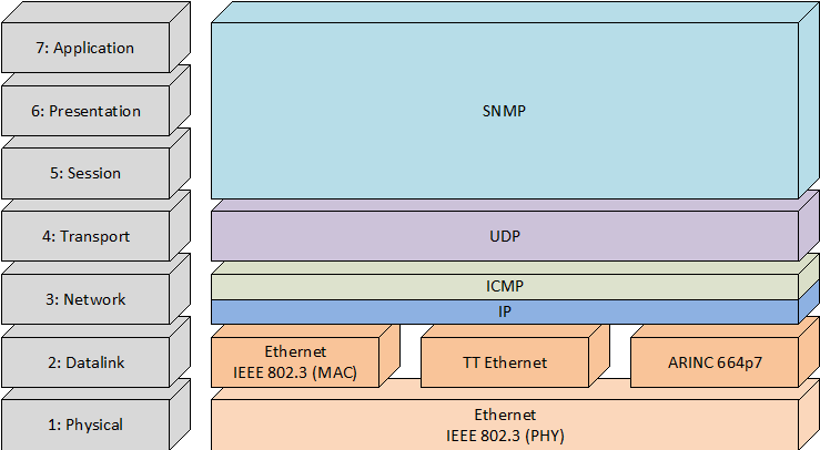 Figure 8-1: Network Diagnostic and Monitoring Service Layers
General Requirements
Overview
This Clause specifies the protocol support that is needed to support upper layer functionalities which are used to ensure the interoperability between the nodes in the network.
Internet Protocol (IP)
ECSS-E-ST-50-16_1490158In transmission, the IPv4 packet structure shall be compliant with [RFC 791] 13 fields defined as follow:
- Version: 4 bits (0100)
- Header Length: 4 bits (0101)
- Type of Service: 1 byte (0x00)
- Total Length: 2 bytes
- Fragment Identification: 2 bytes
- Control Flags: 3 bits
- Fragment Offset: 13 bits
- Time to Live: 1 byte
- Protocol: 1 byte
- Header Checksum: 2 bytes
- Source IP Address: 4 bytes
- Destination IP Address: 4 bytes
- IP Payload: 1-1479 bytes
ECSS-E-ST-50-16_1490159In transmission, in the IPv4 packet structure, the Version field shall be equal to 4 in decimal notation to indicate IP version 4.
ECSS-E-ST-50-16_1490160In reception, in the IP layer, if a check of the Version field is performed and fails, the frame shall be discarded.
It is not required to check of the Version field in reception.
ECSS-E-ST-50-16_1490161In transmission, In the IPv4 packet structure, the Internet Header Length (IHL) field shall be equal to 5 in decimal notation.
ECSS-E-ST-50-16_1490162In reception, in the IP layer, if a check of the Internet Header Length (IHL) is performed and fails, the frame shall be discarded.
It is not required to check the Internet Header Length (IHL) in reception.
ECSS-E-ST-50-16_1490163In transmission, without fragmentation, in the IPv4 packet structure, the IP length shall be equal to the UDP length + 20 bytes.
ECSS-E-ST-50-16_1490164In reception, if the IP datagram is not fragmented, and if the IP length is not equal to the UDP length + 20 bytes, the frame shall be discarded.
ECSS-E-ST-50-16_1490165In transmission, in the IPv4 packet structure, the Time to Live field shall be equal to 1.
To avoid propagation through routers.
ECSS-E-ST-50-16_1490166In reception, in the IP layer, the Time to live field shall not be checked.
This constant field does not need to be checked. All fields in the IP layer are filled in emission according to IPv4. Moreover, in reception, the receiver does not use these fields to take decision: if such fields are corrupted, it is fully transparent for the application.
ECSS-E-ST-50-16_1490167In reception, the frame shall be deleted if the Protocol Type Field of the IP layer is not supported by the End-System.
ECSS-E-ST-50-16_1490168In the IPv4 packet structure, the header checksum field shall be the 16 bit's one's complement of the one's complement sum of all 16 bit words in the header.
ECSS-E-ST-50-16_1490169In reception, if a check of the IP Header Checksum is performed and fails, the frame shall be discarded.
It is not required to check the IP Header Checksum in reception.
UDP
ECSS-E-ST-50-16_1490170In transmission, the UDP packet structure shall be compliant with [RFC 768] with 5 fields defined as follow
- Source Port: 16 bits
- Destination Port: 16 bits
- Length: 16 bits
- Checksum: 16 bits
- UDP Payload: 1-8 Kbytes
ECSS-E-ST-50-16_1490171In transmission, the Length field shall be the length in bytes of the User Datagram including the header and the data.
ECSS-E-ST-50-16_1490172In reception, if the UDP length - 8 bytes is greater than the buffer size, the frame shall be discarded and the MIB counter "UDPInError" be incremented.
ECSS-E-ST-50-16_1490173In transmission, in the UDP structure, the Checksum field shall be set to 0.
The checksum field is not used in UDP.
ECSS-E-ST-50-16_1490174In reception, if a check of the UDP Checksum field is performed and fails, the frame shall be discarded.
It is not required to check the UDP Checksum in reception.
ICMP
ECSS-E-ST-50-16_1490175Switches and End-Systems shall support ICMP using BE traffic class.
Since RC traffic class is optional, the BE traffic class is used for ICMP.
ECSS-E-ST-50-16_1490176A Switch shall be able to reply to an ICMP echo or echo reply request as specified in [RFC 792] version 1.
ECSS-E-ST-50-16_1490177An End-System shall be able to reply to an ICMP echo request as specified in [RFC 792] version 1.
ECSS-E-ST-50-16_1490178In the ICMP structure, the Type field shall be: 8 for an echo message, 0 for an echo reply message.
Most relevant types for space applications.
ECSS-E-ST-50-16_1490179In reception, if the ICMP Type field is not supported, the frame shall be discarded and the MIB counter "ProtocolInError" be incremented.
ECSS-E-ST-50-16_1490180In reception, in the ICMP structure, if a check of the Checksum is performed and fails, the frame shall be discarded.
It is not required to check the ICMP Checksum in reception.
ECSS-E-ST-50-16_1490181In reception, in the ICMP structure, if the data field is not in the range 1 to 64 bytes, the frame shall be discarded.
ECSS-E-ST-50-16_1490182If ICMP is implemented, it shall be available after power on of the network interface.
For factory, test, validation application.
ECSS-E-ST-50-16_1490183If an ICMP frame carries an ICMP service type different from 0, 3, 8 or 11, the frame shall be discarded and the MIB counter ICMProtocolInError be incremented.
They are the 4 allowed ICMP services.
Dataloading via TFTP
Trivial File Transfer Protocol (TFTP) Overview
This service is optional: when implemented, all requirements defined in clause 8.3.2 are applicable.
TFTP is a simple protocol to transfer files. It is implemented on top of the Internet User Datagram protocol (UDP or Datagram). It is designed with low complexity and therefore the implementation can be done with very low effort. It reads and writes files from/to a remote server. In common with other Internet protocols, it passes 8bit bytes of data.
Any transfer begins with a request to read or write a file, which also serves to request a connection. If the server grants the request, the connection is opened, and the file is sent in fixed length blocks of 512 bytes. Each data packet contains one block of data and is acknowledged by an acknowledgment packet before the next packet can be sent. A data packet of less than 512 bytes signals termination of a transfer. If a packet gets lost in the network, the intended recipient timeouts and can retransmit his last packet (which can be data or an acknowledgment), thus causing the sender of the lost packet to retransmit that lost packet. The sender has to keep just one packet on hand for retransmission, since the lock step acknowledgment guarantees that all older packets have been received. Notice that both machines involved in a transfer are considered senders and receivers. One sends data and receives acknowledgments; the other sends acknowledgments and receives data.
The TFTP protocol has basically 5 types of messages as given in Figure 8-2 below:
The RRQ and WRQ messages are used by the client to request the server to start reading or writing a file respectively. Both these messages send the file name and transfer mode (ASCII or binary) as additional parameters.
The DATA messages carry the actual file blocks, with each message carrying a block of data. Each block has a sequence number field indicating the block number.
The ACK message is used to acknowledge successfully received data blocks. It has the sequence number as the additional parameter, indicating the block number that was successfully received. Whenever a block is received error free (indicated by the UDP checksum), then the receiving TFTP node immediately acknowledges the block to the peer, by sending an ACK message.
The ERROR message is sent to the peer whenever some operation could not be performed (e.g. invalid file name, file does not have read/write permissions etc.).
TFTP protocol has been enhanced to allow for additional option negotiations like initial sequence number, block size etc.
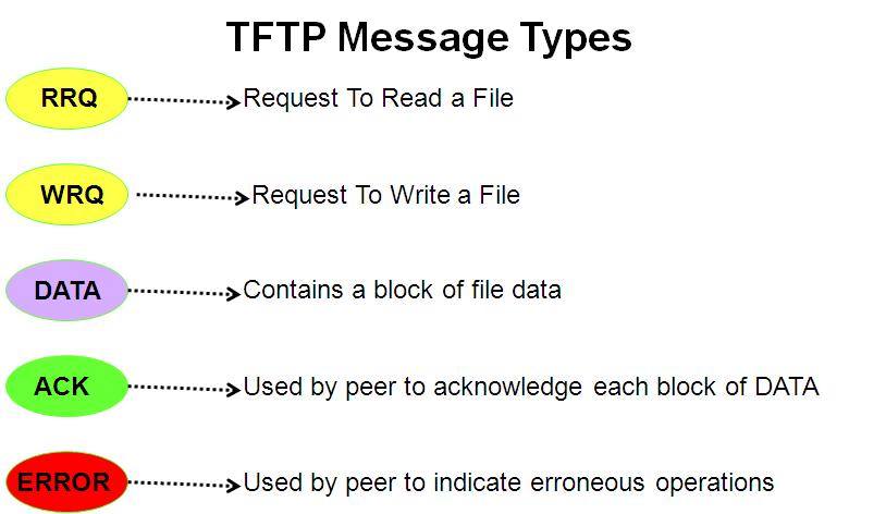 Figure 8-2: FTP Message Types
Dataloading requirements
ECSS-E-ST-50-16_1490184The Switches should use the TFTP client according to [RFC 1350] and [RFC 768] functionality for downloading and uploading of configuration and firmware.
ECSS-E-ST-50-16_1490185The End-Systems should use the TFTP client according to [RFC 1350] and [RFC 768] functionality for downloading and uploading of configuration and firmware.
ECSS-E-ST-50-16_1490186A TFTP server according to [RFC 1350] and [RFC 768] should be used to provide the configuration and application data to the network.
ECSS-E-ST-50-16_1490187In the UDP port, if a buffer overflow occurs in reception, an ERROR packet (opcode 5) should be sent to the client and the frame be discarded.
ECSS-E-ST-50-16_1490188Each TFTP client and server should support the following configurable parameters:
- Default Timeout: sets the packet timeout.
- Retry Count: sets the retry limit.
The use of [RFC 2349] (TFTP Timeout Interval and Transfer Size Options) to define the Timeout as a negotiated parameter under the framework defined by [RFC 1782] (TFTP Option Extension) is not considered in this standard.
Diagnostics and Status-Information via SNMP
Simple Network Management Protocol (SNMP) Overview
This service is optional: when implemented, all requirements defined in clauses 8.4.2, 8.4.3 and 8.4.4 are applicable.
Simple Network Management Protocol (SNMP) is mainly used in network management systems to monitor network-attached devices for conditions that warrant administrative attention. It is the most popular network management protocol in the TCP/IP protocol suite.
SNMP is a request/response protocol that communicates management information between two types of SNMP software entities: SNMP managers and SNMP agents. The following picture in Figure 8-3 shows an exemplary setup:
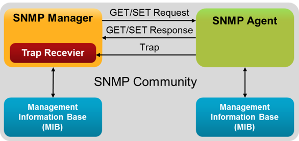 Figure 8-3: Simple Network Management Protocol (SNMP)
For space application it has been decided to use the SNMPv1 which has been judged as sufficient to cover the technical needs. There is no backward compatibility between SNMPv2 and after with SNMPv1.
In summary, SNMP performs the following operations:
The GET operation receives a specific value about a managed object, such as the available hard disk space from the agent's MIB.
The GET-NEXT operation returns the "next" value by traversing the MIB tree of managed object variables.
The SET operation changes the value of a managed object's variable. Only variables whose object definition allows read/write access can be changed.
The Trap operation sends a message to the Management Station when a change occurs in a managed object, and that change is important enough to send an alert message.
The SNMP Agent validates each request from a SNMP manager before responding to the request, by verifying that the manager belongs to a SNMP community with access privileges to the agent. A SNMP community is a logical relationship between a SNMP agent and one or more SNMP managers. The community has a name, and all members of a community have the same access privileges: either read-only or read-write.
The data base controlled by the SNMP Agent is referred to as the SNMP Management Information Base (MIB). It is a standard set of statistical and control values. SNMP allows the extension of these standard values with values specific to a particular agent through the use of private MIBs.
The goals of the SNMP protocol are:
Monitor the global status of equipment (active, inactive, partially operational);
Manage exceptional events such as the loss of a link network or an abrupt shutdown of an equipment;
Analyse different metrics to anticipate future problems such as network congestion;
Act on some elements of the configuration of the equipment.
The different elements that can be identified with the SNMP protocol are summarized by the diagram at Figure 8-4 in which:
The SNMP agent is the application embedded in the equipment to supervise.
The SNMP supervisor is a central machine from which an operator can supervise its entire infrastructure in real-time, diagnose problems to help troubleshooting.
The SNMP protocol is the protocol used by SNMP agents and their supervisors to communicate with each other.
The MIB is the information Dynamics instantiated by the various SNMP agents and lifts in real-time to the supervisor.
The SNMP tools are the different utilities used by the supervisor to help diagnose a problem. These tools are also used when you set up the supervisor to take into account the specificities of the infrastructure.
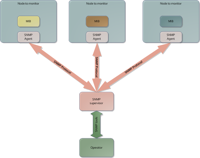 Figure 8-4: Global SNMP architecture
SNMP requirements
ECSS-E-ST-50-16_1490189The Switch should use the SNMP Agent functionality according to [RFC 1157] to provide its diagnostics and status information from the Switch.
ECSS-E-ST-50-16_1490190A host connected to an End-System should implement the SNMP Agent functionality according to [RFC 1157] to provide its diagnostics and status information from the Switch.
ECSS-E-ST-50-16_1490191An SNMP Manager according to [RFC 1157] should be used on a host connected to the network to perform the network management tasks needed.
Diagnostic and Status-Information requirements
End-System Management Information Database (MIB) requirements
ECSS-E-ST-50-16_1490192In reception, if a frame of the End-System does not have a correct length, the MIB counter MACRxFramesErrors should be incremented.
Ethernet II MAC Length:
- For MAC length=64 bytes, if the IP length (in bytes) + K1 bytes is greater than 64 bytes.
- For MAC length>64 bytes, if the MAC length (in bytes) is not equal to IP length (in bytes) + K1 bytes.
K1 is equal to 18 bytes if SN is not used and equal to 19 if SN is used, MAC length does not include the FCS length (4 bytes).
[IEEE 802.3] MAC Length:
- For MAC length=64 bytes, if the Ethernet length (in bytes) + 18 bytes is greater than 64 bytes.
- For MAC length>64 bytes, if the MAC length (in bytes) is not equal to Ethernet length (in bytes) + 18 bytes.
MAC length does not include the FCS length (4 bytes).
ECSS-E-ST-50-16_1490193In reception, if the End-System is designed to handle new frame although the interframe gap has been smaller than 11 bytes, the MIB counter tteIFGErr should be incremented.
ECSS-E-ST-50-16_1490194In reception, if a frame is discarded due to invalid size, the MIB counter tteEsEthPortNoLossLengthError should be incremented.
ECSS-E-ST-50-16_1490195In reception, if a frame has to be discarded because the receiving buffer was full, the MIB counter tteDropNoMem counter should be incremented.
ECSS-E-ST-50-16_1490196In an End-System, when a MIB is implemented, it should at least contain the following fields at the root:
- tteSyncState - containing the TTE clock synchronization state
- tteSyncLoss - counter of the number of transitions to from SYNC or STABLE state to any other state
ECSS-E-ST-50-16_1490197In an End-System, when a MIB is implemented, it should have an entry called “configuration”.
ECSS-E-ST-50-16_1490198In an End-System, when a MIB is implemented, the entry called “configuration” should at least contains the following fields: - tteDevId - containing the End-System device ID
- tteDevRev - containing the End-System device revision
- tteDevItfRev - containing the End-System interface revision
To allow identifying an End-System.
ECSS-E-ST-50-16_1490199In an End-System tteEsCfgSignature should containing the signature of the configuration file.
ECSS-E-ST-50-16_1490200If a check of the ICMP Header Checksum of the End-System is performed and fails, the frame should be discarded and the MIB counter ICMProtocolInError be incremented.
ECSS-E-ST-50-16_1490201If the structure of an ICMP frame is checked and fails, the frame should be discarded and the MIB counter ICMProtocolInError be incremented.
ECSS-E-ST-50-16_1490202If an ICMP frame length of the End-System is smaller than 1 bytes, the frame should be discarded and the MIB counter ICMProtocolInError be incremented.
ECSS-E-ST-50-16_1490203If an ICMP frame length of the End-System is greater than 64 bytes, the frame should be discarded and the MIB counter ICMProtocolInError be incremented.
Switch Management Information Database (MIB) requirements
ECSS-E-ST-50-16_1490204In reception, if a frame of the Switch does not have a correct length, the MIB counter MACRxFramesErrors should be incremented.
ECSS-E-ST-50-16_1490205In a Switch, the MIB should contain the following fields at the root:
- tteSweSyncState - containing the TTE clock synchronization state
- tteSweNumberOfSyncLoss - counter of the number of transitions to from SYNC or STABLE state to any other state
ECSS-E-ST-50-16_1490206In a Switch, the MIB should have an entry called “configuration”.
ECSS-E-ST-50-16_1490207In a Switch, the entry called “configuration” should at least contains the following fields: - tteSweDevId - containing the Switch device ID
- tteSweDevRev - containing the Switch device revision
- tteSweDevItfRev - containing the Switch interface revision
- tteSweCfgSignature - containing the signature of the configuration file
- 1 To allow identifying a Switch and its content.
- 2 In a Switch, the MIB should have an entry called “Ports”.
ECSS-E-ST-50-16_1490208In a Switch, the entry called “Ports” should at least contains following fields - numberOfPorts - containing the number of functional ports in the Switch
- lowestPort - containing the number of the port having the lowest number
It is possible that a Switch doesn’t use all its ports. Port numbering can start from 0 or any value depending on the implementation.
ECSS-E-ST-50-16_1490209In a Switch, the entry called “Ports” should contain 1 sub-entry for each port in use.
ECSS-E-ST-50-16_1490210In a Switch sub-entries should be named “PortN”, where N is the number of the port.
ECSS-E-ST-50-16_1490211In a Switch, each sub-entry called “PortN” should at least contain the following fields:
- tteSweEthPortName - containing the name of the port
- tteSweEthPortTxBytes - containing the amount of bytes sent through this port
- tteSweEthPortTxFrames - containing the amount of frames sent through this port
- tteSweEthPortRxBytes - containing the amount of bytes received through this port
- tteSweEthPortRxFrames - containing the amount of frames received through this port
- tteSweEthPortNoLossBePolicing
- tteSweEthPortNoLossCtPolicing
- tteSweEthPortNoLossUnknownVl
- tteSweEthPortNoLossCrcError
- tteSweEthPortNoLossLengthError
- tteSweEthPortNoLossSofError
- tteSweEthPortNoLossAlignmentError
See Clause 8.4.3 for details.
ECSS-E-ST-50-16_1490212In a Switch, the MIB should have an entry called “Statistics”.
ECSS-E-ST-50-16_1490213In a Switch, the entry called “Statistics” should at least contains following fields
- numberOfErrReport - containing the number of error reports
ECSS-E-ST-50-16_1490214In a Switch, the entry called “Statistics” should contain 1 sub-entry for each for each error report.
ECSS-E-ST-50-16_1490215In a Switch sub-entries should be named “ErrorN”, where N is the number of the error report.
ECSS-E-ST-50-16_1490216In a Switch, the sub-entry called “ErrorN” should contain at least the following fields to describe the error it is reporting: - ErrorType - containing the type of error
- ErrorField - containing the value of the field identified as faulty
- ErrorOrigin - containing the MAC address of the originator of the faulty frame
- ErrorTimeStamp - containing the date of the failure
ECSS-E-ST-50-16_1490217If a check of the ICMP Header Checksum of the Switch is performed and fails, the frame should be discarded and the MIB counter ICMProtocolInError be incremented.
ECSS-E-ST-50-16_1490218If a check of the structure of an ICMP frame is performed and fails, the frame should be discarded and the MIB counter ICMProtocolInError be incremented.
ECSS-E-ST-50-16_1490219If an ICMP frame length of the Switch is smaller than 1 bytes, the frame should be discarded and the MIB counter ICMProtocolInError be incremented.
ECSS-E-ST-50-16_1490220If an ICMP frame length of the Switch is greater than 64 bytes, the frame should be discarded and the MIB counter ICMProtocolInError be incremented.
ECSS-E-ST-50-16_1490221In reception, if the Switch receives a frame with an incorrect CRC, the frame should be discarded and the tteSweEthPortNoLossCrcError counter of the relevant port entry be incremented.
ECSS-E-ST-50-16_1490222In reception, if the Switch receives a frame with an incorrect CRC, the tteSweEthPortNoLossCrcError counter of the relevant port entry should be incremented.
ECSS-E-ST-50-16_1490223In reception, if the Switch receives a frame with a VL number not consistent with the port number it is received through, the tteSweEthPortNoLossUnknownVl counter of the relevant port entry should be incremented.
ECSS-E-ST-50-16_1490224In reception, if a TT frame is received outside its scheduled time window, the tteSweEthPortNoLossCtPolicing counter of the relevant port entry should be incremented.
ECSS-E-ST-50-16_1490225In reception, if a frame is received has an inconsistent length, the tteSweEthPortNoLossLengthError counter of the relevant port entry should be incremented.
ECSS-E-ST-50-16_1490226In reception, if a frame has an invalid preamble or Start Frame Delimiter, tteSweEthPortNoLossSofError counter of the relevant port entry should be incremented.
ECSS-E-ST-50-16_1490227In reception, if a frame has a length which is not a multiple of 8 bits, the frame should be discarded and a tteSweEthPortNoLossAlignmentError counter of the relevant port entry be incremented.
ECSS-E-ST-50-16_1490228In reception, if a BE frame is received and the MAC source address does not match the configured MAC source address, the frame should be discarded and the tteSweEthPortNoLossBePolicing counter of the relevant port entry be incremented.
Monitoring Mode
ECSS-E-ST-50-16_1490229Each Switch of a TTEthernet network should provide a port for Spy mode.
It can be a port temporarily allocated (configurable) or a physically isolated port.
ECSS-E-ST-50-16_1490230If a Switch of a TTEthernet network provides a physically isolated Spy mode port, it should use a dedicated communication interface.
Error management in End-System and Switch
ECSS-E-ST-50-16_1490231An error shall be characterized by at least:
- The type of error
- The node or the component which is affected by the error ECSS-E-ST-50-16_1490232An error report shall contain at least:
- The type of failure
- The node or the component which is affected by the failure
- A time reference to locate the failure in the timeline
- The cause of the failure
The time reference can be absolute (date) or relative (number of integration cycle).
ECSS-E-ST-50-16_1490233An error report shall be emitted if the diagnostics process failed.
This can occur when one of the elements to be reported can’t be retrieved (type, node, time or cause).
ECSS-E-ST-50-16_1490234When defining a failure state, the reset condition of this state shall be defined. The allowed condition types are:
- Event-driven
- Time-driven
- Persistent (i.e. cannot be reset) ECSS-E-ST-50-16_1490235A failure reset condition shall be an adjustable parameter.
The resiliency of a subsystem to error is implementation dependent.
ECSS-E-ST-50-16_1490236A monitoring process shall be characterized by:
- The elements to be observed
- The frequency of observation ECSS-E-ST-50-16_1490237A monitoring process shall be characterized by a parameter.
They can be adjusted according to the need of the implementation or the operational phase.
ECSS-E-ST-50-16_1490238In a TTEthernet network each of the parameters shall be retrievable individually.
Test and verification
Test Specification
ECSS-E-ST-50-16_1490239All the elements that belong to the same network, for a given system, shall be tested against the same system’s test specification.
Using a common test specification ensures the compatibility of the different elements of the network, even those that have not been specifically developed for the corresponding mission.
ECSS-E-ST-50-16_1490240The test specification shall contain specific chapters for the different elements of the network.
Examples of different elements of network are End-System, Switch.
ECSS-E-ST-50-16_1490241The test specification shall cover at least the most demanding condition that the system requires to each of its elements.
ECSS-E-ST-50-16_1490242In case an element of the network has its own test specification, a compliance matrix against the system test specification shall be prepared.
Test references
Overview
Time-Triggered networks can have very different architectures and degrees of complexity. This is the reason why this standard does not provide detailed verification requirements, since they are tightly dependent on the implementation.
There are many commercial products available aimed at testing Ethernet’s physical layers, on all of its standard variants.
Requirements for implementation at system level
ECSS-E-ST-50-16_1490243The physical layer of each element of the TTEthernet network shall be tested to verify their compliance with the corresponding Ethernet standard (10 Mbit/s, 100 Mbit/s, 1 Gbit/s…) applicable for this network.
ECSS-E-ST-50-16_1490244For Network synchronization, it shall be checked that all the elements that form the TTEthernet network are correctly synchronized after applying the same procedure that is conducted to set the network in Flight configuration.
ECSS-E-ST-50-16_1490245The network shall be configured and monitored using the same procedures that is applied to set the network in Flight configuration.
This includes the use of the foreseen services (TFTP, SNMP…).
ECSS-E-ST-50-16_1490246The worst cases in terms of Best-Effort and Rate-Constrained traffics shall be tested to check the consistency of the configuration of the network.
ECSS-E-ST-50-16_1490247It shall be checked that the network’s redundancy management works as foreseen in the System’s specification.
Tailoring
Scope
Tailoring is a process by which individual requirements or specifications, standards and related documents are evaluated and made applicable to a specific project, by selection of requirements.
This Clause provides recommendations, guidelines and templates for tailoring according to project requirements. Tailoring information and general policy is described in ECSS-S-ST-00.
Tailoring options and parameters
Overview
Most of the services requirements defined in this standard are not configurable. However, there are options identified as well as different levels of performance depending on the value assigned to services managed parameters. It is necessary to specify those parameters for a given project in accordance with user’s communication requirements.
It is recommended to perform tailoring in the two steps described in 10.2.2 and 10.2.3.
Step 1: Function and service selection
First level of tailoring is the selection of the functions and services that are applicable to the project; the Table 10-1 provides a requirement applicability matrix template.
Step 2: Services configuration
Second level of tailoring is the configuration of the services management parameters which are defined within the user service requirements normative Clauses as stated in Table 10-1. This configuration adapts the services characteristics and performance according to the project requirements. Table 10-2 and Table 10-3 provide a template for the configuration of the managed parameters for the functions and services listed in the Table 10-1.
Table 10-1: Requirements selection
|
Function/service
|
Clauses
|
Applicability
|
|
Physical layer
|
4.2
|
Not part of this standard.
|
|
Data link layer
|
4.3
|
Always applicable.
|
|
Service definition
|
6
|
Optional.If selected for a mission the requirements are normative for the Switch.
|
|
Clock Synchronization
|
7.2.5
|
Always applicable.
|
|
Redundancy and Fault Tolerance
|
5, 6
|
Optional.If selected for a mission the requirements are normative for the End-System and the Switch.
|
IEEE 802.3 Tailoring
The tailoring to [IEEE 802.3] - Part 3: Carrier sense multiple access with collision detection (CSMA/CD) access method and physical layer specifications is provided within this Clause and defined in Table 10-2.
Table 10-2: Tailoring to [IEEE 802.3] - Part 3
|
Standard Tag
|
Requirement
|
Applicability
|
|
3.2
|
The Ethernet frame shall be composed of the following fields:
|
Always applicable
|
|
3.2.1
|
Preamble Field
|
Always applicable
|
|
3.2.2
|
Start Frame Delimiter (SFD) field
|
Always applicable
|
|
3.2.3
|
Address fields
|
Always applicable
|
|
3.2.4
|
The MAC frame format shall maintain a destination address field.
|
Always applicable
|
|
3.2.5
|
The MAC frame format shall maintain a source address field.
|
Always applicable
|
|
3.2.6
|
The MAC frame format shall maintain a length/type field.
|
Always applicable
|
|
3.2.7
|
The MAC frame format shall maintain a data field.
|
Always applicable
|
|
3.2.8
|
For Frame Check Sequence Field a CRC value shall be calculated based on Destination Address, Source Address, Length/Type and Data fields.
|
Always applicable
|
|
3.4
|
A frame that meets at least one of the following conditions shall be considered as invalid MAC frame and discarded:
|
Always applicable
|
|
4.2.3.1
|
The MAC sublayer shall provide capability for encapsulation of transmits data.
|
Always applicable
|
|
4.2.3.2.1
|
Full duplex mode
|
Always applicable
|
|
4.2.3.2.2
|
MAC sublayer shall start the transmission of a frame at least interFrameGap time after the previous frame has been transmitted.
|
Always applicable
|
|
4.2.4.1
|
The MAC sublayer shall provide capability for decapsulation of received data.
|
Always applicable
|
|
4.2.4.1.2
|
The frame shall be identified as invalid if the frames bits, excluding the FCS field, do not generate a CRC value identical to the one received in the FCS field.
|
Always applicable
|
|
4.2.4.2
|
Upon reception of a receiveData-Valid signal provided by the Physical Layer in MII/GMII interfaces, MAC sublayer indicates a length error if one of the following:
|
Always applicable
|
|
4.2.4.2
|
When operating in Full Duplex mode the MAC sublayer shall discard any frame having the length less than minFrameSize.
|
Always applicable
|
|
4.4.2.4
|
A frame that meets at least one of the following conditions shall be considered as invalid MAC frame and discarded:
|
Always applicable
|
|
4.2.5
|
The value of preamble shall be a 7-byte field of alternating "10" patterns.
|
Always applicable
|
|
4.2.6
|
The Start-of-frame delimiter (SFD) field shall:
|
Always applicable
|
|
35.2.2
|
The GMII interface shall consist of the following signals:
|
Always applicable
|
|
40
|
The transceiver shall implement the Physical Coding Sublayer (PCS), Physical Medium Attachment (PMA) sublayer and baseband medium, type 1000 BASE-T.
|
Optional.
|
|
Annex 31B.1
|
A MAC control pause frame, used for inhibiting transmission of the BE data frames from another station on the network shall have the following fields set to the specified values:
|
Always applicable
|
|
Annex 31B.1
|
The PAUSE frames shall be generated regardless the received PAUSE operations.Guideline: The PAUSE operation cannot be used to inhibit transmission of MAC Control frames, TT frames and RC frames.
|
Always applicable
|
|
Annex 31B.1
|
The bridge shall discard the frames sent to the PAUSE multicast destination address, regardless of the state of the bridge's ports.
|
Always applicable
|
SAE AS6802 Tailoring
All requirements of the [SAE AS6802] standard are applicable except the following one (see Table 10-3).
Table 10-3: Tailoring to [SAE AS6802]
|
Standard Tag
|
Requirement
|
Applicability
|
|
4.6
|
The Time-Triggered Ethernet device, when acting as a synchronization master or synchronization client, shall be configurable to also accept PCFs with a priority other than their own.
|
Optional.
|
ANNEX(informative)Patent licensing
Scope
The Time-Triggered Ethernet technology specified within this standard is based on patents from the following parties:
Airbus for AFDX
TTTech for patents listed in A.2
With respect to the patents owned by TTTech and the ones owned jointly with Honeywell, the patent licensing described below in section A.2 applies.
A license agreement on usage of these patents for implementing a product compliant to this ECSS standard in a space project can be obtained from ESA. The TTE Patent licence request forms to be filled are provided in Annex A.3.
Time-Triggered Ethernet Patent Overview
Table: Clock Synchronization
|
Short
|
Patent #
|
Description
|
|
F30
|
WO 2009/146472
|
Method for synchronizing local clocks in a distributed computer network*
|
|
F31
|
EP 2 148 474
|
Multirouter for time-controlled communication systems*
|
|
F9
|
WO 2001/84286
|
Multi-master Clock-Synchronization*
|
|
T32/F31
|
WO 2009/146471
|
Method for Synchronizing Local Clocks**
|
|
F37
|
WO 2011/123877
|
Method and Device for Fault-tolerant Time-Triggered Real-Time Communication*
|
|
NOTES:
| ||
Table: Time-Triggered Communication
|
Short
|
Patent #
|
Description
|
|
F12
|
WO 2002/075557
|
Realization of Event-Channels in a TT Communication System*
|
|
F14
|
WO 2003/107609
|
Time-Triggered Ethernet*
|
|
F16
|
WO 2004/107670
|
Transmission of Messages in a TT System*
|
|
F23
|
WO 2008/124854
|
Communication Method and Device for Efficient and Secure Transmission of TT Ethernet Messages*
|
|
F28
|
WO2009/121087
|
Method for Secure Dynamic Bandwidth Allocation in TT Ethernet*
|
|
F53
|
WO2013/170285
|
Method and Device for Relaying TT and ET Messages*
|
|
NOTES:
| ||
Table: Dependability
|
Short
|
Patent #
|
Description
|
|
F41
|
WO 2009/146472
|
Method for synchronizing local clocks in a distributed computer network*
|
|
F15
|
WO 2004/023302
|
Error Detection Method*
|
|
S06
|
EP 1 222 542
|
Method for Enforcing the Fail-Silent Property in a Distributed Computer System and Distributor Unit of Such a System*
|
|
T10
|
WO 2007/000007
|
Safe start-up of a network**
|
|
F23
|
EP 2 145 431
|
Procedure and Architecture for the protection of real time data*
|
|
F56
|
WO 2014/134652
|
Method for Increasing the Reliability in a TT System*
|
|
NOTES:
| ||
TTE Patent licence request form
|
Licensee
| |
|
Entity Complete Name and Legal Nature (1)
|
|
|
Entity Address of its Seat
|
|
|
Post code
|
|
|
City
|
|
|
Country (ISO Code)
|
|
|
Contact person to whom all communication related to the request should be addressed
| |
|
Name:
|
|
|
Telephone no.:
|
|
|
Fax no.:
|
|
|
Email address:
|
|
|
Licensor
| |
|
Entity Complete Name and Legal Nature (1)
|
TTTech Computertechnik AG (TTTech)
|
|
Entity Address of its Seat
|
Schoenbrunner Strasse 7
|
|
Post code
|
1040
|
|
City
|
Vienna
|
|
Country (ISO Alpha 3 Code)
|
Austria (AUT)
|
|
Contact person to whom all communication related to the request should be addressed
| |
|
Name:
|
|
|
Telephone no.:
|
|
|
Fax no.:
|
|
|
Email address:
|
XXXXX@tttech.com
|
|
(1) Specify here the type of business entity to which the company belongs (e.g. Limited Company, Société Anonyme, AG etc.).
| |
|
Licensed TTE Patents
| ||
|
Short
|
Patent #
|
Description
|
|
F30
|
WO 2009/146472
|
Method for synchronizing local clocks in a distributed computer network
|
|
F31
|
EP 2 148 474
|
Multirouter for time-controlled communication systems
|
|
F9
|
WO 2001/84286
|
Multi-master Clock-Synchronization
|
|
…. |
… |
…. |
Licensed Patents information
The Licensee hereby requests from the Licensor the authorisation to use the Licensed TTE Patents according to the terms and conditions of the Agreement between ESA, acting on behalf of the members of the European Cooperation for Space Standardization (ECSS), and TTTech on the use of the TTE Patents and TTE Products, reference …, dated … (hereinafter referred to as Agreement).
The Licensee confirms that the licence and the Licensed TTE Patents shall be used solely for space applications based on the ECSS TTE Standard (ECSS-E-ST-50-16C) in line with the terms and conditions of the Agreement.
(if applicable)
The licence and the Licensed TTE Patents shall be used for a limited period, starting from […] and ending on […].
Date: ..............................
Signature: ..............................
Name and title of the signatory: ........................ (Full name and function) duly authorized to commit the requesting entity for this purpose.
Bibliography
|
ECSS-S-ST-00
|
ECSS system – Description, implementation and general requirements
|
|
ECSS-E-ST-70-41
|
Space engineering - Telemetry and Telecommand packet utilization
|
|
ARINC 664
|
Available from ARINC, 2551 Riva Road, Annapolis, MD 21401. www.arinc.com
|
|
ARINC 664 part 2, 24 October 2018
|
Aircraft Data Network Part 2: Ethernet Physical and Data Link Layer Specification
|
|
ARINC 653
|
Available from ARINC, 2551 Riva Road, Annapolis, MD 21401. www.arinc.com
|
|
IEEE 802.3
|
Ethernet Standard, available from the Institute of Electrical and Electronics Engineers (IEEE), 445 Hoes Lane, Piscataway, NJ 08854-1331, Tel: 732-981-0060, www.ieee.org
|
|
RFC 826
|
Ethernet Address Resolution Protocol
|
|
[SAE AS6802]
|
Time-Triggered Ethernet, Available from the Society of Automotive Engineers (SAE) International, SAE International Headquarters, 400 Commonwealth Dr., Warrendale, Pennsylvania, USA, standards.sae.org
|
|
ESCC
|
ESCC publications: https://escies.org ESCC 3902/003 and ESCC 3401/071 are also posted at http://www.estec.esa.nl/tech/spacewire/literature
|
|
CCSDS 702.1-B-1
|
IP over CCSDS space links, CCSDS Secretariat Space Communications and Navigation Office, 7L70, Space Operations Mission Directorate, NASA Headquarters Washington, DC 20546-0001, USA
|
|
CCSDS 850.0-G-2
|
Spacecraft Onboard Interface Services Informational Report, December 2013
|
|
RFC 768
|
User Datagram Protocol
|
|
RFC 791
|
Internet Protocol
|
|
RFC 792
|
Internet Control Message Protocol (ICMP)
|
|
RFC 1157
|
A simple network management protocol (for SNMPv1)
|
|
RFC 1350
|
The TFTP Protocol (Revision 2)
|
|
RFC 1441
|
Introduction to version 2 of the Internet-standard Network Management Framework (for SNMP V2)
|
|
RFC 3411
|
An Architecture for Describing Simple Network Management Protocol Management Frameworks (for SNMP V3)
|
|
RFC 2349
|
TFTP Timeout Interval and Transfer Size Options
|
|
RFC 3697
|
IPv6 Flow Label Specification
|