
Space engineering
Structural factors of safety for spaceflight hardware
Foreword
This Standard is one of the series of ECSS Standards intended to be applied together for the management, engineering and product assurance in space projects and applications. ECSS is a cooperative effort of the European Space Agency, national space agencies and European industry associations for the purpose of developing and maintaining common standards. Requirements in this Standard are defined in terms of what shall be accomplished, rather than in terms of how to organize and perform the necessary work. This allows existing organizational structures and methods to be applied where they are effective, and for the structures and methods to evolve as necessary without rewriting the standards.
This Standard has been prepared by the ECSS-E-ST-32-10C Working Group, reviewed by the ECSS Executive Secretariat and approved by the ECSS Technical Authority.
Disclaimer
ECSS does not provide any warranty whatsoever, whether expressed, implied, or statutory, including, but not limited to, any warranty of merchantability or fitness for a particular purpose or any warranty that the contents of the item are error-free. In no respect shall ECSS incur any liability for any damages, including, but not limited to, direct, indirect, special, or consequential damages arising out of, resulting from, or in any way connected to the use of this Standard, whether or not based upon warranty, business agreement, tort, or otherwise; whether or not injury was sustained by persons or property or otherwise; and whether or not loss was sustained from, or arose out of, the results of, the item, or any services that may be provided by ECSS.
Published by: ESA Requirements and Standards Division
ESTEC, P.O. Box 299,
2200 AG Noordwijk
The
Copyright: 2009 © by the European Space Agency for the members of ECSS
Change log
|
ECSS-E-ST-32-10A
|
Never issued
|
|
ECSS-E-ST-32-10B
|
Never issued
|
|
ECSS-E-ST-32-10C
|
First issue
|
|
ECSS-E-ST-32-10C Rev.1
|
First issue revision 1
|
Scope
The purpose of this Standard is to define the Factors Of Safety (FOS), Design Factor and additional factors to be used for the dimensioning and design verification of spaceflight hardware including qualification and acceptance tests.
This standard is not self standing and is used in conjunction with the ECSS-E-ST-32, ECSS-E-ST-32-02 and ECSS-E-ST-33-01 documents.
Following assumptions are made in the document:
that recognized methodologies are used for the determination of the limit loads, including their scatter, that are applied to the hardware and for the stress analyses;
that the structural and mechanical system design is amenable to engineering analyses by current state-of-the-art methods and is conforming to standard aerospace industry practices.
Factors of safety are defined to cover chosen load level probability, assumed uncertainty in mechanical properties and manufacturing but not a lack of engineering effort.
The choice of a factor of safety for a program is directly linked to the rationale retained for designing, dimensioning and testing within the program. Therefore, as the development logic and the associated reliability objectives are different for:
unmanned scientific or commercial satellite,
expendable launch vehicles,
man-rated spacecraft, and
any other unmanned space vehicle (e.g. transfer vehicle, planetary probe)
specific values are presented for each of them.
Factors of safety for re-usable launch vehicles and man-rated commercial spacecraft are not addressed in this document.
For all of these space products, factors of safety are defined hereafter in the document whatever the adopted qualification logic: proto-flight or prototype model.
For pressurized hardware, factors of safety for all loads except internal pressure loads are defined in this standard. Concerning the internal pressure, the factors of safety for pressurised hardware can be found in ECSS-E-ST-32-02. For loads combination refer to ECSS-E-ST-32-02.
For mechanisms, specific factors of safety associated with yield and ultimate of metallic materials, cable rupture factors of safety, stops/shaft shoulders/recess yield factors of safety and limits for peak Hertzian contact stress are specified in ECSS-E-ST-33-01.
Alternate approach
The factors of safety specified hereafter are applied using a deterministic approach i.e. as generally applied in the Space Industry to achieve the structures standard reliability objectives. Structural safety based on a probabilistic analysis could be an alternate approach but it has to be demonstrated this process achieves the reliability objective specified to the structure. The procedure is approved by the customer.
This standard may be tailored for the specific characteristics and constraints of a space project in conformance with ECSS-S-ST-00.
Normative references
The following normative documents contain provisions which, through reference in this text, constitute provisions of this ECSS Standard. For dated references, subsequent amendments to, or revision of any of these publications, do not apply. However, parties to agreements based on this ECSS Standard are encouraged to investigate the possibility of applying the more recent editions of the normative documents indicated below. For undated references, the latest edition of the publication referred to applies.
|
ECSS-S-ST-00-01
|
ECSS system – Glossary of terms
|
|
ECSS-E-ST-10-02
|
Space engineering – Verification
|
|
ECSS-E-ST-10-03
|
Space engineering – Testing
|
|
ECSS-E-ST-32
|
Space engineering – Structural general requirements
|
|
ECSS-E-ST-32-02
|
Space engineering – Structural design and verification of pressurized hardware
|
Terms, definitions and abbreviated terms
Terms and definitions
For the purpose of this Standard, the terms and definitions from ECSS-S-ST-00-01, ECSS-E-ST-10-02, ECSS-ST-E-10-03, and ECSS-E-ST-32 apply.
Terms specific to the present standard
local design factor (KLD)
factor used to take into account local discontinuities and applied in series with FOSU or FOSY
margin policy factor (KMP)
factor, specific to launch vehicles, which includes the margin policy defined by the project
model factor (KM)
factor which takes into account the representativity of mathematical models
project factor (KP)
factor which takes into account at the beginning of the project the maturity of the design and its possible evolution and programmatic margins which cover project uncertainties or some growth potential when required
prototype test
test performed on a separate flight-like structural test article
protoflight test
test performed on a flight hardware
test factors (KA and KQ)
factors used to define respectively the acceptance and the qualification test loads
ultimate design factor of safety (FOSU)
multiplying factor applied to the design limit load in order to calculate the design ultimate load
yield design factor of safety (FOSY)
multiplying factor applied to the design limit load in order to calculate the design yield load
Abbreviated terms
For the purpose of this standard, the abbreviated terms from ECSS-S-ST-00-01 and the following apply.
|
Abbreviation
|
Meaning
|
|
|
acceptance test load
|
|
DLL
|
design limit load
|
|
DUL
|
design ultimate load
|
|
DYL
|
design yield load
|
|
FOS
|
factor of safety
|
|
FOSU
|
ultimate design factor of safety
|
|
FOSY
|
yield design factor of safety
|
|
FRP
|
fibre reinforced plastics
|
|
GSE
|
ground support equipment
|
|
KA
|
acceptance test factor
|
|
KQ
|
qualification test factor
|
|
LCDA
|
launch vehicle coupled dynamic analysis
|
|
LL
|
limit load
|
|
N/A
|
not applicable
|
|
QL
|
qualification test load
|
|
S/C
|
spacecraft
|
Requirements
Applicability of structural factors of safety
Overview
The purpose of the factors of safety defined in this Standard is to guarantee an adequate level of mechanical reliability for spaceflight hardware.
Applicability
The factors specified in clauses 4.1.4, 4.1.5 and 4.3 shall be applied for:
- Structural elements of satellites including payloads, equipment and experiments.
These factors are not applied for the GSE sizing and qualification.
- The expendable launch vehicles structural elements.
- Man-rated spacecraft structures including payloads, equipments and experiments. The factors in clauses 4.1.4, 4.1.5 and 4.3 shall be applied for both the design and test phases as defined in Figure 41.
General
Design factor and additional factors values shall be agreed with the customer.
Design factor for loads
General
For determination of the Design Limit Load (DLL) the Design Factor shall be used, this is defined as the product of the factors defined hereafter.
Robustness of the sizing process is considered through the Design Limit Loads (DLL).
Model factor
A “model Factor" KM shall be applied to account for uncertainties in mathematical models when predicting dynamic response, loads and evaluating load paths.
- 1 The model factor is applied at every level of the analysis tree system (Figure 42) where predictive models are used. It encompasses the lack of confidence in the information provided by the model, e.g. hyperstaticity (uncertainty in the load path because of non accuracy of the mathematical model), junction stiffness uncertainty, non-correlated dynamic behaviour.
- 2 While going through the design refinement loops, KM can be progressively reduced to 1,0 after demonstration of satisfactory correlation between mathematical models and test measurements.
- 3 For launch vehicles, at system level, KM is also called “system margin”.
KM value shall be justified.
Justification can be performed based on relevant historical practice (e.g. typical values of 1,2 are used for satellites at the beginning of new development and 1,0 for internal pressure loads for pressurized hardware), analytical or experimental means.
Project factor
A specific “project factor” KP shall be applied to account for the maturity of the program (e.g. stability of the mass budget, well identified design) and the confidence in the specification given to the project (this factor integrates a programmatic margin e.g. for growth potential for further developments).
The value of this factor is generally defined at system level and can be reduced during the development.
KP value shall be justified.
Justification can be performed based on relevant historical practice or on foreseen evolutions.
Qualification test factor
The qualification factor KQ shall be applied for satellites.
For satellites, the qualification loads are part of the specified loads and are accounted for in the dimensioning process. This is different for launch vehicles for which QL are consequences of the dimensioning process.
Additional factors for design
Overview
All the analysis complexity or inaccuracies and uncertainties not mentioned in clause 4.1.4 are taken into account with the following additional factors.
Local design factor
A “local design factor”, KLD shall be applied when the sizing approach or the local modelling are complex.
This factor accounts for specific uncertainties linked to the analysis difficulties or to the lack of reliable dimensioning methodology or criteria where significant stress gradients occur (e.g. geometric singularities, fitting, welding, riveting, bonding, holes, inserts and, for composite, lay-up drop out, sandwich core thickness change, variation of ply consolidation as a result of drape over corners).
KLD values shall be justified.
- 1 Justification can be performed based on relevant historical practice, analytical or experimental means.
- 2 For satellites, a typical value of 1,2 is used in the following cases:
- Composite structures discontinuities;
- structures discontinuities (face wrinkling, intracell buckling, honeycomb shear);
- Joints and inserts.
- 3 The use of a local design factor does not preclude appropriate engineering analysis (e.g. KLD does not cover the stress concentration factors) and assessment of all uncertainties.
Margin policy factor
A “margin policy” factor KMP shall be applied for launch vehicles.
This factor, used to give confidence to the design, covers (not exhaustive list):
- the lack of knowledge on the failure modes and associated criteria.
- the lack of knowledge on the effect of interaction of loadings.
- the non-tested zones.
KMP values shall be justified. - 1 Justification can be performed based on relevant historical practice, analytical or experimental means.
- 2 KMP can have different values according to the structural area they are dedicated to.
Loads and factors relationship
General
, DLL, DYL, and DUL, for the test and the design of satellite, expendable launch vehicles, pressurized hardware and man-rated system shall be calculated from the LL as specified in Figure 41 and Table 41.
- 1 As a result of the launch vehicle-satellite coupled dynamic load analysis (LCDA) performed during the project design and verification phases, the knowledge of the LL can be modified during the course of the project, leading to a final estimation of the loads LLfinal. Then for final verification, it is used as a minimum: QL = KQ × LLfinal for qualification, and = KA × LLfinal for acceptance
- 2 The yield design factor of safety (FOSY) ensures a low probability of yielding during loading at DLL level.
- 3 The ultimate design factor of safety (FOSU) ensures a low probability of failure during loading at DLL level.
The application logic for factors of safety as given in Figure 41 shall be applied in a “recursive” manner from system level to subsystem level or lower levels of assembly.
DLL computed at each level shall be used as LL for analysis at their own level to compute the DLL for the next lower levels of assembly.
This is graphically shown in Figure 42.
For satellite, KQ shall be used only at system level in order to avoid repetitive application of qualification margins.
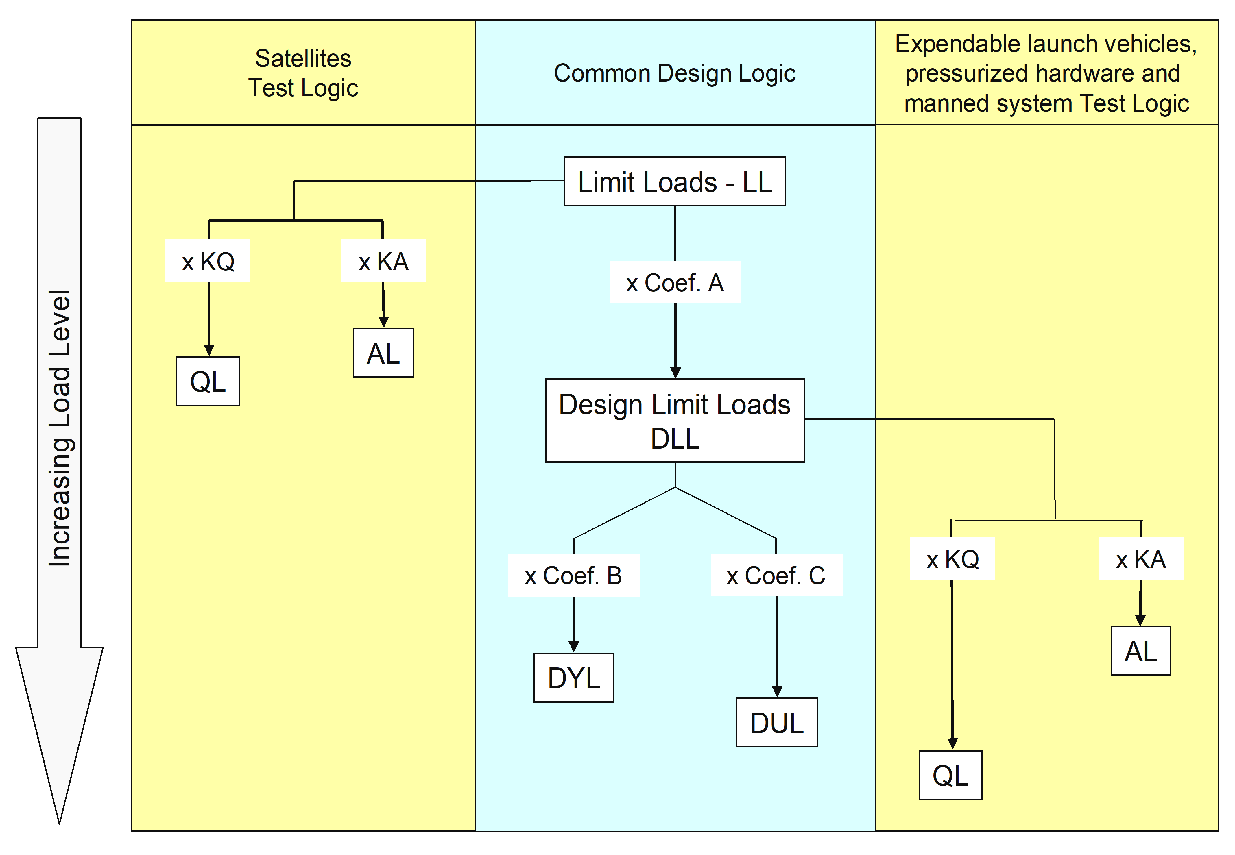 Figure 41: Logic for Factors of Safety application
TableTable 41: Relationship among (structural) factors of safety, design factors and additional factors
|
Coefficient
|
Satellite
|
Launch vehicles and pressurised hardware
|
Man-rated systems
|
|
Coef AorDesign factor
|
KQ x KP x KM
|
KP x KM
|
KP x KM
|
|
Coef B
|
FOSY x KLD
|
FOSY x KMP x KLD
|
FOSY x KLD
|
|
Coef C
|
FOSU x KLD
|
FOSU x KMP x KLD
|
FOSU x KLD
|
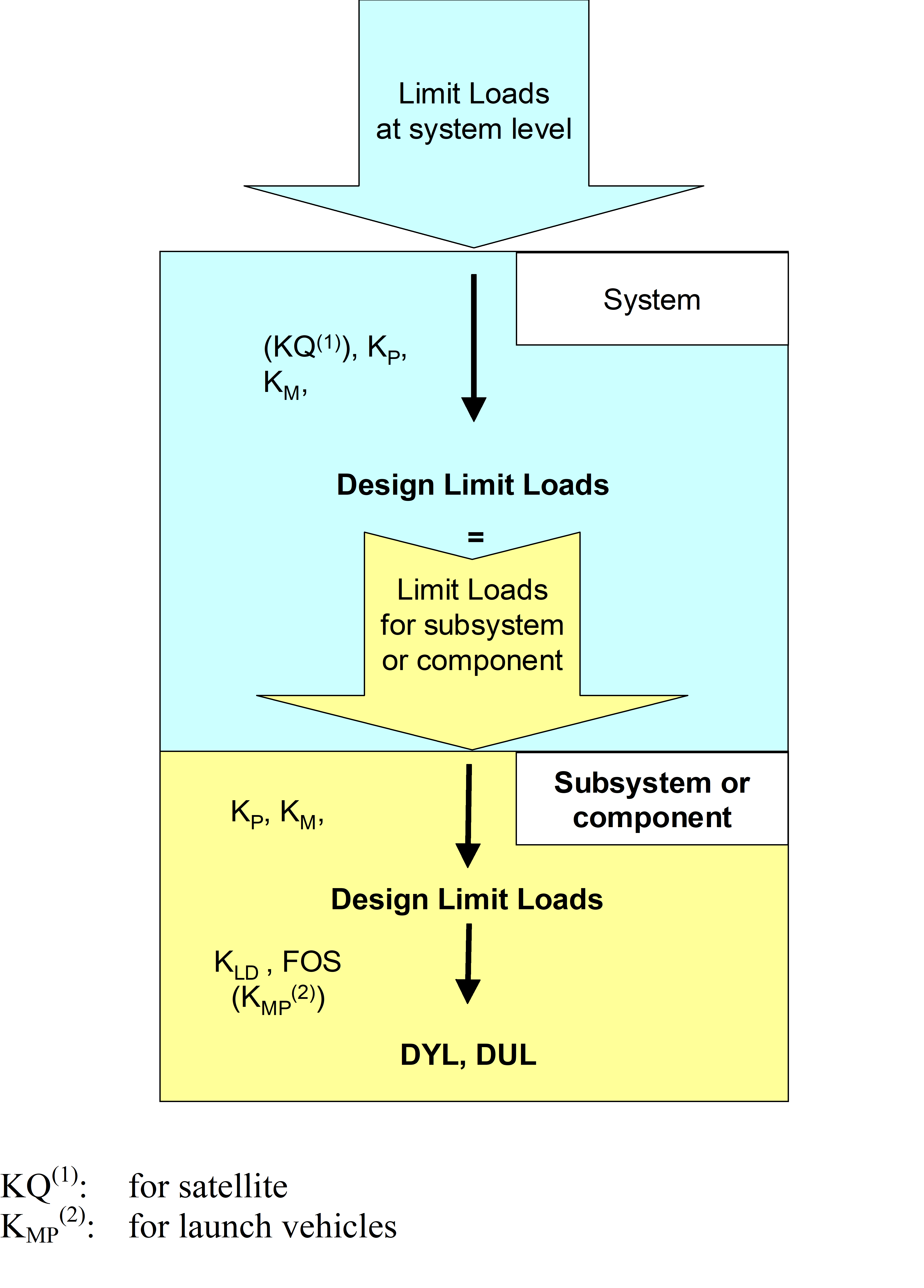 Figure 42: Analysis tree
Specific requirements for launch vehicles
The QL shall be defined with a corrected KQ.
- 1 The correction takes into account manufacturing variability and difficulties of having test conditions fully representative of flight conditions.
- 2 The commonly used method for defining the corrected KQ is presented in Annex A for information.
Factors values
Test factors
The test factors KQ and KA shall be selected from Table 42.
TableTable 42: Test factor values
|
Load type
|
Requirements
|
Comments
| |||||
|
Vehicle
|
KQ
|
KA
|
|
||||
|
Global flight loads
|
Satellite
|
1,25 a
|
1
|
|
|||
|
Launch vehicle
|
1,25corrected b
|
1 or Jp c
|
Typical value to be considered for dimensioning are Jp=1,05 to 1,1
| ||||
|
Man-rated S/C
|
Launch loads
|
1,4
|
1,2
|
|
|||
|
On orbit loads
|
1,5
| ||||||
|
Internal pressure
|
in conformance with ECSS–E-ST-32-02 i
|
Applicable for satellite and launch vehicles
| |||||
|
Dynamic local loads d
|
Satellite
|
1,25 a, e
|
1
|
|
|||
|
Launch vehicle
|
1,25 e
|
N/A
|
|
||||
|
Hoisting loads f
|
Satellite
|
2
|
N/A
|
|
|||
|
Hoisting loads g(fail safe)
|
Satellite
|
1
|
N/A
|
|
|||
|
Storage and transportation loads
|
Satellite
|
2
|
N/A
|
|
|||
|
Thermal loads h
|
Satellite
|
1
|
1
|
|
|||
|
Launch vehicle
|
1
|
1
| |||||
|
a A higher value can be specified by the Launch vehicle Authority or the customer.
| |||||||
Factors of safety
Metallic, FRP, sandwich, glass and ceramic structural parts
The factor of safety for metallic, FRP, sandwich, glass and ceramic structural parts shall be selected from Table 43.
For satellites and man-rated spacecraft, the factors provided in Table 43 shall apply for all additive loads including thermal induced loads.
For satellites and man rated spacecraft, when loads including thermal induced loads are relieving, both FOSU and FOSY shall be 1,0 or less.
See ECSS-E-ST-32.
For expendable launch vehicles, FOSU and FOSY associated with thermal induced loads shall be 1,0.
TableTable 43: Factors of safety for metallic, FRP, sandwich, glass and ceramic structural parts
|
Structure type
|
Vehicle
|
Requirements
| |||
|
FOSY
|
FOSU
|
FOSY verification by analysis only
|
FOSU verification by analysis only
| ||
|
Metallic parts
|
Satellite
|
1,1
|
1,25
|
1,25
|
2,0
|
|
Launch vehicle
|
1,1
|
1,25
|
See Note c
|
2,0
| |
|
Man-rated S/CLaunchOn Orbit
|
1,251,1
|
1,41,5
|
See Note c
|
See Note c
| |
|
FRP parts(away from discontinuities)
|
Satellite
|
N/A
|
1,25
|
N/A
|
2,0
|
|
Launch vehicle
|
N/A
|
1,25
|
N/A
|
2,0
| |
|
Man-rated S/CLaunchOn Orbit
|
N/AN/A
|
1,52,0
|
N/AN/A
|
See Note c
| |
|
FRP parts(discontinuities) a
|
Satellite
|
N/A
|
1,25
|
N/A
|
2,0
|
|
Launch vehicle
|
N/A
|
1,25
|
N/A
|
2,0
| |
|
Man-rated S/C
|
N/A
|
2,0 b
|
N/A
|
See Note c
| |
|
parts:
|
Satellite
|
N/A
|
1,25
|
N/A
|
2,0
|
|
Launch vehicle
|
N/A
|
1,25
|
N/A
|
2,0
| |
|
Man-rated S/C
|
N/A
|
1,4
|
N/A
|
See Note c
| |
|
Glass and ceramic structural parts
|
Satellite
|
N/A
|
2,5
|
N/A
|
5,0
|
|
Launch vehicle
|
N/A
|
See Note c
|
N/A
|
See Note c
| |
|
Man-rated S/C
|
N/A
|
3,0
|
N/A
|
See Note c
| |
|
a e.g.: holes, frames, reinforcements, steep change of thickness.
| |||||
Joints, inserts and connections
The factor of safety for joints, inserts and connections shall be selected from Table 44.
TableTable 44: Factors of safety for joints, inserts and connections
|
Structure type
|
Vehicle
|
Requirements
| |||
|
FOSY
|
FOSU
|
FOSY verification by analysis only
|
FOSU verification by analysis only
| ||
|
Joints and inserts: a
|
Satellite
|
N/AN/AN/A
|
1,25N/AN/A
|
N/A1,251,25
|
2,0N/A N/A
|
|
Launch vehicle
|
N/A1,11,1
|
1,25N/A N/A
|
N/A
|
N/A
| |
|
Man-rated S/C
|
See Note c
|
1,41,41,4
|
See Note c
|
See Note c
| |
|
Elastomer system and elastomer to structure connectionb
|
Satellite
|
See Note c
|
2,0
|
See Note c
|
See Note c
|
|
Launch vehicle
|
See Note c
|
2,0
|
See Note c
|
See Note c
| |
|
a These factors are not applied on the bolts preload – see threaded fasteners guidelines handbook (ECSS-E-HB-32-23).
| |||||
Buckling
The factor of safety for global and local buckling shall be selected from Table 45.
The factor of safety does not cover the knock down factors commonly used in buckling analyses - see Buckling handbook (ECSS-E-HB-32-24).
TableTable 45: Factors of safety for buckling
|
Vehicle
|
Requirements
| |||
|
FOSY
|
FOSU
|
FOSY verification by analysis only
|
FOSU verification by analysis only
| |
|
Satellite
|
See Note a
|
1,25
|
See Note a
|
2,0
|
|
Launch vehicle
|
N/A
|
1,25
|
See Note a
|
2,0
|
|
Man-rated S/C
|
See Note a
|
1,4
|
See Note a
|
N/A
|
|
a No commonly agreed value within the space community can be provided.
| ||||
Pressurized hardware
The factor of safety for pressurized hardware, engine feeding lines, and tank pressurisation lines shall be selected from Table 46 for the mechanical loads except the internal pressure.
- 1 For internal pressure loadings and loads combination, see ECSS-E-ST-32-02.
- 2 Pressurized hardware is defined in ECSS-E-ST-32-02.
TableTable 46: Factors of safety for pressurized hardware
|
Vehicle
|
Requirements
| |||
|
FOSY
|
FOSU
|
FOSY verification by analysis only
|
FOSU verification by analysis only
| |
|
Satellite
|
1,1
|
1,25
|
See Note a
|
See Note a
|
|
Launch vehicle
|
1,1
|
1,25
|
See Note a
|
See Note a
|
|
Man-rated S/C
|
1,25
|
1,4
|
See Note a
|
See Note a
|
|
a No commonly agreed value within the space community can be provided.
| ||||
ANNEX(informative)Qualification test factor for launch vehicles
In European launch vehicle programs, the QL to be implemented during the test is defined with a corrected KQ factor, derived by location and failure mode.
KQ is modified by correcting factors such as:
![]() for loading at yield load
for loading at yield load
![]() for loading at ultimate load
for loading at ultimate load
Taking into account the following points:
The actual thickness of qualification model versus thickness used for sizing. This is done through the use of the correcting factor Kmin which accounts for the effect of the thickness on the structure strength. It corresponds to the ratio of the thickness measured on the test specimen to the dimensioning thickness. Kmin is only applicable to metal structures, for other structures, Kmin=1.0 is used.
The adjacent structure's influence on the stress field between flight and test conditions. This is done through the use of the correcting factor Kadj which accounts for the influence of adjacent structures not present during static tests.
If the adjacent flight structures are simulated during static tests, Kadj=1,0 is used.
Else wise, Kadj is deduced as the ratio of the stress state (flight) computed in flight configuration to the stress state computed in test configuration (test) increased by the overflux factor used for the design.
![]() Effect of thermal gradient stress. This is done through the use of the correcting factor KT which is defined as the ratio of the increase in the stress due to the local thermal gradient to the stress corresponding to no local thermal gradient.
Effect of thermal gradient stress. This is done through the use of the correcting factor KT which is defined as the ratio of the increase in the stress due to the local thermal gradient to the stress corresponding to no local thermal gradient.
The effect of temperature on mechanical characteristics (Young’s modulus, strength…). This is done through the use of the correcting factor K which is the ratio of the mechanical characteristics considered at flight operating temperature C flight to the ones at test temperature C test.
![]() The influence of A-values for sizing and more probable values for the material constitutive of the qualification model. This is done through the use of the correcting factor K. If f(Ci) is the function translating the effect of characteristic Ci on the failure mode, the correcting factor K is defined as the ratio of f(Ci) for the characteristic value used for design to f(Ci) for the characteristic value of the tested specimen.
The influence of A-values for sizing and more probable values for the material constitutive of the qualification model. This is done through the use of the correcting factor K. If f(Ci) is the function translating the effect of characteristic Ci on the failure mode, the correcting factor K is defined as the ratio of f(Ci) for the characteristic value used for design to f(Ci) for the characteristic value of the tested specimen.
![]() If several characteristics C1, C2,… are affecting the considered failure mode, K is defined as:
If several characteristics C1, C2,… are affecting the considered failure mode, K is defined as:
![]() The correcting factors are defined and agreed with the customer.
The correcting factors are defined and agreed with the customer.
Bibliography
|
ECSS-S-ST-00
|
ECSS system – Description, implementation and general requirements
|
|
ECSS-E-HB-32-23
|
Space engineering – Threaded fasteners handbook
|
|
ECSS-E-HB-32-24
|
Space engineering – Buckling handbook.
|
|
NASA-STD-5001
|
Structural design and test factors of safety for spaceflight hardware (June 21, 1996)
|
|
A5-SG-1-X-10-ASAI(issue 5.12, April the 8th; 2003)
|
Structure design, dimensioning and test specifications
|