
Space product assurance
Durability testing of coatings
Foreword
This Standard is one of the series of ECSS Standards intended to be applied together for the management, engineering and product assurance in space projects and applications. ECSS is a cooperative effort of the European Space Agency, national space agencies and European industry associations for the purpose of developing and maintaining common standards. Requirements in this Standard are defined in terms of what shall be accomplished, rather than in terms of how to organize and perform the necessary work. This allows existing organizational structures and methods to be applied where they are effective, and for the structures and methods to evolve as necessary without rewriting the standards.
This Standard has been prepared by the ECSS-Q-ST-70-17C Working Group, reviewed by the ECSS Executive Secretariat and approved by the ECSS Technical Authority.
Disclaimer
ECSS does not provide any warranty whatsoever, whether expressed, implied, or statutory, including, but not limited to, any warranty of merchantability or fitness for a particular purpose or any warranty that the contents of the item are error-free. In no respect shall ECSS incur any liability for any damages, including, but not limited to, direct, indirect, special, or consequential damages arising out of, resulting from, or in any way connected to the use of this Standard, whether or not based upon warranty, business agreement, tort, or otherwise; whether or not injury was sustained by persons or property or otherwise; and whether or not loss was sustained from, or arose out of, the results of, the item, or any services that may be provided by ECSS.
Published by: ESA Requirements and Standards Division ESTEC, P.O. Box 299, 2200 AG Noordwijk The NetherlandsCopyright: 2018© by the European Space Agency for the members of ECSS## Change log
|
ECSS-Q-ST-70-17C
|
First issue
|
Introduction
Many different environmental factors can have an effect on coating durability for space applications. This includes in-orbit effects such as thermal cycling and particle radiation, as well as ground based effects such as cleaning, contamination and humidity. Space projects have typically been free to choose their own test requirements, based on a combination of existing standards and specific requirements for a given project. This approach can lead to ambiguous definitions about when a coating is “space qualified”. The supplier and customer often re-negotiate very general aspects of coating qualification for each new project. The intention of the present standard is to capture the best practice across the large range of existing national and international standards, in order to specify a minimum set of durability requirements for coating use in space applications. Information is also provided about some mission specific tests (including the atomic oxygen test, thermal ageing test, air-vacuum test and solar illumination test).
Scope
This standard specifies requirements for the durability testing of coatings most commonly used for space applications, i.e.:
Thin film optical coatings
Thermo-optical and thermal control coatings (the majority are paints, metallic deposits and coatings for stray light reduction)
Metallic coatings for other applications (RF, electrical, corrosion protection)
This standard covers testing for both ground and in-orbit phases of a space mission.
This standard includes coatings within off-the-shelf items
This standard specifies the types of test to be performed for each class of coating, covering the different phases of a space project (evaluation, qualification and acceptance)
This standard does not cover:
The particular qualification requirements for a specific mission
Specific functional testing requirements for the different coating classes
Test requirements for long term storage
Solar cell cover glass coatings
Surface treatments and conformal coatings applied on EEE parts
This standard may be tailored for the specific characteristic and constrains of a space project in conformance with ECSS-S-ST-00.
Normative references
The following normative documents contain provisions which, through reference in this text, constitute provisions of this ECSS Standard. For dated references, subsequent amendments to, or revision of any of these publications do not apply. However, parties to agreements based on this ECSS Standard are encouraged to investigate the possibility of applying the more recent editions of the normative documents indicated below. For undated references, the latest edition of the publication referred to applies.
|
ECSS-S-ST-00-01
|
ECSS system – Glossary of terms
|
|
ECSS-E-ST-10-12
|
Space engineering – Method for the calculation of radiation received and its effects, and a policy for design margins
|
|
ECSS-Q-ST-70-03
|
Space product assurance- Black anodizing of metals with inorganic dyes
|
|
ECSS-Q-ST-70-31
|
Space product assurance- Application of paints and coatings on space hardware
|
|
ISO 9211-4:2012
|
Optics and photonics – Optical coatings – Part 4: Specific test methods
|
|
ISO 2409:2007
|
Paints and varnishes: Cross cut test
|
|
ISO 4524-5:1985
|
Metallic coatings – Test methods for electrodeposited gold and gold alloy coatings – Part 5: Adhesion tests
|
|
ISO 3696:1987
|
Water for analytical laboratory use— Specification and test methods
|
|
ASTM B571-97(2013)
|
Standard practice for qualitative adhesion testing of metallic coatings
|
|
ASTM D1193-06(2011)
|
Standard specification for reagent water
|
Terms, definitions and abbreviated terms
Terms from other standards
For the purpose of this Standard, the terms and definitions from ECSS-S-ST-00-01 apply, in particular for the following term:
qualification
For the purpose of this Standard, the terms and definitions from ECSS-E-ST-10-12 apply, in particular for the following terms:
total ionising dose (TID)
total non-ionising dose (TNID)
Terms specific to the present standard
coating lot
set of substrates to which a coating is applied at the same time using the same chamber, bath or other equipment
Can also be called “coating run” or “coating batch”.
sample repair
localised re-application of a coating
sample de-treat or re-treat
complete removal and re-application of a coating onto an existing substrate
Abbreviated terms
For the purpose of this Standard, the abbreviated terms and symbols from ECSS-S-ST-00-01 and the following apply:
|
Abbreviation
|
Meaning
|
|
ESD
|
electrostatic discharge
|
|
GRM
|
geometrically representative model
|
|
ID
|
identification
|
|
IPA
|
isopropylalcohol
|
|
ITO
|
indium tin oxide
|
|
LID
|
laser induced damage
|
|
LIC
|
laser induced contamination
|
|
MEK
|
methyl ethyl ketone
|
|
NC
|
nonconformance
|
|
QA
|
quality assurance
|
|
RF
|
radio frequency
|
|
TCC
|
thermal control coatings
|
|
TID
|
total ionising dose
|
|
TNID
|
total non-ionising dose
|
|
TRL
|
technology readiness level
|
|
UV
|
ultraviolet
|
|
VUV
|
vacuum ultraviolet
|
Conventions
Coating process qualification is equivalent to the ECSS-Q-ST-70 meaning of process verification.
Nomenclature
The following nomenclature applies throughout this document:
The word “shall” is used in this Standard to express requirements. All the requirements are expressed with the word “shall”.
The word “should” is used in this Standard to express recommendations. All the recommendations are expressed with the word “should”.
It is expected that, during tailoring, recommendations in this document are either converted into requirements or tailored out.
The words “may” and “need not” are used in this Standard to express positive and negative permissions, respectively. All the positive permissions are expressed with the word “may”. All the negative permissions are expressed with the words “need not”.
The word “can” is used in this Standard to express capabilities or possibilities, and therefore, if not accompanied by one of the previous words, it implies descriptive text.
In ECSS “may” and “can” have completely different meanings: “may” is normative (permission), and “can” is descriptive.
The present and past tenses are used in this Standard to express statements of fact, and therefore they imply descriptive text.
Principles
General test approach
This standard gives a minimum set of tests to validate the coating process and also to give some meaningful results about exposure of the coating in its operating environment. However, full qualification of the coating for a specific space mission depends on the mission parameters, and it can be also necessary to define additional tests which are beyond the scope of the standard.
The practical severity of any test listed can be limited by the substrate (for example, it is not possible to perform the humidity test on hygroscopic substrates).
The tests are subdivided into degrees of severity, where appropriate. The standard gives condensed specification about the test method only. The full test procedure can be taken from appropriate international standards, or can be specified by mutual agreement between customer and supplier.
An individual test performed on a one-test-on-one-sample basis can give information about that single property of a coating reflected by that test and can be particularly useful for the supplier. In reality, coatings face a variety and range of severity of environmental exposures, and this is simulated by certain test sequences. Inevitably, such test sequences represent accumulative requirements.
Categories of use
For the space applications covered by this standard, the on-ground environment for all coatings is generally the same. The coatings are exposed only to a controlled environment (e.g. inside a cleanroom) and the coatings can be subjected to mild abrasion such as occurs with carefully controlled cleaning.
In-orbit, the following categories of use are specified in order to determine the severity of testing:
Category A: Coating is within a sealed, pressurised unit
Category B: Coating is exposed to vacuum but shielded inside spacecraft
Category C: Coating is exposed to vacuum with view to space
Coating classes
Links to other standards
For the present standard, the coatings are classified according to the type of durability testing. Technical requirements for the manufacture and acceptance testing of different coatings are also specified in various other ECSS standards. The link with the present standard is shown in Table 41.
Table 41: Other ECSS standards covering the manufacture and acceptance testing of different coating classes
|
Standard
|
Coating class according to ECSS-Q-ST-70-17
|
|
ECSS-Q-ST-70-03 “Black anodising of metals with in-organic dyes”
|
Thermo-optical and thermal control
|
|
ECSS-Q-ST-70-31 “Application of paints on space hardware”
|
Thermo-optical and thermal control
|
|
ECSS-Q-ST-70-14 “Corrosion”
|
Corrosion protection coatings
|
|
ECSS-Q-ST-70-71 “Data for the selection of space materials”
|
|
|
Anodizing
|
Thermo-optical and thermal control
|
|
Platings:
|
|
|
<1 μm
|
Test as for optical coatings
|
|
>1 μm
|
Thick metallic deposit
|
|
ECSS-E-ST-32-08 “Materials”
|
|
|
Anodizing
|
Thermo-optical and thermal control
|
|
Metallic coatings
|
Thick metallic deposits
|
|
Hard coatings
|
N/A
|
|
Thermal barriers, moisture barriers, coatings on CFRP
|
N/A
|
Thin film optical coatings
An optical coating is composed of a combination of thin film layers used to enhance transmission or reflection properties within an optical system. The performance of an optical coating is dependent on the number of layers, the thickness of the individual layers and the refractive index difference at the layer interfaces, and the properties of the substrate.
Optical coatings can be specified according to the function i.e. according to the nature of the principal modification to the surface properties that they realise. The main types of optical coating are identified in Table 42.
Table 42: Main types of optical coatings (adapted from ISO 9211-1:2010 definitions)
|
Principle function
|
Definition
|
Example of application
|
|
Reflecting
|
Coating increases the reflectance of an optical surface
|
Telescope mirror
|
|
Anti-reflecting
|
Coating reduces the reflectance of an optical surface
|
Coating on an instrument entrance window
|
|
Beam splitting
|
Coating separating the incidence flux into two beams
|
Partial reflector
|
|
Attenuating
|
Coating reducing the transmittance in non-selective manner
|
Neutral density filter
|
|
Bandpass or band rejection filter
|
Coating modifying the transmittance in a selective manner
|
Filter for imaging instrument
|
|
Selecting or combining long pass or short pass
|
Coating dividing the incidence flux into two or more beams each one covering a limited spectral region
|
Dichroic mirror, near infrared cut-off filter
|
|
Polarizing
|
Coating controlling the state of polarization of the emergent electromagnetic radiation
|
Polarizer
|
|
Phase changing
|
Coating controlling the phase change of the emergent electromagnetic radiation relative to the incident radiation
|
Phase retarder
|
|
Absorbing
|
Coating absorbing a specified value of the incident flux
|
Light trap
|
Thermo-optical and thermal control coatings (TCC)
TCCs are the elements of passive and active temperature control systems for temperature regulation of spacecraft. The thermal control coatings can be classified as follows:
Type I: true absorber (αs →1, ε →1);
Type II: solar reflector (αs →0, ε →1);
Type III: solar absorber (αs →1, ε →0);
Type IV: true reflector (αs →0, ε →0).
Examples of typical TCC coatings are:
Paints
Metallic coatings (e.g. for radiators)
Coatings for stray light reduction (e.g. black anodization)
Other metallic coatings
This class of coatings covers metallic coatings generally thicker than 1 μm. For example, this type of coating can be used for RF applications, electrical applications and corrosion protection.
Test philosophy
The overall test philosophy for any class of coating is depicted in Figure 41.
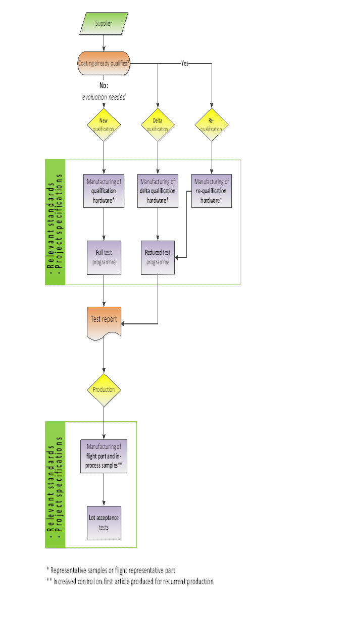 Figure 41: Test philosophy for durability testing of coatings
In the Figure 41, the following project phases are specified:
Evaluation
First approach to characterise new coatings at TRL 1 – 3 (see ECSS-E-AS-11)
Reduced test programme
Early screening to intercept weak coating before starting the core of the expensive qualification
The definition of the evaluation phase for new materials and processes is provided in ECSS-Q-ST-70.
New Qualification
New supplier, materials or process
Full test programme is necessary
First time the programme is performed (i.e. new qualification test plan)
The minimum qualification matrix guarantees:
Repeatability of the process is verified (e.g. by performing 2 coating runs for the qualification samples)
Early screening to intercept weak coating before starting the core of the expensive qualification
Essential tests that are unavoidable
Correct test sequence
Not too many resources in terms of:
Samples quantity,Number of tests,Campaign duration,Number of spectral measurements (avoid repetition and redundancies)Re-qualification
Re-qualification is implemented when there are major changes to existing process e.g.
Change of equipment,
Change of site,
Previous major anomalies
Process not implemented for prolonged period (typically more than 1 year)
Reduced test programme can be accepted, according to existing qualification test plan
Delta qualification
Delta qualification is implemented for minor changes in existing process e.g.
Minor changes to substrate material (e.g. alloys in different series )
Different environment
Different substrate geometry or surface preparation
Minor differences in coating design (e.g. layer thickness or number)
Minor changes to coating materials or process
Reduced test programme can be accepted, according to modification of existing qualification test plan.
Production phase
Coating is already fully qualified, and only lot acceptance tests are performed on samples selected from production lot.
Sample description
Evaluation phase
The evaluation phase is used for new coating designs. Samples replicate specific critical design features of the new coating e.g. interface materials, and substrate conditioning. Evaluation is optional if the risk level is limited.
Qualification phase
Qualification samples
Qualification samples are representative of the flight hardware, for materials, finishing and coating process.
Typically these are flat samples with standard thickness and shape in order to accommodate the standard testing requirements.
Geometrically representative model
A representative sample is necessary to complete the qualification when specific design features and operational environmental conditions can induce coating morphology heterogeneity, coating thickness variation and deformations of the substrate. For example, the following aspects need to be taken into account:
size and curvature of substrate
adhesion layers
primers
optical components with different coatings on each side
masking
grounding
holes for fastening
Special tests can be necessary (typically out of the scope of the standard). The qualification samples are adapted for this purpose.
Production phase
Flight coating process is always verified. If the flight object itself cannot be tested, then in-process samples are necessary, manufactured in the same coating run as the flight object. If necessary, witness samples can also be produced at the same time and batch, and stored.
Test programme
Evaluation
The following tests shall be performed in the evaluation phase:
- Adhesion
- Humidity
- Thermal cycling
Methods are specified in clause 6.
The substrate material and surface finish shall be representative of the final product.
The substrates position in the coating chamber shall be the same as for qualification.
Coatings chambers are mainly used for vapour and plasma deposition.
At least three samples shall be submitted to the evaluation testing.
Specific test sequence, conditions, measurements and performance criteria shall be agreed between supplier and customer.
For curved parts, some measurements (e.g. spectral performance) can be performed on flat samples.
Qualification
The coating qualification test programme shall be agreed with the customer.
The conditions and methods for coating qualification testing shall conform to the coating procurement specification.
The qualification testing shall not be considered valid until agreed by the customer.
The customer grants this validation based on the outcome of the durability tests and associated functional performance testing.
The following minimum set of qualification tests shall be performed according to the coating type:
- for optical coatings, as specified in Table 51,
- for TCC coatings, as specified in Table 52,
- for thick metallic coatings for RF and electrical applications and corrosion protection coatings, as specified in Table 53.
Test methods are defined in clause 6.
Visual inspection shall be performed before and after each test step, in compliance with requirements from clause 6.1.
Vacuum tests shall be performed for Category B and C.
Categories of use are defined in clause 4.2.
Vacuum test may be omitted for Category A subject to customer agreement.
For optical coatings, two coating lots shall be tested in order to verify the repeatability of the process in conformance with Table 51.
Additional tests for qualification shall be agreed with the customer.
Examples of such tests are shown in Annex D and depend on the space mission
Reduced test programme for qualification shall be agreed between customer and supplier.
Reduced test programme may be accepted for requalification or delta qualification.
The requirements for tests on a geometrically representative model shall be agreed with the customer.
An explanation about the geometrically representative model is given in Clause 4.5.2.2.
For metallic coatings > 1 μm a metallographic inspection shall be done on the geometrically representative model.
Table 51:Test matrix for qualification of optical coatings
|
Test
|
Method description
|
Sample 1
|
Sample 2
|
Sample 3
|
Sample 4
|
Sample 5
|
Sample 6
|
|
Performance
|
|
1, 5
|
1, 3
|
1, 3
|
1, 5
|
1, 5
|
1
|
|
Adhesion
|
Clause 6.2
|
6
|
4
|
4
|
6
|
6
|
|
|
Cleanability
|
Clause 6.5
|
2
|
|
|
|
|
|
|
Moderate abrasion
|
Clause 6.6
|
3
|
|
|
|
|
|
|
Humidity
|
Clause 6.3
|
4
|
|
|
2
|
2
|
|
|
Thermal vacuum and cycling
|
Clause 6.4
|
|
2
|
|
3
|
3
|
|
|
Particle and UV Radiation
|
Clause 6.7
|
|
|
2
|
4
|
4
|
|
|
Additional tests
|
in accordance with requirement 5.2i
|
|
|
|
|
|
|
|
NOTE 1: The numbers in the columns indicate the sequence(order) in which the tests are performed.For example, the test sequence for Sample1 is performance (1), cleanability (2), abrasion (3), humidity (4), performance (5), adhesion (6)
| |||||||
Table 52:Test Matrix for qualification of TCC coatings
|
Test
|
Method description
|
Sample 1
|
Sample 2
|
Sample 3
|
Sample 4
|
Sample 5
|
Sample 6
|
|
Performance
|
|
2
|
2, 5
|
2, 5
|
2, 5
|
2, 5
|
2
|
|
Thickness
|
Clause 6.8
|
1
|
1
|
1
|
1
|
1
|
1
|
|
Adhesion
|
Clause 6.2
|
4
|
7
|
7
|
7
|
7
|
|
|
Resistivity and ESD
|
Clause 6.9
|
3
|
6
|
6
|
6
|
6
|
|
|
Humidity
|
Clause 6.3
|
|
3
|
3
|
3
|
3
|
|
|
Thermal vacuum and cycling
|
Clause 6.4
|
|
4
|
4
|
4
|
4
|
|
|
Additional tests, including UV and particle radiation
|
in accordance with requirement 5.2i
| ||||||
|
NOTE1: The numbers in the columns indicate the sequence(order) in which the tests are performed.For example, the test sequence for Sample1 is thickness (1), performance (2), resistivity and ESD (3), adhesion (4)
| |||||||
Table 53:Test matrix for qualification of thick metallic coatings for RF and electrical applications, and corrosion protection coatings
|
Test
|
Method description
|
Sample 1
|
Sample 2
|
Sample 3
|
Sample 4
|
GRM
|
Sample 6
|
|
Thickness
|
Clause 6.8
|
1
|
1
|
1
|
1
|
1
|
1
|
|
Adhesion
|
Clause 6.2
|
2, 4, 6
|
2, 4, 6
|
2, 4 ,6
|
2, 4, 6
|
2,4,6
|
2
|
|
Humidity
|
Clause 6.3
|
3
|
3
|
3
|
3
|
3
|
|
|
Thermal vacuum and cycling
|
Clause 6.4
|
5
|
5
|
5
|
5
|
5
|
|
|
Additional tests
|
in accordance with requirement 5.2i
|
|
|
|
|
|
|
|
NOTE 1: The numbers in the columns indicate the sequence in which the tests are performed. For example, the test sequence for Sample1 is thickness(1), adhesion (2), humidity (3), adhesion (4), thermal vacuum and cycling (5), adhesion (6)
| |||||||
Production
Acceptance tests for production shall be agreed with the customer.
For heat quench test into air on metallic platings, refer to requirement 4.3.10f of ECSS-Q-ST-70-71.
For production of previously qualified optical coatings the following conditions shall be met:
- the minimum set of lot acceptance tests specified in Table 54 are performed on a minimum of two samples selected from the flight lot;
- one untested sample from the flight lot is retained as a reference sample;
- visual inspection is performed before and after each test as a test result evaluation;
- reduced spectral performances are agreed between customer and supplier in case of complex measurements and redundancies.
Acceptance tests for paints shall be performed in accordance with ECSS-Q-ST-70-31.
Acceptance tests for black anodization shall be performed in accordance with ECSS-Q-ST-70-03.
Table 54:Test Matrix for Production of Optical Coatings
|
Test
|
Method
|
Sample 1
|
Sample 2
|
Sample 3
|
|
Performance
|
|
1
|
1, 6
|
1
|
|
Adhesion
|
Clause 6.2
|
2
|
7
|
|
|
Cleanability
|
Clause 6.5
|
|
2
|
|
|
Moderate abrasion
|
Clause 6.6
|
|
3
|
|
|
Humidity
|
Clause 6.3
|
|
4
|
|
|
Thermal vacuum and cycling
|
Clause 6.4
|
|
5
|
|
Sample definition for a test programme
Samples shall be representative of the flight hardware for the following aspects:
- same substrate material
- same surface finishing
- same coating
- same supplier
- same production facility and coating chamber
- same manufacturing process
For the requirement 5.4a.2 surface finishing includes for example polishing, etching or cleaning.
The need for a geometrically representative model or additional samples with specific geometry shall be agreed with the customer before the start of the coating qualification programme.
Samples dimensions and geometries shall be compatible with the test methods.
Handling and storage of qualification samples
Prior to and during the testing samples shall be protected from degradation due to storage and handling.
- 1 Handling precautions are commensurate with the coating family. For example, suitable gloves and face masks are worn during handling to protect sensitive optical samples.
- 2 Storage after test depends on project specifications.
- 3 Some coatings e.g. silver are susceptible to tarnishing during storage and specific protective measures are necessary.
Traceability of samples shall be maintained.
Test acceptance criteria
After the completion of each test, the coating shall be accepted when the following criteria are met:
- no visual degradation of the coating;
- no delamination or adherence loss;
- thickness conforms to requirements;
- performance measurements comply with coating specification.
- 1 Degradation can be colour change, cracks, pits.
- 2 Additional microscope inspection can be used for suspected degradation.
- 3 Specific acceptance criteria can also be defined for some tests.
- 4 For some test steps, a partial set of measurements can be agreed with the customer, to save time and effort (see Annex D).
- 5 Coating specification is included in the qualification plan (see Annex A).
Test methods, conditions and measurements
Visual inspection
Samples shall be cleaned and inspected before and after each test step to verify that the defects are in conformance with the coating specification.
During visual inspection no degradation shall be evident compared to the initial inspection.
The inspection method shall be stated in the Coating Qualification test Report in conformance with DRD from Annex B.
- 1 A method for visual inspection of optical coatings is defined in Annex C of ISO 9211-4:2012.
- 2 Microscope images can be taken in case of suspected anomaly.
- 3 Illumination conditions are important (e.g. use of UV light, or blue light).
- 4 For coatings within electronic boxes, magnification is important to detect possible defects related to electrical shorts.
- 5 The following standards provide further guidelines for visual inspection of coatings:
- ISO 10110-7:2008 and ISO 14997:2011
- ISO 21227-1 Part 1 (2003)
- ASTM B488-11 for gold plating
Adhesion
The adhesion test shall be selected according to the coating and substrate thickness.
For optical coatings, the adhesion test shall be performed according to ISO 9211-4:2012, Conditioning method 2, Adhesion, Degree of severity 01.
Degree of severity 01 corresponds to a rate of tape removal slow, (2 - 3) s per 25 mm.
For paints the adhesion test shall be performed in compliance with the requirements in ISO 2409:2007.
- 1 Clause 6.2.6 of ISO 2409:2007 specifies test with pressure sensitive tape.
- 2 The distances between the scratches depends on the layer thickness.
For ceramic coatings the adhesion test shall be performed in compliance with the requirements in ISO 2409:2007, without cross cut.
For metallic coatings, the adhesion test method shall be selected from Table 1 of ASTM B571-97(2013).
For gold electrolytic coatings the adhesion test method shall be selected from ISO 4524-5:1985.
The adhesion method used shall be specified in the qualification test plan in conformance with DRD from Annex A.
If the substrate is not compatible with the adhesion test then the test shall be adapted, and subject to agreement with the customer.
Particularly long-wavelength optical coatings become progressively more fragile with increasing multilayer thickness.
The strength of the adhesion tape shall be verified as follows:
- by supplier data, or
- by test.
- 1 Tapes commonly used for space coatings are specified in Annex E.
- 2 An example of a standard for measuring the peel and pull-off strength of coatings is ECSS-Q-ST-70-13 or ISO 29862:2007.
Adhesion tape exceeding the shelf life shall be re-lifed by test before use.
Humidity and temperature
The samples shall be placed in a chamber at ambient pressure.
The chamber temperature shall be increased from ambient temperature to a minimum temperature in the range (40 – 50) °C.
The minimum requirement encompasses best practice.
Relative humidity shall be higher than or equal to 90 %.
If the coating or substrate is not compatible with the humidity level then the test shall be agreed with the customer.
- 1 For example, the test can be performed for a longer period at lower humidity level.
- 2 Hygroscopic substrates can be incompatible with this test.
The duration of the test shall be: - 24 hours for optical coatings and thin metallic coatings under 1 μm,
- 7 days to 10 days for TCC coatings and thick metallic deposits over 1 μm.
- 1 In the context of this standard, the humidity test is a quality control test to check mechanical resistance, and stress in the coating (see D.2 from Annex D). Extended testing can be performed to simulate other ageing effects.
- 2 See ECSS-Q-ST-70-14 for corrosion testing requirements.
Purified water shall be used, in accordance with requirements for ISO Grade II from ISO 3696:1987.
Water purity requirements are defined in ASTM D1193-06(2011) or ISO 3696:1987.
Water condensation on the surface of the coating shall be prevented.
If the coating specification defines specific environmental conditions, the test shall be adapted to these conditions in agreement with the customer.
- 1 For example, requirements on chemical vapors.
- 2 Simulation of long term storage is project specific and additional humidity testing can be performed.
Thermal vacuum and cycling
A minimum of 25 thermal cycles shall be performed, with at least the first five cycles performed under vacuum.
Five cycles are performed in vacuum, because it is most commonly accepted that degradation (such as delamination) of coatings in vacuum typically occurs within the first few cycles e.g. due to stress generated by thermal expansion mismatch and moisture release.
For the vacuum cycles, the vacuum level shall be < 5 x 10⁻⁵ hPa.
For metallic coatings > 1 μm, the vacuum shall be omitted
It is commonly accepted that the adhesion test puts more stress on these coatings than stresses induced by vacuum.
Additional cycles shall be performed according to the project specification.
The additional cycles are typically performed to simulate ageing effects.
The temperature range and margins shall cover the mission specifications, including all phases on ground and in-orbit.
The rate of temperature change shall be less than 10 K per minute.
Maximum rate specified in order to avoid thermal shock.
The temperature shall be monitored to verify that the specified temperature is achieved on the samples.
A similar witness sample can be used if it is not possible to place a sensor directly on the qualification sample.
The minimum dwell time shall be at least 15 minutes at each temperature extreme.
The test method and set-up shall be specified.
Method for thermal cycling testing is defined in ECSS-Q-ST-70-04.
Cleaning and solvent compatibility
For optical coatings, the following test shall be applied:
- wipe the sample with the test solvent for a minimum time of two minutes;
- upon finishing the wiping allow the solvent to evaporate without forced drying;
- remove any resultant stains from the surface by wiping the coating to a clean stain free condition with a clean cloth moistened in solvent.
More information can be found in MIL-C-48497A (1980).
Test solvents shall be agreed between customer and supplier.
- 1 These solvents are normally agreed taking into account any restrictions due to compatibility with substrate.
- 2 Common test solvents are deionized water, acetone, MEK, IPA, methyl/ethyl alcohol
In case the coating supplier has its own cleaning test method different to the test method specified in requirements from 6.5a to 6.5b, this cleaning method shall instead be applied on the sample between three and five times.
Abrasion
The abrasion resistance test for optical coatings shall be done in conformance with the requirements from ISO 9211-4:2012, Conditioning method 01, severity degree 01
The abrasion test may be omitted, if it is agreed with customer that these are sensitive coatings which cannot be cleaned during the life cycle.
The restriction on cleanability shall be clearly stated in the coating documentation.
Particle and UV Radiation
An analysis shall be used to identify respective TID, TNID depth profile for each radiation type through the thickness of the coating, and corresponding test parameters.
Corresponding test parameters can include wavelength , energy of particle and fluence.
Test specifications shall cover the worst case environment derived from the results of the analysis specified in 6.7a.
- 1 Worse case environment includes TID/TNID dose profile.
- 2 For particle radiation, refer to ECSS-E-ST-10-12 for methods for calculations of radiation received.
- 3 For particle and UV radiation testing refer to ECSS-Q-ST-70-06.
The radiation test shall be performed using fully flight representative substrates with known radiation characteristics for the mission environment.
Potential effects on the substrate due to acceleration factor shall be assessed in order to avoid overtesting.
For very low dose the radiation test need not be performed if so agreed with the customer.
For example, in category A and B.
For radiation tests on coatings sensitive to annealing effects, the procedure for the performance measurements shall be agreed with the customer.
- 1 For example, the solar absorptance of paints can recover after re-exposure to air.
- 2 Performance measurements under vacuum can be used to avoid annealing effects.
- 3 Samples measured in ambient air can be stored in vacuum bags prior to the performance measurements.
Thickness measurement
The method for measurement of the thickness shall be specified in the validation test report.
- 1 The thickness of paints and insulating coatings can be measured using the eddy current method specified in ISO 2360:2003, or by micro-section.
- 2 ISO 3497:2000 specifies a method for measurement of metallic coatings using X-ray fluorescence.
- 3 ISO 3882:2003 provides a list of methods for thickness measurements according to the metallic substrate.
Surface resistivity and ESD
The surface resistivity measurements and ESD characterization shall be agreed with the customer.
The test method shall be specified in the validation test report.
- 1 ECSS-E-ST-20-06 provides a test method for ESD characterization.
- 2 ISO 15091:2012 provides a test method for the surface resistivity measurement of paints.
- 3 ASTM D5213-12 provides a test method for the surface resistivity measurement of polymeric resin films.
- 4 ASTM D257-14 provides a test method for the surface resistivity measurement of insulating coatings.
- 5 For insulating coatings, a breakdown voltage test is performed when the surface resistivity if out of specification. Example of the test is found in ISO 2376:2010.
- 6 ASTM B193-16 provides a test method for the surface resistivity measurement of conductive coatings.
Quality assurance
Documentation
The coating qualification test programme shall be documented in a Coating Qualification Test Plan in conformance with the DRD from Annex A, to be agreed with the customer.
The qualification test plan can be incorporated directly into the RFA
The results of the coating qualification tests shall be documented in the Coating Qualification Test Report in conformance with the DRD from Annex B, to be agreed with the customer.
The results of the coating acceptance tests shall be documented in the Coating Acceptance Test Report in conformance with the DRD from Annex C, to be agreed with the customer.
Maintenance of process qualification
The supplier shall inform the customer about all modifications implemented in the process.
- 1 For recurrent production, the customer can organize a regular material and process review (e.g. every 3 years) to confirm that no modification of the process or process application has been implemented or if implemented, that the changes have no impact on the qualification status.
- 2 See ECSS-Q-ST-20 for requirements about certification of operators.
Delta qualification and re-qualification testing shall be agreed between the customer and supplier.
See clause 4.4 for description of delta or re-qualification.
A supplier process audit shall be performed for new suppliers prior to the start of qualification testing.
ANNEX(normative)Coating qualification test plan - DRD
DRD identification
Requirement identification and source document
This DRD is called from ECSS-Q-ST-70-17, requirement 7.1a.
Purpose and objective
The coating qualification test plan is used to ensure that all relevant information related to the qualification testing of the coating is documented in sufficient detail for the customer to agree on the implementation of the test programme.
Expected response
Scope and content
The coating qualification test plan shall include the following information:
- Coating specification
- Quantity and shape of samples
- Quantity and shape of geometrically representative model
- Qualification tests sequence versus involved samples
- Short tests description, including the adhesion test method
- Success criteria
For qualification tests sequence a matrix can be used.
Special remarks
None.
ANNEX(normative)Coating qualification test report - DRD
DRD identification
Requirement identification and source document
This DRD is called from ECSS-Q-ST-70-17, requirement 7.1b.
Purpose and objective
The purpose of the coating qualification test report is to ensure that all relevant information related to the results of the qualification testing of the coating is documented in sufficient detail for the customer to agree on the qualification.
Expected response
Scope and content
The coating qualification test report shall include the following information:
- Reference to coating specification
- Coating identification
- Coating deposition run
- Deposition system ID
- Substrate material
- Quantity and shape of samples
- Quantity and shape of geometrically representative model
- Site responsible of qualification campaign
- Test equipment brand, name, location and measurement purpose
- Qualification tests sequence versus involved samples
- Short tests description
- Single Tests result (PASS or FAIL CRITERIA)
- Performance measurement data pre and post environmental tests with analysis
- Conclusion: Qualification PASS or FAIL
For qualification tests sequence a matrix can be used.
Special remarks
None.
ANNEX(normative)Coating acceptance test report - DRD
DRD identification
Requirement identification and source document
This DRD is called from ECSS-Q-ST-70-17, requirement 7.1c.
Purpose and objective
The purpose of the coating acceptance test report is to ensure that all relevant information related to the results of the acceptance testing of the coating is documented in sufficient detail for the customer to agree on the acceptance.
Expected response
Scope and content
The coating acceptance test report shall include the following information:
- List of coated parts with part reference
- Reference to Coating Specification
- Coating deposition lot
- Quantity
- Control report for Acceptance test set and relative results
- Nonconformance Report for NC parts and defect descriptions
- Performance measurements
- Statement of Declaration or Certificate of Conformity
- Signature or Stamp of QA manager and of inspectors
Special remarks
None.
ANNEX(informative)Additional information about test methods
Functional performance testing
Functional performance testing is an integral part of the durability testing, in order to determine the success of the durability tests. The specific tests depend on the coating application and are therefore not part of this standard. However the information in Table D-1 gives typical types of performance testing for the different coating classes.
Table: Typical performance testing
|
Coating class
|
Typical performance testing
|
|
Optical coatings
|
Transmission and reflectance for:
|
|
Optical coatings
|
Transmission or reflectance for:
|
|
TCC coatings
|
Solar absorptance (see ECSS-Q-ST-70-09)
|
|
Other metallic coatings
|
Corrosion resistance (see ECSS-Q-ST-70-14)
|
|
1) The partial test sequence can be used on selected samples to enable the functional testing to be performed in the most timely and cost effective manner.
| |
Humidity
Coatings for space applications are typically stored in a controlled atmosphere on ground (e.g. cleanroom or nitrogen purge). Nevertheless, a short term humidity test (e.g. 24 hours, 7 or 10 days at relative humidity higher than 90 %) is used as a simple quality control test to check the mechanical resistance and stress in the coating. The goal of this test is to accelerate the ageing process so that meaningful data can be acquired in a short period of time. There is no firm scaling factor that correlates the duration of the test with the life in a given environment, because the degradation mechanism that takes place in highly accelerated testing is not the same one that causes the long term degradation. However, the test is a common technique to accelerate the ageing process simply and in a repeatable manner and to evaluate if a coating is reasonably durable. It is important that no condensation occurs on the coating during the cooling phase. This test is not performed at all if the substrate or coating is hygroscopic, and for some coatings, it is necessary to eliminate traces of water absorbed during the humidity test (e.g. by leaving at room temperature for a given period of time) before starting the thermal cycling test. For simulation of long term storage of coatings, or exposure to more extreme environments, extended humidity testing can be necessary, depending on the mission requirements.
Thermal cycling
The goal of the thermal cycling test is to check the mechanical resistance of the coating under extremes of temperature and vacuum. Typically an optical coating fails during the first few cycles (usually due to thermal expansion coefficient mismatch). Therefore, a limited number of cycles are performed in the first instance as a quality control. Of course, this can be far short of the actual cycles an optical component encounters in orbit. If fatigue related issues are critical, then extended testing is necessary. This needs to be assessed depending on the mission requirements. The main disadvantage of thermal vacuum cycling is the very high cost and long schedule implications (the duration of the test can be several weeks). It is important to ensure that the optic reaches the actual test temperature, and this takes more time for large, glass optics which are not thermally conductive. Sometimes, it is possible to replace some of the vacuum cycles with thermal cycles at atmospheric pressure.
An alternative thermal shock test can be used to quickly assess the quality of a new coating (e.g. repetitive immersion in LN2 and hot solvent). The advantage of thermal shock testing is increased cycling speed. However it is more severe, because:
It is subject to atmospheric pressure conditions which can form ice condensate and exert disproportionate stress on the coatings.
It is uncontrolled with time and excursion temperature rates.
Thermal endurance (ageing)
Thermal ageing testing is used to simulate prolonged exposure of the coating to high or low temperature.
A classical approach of thermal ageing (maximum temperature for the mission duration) can be too severe, especially if materials are operating close to their limit. An alternative test approach is based on a two-step temperature ageing programme.
A lower temperature first phase is performed where the samples are thermally aged such that a pre-conditioning occurs.
This first exposure is followed by a second exposure at a higher temperature (e.g. +20 °C and then +50 °C higher) which encompasses the time or temperature mission profile during the operational phase. This approach is based on a general engineering rule of thumb that a temperature increase of 10 °C leads to a factor 2 increase in chemical reaction speeds. Again relevant properties and material analysis are performed to assess the long term stability of the test items through intermediate inspection points.
Outgassing
For the outgassing test see ECSS-Q-ST-70-02.
Particle and UV Radiation
Radiation test parameters depend on the mission environment and the configuration of the optical system. For example, an optical component embedded within an instrument can be shielded to a greater extent than an optic exposed directly to space. The category of use for the component is taken into account and a radiation analysis is performed to predict the radiation level. To define the radiation test parameters, the absorbed dose for a given energy is estimated based on the thickness of the coating. In general, particle radiation testing is performed with the actual radiation species encountered in the space environment (e.g. electrons, protons). However the energy of the particles during the test is not the same as the energies in space, because the main interest is the energy which is absorbed. Simulation of the total absorbed dose using gamma radiation is usually only of very limited use as most of the radiation is not be absorbed in the thin coating.
Other factors to include when performing the radiation test are:
Annealing effects (the spectral measurements are made in-situ or as soon as possible after the exposure). Vacuum bags can be used to minimise expose of samples to air after irradiation.
Degradation of the substrate (the test is always be performed using a substrate which has known degradation characteristics with respect to radiation).
Chosen test facilities depends on the dose profile and dominant particle.
Margin of safety is agreed with the customer depending on the application (typically MOS = 2).
Optical coatings are often declared by suppliers as “radiation resistant” based on previous heritage. In this case, it is important to prove that the materials and general composition of the coating have not changed, and that the radiation environment for the mission envelopes the previously tested coating.
General requirements for particle and UV radiation testing of materials are defined in ECSS-Q-ST-70-06.
Atomic oxygen
Atomic oxygen testing is applicable for coatings exposed directly to the space environment in Low Earth Orbit. In general, most inorganic and metallic coating materials can be considered as atomic oxygen resistant. However, substrates made from sensitive materials can still be exposed to atomic oxygen if there are defects or cracks in the coating, and erosion can be increased due to undercutting. Examples of coating systems which can be potentially susceptible are protected silver coatings (for example on mirror substrates or radiator fins), or thin protective coatings on polymeric films (e.g. ITO or on Kapton).
The aim of the atomic oxygen test is to measure the potential degradation of critical characteristics of the coating system. Often it is not possible to perform a “life-test”.
Air-vacuum testing
For some types of porous coating, the spectral response can shift to lower wavelengths during the transition from air to vacuum. This can have serious implications for the performance of optical instruments operating in vacuum, and can go undetected if durability testing has only be performed on-ground at atmospheric pressure. Therefore it is always a good practice to perform a functional testing of the coating under vacuum for critical applications. For small optics, a vacuum cell can be incorporated into the sample compartment of a standard bench-top spectrophotometer, and spectral scans are continuously taken as the vacuum cell is evacuated. For larger samples, or measurements on flight hardware, a purpose built vacuum facility can be used, with a means to adapt the spectrophotometer onto the facility.
Laser induced damage testing
LID and LIC testing is applicable for optical coatings which are exposed to high power laser beams. For LIC testing, the coating is exposed to the laser beam in the presence of organic materials, and the resulting transmission loss is measured. For LID testing, the coating is exposed to multiple laser shots with varying intensity until damage occurs, in order to measure the so-called laser induced damage threshold of the coating in vacuum.
Contamination effects
Molecular contamination can be deposited onto optical coatings due to vacuum outgassing from nearby organic materials on the spacecraft. In general, this effect is not associated with the durability of the coating itself but rather the external environment. However, in some cases the coating design can change the affinity of the molecules to stick to the surface, especially in the presence of UV radiation. Testing can then be performed to assess the response of different types of coating under controlled contamination flux.
Solar illumination
In some non-nominal operating modes, the spacecraft attitude can deviate, pointing the optical axis towards the sun. After reflection on M1 and M2 mirrors, solar fluxes are focused on the telescope front and rear cavity, reaching the detectors. The solar spot received by the instrument elements is defined by its heat flux density, surface area and the scrolling rate. The objective of the solar illumination test is to confirm that exposed coatings are able to withstand the short term temperature increase induced by this solar illumination. The testing conditions are given by the thermal simulations and the project specification.
ANNEX(informative)Tape strengths and type for adhesion testing
The typical types and typical strengths of tapes used for adhesion testing are provided in the Table E-1:
Table: Typical tapes used for adhesion testing of space coatings
|
Tape type
|
Adhesion strength (on steel) **
|
Application
|
|
3M 810
|
2,5 N/cm
|
Optical
|
|
3M 600
|
3,0 N/cm
|
Optical
|
|
3M 250
|
7 N/cm
|
Metallic deposit
|
|
3M 995
|
4,5 N/cm
|
Metallic deposit
|
|
3M P92(*)
|
2,8 N/cm
|
Silicone paints
|
|
Scotch® Filament Tape 8915
|
6,5 N/cm
|
Metallic deposit
|
|
Permacel P224
|
4,2 N/cm
|
Paints, metallic deposits, other general coatings
|
|
* A silicone based tape is used for adhesion testing of silicone paints. See ECSS-Q-ST-70-13
| ||
Bibliography
|
ECSS-S-ST-00
|
ECSS system – Description, implementation and general requirements
|
|
ECSS-E-ST-20-06
|
Space engineering – Spacecraft charging
|
|
ECSS-E-ST-32-08
|
Space engineering - Materials
|
|
ECSS-E-AS-11
|
Adoption Notice of ISO 16290, Space systems – Definition of Technology Readiness Levels (TRLs) and their criteria assessment
|
|
ECSS-Q-ST-70
|
Space product assurance – Materials, mechanical parts and processes
|
|
ECSS-Q-ST-70-02
|
Space product assurance – Thermal vacuum outgassing test for the screening of space materials
|
|
ECSS-Q-ST-70-04
|
Space product assurance – Thermal testing for the evaluation of space materials, processes, mechanical parts and assemblies
|
|
ECSS-Q-ST-70-06
|
Space product assurance – Particle and UV radiation testing for space materials
|
|
ECSS-Q-ST-70-09
|
Space product assurance- Measurements of thermo-optical properties of thermal control materials
|
|
ECSS-Q-ST-70-13
|
Space product assurance – Measurements of the peel and pull-off strength of coatings and finishes using pressure-sensitive tapes
|
|
ECSS-Q-ST-70-14
|
Space product assurance- Corrosion
|
|
ECSS-Q-ST-70-71
|
Space product assurance –Materials, Processes and their data selection
|
|
ASTM D5213-12
|
Standard Specification for Polymeric Resin Film for Electrical Insulation and Dielectric Applications
|
|
ASTM D257-14
|
Standard Test Methods for DC Resistance or Conductance of Insulating Materials
|
|
ASTM B193-16
|
Standard Test Method for Resistivity of Electrical Conductor Materials
|
|
ASTM B488-11
|
Standard Specification for Electrodeposited Coatings of Gold for Engineering Uses
|
|
ISO 9211-1:2010
|
Optics and photonics - Optical coatings - Part 1: Definitions
|
|
ISO 2360:2003
|
Non-conductive coatings on non-magnetic electrically conductive basis materials - Measurement of coating thickness - Amplitude-sensitive eddy-current method
|
|
ISO 2376:2010
|
Anodizing of aluminium and its alloys - Determination of electric breakdown potential
|
|
ISO 3497:2000
|
Metallic coatings - Measurement of coating thickness - X-ray spectrometric methods
|
|
ISO 3882:2003
|
Metallic and other inorganic coatings - Review of methods of measurement of thickness
|
|
ISO 10110-7:2008
|
Optics and photonics - Preparation of drawings for optical elements and systems - Part 7: Surface imperfection tolerances
|
|
ISO 14997:2011
|
Optics and photonics- Test methods for surface imperfections of optical elements
|
|
ISO 15091:2012
|
Paints and varnishes- Determination of electrical conductivity and resistance
|
|
ISO 21227-1:2003
|
Paints and varnishes - Evaluation of defects on coated surfaces using optical imaging - Part 1: General guidance
|
|
ISO 29862:2007
|
Self adhesive tapes - Determination of peel adhesion properties
|
|
MIL-C-48497A (8 September 1980)
|
Military specification: coating, single or multilayer, interference: durability requirements for
|