
Space engineering
CANbus extension protocol
Foreword
This Standard is one of the series of ECSS Standards intended to be applied together for the management, engineering and product assurance in space projects and applications. ECSS is a cooperative effort of the European Space Agency, national space agencies and European industry associations for the purpose of developing and maintaining common standards. Requirements in this Standard are defined in terms of what shall be accomplished, rather than in terms of how to organize and perform the necessary work. This allows existing organizational structures and methods to be applied where they are effective, and for the structures and methods to evolve as necessary without rewriting the standards.
This Standard has been prepared by the ECSS-E-ST-50-15C Working Group, reviewed by the ECSS Executive Secretariat and approved by the ECSS Technical Authority.
Disclaimer
ECSS does not provide any warranty whatsoever, whether expressed, implied, or statutory, including, but not limited to, any warranty of merchantability or fitness for a particular purpose or any warranty that the contents of the item are error-free. In no respect shall ECSS incur any liability for any damages, including, but not limited to, direct, indirect, special, or consequential damages arising out of, resulting from, or in any way connected to the use of this Standard, whether or not based upon warranty, business agreement, tort, or otherwise; whether or not injury was sustained by persons or property or otherwise; and whether or not loss was sustained from, or arose out of, the results of, the item, or any services that may be provided by ECSS.
Published by: ESA Requirements and Standards Division ESTEC, P.O. Box 299, 2200 AG Noordwijk The Copyright: 2015© by the European Space Agency for the members of ECSS## Change log
|
ECSS-E-ST-50-15C
|
First issue
|
Introduction
This standard specifies requirements for the use of the CAN (Controller Area Network) data bus in spacecraft onboard applications. These requirements extend the CAN Network specification to cover the aspects required to satisfy the particular needs of spacecraft data handling systems. This standard is one of a series of ECSS standards relating to data link interfaces and communication protocols e.g. MIL-STD-1553 and ECSS-E-ST-50-5x Space Wire.
In order to provide a uniform set of communication services across these standards the CCSDS Spacecraft Onboard Interface Services (SOIS) Subnetwork Recommendations have been applied as driving requirements for protocol specification.
The CAN Network has been successfully used for three decades in automotive and critical control industry. In particular, its use in applications that have demanding safety and reliability requirements, or operate in hostile environments have similarities to spacecraft onboard applications.
The CAN Network is being adopted for a variety of space applications and care has therefore been taken during the drafting of this standard to include existing experience and feedback from European Space industry.
In addition to the CAN Network data link specifications, this standard also specifies the optional use of the CANopen standard as an application layer protocol operating over CANbus.
The set of CANopen specifications comprises the application layer and communication profile as well as application, device, and interface profiles. CANopen provides very flexible configuration capabilities.
Scope
This standard is applicable to spacecraft projects that opt to use the CAN Network for spacecraft on-board communications and control. It also defines the optional use of the CANopen standard as an application layer protocol operating in conjunction with the CAN Network data link layer.
This standard does not modify the basic CAN Network specification and complies with ISO 11898-1/-2:2003. This standard does define protocol extensions needed to meet spacecraft specific requirements.
This standard covers the vast majority of the on-board data bus requirements for a broad range of different mission types. However, there can be some cases where a mission has particularly constraining requirements that are not fully in line with those specified in this standard. In those cases this standard is still applicable as the basis for the use of CAN Network, especially for physical layer and redundancy management.
This standard may be tailored for the specific characteristic and constrains of a space project in conformance with ECSS-S-ST-00.
Normative references
The following normative documents contain provisions which, through reference in this text, constitute provisions of this ECSS Standard. For dated references, subsequent amendments to, or revision of any of these publications do not apply. However, parties to agreements based on this ECSS Standard are encouraged to investigate the possibility of applying the more recent editions of the normative documents indicated below. For undated references, the latest edition of the publication referred to applies.
|
ECSS-E-ST-00-01
|
ECSS system – Glossary of terms
|
|
ECSS-E-ST-20
|
Space engineering - Electrical and electronic
|
|
ECSS-E-ST-20-07
|
Space engineering - Electromagnetic compatibility
|
|
ECSS-Q-ST-70-08
|
Space product assurance - Manual soldering of high-reliability electrical connections
|
|
ECSS-Q-ST-70-26
|
Space product assurance - Crimping of high-reliability electrical connections
|
|
ESCC 3401/029 Issue 1, October 2002
|
Connectors Electrical Rectangular Microminiature, based on type MDM
|
|
ESCC 3401/01 Issue 2, March 2010
|
Connectors, Electrical, Rectangular, Microminiature, Solder Bucket Contacts, with EMI Backshell, based on Type MDM
|
|
ANSI/TIA/EIA-485-A-1998 (reaffirmed 28 March 2003)
|
Electrical Characteristics of Balanced Voltage Digital Interface Circuits.
|
|
DIN 41652-1 (1990-06)
|
Rack and panel connectors, trapezoidal, round contacts ∅ 1 mm; common mounting features and dimensions; survey of types
|
|
ISO 11898-1:2003
|
Road vehicles – Controller Area Network (CAN) - Part 1: Data link layer and physical signalling
|
|
ISO 11898-2:2003
|
Road vehicles – Controller Area Network (CAN) - Part 2: High-speed medium access unit
|
|
CiA 102 v. 2.0
|
CAN physical layer for industrial applications
|
|
CiA 301 Version 4.2.0
|
CANopen Application Layer and Communication Profile, CAN in Automation
|
|
CiA 306 Version 1.3.0
|
CANopen electronic data sheet specification
|
|
iCC 2012
|
CAN in Automation - Computation of CAN Bit Timing Parameters Simplified - Meenanath Taralkar, OTIS ISRC PVT LTD, , India
|
|
MIL-DTL-38999 (formerly MIL-C D38999 Series 3)
|
Connectors, Electrical, Circular, Miniature, High Density, Quick Disconnect (Bayonet, Threaded, and Breech Coupling), Environment Resistant, Removable Crimp and Solder Contacts, General Specification for. U.S. Department of Defense. 30 May 2008.
|
|
RS-485
|
The current reference of this standard is ANSI/TIA/EIA-485-A-1998 (reaffirmed 28 March 2003)
|
Terms, definitions and abbreviated terms
Terms from other standards
For the purpose of this Standard, the terms and definitions from ECSS-S-ST-00-01 shall apply.
Terms specific to the present standard
asynchronous data transmission
data transmission from an originating source that is not synchronized to any clock pulse or external common event
- 1 The data frame is delimited with (e.g.) start and stop signals. Both communication terminals do not need to have local clocks synchronized.
- 2 Data transmission systems that foresee asynchronous data transfer can allow senders to attempt to transfer data at any time. If two or more senders send data at the same time then there is a conflict and an arbitration scheme is used to determine the order in which the senders can put their data on the bus. Priority is then used to differentiate between information to be delivered urgently, and data whose delivery is less time critical. When there is a conflict between two or more senders the one with highest priority is allowed to send its data first.
CAN-ID
11- or 29-bit identifier used in the arbitration and control field of the CAN frame
[CANopen – CiA Standard 301 V4.2.0]
cold redundant bus
redundancy scheme whereby data is only transmitted on one of the available busses
[CANopen – CiA Standard 301 V4.2.0]
communication bus system latency
time from the source sending a packet to the time when it is received by the intended destination
cross-strapping
two identical units that are interconnected with the remaining system in such a way that either unit can provide the required functionality
In an avionics system, where each unit appears with its identical backup, cross-strapped units provide all possible interconnections between them. For bus-connected systems all bus connected subsystems, components, and instruments are cross-strapped to their respective data buses. The overall system reliability of a space avionics system is significantly enhanced by cross strapping, as if one unit fails a redundant unit can take over without implying a complete switch-over to a redundant chain.
cyclic data transmission
see "isochronous data transmission"3.2.11.
dominant and recessive states of CANbus signals
CAN transmission based on differential signal transmission
In this case, the difference between the CAN (controller area network) high (CAN_H) and CAN low (CAN_L) signals are used. Bus operation is dependent on accurate interpretation of Dominant and Recessive data bits within a CAN frame. Signal levels are reported in Clause 5.3.2 of this standard.
dominant bit level
logical level that when applied to a bus forces the entire bus to the same logical level
[CANopen – CiA Standard 301 V4.2.0]
hard coded (or Hardcoded) data
embedding what can, perhaps only in retrospect, be regarded as input or configuration data directly into the source code/read only memory of a FPGA/device, or fixed formatting of the data, instead of obtaining that data from external sources
[CANopen – CiA Standard 301 V4.2.0]
hot redundant bus
redundancy scheme whereby data is transmitted simultaneously on all of the available busses
[CANopen – CiA Standard 301 V4.2.0]
isochronous data transmission
form of synchronous data transmission where similar (logically or in size) data frames are sent linked to a periodic clock pulse or external common event
- 1 In an Isochronous transmission the sender and the receiver are synchronized in such a way that they send/receive during the same time slots. This implies the existence of an implicit or explicit time schedule table that needs to be consistent over the entire network.
- 2 The term is synonymous to cyclic data transmission (3.2.6) or to Rate Monotonic Scheduling.
local SCET
time counter implemented and maintained in a node, that is correlated with the SCET
[CANopen – CiA Standard 301 V4.2.0]
multimaster-capable, event-oriented message transmission
transmission mode where each node of a communication network can initiate the transmission of a message as soon as the bus is free
- 1 (see 3.2.7 NOTE: 2). As every node can initiate a message transfer (multi-master), a direct message transfer between all nodes of the network is possible.
- 2 It is expected that each node of a Multi-master- network is able to autonomously contend the bus to initiate the transmission of a message. As it can happen that more than one network node begins transmission of a message at the same time, an arbitration process is necessary, which ensures only one node actually continues with the transmission of its message.
- 3 Compared to a cyclic message transfer, a considerably lower bus load or a reduction in the required data transmission rate results.
NMT master
node in a CANopen network, responsible for managing all other nodes on the bus using the NMT services
[CANopen – CiA Standard 301 V4.2.0]
NMT slave
node in a CANopen network that is managed by the NMT master using the NMT services
[CANopen – CiA Standard 301 V4.2.0]
propagation time
critical length of a bus line occurring at the point where the return propagation delay (tprop(total)) of a signal through a line, equals the transition time(tt) of a signal (the greater between rise and fall times)
Network Critical Length = tt = tprop(total)
typical ISO or RS-485 driver has a 50 ns transition time, and when considering a typical twisted-pair transmission line prop delay of 5 ns/m, the return delay for one meter becomes 10ns/m. The critical length becomes 5 m (50 ns / 10ns/m = 5 m), and the max un-terminated stub length for the network is 1/3rd of the critical length, or 5/3 m (1,67 m).
[CANopen – CiA Standard 301 V4.2.0]
recessive bit level
logical level that when applied to a bus only has effect on the level of the bus if there is no driver that simultaneously applies a dominant bit level
[CANopen – CiA Standard 301 V4.2.0]
redundancy master
dedicated node responsible for managing the bus redundancy
In particular, this includes controlling the switching from a nominal to a redundant bus in a cold redundant bus system.
[CANopen – CiA Standard 301 V4.2.0]
redundant bus
bus system that consists of two or more identical physical communication channels to increase the bus reliability or availability
[CANopen – CiA Standard 301 V4.2.0]
redundant node
node that provides identical functionality as another node connected on the same physical bus
[CANopen – CiA Standard 301 V4.2.0]
spacecraft elapsed time (SCET)
central time reference that is maintained on-board the spacecraft
The SCET can be correlated to the ground time, and may be distributed to other on-board nodes.
[CANopen – CiA Standard 301 V4.2.0]
synchronous data transmission
data transmission in which a clock defines transmission times for data
- 1 Data transmission from originating source is triggered (or happens in conjunction with) a clock pulse or external common event.
- 2 Since start and stop bits for each character are not needed, more of the transmission bandwidth is available for message bits.
- 3 See also isochronous data transmission (3.2.11).
Abbreviated terms
For the purpose of this Standard, the abbreviated terms from ECSS-S-ST-00-01 and the following apply:
|
Abbreviation
|
Meaning
|
|
CAN
|
controller area network
|
|
CCSDS
|
Consultative Committee for Space Data Systems
|
|
COB-ID
|
communication object identifier
|
|
ECSS
|
European Cooperation for Space Standardisation
|
|
EDS
|
electronic data sheet
|
|
EMC
|
electromagnetic compatibility
|
|
EMCY
|
Emergency Object
|
|
FIFO
|
first in first out
|
|
LDUT
|
large data unit transfer
|
|
LSB
|
least significant bit
|
|
MSB
|
most significant bit
|
|
NMT
|
network management
|
|
OSI
|
open systems interconnection
|
|
PCB
|
printed circuit board
|
|
PDU
|
protocol data unit
|
|
PDO
|
process data object
|
|
RPDO
|
receive PDO
|
|
RTR
|
remote transmission request
|
|
SAP
|
service access point
|
|
SCET
|
spacecraft elapsed time
|
|
SDO
|
service data object
|
|
SYNC
|
synchronisation object
|
|
TPDO
|
transmit PDO
|
Bit numbering convention
The most significant bit of an n-bit field is:
numbered bit n-1,
the first bit transmitted,
the leftmost bit on a format diagram.
The least significant bit of an n-bit field is:
numbered bit 0 (zero),
the last bit transmitted,
the rightmost bit on a format diagram.
This is illustrated in Figure 31.
This convention is the opposite of most ECSS and CCSDS documents. Its choice is dictated by the bit numbering convention used in the CAN Network specification.
 Figure 31: Bit numbering convention
Nomenclature
The following nomenclature applies throughout this document:
The word “shall” is used in this Standard to express requirements. All the requirements are expressed with the word “shall”.
The word “should” is used in this Standard to express recommendations. All the recommendations are expressed with the word “should”.
NOTE: NOTE It is expected that, during tailoring, recommendations in this document are either converted into requirements or tailored out. The words “may” and “need not” are used in this Standard to express positive and negative permissions, respectively. All the positive permissions are expressed with the word “may”. All the negative permissions are expressed with the words “need not”.
The word “can” is used in this Standard to express capabilities or possibilities, and therefore, if not accompanied by one of the previous words, it implies descriptive text.
NOTE: NOTE In ECSS “may” and “can” have completely different meanings: “may” is normative (permission), and “can” is descriptive. The present and past tenses are used in this Standard to express statements of fact, and therefore they imply descriptive text.
Overview of the standard and principles
Document organization
The remainder of this document is organised as follows:
Clause 5 specifies the CAN Network physical layer;
Clause 6 specifies CANopen for use over a CAN Network in spacecraft applications;
Clause 7 specifies the Time distribution protocol to be used over CAN Network;
Clause 8 specifies the CAN Network redundancy management;
Clause 9 species a minimal protocol set for highly asymmetric implementations;
Clause 10 specifies connectors and pin assignments.
In addition to these normative clauses, annexes are provided describing:
Annex A: CANopen Standard Applicability Matrix
The remainder of clause 4 provides informative information on each of the normative clauses.
Relationship of CAN Bus Network to existing Architectures
Figure 41 illustrates the relationship of the CAN Network to the ISO OSI model (as defined in [2]) and existing ECSS recommendations. The CAN Network specification covers the Physical and datalink layers of the ISO OSI model. The related ECSS-E-ST-50-15 standard covers only the physical layer.
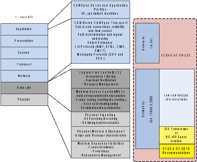 Figure 41: Relationship between ISO layering, ISO 11898, CiA 301 and ECSS CAN standard definitions
CANbus network
The Controller Area Network (CAN) is a serial communications protocol which efficiently supports distributed real-time control with a very high level of security.
For a detailed and authoritative introduction to the CAN features and characteristics refer to:
Texas Instrument’s - Application Report SLOA101A – August 2002 – Revised July 2008 - Introduction to the Controller Area Network (CAN) by Steve Corrigan [4]
Extensive literature on use of CAN for high reliability command and control exists. Some of the most interesting articles are reported in the bibliography of this standard (see [9],[17],[18],[19],[20],[33],[34],[35],[36]).
Physical layer
Clause 5 lists the requirements related to the physical layer.
Communication model
The communication model is based on a CAN Network master connected to up to 126 slave nodes (the number of possible nodes depends on the physical layer capabilities).
The network is organized in a strict master/slave relationship (see Figure 42).
 Figure 42: Example of minimal implementation topology
The CAN physical layer comprises the electrical, mechanical and performance characteristics of the cabling, connectors, termination resistors, CAN transceivers, and optional optical couplers.
The approach of this document is to make reference to ISO 11898-1:2003 and ISO 11898-2:2003 wherever possible; detailing only the specific restrictions where appropriate to satisfy the requirements for spacecraft applications.
For convenience, the Data Link layer description is included in this document within the physical layer clause. The Data Link conforms to ISO 11898-1:2003, which is based on the Bosch CAN 2.0B (1991) specification, [3].
CANopen higher layer protocol
The ISO 11898 standard specifies the CAN Network physical and data link layers. ISO 11898 provides fast, prioritized, reliable, broadcast message transmission with sophisticated error detection and error handling and can fulfil all requirements of small closed networks. However, it is not adapted to large, extendable, interconnected networks from different manufacturers
For this purpose this standard recommends the use of CANopen as a higher layer communication protocol operating over the CAN Network.
CANopen is a standard widely used in automation and industrial applications, including safety critical and maritime applications implementing redundant communication busses.
One of the strengths of CANopen is the simplicity of the redundancy management implementation. In addition, CANopen allows simple standardization of Electronic Data Sheets (EDS) making interoperability far more straightforward.
The description of a device's communication functionality and objects and its device-specific objects is provided in the form of an EDS), an ASCII or XML file with a strictly defined syntax. A description of the object configuration of an individual device with its default parameter values, as well as maximum and minimum ranges is called a Device Configuration File (DCF) and has the same structure as an EDS (see [28], [29], [30] for reference). Both file types are defined in the CANopen specification.
The CAN ISO 11898 standard defines only the layers 1 and 2; in practice these are completely handled by the CAN hardware, significantly reducing the implementation effort for node developers. However, a high level protocol is necessary in order to define how the CAN message frame's 11-bit identifier and 8 data bytes are used. Building CAN-based space systems guaranteeing interoperability and interchangeability of devices of different manufacturers requires a standardized application layer and 'profiles', standardizing the communication system, the device functionality and the system administration:
The application layer provides a set of services and protocols useful to every device on the network imaginable.
The communication profile provides the means to configure devices and communication data and defines how data is communicated between devices.
Device profiles (not foreseen in the present standard) may add device-specific behaviour for (classes of) devices (e.g. digital I/O, analogue I/O, motion controllers, encoders).
The CANopen communication model defines four types of messages (communication objects):
|
1
|
Administrative messages (Layer management, network management and identifier distribution services):
|
|
2
|
Service Data Object (SDO):
|
|
3
|
Process Data Object (PDO):
|
|
4
|
Predefined messages or Special Function Objects:
|
Clause 6 specifies requirements applicable to application layer protocol.
Reference is made to the CiA Standard 301 Version 4.2.0 (CANopen). Note that this standard also specifies additional details or constraints in addition to those specified by CANopen.
Time distribution
Overview
This standard defines a time distribution protocol based on the use of CANopen PDOs. The protocol may be used over a CAN Network and in conjunction with CANopen. The time distribution service defined as part of the CANopen is considered inadequate for spacecraft requirements.
The time distribution and synchronization protocols specified in this standard distribute a sample of the central time to devices maintaining a local time.
The time distribution protocol provides a mechanism to transfer and read back the time with no specific requirements on accuracy. The optional high-resolution time distribution protocol allows for the best possible time synchronization via the CAN Network. It is possible to use both protocols on the same CAN Network.
This standard makes no assumptions on the relationship or maximum time error between the central time and the local time. In particular, the frequency of local time updating and any associated mechanisms for adjusting the local time without loss or duplication of time codes are device and application specific and outside the scope of this standard.
The time distribution protocol is based on a single PDO transmission from the Time producer to one or more Time consumers. Read-back of the local time is facilitated by means of dedicated PDOs. There are no specific features in this protocol to control the accuracy of the time distribution.
The High-resolution time protocol uses the SYNC object to achieve the highest possible synchronization accuracy when distributing time over the CAN Network. Read-back of the local times is facilitated by means of dedicated PDOs. The actual accuracy of the time distribution is implementation dependent. Accuracy in the microsecond range can be achieved with a bit rate of 1 Mbps.
SYNC message and protocol
Synchronous network behaviour in CANopen networks can be achieved with the SYNC protocol. The cyclically transmitted SYNC message indicates to the consumers to start their application-specific behaviour, which is coupled to the reception of the SYNC message. Synchronous PDOs use the SYNC message as a triggering event for PDO transmission and as indication for sending the data valid, which has been received previously to the SYNC message.
The SYNC Message format is defined in CANopen CiA 301 V4.2.0 section 7.3.5.
The SYNC protocol uses a producer/consumer communication coherence. There is one SYNC producer and several SYNC consumers. In case a device supports the SYNC consumer capability, this functionality can be switched on in the COB-ID entry for the SYNC object (1005h). This entry also provides the CAN-Identifier for the SYNC message. All consumers need to assign the same CAN-Identifier to that COB-ID entry. Furthermore, they indicate the consumer functionality in bit 30.
Bit timing
Even if minor errors in the configuration of the CAN bit timing do not result in immediate failure, the performance of a CAN network can be reduced significantly. In most of the cases, the CAN bit synchronization amends a faulty configuration of the CAN bit timing so that only an occasional error frame is generated.
In the case of arbitration however, when two or more CAN nodes simultaneously try to transmit a frame, a misplaced sample point may cause one of the transmitters to become Error Passive.
The analysis of such sporadic errors requires a detailed knowledge of the CAN bit synchronization inside a CAN node and of the CAN nodes’ interaction on the CAN Network.
Further information about bit timing parameters are available in [11], [12], [21], [22], [23], [24].
Redundancy management and monitoring
Overview
Spacecraft on-board communication busses are typically implemented using a redundant physical media topology that is resilient to single point failure in cabling or connector faults.
Neither the CAN Network specification ISO 11898 nor the CANopen standard define redundancy management. However, both specifications define capabilities that are suitable for use when implementing a highly reliable bus system.
A redundant communication system requires redundant communication channels and also a redundancy management scheme. Components that can be redundant are the physical connection, the bus transceiver and the bus controller.
This standard specifies two alternative architectures for the implementation of the bus interfaces in the CAN nodes. The selective bus access architecture allows communication on one bus at a time, whereas the parallel bus access architecture allows simultaneous communication on both a nominal and a redundant bus. Both architectures can be used simultaneously in the same system
A redundancy management scheme for a cold redundant bus system is specified and consistent with the defined bus interface architectures.
Redundancy management for hot/warm redundant bus systems as well as node level redundancy management are application specific and therefore outside of the scope of this document. The redundancy management scheme defined in this standard uses the CANopen Heartbeat object as a means to monitor and control the bus system.
The redundancy management is specified in clause 8. This clause specifies the implementation and protocol requirements related to redundancy management at bus level. The redundancy management scheme is based on the assumption that there is always one dedicated node responsible for the bus redundancy management.
This standard specifies two alternative methods for the implementation of the CAN node transceivers: see clause 5.3.1a.
Node Monitoring via Node-Guarding or Heartbeat Messages
To ensure operability of network nodes, CANopen provides two alternatives:
Cyclic querying of the node state by a higher order instance, the so-called "NMT-Master" ("node guarding" principle) or
Automatic transmission of a "heartbeat message" by the network nodes ("heartbeat" principle).
With node guarding, a certain network node (the so-called NMT-master) requests the other nodes in the network (referred to as NMT-slaves) with a CAN remote frame one after the other at defined intervals ("guard time") to transmit a datagram with its current communication state (stopped, operational, pre-operational) together with a toggle-bit. If a node does not respond to the request of the NMT-master within a certain time ("node life time"), this is assessed as a failure of the node and indicated to the host controller of the NMT-master as a "node-guarding event". On the other hand, the NMT-slaves also monitor whether they have received a request from the NMT-master within their "life time". If such a request was absent for longer than the "life time" of a node, the NMT-slave assumes that the NMT-master itself has failed and indicates this event as "Life guarding event" to its host controller.
With node guarding, one CAN identifier per node is used to request the communication state. Low priority messages identifiers with a value of 1792 + NODE-ID are reserved for this.
With node monitoring according to the heartbeat principle, a node automatically transmits its communication state (with format as in Figure 43) at regular intervals as evidence of its communication ability. The interval between two heartbeat messages ("heartbeat interval") of a heartbeat producer is configured via the object directory entry [1017]. A value of 0 disables the heartbeat mechanism. The so-called "heartbeat consumer time" of the up to 127 network nodes is given in the OD entry [1016]. This time interval describes the maximum time within which the arrival of a heartbeat message is expected by a particular node.
 Figure 43: Format of hearthbeat message
In a guarding or heartbeat message the communication status is transmitted in the form of a one-byte value.
The following state values are defined:
0x00 - Bootup;
0x04 - Stopped;
0x05 - Operational;
0x7F - Pre-Operational.
The highest value bit is assigned a special role - with guarding it toggles, with heartbeat it is constant 0.
Bus monitoring and reconfiguration management
The bus monitoring and reconfiguration management protocol defined in this standard make use of CANopen NMT objects (and in particular the CANopen Heartbeat message) to determine the active bus.
The Redundancy Master defines the bus to be considered active by periodic transmission of CANopen Heartbeat messages on the active bus. The slave nodes monitor the presence of the Heartbeat message from the master to determine the active bus.
In addition to the Master Heartbeat messages the slave nodes also detects if another CANopen NMT message is received from the master. If so, the bus on which the NMT message was received is considered the active one. Further information is given in Annex A.
Connectors and pin assignments
Clause 10 specifies the connector types and pin allocations to be used for connecting the CAN Network to the CAN nodes.
Minimal protocol set
In order to cater for applications with extremely simplistic needs, which cannot embed a high amount of computing power and do not have in-flight reconfiguration needs, a minimal protocol set is specified in clause 9.
This protocol is based on a restriction of the “pre-defined master/slave connection set” proposed by the CANopen.
With this minimal implementation, the CANopen object dictionary exists but objects are not necessarily defined as entries of a device and are not necessarily accessed with their index. Indexes, sub-indexes, data types, parameters, mapping parameters can be too complex and too bulky to manage relative to the available computing resources. It is therefore acceptable that the CANopen objects and their mapping are hard-coded.
To reduce the hardware and software required by devices, slave nodes may work autonomously with minimum intervention of the master, and without the need of Network Management (NMT).
The COB-ID assignment complies with the clause 6.10 of this standard.
Physical layer
Topology
Physical topology
General
A spacecraft system using a CAN Network shall use either of the following physical topologies:
- A Linear multi-drop topology as depicted in Figure 51.
- A Daisy chain topology as depicted in Figure 52.
For connector implementation see clause 10, all implementations are possible, if the pin-out for the main and redundant bus is maintained.
 Figure 51: Linear multi-drop topology
For CAN Network devices connected in a daisy chain configuration, the connection between two subsequent trunks of the CAN Network shall be performed inside the connector as shown in Figure 52.
With this configuration the two topology options can be employed exclusively or in combination.
 Figure 52: Daisy chain topology.
Equal cable lengths between devices shall be avoided.
Equal cable lengths for Drop (stub) cable shall be avoided.
The reason to avoid equal cable lengths between devices is to minimize standing waves. Similar reasons apply to drop (stub) cable lengths.
Terminators
Bus terminators shall be implemented according to ISO 11898-2:2003 clause 7.5.2.
Terminating resistors shall not be incorporated inside NMT slave equipment.
See Figure A-2 and Figure A-3 for examples.
For system configuration with all communications driven by a master/slave concept the terminating resistors may be incorporated inside the Master at the end of the bus.
Terminating resistors may be incorporated inside the CAN Network cable.
The terminator resistor(s) shall be installed at each end of the bus segment as shown in Figure 51 and Figure 52.
A 120 ohm terminating resistance shall be installed at each end of each bus segment.
Terminating resistors can consist of two 60 ohm resistors as shown in Figure A-5 (Split Termination).
Maximum bus length and drop length
The maximum bus length shall be implemented in accordance with ISO 11898-2:2003 clause 7.5.
The maximum stub drop lengths shall be implemented in accordance with ISO 11898-2:2003 clause 7.5.3.
Since stub-lines are un-terminated, signal reflections can develop in a stub that drives signal levels back and forth across a receiver's input thresholds, creating errors. Bit-sampling occurs near the end of a bit, so it is mandatory that all signal reflections in a CAN stub-line are attenuated before or during the propagation delay segment to provide an adequate margin of safety (see [5],[7],[8],[12] for detailed discussion).
To minimize reflections, stub-line length shall not exceed one-third (1/3) of the network critical length.
- 1 See definition 3.2.16.
- 2 Additional considerations and requirements are addressed in 5.4.3.
Number of network devices
The CAN physical layer interface of each node shall be designed such that it can be incorporated in a system with at least 64 network nodes.
The RS-485 physical layer interface of each node shall be designed to be incorporated into system with a maximum of 32 nodes.
- 1 The maximum number of network devices in a system is a function of the electrical properties of the devices and circuits of the CAN transceivers. Requirements for the CAN transceivers are specified in clause 5.3.
- 2 The maximum number of nodes main limit is the driving capability of a CAN transmitter. It’s usually specified in data sheets by the minimum allowed load resistance. The load of a transmitter in the CAN Network is composed of the termination resistors and the parallel combination of differential input resistances of all nodes.
- 3 The RS-485 implementation described in 5.3.5 cannot support more than 32 standard RS-485 Unit Load devices as described in [5].
Medium
Cable requirements
CAN primary bus
Each CAN node shall implement the provision to interface to at least one CAN Network in accordance with the physical medium specification of ISO 11898-2:2003 Table 9.
CAN redundant bus
If implemented, the second (redundant) CAN Network shall also be designed in accordance with the physical medium specification of ISO11898-2:2003 Table 9.
Redundancy management is addressed in clause 8.
CAN Network cable
The CAN Network cable shall be compliant with ISO 11898-2:2003, clause 7.5.
The application specific CAN Network cable selection is left to the system engineer. Guidelines can be found in [11],[13] [26].
Shield – system specific
All data cables shall use shielded twisted-pair cables.
Cable shielding shall comply with ECSS-E-ST-20-07 clause 4.2.13
A short pig-tail shall be crimped to the shield end at each connector end and then attached to connectors backshells and box chassis.
If individual shielding of the signal pairs is used, the same terminating technique as for the overall shield shall be used.
As described in ECSS-E-ST-20-07 4.2.13.2f network cabling should lie as close as possible to satellite structure and have intermediate overshield bonding points to minimize EMI pick up. This prevents parasitic currents from flowing in the shield between ground connections.
Connectors
Connector type
If connectors are selected from the ones described in clause 10, they shall comply with their associated requirements.
If connectors are not selected from the ones described in clause 10, then they shall comply with the naming convention defined in clause 10.2.
It is not practical to define a connector to suit all applications, systems and equipment. In particular, when several functions are grouped on a single connector for density reasons. Clause 10 specifies connectors for CAN Network standalone connections. Device-on-bus compatibility is maintained by implementing the configuration and signal pin-out for that connector.
Receptacles (Sockets)
Receptacles shall be used on board and unit assemblies.
Receptacles shall be equipped with male contacts.
Plugs
Plugs shall be used on cable assemblies.
Plugs shall be equipped with female contacts.
The conductors shall be directly soldered or crimped to the contacts.
Reserved pins
Pins designated as ‘Reserved’ in clause 10 of this standard shall not be used.
Reserved Pins are reserved for functions in future updates to this standard.
Transceiver characteristics
General
The physical layer specifications shall comply with either ISO11898-2:2003 as specified in 5.3.2 or EIA RS485 as specified in 5.3.5.
ISO11898-2:2003 should be used for transceiver electrical level compliance.
ISO 11898-2:2003 transceiver electrical characteristics
Transceivers shall comply with the physical medium attachment sub-layer specification of ISO 11898-2:2003 clause 7.2.
An excerpt of ISO 11898-2:2003 specification is illustrated in Table 51.
Table 51: CAN levels in ISO 11898-2:2003
|
Signal
|
Recessive
|
Dominant
| ||||
|
Min
|
Nom
|
Max
|
Min
|
Nom
|
Max
| |
|
CAN_High (V)
|
2,00
|
2,50
|
3,00
|
2,75
|
3,50
|
4,50
|
|
CAN_Low (V)
|
2,00
|
2,50
|
3,00
|
0,50
|
1,50
|
2,25
|
|
H-L (V)
|
-0,50
|
0,00
|
0,05
|
1,50
|
2,00
|
3,00
|
Resistance to electrical CAN Network faults
General
Transceivers shall withstand a voltage in the range between -10V and +15V on their bus pins w.r.t to chassis ground.
- 1 This requirement introduces a dedicated specification for ‘battery voltage’ as defined in ISO 11898-2:2003 that is relative to use of CAN in space equipment.
- 2 The rationale behind this choice is that those numbers envelope possible performances from present and future ISO and RS-485 transceivers (see for example absolute maximum ratings in [37]).
A robust system to manage babbling idiot nodes shall be present. - 1 Although unlikely, the theoretical presence of babbling idiots contending the bus cannot be ruled out. It is the System designer's duty to consider several possible ways to cope with this failure occurrence, including independent unit RESET/Power removal or low level CAN message for transceiver inhibit/reset.
- 2 This requirement does not impose an explicit independent reset/off signal per unit.
Unpowered nodes shall not disturb the bus.
This can be achieved by, for example, correct bus sizing, choice of bit timing, evaluation of added capacitance from OFF terminals (connector, transceiver, PCB).
Bus failure detection requirements
Overview
Clause 5.3.3.2.2 and 5.3.3.2.3 replace the requirements of ISO 11898-2:2003 clause 7.6 "Bus failure management".
Figure 19 of ISO 11898-2:2003 is a graphical representation of the failure modes (case 1 to case 9) covered in clause 5.3.3.2.3.
Table 52 is a summary of the requirements from clauses 5.3.3.2.2 and 5.3.3.2.3.
Disconnection, power off, loss of ground or shielding
If one node becomes disconnected from the bus, the remaining nodes shall continue communicating.
As an example for cold redundant units connected to the bus when the active one gets disconnected.
If one node loses power, the remaining nodes shall continue communicating.
As an example for cold redundant units connected to the bus.
If one node loses ground, the remaining nodes should continue communicating.
Ability for faulty bus to keep communicating depends on bus topology, data rate and physical implementation.
In case of loss of the shield connection at any node, all nodes should continue communicating.
- 1 This failure can happen only if a shielded cable is used. It can lead to common mode voltage induced between the shield and the two signal wires.
- 2 Ability for faulty bus to keep communicating depends on bus topology, data rate and physical implementation.
Open and short failures
If CAN_H or CAN_L are interrupted, the remaining nodes shall continue communicating with reduced signal-to-noise ratio.
Ability for faulty bus to keep communicating depends on bus topology, data rate and physical implementation.
If CAN_H or CAN_L are interrupted, the disconnected node may continue communicating.
If CAN_H shorted to Vfault <= +7V, the CAN bus should continue communicating with reduced signal-to-noise ratio.
- 1 Ability for faulty bus to keep communicating depends on bus topology, data rate and physical implementation.
- 2 Single event effect (SEE) resilience of the part is typically not guaranteed.
If CAN_H shorted to Vfault in the range as defined in 5.3.3a, upon fault removal the CAN network shall resume communication with no ill effects to CAN nodes.
If CAN_H is shorted to Vfault the CAN network cannot communicate.
In case a redundant bus is available, it should be possible to switch to the redundant CAN network if CAN_H is shorted to Vfault outside the range as defined in 5.3.3a.
This can cause irreversible fault to the transceivers.
If CAN_L is shorted to ground all nodes should continue communicating.
Ability for faulty bus to keep communicating depends on bus topology, data rate and physical implementation.
If CAN_H shorted to ground, upon fault removal the CAN network shall resume communication with no ill effects to CAN nodes.
If CAN_H is shorted to ground the CAN network cannot communicate.
If CAN_L is shorted to Vfault in the range as defined in 5.3.3a, upon fault removal the CAN network shall resume communication with no ill effects to CAN nodes.
- 1 If CAN_L is shorted to Vfault the CAN network cannot communicate.
- 2 Ability for faulty bus to keep communicating depends on bus topology, data rate and physical implementation.
- 3 Single event effect (SEE) resilience of the part is typically not guaranteed.
In case a redundant bus is available, it should be possible to switch to the redundant CAN network if CAN_L is shorted to Vfault outside the range as defined in 5.3.3a.
This can cause irreversible fault to the transceivers.
If CAN_L is shorted to CAN_H, upon fault removal the CAN network shall resume communication with no ill effects to CAN nodes.
If CAN_H and CAN_L wires are interrupted at the same location, CAN nodes upstream the break shall:
- remain communicating with reduced signal-to-noise ratio, and
- upon fault removal resume communication with no ill effects to CAN nodes. In case of loss of one connection to termination network all nodes shall continue communicating.
Ability for faulty bus to keep communicating depends on bus topology, data rate and physical implementation.
Table 52 – CAN failure modes and recommended FDIR actions.
|
Description of Bus Failure
|
Corresponding Network behaviour
|
Quality of specification
|
Comment
|
|
One node becomes disconnected from the bus
|
The remaining nodes continue communicating.
|
Mandatory
|
In a bus configuration where cold redundant units are connected to the same bus, any unit disconnection do not disturb the bus.
|
|
One node loses power
|
The remaining nodes continue communicating.
|
Mandatory
|
In a bus configuration where cold redundant units are connected to the same bus, any power loss does not disturb the bus.
|
|
One node loses ground
|
The remaining nodes continue communicating.
|
Recommended
|
Ability for faulty bus to keep communicating depends on bus topology, data rate and physical implementation.
|
|
Loss of the shield connection at any node
|
All nodes continue communicating.
|
Recommended
|
This failure can happen only if a shielded cable is used. In this case the loss of shield connection at one node can cause common mode voltage induced between the shield and the two signal wires.
Ability for faulty bus to keep communicating depends on bus topology, data rate and physical implementation. |
|
Open and short failures (The numbers 1 to 9 refer to Cases 1 to 9 in Figure 19 in ISO 11898-2:2003)
|
|||
|
1 CAN_H interrupted
|
The remaining nodes continue communicating with reduced signal-to-noise ratio.
Disconnected node continue communicating |
Mandatory Recommended |
Ability for faulty bus to keep communicating depends on bus topology, data rate and physical implementation.
|
|
2 CAN_L interrupted
|
The remaining nodes continue communicating with reduced signal-to-noise ratio.
Disconnected node continue communicating |
Mandatory Recommended |
Ability for faulty bus to keep communicating depends on bus topology, data rate and physical implementation.
|
|
3a CAN_H shorted to Vfault <= +7V
|
CAN bus continues communicating with reduced signal-to-noise ratio.
|
Recommended
|
Ability for faulty bus to keep communicating depends on bus topology, data rate, physical implementation.
Single event effect (SEE) resilience of the part is typically not be guaranteed. |
|
3b CAN_H shorted to Vfault in the range as defined in 5.3.3a
|
CAN network cannot communicate.
Upon fault removal CAN network resumes communication with no ill effects to CAN nodes. |
Acceptable.
Mandatory |
This assumes that the network is made with redundant buses, and each node is connected to both buses.
|
|
3c CAN_H shorted to Vfault outside the range defined in 5.3.3a
|
CAN network cannot communicate.
|
Acceptable.
|
This can cause irreversible fault to the transceivers.
Fault isolation through switch to redundant CAN network is still possible. |
|
4 CAN_L shorted to ground
|
All nodes continue communicating.
|
Recommended
|
Ability for faulty bus to keep communicating depends on bus topology, data rate, physical implementation.
|
|
5 CAN_H shorted to ground
|
CAN network cannot communicate.
Upon fault removal CAN network resumes communication with no ill effects to CAN nodes. |
Acceptable.
Mandatory |
This assumes that the network is made with redundant buses, and each node is connected to both buses.
|
|
6a CAN_L shorted to Vfault <= as defined in 5.3.3a
|
CAN network cannot communicate.
Upon fault removal CAN network resumes communication with no ill effects to CAN nodes. |
Acceptable.
Mandatory |
Ability for faulty bus to keep communicating depends on bus topology, data rate and physical implementation.
Single event effect (SEE) resilience of the part is not guaranteed. |
|
6b/6c CAN_L shorted to Vfault outside the range as defined in 5.3.3a
|
CAN network cannot not communicate.
|
Acceptable.
|
This can cause irreversible fault to the transceiver.
Fault isolation through switch to redundant CAN network is still possible. |
|
7 CAN_L shorted to CAN_H
|
CAN network cannot communicate.
Upon fault removal CAN network resumes communication with no ill effects to CAN nodes. |
Acceptable.
Mandatory |
|
|
8 CAN_H and CAN_L wires interrupted at the same location
|
CAN nodes upstream the break remain communicating with reduced signal-to-noise ratio
Upon fault removal CAN network resumes communication with no ill effects to CAN nodes. |
Mandatory
Mandatory |
|
|
9 Loss of one connection to termination network
|
All nodes continue communicating.
|
Mandatory
|
Ability for faulty bus to keep communicating depends on bus topology, data rate and physical implementation.
|
Transceiver isolation
Equipment implementing an isolated bus interface shall comply with the requirements of this standard, which uses an isolated Transceiver rather than isolated CAN signals.
Both the CAN Network signal lines and transceiver power supplies shall be isolated.
Electric ground support equipment (EGSE) designs for CAN bus shall use transceiver isolation as specified by this standard.
- 1 Isolators impose an additional propagation delay that can restrict the maximum possible bus length. It is the designer's duty to take into account that the maximum round trip interface delay time for a device is still compliant with the bit timing requirements of clause 5.4.
- 2 The isolation scheme proposed in this standard ensures that it is possible to connect both isolated and non-isolated nodes to the same network.
Physical layer implementation based on RS-485 transceivers
ISO11898-2:2003 and RS-485 devices shall never be used on the same bus.
Detailed implementation for RS-485 transceiver
Data Input (DI) and Drive Enable (DE) of the RS-485 transceiver shall be driven by the inverted CAN Transmit bit of the controller (TXD).
See Figure A-2 and Figure A-3 for examples.
A fail-safe mechanism shall be implemented to avoid that a faulty controller forces the bus into permanent dominant level and harms correct network operation.
An example of a fail-safe mechanism is an input filter. More details can be found in [6], [14] and [15].
Receive Enable (RE) pin shall be always active (enabled).
Receive Output (RO) shall be taken as the true value of the CAN signal.
Bit timing
Bit rate 1 Mbps
All transceivers shall support the 1 Mbps high-speed CAN bit rate.
ISO 11898-2:2003 specifies high-speed CAN as 125 kbps to 1 Mbps.
Other bit rates
If a device supports more bit rates than specified in requirement 5.4.1a it shall support one or more of the following rates:
- 500 kbps
- 250 kbps
- 125 kbps A device may implement additional bit rates only after complying to all the rates stated in 5.4.2a.
Bit timing
A CAN controller shall support configurable Time Quanta and Sample Point.
Bit timings and Sample Point used in systems compliant to this standard shall be calculated using the method explained in iCC 2012 CAN.
For each CAN system the option which allows the most propagation delay while still satisfying the oscillator tolerance requirement shall be chosen.
Resynchronization Jump Width (RJW), also referred to as Synchronization Jump Width (SJW) in some controllers, shall be configurable between 1 to MIN(4, Phase_Seg1) Time Quanta.
This parameter is used as a maximum limit of bit time adjustment in the case of re-synchronization when there is an edge phase error detected by the receiver CAN nodes.
Synchronisation shall be performed on ‘recessive to dominant’ edges only.
This standard does not define a limit for each device’s CAN interface round trip propagation time since the correct definition, at system level, of Bit timings Sample Point as per clause 5.4.3 ensures bus robustness.
Electromagnetic compatibility (EMC)
The CAN Network system shall comply with EMC requirements as defined in ECSS-E-ST-20 clause 6.
Data link layer
ISO 11898 compliance
The CAN Data Link layer shall comply with ISO 11898-1:2003.
- 1 The ISO 11898-1:2003 document inherits data link layer definitions from the Bosch specification, [3].
- 2 This implies also that both 11-bit and 29-bit identifiers can be used on the CAN Network.
Fault confinement
The Data Link layer shall implement fault confinement, as specified in ISO 11898-2:2003 clause 7.6, Fault Confinement.
- 1 The ISO 11898-2:2003 document inherits fault confinement definitions from the Bosch specification, [3]. It is left to the system engineer as how best to utilize the fault containment mechanisms provided for in clause 7.6 of the ISO reference for system FDIR purposes.
- 2 The ISO 11898-1:2003, specifies that only Bus Off and Normal Mode indications to be provided to the application.
The indication of Error Active and Error Passive should be provided to the application.
Non-intrusive read access at application SW level to the error counters shall be provided to allow assessment of the quality of the bus.
CANopen higher layer protocol
Service data objects
If Service data objects (SDOs) are implemented, the SDO shall be as specified in CANopen.
The implementation of Service Data Objects (SDO) is optional. This is used primarily to access to the device Object Dictionary. In systems only requiring configuration on ground, the Client SDO can be implemented in a PC or similar. SDOs can be used for configuration of the CAN nodes in-flight. This choice is left to the particular application and out of scope for this standard.
Process data objects
Process data objects (PDOs) shall be implemented according to the CANopen specification.
CANopen restricts the number of different PDOs to 512 Transmit PDOs and 512 Receive PDOs per node. A device can implement an arbitrary number of PDOs up to the limit defined by the CANopen standard.
Synchronisation object
All devices requiring synchronous communication shall implement a SYNC object.
A device can be a SYNC producer or SYNC consumer depending on its functionality.
The SYNC object shall be implemented according to CANopen CiA 301 V4.2.0 section 7.2.5.
Emergency object
If implemented, the Emergency object shall:
- be used only for Error reporting,
- have error codes as defined in CANopen standard. All CANopen defined Error codes shall be implemented.
The implementation of the Emergency object is optional.
Network management objects
Module control services
All devices, excluding the minimum configuration specified in clause 9.3, shall implement the following CANopen NMT Module Control Services:
- Start Remote Node
- Stop Remote Node
- Enter Pre-Operational
- Reset Node
- Reset Communication
Error control services
All devices shall implement the Heartbeat service as specified in CANopen CiA 301 V4.2.0 section 7.2.8.3.2.2.
All slave nodes shall consume the redundancy master Heartbeat message.
CANopen specifies that it is mandatory to implement either the Node/Life Guarding or the Heartbeat services and protocols. This standard is more restrictive and specifies only the Heartbeat service and protocol as mandatory.
Bootup service
All devices shall implement the minimum Bootup service as specified in CANopen CiA 301 V4.2.0 section 7.2.8.2.3.
Node state diagram
All devices shall implement the NMT state diagram as specified in CANopen CiA 301 V4.2.0 section 7.3.2.
Electronic data sheets
Each device in the network shall be accompanied by a Device Configuration File in accordance with the CANopen standard as per CiA DS306 Version 1.3.0.
The functions and properties of CANopen devices are largely described by objects and are managed in an object directory. The object directory is represented in electronic form by so-called EDS files. EDS files are a fixed component of standardization in the CANopen field (CiA DS306) and play a key role in configuring CANopen networks. The file format specified by CiA guarantees that device descriptions generated by tools of different software producers can be read and processed. All participants in the development of CANopen systems benefit from complete and correct EDS files for the CANopen devices available on the market.
Device and application profiles
The device profile designer shall coordinate the allocation and definition of the device profile with CAN in Automation (CiA) for inclusion in their database.
- 1 This is in order to ensure that any device profile defined within the space community is compatible with the CANopen device profile requirements.
- 2 In general, standardized profiles simplify system integration by means of off-the-shelf configuration tools. Devices compliant to the same profile are interoperable and partly or completely exchangeable.
- 3 The procedure for definition of a new Device Profile is established by CiA via definition of a Draft Standard proposal (DSP).
Each device implementing a built-in self-test functionality shall provide the means to start the test using an object in the device Object Dictionary.
The result of the test shall be accessible in a dedicated object.
Object dictionary
All devices shall implement an Object Dictionary (OD) according to CANopen.
- 1 Data Types implemented within the OD are application dependent and are built on basic data types.
- 2 For simple systems not using SDO, the object dictionary can be hardcoded.
Synchronous communications
Synchronous data transfers shall be performed using synchronous PDOs as defined in CANopen.
Synchronous PDOs transfer shall be synchronized by receipt of SYNC object as defined in 6.3.
The SYNC producer shall be capable of sending the SYNC object according to CANopen.
Only one device within the network shall act as SYNC producer by issuing periodically the SYNC object.
Bus redundancy management uses SYNC object exchange as described in 8.3.
SYNC consumers implementing the SYNC capability shall react on SYNC object’s reception according to CANopen.
COB-ID and NODE-ID assignment
All devices shall provide the capability of COB-ID assignment as specified by CANopen.
COB-IDs restricted for a specific purpose in CANopen shall not be used other than for that particular purpose.
The capability shall be provided to change any non-restricted COB-ID of a device at any time up to the completion of system level testing without need for a re-qualification of the device.
This implies that COB-ID reassignment capability can be implemented by using SDOs but also by other means such as PROM boxes, straps in connectors, S/W updates or similar can be considered if acceptable for the particular application.
No single point failure shall cause a terminal to validate a false COB-ID.
This implies a protection mechanism on COB-ID assignment.
The NODE-ID shall be hard-coded inside the node.
The Node shall not communicate until a valid NODE-ID has been activated.
The Node–ID shall be configurable when the node is in a specific maintenance mode only.
Each node connected on the CAN Network shall have at least one unique NODE-ID.
The NODE-ID shall be agreed by the customer and the supplier.
The capability shall be provided to change any NODE-ID of a node at any time up to completion of system level test without the need of a re-qualification of the node.
Node‐ID reassignment capability can be implemented by using internal configuration, but also by other means such as PROM boxes, straps in connectors. S/W updates or similar can be considered if acceptable for the particular application.
No single point failure shall cause a terminal to validate a false NODE-ID.
This implies that a protection mechanism on NODE-ID assignment is used.
Each hot redundant node connected to the same physical CAN Network shall use different COB-IDs.
In the case where two or more redundant nodes are connected and operating on the same physical CAN Network, the communication objects of each redundant node shall be uniquely identifiable.
For each device, the default COB-ID allocation to be implemented before delivery of the device shall be agreed between the customer and the supplier.
The COB-ID assignment upon device delivery is thus not restricted to the CANopen pre-defined connection set.
Time distribution
Time objects
Time code formats
Each device on the CAN network that maintains time information shall use Spacecraft Elapsed Time (SCET) as defined in clause 3.2 of CCSDS 301.0-B-4.
The time code format of the SCET is the CCSDS UNSEGMENTED TIME CODE (CUC) an unsegmented binary count of seconds and binary powers of sub-seconds. The SCET is thus a free running counter with a MSB of up to 232 seconds and LSB sub-second representations down to 2-8, 2-16 or 2-24.
Each device on the CAN network that maintains time information may use Spacecraft Universal Time Coordinated (UTC) as defined in ECSS-E-70-41 Annex C.
If the spacecraft provides the optional service of maintaining the UTC on board, the format of the UTC shall be that of the CCSDS Day Segmented time code (CDS).
The CDS is a 16 or 24 bit binary representation of number of days elapsed from a predefined epoch, 32 bits represent the number of ms and an optional 16 or 32 bit field represents the sub-milliseconds.
This standard allows for either of the time code formats to be used as long as all devices in the network support the selected time code format. There are however, some limitations in terms of resolution and size of the fields.
Network Devices shall use either the Spacecraft elapsed time object or the Spacecraft universal time coordinated (UTC) object.
Spacecraft elapsed time objects
The Spacecraft elapsed time objects (SCET) shall be implemented in all devices that maintain time information.
Each device shall implement one Local SCET Set and one Local SCET Get object in the device Object Dictionary.
The Local SCET Set object shall allow setting the local time of the node via the CAN Network.
The Local SCET Get object shall allow reading the local time of the node via the CAN Network.
The Local SCET Set and Local SCET Get objects shall be of a compound data type according to the following SCET definition:
struct { unsigned 32 Coarse Time unsigned 24 Fine Time (sub seconds) } SCET The Local SCET Set and Local SCET Get objects shall be mapped into the CAN frame according to Figure 71.
It is up to the designer to decide the implemented size of the Fine Time counter in a particular device.
 Figure 71: Format for objects containing the SCET
If a device supports less than 24 bits of fine time, the unused least significant bits shall be set to zeroes whenever the SCET is transmitted from a device.
If a device supports less than 24 bits of fine time, the unused least significant bits shall be interpreted as don’t-care whenever a device receives the SCET.
Spacecraft universal time coordinated objects
Each device supporting UTC shall implement one Local UTC Set and one Local UTC Get object in the device Object Dictionary.
The Local UTC Set object shall provide the capability of setting the local time of the node via the CAN Network.
The Local UTC Get object shall provide the capability of reading the local time of the node via the CAN Network.
The Local UTC Set and Local UTC Get objects shall be of a compound data type according to the following UTC definition:
struct { Unsigned 16 Day Unsigned 32 ms of day Unsigned 16 submilliseconds of ms } UTC The Local UTC Set and Local UTC Get objects shall be mapped into the CAN frame according to Figure 72.
It is up to the designer to decide if the “submilliseconds of ms” field is used in a particular device.
 Figure 72: Format for objects containing the Spacecraft UTC
If a device does not support the “submilliseconds of ms” field, the unused least significant bits shall be set to zeroes whenever the time object is transmitted from a device.
If a device does not support the “submilliseconds of ms” field, the unused least significant bits shall be interpreted as don’t-care whenever a device receives the time object.
Time distribution and synchronization protocols
General
Each device on the network that maintains time information shall be compliant to the Time distribution protocol specified in clause 7.2.2.
Time distribution protocol
The Time Producer shall map the Local SCET Get object (7.1.2) or the Local UTC Get object (7.1.3) to a dedicated Spacecraft Time PDO transmit PDO.
The Time Producer shall use the Spacecraft Time PDO to convey its local time to the time consumers.
The Time Consumers shall map the Local SCET Set or Local UTC Set objects to the Spacecraft Time PDO receive PDO.
There shall be only one Spacecraft Time PDO in a particular system.
Each Time consumer shall map the Local SCET Get object (7.1.2) or the Local UTC Get object (7.1.3) to a dedicated Local Time PDO.
The Time consumers shall use its Local Time PDO to convey its local time on the CAN Network.
There shall be one Local Time PDO for each node maintaining local time.
The various transmission types defined in CANopen allow to use a number of different methods to transmit the Spacecraft Time PDO and Local Time PDOs. However, the details are application specific and out of scope for this standard.
High-resolution time distribution protocol
The Time Producer shall map the Local SCET Get object (7.1.2) or the Local UTC Get object (7.1.3) to a dedicated Spacecraft Time PDO transmit PDO.
The Time Producer shall use the Spacecraft Time PDO to convey its local time to the time consumers.
The value of the Spacecraft Time PDO shall correspond to the spacecraft time when the last preceding SYNC object was successfully transmitted.
The SYNC Producer and the Time Producer shall be implemented as separate entities.
The Time Producer shall implement the Spacecraft Time PDO with a transmission type of 1-240.
Transmission types 1-240 imply that the Time Producer samples its local time on successful receipt of the SYNC object and thereafter send the Spacecraft Time PDO.
The Spacecraft Time PDO defined in 7.2.3a shall be used for conveying the time information.
This prevents the use of Time object as specified in CANopen.
The Time Consumers shall map the Local SCET Set or Local UTC Set objects to the Spacecraft Time PDO receive PDO.
Each Time consumer shall map the Local SCET Get object (7.1.2) or the Local UTC Get object (7.1.3) to a dedicated Local Time PDO transmit PDO.
Each Time consumer shall use its Local Time PDO to convey its local time on the CAN Network.
There shall be one Local Time PDO for each node maintaining local time.
The value of the Local Time PDO shall correspond to the local time when the last preceding SYNC object was successfully received.
- 1 The detailed mechanisms for transmission of the Local Time PDOs are out of scope in this standard.
- 2 It is left to the implementer to define if the sampling of the local time at the occurrence of the SYNC object are implemented in H/W or S/W in order to achieve the required accuracy. It is good practice that generic H/W implementations always provide the possibility to signal, e.g. by means of an interrupt, that the SYNC object has been successfully transmitted/received.
Redundancy management
General
In any system implementing bus redundancy there shall be only one active node at any given time assigned to be the Redundancy Master.
The Redundancy Master shall be identical to the CANopen NMT master.
Node internal bus redundancy architectures
General
The redundancy bus architecture shall be based on only one of the following designs:
- a selective bus access architecture providing communication on only one bus at a time,
- a parallel bus access architecture providing simultaneous communication on both a nominal and a redundant bus.
Parallel bus access architecture
For a parallel bus architecture, the nodes shall implement a Redundancy Master such that each CAN Network is fully and independently accessible via a separate CAN controller.
- 1 See expanded information in A.4.2.
- 2 For bus monitoring protocol see 8.3.3.
- 3 This is to allow the bus Redundancy Master to passively listen for messages on the redundant (not active) bus.
Selective bus access architecture
Nodes implementing the selective bus access architecture shall provide a mechanism allowing the application to select which bus to use.
The details of this selection mechanism is implementation specific and out of scope for this standard.
Bus monitoring and reconfiguration management
Bus redundancy management parameters
Each slave node shall implement the objects listed in Table 81 in its Object Dictionary.
The Master Node shall implement the objects listed in Table 82 in its Object Dictionary.
The objects listed in Table 81and Table 82 shall be programmable by means of SDOs.
This allows variations in CANbus configurations of the object dictionaries as an outcome of failure investigations at data-handling sub-system level.
The objects listed in Table 81 and Table 82 shall be specified by the customer.
- 1 Clause 8.3.1 specifies the parameters that define the characteristics of the reconfiguration protocol.
- 2 Implementations of these objects is not strictly necessary for a minimum configuration as specified in clause 9.3.
Table 81: BUS redundancy management parameters for slaves
|
Parameter
|
Remark
|
|
Consumer Heartbeat Time
|
The Consumer Heartbeat Time parameter is specified by CANopen. The parameter specifies the maximum time allowed between two subsequent Heartbeat messages linked to that heartbeat consumer.
|
|
Producer Heartbeat Time
|
The Producer Heartbeat Time parameter is specified by CANopen. The parameter specifies the maximum time allowed between two subsequent Heartbeat message transmissions.
|
|
Bdefault
|
Bdefault specifies the bus to be considered active after a node power-on, node hardware reset.
|
|
Ttoggle
|
Ttoggle specifies the number of Consumer Heartbeat times during which the node is required to be listening for an NMT HB message on a particular bus before switching to the other bus.
|
|
Ntoggle
|
Ntoggle specifies the number of toggles between the Nominal and Redundant bus in case of no HB message being detected. If an even number is used the last toggle puts the system into Bdefault.
|
|
Ctoggle
|
The counter of Ntoggles (bus toggles) shows the count of the number of toggles that have already been performed by the device.
|
Table 82: BUS redundancy management parameters for master
|
Parameter
|
Remark
|
|
Consumer Heartbeat Time
|
The Consumer Heartbeat Time parameter is specified by CANopen. The parameter specifies the maximum time allowed between two subsequent Heartbeat messages linked to that heartbeat consumer.
|
|
Producer Heartbeat Time
|
The Producer Heartbeat Time parameter is specified by CANopen. The parameter specifies the maximum time allowed between two subsequent Heartbeat message transmissions.
|
|
Bdefault
|
Bdefault specifies the bus to be considered active after a master power-on or master hardware reset.
|
|
Ttoggle
|
Ttoggle specifies the number of Consumer Heartbeat times during which the node is required to be listening for an NMT HB message on a particular bus before switching to the other bus.
|
|
Ntoggle
|
Ntoggle specifies the number of toggles between the Nominal and Redundant bus in case of no HB message being detected. If an even number is used the last toggle puts the system into Bdefault.
|
|
Ctoggle
|
The counter of Ntoggles (bus toggles) shows the count of the number of toggles that have already been performed by the device.
|
Start-up procedure
After a node power-on or after hardware reset, the node shall use the bus defined by the Bdefault parameter as the active bus.
This implies that the CANopen Boot-up message is transmitted on the default bus.
When in the CANopen Pre-operational state, each slave node shall listen for an NMT message, alternatively on the two busses according to the toggling mechanism specified in clause 8.3.3.
The nodes start-up procedure is illustrated in Figure 81. The start-up procedure ends with an entry to the bus selection process specified in clause 8.3.3.
 Figure 81: Node start up procedure
Bus monitoring protocol
The Redundancy Master shall periodically produce CANopen Master Heartbeat messages on the active bus.
The Redundancy Master shall switch over and operate on the alternate bus by carrying out the following procedure:
- stopping transmission of the heartbeat messages on the active bus and
- starting transmission of heartbeat messages on the alternate bus.
This makes the alternate bus the active one.
Each Slave node shall be a consumer of the Master Heartbeat messages sent by the Redundancy Master.
Each Slave node shall periodically transmit CANopen Heartbeat messages on the bus it considers being the active.
When a Slave node misses the Master Heartbeat as defined by Ttoggle on the active bus, it shall perform the following:
- enter the CANopen Pre-operational state, then
- switch to the alternate bus.
- 1 The CANopen Pre-operational state affects the communication on the CAN Network in the sense that PDOs are no longer transmitted by the node. However, the mode of the application in the node is not necessarily affected.
- 2 The Pre-operational state is entered to prevent issuing of PDOs during bus switching.
The Redundancy Master shall command slave nodes that have performed a bus switch as defined in 8.3.3e into operational mode. - 1 Figure 82 shows the bus monitoring logic.
- 2 Optionally, in case a node misses the Master Heartbeat the node can send an EMCY message on the active bus before switching bus.
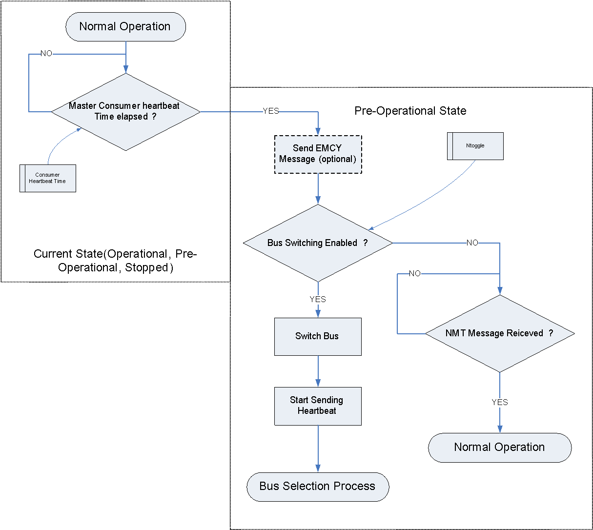 Figure 82: Bus monitoring logic
When an NMT message is detected on a particular bus, the slave shall consider that bus the active one.
In case no NMT message is received on the selected bus after Ttoggle Master Heartbeat consumer times, a slave node shall switch to the alternative bus, while still in Pre-operational, start producing heartbeat on that bus, and then listen for NMT messages.
A slave node shall perform bus toggling as specified in 8.3.3b. for a predefined number of times.
Ntoggle parameters specifies the number of bus switches.
If no NMT message is detected after Ntoggle bus switches, the node shall stop toggling and remain listening on the bus which is, after an even number of togglings, the one defined by the Bdefault parameter.
The bus selection process shall end when an active bus is found.
If requirement 8.3.3k is met, the value of the Bdefault parameter shall be updated to the new active bus.
Figure 83 illustrates the overall bus selection process.
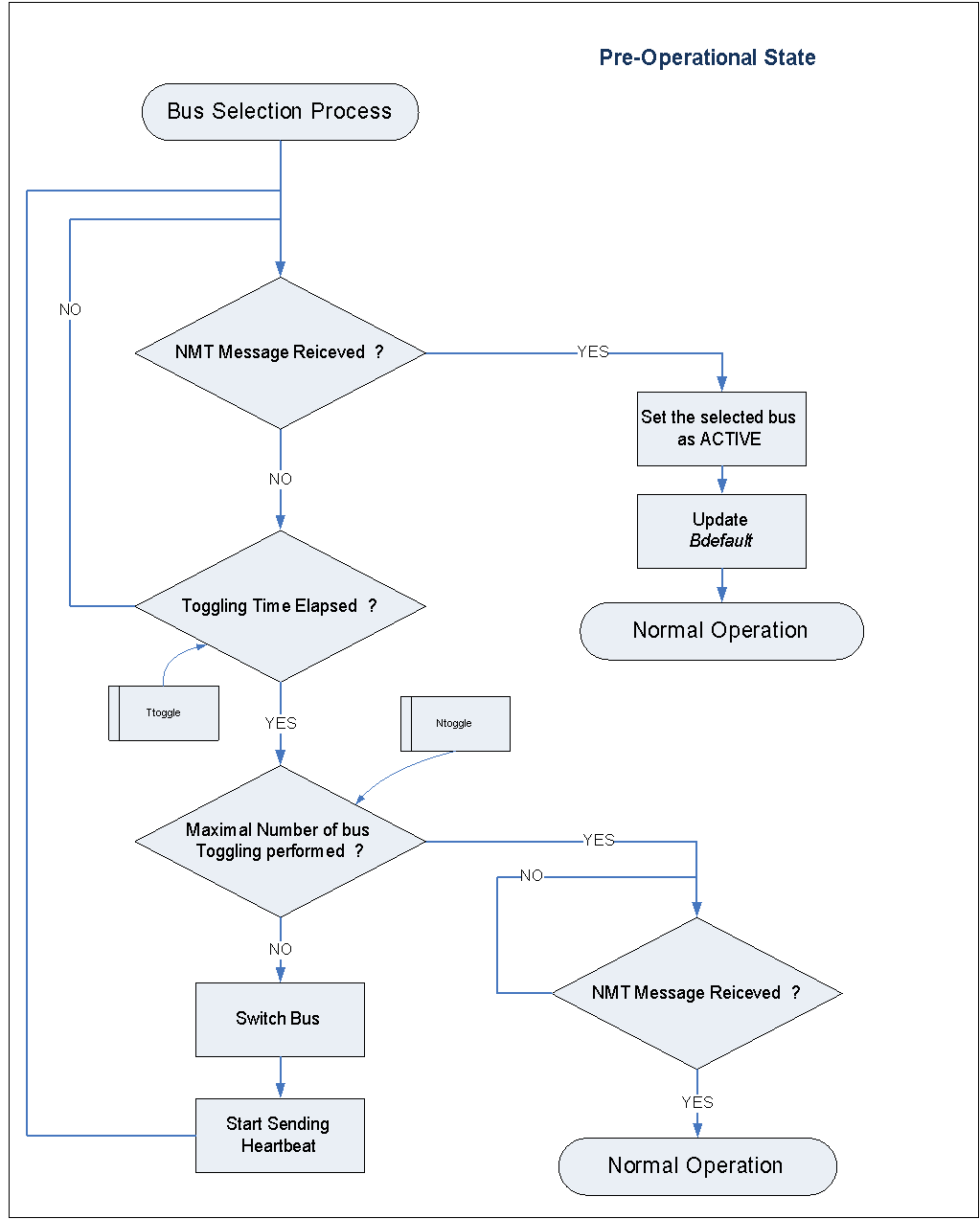 Figure 83: Slave bus selection process, toggling mechanism
Minimal implementation of the CANopen protocol for highly asymmetrical control applications
COB-ID assignment
The address(es) of the master(s) shall have the highest priority(ies).
Slave node address ID(6).. ID(0) assigned to each node shall conform to clause 10 of this document.
NODE-ID 0 is used to broadcast all nodes in the network. It does not use it.
### Object dictionary
An Electronic Data Sheet shall be provided for each CAN Network connected system with a description of all CANopen objects of the device, in a structure corresponding to the CANopen application layer requirements, including index and sub–index.
To reduce memory requirements it is not necessary to embed a full dynamic dictionary of objects including their indexes and mapping. In other terms, it is acceptable that the CANopen objects described in this specification are hard–coded in a way defined by the node implementer, and are not accessible through SDO.
Minimal set CANopen Objects
The minimal set of CANopen Objects as defined in Table 91 and Table 92 shall be implemented based on a restriction of the pre-defined master/slave connection set of objects, with the exception of the time stamp object.
NOTE: NOTE In the Minimal Set Implementation only 4 (Transmit) + 4 (receive) PDOs are implemented. Additionally SDOs can be used, but are not stricly necessary, for in-flight operations. Table 91: Peer-to-Peer objects of the minimal set
|
Object |
Function code (ID-bits 10-7) |
COB –ID |
Communication parameters at OD index (hexa) |
|
|
Calculation (hexa) |
Range identifier (hexa) |
|||
|
PDO 1 (transmit) |
0011 |
180 + Node ID |
181 - 1FF |
1800 |
|
PDO 1 (receive) |
0100 |
200 + Node ID |
201 - 27F |
1400 |
|
PDO 2 (transmit) |
0101 |
280 + Node ID |
281 - 2FF |
1801 |
|
PDO 2 (receive) |
0110 |
300 + Node ID |
301 - 37F |
1401 |
|
PDO 3 (transmit) |
0111 |
380 + Node ID |
381 - 3FF |
1802 |
|
PDO 3 (receive) |
1000 |
400 + Node ID |
401 - 47F |
1402 |
|
PDO 4 (transmit) |
1001 |
480 + Node ID |
481 - 4FF |
1803 |
|
PDO 4 (receive) |
1010 |
500 + Node ID |
501 - 57F |
1403 |
|
NMT Error Control |
1110 |
700 + Node ID |
701 - 77F |
1016, 1017 |
Table 92: Broadcast objects of the minimal set
|
Object |
Function code (ID-bits 10-7) |
Resulting COB-IDs (hexa) |
Communication parameters at OD Index (hexa) |
|
SYNC |
0001 |
80 |
1005, 1006, 1007 |
Minimal Set Protocol
Definitions
Communication between master and slave nodes shall be as shown in Figure 91 and Figure 92:
- 1 The transmission of configuration data or commands to a slave, is called unconfirmed command.
- 2 The start of a data transmission from slave is called telemetry request.
 Figure 91: Unconfirmed Command exchange overview (example with PDO1)
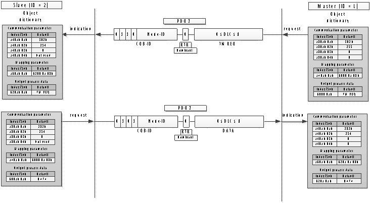 Figure 92: Telemetry request exchange overview (example with PDO2)
The NMT Master shall be the only initiator for data/command exchanges.
For unconfirmed command exchanges, the slave unit shall not answer to the command exchange.
The “Inhibit time” and “event time” optional parameters of the PDO object shall not be used.
Use of data bytes in application layer
Both, telemetry requests and unconfirmed command data bytes shall contain the command itself.
NOTE: NOTE Data bytes on telemetry requests or unconfirmed commands are used to identify the process to be performed by the slave. When telemetry request data bytes are used to request telemetry from the slave, the data bytes shall contain the telemetry register(s) to be returned with the corresponding Data Transmission.
The use of the function code to trigger a process or to trigger a Data Transmission can be used.
A single PDO (PDO 1 for example) can be used as an unconfirmed command and at the same time as a TM request, the process (command or TM request) being identified by the data bytes of the unconfirmed command/TM request.
The master shall be able to process any of the four available PDOs to send unconfirmed commands or TM requests.
The PDO communication parameter object used for an unconfirmed command shall correspond to the structure and entries as defined in Table 93 and Table 94.
Table 93: PDO Communication Object description:
|
Index |
Name |
Object Code |
Data Type |
Category |
|
1400h, 1401h, 1402h, 1403h, |
receive PDO i parameter |
RECORD |
PDO CommPar (20h) |
m |
Table 94: PDO Communication Entry Description:
|
Index |
Sub-Index |
Description |
Data Type |
Entry Cat. |
Acc. |
PDO Mapping |
|
Default Value |
|
1400h, 1401h, 1402h, 1403h |
0h |
number of entries |
U8 |
m |
ro |
No |
2 - 5 |
2 |
|
|
1h |
COB-ID |
U32 |
m |
ro |
No |
U32 |
Index 1400h: 200h + NODE-ID, Index 1401h: 300h + NODE-ID, Index 1402h: 400h + NODE-ID, Index 1403h: 500h + NODE-ID |
|
|
2h |
transmission type |
U8 |
m |
ro |
No |
U8 |
254 |
The value of the transmission type sub-index shall be 254.
NOTE: NOTE TPDOs transmission type 254 specifies that the application event is “manufacturer specific”.
Minimal Set Protocol data transmission
Data transmission exchange,as described in Figure 92, shall be used by the master to download from a slave the data requested by a telemetry request.
Data transmission exchange shall be triggered by either :
- a Telemetry Request message,
- or a SYNC message. In the case specified in 9.4.3b.1, the slave unit shall not send a spontaneous message.
PDO transmit triggered by telemetry request
The time delay between Telemetry Request and the returned Data Transmission shall be defined in the application layer specification.
The optional parameters “Inhibit time” and “event time” of PDO shall not be used.
The PDO communication parameter object relative to a Data Transmission triggered by a Telemetry Request shall correspond to the structure and entries defined in Table 95 and Table 96.
The value of the transmission type sub-index shall be 254.
Table 95 PDO Communication Object description:
|
Index |
Name |
Object Code |
Data Type |
Category |
|
1801h, 1802h, 1803h, 1804h |
Transmit PDO i parameter |
RECORD |
PDO CommPar (20h) |
m |
Table 96: PDO Communication Entry Description:
|
Index |
Sub-Index |
Description |
Data Type |
Entry Cat. |
Acc. |
PDO Mapping |
|
Default Value |
|
1801h, 1802h, 1803h, 1804h |
0h |
number of entries |
U8 |
m |
ro |
No |
2 - 5 |
2 |
|
|
1h |
COB-ID |
U32 |
m |
ro |
No |
U32 |
Index 1800h: 180h + NODE-ID, Index 1801h: 280h + NODE-ID, Index 1802h: 380h + NODE-ID, Index 1803h: 480h + NODE-ID, |
|
|
2h |
transmission type |
U8 |
m |
ro |
No |
U8 |
254 |
PDO mapping
Slave units shall not use variable mapping and dynamic mapping of PDOs.
- 1 Variable mapping of PDOs is re-mapping done in the NMT state Pre-Operational.
- 2 Dynamic mapping is re-mapping of PDOs on the fly.
Network management objects
Module control services
Autonomous operations of slave nodes shall not be used.
This implies that the use of remote node start, stop, enter pre-operational, reset and reset communication services is forbidden.
Special function objects
Time stamp objects
Slaves shall not produce or consume Time Stamp messages.
The master shall not try to read or write Time Stamp messages.
Emergency objects
Slaves shall not produce or consume emergency objects.
No condition shall trigger an Emergency message within the slave node.
SYNC objects
The communication parameter object for the SYNC shall correspond to the structure and entries as specified in Table 97 and Table 98:
Table 97 : SYNC Message Object description:
|
Index |
Name |
Object Code |
Data Type |
Category |
|
1005h |
COB-ID SYNC |
VAR |
UNSIGNED32 |
c |
Table 98: SYNC Message Entry Description:
|
Index |
Sub-Index |
Description |
Data Type |
Entry Cat. |
Acc. |
PDO Mapping |
|
Default Value |
|
1005h |
|
|
U32 |
c |
ro |
No |
U32 |
8000 0080h for master 80h for slave |
When an NMT master uses the SYNC object to cyclically request data transmission, the following conditions shall be met:
- the communication cycle period is identified in its dictionary of objects, and
- the communication cycle period is in accordance with Table 99 and Table 910. Table 99 SYNC used with NMT master Object description:
|
Index |
Name |
Object Code |
Data Type |
Category |
|
1006h |
Communication cycle period |
VAR |
U32 |
c (m for SYNC producer) |
Table 910 SYNC used with NMT master Entry Description:
|
Index |
Sub-Index |
Description |
Data Type |
Entry Cat. |
Acc. |
PDO Mapping |
|
Default Value |
|
1006h |
|
|
U32 |
c |
ro |
No |
U32 |
TBD |
The default value shall be defined by the subcontractor of the NMT master and correspond to the cycle period.
The synchronous windows length time shall not be used.
The synchronous windows length time is the interval during which a node is required to send the TPDO triggered by a SYNC message, and is specified by index 1007h.
Communication error object
In case of protocol error on a received message, the slave unit shall not process the message and not answer by an “Abort SDO Transfer Service” message.
NMT error control objects
Heartbeat service
General
Heartbeat may be used by slave nodes to perform autonomous bus selection.
See also Annex A.4 "Bus management and redundancy".
Bootup service
Nodes shall not produce Bootup Service messages.
Miscellaneous authorized objects
Other objects described in the CANopen protocol may be used in the minimal set as defined in clause 6.
These are objects which are only ‘informative’ and do not lead to the addition of protocol inside the device.
Nodes shall comply with the list of authorized/forbidden objects as defined in Table 911 and Table 912.
If forbidden objects exist in a device, they shall not be used.
If forbidden objects exist in a device, their default values shall be set to the unused value.
If in Table 912 a device supports PDOs, the according PDO communication parameter and PDO mapping entries in the Object dictionary shall be implemented.
The Object dictionary can be read-only.
If in Table 912 a device supports SDOs, the according SDO parameters in the Object dictionary shall be implemented.
Table 911: CANopen Object dictionary Data Types
|
Index |
Object |
Name |
Status |
|
0001 |
DEFTYPE |
BOOLEAN |
Requested |
|
0002 |
DEFTYPE |
INTEGER8 |
Requested |
|
0003 |
DEFTYPE |
INTEGER16 |
Requested |
|
0004 |
DEFTYPE |
INTEGER32 |
Requested |
|
0005 |
DEFTYPE |
UNSIGNED8 |
Requested |
|
0006 |
DEFTYPE |
UNSIGNED16 |
Requested |
|
0007 |
DEFTYPE |
UNSIGNED32 |
Requested |
|
0008 |
DEFTYPE |
REAL32 |
Authorized |
|
0009 |
DEFTYPE |
VISIBLE_STRING |
|
|
000A |
DEFTYPE |
OCTET_STRING |
Requested |
|
000B |
DEFTYPE |
UNICODE_STRING |
Authorized |
|
000C |
DEFTYPE |
TIME_OF_DAY |
Authorized |
|
000D |
DEFTYPE |
TIME_DIFFERENCE |
Authorized |
|
000E |
DEFTYPE |
reserved |
|
|
000F |
DEFTYPE |
DOMAIN |
Authorized |
|
0010 |
DEFTYPE |
INTEGER24 |
Authorized |
|
0011 |
DEFTYPE |
REAL64 |
Authorized |
|
0012 |
DEFTYPE |
INTEGER40 |
Authorized |
|
0013 |
DEFTYPE |
INTEGER48 |
Authorized |
|
0014 |
DEFTYPE |
INTEGER56 |
Authorized |
|
0015 |
DEFTYPE |
INTEGER64 |
Authorized |
|
0016 |
DEFTYPE |
UNSIGNED24 |
Authorized |
|
0017 |
reserved |
|
|
|
0018 |
DEFTYPE |
UNSIGNED40 |
Authorized |
|
0019 |
DEFTYPE |
UNSIGNED48 |
Authorized |
|
001A |
DEFTYPE |
UNSIGNED56 |
Authorized |
|
001B |
DEFTYPE |
UNSIGNED64 |
Authorized |
|
001C-001F |
reserved |
|
|
|
0020 |
DEFSTRUCT |
PDO_COMMUNICATION_PARAMETER |
Requested |
|
0021 |
DEFSTRUCT |
PDO_MAPPING |
Requested |
|
0022 |
DEFSTRUCT |
SDO_PARAMETER |
Authorized |
|
0023 |
DEFSTRUCT |
IDENTITY |
Authorized |
|
0024-003F |
reserved |
|
|
|
0040-005F |
DEFSTRUCT |
Manufacturer Specific Complex Data Types |
Authorized |
|
0060-007F |
DEFTYPE |
Device Profile (0) Specific Standard Data Types |
Authorized |
|
0080-009F |
DEFSTRUCT |
Device Profile (0) Specific Complex Data Types |
Authorized |
|
00A0-00BF |
DEFTYPE |
Device Profile 1 Specific Standard Data Types |
Authorized |
|
00C0-00DF |
DEFSTRUCT |
Device Profile 1 Specific Complex Data Types |
Authorized |
|
00E0-00FF |
DEFTYPE |
Device Profile 2 Specific Standard Data Types |
Authorized |
|
0100-011F |
DEFSTRUCT |
Device Profile 2 Specific Complex Data Types |
Authorized |
|
0120-013F |
DEFTYPE |
Device Profile 3 Specific Standard Data Types |
Authorized |
|
0140-015F |
DEFSTRUCT |
Device Profile 3 Specific Complex Data Types |
Authorized |
|
0160-017F |
DEFTYPE |
Device Profile 4 Specific Standard Data Types |
Authorized |
|
0180-019F |
DEFSTRUCT |
Device Profile 4 Specific Complex Data Types |
Authorized |
|
01A0-01BF |
DEFTYPE |
Device Profile 5 Specific Standard Data Types |
Authorized |
|
01C0-01DF |
DEFSTRUCT |
Device Profile 5 Specific Complex Data Types |
Authorized |
|
01E0-01FF |
DEFTYPE |
Device Profile 6 Specific Standard Data Types |
Authorized |
|
0200-021F |
DEFSTRUCT |
Device Profile 6 Specific Complex Data Types |
Authorized |
|
0220-023F |
DEFTYPE |
Device Profile 7 Specific Standard Data Types |
Authorized |
|
0240-025F |
DEFSTRUCT |
Device Profile 7 Specific Complex Data Types |
Authorized |
Table 912: Authorized and Forbidden Object Dictionary Entries of the Communication profile
|
Index (hex) |
Name |
Type |
Access a) |
CANopen Mandatory/ Optional |
ECSS-E-ST-50-15 application |
|
1000 |
device type |
UNSIGNED32 |
ro |
M |
Authorized |
|
1001 |
error register |
UNSIGNED8 |
ro |
M |
Authorized |
|
1002 |
manufacturer status register |
UNSIGNED32 |
ro |
O |
Authorized |
|
1003 |
pre-defined error field |
UNSIGNED32 |
ro |
O |
Authorized |
|
1004 |
reserved for compatibility reasons |
||||
|
1005 |
COB-ID SYNC |
UNSIGNED32 |
rw |
O |
Authorized |
|
1006 |
communication cycle period |
UNSIGNED32 |
rw |
O |
Authorized |
|
1007 |
synchronous window length |
UNSIGNED32 |
rw |
O |
Forbidden |
|
1008 |
manufacturer device name |
Vis-String |
const |
O |
Authorized |
|
1009 |
manufacturer hardware version |
Vis-String |
const |
O |
Authorized |
|
100A |
manufacturer software version |
Vis-String |
const |
O |
Authorized |
|
100B |
reserved for compatibility reasons |
||||
|
100C |
guard time |
UNSIGNED16 |
rw |
O |
Forbidden |
|
100D |
life time factor |
UNSIGNED8 |
rw |
O |
Forbidden |
|
100E |
reserved for compatibility reasons |
||||
|
100F |
reserved for compatibility reasons |
||||
|
1010 |
store parameters |
UNSIGNED32 |
rw |
O |
Forbidden |
|
1011 |
restore default parameters |
UNSIGNED32 |
rw |
O |
Forbidden |
|
1012 |
COB-ID TIME |
UNSIGNED32 |
rw |
O |
Forbidden |
|
1013 |
high resolution time stamp |
UNSIGNED32 |
rw |
O |
Forbidden |
|
1014 |
COB-ID EMCY |
UNSIGNED32 |
rw |
O |
Forbidden |
|
1015 |
Inhibit Time EMCY |
UNSIGNED16 |
rw |
O |
Forbidden |
|
1016 |
Consumer heartbeat time |
UNSIGNED32 |
rw |
O |
Authorized |
|
1017 |
Producer heartbeat time |
UNSIGNED16 |
rw |
O |
Authorized |
|
1018 |
Identity Object |
Identity (23h) |
ro |
M |
Authorized |
|
1019 |
reserved |
|
|
|
|
|
::::: |
::::: |
::::: |
::::: |
::::: |
::::: |
|
11FF |
reserved |
|
|
|
|
|
1200 |
1st Server SDO parameter |
SDO Parameter (22h) |
ro |
O |
Authorized only for test after agreement |
|
1201 |
2nd Server SDO parameter |
SDO Parameter (22h) |
rw |
M/O |
Forbidden |
|
::::: |
::::: |
::::: |
::::: |
::::: |
::::: |
|
127F |
128th Server SDO parameter |
SDO Parameter (22h) |
rw |
M/O |
Forbidden |
|
1280 |
1st Client SDO parameter |
SDO Parameter (22h) |
rw |
M/O |
Authorized only for test after agreement |
|
1281 |
2nd Client SDO parameter |
SDO Parameter (22h) |
rw |
M/O |
Forbidden |
|
::::: |
::::: |
::::: |
::::: |
::::: |
::::: |
|
12FF |
128th Client SDO parameter |
SDO Parameter (22h) |
rw |
M/O |
Forbidden |
|
1300 |
reserved |
|
|
|
|
|
::::: |
::::: |
::::: |
::::: |
::::: |
::::: |
|
13FF |
reserved |
|
|
|
|
|
1400 |
1st Receive PDO Parameter |
PDO CommPar (20h) |
rw |
M/O |
Authorized |
|
1401 |
2nd Receive PDO Parameter |
PDO CommPar (20h) |
|
M/O |
Authorized |
|
1402 |
3rd Receive PDO Parameter |
|
|
|
Authorized |
|
1403 |
4th Receive PDO Parameter |
|
|
|
Authorized |
|
1404 |
5th Receive PDO Parameter |
|
|
|
Forbidden |
|
::::: |
::::: |
::::: |
::::: |
::::: |
::::: |
|
15FF |
512th Receive PDO Parameter |
PDO CommPar (20h) |
rw |
M/O |
Forbidden |
|
1600 |
1st Receive PDO mapping |
PDO Mapping (21h) |
rw |
M/O |
Authorized |
|
1601 |
2nd Receive PDO mapping |
PDO Mapping (21h) |
rw |
M/O |
Authorized |
|
1602 |
3rd Receive PDO mapping |
|
|
|
Authorized |
|
1603 |
4th Receive PDO mapping |
|
|
|
Authorized |
|
1604 |
5th Receive PDO mapping |
|
|
|
Forbidden |
|
::::: |
::::: |
::::: |
::::: |
::::: |
::::: |
|
17FF |
512th Receive PDO mapping |
PDO Mapping (21h) |
rw |
M/O |
Forbidden |
|
1800 |
1st transmit PDO Parameter |
PDO CommPar (20h) |
rw |
M/O |
Authorized |
|
1801 |
2nd transmit PDO Parameter |
PDO CommPar (20h) |
rw |
M/O |
Authorized |
|
1802 |
3rd transmit PDO Parameter |
|
|
|
Authorized |
|
1803 |
4th transmit PDO Parameter |
|
|
|
Authorized |
|
1804 |
5th transmit PDO Parameter |
|
|
|
Forbidden |
|
::::: |
::::: |
::::: |
::::: |
:::: |
::::: |
|
19FF |
512th transmit PDO Parameter |
PDO CommPar (20h) |
rw |
M/O |
Forbidden |
|
1A00 |
1st transmit PDO mapping |
PDO Mapping (21h) |
rw |
M/O |
Authorized |
|
1A01 |
2nd transmit PDO mapping |
PDO Mapping (21h) |
rw |
M/O |
Authorized |
|
1A02 |
3rd transmit PDO mapping |
PDO Mapping (21h) |
rw |
M/O |
Authorized |
|
1A03 |
4th transmit PDO mapping |
PDO Mapping (21h) |
rw |
M/O |
Authorized |
|
1A04 |
5th transmit PDO mapping |
PDO Mapping (21h) |
rw |
M/O |
Forbidden |
|
::::: |
::::: |
::::: |
::::: |
::::: |
::::: |
|
1BFF |
512th transmit PDO mapping |
PDO Mapping (21h) |
rw |
M/O |
Forbidden |
|
a) Access type listed here can vary for certain sub-indices. See detailed object specification. ro = read-only
| |||||
Free COB–ID
Free COB–ID (1921 to 2014 and 2032 to 2047) shall not be used.
Table 913 recalls the list of predefined set of objects.
Table 913 : COB ID -Predefined connection set
|
|
function code |
Node address |
COB-ID |
DATA |
|||||||||||||||||
|
|
B10 |
B9 |
B8 |
B7 |
B6 |
B5 |
B4 |
B3 |
B2 |
B1 |
B0 |
decimal |
DLC |
BYTE 0 |
BYTE 1 |
BYTE 2 |
BYTE 3 |
BYTE 4 |
BYTE 5 |
BYTE 6 |
BYTE 7 |
|
NMT |
0 |
0 |
0 |
0 |
0 |
0 |
0 |
0 |
0 |
0 |
0 |
0 |
2 |
CS |
NODE-ID |
X |
X |
X |
X |
X |
X |
|
SYNC |
0 |
0 |
0 |
1 |
0 |
0 |
0 |
0 |
0 |
0 |
0 |
128 |
0 |
X |
X |
X |
X |
X |
X |
X |
X |
|
TIME STAMP |
0 |
0 |
1 |
0 |
0 |
0 |
0 |
0 |
0 |
0 |
0 |
256 |
6 |
Time stamp object |
X |
X |
|||||
|
EMERGENCY |
0 |
0 |
0 |
1 |
0 |
0 |
0 |
0 |
0 |
0 |
1 |
129 |
8 |
error code |
error register |
manufacturer specific |
|||||
|
… |
to |
||||||||||||||||||||
|
1 |
1 |
1 |
1 |
1 |
1 |
1 |
255 |
||||||||||||||
|
RESERVED SRDO |
0 |
0 |
1 |
0 |
0 |
0 |
0 |
0 |
0 |
0 |
1 |
257 |
reserved |
||||||||
|
… |
to |
||||||||||||||||||||
|
1 |
1 |
1 |
1 |
1 |
1 |
1 |
383 |
||||||||||||||
|
0 |
0 |
1 |
1 |
0 |
0 |
0 |
0 |
0 |
0 |
0 |
384 |
||||||||||
|
TPDO1 |
0 |
0 |
1 |
1 |
0 |
0 |
0 |
0 |
0 |
0 |
1 |
385 |
0 to 8 |
manufacturer specific |
|||||||
|
… |
to |
||||||||||||||||||||
|
1 |
1 |
1 |
1 |
1 |
1 |
1 |
511 |
||||||||||||||
|
RPDO1 |
0 |
1 |
0 |
0 |
0 |
0 |
0 |
0 |
0 |
0 |
1 |
513 |
0 to 8 |
manufacturer specific |
|||||||
|
… |
to |
||||||||||||||||||||
|
1 |
1 |
1 |
1 |
1 |
1 |
1 |
639 |
||||||||||||||
|
TPDO2 |
0 |
1 |
0 |
1 |
0 |
0 |
0 |
0 |
0 |
0 |
1 |
641 |
0 to 8 |
manufacturer specific |
|||||||
|
… |
to |
||||||||||||||||||||
|
1 |
1 |
1 |
1 |
1 |
1 |
1 |
767 |
||||||||||||||
|
RPDO2 |
0 |
1 |
1 |
0 |
0 |
0 |
0 |
0 |
0 |
0 |
1 |
769 |
0 to 8 |
manufacturer specific |
|||||||
|
… |
to |
||||||||||||||||||||
|
1 |
1 |
1 |
1 |
1 |
1 |
1 |
895 |
||||||||||||||
|
TPDO3 |
0 |
1 |
1 |
1 |
0 |
0 |
0 |
0 |
0 |
0 |
1 |
897 |
0 to 8 |
manufacturer specific |
|||||||
|
… |
to |
||||||||||||||||||||
|
1 |
1 |
1 |
1 |
1 |
1 |
1 |
1023 |
||||||||||||||
|
RPDO3 |
1 |
0 |
0 |
0 |
0 |
0 |
0 |
0 |
0 |
0 |
1 |
1025 |
0 to 8 |
manufacturer specific |
|||||||
|
… |
to |
||||||||||||||||||||
|
1 |
1 |
1 |
1 |
1 |
1 |
1 |
1151 |
||||||||||||||
|
TPDO4 |
1 |
0 |
0 |
1 |
0 |
0 |
0 |
0 |
0 |
0 |
1 |
1153 |
0 to 8 |
manufacturer specific |
|||||||
|
… |
to |
||||||||||||||||||||
|
1 |
1 |
1 |
1 |
1 |
1 |
1 |
1279 |
||||||||||||||
|
RPDO4 |
1 |
0 |
1 |
0 |
0 |
0 |
0 |
0 |
0 |
0 |
1 |
1281 |
0 to 8 |
manufacturer specific |
|||||||
|
… |
to |
||||||||||||||||||||
|
1 |
1 |
1 |
1 |
1 |
1 |
1 |
1407 |
||||||||||||||
|
SDO tx |
1 |
0 |
1 |
1 |
0 |
0 |
0 |
0 |
0 |
0 |
1 |
1409 |
0 to oo |
manufacturer specific |
|||||||
|
… |
to |
||||||||||||||||||||
|
1 |
1 |
1 |
1 |
1 |
1 |
1 |
1535 |
||||||||||||||
|
SDO rx |
1 |
1 |
0 |
0 |
0 |
0 |
0 |
0 |
0 |
0 |
1 |
1537 |
0 to oo |
manufacturer specific |
|||||||
|
… |
to |
||||||||||||||||||||
|
1 |
1 |
1 |
1 |
1 |
1 |
1 |
1663 |
||||||||||||||
|
NMT error control |
1 |
1 |
1 |
0 |
0 |
0 |
0 |
0 |
0 |
0 |
1 |
1793 |
1 |
t & s |
X |
X |
X |
X |
X |
X |
X |
|
… |
to |
||||||||||||||||||||
|
1 |
1 |
1 |
1 |
1 |
1 |
1 |
1919 |
||||||||||||||
|
FREE |
1 |
1 |
1 |
1 |
0 |
0 |
0 |
0 |
0 |
0 |
1 |
1921 |
manufacturer specific |
||||||||
|
… |
to |
||||||||||||||||||||
|
1 |
0 |
1 |
1 |
1 |
1 |
0 |
2014 |
||||||||||||||
|
RESERVED NMT, LMT, DBT |
1 |
0 |
1 |
1 |
1 |
1 |
1 |
2015 |
Reserved |
||||||||||||
|
… |
|
||||||||||||||||||||
|
1 |
1 |
0 |
1 |
1 |
1 |
1 |
2031 |
||||||||||||||
|
FREE |
1 |
1 |
1 |
0 |
0 |
0 |
0 |
2032 |
manufacturer specific |
||||||||||||
|
… |
to |
||||||||||||||||||||
|
1 |
1 |
1 |
1 |
1 |
1 |
1 |
2047 |
||||||||||||||
Connectors and pin assignments
Overview
This clause specifies the connector types and pin allocations to be used for connecting the CAN physical layer.
Naming convention
Connectors not mentioned in this document, shall be named in the project’s specific interface documents using the terminology as defined in Table 101.
Table 101 : Signal terminology
|
Signal description
|
Notation
|
|
CAN_L bus line (dominant low)
|
CAN_L
|
|
CAN_H bus line (dominant high)
|
CAN_H
|
|
CAN ground
|
CAN_GND
|
|
Optional CAN shield
|
CAN_SHLD
|
|
Optional CAN external positive supply
|
CAN_V+
|
|
Optional ground
|
GND
|
Circular connectors
MIL-C D38999 configuration B: Dual CAN Network
The connector shall be compliant to specification MIL-C D38999 Series 3.
The connector shall not use a non-conductive finish as specified in requirement 4.2.13.2c.1 of ECSS-E-ST-20-07.
The shell size shall be A.
The pin layout shall be 35 (6 pin).
The key orientation shall be A.
The pin function shall be according to Table 102.
The appropriate gender selection of 10.3.1a is specified in clause 5.2.2.
Table 102: Pin function for MIL-C D38999 configuration B
|
Pin No
|
Function
|
|
1
|
CAN_H (PRIMARY)
|
|
2
|
CAN_L (PRIMARY)
|
|
3
|
Reserved
|
|
4
|
CAN_H (REDUNDANT)
|
|
5
|
CAN_L (REDUNDANT)
|
|
6
|
Reserved
|
MIL-C D38999 configuration D: Single CAN Network
The connector shall be compliant to specification: MIL-C D38999 Series 3.
The connector shall not use a non-conductive finish as specified in requirement 4.2.13.2c.1 of ECSS-E-ST-20-07.
The shell size shall be A and the pin layout shall be 98 (3 pin).
The key orientation for the primary bus shall be N.
The key orientation for the secondary bus shall be A.
The pin function shall be according to Table 103.
The appropriate gender selection of 10.3.2a is specified in clause 5.2.2.
Table 103: Pin function for MIL-C D38999 configuration D
|
Pin No
|
Function
|
|
1
|
CAN_H
|
|
2
|
CAN_L
|
|
3
|
Reserved
|
Sub-miniature D connectors (9-pin D-sub)
The connector shall be a nine contact micro-miniature D-type with solder contacts, as defined in ESCC 3401/029, or crimp contacts.
Connector shall be compliant to: sub-miniature D type.
A 9-pin D-Sub connector DIN41652 (1990-06) should be used.
See also Figure 101.
 Figure 101: Illustration of a 9-pin D-Sub connector
The pin function shall be according to CiA102 and CiA 303-1 [10] [26].
For convenience the pinning is repeated here in Table 104.
Table 104: Pin function for sub D-type with CAN Network
|
Pin No
|
Signal Name
|
Function
|
|
1
|
-
|
Reserved
|
|
2
|
CAN_L
|
CAN_L bus line dominant low
|
|
3
|
CAN_GND
|
CAN Ground (OPTIONAL)
|
|
4
|
-
|
Reserved
|
|
5
|
(CAN_SHLD)
|
CAN Shield (OPTIONAL)
|
|
6
|
(GND)
|
Ground (OPTIONAL)
|
|
7
|
CAN_H
|
CAN_H bus line dominant high
|
|
8
|
-
|
Reserved (Some commercial systems may use pin 8 as an error line, to indicate an error on the net).
|
|
9
|
(CAN_V+)
|
CAN_V+ - CAN external supply (OPTIONAL)
|
If a 9-pin D-Sub connector is supported, and if CAN ground connections are used, within the units pin 3 and pin 6 shall be interconnected.
If an error line is needed within a system, then pin 8 shall be used for this purpose.
Pin assignment in micro miniature D shell shall be as specified in Table 104, provided that the connector is a nine contact micro-miniature D-type with solder contacts, as defined in ESCC 3401/071, or crimp contacts.
The appropriate gender selection ‘z’ is specified in clause 5.2.2.
Sub-miniature D connectors (9-pin D-sub) – RS-485
The connector shall be a nine contact micro-miniature D-type with solder contacts, as defined in ESCC 3401/029, or crimp contacts.
The appropriate gender selection of 10.5a is specified in clause 5.2.2.
Connector shall be compliant to specification: sub-miniature D type.
- 1 It is recommended to use a 9-pin D-Sub connector DIN 41652 (1990-06) or corresponding international standard).
- 2 The pin function for RS-485 CAN Network is custom, and does not comply with the commercial standard as defined in Table 105.
If an error line is needed within a system, then pin 8 shall be used for this purpose.
Pin assignment in micro miniature D shell shall be as specified in Table 105, provided that the connector is a nine contact micro-miniature D-type with solder contacts, as defined in ESCC 3401/071, or crimp contacts.
Table 105: Pin function for sub D-type with RS-485 CAN Network
|
Pin No
|
Signal Name
|
Function
|
|
1
|
CAN_H (485)
|
CAN_H bus line dominant high MAIN LINE
|
|
2
|
-
|
Reserved
|
|
3
|
CAN_GND
|
CAN Ground (OPTIONAL)
|
|
4
|
-
|
Reserved
|
|
5
|
CAN_L RED (485)
|
CAN_L bus line dominant low MAIN LINE
|
|
6
|
CAN_L (485)
|
CAN_L bus line dominant low RED LINE
|
|
7
|
-
|
Reserved
|
|
8
|
-
|
Reserved
|
|
9
|
CAN_H RED (485)
|
CAN_H bus line dominant high RED LINE
|
CANopen standard applicability matrix
Introduction
In order to provide guidance on the implementation of the CANopen standard, Table 111 identifies the applicability of the features of the CANopen standard, as follows:
Sections identified with an “A” are applicable, with the conditions and limitations stated in the column “Notes”.
Sections identified with an “O” (optional) are applicable only if so decided by the implementer.
All the sections identified with an “NA” are not used.
All sections identified with an “R” are for reference only.
Table 111: DiA 301 (former CIA DS301) applicability matrix
|
section or subsection in CiA DS301
|
name/reference
|
ECSS-E-ST-50-15C
|
Notes
| |
|
R => for Reference only
|
A => Applicable
| |||
|
3
|
Definition and Abbreviation
|
R
|
|
|
|
4
|
Modelling
|
R
|
|
|
|
5
|
Physical Layer
|
|
|
|
|
5.3
|
Physical medium attachment
|
NA
|
The Physical Medium Attachment (transceiver) to be implemented in accordance with the specifications of this ECSS standard.
| |
|
5.4
|
Physical signalling
|
A
|
|
|
|
6
|
Data Link Layer
|
A
|
|
|
|
7
|
APPLICATION LAYER
|
|
|
|
|
7.1
|
Data Types and Encoding Rules
|
|
|
|
|
7.1.1
|
General Description of Data Types and Encoding Rules
|
NA
|
See req: 6.9b
| |
|
7.1.2
|
Data Type Definitions
|
R
|
|
|
|
7.1.3
|
Bit Sequences
|
|
|
|
|
7.1.3.1
|
Definition of Bit Sequences
|
A
|
|
|
|
7.1.3.2
|
Transfer Syntax for Bit Sequences
|
A
|
|
|
|
7.1.4
|
Basic Data Types
|
A
|
|
|
|
7.1.5
|
Compound Data Types
|
A
|
|
|
|
7.1.6
|
Extended Data Types
|
A
|
|
|
|
7.2
|
Communication Objects
|
|
|
|
|
7.2.1
|
Process Data Object (PDO)
|
A
|
|
|
|
7.2.2.2
|
Transmission Modes
|
A
|
|
|
|
7.2.2.3
|
Triggering Modes
|
|
|
|
|
|
Event and Timer Driven
|
A
|
|
|
|
|
Synchronously Triggered
|
A
|
|
|
|
|
Remotely requested
|
NA
|
This triggering mechanism is not required.
| |
|
7.2.2.4
|
PDO Services
|
|
|
|
|
7.2.2.4.2
|
PDO write
|
A
|
|
|
|
7.2.2.4.3
|
Read PDO
|
NA
|
The pull model foresee the RTR features which is not required; therefore no Read PDO can be implemented
| |
|
7.2.2.5
|
PDO Protocol
|
|
|
|
|
7.2.2.5.1
|
Write PDO Protocol
|
A
|
|
|
|
7.2.2.5.2
|
Read PDO Protocol
|
NA
|
The pull model foresee the RTR features which is not required; therefore no Read PDO can be implemented
| |
|
7.2.3
|
Multiplex PDO (MPDO)
|
NA
|
|
|
|
7.2.4
|
Service Data Object (SDO)
|
O
|
In the CANopen standard Expedited SDO is mandatory and the Segmented SDO is mandatory for Objects larger than 4 bytes. In this ECSS standard SDOs are optional
| |
|
7.2.4.1
|
General
|
A
|
Only one SDO server has been required for each node; therefore the SSDO communication parameter is omitted (1200h + SSDOnumber-1)
| |
|
7.2.4.2
|
SDO Services
|
O
|
All SDO services are optional in this standard
| |
|
7.2.4.2.2
|
SDO Download
|
A
|
If the segmented SDO service is implemented, implementation of the Size field is mandatory.
| |
|
7.2.4.2.3
|
Service SDO download initiate
|
A
|
If the segmented SDO service is implemented; implementation of the Size field is mandatory.
| |
|
7.2.4.2.4
|
Service SDO download segment
|
A
|
If the segmented SDO service is implemented; implementation of the Size field is mandatory.
| |
|
7.2.4.2.5
|
Service SDO upload
|
A
|
If the segmented SDO service is implemented; implementation of the Size field is mandatory.
| |
|
7.2.4.2.6
|
Service SDO upload initiate
|
A
|
If the segmented SDO service is implemented; implementation of the Size field is mandatory.
| |
|
7.2.4.2.7
|
Service SDO upload segment
|
A
|
If the segmented SDO service is implemented; implementation of the Size field is mandatory.
| |
|
7.2.4.2.8
|
Service SDO block download
|
A
|
If the block SDO service is implemented; implementation of the Size field is mandatory.
| |
|
7.2.4.2.9
|
Service SDO block download initiate
|
A
|
If the block SDO service is implemented; implementation of the Size field is mandatory.
| |
|
7.2.4.2.10
|
Service SDO block download sub-block
|
A
|
If the block SDO service is implemented; implementation of the Size field is mandatory.
| |
|
7.2.4.2.11
|
Service SDO block download end
|
A
|
If the block SDO service is implemented; implementation of the Size field is mandatory.
| |
|
7.2.4.2.12
|
Service SDO block upload
|
A
|
If the block SDO service is implemented; implementation of the Size field is mandatory.
| |
|
7.2.4.2.13
|
Service SDO block upload initiate
|
A
|
If the block SDO service is implemented; implementation of the Size field is mandatory.
| |
|
7.2.4.2.14
|
Service SDO block upload sub-block
|
A
|
If the block SDO service is implemented; implementation of the Size field is mandatory.
| |
|
7.2.4.2.15
|
Service SDO block upload end
|
A
|
If the block SDO service is implemented; implementation of the Size field is mandatory.
| |
|
7.2.4.3
|
SDO Protocols
|
A
|
Only the following expedited SDO service is mandatory; the other SDO services are considered mission dependent.
| |
|
7.2.4.3.2
|
Protocol SDO download
|
A
|
|
|
|
7.2.4.3.3
|
Protocol SDO download initiate
|
A
|
|
|
|
7.2.4.3.4
|
Protocol SDO download segment
|
A
|
Applicable if the segmented SDO protocol service is implemented
| |
|
7.2.4.3.5
|
Protocol SDO upload
|
A
|
Applicable if the segmented SDO protocol service is implemented
| |
|
7.2.4.3.6
|
Protocol SDO upload initiate
|
A
|
Applicable if the segmented SDO protocol service is implemented
| |
|
7.2.4.3.7
|
Protocol SDO upload segment
|
A
|
Applicable if the segmented SDO protocol service is implemented
| |
|
7.2.4.3.8
|
Protocol SDO block download
|
A
|
Applicable if the SDO block transfer protocol service is implemented
| |
|
7.2.4.3.9
|
Protocol SDO block download initiate
|
A
|
Applicable if the SDO block transfer protocol service is implemented
| |
|
7.2.4.3.10
|
Protocol SDO block download sub-block
|
A
|
Applicable if the SDO block transfer protocol service is implemented
| |
|
7.2.4.3.11
|
Protocol SDO block download end
|
A
|
Applicable if the SDO block transfer protocol service is implemented
| |
|
7.2.4.3.12
|
Protocol SDO block upload
|
A
|
Applicable if the SDO block transfer protocol service is implemented
| |
|
7.2.4.3.13
|
Protocol SDO block upload initiate
|
A
|
Applicable if the SDO block transfer protocol service is implemented
| |
|
7.2.4.3.14
|
Protocol SDO block upload sub-block
|
A
|
Applicable if the SDO block transfer protocol service is implemented
| |
|
7.2.4.3.15
|
Protocol SDO block upload end
|
A
|
Applicable if the SDO block transfer protocol service is implemented
| |
|
7.2.4.3.16
|
CRC calculation algorithm to verify SDO Block Transfer
|
NA
|
This type of SDO service is not required.
| |
|
7.2.4.3.17
|
Protocol SDO abort transfer
|
A
|
|
|
|
7.2.5
|
Synchronisation Object (SYNC)
|
A
|
|
|
|
7.2.5.2
|
SYNC Services
|
A
|
|
|
|
7.2.5.3
|
SYNC Protocol
|
A
|
|
|
|
7.2.6
|
Time Stamp Object (TIME)
|
NA
|
The SCET has been selected as the Time exchange format and it is sent by the network master via a common TPDO broadcasted on the network;
| |
|
7.2.6.2
|
TIME Services
|
NA
|
Specific for space use due to peculiar definition of OBT variables. Defined in Chapter 7
| |
|
7.2.6.3
|
TIME Protocol
|
NA
|
Specific for space use due to peculiar definition of OBT variables. Defined in Chapter 7
| |
|
7.2.7
|
Emergency Object (EMCY)
|
NA
|
The EMCY service is not Required.
| |
|
7.2.8
|
Network Management Objects
|
A
|
|
|
|
7.2.8.2
|
NMT services
|
A
|
|
|
|
7.2.8.2.1.2
|
Service start remote node
|
A
|
|
|
|
7.2.8.2.1.3
|
Service stop remote node
|
A
|
|
|
|
7.2.8.2.1.4
|
Service enter pre-operational
|
A
|
|
|
|
7.2.8.2.1.5
|
Service reset node
|
A
|
In addition to what declared into the standard with the Reset Node Service the whole device connected with the CAN controller is reset
| |
|
7.2.8.2.1.6
|
Service Reset Communication
|
A
|
|
|
|
7.2.8.2.2
|
Error Control Services
|
A
|
The CANopen standard specifies either the Heartbeat or Guarding mechanisms as mandatory. In this ECSS standard only implementation of the Heartbeat mechanism is mandatory.
| |
|
7.2.8.2.2.1
|
Service Node Guarding Event
|
NA
|
|
|
|
7.2.8.2.2.2
|
Service Life Guarding Event
|
NA
|
|
|
|
7.2.8.2.2.3
|
Service Heartbeat Event
|
A
|
|
|
|
7.2.8.2.3
|
Bootup Service
|
A
|
|
|
|
7.2.8.3
|
NMT Protocols
|
A
|
|
|
|
7.2.8.3.1
|
Node Control Protocols
|
A
|
|
|
|
7.2.8.3.1.1
|
Protocol Start Remote Node
|
A
|
|
|
|
7.2.8.3.1.2
|
Protocol Stop Remote Node
|
A
|
|
|
|
7.2.8.3.1.3
|
Protocol Enter Pre-Operational
|
A
|
|
|
|
7.2.8.3.1.4
|
Protocol Reset Node
|
A
|
|
|
|
7.2.8.3.1.5
|
Protocol Reset Communication
|
A
|
|
|
|
|
Error Control Protocols
|
|
|
|
|
7.2.8.3.2
|
Error Control Protocols
|
A
|
Only the implementation of the HeartBeat protocol is mandatory.
| |
|
7.2.8.3.2.1
|
Protocol Node Guarding
|
NA
|
|
|
|
7.2.8.3.2.2
|
Protocol Heartbeat
|
A
|
|
|
|
7.2.8.3.3
|
Protocol Boot-up
|
A
|
|
|
|
7.3
|
Network Initialization and System Boot-Up
|
A
|
|
|
|
7.3.1
|
Simplified NMT
|
NA
|
The right sequence is:
| |
|
7.3.2
|
Machine
|
A
|
|
|
|
7.3.2.1
|
Overview
|
A
|
|
|
|
7.3.2.2
|
NMT States
|
|
|
|
|
7.3.2.2.1
|
NMT state Initialisation
|
A
|
|
|
|
|
Initialising
|
A
|
|
|
|
|
Reset_Application
|
A
|
|
|
|
|
Reset_Communication
|
A
|
The possibility to directly go to the OPERATIONAL state after the Reset_communication procedure is also required
| |
|
7.3.2.2.2
|
NMT state Pre-operational
|
A
|
|
|
|
7.3.2.2.3
|
NMT state Operational
|
A
|
|
|
|
7.3.2.2.4
|
NMT state Stopped
|
A
|
|
|
|
7.3.2.2.5
|
NMT states and communication object relation
|
O
|
The Time Stamp Object is not mandatory.
| |
|
7.3.2.3
|
NMT state transitions
|
A
|
|
|
|
7.3.3
|
Generic pre-defined connection set
|
A
|
Table 38 is applicable
| |
|
7.3.4
|
Specific pre-defined connection set
|
R
|
|
|
|
7.3.5
|
Restricted CAN-IDs
|
R
|
|
|
|
7.4
|
Object Dictionary
|
A
|
|
|
|
7.4.1
|
General structure
|
R
|
The general OD structure is used to define the ECSS-E-ST-50-15 users OD, but unused OD entry are not implemented.
| |
|
7.4.2
|
Index and sub-index usage
|
|
|
|
|
7.4.3
|
Object code usage
|
|
|
|
|
7.4.4
|
Data type usage
|
|
|
|
|
7.4.5
|
Access usage
|
|
|
|
|
7.4.6
|
Category and entry category usage
|
|
|
|
|
7.4.7
|
Data Type Entry Specification
|
R
|
|
|
|
7.4.7.2
|
Organisation of structured Object Dictionary Entries
|
R
|
|
|
|
7.4.8
|
Specification of Predefined Complex Data Types
|
O
|
|
|
|
7.4.8.1
|
PDO Communication Parameter Record Specification
|
A
|
|
|
|
7.4.8.2
|
PDO Mapping Parameter Record Specification
|
A
|
|
|
|
7.4.8.3
|
SDO parameter record specification
|
A
|
|
|
|
7.4.8.4
|
Identity Record Specification
|
A
|
|
|
|
7.4.8.5
|
OS debug record specification
|
|
|
|
|
7.4.8.6
|
OS Command record specification
|
|
|
|
|
7.5
|
Communication Profile Specification
|
A
|
|
|
|
7.5.1
|
Object and entry description specification
|
A
|
|
|
|
7.5.2
|
Detailed Specification of Communication Profile specific Objects
|
R
|
The detailed OD specification is mission dependent and it can be continuously modified during the mission implementation process;
| |
ANNEX(informative)Electrical connectivity
Transceivers
Both ISO and RS-485 transceivers provide variable but very high common mode resistance, thus in general isolation of terminals is not necessary. Nevertheless, for particular applications, isolation can provide protection from overvoltage transients between the CAN Network cable network and the systems connected to it. Isolation also eliminates ground loops in the network, reduces signal distortion and errors, and provides protection from voltage/ground mismatches. Signal isolation can be implemented using opto-couplers or any other sort of compatible isolation devices (see [16]). Figure A-1 illustrates the principles of optical isolation. The detailed specification or design of the optical isolation is however outside the scope of this standard.
 Figure: Principle of Isolated CAN Operation
Detailed implementation for RS-485 transceiver
CAN ISO 11898-2:2003 uses an open collector physical layer which is required to implement the contention resolution protocol. This means that the recessive state of a CAN transceiver is not actively driven. The termination resistors together with transceiver input capacitance and cable capacitance create an RC time-constant discharge when an actively-driven dominant bit on the bus transitions to an un-driven recessive bit. For signalling rates greater or equal to CAN's 1Mbps, a technology that actively drives the bus in both states such as RS-485 is required to facilitate the bus transitions required for high-speed signalling rates.* 1 A bus RS–485 topology can be then used as an alternative to an ISO-11898 network. This allows the use of standard RS-485 transceivers (e.g. Texas Instruments DS16F95 [37]), but it is then necessary that the transmit signal also actively drives the transceiver enable pin, since the disabled driver goes 3-state and allows other drivers on the net to win arbitration.
- 2 The EIA RS-485 standard specifies the receiver output state to be logic high for differential input voltages ≥ +200 mV and logic low for ≤ –200 mV. For input voltages in between these limits, a receiver’s output state is not defined and can randomly assume high or low.Removing the uncertainty of random output states, modern transceiver design include internal biasing circuits that put the receiver output into a defined state (typically high) in the absence of a valid input signal.
There are three possible scenarios that can cause the loss of an input signal:an open circuit caused by a wire break or the unintentional disconnection of a transceiver from the bus;
a short circuit due to an insulation fault, connecting both conductors of a differential pair to one another;
an idle bus when none of the bus transceivers are active. (This particular condition is not a fault but occurs o regularly when bus control is handed over from one driver to another to avoid bus contention.)
While modern transceiver designs provide failsafe operation for all three categories, legacy designs do not. For these components it is necessary to provide external resistor biasing to ensure failsafe operation during an idle bus.As shown in Figure A-2 it is mandatory to implement only one external fail safe bias resistor in any given RS-485 network, to be placed into the Bus Master.
* If the resistor values used for this fail-safe termination are as shown in Table A-3 this termination consumes 10-14 unit loads out of the budget of 32 unit loads allowed by RS-485 bus standard.
Example Implementation of a RS-485 physical layer
The Rx values in the following figures have been calculated with a worst case input value of 4,5 V, which corresponds to Texas Instruments DS16F95 minimum rating. * When considering propagation delay a typical ISO or RS-485 driver has a 50 ns transition time, and when considering a typical twisted-pair transmission line prop delay of 5 ns/m, the return delay for one meter becomes 10 ns/m. The critical length becomes 5 m (50 ns / 10ns/m = 5 m), and the max un-terminated stub length for the network is 1/3rd of the critical length, or 5/3 m (1,67 m).
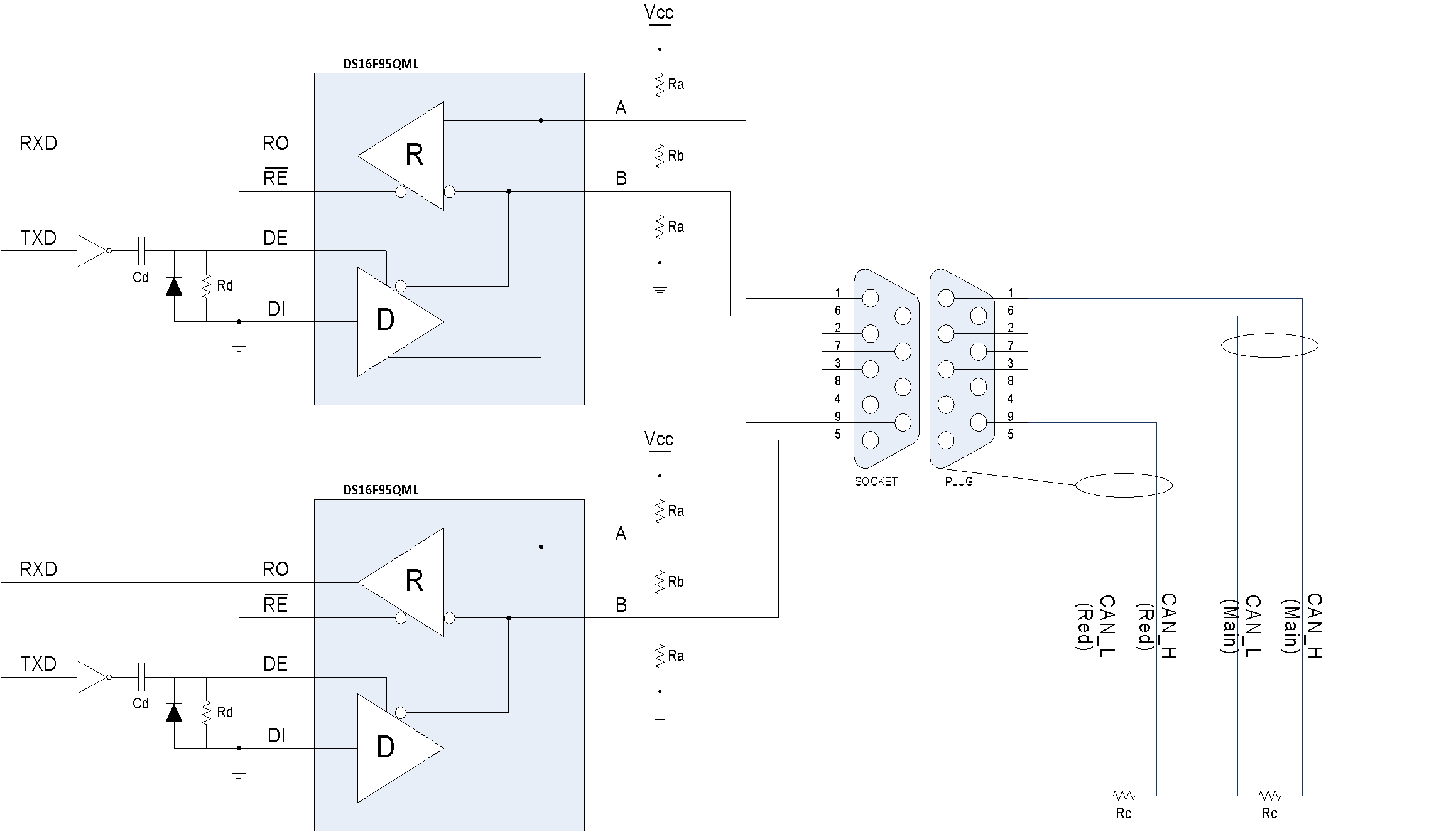 Figure: RS-485 CAN physical interface for OBC/Bus Master
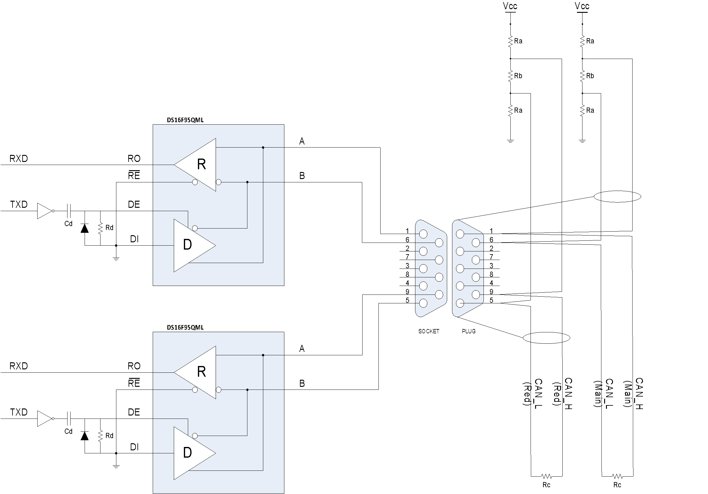 Figure: RS-485 CAN physical interface for nodes using single connector for redundant buses
 Figure: RS-485 CAN physical interface nodes using dual connector for redundant buses
The corresponding logic table for driver and receiver is Table A-1 and Table A-2.
Table: Logic Table, RS-485 Driver implementation
|
DRIVER
| |||
|
Driver input
|
Enable
|
Outputs
| |
|
DI |
DE |
A |
B |
|
H |
H |
H |
L |
|
L |
H |
L |
H |
|
H |
L |
Z |
Z |
|
L |
L |
Z |
Z |
Table: Logic Table, RS-485 Receiver implementation
|
RECEIVER
| ||
|
Differential input
|
Enable
|
Output
|
|
A –– B |

|
RO |
|

V |
L |
H |
|

V |
L |
L |
|
X |
H |
Z |
The required component values are summarized in Table A-3.
Table: Component item values
|
ITEM |
Value |
Unit |
Tolerance |
|
Ra |
590 |
|
1 % |
|
Rb |
130 |
|
1 % |
|
Rc |
121 |
|
1 % |
|
Rd |
10 |
K |
1 % |
|
Cd |
0.1 |
F |
15 % |
CAN Network Bus termination
The use of split termination is a concept that is growing in popularity because emission reduction and filtering of common-mode noise can be achieved very easily. termination is a modified standard termination in which the single 120 Ω resistor on each end of the bus is split into two 60 Ω resistors, with a bypass capacitor tied between the resistors and to ground. The two resistors are matched as closely as possible (see Figure A-5). By using a capacitor rated at 4,7nF high data rate is achievable see the TI application note SLOA101A [4]. This states that using this achieves a 1,1 Mbps 3db point for a low pass filter.
Due to project specific EMI/EMC requirements, the precise values of terminating resistors are calculated based on the particular CAN Network implementation, length, and topology. The cabling and signal reflection issues described in [11] and [12] are worth considering. In this scheme, a termination resistor implemented outside the equipment eases tuning of the actual resistor value in a particular system configuration up to a very late stage of development.
 Figure: (left) and standard (right) Termination schemes.
Bus management and redundancy
Selective bus access architecture
The selective bus access architecture implements a single CAN controller and interfaces the redundant CAN Network via two transceivers as illustrated in Figure A-6. A bus selection mechanism is implemented between the CAN controller and the transceivers allowing the application to select the bus to be used for communication. This architecture allows communication on only one of the two busses at a time.
Nodes implementing the selective bus access architecture are not capable of monitoring both busses simultaneously. Therefore, the protocol allows nodes to toggle between the nominal and redundant bus when searching for the Heartbeat of the Redundancy Master.
 Figure: Selective bus access architecture
Parallel bus access architecture
The parallel bus access architecture interfaces a redundant CAN Network through a pair of CAN controllers as illustrated in Figure A-7. This implies that each CAN Network is fully and independently accessible via a separate CAN controller. The detailed mechanisms for communication on the two busses are application specific and out of scope for this standard.
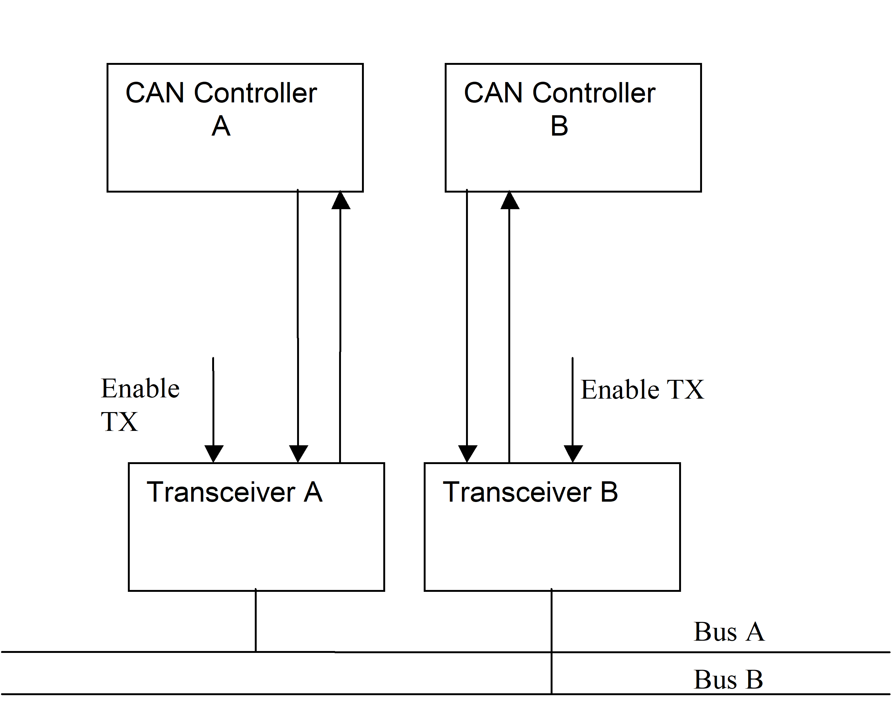 Figure: Parallel bus access architecture
Bibliography
ECSS-S-ST-00 - ECSS system - Description, implementation and general requirementsTELECOMMUNICATION STANDARDIZATION SECTOR OF ITU – X.200 (07/94) – Data networks and open systems communications, open systems interconnection – Model and NotationController Area Network (CAN), CAN Specification 2.0B, Robert Bosch GmbHTI Application Report SLOA101A – August 2002 – Revised July 2008 - Introduction to the Controller Area Network (CAN) - Steve Corrigan TI Application Report SLLA270 – January 2008 - Controller Area Network Physical Layer Requirements - Steve CorriganTI Application Report SLLA166 – May 2004 - The RS-485 unit load and maximum number of bus connections, by Kevin Gingerich (Email: k-gingerich@ti.com)Physical Layer Recommendations for CAN Network in Heavy Vehicles, Society of Automotive and Aerospace Engineers: SAE J2284Philips Semiconductor Application Note, CAN Network Timing: Philips AN4781NGFault Confinement Mechanisms on CAN: Analysis and Improvements - Bruno Gaujal and Nicolas Navet - IEEE TRANSACTIONS ON VEHICULAR TECHNOLOGY, VOL. 54, NO. 3, MAY 2005CANopen Cabling and Connector Pin Assignment: CiA Draft Recommendation DR-303-1 - Version 1.3 - 30 December 2004CAN Wiring – Notes on the wiring of CAN-Bus Systems and Cable Selection, Version 3.4, ESD Electronic System Design Gmbh, Hannover Cia99Paper - The Configuration of the CAN Bit Timing - 6th International CAN Conference 2nd to 4th November, () - Florian Hartwich, Armin Bassemir - Robert Bosch GmbHCAN Wiring – Philips Application Note AN96116 for the PCA82C250/1 CAN TransceiverGuidelines for Proper Wiring of an RS-485 (TIA/EIA-485-A) Network (APPLICATION NOTE 763 – MAXIM)RS-485: Passive failsafe for an idle bus – Texas Instruments Analog Application journal 1Q2009Bus isolation – Analog Devices AN-770 - APPLICATION NOTE: iCoupler® Isolation in busCAN Network Applications by Ronn Kliger and Sean ClarkK.W. Tindell , H. Hansson and A.J. Wellings, Analysing Real-Time Communications: Controller Area Network (CAN), Real-Time Systems Symposium, 1994., Proceedings pp. 256 - 263, 1994K. G. Shin, Real-time communications in a computer-controlled work-cell. IEEE Transactions on Robotics and Automation, Vol. 7 pp. 105 - 113, Feb. 1991K. M. Zuberi, and K.G Shin, Scheduling Messages on Controller Area Network for Real-Time CIM Applications, IEEE Transactions on Robotics and Automation, Vol. 13, No. 2, pp. 310 - 314, April. 1997.G. Cena and H. Valenzano, An improved CAN fieldbus for industrial applications, IEEE Transactions on Industrial Electronics, 1997, 44 (4), pp. 553 - 564S.H. Hong, Scheduling algorithm of data sampling times in the integrated communication and control system, IEEE\ Transactions on Control System Technology, 3 (2), 1995 pp. 225 - 230K. Tindell, Calculating Controller Area (CAN) message response times, Contr. Eng. Practice, Vol. 3, no. 8. pp. 1163-1169, 1995N. Navet and Y.-Q. Song ,Design of reliable real-time applications distributed over CAN (Controller Area Network) (INCOM'98 - IFAC) Int. Symp. On Information Control in Manufacturing, pp. 391 -396, 1998R. Rudiger, Evaluating the temporal behavior of CAN based systems by means of a cost functional Proc. 5th international CAN Conference '98, pp. 10.09-10.26, San Jose, CA, USA, 3-5 November 1998J-A Yung, S-W. Nam, K-W. Kim, S. Lee, M.H. Lee. J.M. Lee and J.H. Kim, Performance Evaluation of Multiplexing Protocols, International Congress and Exposition, . Feb. 23-26, 1998. SAE paper reference number 981105CiA 303-1 V1.8.0: CANopen recommendation - Part 1: Cabling and connector pin assignmentCANopen Framework for CANopen Managers and Programmable CANopen Devices. CiA Draft Standard Proposal 302 Version 3.3.0CANopen Electronic datasheet – Part 1: General definitions and electronic data sheet specification, CiA-306-1, CiACANopen Electronic datasheet – Part 3: Network variable handling and tool integration, CiA-306-3, CiACANopen device description – XML schema definition, CiA-311, CiAEtschberger, K.: CAN-based Higher Layer Protocols and Profiles; Proceedings of the 4th International CAN Conference; CAN-in-Automation; ; 1997Etschberger, K.: Controller Area Network; IXXAT Press; 2001; ISBN 3-00-007376-00Lawrenz, W.: CAN System Engineering, from theory to practical applications; Springer-Verlag; 1997; ISBN 0-387-94939-9Barbosa, M.: CANopen Implementation; Research Studies Press ltd.; 2000; ISBN 0-86380-247-8Leen, G. and Heffernan, D.: Time-triggered Controller Area Network, IEEE Computing and Control Engineering Journal. Vol. 12, Issue 6, Dec. 2001, pp. 245 - 256.Tindell, K and Burns, A. “Guaranteed Message Latencies for Distributed Safety Critical Hard Real-Time Networks”, 1994Texas Instruments SNLS392D –JUNE 1998–REVISED APRIL 2013 DS16F95, DS36F95 EIA-485/EIA-422A Differential Bus Transceiver (Data sheet).