
Space product assurance
Wire wrapping of high-reliability electrical connections
Foreword
This Standard is one of the series of ECSS Standards intended to be applied together for the management, engineering and product assurance in space projects and applications. ECSS is a cooperative effort of the European Space Agency, national space agencies and European industry associations for the purpose of developing and maintaining common standards. Requirements in this Standard are defined in terms of what shall be accomplished, rather than in terms of how to organize and perform the necessary work. This allows existing organizational structures and methods to be applied where they are effective, and for the structures and methods to evolve as necessary without rewriting the standards.
This Standard has been prepared by the ECSS Executive Secretariat, endorsed by the Document and Discipline Focal points, and approved by the ECSS Technical Authority.
Disclaimer
ECSS does not provide any warranty whatsoever, whether expressed, implied, or statutory, including, but not limited to, any warranty of merchantability or fitness for a particular purpose or any warranty that the contents of the item are error-free. In no respect shall ECSS incur any liability for any damages, including, but not limited to, direct, indirect, special, or consequential damages arising out of, resulting from, or in any way connected to the use of this Standard, whether or not based upon warranty, business agreement, tort, or otherwise; whether or not injury was sustained by persons or property or otherwise; and whether or not loss was sustained from, or arose out of, the results of, the item, or any services that may be provided by ECSS.
Published by: ESA Requirements and Standards Division
ESTEC, ,
2200 AG Noordwijk
The
Copyright: 2008 © by the European Space Agency for the members of ECSS
Change log
|
ECSS-Q-70-30A
|
First issue
|
|
ECSS-Q-70-30B
|
Never issued
|
|
ECSS-Q-ST-70-30C
|
Second issue
|
Scope
This Standard specifies requirements for preparing and assembling parts to be joined by wire wrapping, as well as the selection, calibration, use and certification of wire wrapping tools.
The covered wirewrapped connections are illustrated in Figure 11.
This type of connection is similar to “Class A preferred” or “modified” connection detailed in MILSTD1130, and NASA NHB 5300.4(3H).
Only previously tested and qualified wirewrapped connections are covered by this Standard, which includes four wire sizes from 24 AWG to 30 AWG, and three terminal post sizes up to 1,78 mm maximum diagonal. A step-by step procedure is covered in the informative Annex A.
The use of heavier gauge wire and larger terminals is not generally prohibited, but it is considered unlikely that for such dimensions the method of wirewrapping would be chosen as the electrical interconnection technique. Instead it is assumed that wire larger than 24 AWG will be multi-stranded and terminated by soldering in conformance with ECSS-Q-ST-70-08, or by crimping in conformance with ECSS-Q-ST-70-26.
Training and certification requirements for operators and inspectors are defined in clause 5.6.7 and in ECSS-Q-ST-20.
With effect from the date of approval, this Standard announces the adoption of the external document on a restricted basis for use in the European Cooperation for Space Standardization (ECSS) system.
This standard may be tailored for the specific characteristic and constraints of a space project in conformance with ECSS-S-ST-00.
 Figure 11: Single wirewrapped connection to square terminal and reference corner
Normative references
The following normative documents contain provisions which, through reference in this text, constitute provisions of this ECSS Standard. For dated references, subsequent amendments to, or revisions of any of these publications do not apply. However, parties to agreements based on this ECSS Standard are encouraged to investigate the possibility of applying the most recent editions of the normative documents indicated below. For undated references the latest edition of the publication referred to applies.
|
ECSS-S-ST-00-01
|
ECSS system – Glossary of terms
|
|
ECSS-Q-ST-20
|
Space product assurance – Quality assurance
|
|
ECSS-Q-ST-70-02
|
Space product assurance – Thermal vacuum outgassing test for the screening of space materials
|
|
ECSS-Q-ST-70-38
|
Space product assurance – High-reliability soldering for surface-mount and mixed technology
|
|
ESSCC Generic specification 3903
|
Solid wires, electrical 350V, for wire wrapping
|
Terms, definitions and abbreviated terms
Terms defined in other standards
For the purpose of this Standard, the terms and definitions from ECSSSST0001 and ECSSQST-70-38 apply.
In particular from ECSS-Q-ST-70-38 the following term:
process identification document (PID)
The content of the PID is specified in ECSSQST70-38.
Terms specific to the present standard
a turn of wire
a wrap consisting of one complete single helical ring of wire wrapped 360 degrees around the terminal post, touching all four corners of the post.
For the purpose of counting turns, the number of times the wrapped wire passes and intercepts the reference edge of the terminal post after the first intercept of uninsulated wire and terminal post, constitutes the number of turns of uninsulated wire in the connection.
end tail
end of the last turn of wire on the terminal post which can extend in a tangential direction instead of resting against the post
gastight area
contact area between the terminal post and wire which excludes gas fumes
reference corner
corner of the terminal post at which the first turn of uninsulated wire contacts, and from which the number of turns of the wrapped wire are counted.
terminal post
post of square or rectangular section onto which the interconnection wire is wrapped.
wirewrapped connection
connection consisting of a helix of continuous, solid, non-insulated wire tightly wrapped around the terminal post to produce a mechanically and electrically stable connection.
- 1 The number of turns required will depend on the gauge of wire used.
- 2 All completed wraps have an additional minimum of 3/4 turn of the insulated wire that is in contact with at least three corners of the terminal post (see Figure 11).
Abbreviated terms
For the purpose of this Standard, the abbreviated terms from ECSS-S-ST-00-01 and the following apply:
|
Abbreviation
|
Meaning
|
|
AWG
|
American wire gauge
|
|
ETFE
|
ethylene-tetrafluorethylene (Tefzel)
|
|
NCR
|
nonconformance report
|
|
PFA
|
perfluoroalkoxy
|
|
PID
|
process identification document
|
|
PTFE
|
polytetrafluorethylene
|
|
PVDF
|
polyvinylidene fluoride (Kynar)
|
|
QA
|
quality assurance
|
|
RFA
|
request for approval
|
|
RH
|
relative humidity
|
Principles
The production of wire-wrapped connections is a relatively simple yet precision method of fusion. Its use for high reliability space conditions affords high skills of operators and inspectors as well as tooling and environmental controls to produce continued high level quality. The following principles are laid down in this Standard:
Each tool is certified for each wire to post configuration; regular calibration is mandatory.
All material, including wire and post, requires approval and rigorous inspection.
A well-defined and documented process control document (PID) to ensure consistency of production over extended periods.
Operators and inspectors need experience and regular training and certification.
Frequent inline inspection and testing of wire-wraps validate continued quality levels for the intended high reliability application.
Formal Quality Assurance and documentation will substantiate the achieved level of compliance to the requirements within this Standard.
It is important to perform the work taking into account health and safety regulations and in particular the national standards on this subject.
Requirements
Preparatory conditions
Hazards, health and safety precautions
Components, tools and controls shall be so located that personnel are not exposed to hazards such as electric shock, cutting edges, sharp points or toxic atmospheres.
Pneumatic airpowered wirewrapping tools shall be connected to a regulated, lubricated and filtered air supply, and disconnected when not in use.
Facilities
Facility cleanliness
The supplier shall provide for a work environment in conformance with the following:
Those requirements are in general met by using cleanrooms. It is not, however, mandatory to use a cleanroom.
- The areas in which wirewrapping is carried out are maintained in a neat orderly fashion, with no loose material that can cause contamination of the wirewrapped connection.
For example: Dirt, dust, oils or clipped wires.
- Furniture is kept to a minimum in the work areas and be arranged to allow easy and thorough cleaning of the floor.
- Working surfaces are covered with an easily cleaned hard top, or have a replaceable surface of clean, non-corrosive siliconefree paper.
- Tools used in the wirewrapping operation are clean.
For example: Excess lubricant is removed before wirewrapping starts.
Environmental conditions
The following environmental conditions at the wirewrapping workstations shall be established:
- controlled environment which limits entry of contamination;
- continuously controlled temperature and humidity as follows:
- room temperature: (22 ± 3) °C;
- relative humidity: (55 ± 10) %.
- no exposure to draughts;
- supply of fresh air through a filtering system to establish a positive pressure difference to adjacent rooms; the exhaust air is restricted to avoid turbulences.
Lighting requirements
Adequate illumination conditions of the wirewrapping workstations shall be implemented as follows:
- light intensity with a minimum of 1080 lux on the work surface.
- at least 90 % of the work area are shadowless and without severe reflections.
Tools and equipment
Cutting tool
The selected cutting tool shall cut the conductor wire without causing flattening of the wire.
Any tool not conforming with requirement 5.1.3.1a shall be removed from the work area.
Insulation strippers
To avoid damage to the conductor, stripping devices, in particular thermal and precision cutting devices, manual or automatic power-driven shall
- provide protection of the conductor wire;
- avoid wire stretching by use of mechanical strippers;
- avoid that the conductor is twisted, ringed, nicked, cut or scored by the stripping operation. Any tool not conforming with requirement 5.1.3.2a shall be removed from the work area.
Wirewrapping tools
Wrapping tools together with specific rotary bit and stationary sleeve shall be
- assigned to each wire gauge and terminal combination in use,
- marked to show the size, for which it is calibrated. The following power-driven wirewrapping tools shall be used:
- electrical tool with mains supply,
- pneumatic tool, supplied with regulated, lubricated and filtered air.
Figure A-1 shows examples of power-driven wire-wrapping tools.
The power-driven wirewrapping tools should be fitted with a “back-force” device to prevent overwrapping defect.
Handpowered or batterypowered wrapping tools shall not be used.
Refer to the tool manufacturer for selection of bit and sleeve for each wire/terminal post diagonal combination.
The tool and associated accessories shall be checked for cleanliness and general satisfactory condition under up to ×10 magnification as follows:
- The extremity of the bit is perfectly clean and smooth without blockages or faults.
- The sleeve does not have any sharp blockage in its neck, and manual check ensures that the bit runs perfectly in the sleeve, without any hard or rough points of contact.
The wirewrapping tool shall not nick, ring, gouge, or scrape conductors, or damage the terminal post in any way during its operation.
Any tool not conforming with the requirements 5.1.3.3a to 5.1.3.3f shall be removed from the work-station for repair or replacement.
Unwrapping tools
The supplier shall provide an unwrapping tool compatible with the terminal post diagonal which does not nick, ring, gouge, scrape or damage the terminal post in any way.
- 1 Figure A-3 shows examples of unwrapping tools.
- 2 Wrapped connections can be detached from their terminal posts, when necessary, by means of special unwrapping tools.
- 3 Manual unwrapping tools are preferred. They are short tubular tools having an external spiral groove and handle.
- 4 A “lefthand” unwrapping tool is required to unwrap a “righthand” wrap connection (clockwise wire rotation from base to top of terminal), or vice versa for a “lefthand” wrap connection.
Damaged tools shall be removed from the work-station for repair or replacement.
Test monitoring equipment
Equipment for performance testing shall have the following characteristics:
|
1.
|
Connection resistance
|
0 A - 10 A ammeter with current source
|
|
2.
|
Stripping force
|
Tensile testing machine
|
|
3.
|
Visual inspection
|
Binocular microscope, magnification × 7 minimum, with suitable light source
|
|
4.
|
Microsectioning:
|
Metallurgical microscope, magnification up to × 400.
|
The equipment shall be capable of monitoring in the following range of environmental conditions:
|
1. |
Temperature |
15° C to 30° C, accurate to 1 °C |
|
2. |
Humidity |
RH 40 % to 70 %, accurate to 1 % RH |
Configuration of process and workpiece
Materials, tools and techniques, which are planned to be used shall be reviewed with respect to design needs, to ensure conformance to customer requirements and as a means of identifying any pending process qualification.
The review shall cover each separate manufacturing step including the dimensions and metallurgical properties of the terminal post and wire.
Aim is that materials are proven to be acceptable for the manufacture of wirewrapped connections.
The choice of functional tools, particularly the type of powerdriven wirewrapping tool and associated rotary wrapping bit and stationary sleeve shall be demonstrated to be adequate to the wrapping process.
The quality of a wrapped connection depends largely on the maintenance and adjusting of the cutting, stripping and wrapping tools.
The supplier shall generate a dedicated process identification document (PID) in conformance with the requirements in ECSS-Q-ST-70-38, listing all used tools, material and the adjustment of the tools.
Work shall be managed and organized such that tool bits and sleeves cannot be interchanged.
During handling and transportation, wrapped joints and their wires shall not suffer from any mechanical or environmental constraint, likely to cause deterioration.
Wire-wrap process certification
Initial certification of each wirewrap combination
The capability of the wirewrap tool shall be established to produce acceptable wirewrap connections for each combination of tool with correct bit and sleeve, wire gauge and terminal post.
30 sample wrap connections shall be prepared with a calibrated tool.
The certification test sequence shall be as follows:
- Samples 1 to 30 Workmanship (see clause 5.5.1)
- Samples 1 to 30 Connection resistance (see clause 5.4.4)
- Samples 1 to 10 Stripping force (see clause 5.4.2)
- Samples 11 to 20 Unwrapping test (see clause 5.4.3)
- Samples 21 to 26 Gastightness test (see clause 5.4.5)
- Samples 27 to 30 Metallography (see clause 5.4.6)
The successful completion of all above tests will authorize spacecraft wire wrapping to commence for the wrap combination.
Recertification of each wirewrap combination
Re-certification shall be carried out after the following occurrences:
- When production wraps fail to conform with the requirements of the daily processcontrol tests specified in clause 5.6.8.3.
- At every 10 000 wirewrap connections in a continuous programme.
- If production is interrupted for a period in excess of 12 months.
This is supposed to ensure reliability of the joint, as the wire and terminals may degrade during storage.
The recertification test sequence shall be a repeat of the above clause 5.1.5.1, 30 sample wrap connections being prepared with a calibrated tool.
Requirements for new combinations of wire-wrap
General
Verification tests shall be conducted to establish confidence in the reliability of wirewrap combinations not detailed in Table 51.
The combination shall be considered verified following successful completion of process certification tests in conformance with requirements of clause 5.1.5 on 30 sample wraps before, and a further 30 sample wraps after temperature cycling and vibration testing detailed below.
Temperature cycling
The test samples shall undergo 200 temperature cycles in a chamber from room temperature to 55 °C, to +100 °C and back to room temperature (22 ± 3)°C at a rate not exceeding 10 °C per minute.
Soak time at each temperature extreme shall be 15 minutes, such that the duration of each cycle averaging one hour.
These conditions can be modified to conform with the particular environmental qualification conditions for the assembly being verified.
Vibration
After completion of the temperature cycling, the test samples shall be subjected to vibration.
Test levels, frequencies and durations shall be agreed with the customer.
Documentation
The supplier shall document all conditions and operating procedures in the PID format, see clause 5.1.4.
The supplier shall document all verification results in the RFA format, subject to customer approval.
Material selection
Wire
General
Wire used for wrapped connections shall conform with ESCC Generic Specification 3903.
Other approved national wire specification intended for wirewrapping may be agreed with the customer.
The insulation type and wire finish shall be presented for approval by the customer.
Conductor
The wire shall be a single solid round conductor.
Stranded conductors shall not be used.
Bending, stretching, or other cold working of the wire shall be avoided to preclude damage to the base material or plating.
The conductor diameter shall be within the range 0,25 mm to 0,51 mm nominal (30 AWG to 24 AWG), and from the following material:
- softannealed, highconductivity copper having an elongation at fracture of not less than 15 %, for wire gauges 24 AWG and 26 AWG, or
- highstrength, highconductivity copper alloy with less than 2 % strengthening elements, having an elongation at fracture of not less than 7 %, for wire gauges 28 AWG and 30 AWG.
These materials are suitable for use within the temperature range -55 °C to +100 °C.
Annealed copper shall not be continually operated for long periods above 90 °C, owing to the likelihood that excessive wire stress relaxation affects the reliability of the wrap connection.
The conductor shall be finished with smooth and uniform silver-plating.
The preferred average thickness of silver plating is 0,002 mm.
At the time of making the connection, the silver finish shall be free of tarnish.
Wire insulation
The insulation shall consist of flexible polymer materials with low out-gassing properties, in conformance with ECSSQST-7002.
Recommended insulation materials include ETFE (Tefzel), PFA (Perfluoroalkoxy), PVDF (Kynar), and Kapton polyimide over extruded PTFE.
The insulation shall
- not be bonded to the conductor;
- be capable of being readily stripped from the conductor without change to the physical characteristics of the wire;
- be removed just prior to wrapping;
- if precut and stripped, the area be protected prior to use under dry nitrogen.
There shall be no exposure of the conductor base material after insulation stripping.
The conductor and its insulation shall be concentric such that the minimum insulation wall thickness is not less than 70 % of the maximum wall thickness.
The insulation shall have a wall thickness matching mechanical and electrical stability, which is generally in excess of 35 % of the conductor diameter.
Insulation wall thickness varies between wire manufacturers; smaller values need substantiation before acceptance.
The compatibility between the outer diameter of the insulated wire and the tool bit shall be established.
The wire strip length shall be controlled to give the correct number of turns of bare wire onto the terminal post, as specified in Table 52.
Terminal post
Material and plating
The material shall be selected from the following list:
- grades of copper or nickel alloys, such as copperzinc, phosphor bronze,
- coppernickelzinc,
- berylliumcopper, nickelcopper (Monel), and
- nickelclad copper (Kulgrid).
The alloy hardness shall be within the range from 150 Vickers to 220 Vickers hardness.
Terminal posts shall be finished with 0,001 mm to 0,003 mm thickness of gold plating over 0,001 mm minimum average thickness of copper or nickel under-plating.
Silver under-plating shall not be used.
The surface finish shall be smooth and uniform.
Dimensions
The length of terminal post projecting from the mounting fixture shall accommodate the required number of wrapped connections.
The number of wraps shall not exceed three per terminal.
The minimum wrapping length for each wire gauge for one, two and three wrapped connections on each terminal is shown in Figure 51.
Terminal posts shall have a solid cross section.
- 1 Geometry and dimensions for each approved terminal size are shown in Figure 52. Terminal posts with a square cross section are preferred. The rectangular (0,76 mm × 1,52 mm) post is included to achieve better terminal packing density if required for 24 AWG and 26 AWG wire, where the more robust terminal is necessary.
- 2 Referring to Figure 52, note that the tolerance on diagonal C is more important than on A and B dimensions, as posts are accommodated by round holes in the tool bit.
The terminal posts shall be straight and free from bends and bows, which can restrict the free entry of the post into the hole of the tool bit.
Bent terminals shall be rejected.
Tip configurations shall be in conformance with the following: - The tip of the terminal post terminates in a radius or bevel to facilitate insertion into the wrapping tool.
- Use flat apex of the bevel if the tip of the post terminates in a bevel,
- The side of the flat does not exceed 0,38 mm on the 0,64 mm square post geometry, or 0,50 mm on the 1,14 mm square post and on the 0,76 mm × 1,52 mm rectangular posts.
Stability
Terminal posts shall be durable enough to withstand being unwrapped and rewrapped and still conform with the test requirements in clause 5.4.
Annex A.2 describes the rework procedure.
Terminal posts shall be mounted and not capable of rotating during the wrapping operation.
Boards or connectors with terminal posts for wrapping shall be handled carefully in order to avoid damaging the sharp corners of the posts.
A practical means for avoid damaging is given in Annex A.1.
|
Number of wrapped connections
|
Minimum wrapping length (mm)
| |||
|
30 AWG
|
28 AWG
|
26 AWG
|
24 AWG
| |
|
1
|
4,7
|
5,6
|
5,8
|
6,6
|
|
2
|
8,2
|
9,9
|
10,2
|
11,9
|
|
3
|
11,6
|
14,2
|
14,7
|
17,2
|
Figure 51: Minimum wrapping length on terminal post for each wire gauge
|
Dimension (mm)
|
Parallelism (mm/mm)
| ||
|
A
|
B
|
C
| |
|
0,64 nominal
|
0,64 nominal
|
0,90 nominal
|
0,005
|
|
1,14 nominal
|
1,14 nominal
|
1,68 nominal
|
0,005
|
|
0,76 nominal
|
1,52 nominal
|
1,78 nominal
|
0,005
|
Figure 52: Terminal post dimensions over minimum wrapping length for each terminal size
Wire to terminal post combinations
Combinations of wire sizes to terminal post size shall be in conformance with Table 51.
New combinations of wire and terminal post sizes shall be verified in conformance with requirements from clause 5.1.6.
Table 51: Wire size to terminal post combinations
|
Terminal post size (nominal)
|
Wire size AWG
| |||
|
30
|
28
|
26
|
24
| |
|
0,64 mm 0,64 mm
|
yes
|
yes
|
yes
|
no
|
|
1,14 mm 1,14 mm
|
no
|
no
|
yes
|
yes
|
|
0,76 mm 1,52 mm
|
no
|
no
|
yes
|
Yes
|
Wire-wrap operation
Preparation for wirewrapping
Insulation shall be removed by approved tools referred to in clause 5.1.3.2.
Stripping shall not expose conductor base metal.
After insulation removal, the remaining conductor insulation shall not exhibit any damage such as nicks, cuts, crushing or charring.
Conductors with damaged insulation shall not be used.
Slight discoloration from thermal stripping is acceptable.
The stripped conductor shall not be nicked, cut, scraped or otherwise damaged.
Burnishing of the wire is allowed, provided the conductor base metal is not exposed.
Conductors, which have been reduced in cross section, shall not be used.
Damaged wires shall not be used.
Process and criteria
General
Wirewrapped connections shall be produced in conformance with the approved process identification document (PID) (as specified in requirement 5.1.4d) using an approved tool type detailed in clause 5.1.3.
The step-by-step procedure is shown and illustrated in Annex A.1.
Spacing between adjacent turns, the sum of all spaces within one wrap, and the distances for positioning wraps on the terminal post shall be as detailed in Figure 53.
This also gives the dimension limits for the minimum number of turns required.
In case of necessary rework, the wrapped wire shall be uncoiled using an approved hand tool (see clause 5.1.3.4), to preserve the corners of the terminal post.
The tool shall be clean and without any blockages on the outside.
Details of the procedure and acceptable number of reworks are given in Annex A.2.
Solder connections shall not be added to terminal posts supporting wirewrap connections.
Usage of wrap levels
The distribution of the wraps on the same post shall depend on the level of wiring.
Terminal post length is designed to receive a maximum of three levels of wrap joint.
The first connection onto the terminal shall be at level Zl.
- 1 Levels Zl and Z2 (see Figure 53) are generally used for pointtopoint interconnection.
- 2 Level Z3 is generally reserved for modification, doubling of wire gauge between two points.
Wraps that extend above level Z3 onto the bevelled apex portion of the post shall be removed and replaced.
Lower wraps may extend into the Z3 level if it is open and not reserved for future wiring.
Wirewrap level and wire routing shall be identified on the engineering drawing.
 Figure 53: Position and regularity of wrap connection
Number of turns on terminal post
The number of turns of uninsulated conductor shall be counted from the reference corner.
The reference corner is the first corner of contact if the insulation stops before the central axis of the post, or the second corner if the insulation crosses the central axis of the post (see Figure 11).
There shall be no overlap of turns to the last locked point.
- 1 The last locked point is the last terminal post corner.
The end tail shall not extend away from the outside diameter of the conductor on the post by more than the diameter of the conductor.
The minimum number of turns of uninsulated conductor and insulated wire to be wrapped for each wire gauge shall be as specified in Table 52.
This ensures that the gastight area of the connection results in a larger cross section than that of the wire used.
Table 52: Minimum number of wire turns on terminal post
|
Wire size
|
Minimum number of turns
| |
|
AWG
|
Nominal diameter (mm)
| |
|
30
|
0,25
|
7 + ¾
|
|
28
|
0,32
|
7 + ¾
|
|
26
|
0,40
|
6 + ¾
|
|
24
|
0,51
|
5 + ¾
|
Wire routing
Wire routing around and between terminal posts shall be such that wires do not press against the corners of posts with sufficient force to cut the insulation.
Wire with insulation, which has been cut, shall be removed and replaced.
Wires can be rerouted to correct a tight wire condition or relieve a wire density problem, provided the wrap connection is not disturbed.
Disturbed joints shall be rejected and replaced.
Wire shall not be routed above the terminal posts.
Long lengths of interconnect wire shall be bonded or tied down to the module at 50 mm to 75 mm intervals to reduce resonance in the wire during vibration.
Rework
When replacement connections are made in conformance with requirement 5.3.2.1c, the wire routing shall follow the original route.
If only two levels of wrap on the terminal post are occupied, the Z3 level shall be used as an alternative to rework the lower level wrap joints.
A wirewrap rework log shall be established and maintained during manufacture and test for each flight assembly.
The log shall contain the positions of the reworked wraps and the number of reworks on every terminal post.
Test methods
General
The following test methods shall be used to verify the quality of wirewrap connections:
- Tool calibration: in conformance with requirements in clause 5.6.5.
- Wirewrap process certification: in conformance with requirements in clause 5.1.5.
- Process control: in conformance with requirements in clause 5.6.8.3.
The number of wire-wraps to be tested, together with the test methods, is detailed in the following clauses.
Stripping force
Stripping force test shall be performed to determine adequate tightness of the wire around the terminal post.
A completed wirewrap connection with the minimum number of turns listed in Table 52 shall conform with the minimum stripping force specified in Table 53.
The minimum stripping force, see Table 53, shall be measured and recorded after the force has been applied and before the wrapped conductor has been moved one wire diameter from its original position.
Each result shall be greater than the acceptable minimum stripping force specified in Table 53.
The samples shall be tested using a test fixture.
An example of a text fixture is illustrated in Figure A-5.
There shall be no binding or wedging between the jaws and the terminal post.
The clearance between the jaws and the terminal post shall not exceed 70 % of the conductor diameter.
The jaws shall engage at 90° to the axis of the terminal post, creating a flat surface contact with the wire at the base of the wrap connection.
When testing wraps onto the rectangular (0,76 mm × 1,52 mm) terminal post, the jaws of the hook shall engage along the 1,52 mm edge dimension.
The test fixture shall be placed in a tensile testing machine, whose calibration is accurate to ±0,2 N, and the axial load applied at a crosshead speed of 1 mm/min to 50 mm/min.
Table 53: Minimum stripping force
|
Wire size
|
Minimum stripping force (Newton)
| ||
|
AWG
|
Nominal diameter (mm)
|
0,64 mm square terminal post
|
1,14 mm square and 0,76 mm 1,52 mm terminal posts
|
|
30
|
0,25
|
20,0
|
-
|
|
28
|
0,32
|
25,0
|
-
|
|
26
|
0,40
|
25,0
|
35,0
|
|
24
|
0,51
|
-
|
40,0
|
Unwrapping test
The supplier shall perform unwrapping tests which are complementary to the stripping force test to assess the cold working behaviour of the wrapped wire, together with the penetration of the terminal post corners into the wire.
The test ensures against an overtight wrap. Details of the procedure are given in Annex A.3.1
The wire on the terminal post shall be capable of being unwrapped without conductor breakage.
The unwrapped wire cannot be straight; waves and permanent deformation are allowed.
Connection resistance
The connection resistance of a single wrap joint shall be determined at the current specified in Table 54.
Figure A-6 shows how to determine the connection resistance.
The connection resistance shall not exceed 2 mΩ, calculated from:
Equation connection resistance![]()
The voltage drop shall be measured between the first turn of uninsulated conductor, and the terminal post, by using probe contacts suitable to the wire size.
The probe to the terminal post shall make contact at the end of the wrap joint without touching the wire.
Table 54: Test current for connection resistance
|
Wire size
|
Test current to be used to determine connection resistance (A)
| |
|
AWG
|
Nominal Diameter (mm)
| |
|
30
|
0,25
|
1,0
|
|
28
|
0,32
|
2,0
|
|
26
|
0,40
|
2,4
|
|
24
|
0,51
|
2,4
|
Gastightness test
The test shall be performed to demonstrate the integrity of the wirewrap connection by confirming the mechanical “gastight” interconnection between conductor and terminal post corners.
Details of the procedure are given in Annex A.3.2
The wrapped connection shall show evidence on every turn, except the first and last, of a gastight surface equal to or greater than 75 % of the corners of the terminal post in contact with the bare conductor.
This means, either 3 or 4 terminal post corners per turn of bare conductor are gastight.
Metallography
Metallographic tests shall be performed during process certification.
The microsection shall be prepared to reveal:
- confirmation of plating thickness, uniformity and adhesion onto wire and terminal post, and their materials;
- any damage to corner of terminal post due to the wirewrap;
- extent of the gastight mechanical joint, and indentation of the wire, which, if excessive can lead to failure of the unwrapping test;
- terminal post corner indentation into pure copper wire is greater than into copper alloy wire.
- 1 Metallography can also be used during preliminary evaluation of the conductor/terminal post interface for new combinations, see clause 5.1.6.
- 2 A typical satisfactory wrap crosssection for copper alloy wire wrapped onto a 0,64 mm square terminal post is illustrated in Figure A-7.
The joint to be sectioned shall be mounted in a low exotherm resin capable of being moulded without the application of external pressure.
The joint shall be oriented so that the wire is perpendicular to the polishing surface.
The specimen shall be ground with the aid of grades of silicon carbide papers in order to expose the midsection of the joint.
This section shall then be polished with successively finer grades of diamond paste down to 1 µm.
To aid microscopic examination, the polished section shall be lightly etched with a suitable chemical reagent specific to the composition of the materials being wrapped.
Records of tests
Records of all test results identified with individual test samples shall be maintained.
Individual test samples failing to conform with the minimum test requirements of clause 5.5.3 shall be recorded on the project NCR format.
Failure of not conform with test requirements shall be cause for rejection of all wraps made after the last successful test sequence.
The failed wirewrap combination shall be submitted to process certification tests, detailed in clause 5.1.5, to determine cause of the process failure.
Workmanship and acceptance criteria
Visual inspection
The operator shall visually examine wire and terminal posts before assembly for cleanliness, absence of oil films and freedom from tarnish or corrosion.
The operator shall carry out visual inspection with the aid of a binocular microscope having an initial magnification of 7 of the following parts:
- terminal posts,
- wire,
- the form and position of the wrap connection, and
- the routing of wire.
Further examination of suspect defects shall be made at higher magnifications up to 30.
Probing shall not be performed with any object which can physically disturb the wire-wrap connection.
The operator shall confirm that during visual inspection, the following criteria are met. - The silver plating on the conductor has no nicks or scratches exposing the base material (refer also to the requirements of clause 5.2.1).
- The terminal posts conform with the requirements of clause 5.2.2.
- Wirewrap connections are clean and free of foreign material.
- There is no evidence that the connection has been disturbed after manufacture.
- The wire insulation makes captive contact with at least three corners of the terminal.
- There is no overlapping between two adjacent connections on the same terminal post (see Figure 54, case B).
- Uniformity and correct positioning of the wrap on the terminal post conform with the requirements of clause 5.3.2.1 and Figure 53.
- The number of turns of conductor conforms to the requirements of clause 5.3.3 and Table 52.
- The end tail conforms to the requirements of clause 5.3.3 (see Figure 54, case E).
- No overlapping turns are present within the wrap joint (see Figure 54, case F).
- The conductor is tightly wrapped onto the terminal post.
- The maximum spacing between adjacent turns does not exceed 1/2 the diameter of the uninsulated conductor, and, excluding first and last turns, the sum of all gaps does not exceed the conductor diameter (see Figure 53).
- The insulated wire is routed in a manner which does not tend to unwrap the wire on the terminal post.
Replacement and rework
Defective wire and posts shall be replaced.
Connections with insufficient insulation in contact with the terminal post shall be reworked in conformance with requirements in clause 5.3.5 (see Figure 54, case A).
In case of overlapping use one of the following options:
Rework the top connection;
Rework both connections if the top connection overlaps more than one turn of the lower connection.
Wire wrapped too high on the terminal post shall be reworked (see Figure 54, case C).
Wraps with insufficient conductor turns shall be reworked (see Figure 54, case D).
“Spiral” and “Open” wrap conditions, illustrated in Figure 54, case G and Figure 54, case H respectively, shall be reworked.
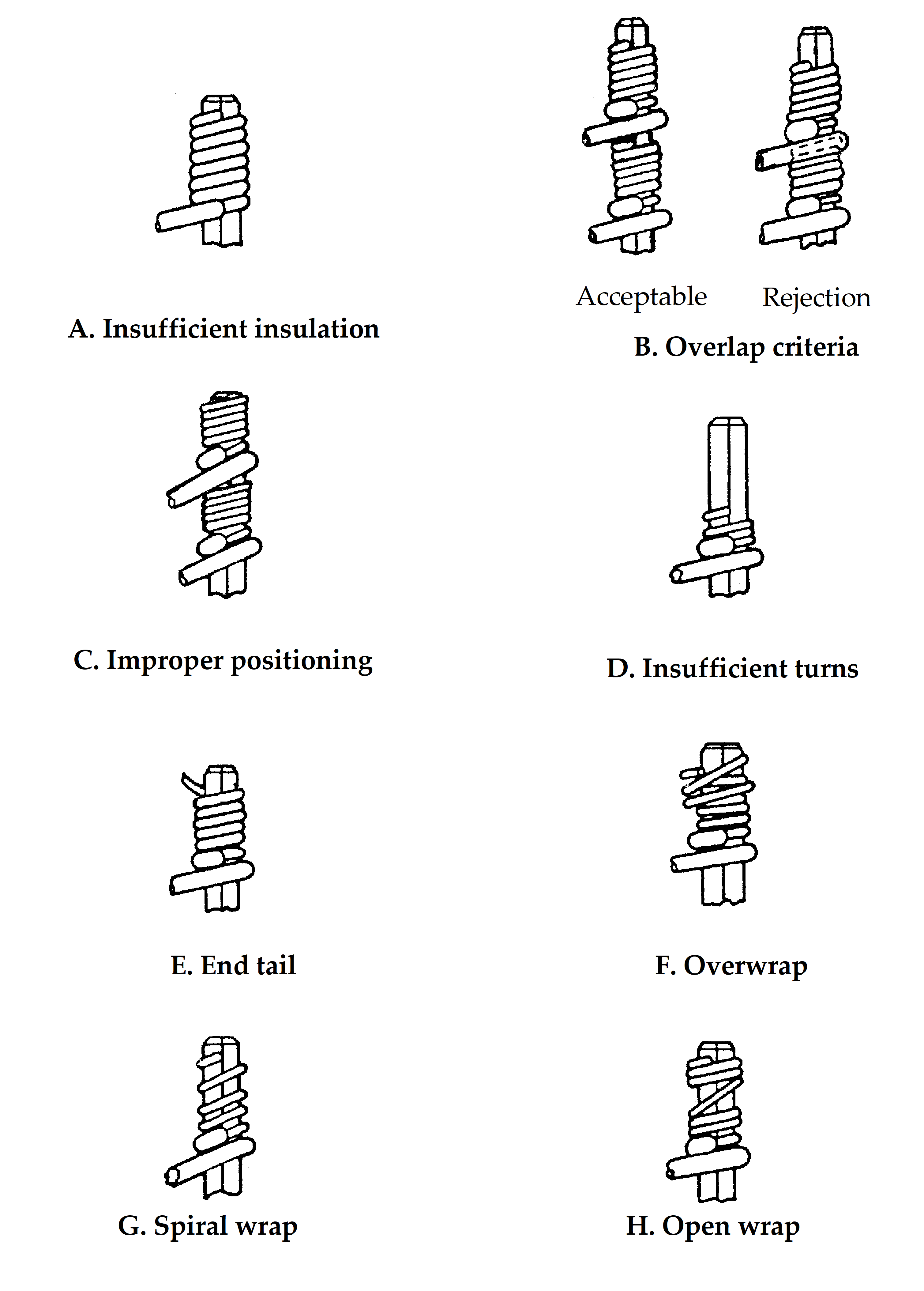 Figure 54: Wirewrap rejection criteria which require reworking of the connection
Performance tests
General
Wirewrap samples shall be performance tested as specified in requirements in clause 5.4.
After a sample fails to conform with the acceptance criteria listed in clauses 5.5.1 and 5.6.8.3, production wraps produced by the operator concerned shall be rejected subsequent to his last successful performance sampling.
Stripping force test
The measured stripping force shall exceed the minimum values listed in Table 53.
Unwrapping test
The unwrapped conductor shall not be broken.
Indents, waves and permanent deformation along the length of the unwrapped conductor are permitted.
Connection resistance test
The connection resistance of a single wrap joint shall not exceed 2 m.
Gastightness test
Unattacked bright gastight areas shall occupy 75 % or greater of the corners of the terminal post in contact with the bare conductor (except for the first and last turns).
Metallography
Microsections shall be examined in the lightly etched condition to reveal the extent of the gastight joint between conductor and terminal post, and for confirmation of the quality and materials of conductor and terminal post.
Quality assurance
General
The supplier shall conform with the quality assurance requirements defined in ECSSQST-20.
Specific quality assurance activities shall be as given in Figure 55.
Traceability
Traceability shall be maintained throughout the process from incoming inspection to final test, including details of test equipment, tools and personnel employed in performing the task.
Data
Quality records and logbooks shall be retained for at least ten years or in conformance with project contract requirements, and contain as a minimum the following:
- The asbuilt and test configuration list including waiver and deviation summary.
- Nonconformance reports and corrective actions.
- Copy of the visual inspection and performance test results with reference to the relevant procedure, personnel and tools utilized, including the records of daily testing, see clause 5.6.8.3.
- Records of the training, testing and certification status of wirewrapping operators (see clause 5.6.7).
Nonconformance
The supplier shall disposition any nonconformance, which is observed in respect of the process in conformance with the quality assurance requirements of ECSSQST20.
Failure of a wire wrapping tool conform with any requirements specified in clauses 5.1.3, 5.1.5, 5.6.5 and 5.6.8 shall require rejection of all wraps made by that tool since it was last tested successfully for acceptance.
Figure 55: Guide to quality assurance during wire wrapping
Calibration
Initial tool calibration shall be carried out to confirm that a new or repaired tool (with appropriate bit and sleeve) is working correctly.
Only calibrated tools shall be authorized for use.
Before calibration it shall be confirmed that the tool conforms with the requirements of clause 5.1.3.3.
30 sample wrap connections between the selected wire and terminal post referred to in clause 5.2.2.4, shall be prepared for each tool.
The calibration test sequence shall be as follows:
- Sample 1 to 30 Workmanship (see clause 5.5.1)
- Sample 1 to 15 Stripping force (see clause 5.4.2)
- Sample 16 to 30 Unwrapping test (see clause 5.4.3)
Recalibration shall be carried out at intervals of 12 months or whenever the tool is repaired.
A tool calibration record shall be kept with the tool.
Tool/wire/terminal certification shall be carried out using the calibrated tool (see clause 5.1.5).
Test monitoring equipment shall be periodically calibrated as detailed in clause 5.1.3.5, and calibration records be kept.
Any suspected or actual equipment failures shall be recorded as a project nonconformance report so that previous results can be examined to ascertain whether or not reinspection and retesting is required.
The customer shall be notified of the nonconformance details.
Workmanship standards
Visual standards consisting of satisfactory work samples or visual aids which clearly illustrate the quality characteristics of wirewrap connections shall be prepared and available to each operator and inspector.
The illustrations presented in Figure 53 and Figure 54, supplemented by photographic or physical material, shall be included as examples.
Operator and inspector training and certification
Trained and competent personnel shall be employed for wirewrapping operations and inspection.
A training programme shall be developed, maintained and implemented to provide for excellence of workmanship and personnel skill, careful and safe operations, and improvement of the quality of wrapped joints.
Trained personnel shall be certified.
The certification of personnel shall be based upon objective evidence of wire wrap quality, resulting from test and inspection of the wrap joints.
Re-certification of personnel shall apply in cases of repeatedly unacceptable quality levels and changes in wirewrapping techniques, parameters or required skills.
Records shall be maintained of the training and certification status of operators and inspection personnel.
All training and certification shall be performed at a school authorized by the customer.
Inspections
Pre-wrap inspection
Before the stripped wire is inserted into the wrap tool wire feed slot, the stripped conductor and wire insulation shall be examined.
The acceptance criteria are specified in clause 5.3.1.
Inspection shall verify that wire size and type and the terminal posts are as specified on the drawing or control document.
Post-wrap inspection
The inspection shall be carried out with the aid of a binocular microscope in conformance with requirements of clause 5.5.1.
Shift performance inspection and test
At the beginning of a production shift, the following sample connections shall be prepared for performance testing for each wirewrap combination,
The number of samples shall be according to the quantity of production wraps planned, and is defined as follows:
- six joints at the beginning, followed by a further six joints at the end of the shift (twelve joints total), when fifty or more wrap joints are planned per shift; or
Wrap joint samples to be identified “beginning” or “end” of shift
- six joints only at the beginning of the shift, when less than fifty wrap joints are planned per shift.
In both cases of requirement 5.6.8.3b, the samples shall be first visually inspected (see clause 5.5.1).
From each set of six samples, three samples shall undergo the stripping force test (see clause 5.4.2), and the three remaining samples shall undergo the unwrapping test (see clause 5.4.3).
The acceptance criteria are specified in clause 5.5.3.
For each wirewrap combination, the results shall be recorded in a “Daily process control sheet” in order to determine performance drift.
Annex A.4 shows and example of a “Daily process control sheet”.
Document requirements
The supplier shall produce documentation for:
- Process identification, PID or RFA,
- Inspection,
- Traceability,
- Testing, both procedures and records,
- Logbooks including the daily process control sheet, and
- Calibration. The format of the documents shall be in conformance with the respective project requirements and the contractual data delivery obligations.
No specific DRD requirements emerge from this Standard.
ANNEX(informative)Procedure for wire-rapping
Step-by-step procedure
Examples of approved electrical and pneumatic wire-wrapping tools are shown in Figure A-1.
The procedure to conform with requirements of clause 5.3.2 and the dedicated PID contain the following steps (see also illustrations in Figure A-2):
Verify that the tool is in calibration and that tool/wire/terminal certification has been successfully carried out, as detailed in clause 5.1.3.3.
Confirm that the terminal post alignment or orientation comply to the engineering drawings, and that the external condition of the post is satisfactory.
A practical means of preventing damage to terminal corners prior to wrapping is to cover each terminal with PTFE sleeves, which are removed just before wrapping.
Position the insulated wire radially so that subsequent routing of the nonwrapped portion of the wire does not un-wrap the connection.
Insert the stripped wire end completely into the tool tip feed slot.
Bend the insulated wire into the notch in the tool, to anchor in position.
Carefully place the large hole in the tool tip over the terminal post, and adjust tool height to correct position for wrapping at levels Zl, Z2 or Z3 (as defined in Figure 53).
Operate wrap tool to rotate tool bit around terminal post to form the connection. Let the tool do the work; do not press too hard.
After wrapping is complete, remove tool. Inspect connection for workmanship prior to further wrapping onto the same terminal post.
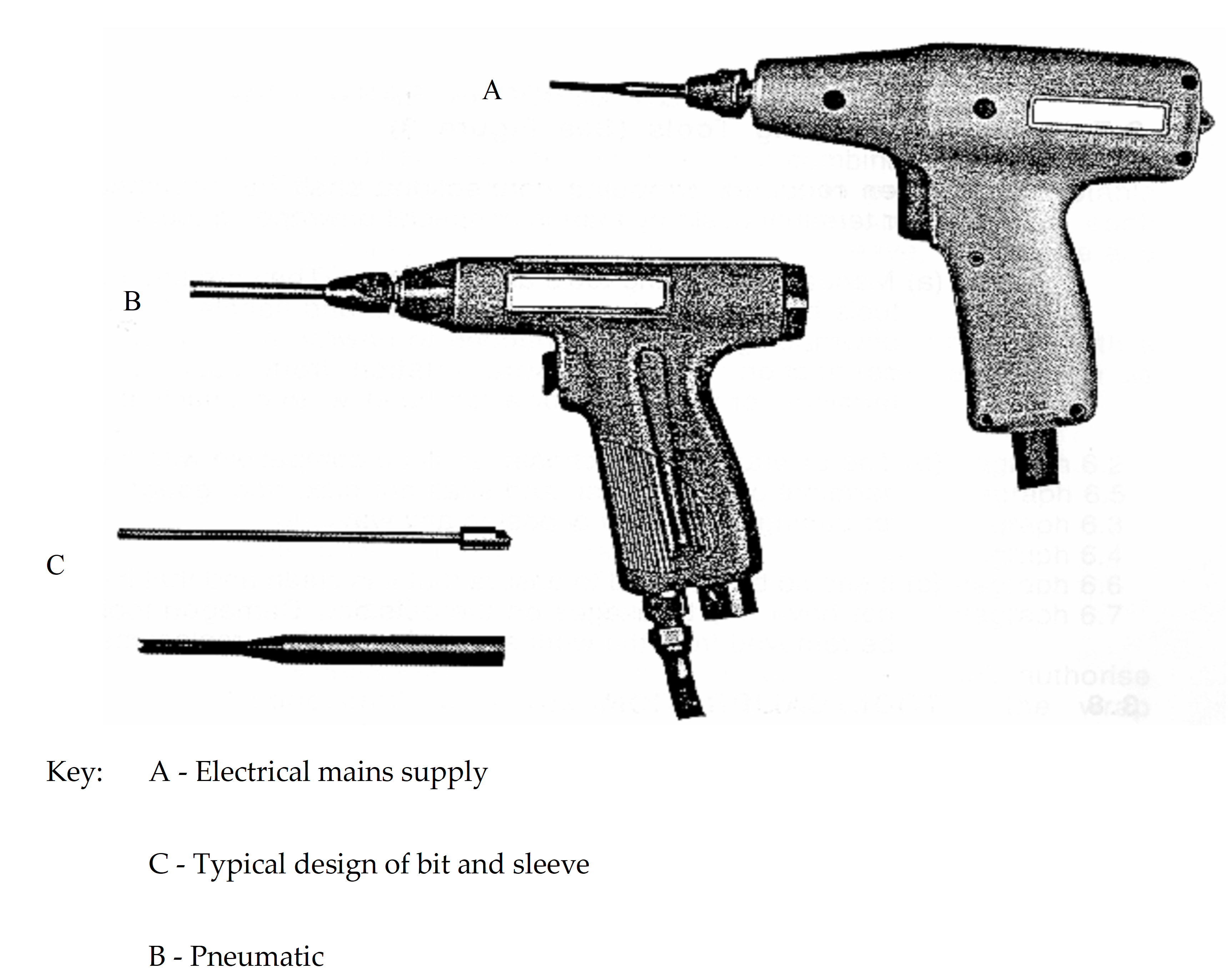 Figure: Examples of approved wirewrapping tools
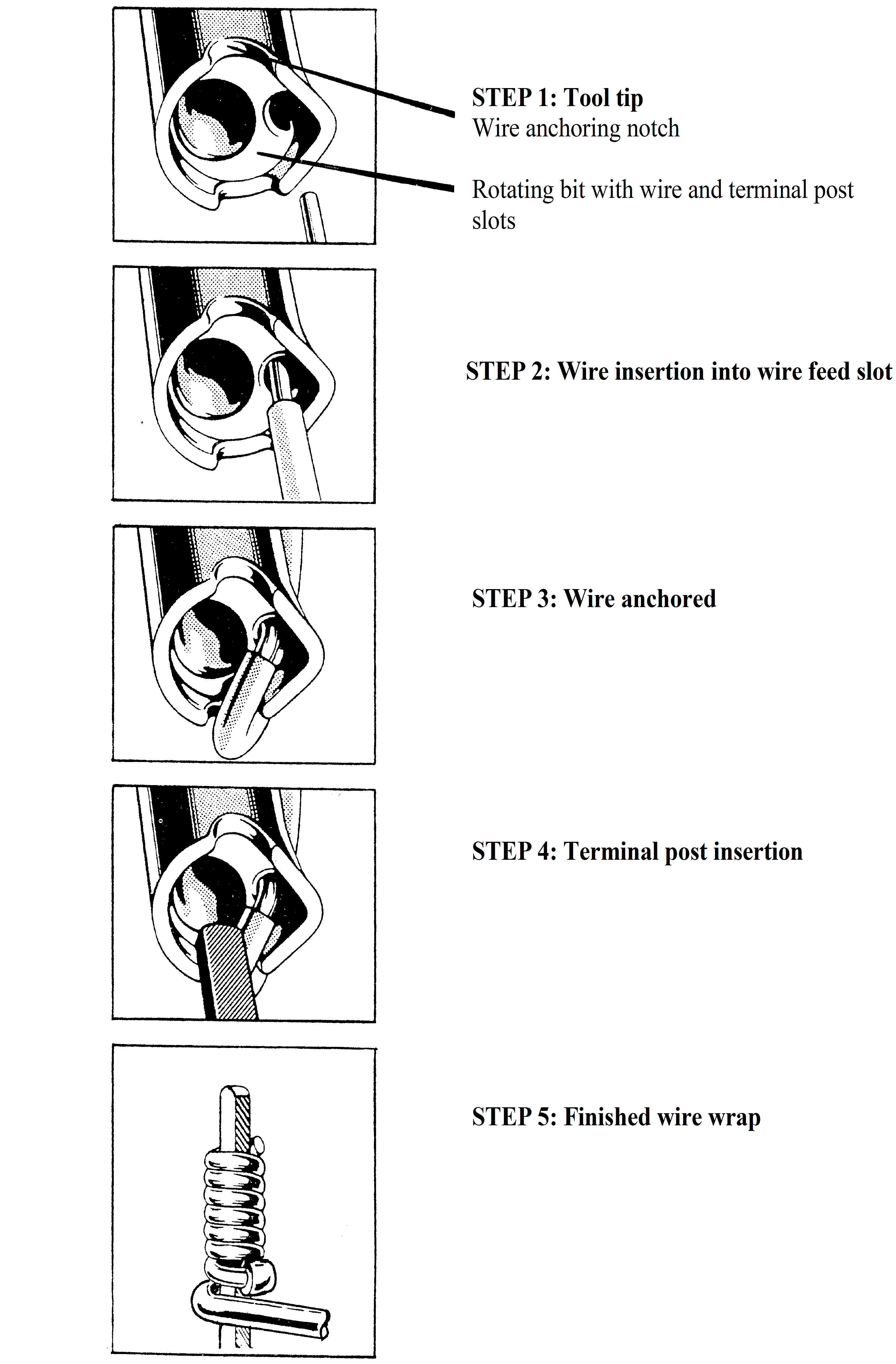 Figure: Wirewrap connection process
Rework procedure
A wirewrapped joint is not intended to be a “removable” joint, but it can be easily reprocessed. Reprocessing, or unwrapping followed by rewrapping is termed “rework”.
To disconnect a wrapped connection, the wrapped wire has to be carefully uncoiled using an approved hand tool (see clause 5.1.3.4 and Figure A-3, to preserve the corners of the terminal post.
Cut off the part of the wire which was previously wrapped on the terminal post, and if possible, prepare the wire end for rewrapping.
After inspection to confirm that the external condition of the post is satisfactory, the new length of stripped conductor, or a completely new interconnection wire length can then be wrapped onto the previously wrapped terminal post, provided that the post and connection are capable of conforming with the requirements of this specification.
The wire and terminal post materials and conditions are selected to enable joints to be reworked, with new wire each time:
up to 3 times, using copper alloy wire, or
up to 5 times, using soft copper wire.
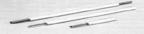 Figure: Hand unwrapping tools
Test procedures
Unwrapping test
It is recommended that the test be carried out under a low power binocular microscope, to permit continuous monitoring of the wire as it is unwrapped, and detection of any problems as they occur.
Perform the test as follows, using the appropriate unwrapping tool (see Figure A-3):
Place the tool on the end of the terminal post, ensuring that the end of the wire to be unwrapped enters the helical groove correctly. Slowly rotate the tool until all the wire has been transferred onto the tool. To ensure that no damage occurs in the lower turn, slight tension may be applied to the wire whilst the tool is being rotated.
When all the wire is unwrapped, carefully remove the tool with the loose helical coil of wire from the terminal post.
Holding the insulated portion of the wire firmly, with the tool perpendicular to the wire, unroll the wire by rotating the tool, whilst exerting slight tension along the wire.
Gas-tightness test
Carry out the gastight test as follows:
Suspend the test samples inside a glass vessel with a stopper containing 5 ml of aqua regia (1:1 concentrated hydrochloric acid and nitric acid), without contact with the acid. Expose the wirewrap samples to the aqua regia fumes for a duration of 10 minutes.
Immediately transfer and suspend the chemically attacked test samples to a second glass vessel containing 5 ml of concentrated ammonium sulphide solution, without contact with the liquid. Expose for several minutes to this atmosphere, necessary to obtain complete blackening of the surfaces of the samples.
Allow to dry, and carefully unwrap the wire from the blackened connection. The gastight areas appear bright in sharp contrast to the blackened exposed areas on the terminal post. Figure A-8illustrates a typical satisfactory test result, where the central region of the face of the terminal pin beneath the wirewrap has suffered attack and blackening.
Daily process control sheet for test samples
The data recorded for the purpose of documenting the results of pre- and post shift sample testing, see clause 5.6.8.3 are logged in a format looking like the example of Figure A-4.
|
Daily process control sheet for test samples
| |||||
|
Project:
|
Model:
|
Date:
| |||
|
Wire-wrap tool:
|
Terminal post:
|
Wire:
| |||
|
Quantity of manufactured connections
|
Visual result
|
Stripping force result()
|
Unwrap testresult
|
Conclusion
|
Name and date
|
Figure: Example of a daily process control sheet for test samples
Illustrative figures
The following Figures are included to provide complementary information to the text of clause 5.
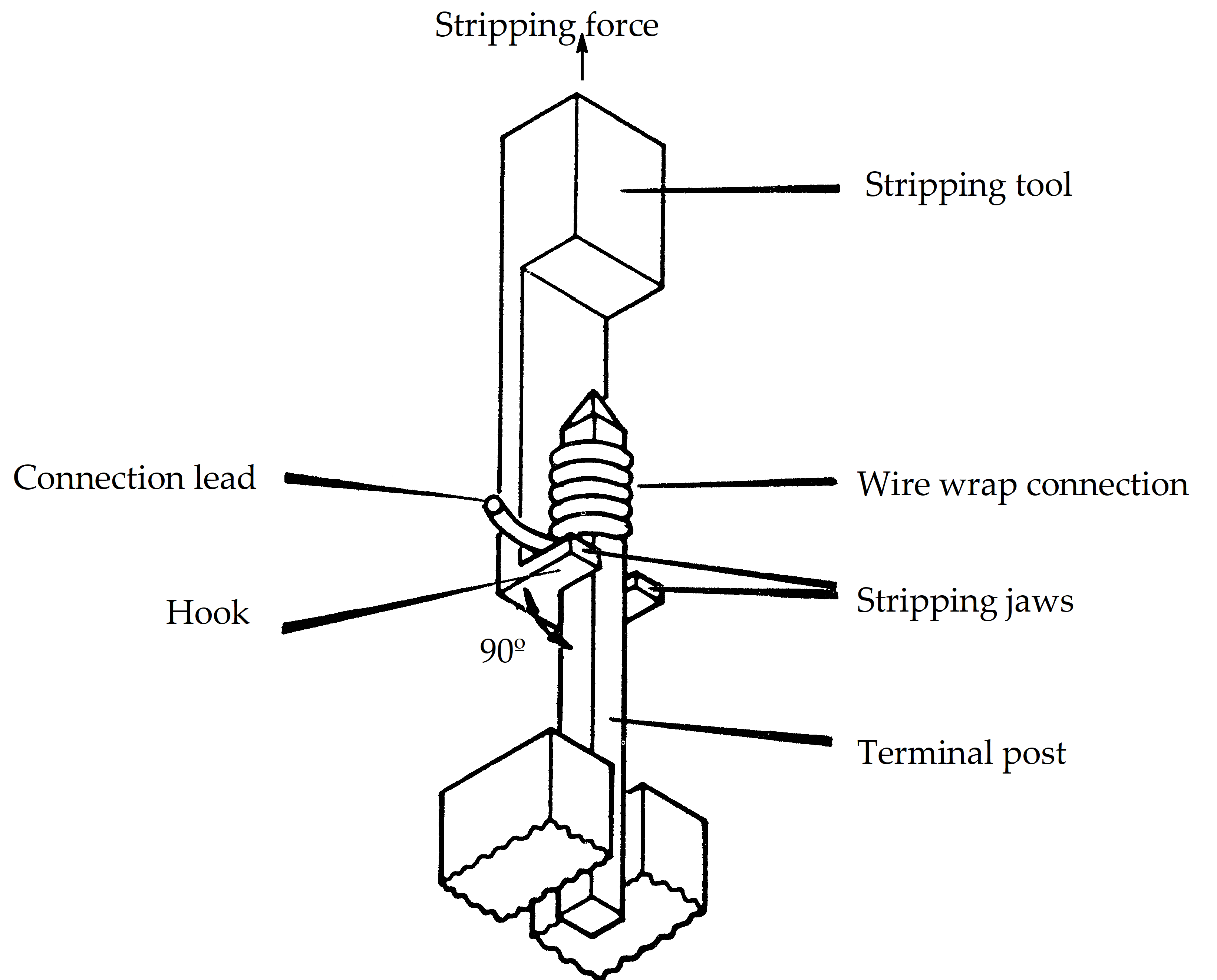 Figure: Stripping force test fixture
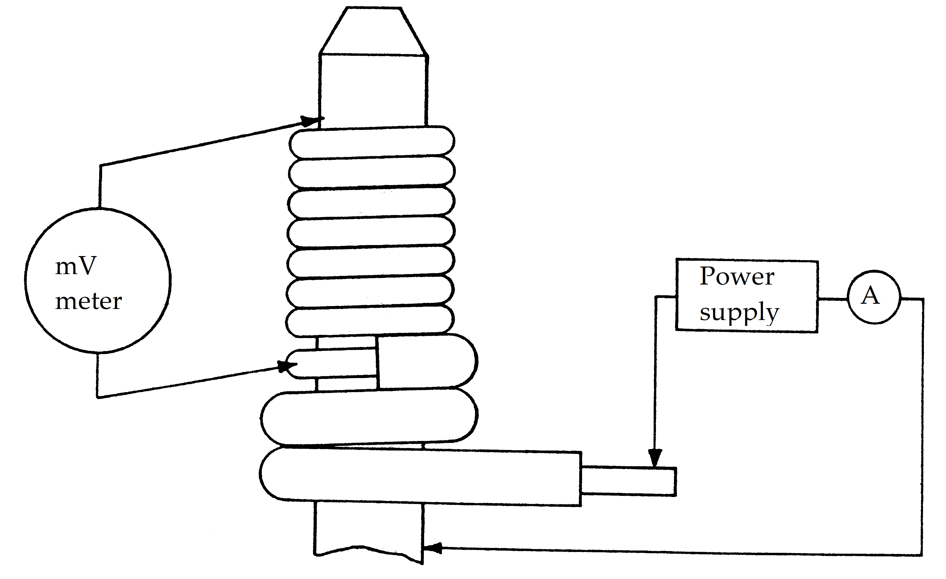 Figure: Connection resistance test
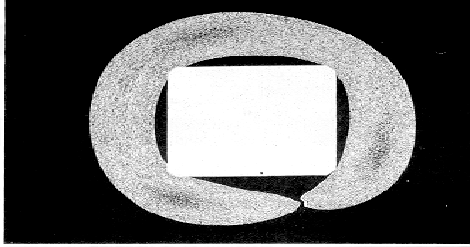 Figure: Typical crosssection of wirewrap (×64)
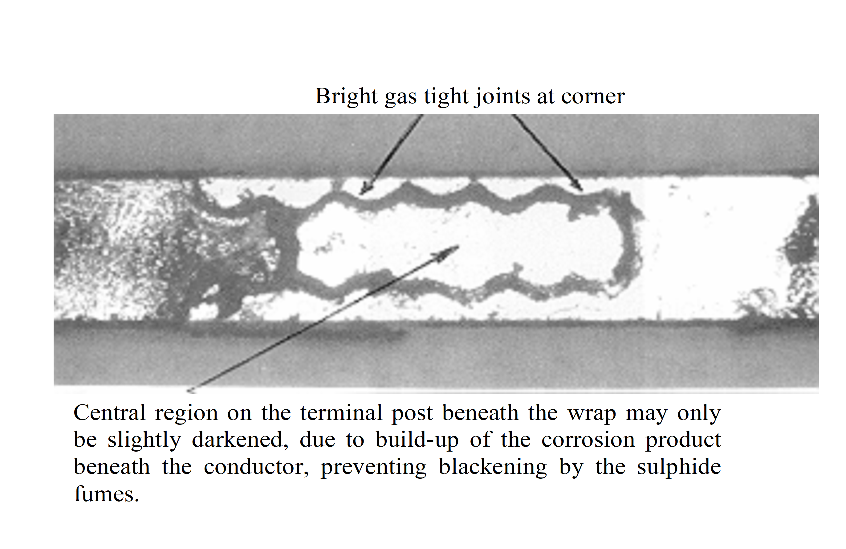 Figure: Gastightness test result
Bibliography
|
ECSS-S-ST-00
|
ECSS system – Description, implementation and general requirements
|
|
ECSSQST7008
|
Space product assurance Manual soldering of highreliability electrical connections
|
|
ECSSQST-7026
|
Space product assurance Crimping of high-reliability electrical connections
|
|
MILSTD1130
|
Connections, electrical, solderless wrapped
|
|
NASA NHB 5300.4(3H)
|
Requirements for crimping and wire wrap
|